EP3971585B1 - Optical air data system fusion with remote atmospheric sensing - Google Patents
Optical air data system fusion with remote atmospheric sensing Download PDFInfo
- Publication number
- EP3971585B1 EP3971585B1 EP21197544.6A EP21197544A EP3971585B1 EP 3971585 B1 EP3971585 B1 EP 3971585B1 EP 21197544 A EP21197544 A EP 21197544A EP 3971585 B1 EP3971585 B1 EP 3971585B1
- Authority
- EP
- European Patent Office
- Prior art keywords
- optical
- data
- air data
- air
- signal
- Prior art date
- Legal status (The legal status is an assumption and is not a legal conclusion. Google has not performed a legal analysis and makes no representation as to the accuracy of the status listed.)
- Active
Links
- 230000003287 optical effect Effects 0.000 title claims description 136
- 230000004927 fusion Effects 0.000 title description 22
- 239000000443 aerosol Substances 0.000 claims description 60
- 238000000034 method Methods 0.000 claims description 27
- 238000004458 analytical method Methods 0.000 claims description 21
- 238000007500 overflow downdraw method Methods 0.000 claims description 12
- 238000004422 calculation algorithm Methods 0.000 claims description 10
- 230000036541 health Effects 0.000 claims description 5
- 238000004891 communication Methods 0.000 claims description 4
- 238000007405 data analysis Methods 0.000 claims description 4
- 239000002245 particle Substances 0.000 claims description 4
- 238000001228 spectrum Methods 0.000 description 17
- 238000010586 diagram Methods 0.000 description 11
- 238000012545 processing Methods 0.000 description 7
- 238000013459 approach Methods 0.000 description 5
- 230000006870 function Effects 0.000 description 5
- 230000008901 benefit Effects 0.000 description 2
- 238000004364 calculation method Methods 0.000 description 2
- 230000001419 dependent effect Effects 0.000 description 2
- 238000001514 detection method Methods 0.000 description 2
- 238000005259 measurement Methods 0.000 description 2
- 230000007246 mechanism Effects 0.000 description 2
- 230000008569 process Effects 0.000 description 2
- 230000003595 spectral effect Effects 0.000 description 2
- 238000003491 array Methods 0.000 description 1
- 238000009530 blood pressure measurement Methods 0.000 description 1
- 238000009529 body temperature measurement Methods 0.000 description 1
- 238000004590 computer program Methods 0.000 description 1
- 239000000470 constituent Substances 0.000 description 1
- 230000003247 decreasing effect Effects 0.000 description 1
- 230000005855 radiation Effects 0.000 description 1
- 238000000827 velocimetry Methods 0.000 description 1
Images


Classifications
-
- G—PHYSICS
- G01—MEASURING; TESTING
- G01N—INVESTIGATING OR ANALYSING MATERIALS BY DETERMINING THEIR CHEMICAL OR PHYSICAL PROPERTIES
- G01N21/00—Investigating or analysing materials by the use of optical means, i.e. using sub-millimetre waves, infrared, visible or ultraviolet light
- G01N21/17—Systems in which incident light is modified in accordance with the properties of the material investigated
- G01N21/47—Scattering, i.e. diffuse reflection
- G01N21/49—Scattering, i.e. diffuse reflection within a body or fluid
- G01N21/53—Scattering, i.e. diffuse reflection within a body or fluid within a flowing fluid, e.g. smoke
- G01N21/538—Scattering, i.e. diffuse reflection within a body or fluid within a flowing fluid, e.g. smoke for determining atmospheric attenuation and visibility
-
- G—PHYSICS
- G01—MEASURING; TESTING
- G01N—INVESTIGATING OR ANALYSING MATERIALS BY DETERMINING THEIR CHEMICAL OR PHYSICAL PROPERTIES
- G01N15/00—Investigating characteristics of particles; Investigating permeability, pore-volume, or surface-area of porous materials
- G01N15/06—Investigating concentration of particle suspensions
-
- G—PHYSICS
- G01—MEASURING; TESTING
- G01C—MEASURING DISTANCES, LEVELS OR BEARINGS; SURVEYING; NAVIGATION; GYROSCOPIC INSTRUMENTS; PHOTOGRAMMETRY OR VIDEOGRAMMETRY
- G01C23/00—Combined instruments indicating more than one navigational value, e.g. for aircraft; Combined measuring devices for measuring two or more variables of movement, e.g. distance, speed or acceleration
-
- G—PHYSICS
- G01—MEASURING; TESTING
- G01P—MEASURING LINEAR OR ANGULAR SPEED, ACCELERATION, DECELERATION, OR SHOCK; INDICATING PRESENCE, ABSENCE, OR DIRECTION, OF MOVEMENT
- G01P13/00—Indicating or recording presence, absence, or direction, of movement
- G01P13/02—Indicating direction only, e.g. by weather vane
- G01P13/025—Indicating direction only, e.g. by weather vane indicating air data, i.e. flight variables of an aircraft, e.g. angle of attack, side slip, shear, yaw
-
- G—PHYSICS
- G01—MEASURING; TESTING
- G01S—RADIO DIRECTION-FINDING; RADIO NAVIGATION; DETERMINING DISTANCE OR VELOCITY BY USE OF RADIO WAVES; LOCATING OR PRESENCE-DETECTING BY USE OF THE REFLECTION OR RERADIATION OF RADIO WAVES; ANALOGOUS ARRANGEMENTS USING OTHER WAVES
- G01S17/00—Systems using the reflection or reradiation of electromagnetic waves other than radio waves, e.g. lidar systems
- G01S17/88—Lidar systems specially adapted for specific applications
- G01S17/95—Lidar systems specially adapted for specific applications for meteorological use
-
- G01N15/075—
-
- G—PHYSICS
- G01—MEASURING; TESTING
- G01N—INVESTIGATING OR ANALYSING MATERIALS BY DETERMINING THEIR CHEMICAL OR PHYSICAL PROPERTIES
- G01N15/00—Investigating characteristics of particles; Investigating permeability, pore-volume, or surface-area of porous materials
- G01N2015/0023—Investigating dispersion of liquids
- G01N2015/0026—Investigating dispersion of liquids in gas, e.g. fog
-
- G—PHYSICS
- G01—MEASURING; TESTING
- G01N—INVESTIGATING OR ANALYSING MATERIALS BY DETERMINING THEIR CHEMICAL OR PHYSICAL PROPERTIES
- G01N15/00—Investigating characteristics of particles; Investigating permeability, pore-volume, or surface-area of porous materials
- G01N2015/0042—Investigating dispersion of solids
- G01N2015/0046—Investigating dispersion of solids in gas, e.g. smoke
-
- G—PHYSICS
- G01—MEASURING; TESTING
- G01N—INVESTIGATING OR ANALYSING MATERIALS BY DETERMINING THEIR CHEMICAL OR PHYSICAL PROPERTIES
- G01N21/00—Investigating or analysing materials by the use of optical means, i.e. using sub-millimetre waves, infrared, visible or ultraviolet light
- G01N21/17—Systems in which incident light is modified in accordance with the properties of the material investigated
- G01N2021/1793—Remote sensing
- G01N2021/1795—Atmospheric mapping of gases
-
- G—PHYSICS
- G01—MEASURING; TESTING
- G01N—INVESTIGATING OR ANALYSING MATERIALS BY DETERMINING THEIR CHEMICAL OR PHYSICAL PROPERTIES
- G01N21/00—Investigating or analysing materials by the use of optical means, i.e. using sub-millimetre waves, infrared, visible or ultraviolet light
- G01N21/17—Systems in which incident light is modified in accordance with the properties of the material investigated
- G01N21/47—Scattering, i.e. diffuse reflection
- G01N2021/4704—Angular selective
- G01N2021/4709—Backscatter
-
- G—PHYSICS
- G01—MEASURING; TESTING
- G01N—INVESTIGATING OR ANALYSING MATERIALS BY DETERMINING THEIR CHEMICAL OR PHYSICAL PROPERTIES
- G01N2201/00—Features of devices classified in G01N21/00
- G01N2201/06—Illumination; Optics
- G01N2201/066—Modifiable path; multiple paths in one sample
- G01N2201/0668—Multiple paths; optimisable path length
-
- Y—GENERAL TAGGING OF NEW TECHNOLOGICAL DEVELOPMENTS; GENERAL TAGGING OF CROSS-SECTIONAL TECHNOLOGIES SPANNING OVER SEVERAL SECTIONS OF THE IPC; TECHNICAL SUBJECTS COVERED BY FORMER USPC CROSS-REFERENCE ART COLLECTIONS [XRACs] AND DIGESTS
- Y02—TECHNOLOGIES OR APPLICATIONS FOR MITIGATION OR ADAPTATION AGAINST CLIMATE CHANGE
- Y02A—TECHNOLOGIES FOR ADAPTATION TO CLIMATE CHANGE
- Y02A90/00—Technologies having an indirect contribution to adaptation to climate change
- Y02A90/10—Information and communication technologies [ICT] supporting adaptation to climate change, e.g. for weather forecasting or climate simulation
Definitions
- Air data parameters such as air speed, angle of attack (AOA), angle of sideslip (AOS), temperature, and pressure can be derived from the spectral content of the collected backscatter signal, which is dependent on aerosol and molecular parameters (e.g., aerosol and molecular concentration).
- AOA angle of attack
- AOS angle of sideslip
- temperature e.g., temperature
- pressure e.g., pressure
- Accurately extracting air data parameters from the collected backscatter signal can be challenging due to the numerous dependencies and degrees of freedom of a model fit for analyzing the air data.
- US2019302141A1 discloses an optical air data system for an air vehicle includes a LIDAR module and a data processing module.
- the LIDAR module is configured to emit at least three laser beams, not all located in a common plane, and perform LIDAR measurements of a backscattered component of each of the laser beams.
- US2004027570A1 discloses systems and methods for sensing air outside a moving aircraft.
- the system includes a laser for generating laser energy and one or more transceivers for projecting the laser energy as laser radiation to the air. Each transceiver receives laser energy as it is backscattered from the air.
- Optical air data fusion systems and methods which utilize remote atmospheric sensing, are described herein.
- the systems and methods are implemented to provide fusion of optical data from an optical air data system and an independent optical instrument.
- One or more data fusion algorithms can be used to improve the optical air data system computations.
- the present approach leverages other optical instruments that remotely measure the whole, or a subset, of atmospheric constituents that are measured by an optical air data system, to improve performance of the air data system.
- fusion of data from two airborne remote atmospheric interrogation instruments are used that can measure atmospheric conditions by different mechanisms.
- an air data fusion system includes an optical air data system that relies on both aerosol and molecular scattering to measure air data parameters, and another independent optical remote sensing instrument that measures aerosols and/or air molecules.
- an independent optical remote sensing instrument to measure the content of aerosols and/or molecules in the relevant interrogation volume, one or more parameters of the optical air data system can be known, thus improving the fit model to the data.
- an independent airborne remote sensing instrument mounted on an aircraft can measure the aerosol content of the atmosphere in an interrogation region by the aircraft. By knowing the aerosol content of the atmosphere, this information can be used to help an algorithm of an optical air data system, also mounted on the aircraft, to differentiate the portion of the total scattering from aerosols vs. molecular scattering.
- the aerosol vs. molecular scattering ratio can be calculated, and a data analysis algorithm can be tailored to optimize the remaining unknown parameters such as Doppler spectral shift.
- detector settings e.g., photodetector gains
- different detector settings can be controlled to allow for operation of the air data system in higher or lower aerosol concentration regions.
- the confidence level of an air data algorithm can be estimated, and the optical air data system health can be verified and output to an external user.
- the present system provides various technical benefits, including decreasing degrees of freedom of a model fit for analyzing air data, thereby improving the model fit accuracy and air data output accuracy.
- the present approach can also provide system redundancy information that allows checks to be carried out.
- the present system can also provide additional control to hardware and software settings to optimize operation (collection, processing, etc.) efficiency.
- the present approach can also provide input on system confidence level or reliability.
- FIG. 1A illustrates an optical air data fusion system 100, according to one embodiment.
- the system 100 includes an optical air data system 110 operative to measure aerosol and molecular scattering of light from an interrogation air region 130 in the atmosphere.
- the system 100 also includes an independent optical instrument 120 that provides remote sensing separate from air data system 110.
- optical instrument 120 is operative to measure aerosol and/or molecular scattering of light from interrogation air region 130.
- At least one processor 140 is operative to receive data from air data system 110, and also to receive data from optical instrument 120.
- the processor 140 is operative to perform one or more signal analysis and data fusion methods 142, and to provide an enhanced data output, as described in further detail hereafter.
- the air data system 110 comprises at least one light source, such as a laser transmitter 112, which is configured to transmit a light beam 114 into interrogation air region 130.
- a set of receive optics 115 in air data system 110 is configured to provide at least one receive channel.
- the receive optics 115 are configured to collect a scattered portion 116 of transmitted light beam 114 from one or more aerosols 132 and air molecules 134 in interrogation air region 130.
- laser transmitter 112 and receive optics 115 can be implemented in an optical transceiver.
- An optical detector 118 in air data system 110 is in communication with the receive channel and is configured to receive the collected scattered portion 116.
- the optical detector 118 is operative to measure a signal intensity as a function of frequency from scattered portion 116, and convert this data to an electrical signal that is sent to processor 140 for analysis.
- air data system 110 is configured for use on a vehicle such as an aircraft.
- air data system 110 comprises an optical air data sensor, including a laser transmitter and receive optics implemented in an optical transceiver, which has at least one line-of-sight that is fixed relative to the body axes of the vehicle.
- the optical air data sensor also includes the optical detector.
- the optical instrument 120 comprises at least one light source, such as a laser transmitter 122, which is configured to transmit a light beam 124 into interrogation air region 130.
- a set of receive optics 125 is configured to provide at least one receive channel.
- the receive optics 125 are configured to collect a scattered portion 126 of transmitted light beam 124 from the one or more aerosols 132 and/or air molecules 134 in interrogation air region 130.
- laser transmitter 122 and receive optics 125 can be implemented as part of an optical transceiver.
- An optical detector 128 is in communication with the receive channel and is configured to receive the collected scattered portion 126. The optical detector 128 is operative to convert the collected scatter data to an electrical signal that is sent to processor 140 for analysis.
- optical instrument 120 can be implemented in the form of a particle sensor assembly, which can be configured for use on a vehicle such as an airborne vehicle.
- the particle sensor assembly is operative to measure an aerosol scattering coefficient.
- optical detector 128 is operative to measure a signal intensity as a function of time from scattered portion 126.
- optical instrument 120 can be implemented in the form of optical sensor operative to measure a molecular scattering coefficient.
- optical instrument 120 can be implemented as a second air data system, including the features described above for air data system 110.
- optical instrument 120 can be implemented using an optical air data sensor, with the laser transmitter and receive optics implemented in an optical transceiver. This optical air data sensor also includes the optical detector, as described above.
- air data system 110 and optical instrument 120 are located on the same vehicle. In other embodiments, air data system 110 and optical instrument 120 are located on different vehicles, but are operative to interrogate the same atmospheric region.
- air data system 110 is located on a vehicle, and optical instrument 120 is located on the ground to provide ground-based optical remote sensing.
- air data system 110 (on vehicle) and optical instrument 120 (ground-based) are operative to interrogate the same atmospheric region.
- Optical instrument 120 can be optionally configured to send a control signal 150 to air data system 110, as shown in Figure 1A .
- the control signal 150 is operative to control hardware and software settings in air data system 110 to optimize operational efficiency.
- Figure 1B depicts graphical representations of exemplary receive optical spectra generated by air data fusion system 100.
- Figure 1B shows graphical representations of a receive optical spectrum 160 generated by optical air data system 110, and a receive optical spectrum 170 generated by independent optical instrument 120.
- the receive optical spectrum 160 includes a backscatter line shape 162 produced by Rayleigh scattering from air molecules 134 in the atmosphere of interrogation air region 130, and by Mie scattering from aerosols 132 in the atmosphere.
- the Rayleigh scattering and Mie scattering both contribute to backscatter line shape .
- the backscatter line shape 162 includes the Mie scattered contribution in the form of a narrow aerosol peak 164, which protrudes from the Rayleigh scattered contribution in the form of a broadening base 166.
- the receive optical spectrum 170 includes a backscatter line shape 172 produced by Mie scattering from the aerosols in the atmosphere.
- the backscatter line shape 172 includes the Mie scattered contribution in the form of an aerosol peak 174.
- the receive optical spectrum 170 generated by optical instrument 120 is used by processor 140 to help compute the receive optical spectrum 160 in air data system 110.
- aerosol peak 164 from optical instrument 120 can help to provide an enhanced signal analysis and data fusion, by taking what would otherwise be unconstrained fitting parameters in the air data system collected data, such as aerosol and molecular backscatter signal intensities, and have these parameters be constrained from the independent measurement of the aerosol backscatter signal strength from optical instrument 120. This allows the fitting of the data to mainly focus on the Doppler shifts in the detected spectra.
- air data parameters such as air speed, angle of attack (AOA), angle of sideslip (AOS), temperature, pressure, and the like, can then be derived from optical spectrum 160 using standard processing techniques.
- air speed which is related to the velocity of a moving vehicle, is derived from the Doppler shift between the center frequency of the backscattered signal and the laser frequency (discussed further below).
- Both air temperature and air pressure are convolved in the molecular linewidth of the backscattered spectrum (i.e., backscatter line shape 162).
- the width (w) of backscatter line shape 162 is dictated by the air temperature.
- the intensity i.e., area under the curve of backscatter line shape 162
- density which is directly related to the air pressure.
- a model is used to fit and subsequently deduce the air data parameters from backscatter line shape 162.
- the computed air data parameters are output from processor 140 to other systems, such as a vehicle computer for use in further vehicle data processing.
- processor 140 can send an estimated air speed to an avionics unit onboard the aircraft for further data processing.
- Figure 2A is a schematic view of an optical air data sensor 210, such as an incoherent hyperspectral (direct detection) sensor, which can be implemented as part of an optical air data system such as air data system 110 ( Fig. 1A ).
- the air data sensor 210 system 210 is designed to perform Doppler velocimetry from aerosol and molecular backscatter in an interrogation volume 230.
- the optical air data sensor 210 comprises a laser transmitter 212, which is configured to transmit a light beam with an optical frequency f 0 into interrogation volume 230.
- a receiver 215 is configured to receive backscatter light from interrogation volume 230, with the received backscatter light having frequency shift f (i.e., f 0 + ⁇ f ).
- Figure 2A shows a direction 240 of wind into interrogation volume 230, with the wind have a velocity ⁇ wind .
- Figure 2B is a plot showing an exemplary backscatter spectrum 250 produced by optical air data sensor 210, with the plot indicating the received molecular, aerosol, and total backscatter spectra shifted with respect to the transmit laser light.
- backscatter spectrum 250 is shifted with respect to a transmit spectra 244, and is distinguished by the contributions indicated by curve 254 and curve 256, which are the molecular and aerosol components, respectively.
- the combined signal that is measured by the system is shown by a curve 258.
- an incoherent hyperspectral system can measure air data parameters by fitting S [ f ] with free fitting parameters n A , n M , and ⁇ f .
- Some air data products are calculated from the molecular backscatter contribution M alone, including, but not limited to, air temperature and density.
- the aerosol backscatter contribution A may in some atmospheric conditions be larger or comparable to M. In such conditions where A is large, air data parameters originating from the molecular scattering signal alone may become more challenging to measure reliably because of the dominant signal A and its associated noise.
- air data parameters such as temperature and pressure are more sensitive to various types of aerosols, so that measuring temperature and pressure can be challenging in areas with a higher aerosol concentration.
- the higher aerosol concentration can reduce reliability of such temperature and pressure measurements.
- the utility of the fusion technique described herein is the fixing of n A from a secondary data source, such as an independent optical instrument, such that the number of free fitting parameters is reduced and n M , ⁇ f may be fitted with higher fidelity than if n A was a free fitting parameter.
- a secondary data source such as an independent optical instrument
- n M , ⁇ f may be fitted with higher fidelity than if n A was a free fitting parameter.
- the same procedure can be used to improve the fit fidelity to the remaining unknown fitting parameters.
- FIG 3 is a block diagram of one exemplary system operation 300, for an optical air data fusion system, such as air data fusion system 100 ( Figure 1A ).
- Figure 3 illustrates how an independent optical instrument such as optical instrument 120, can enhance the signal analysis performance of an optical air data system such as air data system 110, according to one implementation.
- air data system 110 obtains an aerosol and molecular backscatter signal from the interrogation air region, and a corresponding data signal 312 is sent to a processor, such as processor 140.
- the optical instrument 120 obtains an aerosol and/or molecular backscatter signal from the interrogation air region, and a corresponding data signal 314 is sent to processor 140.
- the processor 140 performs an enhanced signal analysis and data fusion method 320 based on the received data, which is described further hereafter.
- the processor 140 then outputs enhanced air data 330, such as enhanced air data parameters, to one or more other systems for use in further data processing.
- FIG 4 is a flow diagram of the enhanced signal analysis and data fusion method 320, which can be performed by the processor.
- the method 320 comprises determining an aerosol and/or molecular concentration in the interrogation air region from the received data signals (block 410).
- the method 320 can optionally calculate an aerosol verses molecular scattering ratio if needed (block 420).
- a data analysis algorithm is modified to optimize any remaining unknown parameters (block 430).
- the method 320 then outputs enhanced air data parameters (block 440).
- FIG 5 is a block diagram of another system operation 500, for an optical air data fusion system, such as air data fusion system 100 ( Figure 1A ).
- Figure 5 illustrates how an independent optical instrument such as optical instrument 120, can assist in the hardware settings and/or enhance the signal analysis performance of an optical air data system to provide an enhanced air data system 110.
- Air data system 110 obtains an aerosol and molecular backscatter signal from the interrogation air region
- optical instrument 120 obtains an aerosol and/or molecular backscatter signal from the interrogation air region.
- optical instrument 120 generates a hardware control signal 510 based on the aerosol and/or molecular backscatter signal.
- the hardware control signal 510 is sent to air data system 110 to aid in generating an enhanced aerosol and molecular backscatter signal, and a corresponding enhanced data signal 512 is sent to processor 140 from air data system 110.
- a data signal 514 corresponding to the obtained aerosol and/or molecular backscatter signal can also be sent from optical instrument 120 to processor 140.
- the processor 140 then performs an enhanced signal analysis and data fusion method 520 based on the received data, which is described further hereafter.
- the processor 140 then outputs enhanced air data 530, such as enhanced air data parameters, to one or more other systems for use in further data processing.
- Figure 6 is a flow diagram of the enhanced signal analysis and data fusion method 520, which can be performed by the processor.
- the method 520 comprises determining an aerosol concentration, or presence thereof, in the interrogation region from the received data (block 610).
- the method 520 dynamically optimizes the detector settings in the optical air data system to enhance a signal level and avoid system saturation (block 620).
- the method 520 then outputs enhanced air data parameters.
- Figure 7 is a flow diagram of another method 700 for providing enhanced signal analysis and data fusion, which can be performed by the processor.
- the method 700 comprises determining an aerosol and/or molecular concentration, or presence thereof, in the interrogation region from the received data (block 710).
- the method 700 estimates a confidence level of an air data algorithm in the processor (block 720).
- the method 700 verifies the optical health of the optical air data system (block 730), and reports the optical health to an external user (block 740).
- a computer or processor used in the present systems and methods can be implemented using software, firmware, hardware, or any appropriate combination thereof, as known to one of skill in the art. These may be supplemented by, or incorporated in, specially-designed application-specific integrated circuits (ASICs) or field programmable gate arrays (FPGAs).
- ASICs application-specific integrated circuits
- FPGAs field programmable gate arrays
- the computer or processor can also include functions with software programs, firmware, or other computer readable instructions for carrying out various process tasks, calculations, and control functions used in the present systems and methods.
- the present methods can be implemented by computer executable instructions, such as program modules or components, which are executed by at least one processor.
- program modules include routines, programs, objects, data components, data structures, algorithms, and the like, which perform particular tasks or implement particular abstract data types.
- Instructions for carrying out the various process tasks, calculations, and generation of other data used in the operation of the methods described herein can be implemented in software, firmware, or other computer- or processor-readable instructions. These instructions are typically stored on any appropriate computer program product that includes a computer readable medium used for storage of computer readable instructions or data structures. Such a computer readable medium can be any available media that can be accessed by a general purpose or special purpose computer or processor, or any programmable logic device.
- Suitable processor-readable media may include storage or memory media such as magnetic or optical media.
- storage or memory media may include conventional hard disks, compact discs, DVDs, Blu-ray discs, or other optical storage media; volatile or nonvolatile media such as Random Access Memory (RAM); Read Only Memory (ROM), Electrically Erasable Programmable ROM (EEPROM), flash memory, and the like; or any other media that can be used to carry or store desired program code in the form of computer executable instructions or data structures.
- RAM Random Access Memory
- ROM Read Only Memory
- EEPROM Electrically Erasable Programmable ROM
- flash memory and the like
- any other media that can be used to carry or store desired program code in the form of computer executable instructions or data structures.
Description
- Optical air data systems collect the optical backscatter from aerosols and air molecules in the atmosphere. Air data parameters such as air speed, angle of attack (AOA), angle of sideslip (AOS), temperature, and pressure can be derived from the spectral content of the collected backscatter signal, which is dependent on aerosol and molecular parameters (e.g., aerosol and molecular concentration). Accurately extracting air data parameters from the collected backscatter signal can be challenging due to the numerous dependencies and degrees of freedom of a model fit for analyzing the air data.
US2019302141A1 discloses an optical air data system for an air vehicle includes a LIDAR module and a data processing module. The LIDAR module is configured to emit at least three laser beams, not all located in a common plane, and perform LIDAR measurements of a backscattered component of each of the laser beams.US2004027570A1 discloses systems and methods for sensing air outside a moving aircraft. The system includes a laser for generating laser energy and one or more transceivers for projecting the laser energy as laser radiation to the air. Each transceiver receives laser energy as it is backscattered from the air. - The present invention is defined by the independent claims to which reference should now be made. Advantageous embodiments are set out in the dependent claims.
- Features of the present invention will become apparent to those skilled in the art from the following description with reference to the drawings. Understanding that the drawings depict typical embodiments and are not therefore to be considered limiting in scope, the invention will be described with additional specificity and detail through the use of the accompanying drawings, in which:
-
Figure 1A is a block diagram of an optical air data fusion system, according to one embodiment; -
Figure 1B depicts graphical representations of exemplary receive optical spectra generated by the air data fusion system ofFigure 1A ; -
Figure 2A is a schematic view of an optical air data sensor, which can be implemented as part of the air data fusion system ofFigure 1A ; -
Figure 2B is a plot showing an exemplary backscatter spectrum produced by the optical air data sensor ofFigure 2A ; -
Figure 3 is a block diagram of one exemplary system operation for an optical air data fusion system; -
Figure 4 is a flow diagram of one enhanced signal analysis and data fusion method, which can be performed by a processor in the exemplary system operation ofFigure 3 ; -
Figure 5 is a block diagram of another exemplary system operation for an optical air data fusion system; -
Figure 6 is a flow diagram of another enhanced signal analysis and data fusion method, which can be performed by a processor in the exemplary system operation ofFigure 5 ; and -
Figure 7 is a flow diagram of a further method for providing enhanced signal analysis and data fusion, which can be performed by a processor in an optical air data fusion system. - In the following detailed description, embodiments are described in sufficient detail to enable those skilled in the art to practice the invention. It is to be understood that other embodiments may be utilized without departing from the scope of the invention. The following detailed description is, therefore, not to be taken in a limiting sense.
- Optical air data fusion systems and methods, which utilize remote atmospheric sensing, are described herein. The systems and methods are implemented to provide fusion of optical data from an optical air data system and an independent optical instrument. One or more data fusion algorithms can be used to improve the optical air data system computations.
- The present approach leverages other optical instruments that remotely measure the whole, or a subset, of atmospheric constituents that are measured by an optical air data system, to improve performance of the air data system. In one implementation, fusion of data from two airborne remote atmospheric interrogation instruments are used that can measure atmospheric conditions by different mechanisms.
- As described previously, it may be difficult to accurately extract air data parameters from a collected backscatter signal due to the numerous dependencies and degrees of freedom of the model fit for analyzing the air data. The present approach provides that a subset of such dependencies can be known or measured by another mechanism, which can reduce the degrees of freedom of the model fit. Reducing the degrees of freedom of the model fit can provide more robust air data parameters and higher reliability (fidelity to truth) in widely-varied optical backscatter conditions.
- In one embodiment, an air data fusion system includes an optical air data system that relies on both aerosol and molecular scattering to measure air data parameters, and another independent optical remote sensing instrument that measures aerosols and/or air molecules. By using an independent optical remote sensing instrument to measure the content of aerosols and/or molecules in the relevant interrogation volume, one or more parameters of the optical air data system can be known, thus improving the fit model to the data.
- In one example, an independent airborne remote sensing instrument mounted on an aircraft can measure the aerosol content of the atmosphere in an interrogation region by the aircraft. By knowing the aerosol content of the atmosphere, this information can be used to help an algorithm of an optical air data system, also mounted on the aircraft, to differentiate the portion of the total scattering from aerosols vs. molecular scattering.
- In one operational method, by knowing the aerosol and/or molecular concentration, the aerosol vs. molecular scattering ratio can be calculated, and a data analysis algorithm can be tailored to optimize the remaining unknown parameters such as Doppler spectral shift.
- In an operational method, by knowing the aerosol concentration or its presence, detector settings (e.g., photodetector gains) in the air data system are optimized dynamically to improve signal level and avoid system saturation. For example, different detector settings can be controlled to allow for operation of the air data system in higher or lower aerosol concentration regions.
- In a further operational method, by knowing the aerosol and/or molecular concentration or its presence, the confidence level of an air data algorithm can be estimated, and the optical air data system health can be verified and output to an external user.
- The present system provides various technical benefits, including decreasing degrees of freedom of a model fit for analyzing air data, thereby improving the model fit accuracy and air data output accuracy. The present approach can also provide system redundancy information that allows checks to be carried out. The present system can also provide additional control to hardware and software settings to optimize operation (collection, processing, etc.) efficiency. The present approach can also provide input on system confidence level or reliability.
- Other advantages of the present system include providing higher value to users through increased accuracy, reliability, and confidence level of the optical air data system. The present approach also make it easier to qualify for certification reliability requirements.
- Further details of various embodiments are described hereafter with reference to the drawings.
-
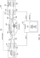
Figure 1A illustrates an optical air data fusion system 100, according to one embodiment. The system 100 includes an opticalair data system 110 operative to measure aerosol and molecular scattering of light from aninterrogation air region 130 in the atmosphere. The system 100 also includes an independentoptical instrument 120 that provides remote sensing separate fromair data system 110. As such,optical instrument 120 is operative to measure aerosol and/or molecular scattering of light frominterrogation air region 130. At least oneprocessor 140 is operative to receive data fromair data system 110, and also to receive data fromoptical instrument 120. Theprocessor 140 is operative to perform one or more signal analysis anddata fusion methods 142, and to provide an enhanced data output, as described in further detail hereafter. - The
air data system 110 comprises at least one light source, such as alaser transmitter 112, which is configured to transmit alight beam 114 intointerrogation air region 130. A set of receiveoptics 115 inair data system 110 is configured to provide at least one receive channel. The receiveoptics 115 are configured to collect ascattered portion 116 of transmittedlight beam 114 from one ormore aerosols 132 andair molecules 134 ininterrogation air region 130. In one embodiment,laser transmitter 112 and receiveoptics 115 can be implemented in an optical transceiver. Anoptical detector 118 inair data system 110 is in communication with the receive channel and is configured to receive the collectedscattered portion 116. Theoptical detector 118 is operative to measure a signal intensity as a function of frequency fromscattered portion 116, and convert this data to an electrical signal that is sent toprocessor 140 for analysis. - In one embodiment,
air data system 110 is configured for use on a vehicle such as an aircraft. In this embodiment,air data system 110 comprises an optical air data sensor, including a laser transmitter and receive optics implemented in an optical transceiver, which has at least one line-of-sight that is fixed relative to the body axes of the vehicle. The optical air data sensor also includes the optical detector. - The
optical instrument 120 comprises at least one light source, such as alaser transmitter 122, which is configured to transmit alight beam 124 intointerrogation air region 130. A set of receiveoptics 125 is configured to provide at least one receive channel. The receiveoptics 125 are configured to collect ascattered portion 126 of transmittedlight beam 124 from the one ormore aerosols 132 and/orair molecules 134 ininterrogation air region 130. In one embodiment,laser transmitter 122 and receiveoptics 125 can be implemented as part of an optical transceiver. Anoptical detector 128 is in communication with the receive channel and is configured to receive the collectedscattered portion 126. Theoptical detector 128 is operative to convert the collected scatter data to an electrical signal that is sent toprocessor 140 for analysis. - In one embodiment,
optical instrument 120 can be implemented in the form of a particle sensor assembly, which can be configured for use on a vehicle such as an airborne vehicle. The particle sensor assembly is operative to measure an aerosol scattering coefficient. In this case,optical detector 128 is operative to measure a signal intensity as a function of time fromscattered portion 126. There are various other optical sensors currently available that utilize optical detection schemes for particles or aerosols. In another embodiment,optical instrument 120 can be implemented in the form of optical sensor operative to measure a molecular scattering coefficient. - Alternatively,
optical instrument 120 can be implemented as a second air data system, including the features described above forair data system 110. For example,optical instrument 120 can be implemented using an optical air data sensor, with the laser transmitter and receive optics implemented in an optical transceiver. This optical air data sensor also includes the optical detector, as described above. - In some embodiments,
air data system 110 andoptical instrument 120 are located on the same vehicle. In other embodiments,air data system 110 andoptical instrument 120 are located on different vehicles, but are operative to interrogate the same atmospheric region. - In further embodiments,
air data system 110 is located on a vehicle, andoptical instrument 120 is located on the ground to provide ground-based optical remote sensing. In these embodiments, air data system 110 (on vehicle) and optical instrument 120 (ground-based) are operative to interrogate the same atmospheric region. -
Optical instrument 120 can be optionally configured to send acontrol signal 150 toair data system 110, as shown inFigure 1A . Thecontrol signal 150 is operative to control hardware and software settings inair data system 110 to optimize operational efficiency. -
Figure 1B depicts graphical representations of exemplary receive optical spectra generated by air data fusion system 100. In particular,Figure 1B shows graphical representations of a receiveoptical spectrum 160 generated by opticalair data system 110, and a receiveoptical spectrum 170 generated by independentoptical instrument 120. - The receive
optical spectrum 160 includes abackscatter line shape 162 produced by Rayleigh scattering fromair molecules 134 in the atmosphere ofinterrogation air region 130, and by Mie scattering fromaerosols 132 in the atmosphere. The Rayleigh scattering and Mie scattering both contribute to backscatter line shape . Thebackscatter line shape 162 includes the Mie scattered contribution in the form of anarrow aerosol peak 164, which protrudes from the Rayleigh scattered contribution in the form of abroadening base 166. - The receive
optical spectrum 170 includes abackscatter line shape 172 produced by Mie scattering from the aerosols in the atmosphere. Thebackscatter line shape 172 includes the Mie scattered contribution in the form of anaerosol peak 174. The receiveoptical spectrum 170 generated byoptical instrument 120 is used byprocessor 140 to help compute the receiveoptical spectrum 160 inair data system 110. - For example,
aerosol peak 164 fromoptical instrument 120 can help to provide an enhanced signal analysis and data fusion, by taking what would otherwise be unconstrained fitting parameters in the air data system collected data, such as aerosol and molecular backscatter signal intensities, and have these parameters be constrained from the independent measurement of the aerosol backscatter signal strength fromoptical instrument 120. This allows the fitting of the data to mainly focus on the Doppler shifts in the detected spectra. Various air data parameters, such as air speed, angle of attack (AOA), angle of sideslip (AOS), temperature, pressure, and the like, can then be derived fromoptical spectrum 160 using standard processing techniques. - For example, air speed, which is related to the velocity of a moving vehicle, is derived from the Doppler shift between the center frequency of the backscattered signal and the laser frequency (discussed further below). Both air temperature and air pressure are convolved in the molecular linewidth of the backscattered spectrum (i.e., backscatter line shape 162). The width (w) of
backscatter line shape 162 is dictated by the air temperature. The intensity (i.e., area under the curve of backscatter line shape 162) is dictated by the density, which is directly related to the air pressure. Typically, a model is used to fit and subsequently deduce the air data parameters frombackscatter line shape 162. - The computed air data parameters are output from
processor 140 to other systems, such as a vehicle computer for use in further vehicle data processing. For example, when the vehicle is an aircraft,processor 140 can send an estimated air speed to an avionics unit onboard the aircraft for further data processing. -
Figure 2A is a schematic view of an opticalair data sensor 210, such as an incoherent hyperspectral (direct detection) sensor, which can be implemented as part of an optical air data system such as air data system 110 (Fig. 1A ). Theair data sensor 210system 210 is designed to perform Doppler velocimetry from aerosol and molecular backscatter in aninterrogation volume 230. The opticalair data sensor 210 comprises alaser transmitter 212, which is configured to transmit a light beam with an optical frequency f 0 intointerrogation volume 230. Areceiver 215 is configured to receive backscatter light frominterrogation volume 230, with the received backscatter light having frequency shift f (i.e., f 0 + δf). In addition,Figure 2A shows adirection 240 of wind intointerrogation volume 230, with the wind have a velocity ν wind. -
Figure 2B is a plot showing anexemplary backscatter spectrum 250 produced by opticalair data sensor 210, with the plot indicating the received molecular, aerosol, and total backscatter spectra shifted with respect to the transmit laser light. In particular,backscatter spectrum 250 is shifted with respect to a transmitspectra 244, and is distinguished by the contributions indicated bycurve 254 andcurve 256, which are the molecular and aerosol components, respectively. The combined signal that is measured by the system is shown by acurve 258. - The spectrum of the backscatter light S[δf], where δf ≡ f - f 0 is the frequency shift of the received light f and the transmitter optical frequency f 0, centered at Doppler shift Δf, received by an optical air data system sensitive to aerosol (A) and molecular (M) scattering, may be given by the following expression:

- In general, an incoherent hyperspectral system can measure air data parameters by fitting S[f] with free fitting parameters nA, nM, and Δf. Some air data products are calculated from the molecular backscatter contribution M alone, including, but not limited to, air temperature and density. However, the aerosol backscatter contribution A may in some atmospheric conditions be larger or comparable to M. In such conditions where A is large, air data parameters originating from the molecular scattering signal alone may become more challenging to measure reliably because of the dominant signal A and its associated noise.
- For example, air data parameters such as temperature and pressure are more sensitive to various types of aerosols, so that measuring temperature and pressure can be challenging in areas with a higher aerosol concentration. In addition, the higher aerosol concentration can reduce reliability of such temperature and pressure measurements.
- The utility of the fusion technique described herein is the fixing of nA from a secondary data source, such as an independent optical instrument, such that the number of free fitting parameters is reduced and nM, Δf may be fitted with higher fidelity than if nA was a free fitting parameter. Alternatively, if nM or a linear combination of nA and nM is measured by the secondary data source, the same procedure can be used to improve the fit fidelity to the remaining unknown fitting parameters.
-
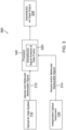
Figure 3 is a block diagram of oneexemplary system operation 300, for an optical air data fusion system, such as air data fusion system 100 (Figure 1A ).Figure 3 illustrates how an independent optical instrument such asoptical instrument 120, can enhance the signal analysis performance of an optical air data system such asair data system 110, according to one implementation. In this example,air data system 110 obtains an aerosol and molecular backscatter signal from the interrogation air region, and a corresponding data signal 312 is sent to a processor, such asprocessor 140. Theoptical instrument 120 obtains an aerosol and/or molecular backscatter signal from the interrogation air region, and a corresponding data signal 314 is sent toprocessor 140. Theprocessor 140 performs an enhanced signal analysis anddata fusion method 320 based on the received data, which is described further hereafter. Theprocessor 140 then outputsenhanced air data 330, such as enhanced air data parameters, to one or more other systems for use in further data processing. -
Figure 4 is a flow diagram of the enhanced signal analysis anddata fusion method 320, which can be performed by the processor. Themethod 320 comprises determining an aerosol and/or molecular concentration in the interrogation air region from the received data signals (block 410). Themethod 320 can optionally calculate an aerosol verses molecular scattering ratio if needed (block 420). A data analysis algorithm is modified to optimize any remaining unknown parameters (block 430). Themethod 320 then outputs enhanced air data parameters (block 440). -
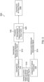
Figure 5 is a block diagram of anothersystem operation 500, for an optical air data fusion system, such as air data fusion system 100 (Figure 1A ).Figure 5 illustrates how an independent optical instrument such asoptical instrument 120, can assist in the hardware settings and/or enhance the signal analysis performance of an optical air data system to provide an enhancedair data system 110.Air data system 110 obtains an aerosol and molecular backscatter signal from the interrogation air region, andoptical instrument 120 obtains an aerosol and/or molecular backscatter signal from the interrogation air region. In addition,optical instrument 120 generates ahardware control signal 510 based on the aerosol and/or molecular backscatter signal. Thehardware control signal 510 is sent toair data system 110 to aid in generating an enhanced aerosol and molecular backscatter signal, and a corresponding enhanced data signal 512 is sent toprocessor 140 fromair data system 110. - A data signal 514 corresponding to the obtained aerosol and/or molecular backscatter signal can also be sent from
optical instrument 120 toprocessor 140. Theprocessor 140 then performs an enhanced signal analysis anddata fusion method 520 based on the received data, which is described further hereafter. Theprocessor 140 then outputsenhanced air data 530, such as enhanced air data parameters, to one or more other systems for use in further data processing. -
Figure 6 is a flow diagram of the enhanced signal analysis anddata fusion method 520, which can be performed by the processor. Themethod 520 comprises determining an aerosol concentration, or presence thereof, in the interrogation region from the received data (block 610). Themethod 520 dynamically optimizes the detector settings in the optical air data system to enhance a signal level and avoid system saturation (block 620). Themethod 520 then outputs enhanced air data parameters. -
Figure 7 is a flow diagram of anothermethod 700 for providing enhanced signal analysis and data fusion, which can be performed by the processor. Themethod 700 comprises determining an aerosol and/or molecular concentration, or presence thereof, in the interrogation region from the received data (block 710). Themethod 700 then estimates a confidence level of an air data algorithm in the processor (block 720). Themethod 700 verifies the optical health of the optical air data system (block 730), and reports the optical health to an external user (block 740). - A computer or processor used in the present systems and methods can be implemented using software, firmware, hardware, or any appropriate combination thereof, as known to one of skill in the art. These may be supplemented by, or incorporated in, specially-designed application-specific integrated circuits (ASICs) or field programmable gate arrays (FPGAs). The computer or processor can also include functions with software programs, firmware, or other computer readable instructions for carrying out various process tasks, calculations, and control functions used in the present systems and methods.
- The present methods can be implemented by computer executable instructions, such as program modules or components, which are executed by at least one processor. Generally, program modules include routines, programs, objects, data components, data structures, algorithms, and the like, which perform particular tasks or implement particular abstract data types.
- Instructions for carrying out the various process tasks, calculations, and generation of other data used in the operation of the methods described herein can be implemented in software, firmware, or other computer- or processor-readable instructions. These instructions are typically stored on any appropriate computer program product that includes a computer readable medium used for storage of computer readable instructions or data structures. Such a computer readable medium can be any available media that can be accessed by a general purpose or special purpose computer or processor, or any programmable logic device.
- Suitable processor-readable media may include storage or memory media such as magnetic or optical media. For example, storage or memory media may include conventional hard disks, compact discs, DVDs, Blu-ray discs, or other optical storage media; volatile or nonvolatile media such as Random Access Memory (RAM); Read Only Memory (ROM), Electrically Erasable Programmable ROM (EEPROM), flash memory, and the like; or any other media that can be used to carry or store desired program code in the form of computer executable instructions or data structures.
- The present invention may be embodied in other specific forms without departing from its essential characteristics as set out in the appended set of claims. The described embodiments are to be considered as illustrative and not restrictive. The scope of the invention is therefore indicated by the appended claims rather than by the foregoing description.
Claims (13)
- A system (100) comprising:an optical air data system (110) operative to measure aerosol and molecular scattering of light from an interrogation region (130) and to derive therefrom air data parameters;an optical instrument (120) separate from the optical air data system (110), the optical instrument (120) operative to measure aerosol and/or molecular scattering of light from the interrogation region (130); anda processor (140) operative to receive data from the optical air data system (110) and data from the optical instrument (120), wherein the processor (140) is configured to perform a signal analysis and data fusion method, comprising:determining an aerosol concentration, or presence thereof, in the interrogation region (130) from the received data from the optical air data system (110) and the optical instrument (120);based on the determined aerosol concentration or presence thereof,dynamically optimizing detector settings in the optical air data system (110) to enhance a signal level and avoid system saturation; andoutputting enhanced air data parameters.
- The system (100) of claim 1, wherein the processor (140) is configured to perform a signal analysis and data fusion method, comprising:determining an aerosol and/or molecular concentration in the interrogation region (130) from the received data from the optical air data system (110) and the optical instrument (120);modifying a data analysis algorithm used by the optical air data system to optimize unknown parameters of the data analysis algorithm; andoutputting enhanced air data parameters.
- The system (100) of claim 1 or 2, wherein the processor (140) is configured to perform a signal analysis and data fusion method, comprising:determining an aerosol and/or molecular concentration, or presence thereof, in the interrogation region (130) from the received data from the optical air data system (110) and the optical instrument (120);estimating a confidence level of an air data algorithm in the processor (140);verifying optical health of the optical air data system (110); andreporting the optical health to an external user.
- The system (100) of any of claims 1 to 3, wherein the optical air data system (110) comprises:a first light source configured to transmit a first light beam into the interrogation region (130);a first set of receive optics (115, 125) providing a first receive channel, the first set of receive optics (115, 125) configured to collect a first scattered portion (116, 126) of the transmitted first light beam from one or more aerosols (132) and air molecules (134) in the interrogation region (130); anda first optical detector (118, 128) in communication with the first receive channel and configured to receive the collected first scattered portion (116, 126), the first optical detector (118, 128) operative convert the first scattered portion (116, 126) to a first data signal (312, 314, 514) that is sent to the processor (140) for analysis.
- The system (100) of any of claims 1 to 4, wherein the optical air data system (110) comprises an incoherent hyperspectral system (100).
- The system (100) of claim 4, wherein the optical instrument (120) comprises:a second light source configured to transmit a second light beam into the interrogation region (130);a second set of receive optics (115, 125) providing a second receive channel, the second set of receive optics (115, 125) configured to collect a second scattered portion (116, 126) of the transmitted second light beam from one or more aerosols (132) and/or air molecules (134) in the interrogation region (130); anda second optical detector (118, 128) in communication with the second receive channel and configured to receive the collected second scattered portion (116, 126), the second optical detector (118, 128) operative convert the second scattered portion (116, 126) to a second data signal that is sent to the processor (140) for analysis.
- The system (100) of any of claims 1 to 5, wherein the optical instrument (120) comprises a particle sensor assembly operative to measure an aerosol scattering coefficient.
- The system (100) of any of claims 1 to 6, wherein the optical instrument (120) comprises an optical sensor operative to measure a molecular scattering coefficient.
- The system (100) of any of claims 1 to 8, wherein:the optical air data system (110) and the optical instrument (120) are mounted on one or more vehicles; orthe optical air data system (110) is mounted on a vehicle, and the optical instrument (120) is ground-based.
- The system (100) of claim 9, wherein the one or more vehicles include aircraft.
- The system (100) of any of claims 1 to 10, wherein the optical instrument (120) is configured to send a control signal (150, 510) to the air data system (110), the control signal (150, 510) operative to control hardware and software settings in the optical air data system (110) to optimize operational efficiency.
- The system (100) of claim 11, wherein the optical instrument (120) is configured to send the control signal (150, 510) directly to the air data system (110).
- A method comprising:obtaining a first backscatter signal, from one or more aerosols (132) and air molecules (134) in an interrogation region (130), using an optical air data system (110) that generates a first data signal (312, 512) of air data parameters corresponding to the first backscatter signal;sending the first data signal (312, 512) to a processor (140);obtaining a second backscatter signal, from one or more aerosols (132) and/or air molecules (134) in the interrogation region (130), using an optical instrument (120) that generates a second data signal (314, 514) corresponding to the second backscatter signal;sending the second data signal (314, 514) to the processor (140);performing an enhanced signal analysis and data fusion method in the processor (140) based on the first and second data signals, wherein the enhanced signal analysis and data fusion method comprises: determining an aerosol concentration, or presence thereof, in the interrogation region (130) from the first and second data signals; and based on the determined aerosol concentration or presence thereof, dynamically optimizing detector settings in the optical air data system, to enhance a signal level and avoid system saturation; andoutputting one or more enhanced air data parameters from the processor (140).
Applications Claiming Priority (1)
| Application Number | Priority Date | Filing Date | Title |
|---|---|---|---|
| US17/028,447 US11754484B2 (en) | 2020-09-22 | 2020-09-22 | Optical air data system fusion with remote atmospheric sensing |
Publications (2)
| Publication Number | Publication Date |
|---|---|
| EP3971585A1 EP3971585A1 (en) | 2022-03-23 |
| EP3971585B1 true EP3971585B1 (en) | 2023-06-07 |
Family
ID=77838726
Family Applications (1)
| Application Number | Title | Priority Date | Filing Date |
|---|---|---|---|
| EP21197544.6A Active EP3971585B1 (en) | 2020-09-22 | 2021-09-17 | Optical air data system fusion with remote atmospheric sensing |
Country Status (4)
| Country | Link |
|---|---|
| US (1) | US11754484B2 (en) |
| EP (1) | EP3971585B1 (en) |
| JP (1) | JP2022051692A (en) |
| CA (1) | CA3130118A1 (en) |
Families Citing this family (2)
| Publication number | Priority date | Publication date | Assignee | Title |
|---|---|---|---|---|
| US11487015B2 (en) * | 2017-06-05 | 2022-11-01 | Bluehalo, Llc | Atmospheric characterization systems and methods |
| CN113916835B (en) * | 2021-09-02 | 2023-04-07 | 自然资源部第二海洋研究所 | Atmospheric correction method based on satellite remote sensing data, terminal device and storage medium |
Family Cites Families (27)
| Publication number | Priority date | Publication date | Assignee | Title |
|---|---|---|---|---|
| US4483614A (en) | 1981-12-08 | 1984-11-20 | Lockheed Corporation | Optical air data measurement system |
| US5884226A (en) * | 1996-10-25 | 1999-03-16 | The United States Of America As Represented By The Secretary Of The Air Force | System and method for modelling moderate resolution atmospheric propagation |
| US6243182B1 (en) * | 1998-07-13 | 2001-06-05 | Optical Scientific, Inc. | Atmospheric turbulence resistant open-air optical communication system |
| US7495774B2 (en) | 2002-03-01 | 2009-02-24 | Michigan Aerospace Corporation | Optical air data system |
| US7106447B2 (en) | 2002-03-01 | 2006-09-12 | Michigan Aerospace Corporation | Molecular optical air data systems (MOADS) |
| AU2003268051A1 (en) * | 2002-08-02 | 2004-02-23 | Ophir Corporation | Optical air data measurement systems and methods |
| US7504958B1 (en) * | 2005-06-21 | 2009-03-17 | The United States Of America As Represented By The Secretary Of The Army | System and method for detection and identification of airborne hazards |
| DE102005034729B3 (en) * | 2005-07-21 | 2007-02-08 | Eads Deutschland Gmbh | Method and lidar system for measuring air turbulence on board aircraft, airports and wind farms |
| CN101074937B (en) * | 2006-05-19 | 2010-09-08 | 清华大学 | Energy spectrum modulator, method and apparatus for discriminating material and image processing method |
| DE102008031681A1 (en) * | 2008-07-04 | 2010-01-14 | Eads Deutschland Gmbh | LIDAR method for measuring velocities and LIDAR device with timed detection |
| WO2011014712A2 (en) * | 2009-07-29 | 2011-02-03 | Michigan Aerospace Corporation | Atmospheric measurement system |
| JP5376459B2 (en) | 2010-03-09 | 2013-12-25 | 独立行政法人 宇宙航空研究開発機構 | Optical air data sensor |
| US9086488B2 (en) * | 2010-04-20 | 2015-07-21 | Michigan Aerospace Corporation | Atmospheric measurement system and method |
| US8547225B2 (en) * | 2010-09-16 | 2013-10-01 | The Boeing Company | Systems and methods for remote detection of volcanic plumes using satellite signals |
| JP2012083267A (en) | 2010-10-13 | 2012-04-26 | Japan Aerospace Exploration Agency | Multi-lidar system |
| US8907802B2 (en) * | 2012-04-29 | 2014-12-09 | Valor Fire Safety, Llc | Smoke detector with external sampling volume and ambient light rejection |
| US9998661B1 (en) * | 2014-05-13 | 2018-06-12 | Amazon Technologies, Inc. | Panoramic camera enclosure |
| US20160299511A1 (en) | 2015-04-07 | 2016-10-13 | Caterpillar Inc. | Systems and methods for identifying undue dust conditions |
| EP3482216A4 (en) * | 2016-07-06 | 2020-02-26 | Ophir Corporation | Optical air data systems and methods |
| US10748399B2 (en) * | 2016-07-11 | 2020-08-18 | Autronica Fire & Security As | Smoke detector dynamic range adjustment system and method |
| US10825334B2 (en) * | 2016-07-19 | 2020-11-03 | Autronica Fire & Security As | Smoke detector operational integrity verification system and method |
| CN114699655A (en) * | 2017-07-11 | 2022-07-05 | 反射医疗公司 | Method for persistence management of PET detectors |
| US20190039742A1 (en) | 2017-08-01 | 2019-02-07 | Honeywell International Inc. | Managing response to icing threat |
| US20190217966A1 (en) | 2018-01-12 | 2019-07-18 | Rosemount Aerospace Inc. | Aircraft air data generation using laser sensor data and inertial sensor data |
| JP2021524013A (en) * | 2018-05-22 | 2021-09-09 | インディアン・スペース・リサーチ・オーガニゼイションIndian Space Research Organisation | Systems and methods for detecting erroneous pressure measurements in flash air data systems using pressure patterns between adjacent ports |
| JP6782470B2 (en) * | 2018-09-05 | 2020-11-11 | パナソニックIpマネジメント株式会社 | Measuring device and measuring method |
| US11169173B2 (en) * | 2019-05-15 | 2021-11-09 | Rosemount Aerospace Inc. | Air data system architectures including laser air data and acoustic air data sensors |
-
2020
- 2020-09-22 US US17/028,447 patent/US11754484B2/en active Active
-
2021
- 2021-09-08 CA CA3130118A patent/CA3130118A1/en active Pending
- 2021-09-13 JP JP2021148260A patent/JP2022051692A/en active Pending
- 2021-09-17 EP EP21197544.6A patent/EP3971585B1/en active Active
Also Published As
| Publication number | Publication date |
|---|---|
| US20220091007A1 (en) | 2022-03-24 |
| EP3971585A1 (en) | 2022-03-23 |
| JP2022051692A (en) | 2022-04-01 |
| US11754484B2 (en) | 2023-09-12 |
| CA3130118A1 (en) | 2022-03-22 |
Similar Documents
| Publication | Publication Date | Title |
|---|---|---|
| EP3971585B1 (en) | Optical air data system fusion with remote atmospheric sensing | |
| JP7122978B2 (en) | Optical air data system and method | |
| KR101751642B1 (en) | Method for correction of extinction coefficient obtained from atmospheric Light Detection And Ranging(LIDAR) | |
| CA2219010C (en) | Method for an automated visual range measurement by means of a lidar system | |
| US10704981B2 (en) | Remote leak detection system | |
| EP3557227B1 (en) | System and method for deriving airspeed from a particle sensor | |
| EP3211433A1 (en) | Method and device for determining enhanced lidar air data using supplementary sensor outputs | |
| CN110006848B (en) | Method and device for obtaining extinction coefficient of aerosol | |
| EP2335080B1 (en) | Velocity determination apparatus | |
| JPH07140245A (en) | Method for decision of visibility | |
| JP2013083467A (en) | Colored noise reduction method and apparatus for optical remote air flow measuring device | |
| Byeon et al. | Analysis of automotive lidar sensor model considering scattering effects in regional rain environments | |
| JP2012103050A (en) | Method for remote detection of air turbulence, and execution device thereof | |
| US10591312B2 (en) | Whispering gallery mode based range-resolved air data system | |
| JP5376440B2 (en) | Optical remote airflow measurement device | |
| KR20200088654A (en) | LiDAR device and operating method of the same | |
| CN114485968A (en) | Vision laser calibration platform system | |
| CN110987872B (en) | Forward scatter sensor | |
| Kikuchi et al. | Real-time estimation of airflow vector based on lidar observations for preview control | |
| US8976342B2 (en) | Method for estimating the transverse component of the velocity of the air in a doppler LiDAR measurement | |
| US10101456B2 (en) | Method and device for measuring the speed of an aircraft by Doppler | |
| Bachalo et al. | Phase Doppler Interferometry for Efficient Cloud Drop Size Distribution, Number Density, and LWC Measurements | |
| CN110987873A (en) | Forward scatter sensor | |
| EP3985413A1 (en) | Distance measuring device and method for measuring distance by using the same | |
| WO2023202779A1 (en) | Lidar apparatus and method of determining height of object with lidar sensor |
Legal Events
| Date | Code | Title | Description |
|---|---|---|---|
| PUAI | Public reference made under article 153(3) epc to a published international application that has entered the european phase |
Free format text: ORIGINAL CODE: 0009012 |
|
| STAA | Information on the status of an ep patent application or granted ep patent |
Free format text: STATUS: THE APPLICATION HAS BEEN PUBLISHED |
|
| AK | Designated contracting states |
Kind code of ref document: A1 Designated state(s): AL AT BE BG CH CY CZ DE DK EE ES FI FR GB GR HR HU IE IS IT LI LT LU LV MC MK MT NL NO PL PT RO RS SE SI SK SM TR |
|
| STAA | Information on the status of an ep patent application or granted ep patent |
Free format text: STATUS: REQUEST FOR EXAMINATION WAS MADE |
|
| 17P | Request for examination filed |
Effective date: 20220331 |
|
| RBV | Designated contracting states (corrected) |
Designated state(s): AL AT BE BG CH CY CZ DE DK EE ES FI FR GB GR HR HU IE IS IT LI LT LU LV MC MK MT NL NO PL PT RO RS SE SI SK SM TR |
|
| REG | Reference to a national code |
Ref country code: DE Ref legal event code: R079 Ref document number: 602021002768 Country of ref document: DE Free format text: PREVIOUS MAIN CLASS: G01P0013020000 Ipc: G01N0021470000 Ref legal event code: R079 Free format text: PREVIOUS MAIN CLASS: G01P0013020000 Ipc: G01N0021470000 |
|
| GRAP | Despatch of communication of intention to grant a patent |
Free format text: ORIGINAL CODE: EPIDOSNIGR1 |
|
| STAA | Information on the status of an ep patent application or granted ep patent |
Free format text: STATUS: GRANT OF PATENT IS INTENDED |
|
| RIC1 | Information provided on ipc code assigned before grant |
Ipc: G01S 17/95 20060101ALI20230120BHEP Ipc: G01P 13/02 20060101ALI20230120BHEP Ipc: G01N 15/00 20060101ALI20230120BHEP Ipc: G01N 15/06 20060101ALI20230120BHEP Ipc: G01N 21/17 20060101ALI20230120BHEP Ipc: G01N 21/53 20060101ALI20230120BHEP Ipc: G01N 21/47 20060101AFI20230120BHEP |
|
| INTG | Intention to grant announced |
Effective date: 20230208 |
|
| GRAS | Grant fee paid |
Free format text: ORIGINAL CODE: EPIDOSNIGR3 |
|
| GRAA | (expected) grant |
Free format text: ORIGINAL CODE: 0009210 |
|
| STAA | Information on the status of an ep patent application or granted ep patent |
Free format text: STATUS: THE PATENT HAS BEEN GRANTED |
|
| AK | Designated contracting states |
Kind code of ref document: B1 Designated state(s): AL AT BE BG CH CY CZ DE DK EE ES FI FR GB GR HR HU IE IS IT LI LT LU LV MC MK MT NL NO PL PT RO RS SE SI SK SM TR |
|
| REG | Reference to a national code |
Ref country code: GB Ref legal event code: FG4D |
|
| P01 | Opt-out of the competence of the unified patent court (upc) registered |
Effective date: 20230421 |
|
| REG | Reference to a national code |
Ref country code: CH Ref legal event code: EP Ref country code: AT Ref legal event code: REF Ref document number: 1576525 Country of ref document: AT Kind code of ref document: T Effective date: 20230615 |
|
| REG | Reference to a national code |
Ref country code: DE Ref legal event code: R096 Ref document number: 602021002768 Country of ref document: DE |
|
| REG | Reference to a national code |
Ref country code: LT Ref legal event code: MG9D |
|
| REG | Reference to a national code |
Ref country code: NL Ref legal event code: MP Effective date: 20230607 |
|
| PG25 | Lapsed in a contracting state [announced via postgrant information from national office to epo] |
Ref country code: SE Free format text: LAPSE BECAUSE OF FAILURE TO SUBMIT A TRANSLATION OF THE DESCRIPTION OR TO PAY THE FEE WITHIN THE PRESCRIBED TIME-LIMIT Effective date: 20230607 Ref country code: NO Free format text: LAPSE BECAUSE OF FAILURE TO SUBMIT A TRANSLATION OF THE DESCRIPTION OR TO PAY THE FEE WITHIN THE PRESCRIBED TIME-LIMIT Effective date: 20230907 Ref country code: ES Free format text: LAPSE BECAUSE OF FAILURE TO SUBMIT A TRANSLATION OF THE DESCRIPTION OR TO PAY THE FEE WITHIN THE PRESCRIBED TIME-LIMIT Effective date: 20230607 |
|
| REG | Reference to a national code |
Ref country code: AT Ref legal event code: MK05 Ref document number: 1576525 Country of ref document: AT Kind code of ref document: T Effective date: 20230607 |
|
| PG25 | Lapsed in a contracting state [announced via postgrant information from national office to epo] |
Ref country code: RS Free format text: LAPSE BECAUSE OF FAILURE TO SUBMIT A TRANSLATION OF THE DESCRIPTION OR TO PAY THE FEE WITHIN THE PRESCRIBED TIME-LIMIT Effective date: 20230607 Ref country code: NL Free format text: LAPSE BECAUSE OF FAILURE TO SUBMIT A TRANSLATION OF THE DESCRIPTION OR TO PAY THE FEE WITHIN THE PRESCRIBED TIME-LIMIT Effective date: 20230607 Ref country code: LV Free format text: LAPSE BECAUSE OF FAILURE TO SUBMIT A TRANSLATION OF THE DESCRIPTION OR TO PAY THE FEE WITHIN THE PRESCRIBED TIME-LIMIT Effective date: 20230607 Ref country code: LT Free format text: LAPSE BECAUSE OF FAILURE TO SUBMIT A TRANSLATION OF THE DESCRIPTION OR TO PAY THE FEE WITHIN THE PRESCRIBED TIME-LIMIT Effective date: 20230607 Ref country code: HR Free format text: LAPSE BECAUSE OF FAILURE TO SUBMIT A TRANSLATION OF THE DESCRIPTION OR TO PAY THE FEE WITHIN THE PRESCRIBED TIME-LIMIT Effective date: 20230607 Ref country code: GR Free format text: LAPSE BECAUSE OF FAILURE TO SUBMIT A TRANSLATION OF THE DESCRIPTION OR TO PAY THE FEE WITHIN THE PRESCRIBED TIME-LIMIT Effective date: 20230908 |
|
| PGFP | Annual fee paid to national office [announced via postgrant information from national office to epo] |
Ref country code: FR Payment date: 20230926 Year of fee payment: 3 Ref country code: DE Payment date: 20230928 Year of fee payment: 3 |
|
| PG25 | Lapsed in a contracting state [announced via postgrant information from national office to epo] |
Ref country code: FI Free format text: LAPSE BECAUSE OF FAILURE TO SUBMIT A TRANSLATION OF THE DESCRIPTION OR TO PAY THE FEE WITHIN THE PRESCRIBED TIME-LIMIT Effective date: 20230607 |
|
| PG25 | Lapsed in a contracting state [announced via postgrant information from national office to epo] |
Ref country code: SK Free format text: LAPSE BECAUSE OF FAILURE TO SUBMIT A TRANSLATION OF THE DESCRIPTION OR TO PAY THE FEE WITHIN THE PRESCRIBED TIME-LIMIT Effective date: 20230607 |
|
| PG25 | Lapsed in a contracting state [announced via postgrant information from national office to epo] |
Ref country code: IS Free format text: LAPSE BECAUSE OF FAILURE TO SUBMIT A TRANSLATION OF THE DESCRIPTION OR TO PAY THE FEE WITHIN THE PRESCRIBED TIME-LIMIT Effective date: 20231007 |
|
| PG25 | Lapsed in a contracting state [announced via postgrant information from national office to epo] |
Ref country code: SM Free format text: LAPSE BECAUSE OF FAILURE TO SUBMIT A TRANSLATION OF THE DESCRIPTION OR TO PAY THE FEE WITHIN THE PRESCRIBED TIME-LIMIT Effective date: 20230607 Ref country code: SK Free format text: LAPSE BECAUSE OF FAILURE TO SUBMIT A TRANSLATION OF THE DESCRIPTION OR TO PAY THE FEE WITHIN THE PRESCRIBED TIME-LIMIT Effective date: 20230607 Ref country code: RO Free format text: LAPSE BECAUSE OF FAILURE TO SUBMIT A TRANSLATION OF THE DESCRIPTION OR TO PAY THE FEE WITHIN THE PRESCRIBED TIME-LIMIT Effective date: 20230607 Ref country code: PT Free format text: LAPSE BECAUSE OF FAILURE TO SUBMIT A TRANSLATION OF THE DESCRIPTION OR TO PAY THE FEE WITHIN THE PRESCRIBED TIME-LIMIT Effective date: 20231009 Ref country code: IS Free format text: LAPSE BECAUSE OF FAILURE TO SUBMIT A TRANSLATION OF THE DESCRIPTION OR TO PAY THE FEE WITHIN THE PRESCRIBED TIME-LIMIT Effective date: 20231007 Ref country code: EE Free format text: LAPSE BECAUSE OF FAILURE TO SUBMIT A TRANSLATION OF THE DESCRIPTION OR TO PAY THE FEE WITHIN THE PRESCRIBED TIME-LIMIT Effective date: 20230607 Ref country code: CZ Free format text: LAPSE BECAUSE OF FAILURE TO SUBMIT A TRANSLATION OF THE DESCRIPTION OR TO PAY THE FEE WITHIN THE PRESCRIBED TIME-LIMIT Effective date: 20230607 Ref country code: AT Free format text: LAPSE BECAUSE OF FAILURE TO SUBMIT A TRANSLATION OF THE DESCRIPTION OR TO PAY THE FEE WITHIN THE PRESCRIBED TIME-LIMIT Effective date: 20230607 |
|
| PG25 | Lapsed in a contracting state [announced via postgrant information from national office to epo] |
Ref country code: PL Free format text: LAPSE BECAUSE OF FAILURE TO SUBMIT A TRANSLATION OF THE DESCRIPTION OR TO PAY THE FEE WITHIN THE PRESCRIBED TIME-LIMIT Effective date: 20230607 |
|
| REG | Reference to a national code |
Ref country code: DE Ref legal event code: R097 Ref document number: 602021002768 Country of ref document: DE |
|
| PLBE | No opposition filed within time limit |
Free format text: ORIGINAL CODE: 0009261 |
|
| STAA | Information on the status of an ep patent application or granted ep patent |
Free format text: STATUS: NO OPPOSITION FILED WITHIN TIME LIMIT |