EP4336138A1 - Interferometric measurement method and interferometric measurement system - Google Patents
Interferometric measurement method and interferometric measurement system Download PDFInfo
- Publication number
- EP4336138A1 EP4336138A1 EP23192364.0A EP23192364A EP4336138A1 EP 4336138 A1 EP4336138 A1 EP 4336138A1 EP 23192364 A EP23192364 A EP 23192364A EP 4336138 A1 EP4336138 A1 EP 4336138A1
- Authority
- EP
- European Patent Office
- Prior art keywords
- wavefront
- measurement
- light source
- interferometer
- test object
- Prior art date
- Legal status (The legal status is an assumption and is not a legal conclusion. Google has not performed a legal analysis and makes no representation as to the accuracy of the status listed.)
- Pending
Links
Images




Classifications
-
- G—PHYSICS
- G01—MEASURING; TESTING
- G01B—MEASURING LENGTH, THICKNESS OR SIMILAR LINEAR DIMENSIONS; MEASURING ANGLES; MEASURING AREAS; MEASURING IRREGULARITIES OF SURFACES OR CONTOURS
- G01B9/00—Measuring instruments characterised by the use of optical techniques
- G01B9/02—Interferometers
-
- G—PHYSICS
- G01—MEASURING; TESTING
- G01B—MEASURING LENGTH, THICKNESS OR SIMILAR LINEAR DIMENSIONS; MEASURING ANGLES; MEASURING AREAS; MEASURING IRREGULARITIES OF SURFACES OR CONTOURS
- G01B11/00—Measuring arrangements characterised by the use of optical techniques
- G01B11/02—Measuring arrangements characterised by the use of optical techniques for measuring length, width or thickness
-
- G—PHYSICS
- G01—MEASURING; TESTING
- G01B—MEASURING LENGTH, THICKNESS OR SIMILAR LINEAR DIMENSIONS; MEASURING ANGLES; MEASURING AREAS; MEASURING IRREGULARITIES OF SURFACES OR CONTOURS
- G01B11/00—Measuring arrangements characterised by the use of optical techniques
- G01B11/24—Measuring arrangements characterised by the use of optical techniques for measuring contours or curvatures
-
- G—PHYSICS
- G01—MEASURING; TESTING
- G01B—MEASURING LENGTH, THICKNESS OR SIMILAR LINEAR DIMENSIONS; MEASURING ANGLES; MEASURING AREAS; MEASURING IRREGULARITIES OF SURFACES OR CONTOURS
- G01B11/00—Measuring arrangements characterised by the use of optical techniques
- G01B11/24—Measuring arrangements characterised by the use of optical techniques for measuring contours or curvatures
- G01B11/2441—Measuring arrangements characterised by the use of optical techniques for measuring contours or curvatures using interferometry
-
- G—PHYSICS
- G01—MEASURING; TESTING
- G01B—MEASURING LENGTH, THICKNESS OR SIMILAR LINEAR DIMENSIONS; MEASURING ANGLES; MEASURING AREAS; MEASURING IRREGULARITIES OF SURFACES OR CONTOURS
- G01B11/00—Measuring arrangements characterised by the use of optical techniques
- G01B11/24—Measuring arrangements characterised by the use of optical techniques for measuring contours or curvatures
- G01B11/255—Measuring arrangements characterised by the use of optical techniques for measuring contours or curvatures for measuring radius of curvature
-
- G—PHYSICS
- G01—MEASURING; TESTING
- G01B—MEASURING LENGTH, THICKNESS OR SIMILAR LINEAR DIMENSIONS; MEASURING ANGLES; MEASURING AREAS; MEASURING IRREGULARITIES OF SURFACES OR CONTOURS
- G01B11/00—Measuring arrangements characterised by the use of optical techniques
- G01B11/30—Measuring arrangements characterised by the use of optical techniques for measuring roughness or irregularity of surfaces
-
- G—PHYSICS
- G01—MEASURING; TESTING
- G01B—MEASURING LENGTH, THICKNESS OR SIMILAR LINEAR DIMENSIONS; MEASURING ANGLES; MEASURING AREAS; MEASURING IRREGULARITIES OF SURFACES OR CONTOURS
- G01B9/00—Measuring instruments characterised by the use of optical techniques
- G01B9/02—Interferometers
- G01B9/02015—Interferometers characterised by the beam path configuration
- G01B9/02027—Two or more interferometric channels or interferometers
- G01B9/02028—Two or more reference or object arms in one interferometer
-
- G—PHYSICS
- G01—MEASURING; TESTING
- G01B—MEASURING LENGTH, THICKNESS OR SIMILAR LINEAR DIMENSIONS; MEASURING ANGLES; MEASURING AREAS; MEASURING IRREGULARITIES OF SURFACES OR CONTOURS
- G01B9/00—Measuring instruments characterised by the use of optical techniques
- G01B9/02—Interferometers
- G01B9/02034—Interferometers characterised by particularly shaped beams or wavefronts
- G01B9/02038—Shaping the wavefront, e.g. generating a spherical wavefront
-
- G—PHYSICS
- G01—MEASURING; TESTING
- G01B—MEASURING LENGTH, THICKNESS OR SIMILAR LINEAR DIMENSIONS; MEASURING ANGLES; MEASURING AREAS; MEASURING IRREGULARITIES OF SURFACES OR CONTOURS
- G01B9/00—Measuring instruments characterised by the use of optical techniques
- G01B9/02—Interferometers
- G01B9/02034—Interferometers characterised by particularly shaped beams or wavefronts
- G01B9/02038—Shaping the wavefront, e.g. generating a spherical wavefront
- G01B9/02039—Shaping the wavefront, e.g. generating a spherical wavefront by matching the wavefront with a particular object surface shape
-
- G—PHYSICS
- G01—MEASURING; TESTING
- G01B—MEASURING LENGTH, THICKNESS OR SIMILAR LINEAR DIMENSIONS; MEASURING ANGLES; MEASURING AREAS; MEASURING IRREGULARITIES OF SURFACES OR CONTOURS
- G01B9/00—Measuring instruments characterised by the use of optical techniques
- G01B9/02—Interferometers
- G01B9/02055—Reduction or prevention of errors; Testing; Calibration
-
- G—PHYSICS
- G01—MEASURING; TESTING
- G01B—MEASURING LENGTH, THICKNESS OR SIMILAR LINEAR DIMENSIONS; MEASURING ANGLES; MEASURING AREAS; MEASURING IRREGULARITIES OF SURFACES OR CONTOURS
- G01B9/00—Measuring instruments characterised by the use of optical techniques
- G01B9/02—Interferometers
- G01B9/02055—Reduction or prevention of errors; Testing; Calibration
- G01B9/02056—Passive reduction of errors
- G01B9/02057—Passive reduction of errors by using common path configuration, i.e. reference and object path almost entirely overlapping
-
- G—PHYSICS
- G01—MEASURING; TESTING
- G01B—MEASURING LENGTH, THICKNESS OR SIMILAR LINEAR DIMENSIONS; MEASURING ANGLES; MEASURING AREAS; MEASURING IRREGULARITIES OF SURFACES OR CONTOURS
- G01B9/00—Measuring instruments characterised by the use of optical techniques
- G01B9/02—Interferometers
- G01B9/02055—Reduction or prevention of errors; Testing; Calibration
- G01B9/0207—Error reduction by correction of the measurement signal based on independently determined error sources, e.g. using a reference interferometer
- G01B9/02072—Error reduction by correction of the measurement signal based on independently determined error sources, e.g. using a reference interferometer by calibration or testing of interferometer
-
- G—PHYSICS
- G01—MEASURING; TESTING
- G01B—MEASURING LENGTH, THICKNESS OR SIMILAR LINEAR DIMENSIONS; MEASURING ANGLES; MEASURING AREAS; MEASURING IRREGULARITIES OF SURFACES OR CONTOURS
- G01B9/00—Measuring instruments characterised by the use of optical techniques
- G01B9/02—Interferometers
- G01B9/02055—Reduction or prevention of errors; Testing; Calibration
- G01B9/0207—Error reduction by correction of the measurement signal based on independently determined error sources, e.g. using a reference interferometer
- G01B9/02072—Error reduction by correction of the measurement signal based on independently determined error sources, e.g. using a reference interferometer by calibration or testing of interferometer
- G01B9/02074—Error reduction by correction of the measurement signal based on independently determined error sources, e.g. using a reference interferometer by calibration or testing of interferometer of the detector
-
- G—PHYSICS
- G01—MEASURING; TESTING
- G01B—MEASURING LENGTH, THICKNESS OR SIMILAR LINEAR DIMENSIONS; MEASURING ANGLES; MEASURING AREAS; MEASURING IRREGULARITIES OF SURFACES OR CONTOURS
- G01B9/00—Measuring instruments characterised by the use of optical techniques
- G01B9/02—Interferometers
- G01B9/02083—Interferometers characterised by particular signal processing and presentation
- G01B9/02085—Combining two or more images of different regions
-
- G—PHYSICS
- G01—MEASURING; TESTING
- G01B—MEASURING LENGTH, THICKNESS OR SIMILAR LINEAR DIMENSIONS; MEASURING ANGLES; MEASURING AREAS; MEASURING IRREGULARITIES OF SURFACES OR CONTOURS
- G01B9/00—Measuring instruments characterised by the use of optical techniques
- G01B9/02—Interferometers
- G01B9/021—Interferometers using holographic techniques
-
- G—PHYSICS
- G01—MEASURING; TESTING
- G01J—MEASUREMENT OF INTENSITY, VELOCITY, SPECTRAL CONTENT, POLARISATION, PHASE OR PULSE CHARACTERISTICS OF INFRARED, VISIBLE OR ULTRAVIOLET LIGHT; COLORIMETRY; RADIATION PYROMETRY
- G01J9/00—Measuring optical phase difference; Determining degree of coherence; Measuring optical wavelength
- G01J9/02—Measuring optical phase difference; Determining degree of coherence; Measuring optical wavelength by interferometric methods
-
- G—PHYSICS
- G01—MEASURING; TESTING
- G01M—TESTING STATIC OR DYNAMIC BALANCE OF MACHINES OR STRUCTURES; TESTING OF STRUCTURES OR APPARATUS, NOT OTHERWISE PROVIDED FOR
- G01M11/00—Testing of optical apparatus; Testing structures by optical methods not otherwise provided for
-
- G—PHYSICS
- G01—MEASURING; TESTING
- G01M—TESTING STATIC OR DYNAMIC BALANCE OF MACHINES OR STRUCTURES; TESTING OF STRUCTURES OR APPARATUS, NOT OTHERWISE PROVIDED FOR
- G01M11/00—Testing of optical apparatus; Testing structures by optical methods not otherwise provided for
- G01M11/005—Testing of reflective surfaces, e.g. mirrors
-
- G—PHYSICS
- G01—MEASURING; TESTING
- G01M—TESTING STATIC OR DYNAMIC BALANCE OF MACHINES OR STRUCTURES; TESTING OF STRUCTURES OR APPARATUS, NOT OTHERWISE PROVIDED FOR
- G01M11/00—Testing of optical apparatus; Testing structures by optical methods not otherwise provided for
- G01M11/02—Testing optical properties
-
- G—PHYSICS
- G01—MEASURING; TESTING
- G01M—TESTING STATIC OR DYNAMIC BALANCE OF MACHINES OR STRUCTURES; TESTING OF STRUCTURES OR APPARATUS, NOT OTHERWISE PROVIDED FOR
- G01M11/00—Testing of optical apparatus; Testing structures by optical methods not otherwise provided for
- G01M11/02—Testing optical properties
- G01M11/0242—Testing optical properties by measuring geometrical properties or aberrations
- G01M11/025—Testing optical properties by measuring geometrical properties or aberrations by determining the shape of the object to be tested
-
- G—PHYSICS
- G01—MEASURING; TESTING
- G01M—TESTING STATIC OR DYNAMIC BALANCE OF MACHINES OR STRUCTURES; TESTING OF STRUCTURES OR APPARATUS, NOT OTHERWISE PROVIDED FOR
- G01M11/00—Testing of optical apparatus; Testing structures by optical methods not otherwise provided for
- G01M11/02—Testing optical properties
- G01M11/0242—Testing optical properties by measuring geometrical properties or aberrations
- G01M11/0257—Testing optical properties by measuring geometrical properties or aberrations by analyzing the image formed by the object to be tested
- G01M11/0264—Testing optical properties by measuring geometrical properties or aberrations by analyzing the image formed by the object to be tested by using targets or reference patterns
-
- G—PHYSICS
- G01—MEASURING; TESTING
- G01M—TESTING STATIC OR DYNAMIC BALANCE OF MACHINES OR STRUCTURES; TESTING OF STRUCTURES OR APPARATUS, NOT OTHERWISE PROVIDED FOR
- G01M11/00—Testing of optical apparatus; Testing structures by optical methods not otherwise provided for
- G01M11/02—Testing optical properties
- G01M11/0242—Testing optical properties by measuring geometrical properties or aberrations
- G01M11/0271—Testing optical properties by measuring geometrical properties or aberrations by using interferometric methods
-
- G—PHYSICS
- G02—OPTICS
- G02B—OPTICAL ELEMENTS, SYSTEMS OR APPARATUS
- G02B19/00—Condensers, e.g. light collectors or similar non-imaging optics
-
- G—PHYSICS
- G02—OPTICS
- G02B—OPTICAL ELEMENTS, SYSTEMS OR APPARATUS
- G02B5/00—Optical elements other than lenses
- G02B5/08—Mirrors
-
- G—PHYSICS
- G02—OPTICS
- G02B—OPTICAL ELEMENTS, SYSTEMS OR APPARATUS
- G02B5/00—Optical elements other than lenses
- G02B5/08—Mirrors
- G02B5/0891—Ultraviolet [UV] mirrors
-
- G—PHYSICS
- G02—OPTICS
- G02B—OPTICAL ELEMENTS, SYSTEMS OR APPARATUS
- G02B5/00—Optical elements other than lenses
- G02B5/08—Mirrors
- G02B5/10—Mirrors with curved faces
-
- G—PHYSICS
- G02—OPTICS
- G02B—OPTICAL ELEMENTS, SYSTEMS OR APPARATUS
- G02B5/00—Optical elements other than lenses
- G02B5/18—Diffraction gratings
-
- G—PHYSICS
- G02—OPTICS
- G02B—OPTICAL ELEMENTS, SYSTEMS OR APPARATUS
- G02B5/00—Optical elements other than lenses
- G02B5/18—Diffraction gratings
- G02B5/1814—Diffraction gratings structurally combined with one or more further optical elements, e.g. lenses, mirrors, prisms or other diffraction gratings
- G02B5/1819—Plural gratings positioned on the same surface, e.g. array of gratings
- G02B5/1823—Plural gratings positioned on the same surface, e.g. array of gratings in an overlapping or superposed manner
-
- G—PHYSICS
- G02—OPTICS
- G02B—OPTICAL ELEMENTS, SYSTEMS OR APPARATUS
- G02B5/00—Optical elements other than lenses
- G02B5/32—Holograms used as optical elements
-
- G—PHYSICS
- G03—PHOTOGRAPHY; CINEMATOGRAPHY; ANALOGOUS TECHNIQUES USING WAVES OTHER THAN OPTICAL WAVES; ELECTROGRAPHY; HOLOGRAPHY
- G03F—PHOTOMECHANICAL PRODUCTION OF TEXTURED OR PATTERNED SURFACES, e.g. FOR PRINTING, FOR PROCESSING OF SEMICONDUCTOR DEVICES; MATERIALS THEREFOR; ORIGINALS THEREFOR; APPARATUS SPECIALLY ADAPTED THEREFOR
- G03F7/00—Photomechanical, e.g. photolithographic, production of textured or patterned surfaces, e.g. printing surfaces; Materials therefor, e.g. comprising photoresists; Apparatus specially adapted therefor
- G03F7/20—Exposure; Apparatus therefor
-
- G—PHYSICS
- G03—PHOTOGRAPHY; CINEMATOGRAPHY; ANALOGOUS TECHNIQUES USING WAVES OTHER THAN OPTICAL WAVES; ELECTROGRAPHY; HOLOGRAPHY
- G03F—PHOTOMECHANICAL PRODUCTION OF TEXTURED OR PATTERNED SURFACES, e.g. FOR PRINTING, FOR PROCESSING OF SEMICONDUCTOR DEVICES; MATERIALS THEREFOR; ORIGINALS THEREFOR; APPARATUS SPECIALLY ADAPTED THEREFOR
- G03F7/00—Photomechanical, e.g. photolithographic, production of textured or patterned surfaces, e.g. printing surfaces; Materials therefor, e.g. comprising photoresists; Apparatus specially adapted therefor
- G03F7/70—Microphotolithographic exposure; Apparatus therefor
- G03F7/70483—Information management; Active and passive control; Testing; Wafer monitoring, e.g. pattern monitoring
- G03F7/70591—Testing optical components
- G03F7/706—Aberration measurement
-
- G—PHYSICS
- G03—PHOTOGRAPHY; CINEMATOGRAPHY; ANALOGOUS TECHNIQUES USING WAVES OTHER THAN OPTICAL WAVES; ELECTROGRAPHY; HOLOGRAPHY
- G03F—PHOTOMECHANICAL PRODUCTION OF TEXTURED OR PATTERNED SURFACES, e.g. FOR PRINTING, FOR PROCESSING OF SEMICONDUCTOR DEVICES; MATERIALS THEREFOR; ORIGINALS THEREFOR; APPARATUS SPECIALLY ADAPTED THEREFOR
- G03F7/00—Photomechanical, e.g. photolithographic, production of textured or patterned surfaces, e.g. printing surfaces; Materials therefor, e.g. comprising photoresists; Apparatus specially adapted therefor
- G03F7/70—Microphotolithographic exposure; Apparatus therefor
- G03F7/708—Construction of apparatus, e.g. environment aspects, hygiene aspects or materials
- G03F7/7085—Detection arrangement, e.g. detectors of apparatus alignment possibly mounted on wafers, exposure dose, photo-cleaning flux, stray light, thermal load
-
- G—PHYSICS
- G03—PHOTOGRAPHY; CINEMATOGRAPHY; ANALOGOUS TECHNIQUES USING WAVES OTHER THAN OPTICAL WAVES; ELECTROGRAPHY; HOLOGRAPHY
- G03H—HOLOGRAPHIC PROCESSES OR APPARATUS
- G03H1/00—Holographic processes or apparatus using light, infrared or ultraviolet waves for obtaining holograms or for obtaining an image from them; Details peculiar thereto
- G03H1/02—Details of features involved during the holographic process; Replication of holograms without interference recording
-
- G—PHYSICS
- G03—PHOTOGRAPHY; CINEMATOGRAPHY; ANALOGOUS TECHNIQUES USING WAVES OTHER THAN OPTICAL WAVES; ELECTROGRAPHY; HOLOGRAPHY
- G03H—HOLOGRAPHIC PROCESSES OR APPARATUS
- G03H1/00—Holographic processes or apparatus using light, infrared or ultraviolet waves for obtaining holograms or for obtaining an image from them; Details peculiar thereto
- G03H1/22—Processes or apparatus for obtaining an optical image from holograms
-
- G—PHYSICS
- G01—MEASURING; TESTING
- G01B—MEASURING LENGTH, THICKNESS OR SIMILAR LINEAR DIMENSIONS; MEASURING ANGLES; MEASURING AREAS; MEASURING IRREGULARITIES OF SURFACES OR CONTOURS
- G01B2210/00—Aspects not specifically covered by any group under G01B, e.g. of wheel alignment, caliper-like sensors
- G01B2210/52—Combining or merging partially overlapping images to an overall image
-
- G—PHYSICS
- G01—MEASURING; TESTING
- G01B—MEASURING LENGTH, THICKNESS OR SIMILAR LINEAR DIMENSIONS; MEASURING ANGLES; MEASURING AREAS; MEASURING IRREGULARITIES OF SURFACES OR CONTOURS
- G01B2290/00—Aspects of interferometers not specifically covered by any group under G01B9/02
- G01B2290/65—Spatial scanning object beam
Definitions
- the invention relates to a measurement method and to a measurement system for interferometrically determining a shape of an optical surface of a test object.
- One general field of application is the high-precision interferometric measurement of optical surfaces and optically transparent objects.
- One specific field of application is ultrahigh-precision interferometric measurement, such as is used e.g. during the production of lithographic projection optical units. That involves measurement uncertainties of less than 1/100 of the visible wavelength.
- Freeform surface mirrors or freeform lenses are increasingly being used in lithographic projection optical units.
- the rotary imparting method that can be applied to rotationally symmetrical aspheres is dispensed with in the interferometric testing of freeform surfaces owing to the asymmetry of the test object. Since the traditional calibration with rotary imparting of rotationally asymmetrical aberrations is not possible, an optical disturbance signal (speckle effects) remains which is produced inter alia by the surface fine structure of the interferometer components.
- interferometer components One traditional means of minimizing or avoiding the coherent disturbances and artefacts caused by interferometer components is the use of a large light source. The latter ensures that fine structures on the components are imaged blurred, such that their coherent disturbing effects are damped. Large light sources can be used e.g. in two-beam interferometers of the "Michelson” or “Twyman-Green” type. Such types of interferometers are used rather rarely, however, owing to various constraints.
- a measurement system with a Fizeau interferometer comprises an illumination module which produces an effective light source. Light emitted by the illumination module is collimated by a collimator. A beam splitter is situated between the illumination module and the collimator. The collimated beam passes through a transparent reference element, the exit surface of which, manufactured with high optical quality, serves as a reference surface which reflects part of the light. The transmitted portion continues to propagate to the surface of the test object.
- the space between reference surface and surface of the test object is referred to as a cavity of the interferometer.
- the portion reflected by the surface of the test object contains information about the aberration caused by the test object.
- the wavefronts of both portions interfere in the interferometer and are guided via the beam splitter onto the sensor surface of a detector.
- a sharp image of the sample surface arises on the sensor surface, said image being pervaded with a stripe pattern (the interference pattern).
- a continuous stripe indicates regions with an identical air gap thickness.
- adjacent stripes indicate a change in thickness corresponding to half the wavelength of the light.
- the size of the light source must not exceed a specific size in order that interference images with sufficient contrast result.
- Another solution proposal provides a movable punctiform light source with temporally sequential recording and computation of the phase images (cf. e.g. US 2012/0236316 A1 ).
- the invention addresses the problem of reducing the influence of coherent disturbances on the measurement accuracy of interferometric measurements, without having to implement limitations in the design of light sources.
- the invention provides a measurement method having the features of Claim 1. Furthermore, a measurement system having the features of Claim 7 is provided. Preferred developments are specified in the dependent claims. The wording of all the claims is incorporated by reference in the content of the description.
- the measurement method can be carried out by any conventional measurement system which has the features of the preamble of Claim 1. Special features reside in the manner of the evaluation and optionally the use of the measurement system. Interferometer surfaces are identified in the method. An interferometer surface is an optically effective surface of one of the optical components of the measurement system. Surface-related coherent wavefront disturbances are determined during the evaluation. Each of the wavefront disturbances is assigned to corresponding disturbing structures on one of the interferometer surfaces.
- the evaluation comprises a surface-specific subtraction of the surface-related coherent wavefront disturbances from the measured wavefront. A wavefront corrected in respect of coherent wavefront disturbances is ascertained as a result. This corrected wavefront can then be evaluated. Since coherent wavefront disturbances are then no longer present in the wavefront on which the evaluation is based, said wavefront represents with a better signal/noise ratio that sought wavefront which permits conclusions to be drawn from about the surface shape.
- the measurement method proposed here does not require additional apparatus extensions of a conventional measurement system. Instead, a measurement method is provided in which the measured wavefront is computationally corrected in respect of coherent disturbances. In this case, it is e.g. unimportant whether use is made of a punctiform light source or an extensive light source whose size is limited by physically governed limitations.
- the claimed invention thus provides for localizing and quantifying the coherent disturbances originating from individual interferometer surfaces, in order subsequently to subtract their effect from the measurement result.
- damping or averaging of unknown disturbances is not striven for here.
- a determination of origin, position and size of the individual disturbances is carried out instead.
- coherent disturbance can be understood as follows.
- a dust grain (as an example) on an arbitrary interferometer surface is generally not imaged sharply onto the camera (detector).
- a "spherical wave” that is coherent with respect to the illuminating wave emanates from said dust grain.
- the "spherical wave” and the illuminating wave interfere and form a fine ring pattern.
- the latter is referred to as "coherent disturbance”.
- each point of the light source forms a separate "coherent disturbance”. Since each light source point is incoherent with respect to its neighbouring point, the "coherent disturbances" of each point add up incoherently on the camera.
- the ring patterns of all the points become blurred.
- the term "individual disturbance” denotes the coherent disturbances originating from an individual image of an individual interferometer surface.
- a computational propagation of the ascertained wavefront according to amplitude and phase is carried out. This has the effect that the surface-related disturbing structures of optically effective surfaces appear sharp in each case. These disturbing structures are then eliminated from amplitude and phase of the respective focused interferometer surface images. A backpropagation is then carried out, whereby a corrected wavefront is ascertained which no longer contains wavefront disturbances caused by the disturbing structures.
- the fine ring pattern of the coherent disturbance becomes a sharp image of the dust grain. That can then be removed computationally (e.g. by means of median filters).
- the corrected wavefront is obtained after backpropagation.
- a calibration measurement is carried out in which a quasi-punctiform effective light source is used.
- the individual corrections of the wavefront that originate from the interferometer surface images are determined on the basis of the results of the calibration measurement.
- a regular measurement is then carried out with the aid of an extensive effective light source whose relative brightness distribution is known.
- an overall wavefront correction can be ascertained. The latter is then subtracted from the measured wavefront to leave a corrected wavefront.
- the overall wavefront correction for the measurement with an extensive effective light source can be carried out by means of a computation of correction values ascertained with a punctiform effective light source with the aid of a convolution function representing the blurring effect of the extensive light source.
- the invention also relates to a measurement system for interferometrically determining a shape of an optical surface of a test object.
- the measurement system is configured for carrying out the measurement method.
- an evaluation unit is provided, inter alia, which has software loaded which enables the evaluation unit to carry out the calculations explained.
- Figure 1 schematically shows a measurement system 100 from the prior art with a Fizeau interferometer for interferometrically determining the shape of an optical surface 112 of a test object 110 held in a test object holder (not illustrated)
- the measurement system 100 comprises an illumination module 120 comprising a primary light source 125, which generates measurement light having a measurement wavelength in the visible wavelength range, e.g. at a wavelength of approximately 532 nm, during operation.
- Optical elements of the illumination module serve for receiving the measurement light and for producing an extensive effective light source 130 in a light source plane 132 of the illumination module.
- a laser is used as the primary light source 125.
- a beam expanding optical unit 127 disposed downstream generates an expanded laser beam, which is incident on a rotating diffusing plate 128, where it forms a secondary light source in the form of a uniformly illuminated illumination spot having the desired size.
- This illumination spot i.e. the secondary light source, functions as an effective light source 130 of the illumination module and emits measurement light in the direction of a collimator 210 or a collimation optical unit 210, which is among the optical components of the interferometer.
- the collimator is a collimation optical unit 210 comprising one or more converging lenses, which serves for collimating the measurement light emitted by the effective light source 130 of the illumination module.
- a transparent reference element 220 is situated at a distance behind the collimator 210 in the parallelized beam path.
- the reference element 220 has a front optical surface facing the collimator and a back optical surface 222, which faces the surface 112 of the test object 110 and which serves as a reference surface 222 for the measurement.
- a cavity 230 is formed between the reference surface 222 and the surface 112 of the test object 110; the distance between the surface 112 of the test object and the reference surface 222 is the cavity length d.
- a beam splitter 240 in the form of a plane-parallel partly transmissive plane plate is arranged obliquely in the beam path between the illumination module 120 and the collimator 210. Measurement light arriving from the illumination module 120 or from the effective light source 130 can pass through to the collimator. Measurement light reflected by the reference surface 222 and measurement light reflected by the surface 112 of the test object 110 are superimposed, impinge on the beam splitter 240 from the side facing the collimator and are reflected in a superimposed manner in the direction of a detector 250.
- the detector 250 comprises a CCD camera 251 comprising a planar sensor surface 252 or detector surface 252 and comprising a camera optical unit 255 disposed upstream.
- the arrangement is implemented such that light source images of the effective light source arise at a distance upstream of the camera in an intermediate image plane 254, and are imaged onto the sensor surface 252 by means of the camera optical unit.
- An interferogram IF with interference stripes arises there.
- a stop 258 is arranged in the intermediate image plane 254.
- the inventor has recognized certain fundamental limitations of such measurement systems from the prior art. These limitations will be explained firstly with reference to Figure 1 . What is important, firstly, is primarily that the measurement light does not originate from a punctiform effective light source, but rather from an effective light source 130 having a certain extent or size in the light source plane, e.g. a diameter of the order of magnitude of one or more millimetres, depending on the focal length of the collimator, the cavity length and the wavelength.
- the size 2 ⁇ of the light source must not exceed a specific size if the intention is to generate interference images with sufficient contrast.
- parameter ⁇ be the aperture angle at which half the effective light source appears from the collimator 210. The following then holds true: cos ⁇ > 1 ⁇ ⁇ 4 d
- the proposed method ascertains and reduces the disturbances originating from individual interferometer surfaces in the measured wavefront. This primarily involves punctiform and filamentary disturbances on the surfaces, e.g. small dust grains, scratches, damage. If appropriate, damping of unwanted reflection images of the light source can also be achieved.
- Figures 2A and 2B show examples of coherent disturbances as a result of small particles on different optical surfaces of an interferometer in an intensity image ( Figure 2A on the left) and in the wavefront ( Figure 2B on the right).
- the method comprises a measurement sequence with a small (quasi-punctiform) light source (calibration measurement) for computationally determining the individual corrections originating from the individual surface images, the regular measurements with an arbitrarily shaped and extensive light source with a relative brightness distribution, a computational correction of the wavefront ascertained with an extensive light source, and a subtraction of the calculated overall correction from the measured wavefront.
- a conventional wavefront ascertainment is performed using a quasi-punctiform light source. The result contains all coherent disturbances caused by every interferometer surface.
- the method merely requires a calibration measurement with a small light source, which then provides the data sets required for the subsequent measurements with an arbitrarily extensive light source. As long as the beam path is not fundamentally changed and the artefacts on the surfaces remain unchanged, it is possible to use the data sets from the calibration measurement.
- Figure 1 indicates a Fizeau interferometer 100 by way of example, the optically effective surfaces (alternatively also referred to as "interferometer surfaces” in this application) of which are numbered using single- and double-digit numbers 1 to 17 in order to facilitate identification. These numbers are indicated in part in addition to the triple-digit reference signs.
- interferometer surfaces 1 to 16 by means of ray tracing, it is possible to calculate the image thereof after imaging through all the subsequent surfaces and to indicate the position and size relative to the camera plane or the detector plane 252 (corresponding to interferometer surface 17).
- Table 1 below indicates the numbers of the interferometer surfaces from Figure 1 and their number of images and coherent waves.
- the camera is set such that the test object (interferometer surface 7) is imaged sharply onto the camera surface or detector surface (interferometer surface 17). A differentiation between artefacts on the test object and the camera surface is then no longer possible.
- the direct images during the return of the beams are coherently combined images since they arise as a result of illumination from the reference wave and the test object wave.
- Their interference structures are influenced by the cavity length d.
- Table 1 additionally indicates the number of coherent waves which lead to interference phenomena on the camera.
- Table 1 Surface Designation Number of images Number of waves 1 Rear surface of splitter plate 2 2 2 2 Splitter surface 3 4 3 Collimator 3 4 4 Collimator 3 4 5 Rear surface of reference plate 3 4 6 Reference surface 2 2 7 Test object 1 1 8 Stop 1 2 9 Eyepiece surface 1 2 10 Eyepiece surface 1 2 11 Eyepiece surface 1 2 12 Eyepiece surface 1 2 13 Eyepiece surface 1 2 14 Eyepiece surface 1 2 15 Eyepiece surface 1 2 16 Eyepiece surface 1 2 17 Camera surface 1 1 1
- Figure 3 shows imagings of the collimator surface 4 relative to the CCD camera 17 for the Fizeau interferometer from Figure 1 .
- the number 4' denotes the image of the surface 4 after reflection at the test object
- the number 4" denotes the image of surface 4 after reflection at the reference surface
- the number 4′′′ denotes the image of the surface upon direct imaging.
- O(x,y) be the coherent disturbing wave to be determined that emanates from an interferometer surface
- O x y A x y e ⁇ i ⁇ x y with A ( x,y ) as amplitude disturbance and ⁇ ( x,y ) as phase disturbance.
- F(x,y) is assumed as a point spread function. It describes the transfer function from the exit pupil of the eyepiece to the camera plane.
- the Fourier transform of the point spread function F(x,y) is the pupil function P(u,v,x,y). It is dependent on the coordinates u,v in the Fourier plane (exit pupil of the eyepiece) and the respective object point x,y in the camera plane.
- the defocus variable ⁇ d ( u , v,x,y ) is a function in u,v that is specific to each image point x,y. In the special case, it is identical for all x,y.
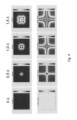
- Figure 4 gives an example of convolution kernels for amplitude and phase according to the Fourier-transformed defocus function (point 3.) for various focus absolute values. This concerns convolution kernels (25 ⁇ 25 pixels) for propagating wavefronts for amplitude (upper row) and phase (lower row) for various focus absolute values in ⁇ .
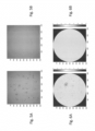
- Figure 5A indicates an example of a brightness distribution A ' 2 ( x , y ) in the camera plane, produced by punctiform amplitude disturbances (small dust grains) on an interferometer surface.
- Figure 5B shows the brightness distribution refocused computationally on the small dust grains.
- Figures 6A and 6B show the wavefronts in nm for the example from Figures 5A and 5B .
- the propagated wave O k " x y shows the sharpened image k of the coherent disturbances O l ( x, y ) on an interferometer surface l during measurement with a small ("punctiform") light source.
- the disturbances are usually caused by dust particles or damage on the surface (scratches).
- the disturbing wave thus carries more or less extensive punctiform or linear modulations in amplitude and/or phase.
- the corrected wave C k " x y is backpropagated ⁇ C k ′ x y into the camera plane.
- Figures 7A to 7D indicate an example of the processing of a wavefront which is measured with a small light source and which is covered by diffraction rings caused by punctiform particles on an interferometer surface.
- Figure 7A shows the measured wavefront
- Figure 7B shows the defocused wavefront
- Figure 7C shows the wavefront after filtering out the punctiform artefacts
- Figure 7D shows the corrected and back-focused wavefront.
- Figures 8A to 8D show the corresponding effects on the amplitude.
- Figure 8A shows the measured data fields
- Figure 8B shows the data fields defocused into the image shell of the causative surface.
- Figure 8C shows the data fields corrected in respect of the punctiform artefacts in Figure 8B .
- the corrected data fields are backpropagated into the camera plane.
- the surface artefacts are usually stationary artefacts which are imposed on the measured wavefront in the same way during all subsequent measurements.
- the corrected wavefront C' ( x, y ) can be formed from the measured wavefront O' ( x, y ):
- Figure 9 shows the beam path in the eyepiece camera region in the case of Figure 3 with punctiform disturbances on surface 4 in Figure 1 .
- the illustration shows marginal rays of the light source which combine in the surface image k behind the camera plane.
- the individual corrections ⁇ O k ′ x y in (10) were determined for a k ( x,y ) ⁇ 0 with a punctiform light source.
- the convolution kernel a k ( x,y ) required according to (11) and (12) is calculated in advance from ray tracing of the interferometer configuration and the chosen light source form for each surface image k.
- Figure 10 shows an example of a wavefront ( Figure 10A ) and amplitude ( Figure 10B ), which were measured with a large light source.
- the ring-shaped diffraction structures are distinctly blurred and damped in comparison with Figures 7A and 8A .
- Their correction is then effected by means of the sum of the individual corrections ⁇ O k ′ x y convolved according to (12).
- the proposed method ascertains and reduces the disturbances originating from individual interferometer surfaces in the measured wavefront.
- the method concentrates on punctiform and filamentary disturbances on the surfaces, e.g. small dust grains, scratches, damage.
- An exemplary method comprises:
- the method merely requires a calibration measurement with a small light source, which then provides the data sets required for the subsequent measurements with an arbitrarily extensive light source. As long as the beam path is not fundamentally changed and the artefacts on the surfaces remain unchanged, it is possible to use the data sets from the calibration measurement.
- the invention makes it possible to reduce coherent disturbances in the wavefront which originate from incomplete and/or contaminated interferometer surfaces.
- the invention also makes it possible, if appropriate, to reduce undesired specular reflection images of the light source.
- the noticeable outlay as a result of the proposed method consists in carrying out a calibration measurement and in lengthening the wavefront post-processing of the series measurement, which however usually does not have a significant impact.
Landscapes
- Physics & Mathematics (AREA)
- General Physics & Mathematics (AREA)
- Optics & Photonics (AREA)
- Analytical Chemistry (AREA)
- Chemical & Material Sciences (AREA)
- Geometry (AREA)
- Spectroscopy & Molecular Physics (AREA)
- Engineering & Computer Science (AREA)
- Health & Medical Sciences (AREA)
- Public Health (AREA)
- Epidemiology (AREA)
- Environmental & Geological Engineering (AREA)
- Signal Processing (AREA)
- Instruments For Measurement Of Length By Optical Means (AREA)
Abstract
Description
- The following disclosure is based on
German Patent Application No. 10 2022 209 477.8 filed on September 12, 2022 , which is incorporated into this application by reference. - The invention relates to a measurement method and to a measurement system for interferometrically determining a shape of an optical surface of a test object.
- One general field of application is the high-precision interferometric measurement of optical surfaces and optically transparent objects. One specific field of application is ultrahigh-precision interferometric measurement, such as is used e.g. during the production of lithographic projection optical units. That involves measurement uncertainties of less than 1/100 of the visible wavelength.
- Freeform surface mirrors or freeform lenses are increasingly being used in lithographic projection optical units. The rotary imparting method that can be applied to rotationally symmetrical aspheres is dispensed with in the interferometric testing of freeform surfaces owing to the asymmetry of the test object. Since the traditional calibration with rotary imparting of rotationally asymmetrical aberrations is not possible, an optical disturbance signal (speckle effects) remains which is produced inter alia by the surface fine structure of the interferometer components.
- One traditional means of minimizing or avoiding the coherent disturbances and artefacts caused by interferometer components is the use of a large light source. The latter ensures that fine structures on the components are imaged blurred, such that their coherent disturbing effects are damped. Large light sources can be used e.g. in two-beam interferometers of the "Michelson" or "Twyman-Green" type. Such types of interferometers are used rather rarely, however, owing to various constraints.
- The workhorse in the optics workshop, especially in the production of elements of lithographic projection optical units, is the "Fizeau" type of interferometer (Fizeau interferometer). A measurement system with a Fizeau interferometer comprises an illumination module which produces an effective light source. Light emitted by the illumination module is collimated by a collimator. A beam splitter is situated between the illumination module and the collimator. The collimated beam passes through a transparent reference element, the exit surface of which, manufactured with high optical quality, serves as a reference surface which reflects part of the light. The transmitted portion continues to propagate to the surface of the test object. The space between reference surface and surface of the test object is referred to as a cavity of the interferometer. The portion reflected by the surface of the test object contains information about the aberration caused by the test object. The wavefronts of both portions interfere in the interferometer and are guided via the beam splitter onto the sensor surface of a detector. A sharp image of the sample surface arises on the sensor surface, said image being pervaded with a stripe pattern (the interference pattern). In this case, a continuous stripe indicates regions with an identical air gap thickness. By contrast, adjacent stripes indicate a change in thickness corresponding to half the wavelength of the light.
- According to the rules of spatial coherence, the size of the light source must not exceed a specific size in order that interference images with sufficient contrast result.
- It has already been proposed to reduce coherent disturbances by using a circular light source (
DE 10 121 516 A1 corresponding toUS 2003/0030819 A1 ) or an arcuate light source (DE 10 2016 213 237 A1 corresponding toUS 2019/0154427 A1 ). - Another solution proposal provides a movable punctiform light source with temporally sequential recording and computation of the phase images (cf. e.g.
US 2012/0236316 A1 ). -
DE 10 2015 222 789 A1 describes a solution in which the illumination module has an additional module in the form of an upstream interferometer with an upstream cavity. - Against this background, the invention addresses the problem of reducing the influence of coherent disturbances on the measurement accuracy of interferometric measurements, without having to implement limitations in the design of light sources.
- In order to solve this problem, the invention provides a measurement method having the features of
Claim 1. Furthermore, a measurement system having the features ofClaim 7 is provided. Preferred developments are specified in the dependent claims. The wording of all the claims is incorporated by reference in the content of the description. - The measurement method can be carried out by any conventional measurement system which has the features of the preamble of
Claim 1. Special features reside in the manner of the evaluation and optionally the use of the measurement system. Interferometer surfaces are identified in the method. An interferometer surface is an optically effective surface of one of the optical components of the measurement system. Surface-related coherent wavefront disturbances are determined during the evaluation. Each of the wavefront disturbances is assigned to corresponding disturbing structures on one of the interferometer surfaces. The evaluation comprises a surface-specific subtraction of the surface-related coherent wavefront disturbances from the measured wavefront. A wavefront corrected in respect of coherent wavefront disturbances is ascertained as a result. This corrected wavefront can then be evaluated. Since coherent wavefront disturbances are then no longer present in the wavefront on which the evaluation is based, said wavefront represents with a better signal/noise ratio that sought wavefront which permits conclusions to be drawn from about the surface shape. - The measurement method proposed here does not require additional apparatus extensions of a conventional measurement system. Instead, a measurement method is provided in which the measured wavefront is computationally corrected in respect of coherent disturbances. In this case, it is e.g. unimportant whether use is made of a punctiform light source or an extensive light source whose size is limited by physically governed limitations.
- In accordance with one formulation, in essence the claimed invention thus provides for localizing and quantifying the coherent disturbances originating from individual interferometer surfaces, in order subsequently to subtract their effect from the measurement result. In contrast to the prior art, damping or averaging of unknown disturbances is not striven for here. A determination of origin, position and size of the individual disturbances is carried out instead.
- The term "coherent disturbance" can be understood as follows. A dust grain (as an example) on an arbitrary interferometer surface is generally not imaged sharply onto the camera (detector). Upon illumination, a "spherical wave" that is coherent with respect to the illuminating wave emanates from said dust grain. In the detector surface or on the camera, the "spherical wave" and the illuminating wave interfere and form a fine ring pattern. The latter is referred to as "coherent disturbance". When an extensive light source is used, each point of the light source forms a separate "coherent disturbance". Since each light source point is incoherent with respect to its neighbouring point, the "coherent disturbances" of each point add up incoherently on the camera. The ring patterns of all the points become blurred.
- In this application, the term "individual disturbance" denotes the coherent disturbances originating from an individual image of an individual interferometer surface.
- In accordance with one development, a computational propagation of the ascertained wavefront according to amplitude and phase is carried out. This has the effect that the surface-related disturbing structures of optically effective surfaces appear sharp in each case. These disturbing structures are then eliminated from amplitude and phase of the respective focused interferometer surface images. A backpropagation is then carried out, whereby a corrected wavefront is ascertained which no longer contains wavefront disturbances caused by the disturbing structures.
- During computational "focusing (propagation)" of the measured wavefront according to amplitude and phase, the fine ring pattern of the coherent disturbance becomes a sharp image of the dust grain. That can then be removed computationally (e.g. by means of median filters). The corrected wavefront is obtained after backpropagation.
- In order to provide the bases for the correction, in one preferred variant of the measurement method, a calibration measurement is carried out in which a quasi-punctiform effective light source is used. The individual corrections of the wavefront that originate from the interferometer surface images are determined on the basis of the results of the calibration measurement. A regular measurement is then carried out with the aid of an extensive effective light source whose relative brightness distribution is known. By computationally adapting the individual corrections of the wavefront to the known extensive effective light source, an overall wavefront correction can be ascertained. The latter is then subtracted from the measured wavefront to leave a corrected wavefront.
- The overall wavefront correction for the measurement with an extensive effective light source can be carried out by means of a computation of correction values ascertained with a punctiform effective light source with the aid of a convolution function representing the blurring effect of the extensive light source.
- The invention also relates to a measurement system for interferometrically determining a shape of an optical surface of a test object. The measurement system is configured for carrying out the measurement method. For this purpose, an evaluation unit is provided, inter alia, which has software loaded which enables the evaluation unit to carry out the calculations explained.
- Further advantages and aspects of the invention are evident from the claims and from the description of exemplary embodiments of the invention, which will be explained below with reference to the figures.
-
Figure 1 schematically shows a measurement system with a Fizeau interferometer; -
Figure 2 shows examples of coherent disturbances as a result of small particles on different optical surfaces of an interferometer in an intensity image (Figure 2A ) and in the wavefront (Figure 2B ); -
Figure 3 shows an example of the three imagings of a collimator surface relative to the CCD camera surface; -
Figure 4 shows an example of convolution kernels for amplitude and phase; -
Figure 5 shows, inFigure 5A , an example of measured intensity A′2(x,y) for amplitude artefacts on an interferometer surface and, inFigure 5B , an example of refocused intensity A"2(x,y) for amplitude artefacts on an interferometer surface; -
Figure 6 shows, inFigure 6A , a measured phase φ′(x, y) · λ/2π in nm for the example fromFigure 5A and, inFigure 6B , the calculated phase φ"(x,y)·λ/2π in nm for the example fromFigure 5B ; -
Figure 7 shows, inFigures 7A to 7D , an example of the processing of a wavefront which is measured with a small light source and which is covered by diffraction rings caused by punctiform particles on an interferometer surface; -
Figure 8 shows, inFigures 8A to 8D , the corresponding effects on the amplitude; -
Figure 9 shows the beam path of light source marginal rays in the eyepiece region in the case ofFigure 3 with small dust grains onsurface 4 inFigure 1 ; -
Figure 10 shows, inFigure 10A , an example of a wavefront and, inFigure 10B , an example of the amplitude, which were measured with a large light source, corresponding data sets with a small light source being indicated in association withFigures 7A and8A . - Hereinafter, theoretical principles of the invention will be explained and possibilities for practical implementation will be illustrated on the basis of exemplary embodiments.
-
Figure 1 schematically shows ameasurement system 100 from the prior art with a Fizeau interferometer for interferometrically determining the shape of anoptical surface 112 of atest object 110 held in a test object holder (not illustrated) - The
measurement system 100 comprises anillumination module 120 comprising a primarylight source 125, which generates measurement light having a measurement wavelength in the visible wavelength range, e.g. at a wavelength of approximately 532 nm, during operation. Optical elements of the illumination module serve for receiving the measurement light and for producing an extensive effectivelight source 130 in alight source plane 132 of the illumination module. - In the example in
Figure 1 , a laser is used as the primarylight source 125. A beam expandingoptical unit 127 disposed downstream generates an expanded laser beam, which is incident on arotating diffusing plate 128, where it forms a secondary light source in the form of a uniformly illuminated illumination spot having the desired size. This illumination spot, i.e. the secondary light source, functions as an effectivelight source 130 of the illumination module and emits measurement light in the direction of acollimator 210 or a collimationoptical unit 210, which is among the optical components of the interferometer. - The collimator is a collimation
optical unit 210 comprising one or more converging lenses, which serves for collimating the measurement light emitted by the effectivelight source 130 of the illumination module. Atransparent reference element 220 is situated at a distance behind thecollimator 210 in the parallelized beam path. Thereference element 220 has a front optical surface facing the collimator and a backoptical surface 222, which faces thesurface 112 of thetest object 110 and which serves as areference surface 222 for the measurement. Acavity 230 is formed between thereference surface 222 and thesurface 112 of thetest object 110; the distance between thesurface 112 of the test object and thereference surface 222 is the cavity length d. - A
beam splitter 240 in the form of a plane-parallel partly transmissive plane plate is arranged obliquely in the beam path between theillumination module 120 and thecollimator 210. Measurement light arriving from theillumination module 120 or from the effectivelight source 130 can pass through to the collimator. Measurement light reflected by thereference surface 222 and measurement light reflected by thesurface 112 of thetest object 110 are superimposed, impinge on thebeam splitter 240 from the side facing the collimator and are reflected in a superimposed manner in the direction of adetector 250. Thedetector 250 comprises aCCD camera 251 comprising aplanar sensor surface 252 ordetector surface 252 and comprising a cameraoptical unit 255 disposed upstream. The arrangement is implemented such that light source images of the effective light source arise at a distance upstream of the camera in anintermediate image plane 254, and are imaged onto thesensor surface 252 by means of the camera optical unit. An interferogram IF with interference stripes arises there. Astop 258 is arranged in theintermediate image plane 254. - The inventor has recognized certain fundamental limitations of such measurement systems from the prior art. These limitations will be explained firstly with reference to
Figure 1 . What is important, firstly, is primarily that the measurement light does not originate from a punctiform effective light source, but rather from an effectivelight source 130 having a certain extent or size in the light source plane, e.g. a diameter of the order of magnitude of one or more millimetres, depending on the focal length of the collimator, the cavity length and the wavelength. - According to the rules of spatial coherence, the size 2θ of the light source must not exceed a specific size if the intention is to generate interference images with sufficient contrast. Let parameter θ be the aperture angle at which half the effective light source appears from the
collimator 210. The following then holds true:
- In practice that restricts the possibility of suppressing high- and medium-frequency measurement errors which arise as a result of disturbing structures on interferometer components (e.g. as a result of roughness and surface defects, contaminants, bubbles and striations, etc.).
- These limitations can be overcome at least in part by using the teaching of the invention. The proposed method ascertains and reduces the disturbances originating from individual interferometer surfaces in the measured wavefront. This primarily involves punctiform and filamentary disturbances on the surfaces, e.g. small dust grains, scratches, damage. If appropriate, damping of unwanted reflection images of the light source can also be achieved.
Figures 2A and 2B show examples of coherent disturbances as a result of small particles on different optical surfaces of an interferometer in an intensity image (Figure 2A on the left) and in the wavefront (Figure 2B on the right). - In the exemplary embodiment explained below, the method comprises a measurement sequence with a small (quasi-punctiform) light source (calibration measurement) for computationally determining the individual corrections originating from the individual surface images, the regular measurements with an arbitrarily shaped and extensive light source with a relative brightness distribution, a computational correction of the wavefront ascertained with an extensive light source, and a subtraction of the calculated overall correction from the measured wavefront. During the calibration measurement, a conventional wavefront ascertainment is performed using a quasi-punctiform light source. The result contains all coherent disturbances caused by every interferometer surface.
- In one method variant, the method merely requires a calibration measurement with a small light source, which then provides the data sets required for the subsequent measurements with an arbitrarily extensive light source. As long as the beam path is not fundamentally changed and the artefacts on the surfaces remain unchanged, it is possible to use the data sets from the calibration measurement.
- Hereinafter, the underlying theory will be explained and examples will be given.
-
Figure 1 indicates aFizeau interferometer 100 by way of example, the optically effective surfaces (alternatively also referred to as "interferometer surfaces" in this application) of which are numbered using single- and double-digit numbers 1 to 17 in order to facilitate identification. These numbers are indicated in part in addition to the triple-digit reference signs. For each of the interferometer surfaces 1 to 16, by means of ray tracing, it is possible to calculate the image thereof after imaging through all the subsequent surfaces and to indicate the position and size relative to the camera plane or the detector plane 252 (corresponding to interferometer surface 17). - Consideration should be given to the multiple imagings of a surface by way of reflection at the reference surface and at the test object besides the directly observed image of the surface by means of the camera:
- 1) Surfaces which are observed after specular reflection at reference and test object and in addition directly by the camera (the
surfaces Figure 1 ) have three (3) images. - 2) Either such surfaces which have no direct image (surface 1) or the reference surface itself, which has only a direct image and specular reflection image at the test object, have/has two (2) images.
- 3) All eyepiece surfaces (surfaces 9 to 16) have one (1) image (direct imaging onto the camera).
- Table 1 below indicates the numbers of the interferometer surfaces from
Figure 1 and their number of images and coherent waves. In this case, the camera is set such that the test object (interferometer surface 7) is imaged sharply onto the camera surface or detector surface (interferometer surface 17). A differentiation between artefacts on the test object and the camera surface is then no longer possible. - The direct images during the return of the beams are coherently combined images since they arise as a result of illumination from the reference wave and the test object wave. Their interference structures are influenced by the cavity length d. Table 1 additionally indicates the number of coherent waves which lead to interference phenomena on the camera.
Table 1 Surface Designation Number of images Number of waves 1 Rear surface of splitter plate 2 2 2 Splitter surface 3 4 3 Collimator 3 4 4 Collimator 3 4 5 Rear surface of reference plate 3 4 6 Reference surface 2 2 7 Test object 1 1 8 Stop 1 2 9 Eyepiece surface 1 2 10 Eyepiece surface 1 2 11 Eyepiece surface 1 2 12 Eyepiece surface 1 2 13 Eyepiece surface 1 2 14 Eyepiece surface 1 2 15 Eyepiece surface 1 2 16 Eyepiece surface 1 2 17 Camera surface 1 1 - For explanation purposes,
Figure 3 shows imagings of thecollimator surface 4 relative to theCCD camera 17 for the Fizeau interferometer fromFigure 1 . In this case, the number 4' denotes the image of thesurface 4 after reflection at the test object, thenumber 4" denotes the image ofsurface 4 after reflection at the reference surface, and thenumber 4′′′ denotes the image of the surface upon direct imaging. - Two different variants are suitable for the propagation of a wavefront 0'(x,y) measured in the camera plane into the image surface of a selected interferometer surface:
- 1) calculation in Fourier space,
- 2) calculation in real space.
- More detailed explanations are given below. Let O(x,y) be the coherent disturbing wave to be determined that emanates from an interferometer surface


- For the propagation of O'(x, y) into the image surface of a selected interferometer surface, (4) is multiplied by the complex defocus function

- The defocus variable φd (u,v,x,y) is a function in u,v that is specific to each image point x,y. In the special case, it is identical for all x,y. For practical use, φd can be approximated by a quadratic function, e.g.


- From the formalism described above, it is possible to describe two computational methods (see A) and B) below) for calculating the propagated ("sharpened") wave O"(x, y) from the measured wave O'(x, y). A prerequisite is the knowledge of a defocus variable φd (u,v,x,y), which is
- a) either obtained from ray tracing or
- b) iteratively varied until the coherent disturbances appear sharp.
-
- 1. Determine amplitude A'(x,y) and phase φ′(x,y) in the camera plane from the interferometric measurement values,
- 2. Calculate complex field O'(x, y) = A'(x,y)e -iφ′(x,y),
- 3. Calculate Fourier transform

- 4. Multiply by defocus function

- 5. Inverse Fourier transformation

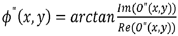
- 6. Calculate amplitude A"(x,y) = |O"(x, y)| and phase

-
- 1. Determine amplitude A'(x,y) and phase φ′(x,y) in the camera plane from the interferometric measurement values,
- 2. Calculate complex field O'(x, y) = A'(x,y)e -iφ′(x,y),
- 3. Convolve with the Fourier transform of the defocus function

- 4. Calculate amplitude A"(x,y) = |O"(x, y)| and phase
-
Figure 4 gives an example of convolution kernels for amplitude and phase according to the Fourier-transformed defocus function (point 3.) for various focus absolute values. This concerns convolution kernels (25 × 25 pixels) for propagating wavefronts for amplitude (upper row) and phase (lower row) for various focus absolute values in λ. -
Figure 5A indicates an example of a brightness distribution A'2(x,y) in the camera plane, produced by punctiform amplitude disturbances (small dust grains) on an interferometer surface.Figure 5B shows the brightness distribution refocused computationally on the small dust grains.Figures 6A and 6B show the wavefronts in nm for the example fromFigures 5A and 5B . - The propagated wave

- In order to eliminate same, tried and tested algorithms from image processing can be applied, for instance weighted median filters. In this case, a convolution operator is usually applied to the data fields of amplitude and phase.
- After the filtering, the wave

- The corrected wave


- The procedure is repeated for all K images of interferometer surfaces until all coherent surface corrections

- The procedure for determining the surface artefacts measured in the camera plane arises as follows:
- 1. Determine amplitude A'(x,y) and phase φ′(x,y) in the camera plane from the interferometric measurement values with a small ("punctiform") light source,
- 2. Calculate complex field O'(x, y) = A'(x,y)e -iφ'(x,y),
- 3. k = 1 to K (K is the number of images of interferometer surfaces with disturbances)
- a. Propagate O'(x,y) into the k-th surface image

- b. Remove coherent disturbances from amplitude image and phase image and calculate corrected wave

- c. Backpropagate into camera plane:

- d. Determine correction for surface k in camera plane

- a. Propagate O'(x,y) into the k-th surface image
-
Figures 7A to 7D indicate an example of the processing of a wavefront which is measured with a small light source and which is covered by diffraction rings caused by punctiform particles on an interferometer surface. In this case,Figure 7A shows the measured wavefront,Figure 7B shows the defocused wavefront,Figure 7C shows the wavefront after filtering out the punctiform artefacts, andFigure 7D shows the corrected and back-focused wavefront. -
Figures 8A to 8D show the corresponding effects on the amplitude.Figure 8A shows the measured data fields, andFigure 8B shows the data fields defocused into the image shell of the causative surface.Figure 8C shows the data fields corrected in respect of the punctiform artefacts inFigure 8B . InFigure 8D , the corrected data fields are backpropagated into the camera plane. - The surface artefacts are usually stationary artefacts which are imposed on the measured wavefront in the same way during all subsequent measurements.
- If measurement is still carried out with a small light source, then the corrected wavefront C'(x, y) can be formed from the measured wavefront O'(x, y):

- Accordingly, the sum of the effects of the surface artefacts is subtracted.
- With the use of an extensive light source, the corrections are no longer usable in this way. Instead, it is necessary to introduce a mathematical supplementation to transform the individual corrections

-
Figure 9 shows the beam path in the eyepiece camera region in the case ofFigure 3 with punctiform disturbances onsurface 4 inFigure 1 . The illustration shows marginal rays of the light source which combine in the surface image k behind the camera plane. The following relationship holds true for the projection ak (x,y) of the brightness distribution s(x,y) in the light source image onto the camera plane:
- bk
- distance between the surface image shell k and the camera plane,
- fOk
- focal length of the eyepiece,
- s(x,y)
- relative brightness distribution in the image of the light source,
- ak(x,y)
- projection of s(x,y) in the camera plane (light source projection) during imaging of the disturbances on surface image (image shell) k.
- The individual corrections


- The convolution kernel ak (x,y) required according to (11) and (12) is calculated in advance from ray tracing of the interferometer configuration and the chosen light source form for each surface image k.
-
Figure 10 shows an example of a wavefront (Figure 10A ) and amplitude (Figure 10B ), which were measured with a large light source. The ring-shaped diffraction structures are distinctly blurred and damped in comparison withFigures 7A and8A . Their correction is then effected by means of the sum of the individual corrections
- The proposed method ascertains and reduces the disturbances originating from individual interferometer surfaces in the measured wavefront. The method concentrates on punctiform and filamentary disturbances on the surfaces, e.g. small dust grains, scratches, damage.
- A further use could relate to undesired reflection images of the light source. Since each surface generates undesired specular reflection images of the light source despite antireflective coating, said images reaching the camera under certain circumstances, the proposed method could also play a part in damping said images. An exemplary method comprises:
- 1. a measurement sequence with a small light source (calibration measurement) for computationally determining the individual corrections

- 2. the regular measurements with an arbitrarily shaped and extensive light source with a relative brightness distribution s(x,y),
- 3. the computational correction of the measurements with an extensive light source by means of:
- a. forming the light source projections ak (x,y) for each of the K image shells according to equ. (11),
- b. calculating the individual corrections

- c. subtracting the overall correction from the measured wavefront O'(x, y) according to equ. (12).
- The method merely requires a calibration measurement with a small light source, which then provides the data sets required for the subsequent measurements with an arbitrarily extensive light source. As long as the beam path is not fundamentally changed and the artefacts on the surfaces remain unchanged, it is possible to use the data sets from the calibration measurement.
- The invention makes it possible to reduce coherent disturbances in the wavefront which originate from incomplete and/or contaminated interferometer surfaces.
- The invention also makes it possible, if appropriate, to reduce undesired specular reflection images of the light source.
- In this case, it is necessary to obtain the required calibration data sets from a measurement with a small light source, which are then applied to subsequent measurements with an arbitrarily shaped, extensive light source.
- It is not necessary to expend additional outlay in respect of apparatus, such as e.g. the provision of an extensive light source or an upstream cavity.
- In the series measurement, it is not necessary to expend an increased acquisition time, for instance by recording and imparting a plurality of wavefronts with the position of the light source being changed.
- The noticeable outlay as a result of the proposed method consists in carrying out a calibration measurement and in lengthening the wavefront post-processing of the series measurement, which however usually does not have a significant impact.
Claims (7)
- Measurement method for interferometrically determining a shape of an optical surface (112) of a test object (110) by means of a measurement system (100) comprising:an illumination module (120) for producing an effective light source (130) in a light source plane (132) of the illumination module;optical components comprising:a collimator (210) for collimating the measurement light emitted by the effective light source (130);a transparent reference element (220) disposed downstream of the collimator (210) and having a reference surface (222) facing the surface (112) of the test object (110), a cavity (230) being formed between the reference surface (222) and the surface (112) of the test object (110);a beam splitter (240) arranged between the illumination module (120) and the collimator (210) in such a way that measurement light emitted by the effective light source (130) passes through to the collimator (210) or is reflected and measurement light reflected by the reference surface (222) and the surface (112) of the test object (110) is reflected in a superimposed manner in the direction of a detector (250) or is transmitted; the measurement method comprisinga measurement of a surface of the test object in order to ascertain a measured wavefront present in a detector surface of the detector, andan evaluation of the wavefront in order to determine the shape of the optical surface,characterized in that the evaluation comprises the following steps:identifying interferometer surfaces, an interferometer surface being an optically effective surface of one of the optical components of the measurement system that is used at least once during a measurement;determining surface-related coherent wavefront disturbances and assigning each of the wavefront disturbances to disturbing structures on one of the interferometer surfaces of the measurement system;ascertaining a wavefront corrected in respect of coherent wavefront disturbances by surface-specific subtraction of the surface-related coherent wavefront disturbances from the measured wavefront;evaluating the corrected wavefront.
- Measurement method according to Claim 1, characterized in that the following steps are carried out for each of the interferometer surfaces:computational propagation of the ascertained wavefront according to amplitude and phase, such that the surface-related disturbing structures of optically effective surfaces appear sharp;eliminating the disturbing structures from amplitude and phase of the respective focused interferometer surface image;backpropagation in order to ascertain a wavefront corrected in respect of wavefront disturbances caused by the disturbing structures.
- Measurement method according to Claim 1 or 2, characterized in that in order to eliminate images of the disturbing structures at least one algorithm from image processing is applied, in particular weighted median filters and/or the application of a convolution operator to the data fields of amplitude and phase.
- Measurement method according to any of the preceding claims, characterized in that when ascertaining interferometer surface images for one or a plurality of interferometer surfaces a plurality of interferometer surface images are calculated.
- Measurement method according to any of the preceding claims, characterized by the following steps:carrying out a calibration measurement using a quasi-punctiform effective light source;determining the individual corrections of the wavefront that originate from the interferometer surface images on the basis of the calibration measurement;carrying out a regular measurement with an extensive effective light source with a known relative brightness distribution;computationally adapting the individual corrections of the wavefront to the known extensive effective light source in order to ascertain an overall wavefront correction;subtracting the overall wavefront correction from the measured wavefront.
- Measurement method according to Claim 5, characterized by a computation of correction values ascertained with a punctiform effective light source with a convolution function representing the blurring effect of the extensive light source.
- Measurement system (100) for interferometrically determining a shape of an optical surface (112) of a test object (110), comprising:an illumination module (120) for producing an effective light source (130) in a light source plane (132) of the illumination module;optical components comprising:a collimator (210) for collimating the measurement light emitted by the effective light source (130);a transparent reference element (220) disposed downstream of the collimator (210) and having a reference surface (222) facing the surface (112) of the test object (110), a cavity (230) being formed between the reference surface (222) and the surface (112) of the test object (110);a beam splitter (240) arranged between the illumination module (120) and the collimator (210) in such a way that measurement light emitted by the effective light source (130) passes through to the collimator (210) or is reflected and measurement light reflected by the reference surface (222) and the surface (112) of the test object (110) is reflected in a superimposed manner in the direction of a detector (250) or is transmitted;characterized in thatthe measurement system is configured for carrying out a measurement of the optical surface of the test object in order to ascertain a measured waveform present in a detector surface of the detector and an evaluation of the wavefront in order to determine the shape of the optical surface in accordance with the measurement method according to any of Claims 1 to 6.
Applications Claiming Priority (1)
| Application Number | Priority Date | Filing Date | Title |
|---|---|---|---|
| DE102022209477.8A DE102022209477B3 (en) | 2022-09-12 | 2022-09-12 | Interferometric measuring method and interferometric measuring device |
Publications (1)
| Publication Number | Publication Date |
|---|---|
| EP4336138A1 true EP4336138A1 (en) | 2024-03-13 |
Family
ID=87760387
Family Applications (1)
| Application Number | Title | Priority Date | Filing Date |
|---|---|---|---|
| EP23192364.0A Pending EP4336138A1 (en) | 2022-09-12 | 2023-08-21 | Interferometric measurement method and interferometric measurement system |
Country Status (3)
| Country | Link |
|---|---|
| EP (1) | EP4336138A1 (en) |
| CN (1) | CN117685872A (en) |
| DE (1) | DE102022209477B3 (en) |
Citations (4)
| Publication number | Priority date | Publication date | Assignee | Title |
|---|---|---|---|---|
| US20030030819A1 (en) | 2001-05-03 | 2003-02-13 | Michael Kuechel | Apparatus and method(s) for reducing the effects of coherent artifacts in an interferometer |
| US20120236316A1 (en) | 2011-02-18 | 2012-09-20 | Carl Zeiss Smt Gmbh | Method and apparatus for determining a shape of an optical test surface |
| DE102015222789A1 (en) | 2014-12-11 | 2016-06-16 | Carl Zeiss Smt Gmbh | Interferometric measurement of an optical surface |
| DE102016213237A1 (en) | 2016-07-20 | 2018-01-25 | Carl Zeiss Smt Gmbh | Measuring device for the interferometric determination of a shape of an optical surface |
Family Cites Families (1)
| Publication number | Priority date | Publication date | Assignee | Title |
|---|---|---|---|---|
| DE102007056200A1 (en) * | 2007-11-21 | 2009-05-28 | Mathias Dr. Beyerlein | Assembly for testing surfaces, by interferometry, directs pairs of beams with orthogonal polarization at reference and test surfaces for a reflected pair to be deflected to a receiver for phase-shift evaluation |
-
2022
- 2022-09-12 DE DE102022209477.8A patent/DE102022209477B3/en active Active
-
2023
- 2023-08-21 EP EP23192364.0A patent/EP4336138A1/en active Pending
- 2023-09-11 CN CN202311174735.1A patent/CN117685872A/en active Pending
Patent Citations (5)
| Publication number | Priority date | Publication date | Assignee | Title |
|---|---|---|---|---|
| US20030030819A1 (en) | 2001-05-03 | 2003-02-13 | Michael Kuechel | Apparatus and method(s) for reducing the effects of coherent artifacts in an interferometer |
| US20120236316A1 (en) | 2011-02-18 | 2012-09-20 | Carl Zeiss Smt Gmbh | Method and apparatus for determining a shape of an optical test surface |
| DE102015222789A1 (en) | 2014-12-11 | 2016-06-16 | Carl Zeiss Smt Gmbh | Interferometric measurement of an optical surface |
| DE102016213237A1 (en) | 2016-07-20 | 2018-01-25 | Carl Zeiss Smt Gmbh | Measuring device for the interferometric determination of a shape of an optical surface |
| US20190154427A1 (en) | 2016-07-20 | 2019-05-23 | Carl Zeiss Smt Gmbh | Measuring device for interferometric determination of a shape of an optical surface |
Also Published As
| Publication number | Publication date |
|---|---|
| DE102022209477B3 (en) | 2024-01-04 |
| CN117685872A (en) | 2024-03-12 |
Similar Documents
| Publication | Publication Date | Title |
|---|---|---|
| US8593642B2 (en) | Method of measuring a shape of an optical surface based on computationally combined surface region measurements and interferometric measuring device | |
| JP5444334B2 (en) | Interference defect detection and classification | |
| CN101495833B (en) | Method and apparatus for determining the deviation of the actual shape of an optical surface from an ideal shape | |
| US5835217A (en) | Phase-shifting point diffraction interferometer | |
| US7831105B2 (en) | Method for determining the image quality of an optical imaging system | |
| US10527403B2 (en) | Measuring device for interferometric determination of a shape of an optical surface | |
| TWI845952B (en) | Method for determining an imaging quality of an optical system when illuminated by illumination light within an entrance pupil to be measured | |
| US7336371B1 (en) | Apparatus and method for measuring the wavefront of an optical system | |
| JP2022183107A (en) | Method for determining imaging quality of optical system under illumination by illuminating light in measured pupil | |
| US20030030819A1 (en) | Apparatus and method(s) for reducing the effects of coherent artifacts in an interferometer | |
| JPH0666537A (en) | System error measuring method and shape measuring apparatus using the same | |
| JP2019500616A (en) | Method and apparatus for optimizing the optical performance of an interferometer | |
| CN116670499A (en) | Use the correction plate to correct the aberrations and traces of the optical system | |
| US5737081A (en) | Extended-source low coherence interferometer for flatness testing | |
| US10365164B2 (en) | Optical system phase acquisition method and optical system evaluation method | |
| JP2018021891A (en) | Method of acquiring phase of optical system and method of evaluating optical system | |
| Rubin | Scatterplate interferometry | |
| Abdelsalam et al. | Digital holographic shape measurement using Fizeau microscopy | |
| JP3146590B2 (en) | Shape measuring method and shape measuring system | |
| EP1384044B1 (en) | Reducing coherent artifacts in an interferometer | |
| Echter et al. | Carrier fringe analysis algorithms for three degree of freedom optical probing | |
| CN117685872A (en) | Interferometry methods and interferometry systems | |
| Kebbel et al. | Characterization of aspherical micro-optics using digital holography: improvement of accuracy | |
| Freischlad et al. | Speckle reduction by virtual spatial coherence | |
| JP2025541843A (en) | Telecentric interferometer, method for determining characteristics of an incident light field, and interferometer assembly - Patents.com |
Legal Events
| Date | Code | Title | Description |
|---|---|---|---|
| PUAI | Public reference made under article 153(3) epc to a published international application that has entered the european phase |
Free format text: ORIGINAL CODE: 0009012 |
|
| STAA | Information on the status of an ep patent application or granted ep patent |
Free format text: STATUS: THE APPLICATION HAS BEEN PUBLISHED |
|
| AK | Designated contracting states |
Kind code of ref document: A1 Designated state(s): AL AT BE BG CH CY CZ DE DK EE ES FI FR GB GR HR HU IE IS IT LI LT LU LV MC ME MK MT NL NO PL PT RO RS SE SI SK SM TR |
|
| STAA | Information on the status of an ep patent application or granted ep patent |
Free format text: STATUS: REQUEST FOR EXAMINATION WAS MADE |
|
| 17P | Request for examination filed |
Effective date: 20240708 |
|
| RBV | Designated contracting states (corrected) |
Designated state(s): AL AT BE BG CH CY CZ DE DK EE ES FI FR GB GR HR HU IE IS IT LI LT LU LV MC ME MK MT NL NO PL PT RO RS SE SI SK SM TR |
|
| STAA | Information on the status of an ep patent application or granted ep patent |
Free format text: STATUS: EXAMINATION IS IN PROGRESS |
|
| 17Q | First examination report despatched |
Effective date: 20251017 |