EP4336115A1 - Indoor unit and air conditioning device - Google Patents
Indoor unit and air conditioning device Download PDFInfo
- Publication number
- EP4336115A1 EP4336115A1 EP22798963.9A EP22798963A EP4336115A1 EP 4336115 A1 EP4336115 A1 EP 4336115A1 EP 22798963 A EP22798963 A EP 22798963A EP 4336115 A1 EP4336115 A1 EP 4336115A1
- Authority
- EP
- European Patent Office
- Prior art keywords
- indoor
- drain pump
- drain
- state
- control unit
- Prior art date
- Legal status (The legal status is an assumption and is not a legal conclusion. Google has not performed a legal analysis and makes no representation as to the accuracy of the status listed.)
- Granted
Links
Images




Classifications
-
- F—MECHANICAL ENGINEERING; LIGHTING; HEATING; WEAPONS; BLASTING
- F24—HEATING; RANGES; VENTILATING
- F24F—AIR-CONDITIONING; AIR-HUMIDIFICATION; VENTILATION; USE OF AIR CURRENTS FOR SCREENING
- F24F11/00—Control or safety arrangements
- F24F11/70—Control systems characterised by their outputs; Constructional details thereof
-
- F—MECHANICAL ENGINEERING; LIGHTING; HEATING; WEAPONS; BLASTING
- F24—HEATING; RANGES; VENTILATING
- F24F—AIR-CONDITIONING; AIR-HUMIDIFICATION; VENTILATION; USE OF AIR CURRENTS FOR SCREENING
- F24F13/00—Details common to, or for air-conditioning, air-humidification, ventilation or use of air currents for screening
- F24F13/22—Means for preventing condensation or evacuating condensate
- F24F13/222—Means for preventing condensation or evacuating condensate for evacuating condensate
-
- F—MECHANICAL ENGINEERING; LIGHTING; HEATING; WEAPONS; BLASTING
- F24—HEATING; RANGES; VENTILATING
- F24F—AIR-CONDITIONING; AIR-HUMIDIFICATION; VENTILATION; USE OF AIR CURRENTS FOR SCREENING
- F24F1/00—Room units for air-conditioning, e.g. separate or self-contained units or units receiving primary air from a central station
- F24F1/0007—Indoor units, e.g. fan coil units
- F24F1/0043—Indoor units, e.g. fan coil units characterised by mounting arrangements
- F24F1/0047—Indoor units, e.g. fan coil units characterised by mounting arrangements mounted in the ceiling or at the ceiling
-
- F—MECHANICAL ENGINEERING; LIGHTING; HEATING; WEAPONS; BLASTING
- F24—HEATING; RANGES; VENTILATING
- F24F—AIR-CONDITIONING; AIR-HUMIDIFICATION; VENTILATION; USE OF AIR CURRENTS FOR SCREENING
- F24F11/00—Control or safety arrangements
- F24F11/62—Control or safety arrangements characterised by the type of control or by internal processing, e.g. using fuzzy logic, adaptive control or estimation of values
- F24F11/63—Electronic processing
-
- F—MECHANICAL ENGINEERING; LIGHTING; HEATING; WEAPONS; BLASTING
- F24—HEATING; RANGES; VENTILATING
- F24F—AIR-CONDITIONING; AIR-HUMIDIFICATION; VENTILATION; USE OF AIR CURRENTS FOR SCREENING
- F24F2140/00—Control inputs relating to system states
- F24F2140/20—Heat-exchange fluid temperature
-
- F—MECHANICAL ENGINEERING; LIGHTING; HEATING; WEAPONS; BLASTING
- F24—HEATING; RANGES; VENTILATING
- F24F—AIR-CONDITIONING; AIR-HUMIDIFICATION; VENTILATION; USE OF AIR CURRENTS FOR SCREENING
- F24F2140/00—Control inputs relating to system states
- F24F2140/50—Load
Definitions
- the present disclosure relates to an indoor unit, and an air conditioner.
- An air conditioner disclosed in Patent Literature 1 JP H07-332743 A ) includes a mechanism in which drain water generated in an evaporator is received into a drain pan, and the drain water in the drain pan is discharged using a drain pump.
- the air conditioner starts operation of the drain pump when a water level of the drain water in the drain pan becomes equal to or higher than a height of a water suction port of the drain pump, and stops the operation of the drain pump when the water level of the drain water becomes equal to or lower than the height of the water suction port of the drain pump.
- An indoor unit is used in an air conditioner capable of executing a cooling operation by circulating a refrigerant.
- the indoor unit includes a heat exchanger, a drain pan, a drain pump, and a control unit.
- the heat exchanger exchanges heat between the refrigerant and indoor air.
- the drain pan receives water generated in the heat exchanger.
- the drain pump sucks up the water from the drain pan.
- the control unit performs a first control at a time of executing the cooling operation. In the first control, the control unit operates the drain pump when an evaporation temperature of the refrigerant in the heat exchanger is equal to or lower than a dew point temperature of the indoor air. In the first control, the control unit controls the drain pump so as to have a period in which operation of the drain pump is not performed when the evaporation temperature is higher than the dew point temperature.
- the indoor unit controls the drain pump so as to have the period in which operation of the drain pump is not performed in a case where the amount of the water generated in the heat exchanger is small. Accordingly, power consumption of the drain pump is suppressed.
- An indoor unit is the indoor unit according to the first aspect, wherein, in a first control, the control unit continues the operation of the drain pump for a predetermined period from a time point of transition from a state in which the evaporation temperature is equal to or lower than the dew point temperature to a state in which the evaporation temperature is higher than the dew point temperature, and thereafter stops the operation of the drain pump.
- An indoor unit is the indoor unit according to the first or second aspect, wherein, at the time of executing the cooling operation, the control unit continues the operation of the drain pump in a case of detecting an abnormality in a first sensor for acquiring the evaporation temperature or a second sensor for acquiring the dew point temperature.
- An indoor unit is the indoor unit according to any one of the first to third aspects, wherein, at the time of executing the cooling operation, the control unit continues the operation of the drain pump in a first state.
- the control unit performs, at the time of executing the cooling operation, the first control in a second state, in which a load on the air conditioner at the time of executing the cooling operation is smaller than that in the first state.
- the indoor unit constantly operates the drain pump in a case where the load on the air conditioner is large and the amount of the water generated in the heat exchanger is large.
- the indoor unit controls the drain pump so as to have the period in which operation of the drain pump is not performed in a case where the load on the air conditioner is small and the amount of the water generated in the heat exchanger is small. As a result, leakage of the water due to a rapid rise in the water level of the drain pan is suppressed, and the power consumption of the drain pump is suppressed.
- An air conditioner according to a fifth aspect includes the indoor unit according to any one of the first to fourth aspects.
- An indoor unit is used in an air conditioner capable of executing a cooling operation by circulating a refrigerant.
- the indoor unit includes a heat exchanger, a drain pan, a drain pump, and a control unit.
- the heat exchanger exchanges heat between the refrigerant and indoor air.
- the drain pan receives water generated in the heat exchanger.
- the drain pump sucks up the water from the drain pan.
- the control unit controls the drain pump such that an operation start condition of the drain pump in a first state and an operation start condition of the drain pump in a second state are different from each other.
- the second state is a state in which a load on the air conditioner at the time of executing the cooling operation is smaller than that in the first state.
- the indoor unit changes the operation start condition of the drain pump according to the load on the air conditioner at the time of executing the cooling operation. For example, in a case where the load on the air conditioner is small and the amount of the water generated in the heat exchanger is small, the indoor unit does not start operation of the drain pump until a water level of the drain pan reaches a predetermined height. Accordingly, power consumption of the drain pump is suppressed.
- An indoor unit is the indoor unit according to the sixth aspect, wherein, at the time of executing the cooling operation, the control unit continues operation of the drain pump in the first state. At the time of executing the cooling operation, in the second state, the control unit starts the operation of the drain pump when a water level of the drain pan rises to reach a predetermined height, and stops the operation of the drain pump when the water level of the drain pan falls below the predetermined height.
- the indoor unit constantly operates the drain pump in a case where the load on the air conditioner is large and the amount of the water generated in the heat exchanger is large.
- the indoor unit stops the operation of the drain pump when the water level of the drain pan falls below the predetermined height. As a result, leakage of the water due to a rapid rise in the water level of the drain pan is suppressed, and the power consumption of the drain pump is suppressed.
- An indoor unit according to an eighth aspect is the indoor unit according to the seventh aspect, wherein the predetermined height is higher than a height of a water suction port of the drain pump.
- the indoor unit starts the operation of the drain pump after the water level of the drain pan exceeds the height of the water suction port of the drain pump in a case where the amount of the water generated in the heat exchanger is small. Accordingly, power consumption of the drain pump is suppressed.
- An indoor unit is the indoor unit according to any one of the sixth to eighth aspects, wherein the second state includes a state in which an evaporation temperature of the refrigerant in the heat exchanger is higher than a dew point temperature of the indoor air, or a state in which a difference between the evaporation temperature and the dew point temperature is smaller than a predetermined value in a case where the evaporation temperature is equal to or lower than the dew point temperature.
- the indoor unit determines the amount of the water generated in the heat exchanger from the evaporation temperature of the refrigerant in the heat exchanger and the dew point temperature of the indoor air. Since the evaporation temperature and the dew point temperature can be measured using a conventional sensor, cost is suppressed.
- An air conditioner according to a tenth aspect includes the indoor unit according to any one of the sixth to ninth aspects.
- An indoor unit is used in an air conditioner capable of executing a cooling operation by circulating a refrigerant.
- the indoor unit includes a heat exchanger, a drain pan, a drain pump, and a control unit.
- the heat exchanger exchanges heat between the refrigerant and indoor air.
- the drain pan receives water generated in the heat exchanger.
- the drain pump sucks up the water from the drain pan.
- the control unit performs a first control at a time of executing the cooling operation. In the first control, when a water level of the drain pan rises to reach a first height, the control unit starts operation of the drain pump.
- the control unit stops a compressor of the air conditioner while continuing the operation of the drain pump.
- the control unit stops the operation of the drain pump.
- the first height is higher than a height of a water suction port of the drain pump.
- the indoor unit starts the operation of the drain pump when the water level of the drain pan reaches a predetermined height, and stops the operation of the drain pump when the water level of the drain pan falls below the predetermined height. Accordingly, power consumption of the drain pump is suppressed.
- An indoor unit is the indoor unit according to the eleventh aspect, wherein, at the time of executing the cooling operation, the control unit continues the operation of the drain pump in a first state.
- the control unit performs, at the time of executing the cooling operation, the first control in a second state, in which a load on the air conditioner at the time of executing the cooling operation is smaller than that in the first state.
- the indoor unit constantly operates the drain pump in a case where the load on the air conditioner is large and the amount of the water generated in the heat exchanger is large.
- the indoor unit stops the operation of the drain pump when the water level of the drain pan falls below the predetermined height.
- An indoor unit is the indoor unit according to the twelfth aspect, wherein the second state includes a state in which an evaporation temperature of the refrigerant in the heat exchanger is higher than a dew point temperature of the indoor air, or a state in which a difference between the evaporation temperature and the dew point temperature is smaller than a predetermined value in a case where the evaporation temperature is equal to or lower than the dew point temperature.
- the indoor unit determines the amount of the water generated in the heat exchanger from the evaporation temperature of the refrigerant in the heat exchanger and the dew point temperature of the indoor air. Since the evaporation temperature and the dew point temperature can be measured using a conventional sensor, cost is suppressed.
- An indoor unit according to a fourteenth aspect is the indoor unit according to any one of the eleventh to thirteenth aspects, wherein the first height is equal to or less than an intermediate height between the height of the water suction port and the second height.
- the water level of the drain pan which is a condition for starting the operation of the drain pump, is set near the water suction port of the drain pump. As a result, leakage of the water due to a rapid rise in the water level of the drain pan is suppressed.
- An air conditioner according to a fifteenth aspect includes the indoor unit according to any one of the eleventh to fourteenth aspects.
- the air conditioner 10 is a refrigerant pipe-scheme air conditioner, and heats and cools each room in a building by executing a vapor compression refrigeration cycle operation.
- the air conditioner 10 includes an outdoor unit 11, an indoor unit 12, a liquid-refrigerant connection pipe 13, and a gas-refrigerant connection pipe 14.
- the outdoor unit 11 and the indoor unit 12 are connected via the liquid-refrigerant connection pipe 13 and the gas-refrigerant connection pipe 14.
- a refrigerant sealed in the refrigerant circuit circulates.
- the air conditioner 10 performs a refrigeration cycle operation in which the refrigerant is compressed, radiates heat (condensed), decompressed, absorbs heat (evaporated), and then compressed again in the refrigerant circuit.
- the outdoor unit 11 is disposed outside the building, in a basement of the building, or the like.
- the outdoor unit 11 mainly includes a compressor 20, a four-way switching valve 15, an outdoor heat exchanger 30, an outdoor expansion valve 41, an outdoor fan 35, a liquid-side shutoff valve 17, a gas-side shutoff valve 18, an accumulator 25, and an outdoor control unit 91.
- the indoor unit 12 is installed in a ceiling space 80 located above a ceiling 81 of each room.
- the indoor unit 12 is an indoor unit of a type to be installed by being built in the ceiling 81.
- the indoor unit 12 mainly includes a casing 22, a wind direction changing member 39, an indoor heat exchanger 50, an indoor fan 55, a bell mouth 56, a drain pan 57, a drain pump 59, and an indoor control unit 92.
- the air conditioner 10 has a decentralized configuration in which the plurality of indoor units 12 are connected to one outdoor unit 11. However, for example, the air conditioner 10 may have a configuration in which one indoor unit 12 is connected to one outdoor unit 11.
- the indoor heat exchanger 50 functions as a heat absorber (evaporator) or a radiator (condenser) for the refrigerant.
- the indoor heat exchanger 50 functions as the heat absorber.
- the indoor heat exchanger 50 functions as the radiator.
- the outdoor control unit 91 is a computer that controls components of the outdoor unit 11.
- the indoor control unit 92 is a computer that controls components of the indoor unit 12.
- Each of the outdoor control unit 91 and the indoor control unit 92 mainly includes an arithmetic device and a storage device.
- the arithmetic device is, for example, a CPU or a GPU.
- the arithmetic device reads a program stored in the storage device and performs predetermined arithmetic processing in accordance with the program.
- the arithmetic device writes a result of the arithmetic processing in the storage device and reads information stored in the storage device in accordance with the program.
- the outdoor control unit 91 is connected to the indoor control unit 92 via a communication line to transmit and receive data, a control signal, and the like.
- the liquid-refrigerant connection pipe 13 and the gas-refrigerant connection pipe 14 are refrigerant pipes laid on site when the outdoor unit 11 and the indoor unit 12 are installed in the building. As illustrated in FIG. 2 , the liquid-refrigerant connection pipe 13 and the gas-refrigerant connection pipe 14 pass through the ceiling space 80.
- the casing 22 mainly includes a casing main body 22a and a face panel 22b.
- the casing main body 22a is disposed so as to be inserted into an opening 81a formed in the ceiling 81 of each room.
- the casing main body 22a is a substantially octagonal box-shaped body in which long sides and short sides are alternately formed in a planar view, and a lower surface thereof is opened.
- the casing main body 22a has a top panel, and a plurality of side plates extending downward from a peripheral edge of the top panel.
- the face panel 22b is disposed so as to be fitted into the opening 81a of the ceiling 81.
- the face panel 22b extends further to an outside than the top panel and the side plates of the casing main body 22a in the planar view, and is attached to a lower part of the casing main body 22a from an indoor side.
- the face panel 22b includes an inner frame 23a and an outer frame 23b provided outside the inner frame 23a in the planar view.
- a suction port 36 having a substantially quadrangular shape in the planar view opened downward.
- a blow-out port 37 opened in a range from a downward direction to a diagonally downward direction and a corner blow-out port 38.
- a filter 34 is provided above the suction port 36 to remove dust from air sucked through the suction port 36.
- the blow-out port 37 includes a first blow-out port 37a, a second blow-out port 37b, a third blow-out port 37c, and a fourth blow-out port 37d. These blow-out ports are provided between the inner frame 23a and the outer frame 23b so as to extend in parallel with respective sides of the suction port 36 having a substantially quadrangular shape in the planar view.
- the corner blow-out port 38 includes a first corner blow-out port 38a, a second corner blow-out port 38b, a third corner blow-out port 38c, and a fourth corner blow-out port 38d. These corner blow-out ports are provided at four corners of a place between the inner frame 23a and the outer frame 23b in the planar view.
- the wind direction changing member 39 is attached to a lower surface of the casing main body 22a.
- the wind direction changing member 39 is a member that can change a direction of air flow passing through the blow-out port 37.
- the wind direction changing member 39 includes a first wind direction changing member 39a disposed at the first blow-out port 37a, a second wind direction changing member 39b disposed at the second blow-out port 37b, a third wind direction changing member 39c disposed at the third blow-out port 37c, and a fourth wind direction changing member 39d disposed at the fourth blow-out port 37d.
- Each of the wind direction changing members 39a to 39d includes a flap main body and an arm Z.
- the flap main body is a plate-shaped member having a concave surface X having a concave cross-sectional shape perpendicular to a rotational axis, and a convex surface Y on a back side of the concave surface X and having a convex cross-sectional shape perpendicular to the rotational axis.
- the concave surface X is a surface facing an upstream side of the blow-out port 37 when the air conditioner 10 is stopped, and includes a plurality of knurls extending in a longitudinal direction.
- the convex surface Y is a surface facing to a lower side, which is an indoor space side, at a time of stopping, and has a smooth face surface.
- the arm Z is secured to a side of the flap main body provided with the concave surface X.
- An end of the arm Z opposite to the flap main body is pivotally supported so as to be rotatable via a drive shaft with respect to a structural component extending from an interior of the indoor unit 3.
- Each of the drive shafts extends along the longitudinal direction of each of the blow-out ports 37a to 37d in the planar view.
- the wind direction changing member 39 includes a not-illustrated stepping motor connected to an end of the corresponding drive shaft. The flap main body and the arm Z receive a driving force from the motor to rotate via the drive shaft, thereby changing a wind direction.
- a posture of the wind direction changing member 39 is controlled so that the wind direction changing member 39 may have a plurality of kinds of predetermined angles determined in advance according to a degree of rotation of the drive shaft.
- air passing through the upstream side of the blow-out port 37 mainly hits the concave surface X of the flap main body.
- the respective postures of the first wind direction changing member 39a, the second wind direction changing member 39b, the third wind direction changing member 39c, and the fourth wind direction changing member 39d are independently controlled by the indoor control unit 92.
- the indoor control unit 92 drives the drive shaft to cause the posture of the wind direction changing member 39 to be controlled.
- the indoor heat exchanger 50 is a heat exchanger that is disposed inside the casing main body 22a in a bent state so as to surround the indoor fan 55 in the planar view. More specifically, the indoor heat exchanger 50 includes multiple heat transfer fins arranged at predetermined spaces, and a plurality of heat transfer tubes penetrating the heat transfer fins in a thickness direction. A liquid side of the indoor heat exchanger 50 is connected to an end of the liquid-refrigerant connection pipe 13, and a gas side of the indoor heat exchanger 50 is connected to an end of the gas-refrigerant connection pipe 14.
- the indoor fan 55 is a centrifugal fan arranged inside the casing main body 22a.
- the indoor fan 55 forms an air flow where indoor air is sucked into the casing 22 through the suction port 36 of the face panel 22b, passes through the indoor heat exchanger 50, and is then blown out of the casing 22 through the blow-out port 37 of the face panel 22b.
- the indoor fan 55 includes a fan motor 55a provided at a center of the top panel of the casing main body 22a and an impeller connected to the fan motor 55a and rotationally driven.
- the impeller is an impeller having a turbo blade, and can suck air into the impeller from below and blow out the air toward an outer peripheral side of the impeller in the planar view by rotating about a rotational axis O.
- the number of rotations of the indoor fan 55 is controlled by the indoor control unit 92 to enable air volume to be controlled in a plurality of levels.
- the drain pan 57 is disposed below the indoor heat exchanger 50, and receives drain water generated by condensation of moisture contained in air at the indoor heat exchanger 50.
- the drain pan 57 is attached to a lower portion of the casing main body 22a.
- the drain pan 57 is provided with a cylindrical space extending in an up-down direction inside the indoor heat exchanger 50 in the planar view.
- the bell mouth 56 is disposed on a lower side inside the space.
- the bell mouth 56 is a member for guiding air sucked from the suction port 36 to the indoor fan 55, and has a flat portion extending horizontally and a cylindrical portion extending in the up-down direction around a center.
- the drain pan 57 includes a plurality of blow-out channels 47 extending in the up-down direction outside the indoor heat exchanger 50 in the planar view.
- the blow-out channels 47 have a first blow-out channel communicating with the first blow-out port 37a at a lower end of the first blow-out channel, a second blow-out channel communicating with the second blow-out port 37b at a lower end of the second blow-out channel, a third blow-out channel communicating with the third blow-out port 37c at a lower end of the third blow-out channel, and a fourth blow-out channel communicating with the fourth blow-out port 37d at a lower end of the fourth blow-out channel.
- the blow-out channels 47 have a first corner blow-out channel communicating with the first corner blow-out port 38a at a lower end of the first corner blow-out channel, a second corner blow-out channel communicating with the second corner blow-out port 38b at a lower end of the second corner blow-out channel, a third corner blow-out channel communicating with the third corner blow-out port 38c at a lower end of the third corner blow-out channel, and a fourth corner blow-out channel communicating with the fourth corner blow-out port 38d at a lower end of the fourth corner blow-out channel.
- dew condensation water may be generated on a surface of the indoor heat exchanger 50.
- the drain pan 57 is provided to receive the dew condensation water falling from the surface of the indoor heat exchanger 50.
- the dew condensation water falling from the surface of the indoor heat exchanger 50 is stored in the drain pan 57 as drain water.
- the drain pan 57 has a concave portion 57a that is a space in which the drain water is stored.
- a bottom surface of the concave portion 57a is disposed so as to be substantially parallel to a horizontal plane. Therefore, a water surface of the drain water in the drain pan 57 is substantially parallel to the horizontal plane.
- a water level means a vertical height position of the water surface of the drain water in the drain pan 57 with reference to the bottom surface of the concave portion 57a. When no drain water is stored in the drain pan 57, the water level is 0.
- the water level when the drain water is stored in the drain pan 57 up to a height position of an upper end 57b of the drain pan 57 is a maximum water level h0.
- the drain water falls from the indoor heat exchanger 50 into the drain pan 57 with the water level being the maximum water level h0, the drain water leaks from the drain pan 57.
- a water level sensor 58 is disposed in the drain pan 57.
- the water level sensor 58 mainly includes a float 58a and a support 58b.
- the float 58a is a member that can float on the drain water.
- the float 58a rises or drops according to a change in the water level of the drain pan 57.
- the support 58b supports the float 58a.
- the indoor control unit 92 acquires the water level of the drain pan 57 by detecting a height position of the float 58a.
- the drain pump 59 discharges the drain water from the drain pan 57.
- the drain pump 59 has a water suction port 59a and a water drain port 59b.
- the drain pump 59 sucks the drain water in the drain pan 57 from the water suction port 59a and discharges the same from the water drain port 59b.
- the water suction port 59a is located at a tip end of a portion protruding downward from an upper side of the drain pump 59.
- the water suction port 59a is located in the concave portion 57a of the drain pan 57.
- the water suction port 59a is located above the bottom surface of the concave portion 57a of the drain pan 57 and below the upper end 57b of the drain pan 57.
- the water drain port 59b is a tip opening of a copper pipe protruding from a side plate of the casing 22. As illustrated in FIGS. 2 and 5 , a drain pipe 60 is connected to the water drain port 59b. The drain pipe 60 is installed in the ceiling space 80. The drain pipe 60 is a pipe for draining the drain water into an outside of the building or a drain ditch of the building.
- the drain pump 59 applies pressure to the drain water in the drain pan 57 by driving of a not-illustrated motor, sucks up the drain water from the drain pan 57, and sends the drain water to the drain pipe 60. Accordingly, the drain pump 59 discharges the drain water to the outside of the indoor unit 12.
- the indoor control unit 92 controls time to start operation of the drain pump 59 and time to stop operation of the drain pump 59.
- the four-way switching valve 15 is switched to a state illustrated by a broken line in FIG. 1 .
- a low-pressure gas refrigerant of the refrigeration cycle is sucked into the compressor 20, and discharged after compressed to a high-pressure refrigerant of the refrigeration cycle.
- the high-pressure gas refrigerant discharged from the compressor 20 is sent to the indoor heat exchanger 50 via the four-way switching valve 15, the gas-side shutoff valve 18, and the gas-refrigerant connection pipe 14.
- the high-pressure gas refrigerant sent to the indoor heat exchanger 50 is condensed by heat exchange with indoor air in the indoor heat exchanger 50, and becomes a high-pressure liquid refrigerant. The indoor air is thus heated.
- the liquid refrigerant that has been condensed in the indoor heat exchanger 50 is sent to the outdoor expansion valve 41 through the liquid-refrigerant connection pipe 13 and the liquid-side shutoff valve 17.
- the refrigerant sent to the outdoor expansion valve 41 is decompressed by the outdoor expansion valve 41 to low pressure in the refrigeration cycle.
- the low-pressure refrigerant decompressed in the outdoor expansion valve 41 is sent to the outdoor heat exchanger 30.
- the low-pressure refrigerant sent to the outdoor heat exchanger 30 is evaporated by heat exchange with outdoor air in the outdoor heat exchanger 30, and becomes a low-pressure gas refrigerant.
- the low-pressure refrigerant that has been evaporated in the outdoor heat exchanger 30 is sucked again into the compressor 20 via the four-way switching valve 15 and the accumulator 25.
- the four-way switching valve 15 is switched to a state illustrated by a solid line in FIG. 1 .
- a low-pressure gas refrigerant of the refrigeration cycle is sucked into the compressor 20, and discharged after compressed to a high-pressure refrigerant of the refrigeration cycle.
- the high-pressure gas refrigerant discharged from the compressor 20 is sent to the outdoor heat exchanger 30 through the four-way switching valve 15.
- the high-pressure gas refrigerant sent to the outdoor heat exchanger 30 is condensed by heat exchange with outdoor air in the outdoor heat exchanger 30, and becomes a high-pressure liquid refrigerant.
- the liquid refrigerant that has been condensed in the outdoor heat exchanger 30 is decompressed by the outdoor expansion valve 41 to low pressure in the refrigeration cycle.
- the low-pressure refrigerant decompressed in the outdoor expansion valve 41 is sent to the indoor heat exchanger 50 through the liquid-side shutoff valve 17 and the liquid-refrigerant connection pipe 13.
- the refrigerant sent to the indoor heat exchanger 50 is evaporated by heat exchange with indoor air in the indoor heat exchanger 50, and becomes a low-pressure gas refrigerant.
- the indoor air is thus cooled.
- the gas refrigerant that has been evaporated in the indoor heat exchanger 50 is sucked again into the compressor 20 via the gas-refrigerant connection pipe 14, the gas-side shutoff valve 18, the four-way switching valve 15, and the accumulator 25.
- the indoor control unit 92 performs a first control at a time of executing the cooling operation of the air conditioner 10.
- the indoor control unit 92 operates the drain pump 59 when the first condition that an evaporation temperature of the refrigerant in the indoor heat exchanger 50 is equal to or lower than a dew point temperature of the indoor air is satisfied.
- the indoor control unit 92 controls the drain pump 59 so as to have a period in which operation of the drain pump 59 is not performed when a second condition that the evaporation temperature of the refrigerant in the indoor heat exchanger 50 is higher than the dew point temperature of the indoor air is satisfied.
- the evaporation temperature of the refrigerant is higher than the dew point temperature, water vapor contained in the indoor air is hardly condensed on a surface of the indoor heat exchanger 50.
- the evaporation temperature of the refrigerant is equal to or lower than the dew point temperature, the water vapor contained in the indoor air is easily condensed on the surface of the indoor heat exchanger 50. Therefore, when the second condition is satisfied, the amount of the dew condensation water generated on the surface of the indoor heat exchanger 50 is smaller than that when the first condition is satisfied. Accordingly, when the second condition is satisfied, a speed at which the water level of the drain water in the drain pan 57 rises is lower than when the first condition is satisfied.
- the indoor control unit 92 starts the operation of the drain pump 59 in a case where the drain pump 59 is stopped, and continues the operation of the drain pump 59 in a case where the drain pump 59 is operating.
- the indoor control unit 92 continues the operation of the drain pump 59 or stops the operation of the drain pump 59 on the basis of predetermined conditions to be described below.
- the evaporation temperature of the refrigerant in the indoor heat exchanger 50 at the time of executing the cooling operation is detected by an evaporation temperature thermistor 51. As illustrated in FIG. 1 , the evaporation temperature thermistor 51 is attached to the indoor heat exchanger 50. The indoor control unit 92 acquires the evaporation temperature of the refrigerant in the indoor heat exchanger 50 from the evaporation temperature thermistor 51.
- the dew point temperature of the indoor air is calculated from data detected by an indoor temperature sensor 52 and an indoor humidity sensor 53. As illustrated in FIG. 1 , the indoor temperature sensor 52 and the indoor humidity sensor 53 are attached to the indoor unit 12. The indoor temperature sensor 52 and the indoor humidity sensor 53 are attached near the suction port 36 of the indoor unit 12.
- the indoor control unit 92 acquires a temperature of the indoor air sucked into the indoor unit 12 from the indoor temperature sensor 52.
- the indoor control unit 92 acquires relative humidity of the indoor air sucked into the indoor unit 12 from the indoor humidity sensor 53.
- the indoor control unit 92 calculates the dew point temperature of the indoor air from the temperature and the relative humidity of the indoor air.
- the indoor control unit 92 executes processing illustrated in FIG. 6 at predetermined time intervals.
- the indoor control unit 92 acquires the evaporation temperature of the refrigerant in the indoor heat exchanger 50 and the dew point temperature of the indoor air (step S11).
- the indoor control unit 92 acquires a detection value of the evaporation temperature of the refrigerant from the evaporation temperature thermistor 51.
- the indoor control unit 92 acquires detection values of the temperature and the relative humidity of the indoor air from the indoor temperature sensor 52 and the indoor humidity sensor 53, and calculates and acquires the dew point temperature of the indoor air.
- the indoor control unit 92 determines whether or not the evaporation temperature of the refrigerant is equal to or lower than the dew point temperature of the indoor air (step S12). In a case of determining that the evaporation temperature of the refrigerant is equal to or lower than the dew point temperature of the indoor air, the indoor control unit 92 performs control of starting or continuing the operation of the drain pump 59 (step S13). Specifically, in a case where the drain pump 59 is operating, the indoor control unit 92 continues the operation of the drain pump 59 without stopping the operation. In a case where the drain pump 59 is stopped, the indoor control unit 92 starts the operation of the drain pump 59. For example, the indoor control unit 92 immediately starts the operation of the drain pump 59 in a case of determining that the evaporation temperature of the refrigerant is equal to or lower than the dew point temperature of the indoor air at the time of starting the air conditioner 10.
- the indoor control unit 92 controls the drain pump 59 so that the drain pump 59 has a period of not operating (step S14).
- determination criteria are conditions relating to whether the indoor control unit 92 continues the operation of the drain pump 59 or stops the operation of the drain pump 59 in a case where the drain pump 59 is operating in step S14.
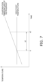
- the indoor control unit 92 continues the operation of the drain pump 59 for a predetermined period t2 from a time point t1 of transition from a state in which the evaporation temperature of the refrigerant is equal to or lower than the dew point temperature to a state in which the evaporation temperature of the refrigerant is higher than the dew point temperature. Thereafter, the indoor control unit 92 stops the operation of the drain pump 59 at a time point t3 when the predetermined period t2 has elapsed from the time point 11.
- the predetermined period t2 is, for example, one to five minutes.
- the indoor control unit 92 continues the operation of the drain pump 59 in a case of detecting an abnormality in at least one of the evaporation temperature thermistor 51, the indoor temperature sensor 52, and the indoor humidity sensor 53.
- the indoor control unit 92 detects the abnormality by receiving a signal related to occurrence of the abnormality from the evaporation temperature thermistor 51, the indoor temperature sensor 52, and the indoor humidity sensor 53.
- the indoor control unit 92 controls the drain pump 59 on the basis of at least one of the first determination criterion and the second determination criterion. In a case where both the first determination criterion and the second determination criterion are applied, the indoor control unit 92 continues the operation of the drain pump 59 even in a case where the operation of the drain pump 59 can be stopped on the basis of the first determination criterion. In other words, the second determination criterion is applied in preference to the first determination criterion.
- the indoor control unit 92 of the indoor unit 12 changes a method of controlling the drain pump 59 on the basis of the evaporation temperature of the refrigerant in the indoor heat exchanger 50 and the dew point temperature of the indoor air at the time of executing the cooling operation of the air conditioner 10. Specifically, in a case where the evaporation temperature of the refrigerant is higher than the dew point temperature and the speed at which the water level of the drain water in the drain pan 57 rises is low, the indoor control unit 92 continues the operation of the drain pump 59 or stops the operation of the drain pump 59 on the basis of the predetermined conditions. As a result, power consumption of the drain pump 59 is suppressed as compared with a case where the drain pump 59 is constantly operated.
- the indoor control unit 92 of the indoor unit 12 stops the operation of the drain pump 59 after the predetermined period has elapsed from the time point of transition from the state in which the evaporation temperature of the refrigerant is equal to or lower than the dew point temperature to the state in which the evaporation temperature of the refrigerant is higher than the dew point temperature.
- the speed at which the water level of the drain water in the drain pan 57 rises may be high as the drain water continues to accumulate in the drain pan 57. Therefore, in a case where the operation of drain pump 59 is stopped at the time point of transition to the state in which the evaporation temperature of the refrigerant is higher than the dew point temperature, the drain water may overflow the drain pan 57 and leak.
- the indoor control unit 92 of the indoor unit 12 continues the operation of the drain pump 59 in a case of detecting the abnormality in at least one of the evaporation temperature thermistor 51, the indoor temperature sensor 52, and the indoor humidity sensor 53.
- the indoor control unit 92 cannot normally acquire at least one of the evaporation temperature of the refrigerant and the dew point temperature.
- the indoor control unit 92 may erroneously determine that the evaporation temperature of the refrigerant is higher than the dew point temperature although the evaporation temperature of the refrigerant is actually equal to or lower than the dew point temperature. In a case where the indoor control unit 92 stops the operation of the drain pump 59 in this state, the drain water may overflow the drain pan 57 and leak.
- the indoor control unit 92 of the indoor unit 12 determines whether or not the dew condensation water is likely to be generated on the surface of the indoor heat exchanger 50 on the basis of the evaporation temperature of the refrigerant in the indoor heat exchanger 50 and the dew point temperature of the indoor air.
- the evaporation temperature of the refrigerant is detected by the evaporation temperature thermistor 51
- the dew point temperature of the indoor air is detected by the indoor temperature sensor 52 and the indoor humidity sensor 53.
- the evaporation temperature thermistor 51, the indoor temperature sensor 52, and the indoor humidity sensor 53 are sensors used in a conventional air conditioner 10 as well. Therefore, it is not necessary to use a special sensor for determining whether or not the dew condensation water is likely to be generated on the surface of the indoor heat exchanger 50, so that the cost of the indoor unit 12 is suppressed.
- the air conditioner 10 including the indoor unit 12 according to a second embodiment of the present disclosure has the same configuration and operation as those of the first embodiment.
- control of the indoor unit 12 at the time of executing the cooling operation which is a difference from the first embodiment, will be described.
- the indoor control unit 92 controls the drain pump 59 such that an operation start condition of the drain pump 59 in a first state and an operation start condition of the drain pump 59 in a second state are different from each other at the time of executing the cooling operation of the air conditioner 10.
- the operation start condition of the drain pump 59 is a condition related to the time to start the operation of the drain pump 59 after starting the air conditioner 10.
- the first state and the second state represent states of the air conditioner 10 after starting the air conditioner 10.
- the second state is a state in which a load on the air conditioner 10 at the time of executing the cooling operation is smaller than that in the first state.
- the first state is a state in which the evaporation temperature of the refrigerant in the indoor heat exchanger 50 is equal to or lower than the dew point temperature of the indoor air.
- the second state is a state in which the evaporation temperature of the refrigerant in the indoor heat exchanger 50 is higher than the dew point temperature of the indoor air. In a case where the evaporation temperature of the refrigerant is higher than the dew point temperature, water vapor contained in the indoor air is hardly condensed on a surface of the indoor heat exchanger 50.
- the second state is a state in which the amount of dew condensation water generated on the surface of the indoor heat exchanger 50 is smaller than that in the first state. Therefore, the second state is a state in which a speed at which the water level of the drain water in the drain pan 57 rises is lower than that in the first state.
- the definitions of the first state and the second state are not limited to the above definitions.
- the evaporation temperature of the refrigerant in the indoor heat exchanger 50 at the time of executing the cooling operation is detected by an evaporation temperature thermistor 51. As illustrated in FIG. 1 , the evaporation temperature thermistor 51 is attached to the indoor heat exchanger 50. The indoor control unit 92 acquires the evaporation temperature of the refrigerant in the indoor heat exchanger 50 from the evaporation temperature thermistor 51.
- the dew point temperature of the indoor air is calculated from data detected by an indoor temperature sensor 52 and an indoor humidity sensor 53. As illustrated in FIG. 1 , the indoor temperature sensor 52 and the indoor humidity sensor 53 are attached to the indoor unit 12. The indoor temperature sensor 52 and the indoor humidity sensor 53 are attached near the suction port 36 of the indoor unit 12.
- the indoor control unit 92 acquires a temperature of the indoor air sucked into the indoor unit 12 from the indoor temperature sensor 52.
- the indoor control unit 92 acquires relative humidity of the indoor air sucked into the indoor unit 12 from the indoor humidity sensor 53.
- the indoor control unit 92 calculates the dew point temperature of the indoor air from the temperature and the relative humidity of the indoor air.
- the indoor control unit 92 executes processing illustrated in FIG. 9 at predetermined time intervals.
- the indoor control unit 92 determines whether the state of the air conditioner 10 is the first state or the second state (step S31). For example, consider a case where the first state and the second state are defined as described above. In a case where the evaporation temperature of the refrigerant in the indoor heat exchanger 50 is higher than the dew point temperature of the indoor air, the indoor control unit 92 determines that the air conditioner 10 is in the second state. In a case where the evaporation temperature of the refrigerant in the indoor heat exchanger 50 is equal to or lower than the dew point temperature of the indoor air, the indoor control unit 92 determines that the air conditioner 10 is in the first state. Alternatively, the indoor control unit 92 may determine the state of the air conditioner 10 by another method.
- the indoor control unit 92 performs control of starting or continuing the operation of the drain pump 59 (step S32). Specifically, in a case of determining that the air conditioner 10 is in the first state in a state where the drain pump 59 is operating, the indoor control unit 92 continues the operation of the drain pump 59 without stopping the operation. Also, in a case of determining that the air conditioner 10 is in the first state in a state where the drain pump 59 is stopped, the indoor control unit 92 starts the operation of the drain pump 59. For example, in a case of determining that the air conditioner 10 is in the first state at the time of starting the air conditioner 10, the indoor control unit 92 immediately starts the operation of the drain pump 59.
- the indoor control unit 92 controls the operation of the drain pump 59 according to the change in the water level of the drain water in the drain pan 57.
- the indoor control unit 92 starts the operation of the drain pump 59 when the water level of the drain pan 57 rises to reach a first height h1, and stops the operation of the drain pump 59 when the water level of the drain pan 57 falls below the first height h1.
- the first height h1 is set to a position higher than a third height h3, which is a height position of the water suction port 59a of the drain pump 59, and lower than a second height h2.
- the second height h2 is a predetermined height position higher than the first height h1 and lower than the maximum water level h0.
- the water level of the drain pan 57 illustrated in FIG. 5 is the first height h1.
- the indoor control unit 92 does not start the operation of the drain pump 59.
- the indoor control unit 92 starts the operation of the drain pump 59.
- the indoor control unit 92 stops the operation of the drain pump 59.
- the indoor control unit 92 stops the compressor 20 while continuing the operation of the drain pump 59 in order to suppress the drain water from overflowing the drain pan 57 and leaking.
- the indoor control unit 92 transmits a control signal for stopping the compressor 20 to the outdoor control unit 91.
- the indoor control unit 92 may transmit a control signal for starting the operation of the compressor 20 to the outdoor control unit 91.
- the indoor control unit 92 acquires the water level of the drain pan 57 from the water level sensor 58 (step S33). Subsequently, the indoor control unit 92 determines whether or not the water level of the drain pan 57 is equal to or higher than the first height h1 (step S34). In a case where the water level of the drain pan 57 is equal to or higher than the first height h1, the indoor control unit 92 starts the operation of the drain pump 59 in a case where the operation of the drain pump 59 is stopped, and continues the operation of the drain pump 59 in a case where the drain pump 59 is operating (step S35).
- the indoor control unit 92 determines whether or not the water level of the drain pan 57 is equal to or higher than the second height h2 (step S36). In a case where the water level of the drain pan 57 is equal to or higher than the second height h2, the indoor control unit 92 stops the compressor 20 while continuing the operation of the drain pump 59 (step S37). In a case where the water level of the drain pan 57 is less than the second height h2, the indoor control unit 92 continues the operation of the drain pump 59 without stopping the compressor 20 (step S38).
- the indoor control unit 92 keeps the operation of the drain pump 59 stopped in a case where the operation of the drain pump 59 is stopped, and stops the operation of the drain pump 59 in a case where the drain pump 59 is operating (step S39).
- the indoor control unit 92 of the indoor unit 12 changes a method of controlling the drain pump 59 according to the load on the air conditioner 10 at the time of executing the cooling operation of the air conditioner 10. For example, in a case where the load on the air conditioner 10 is small and the speed at which the water level of the drain water in the drain pan 57 rises is low, the indoor control unit 92 does not start the operation of the drain pump 59 until the water level of the drain pan 57 reaches a predetermined height. As a result, power consumption of the drain pump 59 is suppressed as compared with a case where the drain pump 59 is constantly operated.
- the indoor control unit 92 of the indoor unit 12 stops the operation of the drain pump 59 when the water level of the drain pan 57 falls below the first height h1. As a result, power consumption of the drain pump 59 is suppressed as compared with a case where the drain pump 59 is constantly operated.
- the indoor control unit 92 of the indoor unit 12 starts the operation of the drain pump 59 when the water level of the drain pan 57 reaches the first height h1, which is higher than the third height h3, which is the height position of the water suction port 59a of the drain pump 59.
- the indoor control unit 92 does not start the operation of the drain pump 59 immediately after the water level of the drain pan 57 reaches the third height h3. In this manner, by setting the first height h1 so as to be higher than the third height h3 and delaying the time when the operation of the drain pump 59 starts, the power consumption of the drain pump 59 is suppressed.
- the indoor control unit 92 of the indoor unit 12 stops the operation of the drain pump 59.
- the indoor control unit 92 does not continue the operation of the drain pump 59 until the water level of the drain pan 57 is lowered to the third height h3, and stops the operation of the drain pump 59 at a time point when the water level is lowered to the first height h1, which is higher than the third height h3.
- the first height h1 is set so as to be higher than the third height h3, and the time to stop the operation of the drain pump 59 is advanced, whereby the power consumption of the drain pump 59 is suppressed.
- the indoor control unit 92 of the indoor unit 12 determines whether or not the dew condensation water is likely to be generated on the surface of the indoor heat exchanger 50 on the basis of the evaporation temperature of the refrigerant in the indoor heat exchanger 50 and the dew point temperature of the indoor air, and estimates the load on the air conditioner 10.
- the evaporation temperature of the refrigerant is detected by the evaporation temperature thermistor 51
- the dew point temperature of the indoor air is detected by the indoor temperature sensor 52 and the indoor humidity sensor 53.
- the evaporation temperature thermistor 51, the indoor temperature sensor 52, and the indoor humidity sensor 53 are sensors used in a conventional air conditioner 10 as well. Therefore, it is not necessary to use a special sensor for estimating the load on the air conditioner 10, so that the cost of the indoor unit 12 is suppressed.
- the air conditioner 10 including the indoor unit 12 according to a third embodiment of the present disclosure has the same configuration and operation as those of the second embodiment.
- control of the indoor unit 12 at the time of executing the cooling operation which is a difference from the second embodiment, will be described.
- the indoor control unit 92 changes the method of controlling the drain pump 59 according to the load of the air conditioner 10.
- the indoor control unit 92 controls the operation of the drain pump 59 according to the change in the water level of the drain water in the drain pan 57 regardless of a level of the load on the air conditioner 10.
- the indoor control unit 92 starts the operation of the drain pump 59 when the water level of the drain pan 57 rises to reach the first height h1, and stops the operation of the drain pump 59 when the water level of the drain pan 57 falls below the first height h1.
- the first height h1 is set to a position higher than the third height h3, which is a height position of the water suction port 59a of the drain pump 59, and lower than the second height h2.
- the indoor control unit 92 stops the compressor 20 while continuing the operation of the drain pump 59.
- the indoor control unit 92 starts the control from processing in step S33 without performing processing in steps S31 and S32 of FIG. 9 .
- the indoor control unit 92 of the indoor unit 12 starts the operation of the drain pump 59 when the water level of the drain pan 57 reaches the first height h1, which is higher than the third height h3, which is the height position of the water suction port 59a of the drain pump 59.
- the indoor control unit 92 does not start the operation of the drain pump 59 immediately after the water level of the drain pan 57 reaches the third height h3.
- the power consumption of the drain pump 59 is suppressed.
- the indoor control unit 92 of the indoor unit 12 stops the operation of the drain pump 59.
- the indoor control unit 92 does not continue the operation of the drain pump 59 until the water level of the drain pan 57 is lowered to the third height h3, and stops the operation of the drain pump 59 at a time point when the water level is lowered to the first height h1, which is higher than the third height h3.
- the first height h1 is set so as to be higher than the third height h3, and the time to stop the operation of the drain pump 59 is advanced, whereby the power consumption of the drain pump 59 is suppressed.
- the indoor control unit 92 determines that the second condition is satisfied in a case where the evaporation temperature of the refrigerant in the indoor heat exchanger 50 is higher than the dew point temperature of the indoor air.
- the indoor control unit 92 may determine that the second condition is satisfied in a case where a difference between the evaporation temperature of the refrigerant and the dew point temperature of the indoor air is smaller than a predetermined value when the evaporation temperature of the refrigerant is equal to or lower than the dew point temperature of the indoor air. In other words, for example, the indoor control unit 92 may determine that the second condition is satisfied even in a case where the evaporation temperature of the refrigerant is slightly lower than the dew point temperature of the indoor air.
- the indoor control unit 92 determines that the second condition is satisfied in a case where an evaporation temperature Tc of the refrigerant and a dew point temperature Td of the indoor air satisfy a relational expression Td - c ⁇ Tc.
- a constant c is the predetermined value described above, and is, for example, 1°C or 2°C.
- the amount of dew condensation water generated on the surface of the indoor heat exchanger 50 may be small as in a case where the evaporation temperature of the refrigerant is higher than the dew point temperature of the indoor air.
- the indoor unit 12 by controlling the indoor unit 12 by defining the second condition as described above, the operation time of the drain pump 59 is shortened, so that the power consumption of the drain pump 59 is suppressed.
- the indoor control unit 92 may continue the operation of the drain pump 59 for a predetermined period from a time point of transition from a state in which the evaporation temperature Tc of the refrigerant is equal to or lower than a temperature Td-c slightly lower than the dew point temperature of the indoor air to a state in which the evaporation temperature Tc of the refrigerant is higher than the temperature Td-c. Thereafter, the indoor control unit 92 stops the operation of the drain pump 59at a time point when the predetermined period has elapsed.
- the indoor control unit 92 of the first embodiment may determine whether or not to perform the first control depending on the load on the air conditioner at the time of executing the cooling operation. For example, the indoor control unit 92 may start or continue the operation of the drain pump without performing the first control in the first state, and perform the first control in the second state.
- the first state and the second state represent states of the air conditioner 10 after starting the air conditioner 10.
- the second state is a state in which a load on the air conditioner 10 at the time of executing the cooling operation is smaller than that in the first state.
- the indoor control unit 92 continues the operation of the drain pump 59 when the air conditioner 10 is in the first state.
- the indoor control unit 92 performs the first control of the first embodiment when the air conditioner 10 is in the second state.
- the indoor control unit 92 executes processing illustrated in FIG. 8 at predetermined time intervals.
- the indoor control unit 92 determines whether the state of the air conditioner 10 is the first state or the second state (step S21). The indoor control unit 92 determines the state of the air conditioner 10 on the basis of parameters such as the numbers of rotations of the compressor 20, the outdoor fan 35, and the indoor fan 55 and the difference between the temperature of the indoor air and the temperature of the outdoor air.
- the indoor control unit 92 performs control of starting or continuing the operation of the drain pump 59 (step S22). Specifically, in a case of determining that the air conditioner 10 is in the first state in a state where the drain pump 59 is operating, the indoor control unit 92 continues the operation of the drain pump 59 without stopping the operation. Also, in a case of determining that the air conditioner 10 is in the first state in a state where the drain pump 59 is stopped, the indoor control unit 92 starts the operation of the drain pump 59. For example, in a case of determining that the air conditioner 10 is in the first state at the time of starting the air conditioner 10, the indoor control unit 92 immediately starts the operation of the drain pump 59.
- the indoor control unit 92 performs the same processing as steps S11 to S14 of the first embodiment (steps S23 to S26) as described below.
- the indoor control unit 92 acquires the evaporation temperature of the refrigerant in the indoor heat exchanger 50 and the dew point temperature of the indoor air (step S23).
- the indoor control unit 92 acquires a detection value of the evaporation temperature of the refrigerant from the evaporation temperature thermistor 51.
- the indoor control unit 92 acquires detection values of the temperature and the relative humidity of the indoor air from the indoor temperature sensor 52 and the indoor humidity sensor 53, and calculates the dew point temperature of the indoor air.
- the indoor control unit 92 determines whether or not the evaporation temperature of the refrigerant is equal to or lower than the dew point temperature of the indoor air (step S24). In a case of determining that the evaporation temperature of the refrigerant is equal to or lower than the dew point temperature of the indoor air, the indoor control unit 92 performs control of starting or continuing the operation of the drain pump 59 (step S25). Specifically, in a case where the drain pump 59 is operating, the indoor control unit 92 continues the operation of the drain pump 59 without stopping the operation. In a case where the drain pump 59 is stopped, the indoor control unit 92 starts the operation of the drain pump 59. For example, the indoor control unit 92 immediately starts the operation of the drain pump 59 in a case of determining that the evaporation temperature of the refrigerant is equal to or lower than the dew point temperature of the indoor air at the time of starting the air conditioner 10.
- the indoor control unit 92 controls the drain pump 59 so that the drain pump 59 has a period of not operating (step S26).
- the indoor control unit 92 of the indoor unit 12 constantly operates the drain pump 59 in a case where the load on the air conditioner 10 is large at the time of executing the cooling operation of the air conditioner 10.
- the speed at which the water level of the drain water in the drain pan 57 rises is high. Therefore, leakage of the drain water due to the rapid rise in the water level of the drain pan 57 is suppressed.
- the indoor control unit 92 of the indoor unit 12 changes the method of controlling the drain pump 59 on the basis of the evaporation temperature of the refrigerant in the indoor heat exchanger 50 and the dew point temperature of the indoor air.
- the indoor control unit 92 continues the operation of the drain pump 59 or stops the operation of the drain pump 59 based on the predetermined conditions. As a result, power consumption of the drain pump 59 is suppressed as compared with a case where the drain pump 59 is constantly operated.
- the indoor unit 12 according to the first embodiment is used in the air conditioner 10 having cooling and heating functions.
- the indoor unit 12 may be used in the air conditioner 10 dedicated to cooling.
- the second state is defined as a state in which the evaporation temperature of the refrigerant in the indoor heat exchanger 50 is higher than the dew point temperature of the indoor air.
- the indoor control unit 92 determines that the air conditioner 10 is in the second state.
- a state in which the difference between the evaporation temperature of the refrigerant and the dew point temperature of the indoor air is smaller than the predetermined value may also be defined to fall within the second state.
- a state in which the evaporation temperature of the refrigerant is slightly lower than the dew point temperature of the indoor air may also be defined as the second state.
- the indoor control unit 92 determines that the air conditioner 10 is in the second state in a case where the evaporation temperature Tc of the refrigerant and the dew point temperature Td of the indoor air satisfy the relational expression Td - c ⁇ Tc.
- a constant c is the predetermined value described above, and is, for example, 1°C or 2°C.
- the amount of dew condensation water generated on the surface of the indoor heat exchanger 50 may be small as in a case where the evaporation temperature of the refrigerant is higher than the dew point temperature of the indoor air.
- the operation time of the drain pump 59 is shortened, so that the power consumption of the drain pump 59 is suppressed.
- the first height h1 is set to the position higher than the height h3 of the water suction port 59a of the drain pump 59 and lower than the second height h2.
- the first height h1 may further be set to a position lower than an intermediate height position (h2 + h3)/2 between the height h3 of the water suction port 59a of the drain pump 59 and the second height h2.
- the water level of the drain pan 57 which is a condition for starting the operation of the drain pump 59, is set near the water suction port 59a of the drain pump 59. As a result, leakage of the drain water due to a rapid rise in the water level of the drain pan 57 is suppressed.
- the indoor unit 12 is used in the air conditioner 10 having cooling and heating functions.
- the indoor unit 12 may be used in the air conditioner 10 dedicated to cooling.
- Patent Literature 1 JP H07-332743 A
Landscapes
- Engineering & Computer Science (AREA)
- Chemical & Material Sciences (AREA)
- Combustion & Propulsion (AREA)
- Mechanical Engineering (AREA)
- General Engineering & Computer Science (AREA)
- Air Conditioning Control Device (AREA)
- Devices For Blowing Cold Air, Devices For Blowing Warm Air, And Means For Preventing Water Condensation In Air Conditioning Units (AREA)
Abstract
Description
- The present disclosure relates to an indoor unit, and an air conditioner.
- An air conditioner disclosed in Patent Literature 1 (
JP H07-332743 A - In a case where the amount of drain water generated is large, lack of continuous operation of the drain pump may cause the water level of the drain water in the drain pan to rise rapidly and cause the drain water to overflow the drain pan. However, in a case where the amount of the drain water generated is small, it is preferable to suppress power consumption of the drain pump by shortening operation time of the drain pump.
- An indoor unit according to a first aspect is used in an air conditioner capable of executing a cooling operation by circulating a refrigerant. The indoor unit includes a heat exchanger, a drain pan, a drain pump, and a control unit. The heat exchanger exchanges heat between the refrigerant and indoor air. The drain pan receives water generated in the heat exchanger. The drain pump sucks up the water from the drain pan. The control unit performs a first control at a time of executing the cooling operation. In the first control, the control unit operates the drain pump when an evaporation temperature of the refrigerant in the heat exchanger is equal to or lower than a dew point temperature of the indoor air. In the first control, the control unit controls the drain pump so as to have a period in which operation of the drain pump is not performed when the evaporation temperature is higher than the dew point temperature.
- The indoor unit according to the first aspect controls the drain pump so as to have the period in which operation of the drain pump is not performed in a case where the amount of the water generated in the heat exchanger is small. Accordingly, power consumption of the drain pump is suppressed.
- An indoor unit according to a second aspect is the indoor unit according to the first aspect, wherein, in a first control, the control unit continues the operation of the drain pump for a predetermined period from a time point of transition from a state in which the evaporation temperature is equal to or lower than the dew point temperature to a state in which the evaporation temperature is higher than the dew point temperature, and thereafter stops the operation of the drain pump.
- In the indoor unit according to the second aspect, leakage of the water due to a rise in a water level of the drain pan is suppressed.
- An indoor unit according to a third aspect is the indoor unit according to the first or second aspect, wherein, at the time of executing the cooling operation, the control unit continues the operation of the drain pump in a case of detecting an abnormality in a first sensor for acquiring the evaporation temperature or a second sensor for acquiring the dew point temperature.
- In the indoor unit according to the third aspect, leakage of the water due to the rise in the water level of the drain pan is suppressed.
- An indoor unit according to a fourth aspect is the indoor unit according to any one of the first to third aspects, wherein, at the time of executing the cooling operation, the control unit continues the operation of the drain pump in a first state. The control unit performs, at the time of executing the cooling operation, the first control in a second state, in which a load on the air conditioner at the time of executing the cooling operation is smaller than that in the first state.
- The indoor unit according to the fourth aspect constantly operates the drain pump in a case where the load on the air conditioner is large and the amount of the water generated in the heat exchanger is large. On the other hand, the indoor unit controls the drain pump so as to have the period in which operation of the drain pump is not performed in a case where the load on the air conditioner is small and the amount of the water generated in the heat exchanger is small. As a result, leakage of the water due to a rapid rise in the water level of the drain pan is suppressed, and the power consumption of the drain pump is suppressed.
- An air conditioner according to a fifth aspect includes the indoor unit according to any one of the first to fourth aspects.
- In the air conditioner according to the fifth aspect, since the power consumption of the drain pump is suppressed, power necessary for the operation is suppressed.
- An indoor unit according to a sixth aspect is used in an air conditioner capable of executing a cooling operation by circulating a refrigerant. The indoor unit includes a heat exchanger, a drain pan, a drain pump, and a control unit. The heat exchanger exchanges heat between the refrigerant and indoor air. The drain pan receives water generated in the heat exchanger. The drain pump sucks up the water from the drain pan. At a time of executing the cooling operation, the control unit controls the drain pump such that an operation start condition of the drain pump in a first state and an operation start condition of the drain pump in a second state are different from each other. The second state is a state in which a load on the air conditioner at the time of executing the cooling operation is smaller than that in the first state.
- The indoor unit according to the sixth aspect changes the operation start condition of the drain pump according to the load on the air conditioner at the time of executing the cooling operation. For example, in a case where the load on the air conditioner is small and the amount of the water generated in the heat exchanger is small, the indoor unit does not start operation of the drain pump until a water level of the drain pan reaches a predetermined height. Accordingly, power consumption of the drain pump is suppressed.
- An indoor unit according to a seventh aspect is the indoor unit according to the sixth aspect, wherein, at the time of executing the cooling operation, the control unit continues operation of the drain pump in the first state. At the time of executing the cooling operation, in the second state, the control unit starts the operation of the drain pump when a water level of the drain pan rises to reach a predetermined height, and stops the operation of the drain pump when the water level of the drain pan falls below the predetermined height.
- The indoor unit according to the seventh aspect constantly operates the drain pump in a case where the load on the air conditioner is large and the amount of the water generated in the heat exchanger is large. On the other hand, in a case where the load on the air conditioner is small and the amount of the water generated in the heat exchanger is small, the indoor unit stops the operation of the drain pump when the water level of the drain pan falls below the predetermined height. As a result, leakage of the water due to a rapid rise in the water level of the drain pan is suppressed, and the power consumption of the drain pump is suppressed.
- An indoor unit according to an eighth aspect is the indoor unit according to the seventh aspect, wherein the predetermined height is higher than a height of a water suction port of the drain pump.
- The indoor unit according to the eighth aspect starts the operation of the drain pump after the water level of the drain pan exceeds the height of the water suction port of the drain pump in a case where the amount of the water generated in the heat exchanger is small. Accordingly, power consumption of the drain pump is suppressed.
- An indoor unit according to a ninth aspect is the indoor unit according to any one of the sixth to eighth aspects, wherein the second state includes a state in which an evaporation temperature of the refrigerant in the heat exchanger is higher than a dew point temperature of the indoor air, or a state in which a difference between the evaporation temperature and the dew point temperature is smaller than a predetermined value in a case where the evaporation temperature is equal to or lower than the dew point temperature.
- The indoor unit according to the ninth aspect determines the amount of the water generated in the heat exchanger from the evaporation temperature of the refrigerant in the heat exchanger and the dew point temperature of the indoor air. Since the evaporation temperature and the dew point temperature can be measured using a conventional sensor, cost is suppressed.
- An air conditioner according to a tenth aspect includes the indoor unit according to any one of the sixth to ninth aspects.
- In the air conditioner according to the tenth aspect, since the power consumption of the drain pump is suppressed, power necessary for the operation is suppressed.
- An indoor unit according to an eleventh aspect is used in an air conditioner capable of executing a cooling operation by circulating a refrigerant. The indoor unit includes a heat exchanger, a drain pan, a drain pump, and a control unit. The heat exchanger exchanges heat between the refrigerant and indoor air. The drain pan receives water generated in the heat exchanger. The drain pump sucks up the water from the drain pan. The control unit performs a first control at a time of executing the cooling operation. In the first control, when a water level of the drain pan rises to reach a first height, the control unit starts operation of the drain pump. In the first control, when the water level of the drain pan rises to reach a second height, which is higher than the first height, the control unit stops a compressor of the air conditioner while continuing the operation of the drain pump. In the first control, when the water level of the drain pan falls below the first height, the control unit stops the operation of the drain pump. The first height is higher than a height of a water suction port of the drain pump.
- At the time of executing the cooling operation, the indoor unit according to the eleventh aspect starts the operation of the drain pump when the water level of the drain pan reaches a predetermined height, and stops the operation of the drain pump when the water level of the drain pan falls below the predetermined height. Accordingly, power consumption of the drain pump is suppressed.
- An indoor unit according to a twelfth aspect is the indoor unit according to the eleventh aspect, wherein, at the time of executing the cooling operation, the control unit continues the operation of the drain pump in a first state. The control unit performs, at the time of executing the cooling operation, the first control in a second state, in which a load on the air conditioner at the time of executing the cooling operation is smaller than that in the first state.
- The indoor unit according to the twelfth aspect constantly operates the drain pump in a case where the load on the air conditioner is large and the amount of the water generated in the heat exchanger is large. On the other hand, in a case where the load on the air conditioner is small and the amount of the water generated in the heat exchanger is small, the indoor unit stops the operation of the drain pump when the water level of the drain pan falls below the predetermined height. As a result, leakage of the water due to a rapid rise in the water level of the drain pan is suppressed, and the power consumption of the drain pump is suppressed.
- An indoor unit according to a thirteenth aspect is the indoor unit according to the twelfth aspect, wherein the second state includes a state in which an evaporation temperature of the refrigerant in the heat exchanger is higher than a dew point temperature of the indoor air, or a state in which a difference between the evaporation temperature and the dew point temperature is smaller than a predetermined value in a case where the evaporation temperature is equal to or lower than the dew point temperature.
- The indoor unit according to the thirteenth aspect determines the amount of the water generated in the heat exchanger from the evaporation temperature of the refrigerant in the heat exchanger and the dew point temperature of the indoor air. Since the evaporation temperature and the dew point temperature can be measured using a conventional sensor, cost is suppressed.
- An indoor unit according to a fourteenth aspect is the indoor unit according to any one of the eleventh to thirteenth aspects, wherein the first height is equal to or less than an intermediate height between the height of the water suction port and the second height.
- In the indoor unit according to the fourteenth aspect, the water level of the drain pan, which is a condition for starting the operation of the drain pump, is set near the water suction port of the drain pump. As a result, leakage of the water due to a rapid rise in the water level of the drain pan is suppressed.
- An air conditioner according to a fifteenth aspect includes the indoor unit according to any one of the eleventh to fourteenth aspects.
- In the air conditioner according to the fifteenth aspect, since the power consumption of the drain pump is suppressed, power necessary for the operation is suppressed.
-
-
FIG. 1 is a diagram illustrating a refrigerant circuit of anair conditioner 10 including anindoor unit 12. -
FIG. 2 is a schematic view of theindoor unit 12 installed in aceiling space 80. -
FIG. 3 is a perspective view of theindoor unit 12. -
FIG. 4 is a cross-sectional view of theindoor unit 12. -
FIG. 5 is a schematic configuration diagram of adrain pan 57 and adrain pump 59. -
FIG. 6 is a flowchart illustrating control of thedrain pump 59 according to a first embodiment. -
FIG. 7 is a time chart for explaining a first determination criterion in step S14 ofFIG. 6 . -
FIG. 8 is a flowchart illustrating control of thedrain pump 59 according to Modification Example B. -
FIG. 9 is a flowchart illustrating control of thedrain pump 59 according to a second embodiment. - An
air conditioner 10 that includes anindoor unit 12 according to a first embodiment of the present disclosure will be described with reference to the drawings. - As illustrated in
FIG. 1 , theair conditioner 10 is a refrigerant pipe-scheme air conditioner, and heats and cools each room in a building by executing a vapor compression refrigeration cycle operation. Theair conditioner 10 includes anoutdoor unit 11, anindoor unit 12, a liquid-refrigerant connection pipe 13, and a gas-refrigerant connection pipe 14. Theoutdoor unit 11 and theindoor unit 12 are connected via the liquid-refrigerant connection pipe 13 and the gas-refrigerant connection pipe 14. This configures a refrigerant circuit of theair conditioner 10. In the refrigerant circuit of theair conditioner 10, a refrigerant sealed in the refrigerant circuit circulates. Theair conditioner 10 performs a refrigeration cycle operation in which the refrigerant is compressed, radiates heat (condensed), decompressed, absorbs heat (evaporated), and then compressed again in the refrigerant circuit. - The
outdoor unit 11 is disposed outside the building, in a basement of the building, or the like. Theoutdoor unit 11 mainly includes acompressor 20, a four-way switching valve 15, anoutdoor heat exchanger 30, anoutdoor expansion valve 41, anoutdoor fan 35, a liquid-side shutoff valve 17, a gas-side shutoff valve 18, anaccumulator 25, and anoutdoor control unit 91. - As illustrated in
FIG. 2 , theindoor unit 12 is installed in aceiling space 80 located above aceiling 81 of each room. Theindoor unit 12 is an indoor unit of a type to be installed by being built in theceiling 81. Theindoor unit 12 mainly includes acasing 22, a winddirection changing member 39, anindoor heat exchanger 50, anindoor fan 55, abell mouth 56, adrain pan 57, adrain pump 59, and anindoor control unit 92. Theair conditioner 10 has a decentralized configuration in which the plurality ofindoor units 12 are connected to oneoutdoor unit 11. However, for example, theair conditioner 10 may have a configuration in which oneindoor unit 12 is connected to oneoutdoor unit 11. - One end of the
indoor heat exchanger 50 is connected to the liquid-refrigerant connection pipe 13, and the other end thereof is connected to the gas-refrigerant connection pipe 14. Theindoor heat exchanger 50 functions as a heat absorber (evaporator) or a radiator (condenser) for the refrigerant. When theair conditioner 10 is performing a cooling operation, theindoor heat exchanger 50 functions as the heat absorber. When theair conditioner 10 is performing a heating operation, theindoor heat exchanger 50 functions as the radiator. - The
outdoor control unit 91 is a computer that controls components of theoutdoor unit 11. Theindoor control unit 92 is a computer that controls components of theindoor unit 12. Each of theoutdoor control unit 91 and theindoor control unit 92 mainly includes an arithmetic device and a storage device. The arithmetic device is, for example, a CPU or a GPU. The arithmetic device reads a program stored in the storage device and performs predetermined arithmetic processing in accordance with the program. The arithmetic device writes a result of the arithmetic processing in the storage device and reads information stored in the storage device in accordance with the program. Theoutdoor control unit 91 is connected to theindoor control unit 92 via a communication line to transmit and receive data, a control signal, and the like. - The liquid-
refrigerant connection pipe 13 and the gas-refrigerant connection pipe 14 are refrigerant pipes laid on site when theoutdoor unit 11 and theindoor unit 12 are installed in the building. As illustrated inFIG. 2 , the liquid-refrigerant connection pipe 13 and the gas-refrigerant connection pipe 14 pass through theceiling space 80. - Inside the
casing 22 are mainly provided theindoor heat exchanger 50, theindoor fan 55, thebell mouth 56, thedrain pan 57, thedrain pump 59, and theindoor control unit 92. Thecasing 22 mainly includes a casingmain body 22a and aface panel 22b. - As illustrated in
FIG. 2 , the casingmain body 22a is disposed so as to be inserted into anopening 81a formed in theceiling 81 of each room. The casingmain body 22a is a substantially octagonal box-shaped body in which long sides and short sides are alternately formed in a planar view, and a lower surface thereof is opened. The casingmain body 22a has a top panel, and a plurality of side plates extending downward from a peripheral edge of the top panel. - The
face panel 22b is disposed so as to be fitted into theopening 81a of theceiling 81. Theface panel 22b extends further to an outside than the top panel and the side plates of the casingmain body 22a in the planar view, and is attached to a lower part of the casingmain body 22a from an indoor side. - As illustrated in
FIG. 3 , theface panel 22b includes aninner frame 23a and anouter frame 23b provided outside theinner frame 23a in the planar view. Inside theinner frame 23a in the planar view is formed asuction port 36 having a substantially quadrangular shape in the planar view opened downward. Inside theouter frame 23b and outside theinner frame 23a in the planar view are formed a blow-out port 37 opened in a range from a downward direction to a diagonally downward direction and a corner blow-outport 38. As illustrated inFIG. 4 , afilter 34 is provided above thesuction port 36 to remove dust from air sucked through thesuction port 36. The blow-out port 37 includes a first blow-outport 37a, a second blow-outport 37b, a third blow-outport 37c, and a fourth blow-outport 37d. These blow-out ports are provided between theinner frame 23a and theouter frame 23b so as to extend in parallel with respective sides of thesuction port 36 having a substantially quadrangular shape in the planar view. The corner blow-outport 38 includes a first corner blow-outport 38a, a second corner blow-outport 38b, a third corner blow-outport 38c, and a fourth corner blow-outport 38d. These corner blow-out ports are provided at four corners of a place between theinner frame 23a and theouter frame 23b in the planar view. - The wind
direction changing member 39 is attached to a lower surface of the casingmain body 22a. The winddirection changing member 39 is a member that can change a direction of air flow passing through the blow-out port 37. The winddirection changing member 39 includes a first winddirection changing member 39a disposed at the first blow-outport 37a, a second winddirection changing member 39b disposed at the second blow-outport 37b, a third winddirection changing member 39c disposed at the third blow-outport 37c, and a fourth winddirection changing member 39d disposed at the fourth blow-outport 37d. Each of the winddirection changing members 39a to 39d includes a flap main body and an arm Z. The flap main body is a plate-shaped member having a concave surface X having a concave cross-sectional shape perpendicular to a rotational axis, and a convex surface Y on a back side of the concave surface X and having a convex cross-sectional shape perpendicular to the rotational axis. The concave surface X is a surface facing an upstream side of the blow-out port 37 when theair conditioner 10 is stopped, and includes a plurality of knurls extending in a longitudinal direction. The convex surface Y is a surface facing to a lower side, which is an indoor space side, at a time of stopping, and has a smooth face surface. The arm Z is secured to a side of the flap main body provided with the concave surface X. An end of the arm Z opposite to the flap main body is pivotally supported so as to be rotatable via a drive shaft with respect to a structural component extending from an interior of the indoor unit 3. Each of the drive shafts extends along the longitudinal direction of each of the blow-outports 37a to 37d in the planar view. The winddirection changing member 39 includes a not-illustrated stepping motor connected to an end of the corresponding drive shaft. The flap main body and the arm Z receive a driving force from the motor to rotate via the drive shaft, thereby changing a wind direction. A posture of the winddirection changing member 39 is controlled so that the winddirection changing member 39 may have a plurality of kinds of predetermined angles determined in advance according to a degree of rotation of the drive shaft. During the cooling operation and the heating operation, air passing through the upstream side of the blow-out port 37 mainly hits the concave surface X of the flap main body. - The respective postures of the first wind
direction changing member 39a, the second winddirection changing member 39b, the third winddirection changing member 39c, and the fourth winddirection changing member 39d are independently controlled by theindoor control unit 92. When receiving a wind direction instruction from a user via a remote control or the like, theindoor control unit 92 drives the drive shaft to cause the posture of the winddirection changing member 39 to be controlled. - The
indoor heat exchanger 50 is a heat exchanger that is disposed inside the casingmain body 22a in a bent state so as to surround theindoor fan 55 in the planar view. More specifically, theindoor heat exchanger 50 includes multiple heat transfer fins arranged at predetermined spaces, and a plurality of heat transfer tubes penetrating the heat transfer fins in a thickness direction. A liquid side of theindoor heat exchanger 50 is connected to an end of the liquid-refrigerant connection pipe 13, and a gas side of theindoor heat exchanger 50 is connected to an end of the gas-refrigerant connection pipe 14. - The
indoor fan 55 is a centrifugal fan arranged inside the casingmain body 22a. Theindoor fan 55 forms an air flow where indoor air is sucked into thecasing 22 through thesuction port 36 of theface panel 22b, passes through theindoor heat exchanger 50, and is then blown out of thecasing 22 through the blow-out port 37 of theface panel 22b. Theindoor fan 55 includes afan motor 55a provided at a center of the top panel of the casingmain body 22a and an impeller connected to thefan motor 55a and rotationally driven. The impeller is an impeller having a turbo blade, and can suck air into the impeller from below and blow out the air toward an outer peripheral side of the impeller in the planar view by rotating about a rotational axis O. The number of rotations of theindoor fan 55 is controlled by theindoor control unit 92 to enable air volume to be controlled in a plurality of levels. - As illustrated in
FIG. 4 , thedrain pan 57 is disposed below theindoor heat exchanger 50, and receives drain water generated by condensation of moisture contained in air at theindoor heat exchanger 50. Thedrain pan 57 is attached to a lower portion of the casingmain body 22a. Thedrain pan 57 is provided with a cylindrical space extending in an up-down direction inside theindoor heat exchanger 50 in the planar view. On a lower side inside the space, thebell mouth 56 is disposed. Thebell mouth 56 is a member for guiding air sucked from thesuction port 36 to theindoor fan 55, and has a flat portion extending horizontally and a cylindrical portion extending in the up-down direction around a center. - The
drain pan 57 includes a plurality of blow-outchannels 47 extending in the up-down direction outside theindoor heat exchanger 50 in the planar view. The blow-outchannels 47 have a first blow-out channel communicating with the first blow-outport 37a at a lower end of the first blow-out channel, a second blow-out channel communicating with the second blow-outport 37b at a lower end of the second blow-out channel, a third blow-out channel communicating with the third blow-outport 37c at a lower end of the third blow-out channel, and a fourth blow-out channel communicating with the fourth blow-outport 37d at a lower end of the fourth blow-out channel. Also, the blow-outchannels 47 have a first corner blow-out channel communicating with the first corner blow-outport 38a at a lower end of the first corner blow-out channel, a second corner blow-out channel communicating with the second corner blow-outport 38b at a lower end of the second corner blow-out channel, a third corner blow-out channel communicating with the third corner blow-outport 38c at a lower end of the third corner blow-out channel, and a fourth corner blow-out channel communicating with the fourth corner blow-outport 38d at a lower end of the fourth corner blow-out channel. - When the
air conditioner 10 is performing the cooling operation, dew condensation water may be generated on a surface of theindoor heat exchanger 50. Thedrain pan 57 is provided to receive the dew condensation water falling from the surface of theindoor heat exchanger 50. The dew condensation water falling from the surface of theindoor heat exchanger 50 is stored in thedrain pan 57 as drain water. - As illustrated in
FIG. 5 , thedrain pan 57 has aconcave portion 57a that is a space in which the drain water is stored. A bottom surface of theconcave portion 57a is disposed so as to be substantially parallel to a horizontal plane. Therefore, a water surface of the drain water in thedrain pan 57 is substantially parallel to the horizontal plane. Hereinbelow, a water level means a vertical height position of the water surface of the drain water in thedrain pan 57 with reference to the bottom surface of theconcave portion 57a. When no drain water is stored in thedrain pan 57, the water level is 0. The water level when the drain water is stored in thedrain pan 57 up to a height position of anupper end 57b of thedrain pan 57 is a maximum water level h0. When the drain water falls from theindoor heat exchanger 50 into thedrain pan 57 with the water level being the maximum water level h0, the drain water leaks from thedrain pan 57. - A
water level sensor 58 is disposed in thedrain pan 57. Thewater level sensor 58 mainly includes afloat 58a and asupport 58b. Thefloat 58a is a member that can float on the drain water. Thefloat 58a rises or drops according to a change in the water level of thedrain pan 57. Thesupport 58b supports thefloat 58a. Theindoor control unit 92 acquires the water level of thedrain pan 57 by detecting a height position of thefloat 58a. - The
drain pump 59 discharges the drain water from thedrain pan 57. Thedrain pump 59 has awater suction port 59a and awater drain port 59b. Thedrain pump 59 sucks the drain water in thedrain pan 57 from thewater suction port 59a and discharges the same from thewater drain port 59b. - The
water suction port 59a is located at a tip end of a portion protruding downward from an upper side of thedrain pump 59. Thewater suction port 59a is located in theconcave portion 57a of thedrain pan 57. Thewater suction port 59a is located above the bottom surface of theconcave portion 57a of thedrain pan 57 and below theupper end 57b of thedrain pan 57. - The
water drain port 59b is a tip opening of a copper pipe protruding from a side plate of thecasing 22. As illustrated inFIGS. 2 and5 , adrain pipe 60 is connected to thewater drain port 59b. Thedrain pipe 60 is installed in theceiling space 80. Thedrain pipe 60 is a pipe for draining the drain water into an outside of the building or a drain ditch of the building. - The
drain pump 59 applies pressure to the drain water in thedrain pan 57 by driving of a not-illustrated motor, sucks up the drain water from thedrain pan 57, and sends the drain water to thedrain pipe 60. Accordingly, thedrain pump 59 discharges the drain water to the outside of theindoor unit 12. Theindoor control unit 92 controls time to start operation of thedrain pump 59 and time to stop operation of thedrain pump 59. - In a case where the
air conditioner 10 executes the heating operation, the four-way switching valve 15 is switched to a state illustrated by a broken line inFIG. 1 . In the refrigerant circuit of theair conditioner 10, a low-pressure gas refrigerant of the refrigeration cycle is sucked into thecompressor 20, and discharged after compressed to a high-pressure refrigerant of the refrigeration cycle. The high-pressure gas refrigerant discharged from thecompressor 20 is sent to theindoor heat exchanger 50 via the four-way switching valve 15, the gas-side shutoff valve 18, and the gas-refrigerant connection pipe 14. The high-pressure gas refrigerant sent to theindoor heat exchanger 50 is condensed by heat exchange with indoor air in theindoor heat exchanger 50, and becomes a high-pressure liquid refrigerant. The indoor air is thus heated. The liquid refrigerant that has been condensed in theindoor heat exchanger 50 is sent to theoutdoor expansion valve 41 through the liquid-refrigerant connection pipe 13 and the liquid-side shutoff valve 17. The refrigerant sent to theoutdoor expansion valve 41 is decompressed by theoutdoor expansion valve 41 to low pressure in the refrigeration cycle. The low-pressure refrigerant decompressed in theoutdoor expansion valve 41 is sent to theoutdoor heat exchanger 30. The low-pressure refrigerant sent to theoutdoor heat exchanger 30 is evaporated by heat exchange with outdoor air in theoutdoor heat exchanger 30, and becomes a low-pressure gas refrigerant. The low-pressure refrigerant that has been evaporated in theoutdoor heat exchanger 30 is sucked again into thecompressor 20 via the four-way switching valve 15 and theaccumulator 25. - In a case where the
air conditioner 10 executes the cooling operation, the four-way switching valve 15 is switched to a state illustrated by a solid line inFIG. 1 . In the refrigerant circuit of theair conditioner 10, a low-pressure gas refrigerant of the refrigeration cycle is sucked into thecompressor 20, and discharged after compressed to a high-pressure refrigerant of the refrigeration cycle. The high-pressure gas refrigerant discharged from thecompressor 20 is sent to theoutdoor heat exchanger 30 through the four-way switching valve 15. The high-pressure gas refrigerant sent to theoutdoor heat exchanger 30 is condensed by heat exchange with outdoor air in theoutdoor heat exchanger 30, and becomes a high-pressure liquid refrigerant. The liquid refrigerant that has been condensed in theoutdoor heat exchanger 30 is decompressed by theoutdoor expansion valve 41 to low pressure in the refrigeration cycle. The low-pressure refrigerant decompressed in theoutdoor expansion valve 41 is sent to theindoor heat exchanger 50 through the liquid-side shutoff valve 17 and the liquid-refrigerant connection pipe 13. The refrigerant sent to theindoor heat exchanger 50 is evaporated by heat exchange with indoor air in theindoor heat exchanger 50, and becomes a low-pressure gas refrigerant. The indoor air is thus cooled. The gas refrigerant that has been evaporated in theindoor heat exchanger 50 is sucked again into thecompressor 20 via the gas-refrigerant connection pipe 14, the gas-side shutoff valve 18, the four-way switching valve 15, and theaccumulator 25. - The
indoor control unit 92 performs a first control at a time of executing the cooling operation of theair conditioner 10. In the first control, theindoor control unit 92 operates thedrain pump 59 when the first condition that an evaporation temperature of the refrigerant in theindoor heat exchanger 50 is equal to or lower than a dew point temperature of the indoor air is satisfied. In the first control, theindoor control unit 92 controls thedrain pump 59 so as to have a period in which operation of thedrain pump 59 is not performed when a second condition that the evaporation temperature of the refrigerant in theindoor heat exchanger 50 is higher than the dew point temperature of the indoor air is satisfied. - In a case where the evaporation temperature of the refrigerant is higher than the dew point temperature, water vapor contained in the indoor air is hardly condensed on a surface of the
indoor heat exchanger 50. In a case where the evaporation temperature of the refrigerant is equal to or lower than the dew point temperature, the water vapor contained in the indoor air is easily condensed on the surface of theindoor heat exchanger 50. Therefore, when the second condition is satisfied, the amount of the dew condensation water generated on the surface of theindoor heat exchanger 50 is smaller than that when the first condition is satisfied. Accordingly, when the second condition is satisfied, a speed at which the water level of the drain water in thedrain pan 57 rises is lower than when the first condition is satisfied. - When the first condition is satisfied, the
indoor control unit 92 starts the operation of thedrain pump 59 in a case where thedrain pump 59 is stopped, and continues the operation of thedrain pump 59 in a case where thedrain pump 59 is operating. When the second condition is satisfied and thedrain pump 59 is operating, theindoor control unit 92 continues the operation of thedrain pump 59 or stops the operation of thedrain pump 59 on the basis of predetermined conditions to be described below. - The evaporation temperature of the refrigerant in the
indoor heat exchanger 50 at the time of executing the cooling operation is detected by anevaporation temperature thermistor 51. As illustrated inFIG. 1 , theevaporation temperature thermistor 51 is attached to theindoor heat exchanger 50. Theindoor control unit 92 acquires the evaporation temperature of the refrigerant in theindoor heat exchanger 50 from theevaporation temperature thermistor 51. - The dew point temperature of the indoor air is calculated from data detected by an
indoor temperature sensor 52 and anindoor humidity sensor 53. As illustrated inFIG. 1 , theindoor temperature sensor 52 and theindoor humidity sensor 53 are attached to theindoor unit 12. Theindoor temperature sensor 52 and theindoor humidity sensor 53 are attached near thesuction port 36 of theindoor unit 12. Theindoor control unit 92 acquires a temperature of the indoor air sucked into theindoor unit 12 from theindoor temperature sensor 52. Theindoor control unit 92 acquires relative humidity of the indoor air sucked into theindoor unit 12 from theindoor humidity sensor 53. Theindoor control unit 92 calculates the dew point temperature of the indoor air from the temperature and the relative humidity of the indoor air. - Next, the control (first control) of the
drain pump 59 by means of theindoor control unit 92 at the time of executing the cooling operation of theair conditioner 10 will be described with reference to a flowchart ofFIG. 6 . Theindoor control unit 92 executes processing illustrated inFIG. 6 at predetermined time intervals. - The
indoor control unit 92 acquires the evaporation temperature of the refrigerant in theindoor heat exchanger 50 and the dew point temperature of the indoor air (step S11). Theindoor control unit 92 acquires a detection value of the evaporation temperature of the refrigerant from theevaporation temperature thermistor 51. Theindoor control unit 92 acquires detection values of the temperature and the relative humidity of the indoor air from theindoor temperature sensor 52 and theindoor humidity sensor 53, and calculates and acquires the dew point temperature of the indoor air. - Subsequently, the
indoor control unit 92 determines whether or not the evaporation temperature of the refrigerant is equal to or lower than the dew point temperature of the indoor air (step S12). In a case of determining that the evaporation temperature of the refrigerant is equal to or lower than the dew point temperature of the indoor air, theindoor control unit 92 performs control of starting or continuing the operation of the drain pump 59 (step S13). Specifically, in a case where thedrain pump 59 is operating, theindoor control unit 92 continues the operation of thedrain pump 59 without stopping the operation. In a case where thedrain pump 59 is stopped, theindoor control unit 92 starts the operation of thedrain pump 59. For example, theindoor control unit 92 immediately starts the operation of thedrain pump 59 in a case of determining that the evaporation temperature of the refrigerant is equal to or lower than the dew point temperature of the indoor air at the time of starting theair conditioner 10. - In a case of determining that the evaporation temperature of the refrigerant is higher than the dew point temperature of the indoor air in step S12, the
indoor control unit 92 controls thedrain pump 59 so that thedrain pump 59 has a period of not operating (step S14). Next, two specific examples of determination criteria that are conditions relating to whether theindoor control unit 92 continues the operation of thedrain pump 59 or stops the operation of thedrain pump 59 in a case where thedrain pump 59 is operating in step S14 will be described. - In a first determination criterion, as illustrated in
FIG. 7 , theindoor control unit 92 continues the operation of thedrain pump 59 for a predetermined period t2 from a time point t1 of transition from a state in which the evaporation temperature of the refrigerant is equal to or lower than the dew point temperature to a state in which the evaporation temperature of the refrigerant is higher than the dew point temperature. Thereafter, theindoor control unit 92 stops the operation of thedrain pump 59 at a time point t3 when the predetermined period t2 has elapsed from thetime point 11. The predetermined period t2 is, for example, one to five minutes. - In a second determination criterion, the
indoor control unit 92 continues the operation of thedrain pump 59 in a case of detecting an abnormality in at least one of theevaporation temperature thermistor 51, theindoor temperature sensor 52, and theindoor humidity sensor 53. Theindoor control unit 92 detects the abnormality by receiving a signal related to occurrence of the abnormality from theevaporation temperature thermistor 51, theindoor temperature sensor 52, and theindoor humidity sensor 53. - The
indoor control unit 92 controls thedrain pump 59 on the basis of at least one of the first determination criterion and the second determination criterion. In a case where both the first determination criterion and the second determination criterion are applied, theindoor control unit 92 continues the operation of thedrain pump 59 even in a case where the operation of thedrain pump 59 can be stopped on the basis of the first determination criterion. In other words, the second determination criterion is applied in preference to the first determination criterion. - (5-1)
Theindoor control unit 92 of theindoor unit 12 changes a method of controlling thedrain pump 59 on the basis of the evaporation temperature of the refrigerant in theindoor heat exchanger 50 and the dew point temperature of the indoor air at the time of executing the cooling operation of theair conditioner 10. Specifically, in a case where the evaporation temperature of the refrigerant is higher than the dew point temperature and the speed at which the water level of the drain water in thedrain pan 57 rises is low, theindoor control unit 92 continues the operation of thedrain pump 59 or stops the operation of thedrain pump 59 on the basis of the predetermined conditions. As a result, power consumption of thedrain pump 59 is suppressed as compared with a case where thedrain pump 59 is constantly operated. - (5-2)
On the basis of the first determination criterion, theindoor control unit 92 of theindoor unit 12 stops the operation of thedrain pump 59 after the predetermined period has elapsed from the time point of transition from the state in which the evaporation temperature of the refrigerant is equal to or lower than the dew point temperature to the state in which the evaporation temperature of the refrigerant is higher than the dew point temperature. At the time point of transition to the state in which the evaporation temperature of the refrigerant is higher than the dew point temperature, the speed at which the water level of the drain water in thedrain pan 57 rises may be high as the drain water continues to accumulate in thedrain pan 57. Therefore, in a case where the operation ofdrain pump 59 is stopped at the time point of transition to the state in which the evaporation temperature of the refrigerant is higher than the dew point temperature, the drain water may overflow thedrain pan 57 and leak. - Therefore, by controlling the
drain pump 59 on the basis of the first determination criterion, it is possible to suppress the drain water from overflowing thedrain pan 57 and leaking. - (5-3)
On the basis of the second determination criterion, theindoor control unit 92 of theindoor unit 12 continues the operation of thedrain pump 59 in a case of detecting the abnormality in at least one of theevaporation temperature thermistor 51, theindoor temperature sensor 52, and theindoor humidity sensor 53. In a case where the abnormality occurs in at least one of theevaporation temperature thermistor 51, theindoor temperature sensor 52, and theindoor humidity sensor 53, theindoor control unit 92 cannot normally acquire at least one of the evaporation temperature of the refrigerant and the dew point temperature. In this case, theindoor control unit 92 may erroneously determine that the evaporation temperature of the refrigerant is higher than the dew point temperature although the evaporation temperature of the refrigerant is actually equal to or lower than the dew point temperature. In a case where theindoor control unit 92 stops the operation of thedrain pump 59 in this state, the drain water may overflow thedrain pan 57 and leak. - Therefore, by continuing the operation of the
drain pump 59 on the basis of the second determination criterion, it is possible to suppress the drain water from overflowing thedrain pan 57 and leaking. - (5-4)
Theindoor control unit 92 of theindoor unit 12 determines whether or not the dew condensation water is likely to be generated on the surface of theindoor heat exchanger 50 on the basis of the evaporation temperature of the refrigerant in theindoor heat exchanger 50 and the dew point temperature of the indoor air. The evaporation temperature of the refrigerant is detected by theevaporation temperature thermistor 51, and the dew point temperature of the indoor air is detected by theindoor temperature sensor 52 and theindoor humidity sensor 53. Theevaporation temperature thermistor 51, theindoor temperature sensor 52, and theindoor humidity sensor 53 are sensors used in aconventional air conditioner 10 as well. Therefore, it is not necessary to use a special sensor for determining whether or not the dew condensation water is likely to be generated on the surface of theindoor heat exchanger 50, so that the cost of theindoor unit 12 is suppressed. - (5-5)
Since the power consumption of thedrain pump 59 is suppressed, power necessary for the operation of theair conditioner 10 is suppressed. - The
air conditioner 10 including theindoor unit 12 according to a second embodiment of the present disclosure has the same configuration and operation as those of the first embodiment. Hereinbelow, control of theindoor unit 12 at the time of executing the cooling operation, which is a difference from the first embodiment, will be described. - The
indoor control unit 92 controls thedrain pump 59 such that an operation start condition of thedrain pump 59 in a first state and an operation start condition of thedrain pump 59 in a second state are different from each other at the time of executing the cooling operation of theair conditioner 10. The operation start condition of thedrain pump 59 is a condition related to the time to start the operation of thedrain pump 59 after starting theair conditioner 10. - The first state and the second state represent states of the
air conditioner 10 after starting theair conditioner 10. The second state is a state in which a load on theair conditioner 10 at the time of executing the cooling operation is smaller than that in the first state. In general, the higher the numbers of rotations of thecompressor 20, theoutdoor fan 35, and theindoor fan 55, or the larger a difference between the temperature of the indoor air and a temperature of the outdoor air, the larger the load on theair conditioner 10. - Examples of definitions of the first state and the second state in the present embodiment will be described. The first state is a state in which the evaporation temperature of the refrigerant in the
indoor heat exchanger 50 is equal to or lower than the dew point temperature of the indoor air. The second state is a state in which the evaporation temperature of the refrigerant in theindoor heat exchanger 50 is higher than the dew point temperature of the indoor air. In a case where the evaporation temperature of the refrigerant is higher than the dew point temperature, water vapor contained in the indoor air is hardly condensed on a surface of theindoor heat exchanger 50. On the other hand, in a case where the evaporation temperature of the refrigerant is equal to or lower than the dew point temperature, the water vapor contained in the indoor air is easily condensed on the surface of theindoor heat exchanger 50. Therefore, the second state is a state in which the amount of dew condensation water generated on the surface of theindoor heat exchanger 50 is smaller than that in the first state. Therefore, the second state is a state in which a speed at which the water level of the drain water in thedrain pan 57 rises is lower than that in the first state. The definitions of the first state and the second state are not limited to the above definitions. - The evaporation temperature of the refrigerant in the
indoor heat exchanger 50 at the time of executing the cooling operation is detected by anevaporation temperature thermistor 51. As illustrated inFIG. 1 , theevaporation temperature thermistor 51 is attached to theindoor heat exchanger 50. Theindoor control unit 92 acquires the evaporation temperature of the refrigerant in theindoor heat exchanger 50 from theevaporation temperature thermistor 51. - The dew point temperature of the indoor air is calculated from data detected by an
indoor temperature sensor 52 and anindoor humidity sensor 53. As illustrated inFIG. 1 , theindoor temperature sensor 52 and theindoor humidity sensor 53 are attached to theindoor unit 12. Theindoor temperature sensor 52 and theindoor humidity sensor 53 are attached near thesuction port 36 of theindoor unit 12. Theindoor control unit 92 acquires a temperature of the indoor air sucked into theindoor unit 12 from theindoor temperature sensor 52. Theindoor control unit 92 acquires relative humidity of the indoor air sucked into theindoor unit 12 from theindoor humidity sensor 53. Theindoor control unit 92 calculates the dew point temperature of the indoor air from the temperature and the relative humidity of the indoor air. - Next, control of the
drain pump 59 by means of theindoor control unit 92 at the time of executing the cooling operation of theair conditioner 10 will be described with reference to a flowchart ofFIG. 9 . Theindoor control unit 92 executes processing illustrated inFIG. 9 at predetermined time intervals. - The
indoor control unit 92 determines whether the state of theair conditioner 10 is the first state or the second state (step S31). For example, consider a case where the first state and the second state are defined as described above. In a case where the evaporation temperature of the refrigerant in theindoor heat exchanger 50 is higher than the dew point temperature of the indoor air, theindoor control unit 92 determines that theair conditioner 10 is in the second state. In a case where the evaporation temperature of the refrigerant in theindoor heat exchanger 50 is equal to or lower than the dew point temperature of the indoor air, theindoor control unit 92 determines that theair conditioner 10 is in the first state. Alternatively, theindoor control unit 92 may determine the state of theair conditioner 10 by another method. - In a case of determining that the
air conditioner 10 is in the first state, theindoor control unit 92 performs control of starting or continuing the operation of the drain pump 59 (step S32). Specifically, in a case of determining that theair conditioner 10 is in the first state in a state where thedrain pump 59 is operating, theindoor control unit 92 continues the operation of thedrain pump 59 without stopping the operation. Also, in a case of determining that theair conditioner 10 is in the first state in a state where thedrain pump 59 is stopped, theindoor control unit 92 starts the operation of thedrain pump 59. For example, in a case of determining that theair conditioner 10 is in the first state at the time of starting theair conditioner 10, theindoor control unit 92 immediately starts the operation of thedrain pump 59. - In a case of determining that the
air conditioner 10 is in the second state, theindoor control unit 92 controls the operation of thedrain pump 59 according to the change in the water level of the drain water in thedrain pan 57. Theindoor control unit 92 starts the operation of thedrain pump 59 when the water level of thedrain pan 57 rises to reach a first height h1, and stops the operation of thedrain pump 59 when the water level of thedrain pan 57 falls below the first height h1. As illustrated inFIG. 5 , the first height h1 is set to a position higher than a third height h3, which is a height position of thewater suction port 59a of thedrain pump 59, and lower than a second height h2. The second height h2 is a predetermined height position higher than the first height h1 and lower than the maximum water level h0. The water level of thedrain pan 57 illustrated inFIG. 5 is the first height h1. - Therefore, in a case of determining that the
air conditioner 10 is in the second state at the time of starting theair conditioner 10, and in a case where the water level of thedrain pan 57 is lower than the first height h1, theindoor control unit 92 does not start the operation of thedrain pump 59. In this case, when, after starting theair conditioner 10, the water level of thedrain pan 57 rises to reach the first height h1, theindoor control unit 92 starts the operation of thedrain pump 59. Thereafter, when the water level of thedrain pan 57 falls below the first height h1, theindoor control unit 92 stops the operation of thedrain pump 59. - Regardless of the state of the air conditioner 10 (the first state or the second state), when the water level of the
drain pan 57 reaches the second height h2, theindoor control unit 92 stops thecompressor 20 while continuing the operation of thedrain pump 59 in order to suppress the drain water from overflowing thedrain pan 57 and leaking. Theindoor control unit 92 transmits a control signal for stopping thecompressor 20 to theoutdoor control unit 91. In this case, for example, after continuing the operation of thedrain pump 59 until the water level of thedrain pan 57 drops to a predetermined height (for example, the first height h1) lower than the second height h2, theindoor control unit 92 may transmit a control signal for starting the operation of thecompressor 20 to theoutdoor control unit 91. - Next, specific processing in a case where it is determined in step S31 that the
air conditioner 10 is in the second state will be described. First, theindoor control unit 92 acquires the water level of thedrain pan 57 from the water level sensor 58 (step S33). Subsequently, theindoor control unit 92 determines whether or not the water level of thedrain pan 57 is equal to or higher than the first height h1 (step S34). In a case where the water level of thedrain pan 57 is equal to or higher than the first height h1, theindoor control unit 92 starts the operation of thedrain pump 59 in a case where the operation of thedrain pump 59 is stopped, and continues the operation of thedrain pump 59 in a case where thedrain pump 59 is operating (step S35). Subsequently, theindoor control unit 92 determines whether or not the water level of thedrain pan 57 is equal to or higher than the second height h2 (step S36). In a case where the water level of thedrain pan 57 is equal to or higher than the second height h2, theindoor control unit 92 stops thecompressor 20 while continuing the operation of the drain pump 59 (step S37). In a case where the water level of thedrain pan 57 is less than the second height h2, theindoor control unit 92 continues the operation of thedrain pump 59 without stopping the compressor 20 (step S38). - In a case where the water level of the
drain pan 57 is less than the first height h1 in step S34, theindoor control unit 92 keeps the operation of thedrain pump 59 stopped in a case where the operation of thedrain pump 59 is stopped, and stops the operation of thedrain pump 59 in a case where thedrain pump 59 is operating (step S39). - (2-1)
Theindoor control unit 92 of theindoor unit 12 changes a method of controlling thedrain pump 59 according to the load on theair conditioner 10 at the time of executing the cooling operation of theair conditioner 10. For example, in a case where the load on theair conditioner 10 is small and the speed at which the water level of the drain water in thedrain pan 57 rises is low, theindoor control unit 92 does not start the operation of thedrain pump 59 until the water level of thedrain pan 57 reaches a predetermined height. As a result, power consumption of thedrain pump 59 is suppressed as compared with a case where thedrain pump 59 is constantly operated. - (2-2)
In a case where the load on theair conditioner 10 is large and the speed at which the water level of the drain water in thedrain pan 57 rises is high, theindoor control unit 92 of theindoor unit 12 constantly operates thedrain pump 59. As a result, leakage of the drain water due to a rapid rise in the water level of thedrain pan 57 is suppressed. - On the other hand, in a case where the load on the
air conditioner 10 is small and the speed at which the water level of the drain water in thedrain pan 57 rises is low, theindoor control unit 92 of theindoor unit 12 stops the operation of thedrain pump 59 when the water level of thedrain pan 57 falls below the first height h1. As a result, power consumption of thedrain pump 59 is suppressed as compared with a case where thedrain pump 59 is constantly operated. - (2-3)
In a case where the speed at which the water level of the drain water in thedrain pan 57 rises is low, theindoor control unit 92 of theindoor unit 12 starts the operation of thedrain pump 59 when the water level of thedrain pan 57 reaches the first height h1, which is higher than the third height h3, which is the height position of thewater suction port 59a of thedrain pump 59. In other words, theindoor control unit 92 does not start the operation of thedrain pump 59 immediately after the water level of thedrain pan 57 reaches the third height h3. In this manner, by setting the first height h1 so as to be higher than the third height h3 and delaying the time when the operation of thedrain pump 59 starts, the power consumption of thedrain pump 59 is suppressed. - Also, when the water level of the
drain pan 57 falls below the first height h1, theindoor control unit 92 of theindoor unit 12 stops the operation of thedrain pump 59. In other words, theindoor control unit 92 does not continue the operation of thedrain pump 59 until the water level of thedrain pan 57 is lowered to the third height h3, and stops the operation of thedrain pump 59 at a time point when the water level is lowered to the first height h1, which is higher than the third height h3. In this manner, the first height h1 is set so as to be higher than the third height h3, and the time to stop the operation of thedrain pump 59 is advanced, whereby the power consumption of thedrain pump 59 is suppressed. - (2-4)
In a case where the first state and the second state are defined as described above, theindoor control unit 92 of theindoor unit 12 determines whether or not the dew condensation water is likely to be generated on the surface of theindoor heat exchanger 50 on the basis of the evaporation temperature of the refrigerant in theindoor heat exchanger 50 and the dew point temperature of the indoor air, and estimates the load on theair conditioner 10. The evaporation temperature of the refrigerant is detected by theevaporation temperature thermistor 51, and the dew point temperature of the indoor air is detected by theindoor temperature sensor 52 and theindoor humidity sensor 53. Theevaporation temperature thermistor 51, theindoor temperature sensor 52, and theindoor humidity sensor 53 are sensors used in aconventional air conditioner 10 as well. Therefore, it is not necessary to use a special sensor for estimating the load on theair conditioner 10, so that the cost of theindoor unit 12 is suppressed. - (2-5)
Since the power consumption of thedrain pump 59 is suppressed, power necessary for the operation of theair conditioner 10 is suppressed. - The
air conditioner 10 including theindoor unit 12 according to a third embodiment of the present disclosure has the same configuration and operation as those of the second embodiment. Hereinbelow, control of theindoor unit 12 at the time of executing the cooling operation, which is a difference from the second embodiment, will be described. - In the second embodiment, the
indoor control unit 92 changes the method of controlling thedrain pump 59 according to the load of theair conditioner 10. In the present embodiment, theindoor control unit 92 controls the operation of thedrain pump 59 according to the change in the water level of the drain water in thedrain pan 57 regardless of a level of the load on theair conditioner 10. - Specifically, the
indoor control unit 92 starts the operation of thedrain pump 59 when the water level of thedrain pan 57 rises to reach the first height h1, and stops the operation of thedrain pump 59 when the water level of thedrain pan 57 falls below the first height h1. The first height h1 is set to a position higher than the third height h3, which is a height position of thewater suction port 59a of thedrain pump 59, and lower than the second height h2. When the water level of thedrain pan 57 reaches the second height h2, theindoor control unit 92 stops thecompressor 20 while continuing the operation of thedrain pump 59. In the present embodiment, theindoor control unit 92 starts the control from processing in step S33 without performing processing in steps S31 and S32 ofFIG. 9 . - At the time of executing the cooling operation of the
air conditioner 10, theindoor control unit 92 of theindoor unit 12 starts the operation of thedrain pump 59 when the water level of thedrain pan 57 reaches the first height h1, which is higher than the third height h3, which is the height position of thewater suction port 59a of thedrain pump 59. In other words, theindoor control unit 92 does not start the operation of thedrain pump 59 immediately after the water level of thedrain pan 57 reaches the third height h3. In this manner, by setting the first height h1 so as to be higher than the third height h3 and delaying the time when the operation of thedrain pump 59 starts, the power consumption of thedrain pump 59 is suppressed. - Also, when the water level of the
drain pan 57 falls below the first height h1, theindoor control unit 92 of theindoor unit 12 stops the operation of thedrain pump 59. In other words, theindoor control unit 92 does not continue the operation of thedrain pump 59 until the water level of thedrain pan 57 is lowered to the third height h3, and stops the operation of thedrain pump 59 at a time point when the water level is lowered to the first height h1, which is higher than the third height h3. In this manner, the first height h1 is set so as to be higher than the third height h3, and the time to stop the operation of thedrain pump 59 is advanced, whereby the power consumption of thedrain pump 59 is suppressed. - In the first embodiment, the
indoor control unit 92 determines that the second condition is satisfied in a case where the evaporation temperature of the refrigerant in theindoor heat exchanger 50 is higher than the dew point temperature of the indoor air. - Alternatively, the
indoor control unit 92 may determine that the second condition is satisfied in a case where a difference between the evaporation temperature of the refrigerant and the dew point temperature of the indoor air is smaller than a predetermined value when the evaporation temperature of the refrigerant is equal to or lower than the dew point temperature of the indoor air. In other words, for example, theindoor control unit 92 may determine that the second condition is satisfied even in a case where the evaporation temperature of the refrigerant is slightly lower than the dew point temperature of the indoor air. In this case, theindoor control unit 92 determines that the second condition is satisfied in a case where an evaporation temperature Tc of the refrigerant and a dew point temperature Td of the indoor air satisfy a relational expression Td - c < Tc. A constant c is the predetermined value described above, and is, for example, 1°C or 2°C. In a state where the evaporation temperature of the refrigerant is slightly lower than the dew point temperature of the indoor air, the amount of dew condensation water generated on the surface of theindoor heat exchanger 50 may be small as in a case where the evaporation temperature of the refrigerant is higher than the dew point temperature of the indoor air. - Therefore, by controlling the
indoor unit 12 by defining the second condition as described above, the operation time of thedrain pump 59 is shortened, so that the power consumption of thedrain pump 59 is suppressed. - In the present modification example, with respect to the first determination criterion, the
indoor control unit 92 may continue the operation of thedrain pump 59 for a predetermined period from a time point of transition from a state in which the evaporation temperature Tc of the refrigerant is equal to or lower than a temperature Td-c slightly lower than the dew point temperature of the indoor air to a state in which the evaporation temperature Tc of the refrigerant is higher than the temperature Td-c. Thereafter, theindoor control unit 92 stops the operation of the drain pump 59at a time point when the predetermined period has elapsed. - For example, the
indoor control unit 92 of the first embodiment may determine whether or not to perform the first control depending on the load on the air conditioner at the time of executing the cooling operation. For example, theindoor control unit 92 may start or continue the operation of the drain pump without performing the first control in the first state, and perform the first control in the second state. - The first state and the second state represent states of the
air conditioner 10 after starting theair conditioner 10. The second state is a state in which a load on theair conditioner 10 at the time of executing the cooling operation is smaller than that in the first state. In general, the higher the numbers of rotations of thecompressor 20, theoutdoor fan 35, and theindoor fan 55, or the larger a difference between the temperature of the indoor air and a temperature of the outdoor air, the larger the load on theair conditioner 10. - The
indoor control unit 92 continues the operation of thedrain pump 59 when theair conditioner 10 is in the first state. Theindoor control unit 92 performs the first control of the first embodiment when theair conditioner 10 is in the second state. - Next, control of the
drain pump 59 by means of theindoor control unit 92 at the time of executing the cooling operation of theair conditioner 10 will be described with reference to a flowchart ofFIG. 8 . Theindoor control unit 92 executes processing illustrated inFIG. 8 at predetermined time intervals. - The
indoor control unit 92 determines whether the state of theair conditioner 10 is the first state or the second state (step S21). Theindoor control unit 92 determines the state of theair conditioner 10 on the basis of parameters such as the numbers of rotations of thecompressor 20, theoutdoor fan 35, and theindoor fan 55 and the difference between the temperature of the indoor air and the temperature of the outdoor air. - In a case of determining that the
air conditioner 10 is in the first state, theindoor control unit 92 performs control of starting or continuing the operation of the drain pump 59 (step S22). Specifically, in a case of determining that theair conditioner 10 is in the first state in a state where thedrain pump 59 is operating, theindoor control unit 92 continues the operation of thedrain pump 59 without stopping the operation. Also, in a case of determining that theair conditioner 10 is in the first state in a state where thedrain pump 59 is stopped, theindoor control unit 92 starts the operation of thedrain pump 59. For example, in a case of determining that theair conditioner 10 is in the first state at the time of starting theair conditioner 10, theindoor control unit 92 immediately starts the operation of thedrain pump 59. - In a case of determining in step S21 that the
air conditioner 10 is in the second state, theindoor control unit 92 performs the same processing as steps S11 to S14 of the first embodiment (steps S23 to S26) as described below. - The
indoor control unit 92 acquires the evaporation temperature of the refrigerant in theindoor heat exchanger 50 and the dew point temperature of the indoor air (step S23). Theindoor control unit 92 acquires a detection value of the evaporation temperature of the refrigerant from theevaporation temperature thermistor 51. Theindoor control unit 92 acquires detection values of the temperature and the relative humidity of the indoor air from theindoor temperature sensor 52 and theindoor humidity sensor 53, and calculates the dew point temperature of the indoor air. - Subsequently, the
indoor control unit 92 determines whether or not the evaporation temperature of the refrigerant is equal to or lower than the dew point temperature of the indoor air (step S24). In a case of determining that the evaporation temperature of the refrigerant is equal to or lower than the dew point temperature of the indoor air, theindoor control unit 92 performs control of starting or continuing the operation of the drain pump 59 (step S25). Specifically, in a case where thedrain pump 59 is operating, theindoor control unit 92 continues the operation of thedrain pump 59 without stopping the operation. In a case where thedrain pump 59 is stopped, theindoor control unit 92 starts the operation of thedrain pump 59. For example, theindoor control unit 92 immediately starts the operation of thedrain pump 59 in a case of determining that the evaporation temperature of the refrigerant is equal to or lower than the dew point temperature of the indoor air at the time of starting theair conditioner 10. - In a case of determining that the evaporation temperature of the refrigerant is higher than the dew point temperature of the indoor air in step S24, the
indoor control unit 92 controls thedrain pump 59 so that thedrain pump 59 has a period of not operating (step S26). - In the present modification, the
indoor control unit 92 of theindoor unit 12 constantly operates thedrain pump 59 in a case where the load on theair conditioner 10 is large at the time of executing the cooling operation of theair conditioner 10. In the first state, in which the load on theair conditioner 10 is large, the speed at which the water level of the drain water in thedrain pan 57 rises is high. Therefore, leakage of the drain water due to the rapid rise in the water level of thedrain pan 57 is suppressed. - On the other hand, in a case where the load on the
air conditioner 10 is small at the time of executing the cooling operation of theair conditioner 10, theindoor control unit 92 of theindoor unit 12 changes the method of controlling thedrain pump 59 on the basis of the evaporation temperature of the refrigerant in theindoor heat exchanger 50 and the dew point temperature of the indoor air. In the second state, in which the load on theair conditioner 10 is small, the speed at which the water level of the drain water in thedrain pan 57 rises is low. In this case, theindoor control unit 92 continues the operation of thedrain pump 59 or stops the operation of thedrain pump 59 based on the predetermined conditions. As a result, power consumption of thedrain pump 59 is suppressed as compared with a case where thedrain pump 59 is constantly operated. - The
indoor unit 12 according to the first embodiment is used in theair conditioner 10 having cooling and heating functions. Alternatively, theindoor unit 12 may be used in theair conditioner 10 dedicated to cooling. - In the second embodiment and the third embodiment, for example, the second state is defined as a state in which the evaporation temperature of the refrigerant in the
indoor heat exchanger 50 is higher than the dew point temperature of the indoor air. In a case where the evaporation temperature of the refrigerant is higher than the dew point temperature of the indoor air, theindoor control unit 92 determines that theair conditioner 10 is in the second state. - However, for example, in a case where the evaporation temperature of the refrigerant is equal to or lower than the dew point temperature of the indoor air, a state in which the difference between the evaporation temperature of the refrigerant and the dew point temperature of the indoor air is smaller than the predetermined value may also be defined to fall within the second state. In other words, for example, a state in which the evaporation temperature of the refrigerant is slightly lower than the dew point temperature of the indoor air may also be defined as the second state. In this case, the
indoor control unit 92 determines that theair conditioner 10 is in the second state in a case where the evaporation temperature Tc of the refrigerant and the dew point temperature Td of the indoor air satisfy the relational expression Td - c < Tc. A constant c is the predetermined value described above, and is, for example, 1°C or 2°C. In a state where the evaporation temperature of the refrigerant is slightly lower than the dew point temperature of the indoor air, the amount of dew condensation water generated on the surface of theindoor heat exchanger 50 may be small as in a case where the evaporation temperature of the refrigerant is higher than the dew point temperature of the indoor air. - Therefore, by controlling the
indoor unit 12 by defining the second state of theair conditioner 10 as described above, the operation time of thedrain pump 59 is shortened, so that the power consumption of thedrain pump 59 is suppressed. - In the second embodiment and the third embodiment, the first height h1 is set to the position higher than the height h3 of the
water suction port 59a of thedrain pump 59 and lower than the second height h2. For example, the first height h1 may further be set to a position lower than an intermediate height position (h2 + h3)/2 between the height h3 of thewater suction port 59a of thedrain pump 59 and the second height h2. In this case, the water level of thedrain pan 57, which is a condition for starting the operation of thedrain pump 59, is set near thewater suction port 59a of thedrain pump 59. As a result, leakage of the drain water due to a rapid rise in the water level of thedrain pan 57 is suppressed. - The
indoor unit 12 according to the second and third embodiments is used in theair conditioner 10 having cooling and heating functions. Alternatively, theindoor unit 12 may be used in theair conditioner 10 dedicated to cooling. - The embodiment of the present disclosure has been described above. Various modifications to modes and details should be available without departing from the object and the scope of the present disclosure recited in the claims.
-
- 10:
- air conditioner
- 12:
- indoor unit
- 20:
- compressor
- 50:
- indoor heat exchanger (heat exchanger)
- 51:
- evaporation temperature thermistor (first sensor)
- 52:
- indoor temperature sensor (second sensor)
- 53:
- indoor humidity sensor (second sensor)
- 57:
- drain pan
- 59:
- drain pump
- 59a:
- water suction port of drain pump
- 92:
- indoor control unit (control unit)
- Patent Literature 1:
JP H07-332743 A
Claims (15)
- An indoor unit (12) used in an air conditioner (10) capable of executing a cooling operation by circulating a refrigerant, the indoor unit comprising:a heat exchanger (50) that exchanges heat between the refrigerant and indoor air;a drain pan (57) that receives water generated in the heat exchanger;a drain pump (59) that sucks up the water from the drain pan; anda control unit (92),wherein, at a time of executing the cooling operation, the control unit performs a first control ofoperating the drain pump when an evaporation temperature of the refrigerant in the heat exchanger is equal to or lower than a dew point temperature of the indoor air, andcontrolling the drain pump so as to have a period in which operation of the drain pump is not performed when the evaporation temperature is higher than the dew point temperature.
- The indoor unit according to claim 1, wherein, at the time of executing the cooling operation, the control unit performs the first control of continuing the operation of the drain pump for a predetermined period from a time point of transition from a state in which the evaporation temperature is equal to or lower than the dew point temperature to a state in which the evaporation temperature is higher than the dew point temperature, and thereafter stopping the operation of the drain pump.
- The indoor unit according to claim 1 or 2, wherein, at the time of executing the cooling operation, the control unit continues the operation of the drain pump in a case of detecting an abnormality in a first sensor (51) for acquiring the evaporation temperature or a second sensor (52 or 53) for acquiring the dew point temperature.
- The indoor unit according to any one of claims 1 to 3, wherein, at the time of executing the cooling operation, the control unit continues the operation of the drain pump in a first state, and performs the first control in a second state, in which a load on the air conditioner at the time of executing the cooling operation is smaller than that in the first state.
- An air conditioner comprising the indoor unit according to any one of claims 1 to 4.
- An indoor unit (12) used in an air conditioner (10) capable of executing a cooling operation by circulating a refrigerant, the indoor unit comprising:a heat exchanger (50) that exchanges heat between the refrigerant and indoor air;a drain pan (57) that receives water generated in the heat exchanger;a drain pump (59) that sucks up the water from the drain pan; anda control unit (92),wherein at a time of executing the cooling operation, the control unit controls the drain pump such that an operation start condition of the drain pump in a first state and an operation start condition of the drain pump in a second state are different from each other, andthe second state is a state in which a load on the air conditioner at the time of executing the cooling operation is smaller than that in the first state.
- The indoor unit according to claim 6, wherein, at the time of executing the cooling operation, the control unit continues operation of the drain pump in the first state, and, in the second state, starts the operation of the drain pump when a water level of the drain pan rises to reach a predetermined height, and stops the operation of the drain pump when the water level of the drain pan falls below the predetermined height.
- The indoor unit according to claim 7, wherein the predetermined height is higher than a height of a water suction port (59a) of the drain pump.
- The indoor unit according to any one of claims 6 to 8, wherein the second state includesa state in which an evaporation temperature of the refrigerant in the heat exchanger is higher than a dew point temperature of the indoor air, ora state in which a difference between the evaporation temperature and the dew point temperature is smaller than a predetermined value in a case where the evaporation temperature is equal to or lower than the dew point temperature.
- An air conditioner comprising the indoor unit according to any one of claims 6 to 9.
- An indoor unit (12) used in an air conditioner (10) capable of executing a cooling operation by circulating a refrigerant, the indoor unit comprising:a heat exchanger (50) that exchanges heat between the refrigerant and indoor air;a drain pan (57) that receives water generated in the heat exchanger;a drain pump (59) that sucks up the water from the drain pan; anda control unit (92),wherein at a time of executing the cooling operation, the control unit performs a first control of,when a water level of the drain pan rises to reach a first height, starting operation of the drain pump,when the water level of the drain pan rises to reach a second height, which is higher than the first height, stopping a compressor (20) of the air conditioner while continuing the operation of the drain pump, andwhen the water level of the drain pan falls below the first height, stopping the operation of the drain pump, andthe first height is higher than a height of a water suction port (59a) of the drain pump.
- The indoor unit according to claim 11, wherein, at the time of executing the cooling operation, the control unit continues the operation of the drain pump in a first state, and performs the first control in a second state, in which a load on the air conditioner at the time of executing the cooling operation is smaller than that in the first state.
- The indoor unit according to claim 12, wherein the second state includesa state in which an evaporation temperature of the refrigerant in the heat exchanger is higher than a dew point temperature of the indoor air, ora state in which a difference between the evaporation temperature and the dew point temperature is smaller than a predetermined value in a case where the evaporation temperature is equal to or lower than the dew point temperature.
- The indoor unit according to any one of claims 11 to 13, wherein the first height is equal to or less than an intermediate height between the height of the water suction port and the second height.
- An air conditioner comprising the indoor unit according to any one of claims 11 to 14.
Applications Claiming Priority (3)
| Application Number | Priority Date | Filing Date | Title |
|---|---|---|---|
| JP2021079371A JP7193753B2 (en) | 2021-05-07 | 2021-05-07 | Indoor unit and air conditioner |
| JP2021079372A JP7193754B2 (en) | 2021-05-07 | 2021-05-07 | Indoor unit and air conditioner |
| PCT/JP2022/019569 WO2022234859A1 (en) | 2021-05-07 | 2022-05-06 | Indoor unit and air conditioning device |
Publications (3)
| Publication Number | Publication Date |
|---|---|
| EP4336115A1 true EP4336115A1 (en) | 2024-03-13 |
| EP4336115A4 EP4336115A4 (en) | 2024-11-13 |
| EP4336115B1 EP4336115B1 (en) | 2025-11-19 |
Family
ID=83932783
Family Applications (1)
| Application Number | Title | Priority Date | Filing Date |
|---|---|---|---|
| EP22798963.9A Active EP4336115B1 (en) | 2021-05-07 | 2022-05-06 | Indoor unit and air conditioning device |
Country Status (4)
| Country | Link |
|---|---|
| US (1) | US12674600B2 (en) |
| EP (1) | EP4336115B1 (en) |
| ES (1) | ES3056464T3 (en) |
| WO (1) | WO2022234859A1 (en) |
Family Cites Families (12)
| Publication number | Priority date | Publication date | Assignee | Title |
|---|---|---|---|---|
| JPS52141034A (en) * | 1976-11-26 | 1977-11-25 | Matsushita Electric Ind Co Ltd | Drain water treating apparatus |
| JPS63302241A (en) * | 1987-05-29 | 1988-12-09 | Sanyo Electric Co Ltd | Control of drain pump |
| JPH0493545A (en) * | 1990-08-07 | 1992-03-26 | Matsushita Electric Ind Co Ltd | Control device of drain pump in air conditioner |
| JP3459467B2 (en) | 1994-06-13 | 2003-10-20 | 三洋電機株式会社 | Drain water treatment device and air conditioner equipped with this device |
| JP4711438B2 (en) * | 2007-03-19 | 2011-06-29 | 三菱電機株式会社 | Refrigeration air conditioner and refrigeration air conditioning method |
| JP5061929B2 (en) * | 2008-02-01 | 2012-10-31 | ダイキン工業株式会社 | Dehumidification unit and air conditioner |
| WO2018134888A1 (en) * | 2017-01-17 | 2018-07-26 | 三菱電機株式会社 | Air conditioner |
| CN109269069B (en) * | 2018-09-30 | 2020-04-24 | 珠海格力电器股份有限公司 | Air conditioner indoor unit water pump control method and air conditioning equipment |
| CN109556230A (en) * | 2018-10-12 | 2019-04-02 | 青岛海尔空调电子有限公司 | Air conditioner and its water discharge control method |
| CN109558230A (en) | 2018-11-23 | 2019-04-02 | 北京百分点信息科技有限公司 | A distributed timing task scheduling system and method |
| JP2020133915A (en) * | 2019-02-13 | 2020-08-31 | 三菱重工サーマルシステムズ株式会社 | Drainage unit and indoor unit of air conditioner |
| JP6944962B2 (en) | 2019-02-27 | 2021-10-06 | ダイキン工業株式会社 | Dirt information estimation system |
-
2022
- 2022-05-06 WO PCT/JP2022/019569 patent/WO2022234859A1/en not_active Ceased
- 2022-05-06 ES ES22798963T patent/ES3056464T3/en active Active
- 2022-05-06 EP EP22798963.9A patent/EP4336115B1/en active Active
-
2023
- 2023-11-06 US US18/387,282 patent/US12674600B2/en active Active
Also Published As
| Publication number | Publication date |
|---|---|
| US20240068706A1 (en) | 2024-02-29 |
| WO2022234859A1 (en) | 2022-11-10 |
| EP4336115A4 (en) | 2024-11-13 |
| US12674600B2 (en) | 2026-07-07 |
| EP4336115B1 (en) | 2025-11-19 |
| ES3056464T3 (en) | 2026-02-20 |
Similar Documents
| Publication | Publication Date | Title |
|---|---|---|
| EP3279591B1 (en) | Indoor air conditioning unit | |
| KR102136647B1 (en) | Air conditional and method for controlling the same | |
| US11946666B2 (en) | Air conditioner | |
| US9765997B2 (en) | Air conditioning apparatus | |
| US20200018504A1 (en) | Indoor unit for refrigeration device | |
| US9400120B2 (en) | Startup control apparatus of air conditioner | |
| CN106958958B (en) | Air conditioning device | |
| EP2314958A1 (en) | Method for judging amount of refrigerant of air conditioner and air conditioner | |
| CN112682883B (en) | An air conditioner and air conditioner constant air volume static pressure adaptive control method | |
| JP6004670B2 (en) | Air conditioner control device, air conditioner control method, air conditioner program, and air conditioner equipped with the same | |
| JP2018004131A (en) | Air conditioner | |
| JP2013036716A (en) | Outdoor unit and refrigerating cycle apparatus including the same | |
| JP2019143950A (en) | Air conditioner | |
| JP6828790B1 (en) | Refrigeration equipment | |
| JP2022006650A (en) | Air conditioner | |
| EP4336115B1 (en) | Indoor unit and air conditioning device | |
| WO2018134888A1 (en) | Air conditioner | |
| US20240085042A1 (en) | Refrigeration cycle device and refrigerant leakage determination system | |
| US20240053048A1 (en) | Blower and air conditioner | |
| JP7193753B2 (en) | Indoor unit and air conditioner | |
| JP7193754B2 (en) | Indoor unit and air conditioner | |
| US11248808B2 (en) | Outdoor unit of air-conditioning apparatus | |
| JP6562139B2 (en) | Refrigeration equipment | |
| JP2019148392A (en) | Outdoor equipment of air conditioner | |
| KR19990075215A (en) | Wind direction control method of air conditioner |
Legal Events
| Date | Code | Title | Description |
|---|---|---|---|
| STAA | Information on the status of an ep patent application or granted ep patent |
Free format text: STATUS: THE INTERNATIONAL PUBLICATION HAS BEEN MADE |
|
| PUAI | Public reference made under article 153(3) epc to a published international application that has entered the european phase |
Free format text: ORIGINAL CODE: 0009012 |
|
| STAA | Information on the status of an ep patent application or granted ep patent |
Free format text: STATUS: REQUEST FOR EXAMINATION WAS MADE |
|
| 17P | Request for examination filed |
Effective date: 20231127 |
|
| AK | Designated contracting states |
Kind code of ref document: A1 Designated state(s): AL AT BE BG CH CY CZ DE DK EE ES FI FR GB GR HR HU IE IS IT LI LT LU LV MC MK MT NL NO PL PT RO RS SE SI SK SM TR |
|
| P01 | Opt-out of the competence of the unified patent court (upc) registered |
Free format text: CASE NUMBER: APP_38463/2024 Effective date: 20240627 |
|
| DAV | Request for validation of the european patent (deleted) | ||
| DAX | Request for extension of the european patent (deleted) | ||
| A4 | Supplementary search report drawn up and despatched |
Effective date: 20241010 |
|
| RIC1 | Information provided on ipc code assigned before grant |
Ipc: F24F 140/50 20180101ALI20241004BHEP Ipc: F24F 13/22 20060101ALI20241004BHEP Ipc: F24F 11/70 20180101AFI20241004BHEP |
|
| GRAP | Despatch of communication of intention to grant a patent |
Free format text: ORIGINAL CODE: EPIDOSNIGR1 |
|
| STAA | Information on the status of an ep patent application or granted ep patent |
Free format text: STATUS: GRANT OF PATENT IS INTENDED |
|
| INTG | Intention to grant announced |
Effective date: 20250724 |
|
| GRAS | Grant fee paid |
Free format text: ORIGINAL CODE: EPIDOSNIGR3 |
|
| GRAA | (expected) grant |
Free format text: ORIGINAL CODE: 0009210 |
|
| STAA | Information on the status of an ep patent application or granted ep patent |
Free format text: STATUS: THE PATENT HAS BEEN GRANTED |
|
| AK | Designated contracting states |
Kind code of ref document: B1 Designated state(s): AL AT BE BG CH CY CZ DE DK EE ES FI FR GB GR HR HU IE IS IT LI LT LU LV MC MK MT NL NO PL PT RO RS SE SI SK SM TR |
|
| REG | Reference to a national code |
Ref country code: CH Ref legal event code: F10 Free format text: ST27 STATUS EVENT CODE: U-0-0-F10-F00 (AS PROVIDED BY THE NATIONAL OFFICE) Effective date: 20251119 Ref country code: GB Ref legal event code: FG4D |
|
| REG | Reference to a national code |
Ref country code: DE Ref legal event code: R096 Ref document number: 602022025338 Country of ref document: DE |
|
| REG | Reference to a national code |
Ref country code: IE Ref legal event code: FG4D |
|
| REG | Reference to a national code |
Ref country code: ES Ref legal event code: FG2A Ref document number: 3056464 Country of ref document: ES Kind code of ref document: T3 Effective date: 20260220 |
|
| REG | Reference to a national code |
Ref country code: NL Ref legal event code: MP Effective date: 20251119 |
|
| REG | Reference to a national code |
Ref country code: LT Ref legal event code: MG9D |
|
| PG25 | Lapsed in a contracting state [announced via postgrant information from national office to epo] |
Ref country code: NO Free format text: LAPSE BECAUSE OF FAILURE TO SUBMIT A TRANSLATION OF THE DESCRIPTION OR TO PAY THE FEE WITHIN THE PRESCRIBED TIME-LIMIT Effective date: 20260219 |
|
| PG25 | Lapsed in a contracting state [announced via postgrant information from national office to epo] |
Ref country code: HR Free format text: LAPSE BECAUSE OF FAILURE TO SUBMIT A TRANSLATION OF THE DESCRIPTION OR TO PAY THE FEE WITHIN THE PRESCRIBED TIME-LIMIT Effective date: 20251119 Ref country code: AT Free format text: LAPSE BECAUSE OF FAILURE TO SUBMIT A TRANSLATION OF THE DESCRIPTION OR TO PAY THE FEE WITHIN THE PRESCRIBED TIME-LIMIT Effective date: 20251119 Ref country code: FI Free format text: LAPSE BECAUSE OF FAILURE TO SUBMIT A TRANSLATION OF THE DESCRIPTION OR TO PAY THE FEE WITHIN THE PRESCRIBED TIME-LIMIT Effective date: 20251119 |
|
| REG | Reference to a national code |
Ref country code: AT Ref legal event code: MK05 Ref document number: 1859122 Country of ref document: AT Kind code of ref document: T Effective date: 20251119 |
|
| PG25 | Lapsed in a contracting state [announced via postgrant information from national office to epo] |
Ref country code: NL Free format text: LAPSE BECAUSE OF FAILURE TO SUBMIT A TRANSLATION OF THE DESCRIPTION OR TO PAY THE FEE WITHIN THE PRESCRIBED TIME-LIMIT Effective date: 20251119 |
|
| PG25 | Lapsed in a contracting state [announced via postgrant information from national office to epo] |
Ref country code: RS Free format text: LAPSE BECAUSE OF FAILURE TO SUBMIT A TRANSLATION OF THE DESCRIPTION OR TO PAY THE FEE WITHIN THE PRESCRIBED TIME-LIMIT Effective date: 20260219 |
|
| PG25 | Lapsed in a contracting state [announced via postgrant information from national office to epo] |
Ref country code: IS Free format text: LAPSE BECAUSE OF FAILURE TO SUBMIT A TRANSLATION OF THE DESCRIPTION OR TO PAY THE FEE WITHIN THE PRESCRIBED TIME-LIMIT Effective date: 20260319 |
|
| PG25 | Lapsed in a contracting state [announced via postgrant information from national office to epo] |
Ref country code: PT Free format text: LAPSE BECAUSE OF FAILURE TO SUBMIT A TRANSLATION OF THE DESCRIPTION OR TO PAY THE FEE WITHIN THE PRESCRIBED TIME-LIMIT Effective date: 20260319 |
|
| PG25 | Lapsed in a contracting state [announced via postgrant information from national office to epo] |
Ref country code: PL Free format text: LAPSE BECAUSE OF FAILURE TO SUBMIT A TRANSLATION OF THE DESCRIPTION OR TO PAY THE FEE WITHIN THE PRESCRIBED TIME-LIMIT Effective date: 20251119 |
|
| PG25 | Lapsed in a contracting state [announced via postgrant information from national office to epo] |
Ref country code: LV Free format text: LAPSE BECAUSE OF FAILURE TO SUBMIT A TRANSLATION OF THE DESCRIPTION OR TO PAY THE FEE WITHIN THE PRESCRIBED TIME-LIMIT Effective date: 20251119 |
|
| PG25 | Lapsed in a contracting state [announced via postgrant information from national office to epo] |
Ref country code: BG Free format text: LAPSE BECAUSE OF FAILURE TO SUBMIT A TRANSLATION OF THE DESCRIPTION OR TO PAY THE FEE WITHIN THE PRESCRIBED TIME-LIMIT Effective date: 20251119 |
|
| PG25 | Lapsed in a contracting state [announced via postgrant information from national office to epo] |
Ref country code: LT Free format text: LAPSE BECAUSE OF FAILURE TO SUBMIT A TRANSLATION OF THE DESCRIPTION OR TO PAY THE FEE WITHIN THE PRESCRIBED TIME-LIMIT Effective date: 20251119 |
|
| PG25 | Lapsed in a contracting state [announced via postgrant information from national office to epo] |
Ref country code: SM Free format text: LAPSE BECAUSE OF FAILURE TO SUBMIT A TRANSLATION OF THE DESCRIPTION OR TO PAY THE FEE WITHIN THE PRESCRIBED TIME-LIMIT Effective date: 20251119 |
|
| PG25 | Lapsed in a contracting state [announced via postgrant information from national office to epo] |
Ref country code: DK Free format text: LAPSE BECAUSE OF FAILURE TO SUBMIT A TRANSLATION OF THE DESCRIPTION OR TO PAY THE FEE WITHIN THE PRESCRIBED TIME-LIMIT Effective date: 20251119 |
|
| PGFP | Annual fee paid to national office [announced via postgrant information from national office to epo] |
Ref country code: GB Payment date: 20260522 Year of fee payment: 5 |
|
| PGFP | Annual fee paid to national office [announced via postgrant information from national office to epo] |
Ref country code: IT Payment date: 20260525 Year of fee payment: 5 |
|
| PGFP | Annual fee paid to national office [announced via postgrant information from national office to epo] |
Ref country code: DE Payment date: 20260522 Year of fee payment: 5 |
|
| PG25 | Lapsed in a contracting state [announced via postgrant information from national office to epo] |
Ref country code: EE Free format text: LAPSE BECAUSE OF FAILURE TO SUBMIT A TRANSLATION OF THE DESCRIPTION OR TO PAY THE FEE WITHIN THE PRESCRIBED TIME-LIMIT Effective date: 20251119 |
|
| PG25 | Lapsed in a contracting state [announced via postgrant information from national office to epo] |
Ref country code: CZ Free format text: LAPSE BECAUSE OF FAILURE TO SUBMIT A TRANSLATION OF THE DESCRIPTION OR TO PAY THE FEE WITHIN THE PRESCRIBED TIME-LIMIT Effective date: 20251119 |
|
| PGFP | Annual fee paid to national office [announced via postgrant information from national office to epo] |
Ref country code: FR Payment date: 20260526 Year of fee payment: 5 |
|
| PG25 | Lapsed in a contracting state [announced via postgrant information from national office to epo] |
Ref country code: SK Free format text: LAPSE BECAUSE OF FAILURE TO SUBMIT A TRANSLATION OF THE DESCRIPTION OR TO PAY THE FEE WITHIN THE PRESCRIBED TIME-LIMIT Effective date: 20251119 |
|
| PG25 | Lapsed in a contracting state [announced via postgrant information from national office to epo] |
Ref country code: SE Free format text: LAPSE BECAUSE OF FAILURE TO SUBMIT A TRANSLATION OF THE DESCRIPTION OR TO PAY THE FEE WITHIN THE PRESCRIBED TIME-LIMIT Effective date: 20251119 |