EP4335949A1 - Method for growing a gallium oxide layer on a substrate and semiconductor wafer - Google Patents
Method for growing a gallium oxide layer on a substrate and semiconductor wafer Download PDFInfo
- Publication number
- EP4335949A1 EP4335949A1 EP22194558.7A EP22194558A EP4335949A1 EP 4335949 A1 EP4335949 A1 EP 4335949A1 EP 22194558 A EP22194558 A EP 22194558A EP 4335949 A1 EP4335949 A1 EP 4335949A1
- Authority
- EP
- European Patent Office
- Prior art keywords
- less
- substrate
- layer
- measured
- high purity
- Prior art date
- Legal status (The legal status is an assumption and is not a legal conclusion. Google has not performed a legal analysis and makes no representation as to the accuracy of the status listed.)
- Pending
Links
Images

Classifications
-
- C—CHEMISTRY; METALLURGY
- C30—CRYSTAL GROWTH
- C30B—SINGLE-CRYSTAL GROWTH; UNIDIRECTIONAL SOLIDIFICATION OF EUTECTIC MATERIAL OR UNIDIRECTIONAL DEMIXING OF EUTECTOID MATERIAL; REFINING BY ZONE-MELTING OF MATERIAL; PRODUCTION OF A HOMOGENEOUS POLYCRYSTALLINE MATERIAL WITH DEFINED STRUCTURE; SINGLE CRYSTALS OR HOMOGENEOUS POLYCRYSTALLINE MATERIAL WITH DEFINED STRUCTURE; AFTER-TREATMENT OF SINGLE CRYSTALS OR A HOMOGENEOUS POLYCRYSTALLINE MATERIAL WITH DEFINED STRUCTURE; APPARATUS THEREFOR
- C30B25/00—Single-crystal growth by chemical reaction of reactive gases, e.g. chemical vapour-deposition growth
- C30B25/02—Epitaxial-layer growth
- C30B25/18—Epitaxial-layer growth characterised by the substrate
-
- C—CHEMISTRY; METALLURGY
- C30—CRYSTAL GROWTH
- C30B—SINGLE-CRYSTAL GROWTH; UNIDIRECTIONAL SOLIDIFICATION OF EUTECTIC MATERIAL OR UNIDIRECTIONAL DEMIXING OF EUTECTOID MATERIAL; REFINING BY ZONE-MELTING OF MATERIAL; PRODUCTION OF A HOMOGENEOUS POLYCRYSTALLINE MATERIAL WITH DEFINED STRUCTURE; SINGLE CRYSTALS OR HOMOGENEOUS POLYCRYSTALLINE MATERIAL WITH DEFINED STRUCTURE; AFTER-TREATMENT OF SINGLE CRYSTALS OR A HOMOGENEOUS POLYCRYSTALLINE MATERIAL WITH DEFINED STRUCTURE; APPARATUS THEREFOR
- C30B25/00—Single-crystal growth by chemical reaction of reactive gases, e.g. chemical vapour-deposition growth
- C30B25/02—Epitaxial-layer growth
-
- C—CHEMISTRY; METALLURGY
- C23—COATING METALLIC MATERIAL; COATING MATERIAL WITH METALLIC MATERIAL; CHEMICAL SURFACE TREATMENT; DIFFUSION TREATMENT OF METALLIC MATERIAL; COATING BY VACUUM EVAPORATION, BY SPUTTERING, BY ION IMPLANTATION OR BY CHEMICAL VAPOUR DEPOSITION, IN GENERAL; INHIBITING CORROSION OF METALLIC MATERIAL OR INCRUSTATION IN GENERAL
- C23C—COATING METALLIC MATERIAL; COATING MATERIAL WITH METALLIC MATERIAL; SURFACE TREATMENT OF METALLIC MATERIAL BY DIFFUSION INTO THE SURFACE, BY CHEMICAL CONVERSION OR SUBSTITUTION; COATING BY VACUUM EVAPORATION, BY SPUTTERING, BY ION IMPLANTATION OR BY CHEMICAL VAPOUR DEPOSITION, IN GENERAL
- C23C16/00—Chemical coating by decomposition of gaseous compounds, without leaving reaction products of surface material in the coating, i.e. chemical vapour deposition [CVD] processes
- C23C16/02—Pretreatment of the material to be coated
- C23C16/0209—Pretreatment of the material to be coated by heating
- C23C16/0218—Pretreatment of the material to be coated by heating in a reactive atmosphere
-
- C—CHEMISTRY; METALLURGY
- C23—COATING METALLIC MATERIAL; COATING MATERIAL WITH METALLIC MATERIAL; CHEMICAL SURFACE TREATMENT; DIFFUSION TREATMENT OF METALLIC MATERIAL; COATING BY VACUUM EVAPORATION, BY SPUTTERING, BY ION IMPLANTATION OR BY CHEMICAL VAPOUR DEPOSITION, IN GENERAL; INHIBITING CORROSION OF METALLIC MATERIAL OR INCRUSTATION IN GENERAL
- C23C—COATING METALLIC MATERIAL; COATING MATERIAL WITH METALLIC MATERIAL; SURFACE TREATMENT OF METALLIC MATERIAL BY DIFFUSION INTO THE SURFACE, BY CHEMICAL CONVERSION OR SUBSTITUTION; COATING BY VACUUM EVAPORATION, BY SPUTTERING, BY ION IMPLANTATION OR BY CHEMICAL VAPOUR DEPOSITION, IN GENERAL
- C23C16/00—Chemical coating by decomposition of gaseous compounds, without leaving reaction products of surface material in the coating, i.e. chemical vapour deposition [CVD] processes
- C23C16/02—Pretreatment of the material to be coated
- C23C16/0227—Pretreatment of the material to be coated by cleaning or etching
-
- C—CHEMISTRY; METALLURGY
- C23—COATING METALLIC MATERIAL; COATING MATERIAL WITH METALLIC MATERIAL; CHEMICAL SURFACE TREATMENT; DIFFUSION TREATMENT OF METALLIC MATERIAL; COATING BY VACUUM EVAPORATION, BY SPUTTERING, BY ION IMPLANTATION OR BY CHEMICAL VAPOUR DEPOSITION, IN GENERAL; INHIBITING CORROSION OF METALLIC MATERIAL OR INCRUSTATION IN GENERAL
- C23C—COATING METALLIC MATERIAL; COATING MATERIAL WITH METALLIC MATERIAL; SURFACE TREATMENT OF METALLIC MATERIAL BY DIFFUSION INTO THE SURFACE, BY CHEMICAL CONVERSION OR SUBSTITUTION; COATING BY VACUUM EVAPORATION, BY SPUTTERING, BY ION IMPLANTATION OR BY CHEMICAL VAPOUR DEPOSITION, IN GENERAL
- C23C16/00—Chemical coating by decomposition of gaseous compounds, without leaving reaction products of surface material in the coating, i.e. chemical vapour deposition [CVD] processes
- C23C16/22—Chemical coating by decomposition of gaseous compounds, without leaving reaction products of surface material in the coating, i.e. chemical vapour deposition [CVD] processes characterised by the deposition of inorganic material, other than metallic material
- C23C16/30—Deposition of compounds, mixtures or solid solutions, e.g. borides, carbides, nitrides
- C23C16/40—Oxides
-
- C—CHEMISTRY; METALLURGY
- C30—CRYSTAL GROWTH
- C30B—SINGLE-CRYSTAL GROWTH; UNIDIRECTIONAL SOLIDIFICATION OF EUTECTIC MATERIAL OR UNIDIRECTIONAL DEMIXING OF EUTECTOID MATERIAL; REFINING BY ZONE-MELTING OF MATERIAL; PRODUCTION OF A HOMOGENEOUS POLYCRYSTALLINE MATERIAL WITH DEFINED STRUCTURE; SINGLE CRYSTALS OR HOMOGENEOUS POLYCRYSTALLINE MATERIAL WITH DEFINED STRUCTURE; AFTER-TREATMENT OF SINGLE CRYSTALS OR A HOMOGENEOUS POLYCRYSTALLINE MATERIAL WITH DEFINED STRUCTURE; APPARATUS THEREFOR
- C30B25/00—Single-crystal growth by chemical reaction of reactive gases, e.g. chemical vapour-deposition growth
- C30B25/02—Epitaxial-layer growth
- C30B25/14—Feed and outlet means for the gases; Modifying the flow of the reactive gases
-
- C—CHEMISTRY; METALLURGY
- C30—CRYSTAL GROWTH
- C30B—SINGLE-CRYSTAL GROWTH; UNIDIRECTIONAL SOLIDIFICATION OF EUTECTIC MATERIAL OR UNIDIRECTIONAL DEMIXING OF EUTECTOID MATERIAL; REFINING BY ZONE-MELTING OF MATERIAL; PRODUCTION OF A HOMOGENEOUS POLYCRYSTALLINE MATERIAL WITH DEFINED STRUCTURE; SINGLE CRYSTALS OR HOMOGENEOUS POLYCRYSTALLINE MATERIAL WITH DEFINED STRUCTURE; AFTER-TREATMENT OF SINGLE CRYSTALS OR A HOMOGENEOUS POLYCRYSTALLINE MATERIAL WITH DEFINED STRUCTURE; APPARATUS THEREFOR
- C30B25/00—Single-crystal growth by chemical reaction of reactive gases, e.g. chemical vapour-deposition growth
- C30B25/02—Epitaxial-layer growth
- C30B25/16—Controlling or regulating
- C30B25/165—Controlling or regulating the flow of the reactive gases
-
- C—CHEMISTRY; METALLURGY
- C30—CRYSTAL GROWTH
- C30B—SINGLE-CRYSTAL GROWTH; UNIDIRECTIONAL SOLIDIFICATION OF EUTECTIC MATERIAL OR UNIDIRECTIONAL DEMIXING OF EUTECTOID MATERIAL; REFINING BY ZONE-MELTING OF MATERIAL; PRODUCTION OF A HOMOGENEOUS POLYCRYSTALLINE MATERIAL WITH DEFINED STRUCTURE; SINGLE CRYSTALS OR HOMOGENEOUS POLYCRYSTALLINE MATERIAL WITH DEFINED STRUCTURE; AFTER-TREATMENT OF SINGLE CRYSTALS OR A HOMOGENEOUS POLYCRYSTALLINE MATERIAL WITH DEFINED STRUCTURE; APPARATUS THEREFOR
- C30B25/00—Single-crystal growth by chemical reaction of reactive gases, e.g. chemical vapour-deposition growth
- C30B25/02—Epitaxial-layer growth
- C30B25/18—Epitaxial-layer growth characterised by the substrate
- C30B25/186—Epitaxial-layer growth characterised by the substrate being specially pre-treated by, e.g. chemical or physical means
-
- C—CHEMISTRY; METALLURGY
- C30—CRYSTAL GROWTH
- C30B—SINGLE-CRYSTAL GROWTH; UNIDIRECTIONAL SOLIDIFICATION OF EUTECTIC MATERIAL OR UNIDIRECTIONAL DEMIXING OF EUTECTOID MATERIAL; REFINING BY ZONE-MELTING OF MATERIAL; PRODUCTION OF A HOMOGENEOUS POLYCRYSTALLINE MATERIAL WITH DEFINED STRUCTURE; SINGLE CRYSTALS OR HOMOGENEOUS POLYCRYSTALLINE MATERIAL WITH DEFINED STRUCTURE; AFTER-TREATMENT OF SINGLE CRYSTALS OR A HOMOGENEOUS POLYCRYSTALLINE MATERIAL WITH DEFINED STRUCTURE; APPARATUS THEREFOR
- C30B25/00—Single-crystal growth by chemical reaction of reactive gases, e.g. chemical vapour-deposition growth
- C30B25/02—Epitaxial-layer growth
- C30B25/18—Epitaxial-layer growth characterised by the substrate
- C30B25/20—Epitaxial-layer growth characterised by the substrate the substrate being of the same materials as the epitaxial layer
-
- C—CHEMISTRY; METALLURGY
- C30—CRYSTAL GROWTH
- C30B—SINGLE-CRYSTAL GROWTH; UNIDIRECTIONAL SOLIDIFICATION OF EUTECTIC MATERIAL OR UNIDIRECTIONAL DEMIXING OF EUTECTOID MATERIAL; REFINING BY ZONE-MELTING OF MATERIAL; PRODUCTION OF A HOMOGENEOUS POLYCRYSTALLINE MATERIAL WITH DEFINED STRUCTURE; SINGLE CRYSTALS OR HOMOGENEOUS POLYCRYSTALLINE MATERIAL WITH DEFINED STRUCTURE; AFTER-TREATMENT OF SINGLE CRYSTALS OR A HOMOGENEOUS POLYCRYSTALLINE MATERIAL WITH DEFINED STRUCTURE; APPARATUS THEREFOR
- C30B27/00—Single-crystal growth under a protective fluid
-
- C—CHEMISTRY; METALLURGY
- C30—CRYSTAL GROWTH
- C30B—SINGLE-CRYSTAL GROWTH; UNIDIRECTIONAL SOLIDIFICATION OF EUTECTIC MATERIAL OR UNIDIRECTIONAL DEMIXING OF EUTECTOID MATERIAL; REFINING BY ZONE-MELTING OF MATERIAL; PRODUCTION OF A HOMOGENEOUS POLYCRYSTALLINE MATERIAL WITH DEFINED STRUCTURE; SINGLE CRYSTALS OR HOMOGENEOUS POLYCRYSTALLINE MATERIAL WITH DEFINED STRUCTURE; AFTER-TREATMENT OF SINGLE CRYSTALS OR A HOMOGENEOUS POLYCRYSTALLINE MATERIAL WITH DEFINED STRUCTURE; APPARATUS THEREFOR
- C30B29/00—Single crystals or homogeneous polycrystalline material with defined structure characterised by the material or by their shape
- C30B29/10—Inorganic compounds or compositions
- C30B29/16—Oxides
-
- C—CHEMISTRY; METALLURGY
- C30—CRYSTAL GROWTH
- C30B—SINGLE-CRYSTAL GROWTH; UNIDIRECTIONAL SOLIDIFICATION OF EUTECTIC MATERIAL OR UNIDIRECTIONAL DEMIXING OF EUTECTOID MATERIAL; REFINING BY ZONE-MELTING OF MATERIAL; PRODUCTION OF A HOMOGENEOUS POLYCRYSTALLINE MATERIAL WITH DEFINED STRUCTURE; SINGLE CRYSTALS OR HOMOGENEOUS POLYCRYSTALLINE MATERIAL WITH DEFINED STRUCTURE; AFTER-TREATMENT OF SINGLE CRYSTALS OR A HOMOGENEOUS POLYCRYSTALLINE MATERIAL WITH DEFINED STRUCTURE; APPARATUS THEREFOR
- C30B33/00—After-treatment of single crystals or homogeneous polycrystalline material with defined structure
- C30B33/02—Heat treatment
-
- C—CHEMISTRY; METALLURGY
- C30—CRYSTAL GROWTH
- C30B—SINGLE-CRYSTAL GROWTH; UNIDIRECTIONAL SOLIDIFICATION OF EUTECTIC MATERIAL OR UNIDIRECTIONAL DEMIXING OF EUTECTOID MATERIAL; REFINING BY ZONE-MELTING OF MATERIAL; PRODUCTION OF A HOMOGENEOUS POLYCRYSTALLINE MATERIAL WITH DEFINED STRUCTURE; SINGLE CRYSTALS OR HOMOGENEOUS POLYCRYSTALLINE MATERIAL WITH DEFINED STRUCTURE; AFTER-TREATMENT OF SINGLE CRYSTALS OR A HOMOGENEOUS POLYCRYSTALLINE MATERIAL WITH DEFINED STRUCTURE; APPARATUS THEREFOR
- C30B35/00—Apparatus not otherwise provided for, specially adapted for the growth, production or after-treatment of single crystals or of a homogeneous polycrystalline material with defined structure
-
- H—ELECTRICITY
- H10—SEMICONDUCTOR DEVICES; ELECTRIC SOLID-STATE DEVICES NOT OTHERWISE PROVIDED FOR
- H10P—GENERIC PROCESSES OR APPARATUS FOR THE MANUFACTURE OR TREATMENT OF DEVICES COVERED BY CLASS H10
- H10P14/00—Formation of materials, e.g. in the shape of layers or pillars
- H10P14/20—Formation of materials, e.g. in the shape of layers or pillars of semiconductor materials
- H10P14/24—Formation of materials, e.g. in the shape of layers or pillars of semiconductor materials using chemical vapour deposition [CVD]
-
- H—ELECTRICITY
- H10—SEMICONDUCTOR DEVICES; ELECTRIC SOLID-STATE DEVICES NOT OTHERWISE PROVIDED FOR
- H10P—GENERIC PROCESSES OR APPARATUS FOR THE MANUFACTURE OR TREATMENT OF DEVICES COVERED BY CLASS H10
- H10P14/00—Formation of materials, e.g. in the shape of layers or pillars
- H10P14/20—Formation of materials, e.g. in the shape of layers or pillars of semiconductor materials
- H10P14/29—Formation of materials, e.g. in the shape of layers or pillars of semiconductor materials characterised by the substrates
- H10P14/2901—Materials
- H10P14/2918—Materials being semiconductor metal oxides
-
- H—ELECTRICITY
- H10—SEMICONDUCTOR DEVICES; ELECTRIC SOLID-STATE DEVICES NOT OTHERWISE PROVIDED FOR
- H10P—GENERIC PROCESSES OR APPARATUS FOR THE MANUFACTURE OR TREATMENT OF DEVICES COVERED BY CLASS H10
- H10P14/00—Formation of materials, e.g. in the shape of layers or pillars
- H10P14/20—Formation of materials, e.g. in the shape of layers or pillars of semiconductor materials
- H10P14/29—Formation of materials, e.g. in the shape of layers or pillars of semiconductor materials characterised by the substrates
- H10P14/2924—Structures
- H10P14/2925—Surface structures
-
- H—ELECTRICITY
- H10—SEMICONDUCTOR DEVICES; ELECTRIC SOLID-STATE DEVICES NOT OTHERWISE PROVIDED FOR
- H10P—GENERIC PROCESSES OR APPARATUS FOR THE MANUFACTURE OR TREATMENT OF DEVICES COVERED BY CLASS H10
- H10P14/00—Formation of materials, e.g. in the shape of layers or pillars
- H10P14/20—Formation of materials, e.g. in the shape of layers or pillars of semiconductor materials
- H10P14/34—Deposited materials, e.g. layers
- H10P14/3402—Deposited materials, e.g. layers characterised by the chemical composition
- H10P14/3434—Deposited materials, e.g. layers characterised by the chemical composition being oxide semiconductor materials
-
- H—ELECTRICITY
- H10—SEMICONDUCTOR DEVICES; ELECTRIC SOLID-STATE DEVICES NOT OTHERWISE PROVIDED FOR
- H10P—GENERIC PROCESSES OR APPARATUS FOR THE MANUFACTURE OR TREATMENT OF DEVICES COVERED BY CLASS H10
- H10P14/00—Formation of materials, e.g. in the shape of layers or pillars
- H10P14/20—Formation of materials, e.g. in the shape of layers or pillars of semiconductor materials
- H10P14/34—Deposited materials, e.g. layers
- H10P14/3466—Crystal orientation
-
- H—ELECTRICITY
- H10—SEMICONDUCTOR DEVICES; ELECTRIC SOLID-STATE DEVICES NOT OTHERWISE PROVIDED FOR
- H10P—GENERIC PROCESSES OR APPARATUS FOR THE MANUFACTURE OR TREATMENT OF DEVICES COVERED BY CLASS H10
- H10P14/00—Formation of materials, e.g. in the shape of layers or pillars
- H10P14/20—Formation of materials, e.g. in the shape of layers or pillars of semiconductor materials
- H10P14/36—Formation of materials, e.g. in the shape of layers or pillars of semiconductor materials characterised by treatments done before the formation of the materials
-
- H—ELECTRICITY
- H10—SEMICONDUCTOR DEVICES; ELECTRIC SOLID-STATE DEVICES NOT OTHERWISE PROVIDED FOR
- H10P—GENERIC PROCESSES OR APPARATUS FOR THE MANUFACTURE OR TREATMENT OF DEVICES COVERED BY CLASS H10
- H10P14/00—Formation of materials, e.g. in the shape of layers or pillars
- H10P14/20—Formation of materials, e.g. in the shape of layers or pillars of semiconductor materials
-
- H—ELECTRICITY
- H10—SEMICONDUCTOR DEVICES; ELECTRIC SOLID-STATE DEVICES NOT OTHERWISE PROVIDED FOR
- H10P—GENERIC PROCESSES OR APPARATUS FOR THE MANUFACTURE OR TREATMENT OF DEVICES COVERED BY CLASS H10
- H10P14/00—Formation of materials, e.g. in the shape of layers or pillars
- H10P14/20—Formation of materials, e.g. in the shape of layers or pillars of semiconductor materials
- H10P14/34—Deposited materials, e.g. layers
- H10P14/3438—Doping during depositing
- H10P14/3441—Conductivity type
- H10P14/3444—P-type
Definitions
- the present invention relates to a method for growing a layer of ⁇ -Ga 2 O 3 on a substrate with improved electrical properties and a substrate having a layer essentially made of ⁇ -Ga 2 O 3 .
- the semiconductor material ⁇ -Ga 2 O 3 possesses an ultrawide bandgap of ⁇ 4.9 eV with a theoretically predicted critical electric field up to 8 MV/cm and room-temperature electron mobility of 200 cm 2 V -1 s -1 , which results in a two to three times higher Baliga's figure of merit for ⁇ -Ga 2 O 3 compared to other power electronic semiconductors such as SiC and GaN.
- MOVPE metalorganic vapor phase epitaxy
- HVPE halide vapor-phase epitaxy
- LPCVD low-pressure chemical vapor deposition
- a conventional and intuitive approach to tuning the VI/III ratio is through adjusting the flow rates of the Ga precursor and the oxidant species.
- the exact VI/III ratio can be very different by changing any single parameter slightly, which results in a narrow growth window and limited space for further optimization.
- the inventors realized that growing a layer of unintentionally doped ⁇ -Ga 2 O 3 having a thickness of more than 2 ⁇ m parasitic particles were found to be pronounced.
- the dash dotted line represents an empirical behavior of the Hall mobility versus electron concentration.
- Layers of ⁇ -Ga 2 O 3 with a doping concentration of less than 5 ⁇ 10 16 cm -3 (hence called unintentionally doped) and a crystal orientation of (100) were grown on both (100) Mg-doped semi-insulating substrates and Si-doped conductive substrates which were produced by the Czochralski method.
- the substrates are polished. More preferably, the roughness after polishing is not more than 300 pm measured by atomic force microscope (AFM). The measured value is the root mean square of the deviation of an average height measured AFM.
- AFM atomic force microscope
- the substrates are etched in an aqueous solution of phosphoric acid (H 3 PO 4 , preferably not less than 85 vol%) for at least 12 min and not more than 20 min. Best results were reached for 15 min to remove the damaged layer during the polishing.
- H 3 PO 4 phosphoric acid
- the substrates are preferably annealed in an atmosphere consisting essentially of high purity oxygen at a temperature of not less than 850°C and not more than 950°C for preferably at least 1 hour to pronounce the terraced surface structure.
- the inventors used a metalorganic vapor phase epitaxy system comprising a vertical showerhead low-pressure reactor (Structured Materials Industries, Inc. -USA) equipped with a rotating susceptor, that was utilized to grow n-type ⁇ -Ga 2 O 3 thin films.
- a vertical showerhead low-pressure reactor Structured Materials Industries, Inc. -USA
- a rotating susceptor that was utilized to grow n-type ⁇ -Ga 2 O 3 thin films.
- An example of the equipment used can be seen in US 6 289 842 B1 .
- Triethylgallium (TEGa) is used as metalorganic precursors for Ga, while high purity O 2 (5N) is preferably used as the oxidant and high purity Argon (5N) as the carrier gas.
- the preferred proportionate gas flow of the high purity argon is not less than 3000 sccm and not more than 10000 sccm. More preferably the proportionate gas flow is not less than 5000 sccm and not more than 8000 sccm.
- the molar ration of the high-purity oxygen and the triethylgallium is more than 300 and less than 400.
- the growth temperature is more than 800°C, preferred more than 825°C, and less than 850°C.
- the wafer is annealed at a temperature of more than 10 K and less than 30K above the used growth temperature for not less than 2 h and not more than 4 h.
- the ambient atmosphere for the said annealing essentially consists of Argon.
- a second growth step is started.
- the thickness of the layer can be increased without worsening the quality of the grown layer.
- the surface roughness of the grown films was characterized using atomic force microscopy (Bruker Dimension Icon, - the USA). The value for the surface roughness is given by the root mean square of a deviation of an average surface.
- the layer thickness and the dopant concentration profile were determined by the secondary ion mass spectrometry (SIMS) performed by RTG Mikroanalyse GmbH Berlin.
- SIMS secondary ion mass spectrometry
- the electrical properties of unintentionally-doped (UID) (100) ⁇ -Ga 2 O 3 thin films were characterized via temperature-dependent resistivity and Hall measurements (HMS 7504, Lake Shore) in the van der Pauw configuration.
- Metal stack of Ti (50 nm)/Au (150 nm) ohmic contacts were deposited on the corners of the samples in vacuum under pressure of a few 10 -6 mbar with electron beam evaporation. Afterwards, samples were subjected to a rapid thermal annealing at 470 °C for 1 min in N 2 atmosphere to achieve a low on-contact resistance. The temperature was varied from 20 K to 320 K and excitation currents of 10 nA-1 ⁇ A were used.
- the inventors investigated the influence of the showerhead distance on the growth of ⁇ -Ga 2 O 3 thin films.
- Table 1 Summary of some samples using different showerhead distances. Samples were all grown with a targeted thickness of around 3 ⁇ m. For these examples the growth temperature and the chamber pressure are kept constant at about 800 °C and 25 mbar, respectively. Sample Showerhead distance (mm) TEGa flux (sccm) Oxygen flux (sccm) Ar pushgas (sccm) Growth rate (nm/min) I 80 60 165 2900 5.5 II 15 60 165 2900 12
- the thin film growth rate was primarily limited by the TEGa flow rate.
- the preferred distance between the shower head and the surface of the substrate is more than 10 mm and less than 15mm.
- the surface roughness (RMS) was measured to be below 0.5 nm, which is lower than the MOVPE-grown (010) ⁇ -Ga 2 O 3 at a similar thickness in both small (0.5 ⁇ m ⁇ 0.5 ⁇ m) and large scale (5 ⁇ m ⁇ 5 ⁇ m) AFM images.
- inventive growth condition can be adapted to both Mg-doped substrates and Si-doped substrates grown in the same chamber, which enables the applications in the lateral and vertical device.
- the inventors realized that a lower showerhead distance seems to minimize the unwanted gas phase reactions in the chamber by reducing the flight path of the precursor, which allows fewer parasitic particles to be formed, and a much cleaner grown surface can be observed.
- Another embodiment of this invention is an inventive semiconductor wafer which comprises a substrate having a front surface and said front surface being provided with a semiconductor layer of thickness d consisting essentially of ⁇ -Ga 2 O 3
- the doping concentration of the said layer is less than 5 ⁇ 10 16 cm -3 measured by Hall measurement at room temperature using a van der Pauw measurement setup.
- the Hall mobility for the said layer measured at room temperature is preferably greater than 120 cm 2 V -1 s -1 and the thickness d is greater than 3 ⁇ m measured by SIMS.
- the surface particle density on the semiconductor layer is less than 900 cm -2 where the measurement having been carried out with optical microscopy.
- a deviation of the thickness of the layer from the average thickness of the layer is less than 10% measured by ellipsometry and the surface roughness of the layer is no more than 600 pm measured by AFM.
- the surface roughness is expressed in the root mean square of the deviation of an average height of the AFM measurement.
- the substrate is essentially of ⁇ -Ga 2 O 3 having an electrical resistivity of less than 5 ⁇ 10 -2 Ohmcm at room temperature.
- the crystalline orientation of the layer is (100).
- the thickness d of the layer is greater than 3 ⁇ m and less than 6 ⁇ m.
- the measurement can be easily performed by a SIMS measurement.
Landscapes
- Chemical & Material Sciences (AREA)
- Organic Chemistry (AREA)
- Engineering & Computer Science (AREA)
- Materials Engineering (AREA)
- Metallurgy (AREA)
- Crystallography & Structural Chemistry (AREA)
- General Chemical & Material Sciences (AREA)
- Chemical Kinetics & Catalysis (AREA)
- Mechanical Engineering (AREA)
- Inorganic Chemistry (AREA)
- Physics & Mathematics (AREA)
- Thermal Sciences (AREA)
- Weting (AREA)
- Crystals, And After-Treatments Of Crystals (AREA)
- Chemical Vapour Deposition (AREA)
Abstract
Description
- The present invention relates to a method for growing a layer of β-Ga2O3 on a substrate with improved electrical properties and a substrate having a layer essentially made of β-Ga2O3.
- The semiconductor material β-Ga2O3 possesses an ultrawide bandgap of ~4.9 eV with a theoretically predicted critical electric field up to 8 MV/cm and room-temperature electron mobility of 200 cm2V-1s-1, which results in a two to three times higher Baliga's figure of merit for β-Ga2O3 compared to other power electronic semiconductors such as SiC and GaN. The demonstration of high-quality bulk β-Ga2O3 single crystals growing from the melt using various techniques, such as the Czochralski method, the floating zone techniques, edge-defined film-fed growth (EFG), and the vertical Bridgman method, is one of the critical advantages attracting significant interest from both academic and industrial for its potentials in mass production with a lower cost and the growth of homoepitaxial films.
- Homoepitaxial-grown β-Ga2O3 thin-film of different substrate orientations via several growth methods, including molecular beam epitaxy (MBE), metalorganic vapor phase epitaxy (MOVPE), halide vapor-phase epitaxy (HVPE), and low-pressure chemical vapor deposition (LPCVD) has been investigated. Among all mentioned growth techniques, MOVPE (or MOCVD) epitaxy is an industrially preferred growth method due to its advantages of relatively high growth rate and the application scenario for mass production. The development of MOVPE-grown β-Ga2O3 thin-film has demonstrated great success in reaching high mobility without intentional doping for the (010) orientation. However, for the (100) orientation, a low doping regime (below 1017 cm-3) was not successfully demonstrated yet due to the epitaxy challenges like structural defect and the growth mode controlling, which limits its application for the vertical power device.
- Chou et al. (T.-S. Chou, P. Seyidov, S. Bin Anooz, R. Grüneberg, T. Thi Thuy Vi, K. Irmscher, M. Albrecht, Z. Galazka, J. Schwarzkopf, and A. Popp, AIP Adv. 11, 115323 (2021) shows that a lower VI/III ratio plays a critical role in forming a stable Ga wetting layer (or Ga adlayer) on the surface of (100) β-Ga2O3, which helps maintain desired step-flow growth mode even at µm-level thickness.
- A conventional and intuitive approach to tuning the VI/III ratio is through adjusting the flow rates of the Ga precursor and the oxidant species. However, due to the complicated gas-phase transport mechanism and the limited precision of the mass flow control in the MOVPE reactor, the exact VI/III ratio can be very different by changing any single parameter slightly, which results in a narrow growth window and limited space for further optimization.
- The inventors realized that growing a layer of unintentionally doped β-Ga2O3 having a thickness of more than 2 µm parasitic particles were found to be pronounced.
- On the one hand, such particles induce harmful, acceptor-like structural defects within the layer, which drops mobility down (even in some cases, Hall measurement is impossible). On the other hand, in vertical device structure, it enhances reverse leakage current, which means blocking capability of Schottky barrier deteriorates. Therefore, detailed investigations and process optimizations are needed to overcome the origin of such parasitic particles and how to eliminate them entirely.
- It is an objective of the present invention to provide an improved method that does not exhibit these problems. It is also an objective of the present invention to provide an improved material that also eliminates these problems.
- The objectives are solved by the methods and products described in the claims.
-
-
Figure 1
A comparison of light microscopy images of the films grown under different showerhead distances: (a) 80 mm and (b) 15 mm. It is clearly visible that the lower distance of the showerhead to the surface of the substrate (b) creates less particles on the surface. The scale shown on the lower right corner in bothFigures 1a and 1b represents a length of 500 µm. -
Figure 2
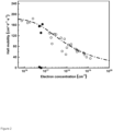
The electron Hall mobility of several samples of different origin using different techniques is show in this figure. Values being represented by open circles have a layer thickens of below 2 µm. The values for the electron Hall mobility represented by the closed squares represent experiments samples with a higher layer thickness (well above 2 µm) using the method which is known in the art. - The closed circles, however, represent values for the electron hall mobility with a higher layer thickness which were produced using the inventive method.
- The dash dotted line represents an empirical behavior of the Hall mobility versus electron concentration.
- Layers of β-Ga2O3 with a doping concentration of less than 5 × 1016 cm-3 (hence called unintentionally doped) and a crystal orientation of (100) were grown on both (100) Mg-doped semi-insulating substrates and Si-doped conductive substrates which were produced by the Czochralski method.
- Preferably, the substrates are polished. More preferably, the roughness after polishing is not more than 300 pm measured by atomic force microscope (AFM). The measured value is the root mean square of the deviation of an average height measured AFM.
- Preferably, after polishing the substrates are etched in an aqueous solution of phosphoric acid (H3PO4, preferably not less than 85 vol%) for at least 12 min and not more than 20 min. Best results were reached for 15 min to remove the damaged layer during the polishing.
- After polishing, the substrates are preferably annealed in an atmosphere consisting essentially of high purity oxygen at a temperature of not less than 850°C and not more than 950°C for preferably at least 1 hour to pronounce the terraced surface structure.
- The inventors used a metalorganic vapor phase epitaxy system comprising a vertical showerhead low-pressure reactor (Structured Materials Industries, Inc. -USA) equipped with a rotating susceptor, that was utilized to grow n-type β-Ga2O3 thin films. An example of the equipment used can be seen in
US 6 289 842 B1 . - Preferably, Triethylgallium (TEGa) is used as metalorganic precursors for Ga, while high purity O2 (5N) is preferably used as the oxidant and high purity Argon (5N) as the carrier gas.
- The preferred proportionate gas flow of the high purity argon is not less than 3000 sccm and not more than 10000 sccm. More preferably the proportionate gas flow is not less than 5000 sccm and not more than 8000 sccm.
- Preferably, the molar ration of the high-purity oxygen and the triethylgallium is more than 300 and less than 400.
- Preferably, the growth temperature is more than 800°C, preferred more than 825°C, and less than 850°C.
- Preferably, after the growth of the layer the wafer is annealed at a temperature of more than 10 K and less than 30K above the used growth temperature for not less than 2 h and not more than 4 h.
- Preferably, the ambient atmosphere for the said annealing essentially consists of Argon.
- After the annealing process is finished preferably a second growth step is started. The thickness of the layer can be increased without worsening the quality of the grown layer.
- The surface roughness of the grown films was characterized using atomic force microscopy (Bruker Dimension Icon, - the USA). The value for the surface roughness is given by the root mean square of a deviation of an average surface.
- The layer thickness and the dopant concentration profile were determined by the secondary ion mass spectrometry (SIMS) performed by RTG Mikroanalyse GmbH Berlin. The electrical properties of unintentionally-doped (UID) (100) β-Ga2O3 thin films were characterized via temperature-dependent resistivity and Hall measurements (HMS 7504, Lake Shore) in the van der Pauw configuration.
- Metal stack of Ti (50 nm)/Au (150 nm) ohmic contacts were deposited on the corners of the samples in vacuum under pressure of a few 10-6 mbar with electron beam evaporation. Afterwards, samples were subjected to a rapid thermal annealing at 470 °C for 1 min in N2 atmosphere to achieve a low on-contact resistance. The temperature was varied from 20 K to 320 K and excitation currents of 10 nA-1 µA were used.
- The inventors investigated the influence of the showerhead distance on the growth of β-Ga2O3 thin films.
- They realized that the layer growth rate increases nearly double by decreasing the showerhead distance from 80 mm to 15 mm while keeping the TEGa flow rate constant.
Table 1: Summary of some samples using different showerhead distances. Samples were all grown with a targeted thickness of around 3 µm. For these examples the growth temperature and the chamber pressure are kept constant at about 800 °C and 25 mbar, respectively. Sample Showerhead distance (mm) TEGa flux (sccm) Oxygen flux (sccm) Ar pushgas (sccm) Growth rate (nm/min) I 80 60 165 2900 5.5 II 15 60 165 2900 12 - Since the growth in the condition used is mass transport-limited, the thin film growth rate was primarily limited by the TEGa flow rate.
- The observed increase in thin-film growth rate suggested that a lower showerhead distance reduces the loss of TEGa during the gas-phase transportation from the showerhead to the susceptor.
- The preferred distance between the shower head and the surface of the substrate is more than 10 mm and less than 15mm.
- The inventors think, that since the oxygen amount remained constant, an increased growth rate indicates a lower VI/III ratio close to the surface compared with a higher showerhead distance, which is an advantage for the stability of the Ga wetting layer formation and helps to maintain step-flow morphology during the film growth.
- The desired step-flow morphology along the [001] direction could be observed under the inventive growth conditions.
- The surface roughness (RMS) was measured to be below 0.5 nm, which is lower than the MOVPE-grown (010) β-Ga2O3 at a similar thickness in both small (0.5 µm × 0.5 µm) and large scale (5 µm × 5 µm) AFM images.
- It should be noted that the inventive growth condition can be adapted to both Mg-doped substrates and Si-doped substrates grown in the same chamber, which enables the applications in the lateral and vertical device.
- Moreover, the inventors realized that a lower showerhead distance seems to minimize the unwanted gas phase reactions in the chamber by reducing the flight path of the precursor, which allows fewer parasitic particles to be formed, and a much cleaner grown surface can be observed.
- A comparison between the films grown under different showerhead distances by light microscopy is presented in
Figure 1 . - The inventors found parasitic particles to be pronounced at a higher thickness of the thin film (> 2 µm). On the one hand, such particles induce harmful, acceptor-like structural defects within the layer, which drops mobility down (even in some cases, Hall measurement is impossible) which makes the material useless for device manufacturing.
- In vertical device structure, it enhances reverse leakage current, which means blocking capability of Schottky barrier deteriorates. Therefore, detailed investigations and process optimizations are needed to understand the origin of such parasitic particles and how to eliminate them entirely.
- Another embodiment of this invention is an inventive semiconductor wafer which comprises a substrate having a front surface and said front surface being provided with a semiconductor layer of thickness d consisting essentially of β-Ga2O3
- Preferably, the doping concentration of the said layer is less than 5 × 1016 cm-3 measured by Hall measurement at room temperature using a van der Pauw measurement setup.
- The Hall mobility for the said layer measured at room temperature is preferably greater than 120 cm2V-1s-1 and the thickness d is greater than 3 µm measured by SIMS.
- More preferably, the surface particle density on the semiconductor layer is less than 900 cm-2 where the measurement having been carried out with optical microscopy.
- More preferably, a deviation of the thickness of the layer from the average thickness of the layer is less than 10% measured by ellipsometry and the surface roughness of the layer is no more than 600 pm measured by AFM. The surface roughness is expressed in the root mean square of the deviation of an average height of the AFM measurement.
- More preferably, the substrate is essentially of β-Ga2O3 having an electrical resistivity of less than 5 × 10⁻² Ohmcm at room temperature.
- The inventors realized that these substrates having the preferred layer of β-Ga2O3 suited very good to be used as a start material to build vertical devices.
- More preferably, the crystalline orientation of the layer is (100).
- Most preferably, the thickness d of the layer is greater than 3 µm and less than 6 µm. The measurement can be easily performed by a SIMS measurement.
Claims (11)
- A method of growing a layer of β-Ga2O3 on a substrate comprising the following steps:Polishing the substrate to a roughness of not more than 300 × 10-12 m measured by AFM,etching the substrate using an aqueous solution of phosphoric acid (H3PO4) for not less than 12 min and not more than 20 min, the aqueous solution having a phosphoric acid concentration of at least 85% by volume,annealing the substrate at not less than 850°C and not more than 950°C in an atmosphere consisting essentially of high purity oxygen,metalorganic vapor phase epitaxy in an apparatus for metalorganic vapor phase epitaxy comprising a shower head through which a gas stream is directed to the surface of the substrate, and wherein a distance between the shower head and the surface of the substrate is setwherein the gas stream comprises the components triethylgallium, high purity oxygen and high purity argon,characterized in thatthe distance between the shower head and the surface of the substrate is more than 10 mm and less than 15 mm, andthe proportionate gas flow of the high purity argon is not less than 3000 sccm and not more than 10000 sccmand the molar ratio of the high-purity oxygen and triethylgallium is more than 300 and less than 400.
- Method according to claim 1, characterized in that
the gas flow of the high purity argon is not less than 5000 sccm and not more than 8000 sccm. - Method according to claim 1, characterized in that
the growth temperature is more than 800°C, preferred more than 825°C, and less than 850°C. - Method according to claim 1, characterized in that
after growth of the layer the wafer is annealed at a temperature of more than 10K and less than 30K above the growth temperature for not less than 2 h and not more than 4 h. - Method according to claim 4, characterized in that
a second growth step is started after the annealing. - A semiconductor wafer comprising a substrate having a front surface,said front surface being provided with a semiconductor layer of thickness d consisting essentially of β-Ga2O3and the doping concentration of the layer is less than 5 × 1016 cm-3 measured by Hall measurement at room temperature using a van der Pauw measurement setup characterized in thatthe Hall mobility measured at room temperature is greater than 120 cm2V-1s-1 and the thickness d is greater than 3 µm measured by SIMS.
- A semiconductor wafer according to claim 6, characterized in that the surface particle density on the semiconductor layer is less than 900 / cm2 where the measurement having been carried out with optical microscopy.
- A semiconductor wafer according to claim 6 or claim 7 characterized in that a deviation of the thickness from the average thickness is less than 10% measured by ellipsometry and the surface roughness of the layer is not more than 600 pm measured by AFM.
- A semiconductor wafer according to any of claim 6 to claim 8, characterized in that the substrate is essentially of β-Ga2O3 having an electrical resistivity of less than 5 × 10⁻² Ohmcm at room temperature.
- A semiconductor wafer according to any of claim 6 to claim 9, characterized in that the crystalline orientation of the layer is (100).
- A semiconductor wafer according to claim 6, characterized in that the thickness d is greater than 3 µm and less than 6 µm measured by SIMS.
Priority Applications (6)
| Application Number | Priority Date | Filing Date | Title |
|---|---|---|---|
| EP22194558.7A EP4335949A1 (en) | 2022-09-08 | 2022-09-08 | Method for growing a gallium oxide layer on a substrate and semiconductor wafer |
| PCT/EP2023/073507 WO2024052149A1 (en) | 2022-09-08 | 2023-08-28 | Method for growing a gallium oxide layer on a substrate and semiconductor wafer |
| KR1020257007543A KR20250048079A (en) | 2022-09-08 | 2023-08-28 | Method for growing a gallium oxide layer on a substrate and a semiconductor wafer |
| JP2025514476A JP2025531845A (en) | 2022-09-08 | 2023-08-28 | Method for growing a gallium oxide layer on a substrate and semiconductor wafer |
| CN202380064471.6A CN120359326A (en) | 2022-09-08 | 2023-08-28 | Method for growing gallium oxide layer on substrate and semiconductor wafer |
| TW112133065A TW202411482A (en) | 2022-09-08 | 2023-08-31 | Method for growing a gallium oxide layer on a substrate and semiconductor wafer |
Applications Claiming Priority (1)
| Application Number | Priority Date | Filing Date | Title |
|---|---|---|---|
| EP22194558.7A EP4335949A1 (en) | 2022-09-08 | 2022-09-08 | Method for growing a gallium oxide layer on a substrate and semiconductor wafer |
Publications (1)
| Publication Number | Publication Date |
|---|---|
| EP4335949A1 true EP4335949A1 (en) | 2024-03-13 |
Family
ID=83232677
Family Applications (1)
| Application Number | Title | Priority Date | Filing Date |
|---|---|---|---|
| EP22194558.7A Pending EP4335949A1 (en) | 2022-09-08 | 2022-09-08 | Method for growing a gallium oxide layer on a substrate and semiconductor wafer |
Country Status (6)
| Country | Link |
|---|---|
| EP (1) | EP4335949A1 (en) |
| JP (1) | JP2025531845A (en) |
| KR (1) | KR20250048079A (en) |
| CN (1) | CN120359326A (en) |
| TW (1) | TW202411482A (en) |
| WO (1) | WO2024052149A1 (en) |
Families Citing this family (1)
| Publication number | Priority date | Publication date | Assignee | Title |
|---|---|---|---|---|
| CN119859790B (en) * | 2025-03-25 | 2025-07-01 | 蓝河科技(绍兴)有限公司 | Method for growing gallium oxide thin films |
Citations (1)
| Publication number | Priority date | Publication date | Assignee | Title |
|---|---|---|---|---|
| US6289842B1 (en) | 1998-06-22 | 2001-09-18 | Structured Materials Industries Inc. | Plasma enhanced chemical vapor deposition system |
Family Cites Families (4)
| Publication number | Priority date | Publication date | Assignee | Title |
|---|---|---|---|---|
| JP2005039123A (en) * | 2003-07-17 | 2005-02-10 | Renesas Technology Corp | Chemical vapor deposition equipment |
| JP2007254174A (en) * | 2006-03-20 | 2007-10-04 | Nippon Light Metal Co Ltd | Gallium oxide single crystal and manufacturing method thereof, nitride semiconductor substrate and manufacturing method thereof |
| JP5747110B1 (en) * | 2014-06-30 | 2015-07-08 | 株式会社タムラ製作所 | Ga2O3 single crystal substrate |
| US11624126B2 (en) * | 2020-06-16 | 2023-04-11 | Ohio State Innovation Foundation | Deposition of single phase beta-(AlxGa1-x)2O3 thin films with 0.28< =x<=0.7 on beta Ga2O3(100) or (−201) substrates by chemical vapor deposition |
-
2022
- 2022-09-08 EP EP22194558.7A patent/EP4335949A1/en active Pending
-
2023
- 2023-08-28 JP JP2025514476A patent/JP2025531845A/en active Pending
- 2023-08-28 KR KR1020257007543A patent/KR20250048079A/en active Pending
- 2023-08-28 WO PCT/EP2023/073507 patent/WO2024052149A1/en not_active Ceased
- 2023-08-28 CN CN202380064471.6A patent/CN120359326A/en active Pending
- 2023-08-31 TW TW112133065A patent/TW202411482A/en unknown
Patent Citations (1)
| Publication number | Priority date | Publication date | Assignee | Title |
|---|---|---|---|---|
| US6289842B1 (en) | 1998-06-22 | 2001-09-18 | Structured Materials Industries Inc. | Plasma enhanced chemical vapor deposition system |
Non-Patent Citations (3)
| Title |
|---|
| CHOU TA-SHUN ET AL: "Fast homoepitaxial growth of (100) [beta]-Ga2O3 thin films via MOVPE", AIP ADVANCES, AMERICAN INSTITUTE OF PHYSICS, 2 HUNTINGTON QUADRANGLE, MELVILLE, NY 11747, vol. 11, no. 11, 19 November 2021 (2021-11-19), XP012261364, DOI: 10.1063/5.0069243 * |
| MILLER ROSS ET AL: "Epitaxial $\beta$ -Ga2O3 and $\beta$ -(AlxGa1-x)2O3/ $\beta$ -Ga2O3 Heterostructures Growth for Power Electronics", IEEE TRANSACTIONS ON SEMICONDUCTOR MANUFACTURING, IEEE SERVICE CENTER, PISCATAWAY, NJ, US, vol. 31, no. 4, 1 November 2018 (2018-11-01), pages 467 - 474, XP011693163, ISSN: 0894-6507, [retrieved on 20181017], DOI: 10.1109/TSM.2018.2873488 * |
| T.-S. CHOUP. SEYIDOVS. BIN ANOOZR. GRUNEBERGT. THI THUY VIK. IRMSCHERM. ALBRECHTZ. GALAZKAJ. SCHWARZKOPFA. POPP, AIP ADV, vol. 11, 2021, pages 115323 |
Also Published As
| Publication number | Publication date |
|---|---|
| WO2024052149A1 (en) | 2024-03-14 |
| CN120359326A (en) | 2025-07-22 |
| KR20250048079A (en) | 2025-04-07 |
| TW202411482A (en) | 2024-03-16 |
| JP2025531845A (en) | 2025-09-25 |
Similar Documents
| Publication | Publication Date | Title |
|---|---|---|
| US7976630B2 (en) | Large-area seed for ammonothermal growth of bulk gallium nitride and method of manufacture | |
| TWI429797B (en) | Group III nitride semiconductor crystal substrate and semiconductor device | |
| US6447604B1 (en) | Method for achieving improved epitaxy quality (surface texture and defect density) on free-standing (aluminum, indium, gallium) nitride ((al,in,ga)n) substrates for opto-electronic and electronic devices | |
| US20020033521A1 (en) | Sapphire substrate, semiconductor device, electronic component, and crystal growing method | |
| US10923345B2 (en) | Epitaxial metal oxide as buffer for epitaxial III-V layers | |
| TWI819701B (en) | Method for producing a gallium oxide layer on a substrate | |
| EP3929336A1 (en) | Gan crystal and substrate | |
| US6255004B1 (en) | III-V nitride semiconductor devices and process for the production thereof | |
| US9543392B1 (en) | Transparent group III metal nitride and method of manufacture | |
| US7687379B2 (en) | Method of manufacturing In(As)Sb semiconductor on lattice-mismatched substrate and semiconductor device using the same | |
| WO2024052149A1 (en) | Method for growing a gallium oxide layer on a substrate and semiconductor wafer | |
| US20240355621A1 (en) | Semiconductor substrate, semiconductor wafer, and method for manufacturing semiconductor wafer | |
| EP4321659A1 (en) | Multilayer film structure and production method therefor | |
| EP2797108A1 (en) | Nitride semiconductor substrate | |
| US12406845B2 (en) | α-Ga2O3 semiconductor film | |
| EP3435407A1 (en) | Method for producing group iii nitride laminate | |
| JP6934473B2 (en) | Group III nitride semiconductor light emitting device | |
| WO1994016459A1 (en) | Semiconductor expitaxial substrate | |
| US20240401238A1 (en) | Laminate having group 13 element nitride single crystal substrate | |
| JP7797756B1 (en) | Epitaxial substrate and semiconductor element | |
| Buzynin et al. | Heteroepitaxial III–V films on fianite substrates and buffer layers |
Legal Events
| Date | Code | Title | Description |
|---|---|---|---|
| PUAI | Public reference made under article 153(3) epc to a published international application that has entered the european phase |
Free format text: ORIGINAL CODE: 0009012 |
|
| STAA | Information on the status of an ep patent application or granted ep patent |
Free format text: STATUS: THE APPLICATION HAS BEEN PUBLISHED |
|
| AK | Designated contracting states |
Kind code of ref document: A1 Designated state(s): AL AT BE BG CH CY CZ DE DK EE ES FI FR GB GR HR HU IE IS IT LI LT LU LV MC MK MT NL NO PL PT RO RS SE SI SK SM TR |
|
| STAA | Information on the status of an ep patent application or granted ep patent |
Free format text: STATUS: REQUEST FOR EXAMINATION WAS MADE |
|
| 17P | Request for examination filed |
Effective date: 20240821 |
|
| RBV | Designated contracting states (corrected) |
Designated state(s): AL AT BE BG CH CY CZ DE DK EE ES FI FR GB GR HR HU IE IS IT LI LT LU LV MC MK MT NL NO PL PT RO RS SE SI SK SM TR |