EP4335751A1 - Flügelexterne evakuierungspackbrettabdeckplatte und freisetzung einer weichen abdeckung mittels magnetostriktion - Google Patents
Flügelexterne evakuierungspackbrettabdeckplatte und freisetzung einer weichen abdeckung mittels magnetostriktion Download PDFInfo
- Publication number
- EP4335751A1 EP4335751A1 EP23195535.2A EP23195535A EP4335751A1 EP 4335751 A1 EP4335751 A1 EP 4335751A1 EP 23195535 A EP23195535 A EP 23195535A EP 4335751 A1 EP4335751 A1 EP 4335751A1
- Authority
- EP
- European Patent Office
- Prior art keywords
- actuator
- magnetostriction material
- spindle
- signal
- magnetostriction
- Prior art date
- Legal status (The legal status is an assumption and is not a legal conclusion. Google has not performed a legal analysis and makes no representation as to the accuracy of the status listed.)
- Pending
Links
Images


Classifications
-
- B—PERFORMING OPERATIONS; TRANSPORTING
- B64—AIRCRAFT; AVIATION; COSMONAUTICS
- B64D—EQUIPMENT FOR FITTING IN OR TO AIRCRAFT; FLIGHT SUITS; PARACHUTES; ARRANGEMENT OR MOUNTING OF POWER PLANTS OR PROPULSION TRANSMISSIONS IN AIRCRAFT
- B64D25/00—Emergency apparatus or devices, not otherwise provided for
- B64D25/08—Ejecting or escaping means
- B64D25/14—Inflatable escape chutes
Definitions
- the present disclosure relates to systems and methods for off-wing evacuation systems, and more specifically, to utilizing magnetostriction to control a packboard cover and softcover release of an aircraft.
- Aircraft emergency landings often demand rapid evacuation of passengers from the aircraft due to potential injuries from fire, explosions, and sinking in water.
- Quickly evacuating passengers from an aircraft is performed with multiple emergency exits, each equipped with evacuation slides or slides/rafts. Evacuation slides or slides/rafts are needed to comply with aviation regulation and to ensure the safe evacuation of all passengers.
- a system for releasing a blowout panel and softcover release of an evacuation slide in an aircraft includes a first actuator; a second actuator; and a controller, where the controller is configured to: receive an indication that an evacuation event has begun; and, responsive to receiving the indication of the evacuation event beginning: send a first signal to the first actuator that magnetizes a first magnetostriction material within the first actuator, thereby releasing the blowout panel of a packboard compartment in which the evacuation slide is present; and send a second signal to the second actuator that magnetizes a second magnetostriction material within the second actuator, thereby releasing a key-loop of lacing associated with the softcover in which the evacuation slide is present in the packboard compartment.
- the first actuator is a set of first actuators.
- the first actuator includes: the first magnetostriction material; a spindle; and a set of ball bearings, where the first magnetostriction material, when magnetized, expands along a length of the first magnetostriction material in a first direction forcing the spindle to translate in the first direction thereby allowing the set of ball bearings holding the blowout panel in place to translate in a second direction perpendicular to the first direction thereby releasing the blowout panel.
- the first actuator further includes a compression spring, where the compression spring provides a compression spring force that holds the spindle against the first magnetostriction material.
- the first actuator further includes a solenoid, where the solenoid generates a magnetic field in response to receiving the first signal and where the magnetic field magnetizes the first magnetostriction material thereby expanding the first magnetostriction material along the length of the first magnetostriction material in the first direction.
- the first signal is a direct current signal.
- the second actuator includes: the second magnetostriction material; and a spindle, where the second magnetostriction material, when magnetized, expands along a length of the second magnetostriction material in a first direction forcing the spindle to translate in the first direction thereby pulling the key-loop of the lacing coupled to the spindle.
- the second actuator further includes a compression spring, where the compression spring provides a compression spring force that holds the spindle against the second magnetostriction material.
- the second actuator further includes a solenoid, where the solenoid generates a magnetic field in response to receiving the second signal and where the magnetic field magnetizes the second magnetostriction material thereby expanding the second magnetostriction material along the length of the second magnetostriction material in the first direction.
- the second signal is a direct current signal.
- control system for releasing a blowout panel and softcover release of an evacuation slide in an aircraft.
- the control system includes: a first actuator; a second actuator; and a controller coupled to the first actuator and the second actuator; and a tangible, non-transitory memory configured to communicate with the controller, the tangible, non-transitory memory having instructions stored thereon that, in response to execution by the controller, cause the controller to perform operations including: receiving an indication that an evacuation event has begun; and, responsive to receiving the indication of the evacuation event beginning: sending a first signal to the first actuator that magnetizes a first magnetostriction material within the first actuator, thereby releasing the blowout panel of a packboard compartment in which the evacuation slide is present; and sending a second signal to the second actuator that magnetizes a second magnetostriction material within the second actuator, thereby releasing a key-loop of lacing associated with the softcover in which the evacuation slide is present in the packboard compartment.
- the first actuator is a set of first actuators.
- the first actuator including: the first magnetostriction material; a spindle; and a set of ball bearings, where the first magnetostriction material, when magnetized, expands along a length of the first magnetostriction material in a first direction forcing the spindle to translate in the first direction thereby allowing the set of ball bearings holding the blowout panel in place to translate in a second direction perpendicular to the first direction thereby releasing the blowout panel.
- the first actuator further includes a compression spring, where the compression spring provides a compression spring force that holds the spindle against the first magnetostriction material.
- the first actuator further includes a solenoid, where the solenoid generates a magnetic field in response to receiving the first signal and where the magnetic field magnetizes the first magnetostriction material thereby expanding the first magnetostriction material along the length of the first magnetostriction material in the first direction.
- the second actuator includes: the second magnetostriction material; and a spindle, where the second magnetostriction material, when magnetized, expands along a length of the second magnetostriction material in a first direction forcing the spindle to translate in the first direction thereby pulling the key-loop of the lacing coupled to the spindle.
- the second actuator further includes a compression spring, where the compression spring provides a compression spring force that holds the spindle against the second magnetostriction material.
- the second actuator further includes a solenoid, where the solenoid generates a magnetic field in response to receiving the second signal and where the magnetic field magnetizes the second magnetostriction material thereby expanding the second magnetostriction material along the length of the second magnetostriction material in the first direction.
- the first signal and the second signal are direct current signals.
- the method includes, the method including receiving, by a controller, an indication that an evacuation event has begun; and, responsive to receiving the indication of the evacuation event beginning: sending, by the controller, a first signal to a first actuator that magnetizes a first magnetostriction material within the first actuator, thereby releasing the blowout panel of a packboard compartment in which the evacuation slide is present; and sending, by the controller, a second signal to a second actuator that magnetizes a second magnetostriction material within the second actuator, thereby releasing a key-loop of lacing associated with the softcover in which the evacuation slide is present in the packboard compartment.
- references to "a,” “an,” or “the” may include one or more than one and that reference to an item in the singular may also include the item in the plural. Further, all ranges may include upper and lower values and all ranges and ratio limits disclosed herein may be combined.
- Existing evacuation slide release systems for the blowout panel and soft cover include a gas delivery manifold.
- the release source is pressurized gas from reservoir tank stored along with packboard compartment and the pressurized gas is configured to flow into delivery manifolds in response to an evacuation event.
- the ball locks associated with the blowout panel are configured to release the blowout panel and actuator pins associated with the softcover are configured to release the softcover covering the evacuation slide or slide/raft within the packboard compartment in response to pressurized gas flow to from the gas delivery manifolds.
- future evacuation slide release systems may be configured to run on electricity instead of using compressed gas and sub-systems within the aircraft are planned to operate via an electric source, which means that gas delivery manifold release systems for blowout panels and soft covers needs to be replaced.
- gas delivery manifold release systems for blowout panels and soft covers needs to be replaced.
- Disclosed herein is a system and method for utilizing magnetostriction to control a packboard cover and softcover release of an aircraft.
- the system and method disclosed herein uses a magnetostriction component which has the property of ferromagnetic (materials that causes the magnetostriction component to change their shape or dimensions during the process of magnetization) and generates the magnetic field when electrically energized to achieve the functionality of the ball locks and actuator pins release system to replace the existing gas-based delivery manifold release system.
- the aircraft 100 may include comprise a fuselage 102 with wings 104 fixed to fuselage 102.
- Emergency exit door 106 may be disposed on the fuselage 102 over the wings 104 such that passengers exiting emergency exit door 106 would exit onto wings 104.
- An evacuation slide assembly 108 may be disposed aft of emergency exit door 106.
- Blowout panel 110 may cover evacuation slide assembly 108 when installed on the aircraft 100.
- the evacuation slide assembly 108 may include and/or be housed within a packboard compartment to the aircraft 100.
- the evacuation slide assembly 108 may jettison the blowout panel 110 and deploy an evacuation slide, such as an inflatable slide, in response to an activated emergency exit door 106 opening or in response to another evacuation event.
- the evacuation slide may be packed within and/or otherwise stored and/or retained within a soft cover.
- the evacuation slide assembly 108 may include a release system that facilitates the deployment of the evacuation slide and the release of both the blowout panel 110 and the soft cover.
- the release system may be actuated using a single power source, such as a magnetostriction component.
- actuation of the release system, and thus deployment of the evacuation slide and the deployment/release of both the blowout panel 110 and the soft cover may be non-electrically actuated.
- a first actuator 202 is configured to release the blowout panel 110 of the evacuation slide assembly 108 of FIG. 1 in response to an evacuation event. That is, according to various embodiments, the blowout panel 110 may be at least partially retained in place by the first actuator 202 until an evacuation event. In response to the evacuation event, the first actuator 202 may release the blowout panel 110, thus allowing the blowout panel 110 to be jettisoned, in accordance with various embodiments. In various embodiments, the act of j ettisoning of the blowout panel 110 may be accomplished indirectly via inflation of the evacuation slide.
- the first actuator 202 may include multiple actuators spaced apart from each other and distributed along a length of the packboard compartment 204.
- the first actuator 202 or first actuators may be ball locks. The ball locks may engage a lip or other surface of the blowout panel 110 and thus may securely retain, or at least facilitate retaining, the blowout panel 110 in place over an opening to the packboard compartment 204.
- the first actuator 202 or first actuators release the blowout panel 110.
- the packboard compartment 204 may include comprise a soft cover 206 containing evacuation slide 208.
- Soft cover 206 may have lacing 210 to enclose the soft cover 206 and to retain the evacuation slide 208.
- the lacing 210 may be in a daisy chain or speed lacing configuration.
- the lacing 210 may have a key-loop that, once released or unlocked, allows the remainder of the lacing 210 to be unfurled.
- the evacuation slide 208 may be released (or may at least be releasable).
- a second actuator 212 may be coupled to the lacing 210 and motivation of the second actuator 212, in response to an evacuation event, may unlock the key-loop or other such feature of the lacing 210, thereby allowing the lacing 210 to be unfurled.
- the lacing 210 may include a pin that locks the key-loop. The pin may be slidably coupled to the lacing 210 and may be coupled to the second actuator 212. Movement of the second actuator 212 may cause the pin 214 to translate or slide into the second actuator 212, thus unlocking the lacing 210.
- the second actuator 212 may also include an arm that is configured to couple to the key-loop or pin of the lacing 210.
- the arm of the second actuator 212 may be in an extended position when an evacuation event is not occurring or when the evacuation system is disarmed.
- the arm of the second actuator 212 retracts into a housing, thus sliding the pin or otherwise unlocking the key-loop of the lacing 210 to allow the lacing 210 to unfurl and release the evacuation slide 208 from the soft cover 206.
- the evacuation slide assembly 108 includes the evacuation slide 208 stored in an uninflated condition within a packboard compartment 204.
- the packboard compartment 204 itself is secured within a recess 302 in the outer hull of the aircraft 100 and covered by the blowout panel 110 that is seated in reveal 304 so that the blowout panel 110 is flush with and conforms to the general contour of the outer hull of aircraft 100.
- the blowout panel 110 is secured to packboard compartment 204 by means of a first actuator 202 or set of first actuators the operation of which is explained more fully hereinafter.
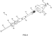
- the ball lock assembly 400 of FIG. 4 may be a first actuator such as the first actuator 202 of FIG. 2 .
- the ball lock assembly 400 includes a frangible rod 402, a nose 404, ball bearings 406, a nose fitting 408, a magnetostrictive housing 410, a drive rod 412, a spindle 414, a compression spring 416, an actuator housing 418, a washer 420, and a nut 422.
- the magnetostrictive housing 410 includes a direct current solenoid that is coupled to a controller via an electrical cable connection 424.
- the drive rod 412 which is configured to fit within the magnetostrictive housing 410, is comprised of the magnetostriction component.
- the magnetostriction component is a ferromagnetic material such as Terfenol-D (an alloy including Terbium, Dysprosium, and Iron), Nickel, Alfer (Fe-Al alloy), Permalloy (Fe-Ni alloy), Cobalt-Nickel (Co-Ni alloy), Permendur (Co-Fe-V alloy); Cobalt Ferrite (CoFe 2 O 4 ), Nickel Ferrite (NiFe 2 O 4 ), the preceding with or without various rare earths and their alloys and compounds, among others.
- the magnetostriction component has the property of a material that causes the material to change shape or dimensions during the process of magnetization.
- a magnetic field is generated that causes the drive rod 412 to change shape or dimensions.
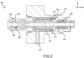
- the spindle 414 of the ball lock assembly 400 comprises a proximal end 504 and a distal end 506.
- the compression spring 416 in the locked state, is in a default length state that applies a compression spring force 502 in a first direction, i.e., in a negative x-direction, to a first face of the proximal end 504 of the spindle 414.
- the compression spring force 502 forces the distal end 506 of the spindle 414 to abut the nose fitting 408 which forces ball bearings 406 in an outward direction 508, i.e., a positive and negative y-direction.
- the drive rod 412 abuts a second face of the proximal end 504 of the spindle 414.
- the magnetostriction material of the drive rod 412 is not exposed to a magnetic field from the direct current solenoid 510 within the magnetostrictive housing 410 due to no electrical signal being provided via the electrical cable connection 424 by the controller.
- the magnetostriction material of the drive rod 412 is not electrically energized and in a non-magnetic phase. Accordingly, in various embodiments, a structure of the magnetostriction material of the drive rod 412 is randomly oriented and does not change its shape. In that regard, the length of the drive rod 412 does not change during non-magnetic phase and the spindle 414 stays in specified position due to the compression spring force 502 and ensures that ball bearings 406 protrude outside the periphery of the nose fitting 408. Thus, the ball lock assembly 400 retains the blowout panel 110 of FIG. 1 within the desired position.
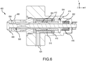
- the controller in the unlocked/released state of the ball lock assembly 400, is configured to provide an electrical signal to the direct current solenoid 510 within the magnetostrictive housing 410 via the electrical cable connection 424.
- the direct current solenoid 510 with the provided electrical signal, the direct current solenoid 510 generates a magnetic field onto the drive rod 412.
- a structure of the magnetostriction material in the drive rod 412 changes orientation.
- the orientation change imposed by the magnetic field generated by the direct current solenoid 510 creates a strain field in the magnetostriction material of the drive rod 412 and, as the intensity of the magnetic field is increased, more and more magnetic domains of magnetostriction material orientate themselves so that their principle axes of anisotropy are collinear with the magnetic field in each region and finally saturation is achieved.
- the effect of this material property change in the magnetostriction material of the drive rod 412 during magnetic field phase causes the drive rod 412 to increase in length in a second direction 602 opposite to the compression spring force 502 of FIG. 5 , i.e., in a positive x-direction, which increases a length of the drive rod 412 from its original length by reducing its diameter respectively.
- the elongation of the drive rod 412 in the second direction 602 causes the drive rod 412, which abuts the second face of the proximal end 504 of the spindle 414, to force the spindle 414 to translate in the second direction 602, i.e., in the positive x-direction, which compresses the compression spring 416 in the second direction 602, i.e., in the positive x-direction.
- the longitudinal strain of in the magnetostriction material of the drive rod 412 produces the tensile force which creates the pushing force on the second face of the proximal end 504 of the spindle 414.
- the proximal end 504 of the spindle 414 translates towards the compression spring 416 due to increase length of the drive rod 412.
- the increased length of drive rod 412 generates a force that is higher than the compression spring force 502 such that the distal end 506 of the spindle 414 gradually moves away from a position of the ball bearings 406.
- the displacement of the spindle 414 allows the ball bearings 406 to retract in an inward direction 604 opposite the outward direction 508 of FIG. 5 , i.e., a negative and positive y-direction, to inside the periphery of the nose fitting 408. Accordingly, this process allows the blowout panel 110 of FIG. 1 to release from its locked position as the ball bearings 406 being retracted provides space for cover panel to move from a locked position.
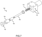
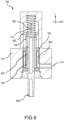
- the pull pin assembly 700 of FIG. 7 may be a second actuator such as the second actuator 212 of FIG. 2 .
- the pull pin assembly 700 includes a nose fitting 702, a magnetostrictive housing 704, a drive rod 706, a spindle 708, a compression spring 710, and an actuator housing 712.
- the magnetostrictive housing 704 includes a direct current solenoid that is coupled to a controller via an electrical cable connection 714.
- the drive rod 706, which is configured to fit within the magnetostrictive housing 704, is comprised of the magnetostriction component.
- the magnetostriction component is a ferromagnetic material such as Terfenol-D (an alloy including Terbium, Dysprosium, and Iron), Nickel, Alfer (Fe-Al alloy), Permalloy (Fe-Ni alloy), Cobalt-Nickel (Co-Ni alloy), Permendur (Co-Fe-V alloy); Cobalt Ferrite (CoFe 2 O 4 ), Nickel Ferrite (NiFe 2 O 4 ), the preceding with or without various rare earths and their alloys and compounds, among others.
- the magnetostriction component has the property of a material that causes the material to change shape or dimensions during the process of magnetization.
- the controller which is configured to provide a direct current signal to the direct current solenoid of the magnetostrictive housing 704 via the electrical cable connection 714, providing a direct current signal to the direct current solenoid, a magnetic field is generated that causes the drive rod 706 to change shape or dimensions.
- the spindle 708 of the pull pin assembly 700 comprises a proximal end 802 and a distal end 804.
- the compression spring 710 in the locked state, is in a default length state that applies a compression spring force 806 in a first direction, i.e., in a negative y-direction, to a first face of the proximal end 802 of the spindle 708.
- the compression spring force 806 forces a second face of the proximal end 802 of the spindle 708 to abut a first end of the drive rod 706.
- the magnetostriction material of the drive rod 706 is not exposed to a magnetic field from a direct current solenoid 808 within the magnetostrictive housing 704 due to no electrical signal being provided via the electrical cable connection 714 by the controller. In that regard, the magnetostriction material of the drive rod 706 is not electrically energized and in a non-magnetic phase. Accordingly, in various embodiments, a structure of the magnetostriction material of the drive rod 706 is randomly oriented and does not change its shape.
- the length of the drive rod 706 does not change during non-magnetic phase and the spindle 708 stays in specified position due to the compression spring force 806. Accordingly, the distal end 804 of the spindle 708, which is coupled to the lacing loops of the soft cover 206 of FIG. 2 stays intact with the lacing 210 of FIG. 2 and thus, does not release lacing 210 of the soft cover 206.
- the controller in the unlocked/released state of the pull pin assembly 700, is configured to provide an electrical signal to the direct current solenoid 808 within the magnetostrictive housing 704 via the electrical cable connection 714.
- the direct current solenoid 808 with the provided electrical signal, the direct current solenoid 808 generates a magnetic field onto the drive rod 706.
- a structure of the magnetostriction material in the drive rod 706 changes orientation.
- the orientation change imposed by the magnetic field generated by the direct current solenoid 808 creates a strain field in the magnetostriction material of the drive rod 706 and, as the intensity of the magnetic field is increased, more and more magnetic domains of magnetostriction material orientate themselves so that their principle axes of anisotropy are collinear with the magnetic field in each region and finally saturation is achieved.
- the effect of this material property change in the magnetostriction material of the drive rod 706 during magnetic field phase causes the drive rod 706 to increase in length in a second direction 902 opposite to the compression spring force 806 of FIG. 5 , i.e., in a positive y-direction, which increases a length of the drive rod 706 from its original length by reducing its diameter respectively.
- the elongation of the drive rod 706 in the second direction 902 causes the drive rod 706, which abuts the second face of the proximal end 802 of the spindle 708, to force the spindle 708 to translate in the second direction 902, i.e., in the positive y-direction, which compresses the compression spring 710 in the second direction 902, i.e., in the positive y-direction.
- the longitudinal strain of in the magnetostriction material of the drive rod 706 produces the tensile force which creates the pushing force on the second face of the proximal end 802 of the spindle 708.
- the proximal end 802 of the spindle 708 translates towards the compression spring 710 due to increase length of the drive rod 706.
- the increased length of drive rod 706 generates a force that is higher than the compression spring force 806 such that the distal end 804 of the spindle 708 gradually moves into the actuator housing 712.
- the displacement of the spindle 708 pulls the lacing 210 that is coupled to the distal end 804 of the spindle 708 thereby untying the lacing 210 of the soft cover 206 and facilitate the deployment of an evacuation slide.
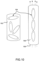
- non-magnetized magnetostriction material 1002 i.e., magnetostriction material that has not been exposed to an electrical signal and is in a non-magnetic phase
- magnetic dipoles 1004 within the non-magnetized magnetostriction material 1002 are randomly oriented.
- a magnetized magnetostriction material 1006 i.e., magnetostriction material that has been exposed to an electrical signal and is in magnetic phase
- magnetic dipoles 1004 orientate themselves so that their principle axes of anisotropy are collinear with magnetic field 1008 in each region until saturation is achieved.
- the effect of this material property change in the magnetized magnetostriction material 1006 during magnetic field phase causes the magnetostriction material 1006 to increase in length and decrease in width.
- controller 1102 receives input 1104 of an activated emergency exit door being opened, a signal from the cockpit of the aircraft, or other evacuation event, among others, that an evacuation event has begun.
- the controller 1102 is configured to provide a direct current signal to one or more first actuators, such as first actuator 202 of FIG. 2 or ball lock assembly 400 of FIGs. 4-6 , the one or more first actuators operating in the manner described with respect to FIGs. 4-6 .
- the controller 1102 is configured to provide a direct current signal to a second actuator, such as the second actuator 212 of FIG. 2 or pull pin assembly 700 of FIGs. 7-9 , the second actuator operating in the manner described with respect to FIG. s 7-9.
- a second actuator such as the second actuator 212 of FIG. 2 or pull pin assembly 700 of FIGs. 7-9 , the second actuator operating in the manner described with respect to FIG. s 7-9.
- the method 1200 may be performed by a controller 1102 described above with respect to FIG. 11 .
- the controller 1102 receives input of an activated emergency exit door being opened, a signal from the cockpit of the aircraft, or other evacuation event, among others, that an evacuation event is has begun.
- the controller 1102 is configured to provide a direct current signal to one or more first actuators that magnetizes a magnetostriction material within the one or more first actuators thereby releasing the blowout panel of a packboard compartment in which an evacuation slide or slide/raft is present.
- the controller 1102 is configured to provide a direct current signal to a second actuator that magnetizes a magnetostriction material within the second actuator thereby releasing a key-loop of lacing associated with a softcover in which the evacuation slide or slide/raft is present in the packboard compartment.
- references to "one embodiment,” “an embodiment,” “various embodiments,” etc. indicate that the embodiment described may include a particular feature, structure, or characteristic, but every embodiment may not necessarily include the particular feature, structure, or characteristic. Moreover, such phrases are not necessarily referring to the same embodiment. Further, when a particular feature, structure, or characteristic is described in connection with an embodiment, it is submitted that it is within the knowledge of one skilled in the art to affect such feature, structure, or characteristic in connection with other embodiments whether or not explicitly described. After reading the description, it will be apparent to one skilled in the relevant art(s) how to implement the disclosure in alternative embodiments.
- Numbers, percentages, or other values stated herein are intended to include that value, and also other values that are about or approximately equal to the stated value, as would be appreciated by one of ordinary skill in the art encompassed by various embodiments of the present disclosure.
- a stated value should therefore be interpreted broadly enough to encompass values that are at least close enough to the stated value to perform a desired function or achieve a desired result.
- the stated values include at least the variation to be expected in a suitable industrial process, and may include values that are within 10%, within 5%, within 1%, within 0.1%, or within 0.01% of a stated value.
- the terms “substantially,” “about,” or “approximately” as used herein represent an amount close to the stated amount that still performs a desired function or achieves a desired result.
- the term “substantially,” “about,” or “approximately” may refer to an amount that is within 10% of, within 5% of, within 1% of, within 0.1% of, and within 0.01% of a stated amount or value
Landscapes
- Business, Economics & Management (AREA)
- Emergency Management (AREA)
- Engineering & Computer Science (AREA)
- Aviation & Aerospace Engineering (AREA)
- General Electrical Machinery Utilizing Piezoelectricity, Electrostriction Or Magnetostriction (AREA)
Applications Claiming Priority (2)
| Application Number | Priority Date | Filing Date | Title |
|---|---|---|---|
| IN202241051631 | 2022-09-09 | ||
| US17/985,391 US12497180B2 (en) | 2022-09-09 | 2022-11-11 | Off-wing evacuation packboard cover panel and soft cover release utilizing magnetostriction |
Publications (1)
| Publication Number | Publication Date |
|---|---|
| EP4335751A1 true EP4335751A1 (de) | 2024-03-13 |
Family
ID=87933796
Family Applications (1)
| Application Number | Title | Priority Date | Filing Date |
|---|---|---|---|
| EP23195535.2A Pending EP4335751A1 (de) | 2022-09-09 | 2023-09-05 | Flügelexterne evakuierungspackbrettabdeckplatte und freisetzung einer weichen abdeckung mittels magnetostriktion |
Country Status (1)
| Country | Link |
|---|---|
| EP (1) | EP4335751A1 (de) |
Citations (3)
| Publication number | Priority date | Publication date | Assignee | Title |
|---|---|---|---|---|
| US20050001704A1 (en) * | 2000-10-03 | 2005-01-06 | Teruo Maruyama | Electromagnetostrictive actuator |
| US20200010204A1 (en) * | 2018-07-06 | 2020-01-09 | Goodrich Corporation | Systems and methods for soft cover attachment |
| US20210230906A1 (en) * | 2020-01-24 | 2021-07-29 | Goodrich Corporation | Position indicator for ball lock |
-
2023
- 2023-09-05 EP EP23195535.2A patent/EP4335751A1/de active Pending
Patent Citations (3)
| Publication number | Priority date | Publication date | Assignee | Title |
|---|---|---|---|---|
| US20050001704A1 (en) * | 2000-10-03 | 2005-01-06 | Teruo Maruyama | Electromagnetostrictive actuator |
| US20200010204A1 (en) * | 2018-07-06 | 2020-01-09 | Goodrich Corporation | Systems and methods for soft cover attachment |
| US20210230906A1 (en) * | 2020-01-24 | 2021-07-29 | Goodrich Corporation | Position indicator for ball lock |
Similar Documents
| Publication | Publication Date | Title |
|---|---|---|
| US10829230B2 (en) | Release system for evacuation slide assembly | |
| EP3835211B1 (de) | Elektromagnetisch betätigte module für aufblassysteme und deren montageverfahren | |
| CA2919505C (en) | Soft cover release mechanism for evacuation slides | |
| US12146349B2 (en) | Lever-lock release systems and methods | |
| US11235883B2 (en) | Evacuation slide restraint | |
| EP4335751A1 (de) | Flügelexterne evakuierungspackbrettabdeckplatte und freisetzung einer weichen abdeckung mittels magnetostriktion | |
| US12497180B2 (en) | Off-wing evacuation packboard cover panel and soft cover release utilizing magnetostriction | |
| EP0303628B1 (de) | Verfahren zur verbesserung der mannschaftsicherheit während eines flugkörperabschuss und verbesserung der verbindung für feststofftriebwerksegmente | |
| CA2259321A1 (en) | Load securing and releasing system | |
| CA2944108C (en) | Systems and devices for installing an evacuation slide actuation cable in a connection box assembly of an emergency evacuation slide and overwing door actuation system interface | |
| DE102011016208A1 (de) | Flugzeug und Flugdatenschreiber für ein Flugzeug | |
| EP3939889A1 (de) | Lastverstellbarer und wiederverwendbarer mechanischer halter für flugzeugevakuierungsrutschen-/-flosssysteme | |
| EP4242110A1 (de) | Federaktivierte kugelsperre auf formgedächtnislegierungsbasis und aktuatorstiftfreisetzungssysteme und -verfahren | |
| US11851195B2 (en) | Shape memory alloy based spring activated ball lock and actuator pin release systems and methods | |
| EP4279781A1 (de) | Elektromagnetisch betätigter druckregler für ein aufblassystem | |
| US20220196179A1 (en) | Dual solenoid initiator valve for compressed fluid sources | |
| US12448132B2 (en) | Slide pack growth detection method of evacuation slides or slide/rafts | |
| EP4506256A1 (de) | Verfahren zur erkennung des wachstums von objektträgern oder objektträgern/rafts | |
| EP4027050B1 (de) | Doppelmagnetinitiatorventil für druckfluidquellen | |
| US12187417B2 (en) | Retractable landing gear system with magnetic uplocks | |
| US20250368337A1 (en) | Evacuation slide/raft daisy chain release mechanism | |
| EP4279389A1 (de) | Solenoidbetätigte druckpatrone für ein aufblassystem | |
| CN117881600A (zh) | 不依赖于力的可释放系统 | |
| WO2025128094A1 (en) | System and method for packing inflatable safety equipment | |
| JP2007107796A (ja) | 接続及び分離装置 |
Legal Events
| Date | Code | Title | Description |
|---|---|---|---|
| PUAI | Public reference made under article 153(3) epc to a published international application that has entered the european phase |
Free format text: ORIGINAL CODE: 0009012 |
|
| STAA | Information on the status of an ep patent application or granted ep patent |
Free format text: STATUS: THE APPLICATION HAS BEEN PUBLISHED |
|
| AK | Designated contracting states |
Kind code of ref document: A1 Designated state(s): AL AT BE BG CH CY CZ DE DK EE ES FI FR GB GR HR HU IE IS IT LI LT LU LV MC ME MK MT NL NO PL PT RO RS SE SI SK SM TR |
|
| STAA | Information on the status of an ep patent application or granted ep patent |
Free format text: STATUS: REQUEST FOR EXAMINATION WAS MADE |
|
| 17P | Request for examination filed |
Effective date: 20240909 |
|
| RBV | Designated contracting states (corrected) |
Designated state(s): AL AT BE BG CH CY CZ DE DK EE ES FI FR GB GR HR HU IE IS IT LI LT LU LV MC ME MK MT NL NO PL PT RO RS SE SI SK SM TR |
|
| STAA | Information on the status of an ep patent application or granted ep patent |
Free format text: STATUS: EXAMINATION IS IN PROGRESS |
|
| 17Q | First examination report despatched |
Effective date: 20250716 |
|
| GRAP | Despatch of communication of intention to grant a patent |
Free format text: ORIGINAL CODE: EPIDOSNIGR1 |
|
| STAA | Information on the status of an ep patent application or granted ep patent |
Free format text: STATUS: GRANT OF PATENT IS INTENDED |
|
| INTG | Intention to grant announced |
Effective date: 20251211 |