EP4335682A2 - System and method for in-line wireless energy transfer and sensing in an independent cart system - Google Patents
System and method for in-line wireless energy transfer and sensing in an independent cart system Download PDFInfo
- Publication number
- EP4335682A2 EP4335682A2 EP23183114.0A EP23183114A EP4335682A2 EP 4335682 A2 EP4335682 A2 EP 4335682A2 EP 23183114 A EP23183114 A EP 23183114A EP 4335682 A2 EP4335682 A2 EP 4335682A2
- Authority
- EP
- European Patent Office
- Prior art keywords
- track
- coil
- mover
- energy transfer
- movers
- Prior art date
- Legal status (The legal status is an assumption and is not a legal conclusion. Google has not performed a legal analysis and makes no representation as to the accuracy of the status listed.)
- Pending
Links
- 238000012546 transfer Methods 0.000 title claims abstract description 98
- 238000000034 method Methods 0.000 title claims description 22
- 230000003993 interaction Effects 0.000 claims abstract description 11
- 230000005672 electromagnetic field Effects 0.000 claims abstract description 10
- 230000033001 locomotion Effects 0.000 claims description 18
- 230000005540 biological transmission Effects 0.000 claims description 5
- 238000000605 extraction Methods 0.000 description 9
- 230000008878 coupling Effects 0.000 description 5
- 238000010168 coupling process Methods 0.000 description 5
- 238000005859 coupling reaction Methods 0.000 description 5
- 230000005291 magnetic effect Effects 0.000 description 5
- 230000008569 process Effects 0.000 description 5
- 238000004146 energy storage Methods 0.000 description 4
- 238000004519 manufacturing process Methods 0.000 description 4
- 239000003990 capacitor Substances 0.000 description 3
- 238000005516 engineering process Methods 0.000 description 3
- 238000012986 modification Methods 0.000 description 3
- 230000004048 modification Effects 0.000 description 3
- 238000012163 sequencing technique Methods 0.000 description 3
- 230000008901 benefit Effects 0.000 description 2
- 239000004020 conductor Substances 0.000 description 2
- 238000010276 construction Methods 0.000 description 2
- 230000008030 elimination Effects 0.000 description 2
- 238000003379 elimination reaction Methods 0.000 description 2
- 230000004907 flux Effects 0.000 description 2
- 230000004044 response Effects 0.000 description 2
- 241000411998 Gliricidia Species 0.000 description 1
- 235000009664 Gliricidia sepium Nutrition 0.000 description 1
- 230000005355 Hall effect Effects 0.000 description 1
- XUIMIQQOPSSXEZ-UHFFFAOYSA-N Silicon Chemical compound [Si] XUIMIQQOPSSXEZ-UHFFFAOYSA-N 0.000 description 1
- 230000001133 acceleration Effects 0.000 description 1
- 230000004913 activation Effects 0.000 description 1
- 238000013459 approach Methods 0.000 description 1
- 230000009286 beneficial effect Effects 0.000 description 1
- 238000004891 communication Methods 0.000 description 1
- 239000012141 concentrate Substances 0.000 description 1
- 238000001514 detection method Methods 0.000 description 1
- 238000011161 development Methods 0.000 description 1
- 238000004134 energy conservation Methods 0.000 description 1
- 239000003302 ferromagnetic material Substances 0.000 description 1
- 230000006870 function Effects 0.000 description 1
- 230000009191 jumping Effects 0.000 description 1
- 238000003754 machining Methods 0.000 description 1
- 239000000463 material Substances 0.000 description 1
- 238000012544 monitoring process Methods 0.000 description 1
- 238000004806 packaging method and process Methods 0.000 description 1
- 230000035699 permeability Effects 0.000 description 1
- 239000013641 positive control Substances 0.000 description 1
- 238000012545 processing Methods 0.000 description 1
- 229910052710 silicon Inorganic materials 0.000 description 1
- 239000010703 silicon Substances 0.000 description 1
- 239000007787 solid Substances 0.000 description 1
- 238000003860 storage Methods 0.000 description 1
Images


Classifications
-
- H—ELECTRICITY
- H02—GENERATION; CONVERSION OR DISTRIBUTION OF ELECTRIC POWER
- H02J—CIRCUIT ARRANGEMENTS OR SYSTEMS FOR SUPPLYING OR DISTRIBUTING ELECTRIC POWER; SYSTEMS FOR STORING ELECTRIC ENERGY
- H02J50/00—Circuit arrangements or systems for wireless supply or distribution of electric power
- H02J50/10—Circuit arrangements or systems for wireless supply or distribution of electric power using inductive coupling
- H02J50/12—Circuit arrangements or systems for wireless supply or distribution of electric power using inductive coupling of the resonant type
-
- H—ELECTRICITY
- H02—GENERATION; CONVERSION OR DISTRIBUTION OF ELECTRIC POWER
- H02J—CIRCUIT ARRANGEMENTS OR SYSTEMS FOR SUPPLYING OR DISTRIBUTING ELECTRIC POWER; SYSTEMS FOR STORING ELECTRIC ENERGY
- H02J50/00—Circuit arrangements or systems for wireless supply or distribution of electric power
- H02J50/90—Circuit arrangements or systems for wireless supply or distribution of electric power involving detection or optimisation of position, e.g. alignment
-
- H—ELECTRICITY
- H02—GENERATION; CONVERSION OR DISTRIBUTION OF ELECTRIC POWER
- H02J—CIRCUIT ARRANGEMENTS OR SYSTEMS FOR SUPPLYING OR DISTRIBUTING ELECTRIC POWER; SYSTEMS FOR STORING ELECTRIC ENERGY
- H02J50/00—Circuit arrangements or systems for wireless supply or distribution of electric power
- H02J50/005—Mechanical details of housing or structure aiming to accommodate the power transfer means, e.g. mechanical integration of coils, antennas or transducers into emitting or receiving devices
-
- B—PERFORMING OPERATIONS; TRANSPORTING
- B60—VEHICLES IN GENERAL
- B60L—PROPULSION OF ELECTRICALLY-PROPELLED VEHICLES; SUPPLYING ELECTRIC POWER FOR AUXILIARY EQUIPMENT OF ELECTRICALLY-PROPELLED VEHICLES; ELECTRODYNAMIC BRAKE SYSTEMS FOR VEHICLES IN GENERAL; MAGNETIC SUSPENSION OR LEVITATION FOR VEHICLES; MONITORING OPERATING VARIABLES OF ELECTRICALLY-PROPELLED VEHICLES; ELECTRIC SAFETY DEVICES FOR ELECTRICALLY-PROPELLED VEHICLES
- B60L5/00—Current collectors for power supply lines of electrically-propelled vehicles
- B60L5/005—Current collectors for power supply lines of electrically-propelled vehicles without mechanical contact between the collector and the power supply line
-
- H—ELECTRICITY
- H02—GENERATION; CONVERSION OR DISTRIBUTION OF ELECTRIC POWER
- H02J—CIRCUIT ARRANGEMENTS OR SYSTEMS FOR SUPPLYING OR DISTRIBUTING ELECTRIC POWER; SYSTEMS FOR STORING ELECTRIC ENERGY
- H02J50/00—Circuit arrangements or systems for wireless supply or distribution of electric power
- H02J50/10—Circuit arrangements or systems for wireless supply or distribution of electric power using inductive coupling
-
- H—ELECTRICITY
- H02—GENERATION; CONVERSION OR DISTRIBUTION OF ELECTRIC POWER
- H02J—CIRCUIT ARRANGEMENTS OR SYSTEMS FOR SUPPLYING OR DISTRIBUTING ELECTRIC POWER; SYSTEMS FOR STORING ELECTRIC ENERGY
- H02J50/00—Circuit arrangements or systems for wireless supply or distribution of electric power
- H02J50/40—Circuit arrangements or systems for wireless supply or distribution of electric power using two or more transmitting or receiving devices
-
- B—PERFORMING OPERATIONS; TRANSPORTING
- B65—CONVEYING; PACKING; STORING; HANDLING THIN OR FILAMENTARY MATERIAL
- B65G—TRANSPORT OR STORAGE DEVICES, e.g. CONVEYORS FOR LOADING OR TIPPING, SHOP CONVEYOR SYSTEMS OR PNEUMATIC TUBE CONVEYORS
- B65G54/00—Non-mechanical conveyors not otherwise provided for
- B65G54/02—Non-mechanical conveyors not otherwise provided for electrostatic, electric, or magnetic
Definitions
- the subject matter disclosed herein relates generally to independent cart technology (ICT) which provides rapidly positionable "movers” moving on the principles of a linear motor and providing a replacement for conventional conveyor belt-type systems, and in particular, the subject matter relates to a compact and low-cost system for wireless energy transfer and sensing in an ICT system.
- ICT independent cart technology
- ICT conveyors can be used in a wide variety of processes (e.g., packaging, manufacturing, and machining) and can provide an advantage over conventional conveyor belt systems with respect to enhanced flexibility, extremely high-speed movement, and mechanical simplicity.
- An ICT system may include a set of independently controlled "movers" each supported on a track for motion along the track.
- the track is made up of a number of track segments having drive coils that are activated to cause the movers to travel along the track.
- Sensors may be spaced at fixed positions along the track and/or on the movers to provide information about the position and speed of the movers.
- Each of the movers may be independently moved and positioned along the track in response to an electromagnetic field generated by the linear drive system.
- the track forms a path over which each mover repeatedly travels.
- other actuators may interact with each mover.
- the mover may be stopped at a loading station at which a first actuator places a product on the mover.
- the mover may then be moved along a process segment of the track where various other actuators may fill, machine, position, or otherwise interact with the product on the mover.
- the mover may be programmed to stop at various locations or to move at a controlled speed past each of the other actuators.
- the mover may pass or stop at an unloading station at which the product is removed from the mover.
- the mover then returns to the loading station to receive another unit of the product.
- an actuator or a sensor on the mover may interact with the product on the mover.
- a clamp may actuate to secure the product to the mover or a sensor may detect the presence of the product on the mover.
- the actuator or sensor requires an energy source to operate. Because a mover can travel over long distances, it is often not practical to provide a fixed connection, such as an electrical cable or pneumatic line to the mover. Rather, it may be necessary to provide a portable energy source such as a battery for electric actuators or sensors or a pressurized tank for a hydraulic or pneumatic actuator. However, the portable energy source adds weight and takes up space on the mover. Further, the portable energy source needs to be periodically recharged.
- One solution for recharging portable energy sources is to provide a dedicated location along the track at which the energy is supplied.
- the mover stops at the dedicated location where a temporary connection to an energy source may be established.
- the mover must then wait for the portable energy source to be recharged before resuming operation.
- an apparatus for wireless energy transfer in an independent cart system provides a track assembly having a first, second, and third portions, with the first and second portions providing drive coils mounted along the length of the track and flanking the second portion devoid of drive coils, the second portion providing an energy transfer coil.
- a plurality of movers operate to travel along the track, each of the plurality of movers having a drive member and a pick-up coil mounted for electrical interaction with the energy transfer coil when a given mover is aligned with a given second track portion.
- the first and second track portions include respective current drive circuits providing current to respective drive coils to generate electromagnetic fields which engage mover drive members to propel each mover along the track, and the second track portion includes an energy transfer circuit providing current to the energy transfer coil to transfer electrical energy through mutual inductance to pick-up coils of the movers.
- an apparatus for wireless energy transfer in an independent cart system provides a track assembly having a track having drive coils mounted along the length of the track at a given periodicity, the drive coils extending laterally to define a drive coil width across the track with respect to the track and a gap portion along the track greater in length than the given periodicity and free from drive coils, the gap portion holding an energy transfer coil within the drive coil width.
- the apparatus further includes a plurality of movers operative to travel along the track, each of the plurality of movers having a drive member and a pick-up coil mounted for electrical interaction with the energy transfer coil during movement over the track.
- the track include drive circuits providing current to the drive coils to generate electromagnetic fields which engages mover drive members to propel each movers along the track and energy transfer circuits providing current to the energy transfer coil to transfer electrical energy through mutual inductance to pick-up coils of the movers.
- the present invention recognizes the fact that the movers can span track portions having no driver coils so long as a portion of the mover's drive member engages some coils on other track portions to be held or moved by those drive coils. Accordingly, wireless transfer coils can be optionally provided on track sections between track sections holding such drive coils to allow wireless energy transfer to be provided while still employing standardized driving coil sections. Significantly, the wireless transfer can be provided in line with the track minimizing the track width such as could otherwise interfere with the associated process or manufacturing.
- an independent cart technology (ICT) system 10 may provide a set of track segments 12a-12c including, for example, a first two segments 12a and 12c flanking a third track segment 12b as may be assembled in, one example, into a unified track 14, being part of a larger track system, for example, including loop switches and the like.
- the track segments 12 may provide for releasable mechanical fasteners such as bolts and the like and electrical connectors so that the track segments 12 provide modular elements that can be readily reconfigured.
- this pattern of segments 12a or 12c separated from each other by a segment 12b may be continued throughout the track 14.
- a set of movers 16 may be positioned on the track 14 to move there along, for example, as supported by rollers 22 held within a guide channel 24 of the track segment 12 so that the mover 16 is constrained laterally to stay on the track 14, for example, by retaining wall 23 of the guide channel 24.
- Each of the track segments 12a and 12c will provide a stator of a linear motor having a set of electromagnetic driver coils 18 spaced along an extent of the track segment 12 interacting with a drive member being in one example permanent magnets 20 within the mover 16.
- the driver coils 18 and magnets 20 provide a linear motor so that the movers 16 may be moved or positioned by the selected energization of the driver coils 18.
- the permanent magnets 20 in the mover 16 may alternate and rotate in polarity to form a so-called Halbach array to better interact with the magnetic fields generated by the driver coils 18 which generally provide upwardly (as depicted) magnetic axes.
- the invention will be discussed with respect to drive magnets 20 being used as the drive member within each mover 16.
- the other magnetically salient structures such as electromagnets, electrical coils of conductive material, and ferromagnetic materials may be employed together with or replacing the magnets 20 without deviating from the scope of the invention.
- each track segment 12 may include multiple sensors 25, for example, Hall effect sensors, magneto-diodes, an anisotropic magnetoresistive (AMR) device, fluxgate sensor, or other similar devices operating to generate an electrical signal corresponding to the presence of a mover 16, for example, sensing a magnetic field of the magnets 20.
- the sensors 25 allow the position of the mover 16 to be determined to provide for feedback control of the motion and positioning of the movers 16.
- Each track segment 12a and 12c may be associated with a track controller 26 providing a set of electrical switches 28 for controlling the current to the driver coils 18 according to a desired sequencing of current through those driver coils 18 for moving or positioning the mover 16. As mentioned above, this sequencing may make use of the position information from the sensors 25 in a feedback loop and may implement precise motion profiles and collision detection under local control of the track controller 26.
- the electrical switches 28 may be solid-state switches, including, but not limited to, transistors, thyristors, or silicon-controlled rectifiers.
- the track controller 26 may provide an electronic processor 32, for example, having one or more processing elements communicating with interface circuitry (not shown) providing signals to the switches 28 and receiving signals from the sensors 25 according to an operating program 36 and data files 38 held in electronic memory 34 and as will be further discussed below.
- Multiple track controllers (e.g., 26, 26') associated with different segments 12a or 12c may intercommunicate by a data bus 40, for example, ethernet, for the transmission of electronic data as will also be discussed in greater detail below.
- the data bus 40 also connects the track controllers 26 with a central controller 42, for example, having one or more processors 44 communicating with an electronic memory 46 holding an operating program and application program 48 as well as various data files 50 for the configuration and supervision of the ICT system 10.
- the central controller 42 may also communicate with a user terminal 52 (for example, including a graphics display for output and a keyboard, mouse, or the like for input) to allow a programming and configuration of the ICT system 10 including, for example, development of the application program 48 dynamically defining the various destinations and starting points of the mover 16.
- the central controller 42 may receive position information from the sensors 25 as relayed by the track controllers 26 to monitor mover traffic and may provide programming rules and motion profiles to the track controllers 26 as will be discussed.
- the central controller 42 may be a programmable logic controller (PLC) configured to also control other machines and devices associated with the manufacturing line employing the ICT system 10.
- PLC programmable logic controller
- This additional control may be conducted through I/O lines 47, for example, controlling actuators such as pneumatic or magnetic actuators, or motors and/or receiving additional sensor signals, for example, from limit switches, cameras, temperature monitors, and the like.
- track segment 12b will not include the driver coils 18 or the switches 28 associated with the track controllers 26 of track segments 12a and 12c but may include a modified track controller 26' communicating with the bus 40 to receive information and transmit data on the bus 40 associated with sensors 25 on the track segment 12b being identical in function and layout to the sensors 25 on track segments 12a and 12b.
- the track segment 12b will include one or more energy transfer coils 30 for wireless transfer of power to a pick-up coil 60 on the mover 16.
- the elimination of the driver coils 18 in track segment 12b and their associated circuitry in favor of the energy transfer coil 30 (and its associated circuitry) allows this track segment 12 to be lower in cost than track segments 12a and 12c.
- the elimination of the driver coils 18 allows a simplified placement of a power transmission coil 30 in the track segment 12b. Placing the power transmission coil 30 in this track also allows wireless energy transfer to be optionally added to any track 14 allowing better tailoring of the system to individual applications. This versatility is important because the ICT system 10 will be used in a variety of manufacturing applications only some of which will require wireless power transfer.
- the sensors 25 on the track segment 12b allow the track controller 26' to sense and relay the position of the movers 16 as they passes over track segment 12b to adjacent track controllers 26 for seamless motion control (e.g., acceleration, deceleration and stopping) of the movers 16 as they cross between track segments 12 and further allows the activation of the energy transfer coil 30 only when movers 16 are present on track segment 12b for energy conservation.
- seamless motion control e.g., acceleration, deceleration and stopping
- the length of track segment 12b with respect to the length of the drive member (e.g., magnets 20) of the mover 16 will be set such that the drive member of the mover 16 is always engaged with driver coils 18 of one or both of the track segments 12a or 12c ensuring positive control of the mover 16 may be implemented.
- the pitch spatial phasing of the driver coils 18 in each of track segments 12a and 12c is set to match so that the mover 16 may electromagnetically engage with one or both of the track segments 12a and 12c without jumping or disruption despite the gap provided by the length of the intervening track segment 12b.
- the length of the track segment 12b will be equal to an integer number of spacings 31 of the driver coils 18 on track segment 12a or 12b and preferably an integer number times the spacings 31 equal to the number of driver coils 18 forming a pole of the resultant linear motor.
- the mover 16 will include not only the drive member such as magnets 20 but a pick-up coil 60 typically having an axis (vertically as shown) parallel to the axis of the energy transfer coil 30.
- the pick-up coil 60 and/or the coils 30 may be wound from a solid conductor or from Litz wire or maybe formed from a number of traces on one or more layers of a printed circuit board (PCB).
- PCB printed circuit board
- the track controller 26' may include a drive circuit 64 providing power to the coil 30, for example, a sine wave AC signal per an internal oscillator 66 as amplified by amplifier 68.
- the operation of the drive circuit 64 may be controlled by signals over the data bus 40 to deactivate this circuit when a mover 16 is not present on track segment 12b.
- the oscillator 66 will operate at a high frequency in excess of 10 kHz and typically in excess of 100 kHz.
- the drive circuit 64 may be connected to the coil 30 through capacitor 70 to provide a series resonance with the inductance of the coil 30 at the frequency of the oscillator 66 for maximum energy transfer.
- the track controller 26' (and each of the track controllers 26) may also receive sensor signals from a second redundant set of sensors 25' as required by some types of application (e.g., SIL standards). The signals from these two sets of sensors 25 and 25' are compared by the central controller 42 to detect sensor failure and to move the system to a safety state, for example, by stopping the movers 1 6.
- SIL standards e.g., SIL standards
- the pick-up coil 60 similarly connects to an energy extraction circuit 74 on the mover 16 and may receive an electrical signal from the pick-up coil 60 through capacitor 75 providing a series resonant circuit with the inductance of pick-up coil 60 to the same frequency of the drive circuit 64 provided by oscillator 66. In this way the pick-up coil 60 may receive power wirelessly from the track segment 12b.
- the energy extraction circuit 74 may include a power converter 76 configured to receive the AC voltage induced on the pick-up coil 60 as an input and to provide a second voltage as an output.
- the power converter may include, for example, diodes arranged as a passive full-wave rectifier to convert the AC voltage to a DC voltage.
- the power converter 76 may also include an output capacitance (not shown) in order to reduce a ripple present on the DC voltage from rectification.
- the power converter 76 may include or be made up entirely by a voltage regulator operating directly on an AC signal or configured to receive the rectified DC voltage or the AC voltage induced in the pick-up coil 60 as an input and supply one or more constant DC voltages for use by other devices on the energy extraction circuit 74.
- the energy extraction circuit 74 may further include an energy storage device 78, such as a storage capacitor or battery to store energy received at the pick-up coil 60.
- an energy storage device 78 such as a storage capacitor or battery to store energy received at the pick-up coil 60.
- the power converter 76 may supply energy to the energy storage device 78.
- the power converter 76 may draw stored energy from the energy storage device 78.
- the energy received by the pick-up coil may be used to energize at least one power-consuming device 80 mounted on the mover 16.
- the power-consuming device 80 may be part of circuit energy extraction circuit 74, external from the circuit energy extraction circuit 74, or a combination thereof.
- the power-consuming device 80 will be selected according to the application requirements but may include, for example, an indicator providing a status of operation on the mover 16, an actuator interacting with a product on the mover, a sensor providing a status, such as the presence or absence, of a product on the mover, and the like. Sensors may be provided that, for example, detect vibration or temperature on the mover 16.
- the energy harvested by the pick-up coil 60 may provide for advanced analytics, condition monitoring, or safety applications to be incorporated in the linear drive system as a result of the wireless energy transfer between the energy transfer coils 30 and the pick-up coil 60.
- a control circuit 82 may be required to control operation of the power-consuming device 80.
- the control circuit 82 may be a series of discrete logic devices implementing combinatorial logic, a processor operative to execute instructions stored in memory, or a combination thereof.
- the control circuit 82 may receive one or more inputs corresponding to an operating status of the mover, a product on the mover, or of the controlled process with which the mover is interacting and may generate one or more outputs to an actuator to achieve a desired performance in response to the inputs.
- the power-consuming device(s) 80 may further include a wireless transmitter or transceiver operative to transmit information from the control circuit 82 to a receiver or second transceiver mounted on the track segment 12b, adjacent to the track, in the system central controller 42, or to any other suitable location according to the application requirements.
- the transmitter may communicate via a radio frequency (RF) signal, infrared signal, or via any other wireless communication medium as would be understood in the art.
- RF radio frequency
- the size of the pick-up coil 60 will be adjusted to provide good flux coupling with the coil 30 throughout the range of travel and generally, for this purpose, the length along the track segment 12b of the one of the pick-up coil 60 and coil 30 may be much longer than the other of the coil 30 and pick-up coil 60 (for example, at least twice as long as the shorter coil) to provide a more constant and continuous coupling as the mover 16 moves over at least one portion of the a track segment 12.
- the pick-up coil 60 on the mover 16 may be wrapped around the outer periphery of the magnets 20 (or the other drive member) to provide a length along the track 14 that spans multiple energy transfer coils 30 so that there is always one energy transfer coil 30 electrically coupling with the pick-up coil 60 to provide energy transfer thereto.
- the pick-up coil 60 may overlap in a vertical direction with the magnets 20 which may serve to concentrate flux from the energy transfer coils 30 into the pick-up coil 60 by providing a high permeability backing material.
- the track 14 may otherwise be identical to that described above with respect to Fig. 3 .
- the pick-up coil 60 may be displaced with respect to the magnets 20 on the mover 16 to one longitudinal end of the mover 16.
- the length of the pick-up coil 60 may be reduced so as to overlap at any given time with only a single energy transfer coil 30 on the track 14.
- phasing of the oscillators 66 of different track segments 12b need not be identical, simplifying their construction. Interruption of power when the energy transfer coils 30 and pick-up coil 60 are not aligned may be accommodated through the energy storage devices 78 of Fig. 2 or by increasing the longitudinal length of the pick-up coil 60 by an amount just less than the total length of track segments 12a (or 12c) and 12b.
- the ability to avoid the need to match the phase is of the oscillators 66 while providing continuous or near continuous power may be provided by using two pick-up coils 60 and displacing them from each other, for example, to the longitudinal ends of the magnets 20 to provide a first and second independent pick-up coil 60 that may simultaneously or individually provide power coupling. It will be appreciated by appropriate extension of the length of the pick-up coil 60 this power coupling can be continuous. In this case, the power from pick-up coils 60a and 60b may be combined only after the power converter 76 so that DC signals are combined, the DC signals being phase indifferent.
- Embodiment 1 An apparatus for wireless energy transfer in an independent cart system, the apparatus comprising:
- Embodiment 2 The apparatus of embodiment 1 wherein the first, second, and third track portions provide laterally opposed mover support surfaces perpendicular to a motion of the movers and engaging rollers on the movers and wherein the drive coils and energy transfer coils are positioned between lateral support surfaces.
- Embodiment 3 The apparatus of embodiment 1 wherein the first, second, and third track portions provide releasable interconnections for attaching and releasing the track portions to other track portions.
- Embodiment 4 The apparatus of embodiment 1 wherein the first, second, and third track portions further include mover position sensors detecting a position of the movers on the track portions.
- Embodiment 5 The apparatus of embodiment 1 wherein the first, second, and third track portions further include a first and second redundant set of mover sensors each detecting a position of the movers on the track portion to provide two independent mover position signals for a given mover.
- Embodiment 6 The apparatus of embodiment 1 wherein the energy transfer coil and pick-up coils differ in extent along a length of the track by at least two times a length of the shorter coil.
- Embodiment 7 The apparatus of embodiment 1 wherein the energy transfer coil and pick-up coil align to provide energy transfer only when a mover is over a portion of a given track less than the length of the given track.
- Embodiment 8 The apparatus of embodiment 1 wherein the drive assembly is a magnet array and the pick-up coil extends a length of the magnet array measured along a direction of mover motion.
- Embodiment 9 The apparatus of embodiment 1 wherein pick-up coil is displaced along the track away from the drive member to an end of the drive member.
- Embodiment 10 The apparatus of embodiment 1 wherein movers include a first and second pick-up coil mounted for mutually exclusive electrical interaction with a given energy transmission coil.
- Embodiment 11 A method of wireless energy transfer in an independent cart system, comprising:
- Embodiment 12 The method of embodiment 11 wherein the first, second, and third track portions provide laterally opposed mover support surfaces perpendicular to a motion of the movers and engaging rollers on the movers and wherein the drive coils and energy transfer coils are positioned between lateral support surfaces.
- Embodiment 13 The method of embodiment 11 wherein the first, second, and third track portions provide releasable interconnections for attaching and releasing the track portions to other track portions.
- Embodiment 14 The method of embodiment 11 wherein the first, second, and third track portions further include mover position sensors detecting a position of the movers on the track portions and including a sensing of the movers as they move over the track portions and control the drive coils according to the sensing.
- Embodiment 15 The method of embodiment 11 wherein the first, second, and third track portions further include a first and second redundant set of mover sensors each detecting a position of the movers on the track portion to provide two independent mover position signals for a given mover and including comparing the independent mover position signals to detect a sensor failure.
- Embodiment 16 The method of embodiment 11 wherein the energy transfer coil and pick-up coils differ in extent along a length of the track by at least two times a length of the shorter coil.
- Embodiment 17 The method of embodiment 11 wherein the energy transfer coil and pick-up coil align to provide energy transfer only when a mover is over a portion of a given track less than the length of the given track.
- Embodiment 18 The method of embodiment 11 wherein the drive assembly is a magnet array and the pick-up coil extends a length of the magnet array measured along a direction of mover motion.
- Embodiment 19 The method of embodiment 11 wherein a pick-up coil is displaced along the track away from the drive member to an end of the drive member.
- Embodiment 20 An apparatus for wireless energy transfer in an independent cart system, the apparatus comprising:
Abstract
An independent cart system provides a track assembly having a first, second, and third portion with the first and second portions providing drive coils mounted along the length of the track and flanking the second portion devoid of drive coils, the second portion providing an energy transfer coil. A plurality of movers operative to travel along the track, and have a drive member and a pick-up coil mounted for electrical interaction with the energy transfer coil when a given mover is aligned with a given second track portion. The first and second track portions include current drive circuits providing current to respective drive coils to generate electromagnetic fields which engages mover drive members to propel each movers along the track and the second track portion includes an energy transfer circuit providing current to the energy transfer coil to transfer electrical energy through mutual inductance to pick-up coils of the movers.
Description
- The subject matter disclosed herein relates generally to independent cart technology (ICT) which provides rapidly positionable "movers" moving on the principles of a linear motor and providing a replacement for conventional conveyor belt-type systems, and in particular, the subject matter relates to a compact and low-cost system for wireless energy transfer and sensing in an ICT system.
- ICT conveyors can be used in a wide variety of processes (e.g., packaging, manufacturing, and machining) and can provide an advantage over conventional conveyor belt systems with respect to enhanced flexibility, extremely high-speed movement, and mechanical simplicity. An ICT system may include a set of independently controlled "movers" each supported on a track for motion along the track. The track is made up of a number of track segments having drive coils that are activated to cause the movers to travel along the track. Sensors may be spaced at fixed positions along the track and/or on the movers to provide information about the position and speed of the movers.
- Each of the movers may be independently moved and positioned along the track in response to an electromagnetic field generated by the linear drive system. In a typical system, the track forms a path over which each mover repeatedly travels. At certain positions along the track other actuators may interact with each mover. For example, the mover may be stopped at a loading station at which a first actuator places a product on the mover. The mover may then be moved along a process segment of the track where various other actuators may fill, machine, position, or otherwise interact with the product on the mover. The mover may be programmed to stop at various locations or to move at a controlled speed past each of the other actuators. After the various processes are performed, the mover may pass or stop at an unloading station at which the product is removed from the mover. The mover then returns to the loading station to receive another unit of the product.
- In certain applications, it may be desirable to provide an actuator or a sensor on the mover to interact with the product on the mover. For example, a clamp may actuate to secure the product to the mover or a sensor may detect the presence of the product on the mover. However, the actuator or sensor requires an energy source to operate. Because a mover can travel over long distances, it is often not practical to provide a fixed connection, such as an electrical cable or pneumatic line to the mover. Rather, it may be necessary to provide a portable energy source such as a battery for electric actuators or sensors or a pressurized tank for a hydraulic or pneumatic actuator. However, the portable energy source adds weight and takes up space on the mover. Further, the portable energy source needs to be periodically recharged.
- One solution for recharging portable energy sources is to provide a dedicated location along the track at which the energy is supplied. The mover stops at the dedicated location where a temporary connection to an energy source may be established. However, the mover must then wait for the portable energy source to be recharged before resuming operation.
-
US patent 10,985,685 - The above approach may not be desirable for applications where wireless transfer is not required. It would thus be desirable to provide a method and apparatus for wirelessly transmitting power between a track and independent movers in an ICT system as an optional add-on to a standard system.
- According to one embodiment of the invention, an apparatus for wireless energy transfer in an independent cart system provides a track assembly having a first, second, and third portions, with the first and second portions providing drive coils mounted along the length of the track and flanking the second portion devoid of drive coils, the second portion providing an energy transfer coil. A plurality of movers operate to travel along the track, each of the plurality of movers having a drive member and a pick-up coil mounted for electrical interaction with the energy transfer coil when a given mover is aligned with a given second track portion. The first and second track portions include respective current drive circuits providing current to respective drive coils to generate electromagnetic fields which engage mover drive members to propel each mover along the track, and the second track portion includes an energy transfer circuit providing current to the energy transfer coil to transfer electrical energy through mutual inductance to pick-up coils of the movers.
- According to another embodiment of the invention, an apparatus for wireless energy transfer in an independent cart system provides a track assembly having a track having drive coils mounted along the length of the track at a given periodicity, the drive coils extending laterally to define a drive coil width across the track with respect to the track and a gap portion along the track greater in length than the given periodicity and free from drive coils, the gap portion holding an energy transfer coil within the drive coil width. The apparatus further includes a plurality of movers operative to travel along the track, each of the plurality of movers having a drive member and a pick-up coil mounted for electrical interaction with the energy transfer coil during movement over the track. The track include drive circuits providing current to the drive coils to generate electromagnetic fields which engages mover drive members to propel each movers along the track and energy transfer circuits providing current to the energy transfer coil to transfer electrical energy through mutual inductance to pick-up coils of the movers.
- These and other advantages and features of the invention will become apparent to those skilled in the art from the detailed description and the accompanying drawings It should be understood, however, that the detailed description and accompanying drawings, while indicating preferred embodiments of the present invention, are given by way of illustration and not of limitation. Many changes and modifications may be made within the scope of the present invention without departing from the spirit thereof, and the invention includes all such modifications.
- Various exemplary embodiments of the subject matter disclosed herein are illustrated in the accompanying drawings in which like reference numerals represent like parts throughout, and in which:
-
FIG. 1 is an exploded fragmentary perspective view of a simplified ICT system showing alternate track sections providing drive coils and energy transfer coils, the former sections associated with track processors sequencing the driver coils to control the position and motion of the movers and the latter section associated with a drive circuit driving at least one energy transfer coil; -
FIG. 2 is a simplified perspective view of an energy transfer coil on a track section and an associated pick-up coil on the mover and further showing associated energy transfer circuitry and energy extraction circuitry; -
FIG. 3 is a superimposed top phantom view of mover magnets and pick-up coil and a side elevational view of the mover and track in a first embodiment where the pick-up coil wraps around the magnets of the mover; -
FIG. 4 is a figure similar to that ofFIG. 3 showing an implementation where the pick-up coil is partially displaced to one side of the magnets of the mover; -
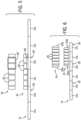
FIG. 5 is a figure similar to that ofFigs. 3 and 4 wherein the pick-up coil on the mover is displaced to one end of the magnets to overlap only a single energy transfer coil on the track at a time; and -
FIG. 6 is a figure similar to that ofFIGS. 3-4 showing pick-up coils on the mover displaced to the longitudinal ends of the movers to provide two paths of power conduction with independent energy transfer coils on the track, - In describing the various embodiments of the invention which are illustrated in the drawings, specific terminology will be resorted to for the sake of clarity. However, it is not intended that the invention be limited to the specific terms so selected and it is understood that each specific term includes all technical equivalents which operate in a similar manner to accomplish a similar purpose. For example, the word "connected," "attached," or terms similar thereto are often used. They are not limited to direct connection but include connection through other elements where such connection is recognized as being equivalent by those skilled in the art.
- The various features and advantageous details of the subject matter disclosed herein are explained more fully with reference to the non-limiting embodiments described in detail in the following description.
- The present invention recognizes the fact that the movers can span track portions having no driver coils so long as a portion of the mover's drive member engages some coils on other track portions to be held or moved by those drive coils. Accordingly, wireless transfer coils can be optionally provided on track sections between track sections holding such drive coils to allow wireless energy transfer to be provided while still employing standardized driving coil sections. Significantly, the wireless transfer can be provided in line with the track minimizing the track width such as could otherwise interfere with the associated process or manufacturing.
- Referring now to
Fig. 1 , an independent cart technology (ICT)system 10 may provide a set oftrack segments 12a-12c including, for example, a first twosegments third track segment 12b as may be assembled in, one example, into aunified track 14, being part of a larger track system, for example, including loop switches and the like. In this regard thetrack segments 12 may provide for releasable mechanical fasteners such as bolts and the like and electrical connectors so that thetrack segments 12 provide modular elements that can be readily reconfigured. Generally this pattern ofsegments segment 12b may be continued throughout thetrack 14. - A set of movers 16 (only one shown for clarity) may be positioned on the
track 14 to move there along, for example, as supported byrollers 22 held within aguide channel 24 of thetrack segment 12 so that themover 16 is constrained laterally to stay on thetrack 14, for example, by retainingwall 23 of theguide channel 24. - Each of the
track segments electromagnetic driver coils 18 spaced along an extent of thetrack segment 12 interacting with a drive member being in one examplepermanent magnets 20 within themover 16. Together the driver coils 18 andmagnets 20 provide a linear motor so that themovers 16 may be moved or positioned by the selected energization of thedriver coils 18. Thepermanent magnets 20 in themover 16 may alternate and rotate in polarity to form a so-called Halbach array to better interact with the magnetic fields generated by thedriver coils 18 which generally provide upwardly (as depicted) magnetic axes. For convenience, the invention will be discussed with respect to drivemagnets 20 being used as the drive member within eachmover 16. However, it is understood that the other magnetically salient structures such as electromagnets, electrical coils of conductive material, and ferromagnetic materials may be employed together with or replacing themagnets 20 without deviating from the scope of the invention. - In addition, each
track segment 12 may includemultiple sensors 25, for example, Hall effect sensors, magneto-diodes, an anisotropic magnetoresistive (AMR) device, fluxgate sensor, or other similar devices operating to generate an electrical signal corresponding to the presence of amover 16, for example, sensing a magnetic field of themagnets 20. Thesensors 25 allow the position of themover 16 to be determined to provide for feedback control of the motion and positioning of themovers 16. - Each
track segment track controller 26 providing a set ofelectrical switches 28 for controlling the current to the driver coils 18 according to a desired sequencing of current through those driver coils 18 for moving or positioning themover 16. As mentioned above, this sequencing may make use of the position information from thesensors 25 in a feedback loop and may implement precise motion profiles and collision detection under local control of thetrack controller 26. Theelectrical switches 28 may be solid-state switches, including, but not limited to, transistors, thyristors, or silicon-controlled rectifiers. - In order to properly sequence the
switches 28 to move or position themover 16, thetrack controller 26 may provide anelectronic processor 32, for example, having one or more processing elements communicating with interface circuitry (not shown) providing signals to theswitches 28 and receiving signals from thesensors 25 according to anoperating program 36 and data files 38 held inelectronic memory 34 and as will be further discussed below. Multiple track controllers (e.g., 26, 26') associated withdifferent segments data bus 40, for example, ethernet, for the transmission of electronic data as will also be discussed in greater detail below. - The
data bus 40 also connects thetrack controllers 26 with acentral controller 42, for example, having one ormore processors 44 communicating with anelectronic memory 46 holding an operating program andapplication program 48 as well as various data files 50 for the configuration and supervision of theICT system 10. Thecentral controller 42 may also communicate with a user terminal 52 (for example, including a graphics display for output and a keyboard, mouse, or the like for input) to allow a programming and configuration of theICT system 10 including, for example, development of theapplication program 48 dynamically defining the various destinations and starting points of themover 16. In addition, thecentral controller 42 may receive position information from thesensors 25 as relayed by thetrack controllers 26 to monitor mover traffic and may provide programming rules and motion profiles to thetrack controllers 26 as will be discussed. In some embodiments, thecentral controller 42 may be a programmable logic controller (PLC) configured to also control other machines and devices associated with the manufacturing line employing theICT system 10. This additional control may be conducted through I/O lines 47, for example, controlling actuators such as pneumatic or magnetic actuators, or motors and/or receiving additional sensor signals, for example, from limit switches, cameras, temperature monitors, and the like. - Elements of the above described independent cart technology suitable for use with the present invention are commercially available from Rockwell Automation, Inc. having offices throughout the world, for example, under the trade names of MagneMover and QuickStick, and are described in multiple US and international patents assigned to the assignee of the present application and hereby incorporated by reference including
US patent applications 2021/0213984 ; and2020/0379439 ; andUS patents 10,985,685 11,190,086 - Referring still to
Fig. 1 ,track segment 12b will not include the driver coils 18 or theswitches 28 associated with thetrack controllers 26 oftrack segments bus 40 to receive information and transmit data on thebus 40 associated withsensors 25 on thetrack segment 12b being identical in function and layout to thesensors 25 ontrack segments - Instead of the driver coils 18, the
track segment 12b will include one or more energy transfer coils 30 for wireless transfer of power to a pick-upcoil 60 on themover 16. Generally, the elimination of the driver coils 18 intrack segment 12b and their associated circuitry in favor of the energy transfer coil 30 (and its associated circuitry) allows thistrack segment 12 to be lower in cost thantrack segments power transmission coil 30 in thetrack segment 12b. Placing thepower transmission coil 30 in this track also allows wireless energy transfer to be optionally added to anytrack 14 allowing better tailoring of the system to individual applications. This versatility is important because theICT system 10 will be used in a variety of manufacturing applications only some of which will require wireless power transfer. - Referring still to
Fig.1 , thesensors 25 on thetrack segment 12b allow the track controller 26' to sense and relay the position of themovers 16 as they passes overtrack segment 12b toadjacent track controllers 26 for seamless motion control (e.g., acceleration, deceleration and stopping) of themovers 16 as they cross betweentrack segments 12 and further allows the activation of theenergy transfer coil 30 only whenmovers 16 are present ontrack segment 12b for energy conservation. - The length of
track segment 12b with respect to the length of the drive member (e.g., magnets 20) of themover 16 will be set such that the drive member of themover 16 is always engaged withdriver coils 18 of one or both of thetrack segments mover 16 may be implemented. Also, in this regard, the pitch spatial phasing of the driver coils 18 in each oftrack segments track segment 12b) is set to match so that themover 16 may electromagnetically engage with one or both of thetrack segments track segment 12b. In one embodiment, the length of thetrack segment 12b will be equal to an integer number ofspacings 31 of the driver coils 18 ontrack segment spacings 31 equal to the number of driver coils 18 forming a pole of the resultant linear motor. - Referring now to
Fig. 2 , and as noted above, generally themover 16 will include not only the drive member such asmagnets 20 but a pick-upcoil 60 typically having an axis (vertically as shown) parallel to the axis of theenergy transfer coil 30. According to one aspect of the invention, the pick-upcoil 60 and/or thecoils 30 may be wound from a solid conductor or from Litz wire or maybe formed from a number of traces on one or more layers of a printed circuit board (PCB). - In this regard, the track controller 26' may include a drive circuit 64 providing power to the
coil 30, for example, a sine wave AC signal per aninternal oscillator 66 as amplified byamplifier 68. The operation of the drive circuit 64 may be controlled by signals over thedata bus 40 to deactivate this circuit when amover 16 is not present ontrack segment 12b. Generally theoscillator 66 will operate at a high frequency in excess of 10 kHz and typically in excess of 100 kHz. - The drive circuit 64 may be connected to the
coil 30 throughcapacitor 70 to provide a series resonance with the inductance of thecoil 30 at the frequency of theoscillator 66 for maximum energy transfer. - The track controller 26' (and each of the track controllers 26) may also receive sensor signals from a second redundant set of sensors 25' as required by some types of application (e.g., SIL standards). The signals from these two sets of
sensors 25 and 25' are compared by thecentral controller 42 to detect sensor failure and to move the system to a safety state, for example, by stopping the movers 1 6. - The pick-up
coil 60 similarly connects to anenergy extraction circuit 74 on themover 16 and may receive an electrical signal from the pick-upcoil 60 throughcapacitor 75 providing a series resonant circuit with the inductance of pick-upcoil 60 to the same frequency of the drive circuit 64 provided byoscillator 66. In this way the pick-upcoil 60 may receive power wirelessly from thetrack segment 12b. - The
energy extraction circuit 74 may include apower converter 76 configured to receive the AC voltage induced on the pick-upcoil 60 as an input and to provide a second voltage as an output. The power converter may include, for example, diodes arranged as a passive full-wave rectifier to convert the AC voltage to a DC voltage. Thepower converter 76 may also include an output capacitance (not shown) in order to reduce a ripple present on the DC voltage from rectification. Alternatively or in addition, thepower converter 76 may include or be made up entirely by a voltage regulator operating directly on an AC signal or configured to receive the rectified DC voltage or the AC voltage induced in the pick-upcoil 60 as an input and supply one or more constant DC voltages for use by other devices on theenergy extraction circuit 74. - The
energy extraction circuit 74 may further include anenergy storage device 78, such as a storage capacitor or battery to store energy received at the pick-upcoil 60. During periods of time when the energy received via the pick-upcoil 60 exceeds the energy required by the electronic devices on theenergy extraction circuit 74, thepower converter 76 may supply energy to theenergy storage device 78. During periods of time when the energy received via the pick-upcoil 60 is less than the energy required by the electronic devices on theenergy extraction circuit 74, thepower converter 76 may draw stored energy from theenergy storage device 78. - It is contemplated that the energy received by the pick-up coil may be used to energize at least one power-consuming
device 80 mounted on themover 16. The power-consumingdevice 80 may be part of circuitenergy extraction circuit 74, external from the circuitenergy extraction circuit 74, or a combination thereof. The power-consumingdevice 80 will be selected according to the application requirements but may include, for example, an indicator providing a status of operation on themover 16, an actuator interacting with a product on the mover, a sensor providing a status, such as the presence or absence, of a product on the mover, and the like. Sensors may be provided that, for example, detect vibration or temperature on themover 16. The energy harvested by the pick-upcoil 60 may provide for advanced analytics, condition monitoring, or safety applications to be incorporated in the linear drive system as a result of the wireless energy transfer between the energy transfer coils 30 and the pick-upcoil 60. - It is further contemplated that a
control circuit 82 may be required to control operation of the power-consumingdevice 80. Thecontrol circuit 82 may be a series of discrete logic devices implementing combinatorial logic, a processor operative to execute instructions stored in memory, or a combination thereof. Thecontrol circuit 82 may receive one or more inputs corresponding to an operating status of the mover, a product on the mover, or of the controlled process with which the mover is interacting and may generate one or more outputs to an actuator to achieve a desired performance in response to the inputs. - The power-consuming device(s) 80 may further include a wireless transmitter or transceiver operative to transmit information from the
control circuit 82 to a receiver or second transceiver mounted on thetrack segment 12b, adjacent to the track, in the systemcentral controller 42, or to any other suitable location according to the application requirements. The transmitter may communicate via a radio frequency (RF) signal, infrared signal, or via any other wireless communication medium as would be understood in the art. - In the following embodiments, the size of the pick-up
coil 60 will be adjusted to provide good flux coupling with thecoil 30 throughout the range of travel and generally, for this purpose, the length along thetrack segment 12b of the one of the pick-upcoil 60 andcoil 30 may be much longer than the other of thecoil 30 and pick-up coil 60 (for example, at least twice as long as the shorter coil) to provide a more constant and continuous coupling as themover 16 moves over at least one portion of the atrack segment 12. - Referring now to
Fig. 3 , in a first embodiment, the pick-upcoil 60 on themover 16 may be wrapped around the outer periphery of the magnets 20 (or the other drive member) to provide a length along thetrack 14 that spans multiple energy transfer coils 30 so that there is always oneenergy transfer coil 30 electrically coupling with the pick-upcoil 60 to provide energy transfer thereto. In this embodiment, it is beneficial that the phase of the signals in energy transfer coils 30 be identical such as may be accomplished by means of a timing signal communicating synchronization signals through thedata bus 40 betweenoscillators 66, for example, using a phase locked loop or the like. - Referring now to
Fig. 4 , in an alternative embodiment, the pick-upcoil 60 may overlap in a vertical direction with themagnets 20 which may serve to concentrate flux from the energy transfer coils 30 into the pick-upcoil 60 by providing a high permeability backing material. Thetrack 14 may otherwise be identical to that described above with respect toFig. 3 . - Referring now to
Fig. 5 , in a third embodiment, the pick-upcoil 60 may be displaced with respect to themagnets 20 on themover 16 to one longitudinal end of themover 16. In addition or alternatively, the length of the pick-upcoil 60 may be reduced so as to overlap at any given time with only a singleenergy transfer coil 30 on thetrack 14. In this way, phasing of theoscillators 66 ofdifferent track segments 12b need not be identical, simplifying their construction. Interruption of power when the energy transfer coils 30 and pick-upcoil 60 are not aligned may be accommodated through theenergy storage devices 78 ofFig. 2 or by increasing the longitudinal length of the pick-upcoil 60 by an amount just less than the total length oftrack segments 12a (or 12c) and 12b. - Referring to
Fig. 6 , the ability to avoid the need to match the phase is of theoscillators 66 while providing continuous or near continuous power may be provided by using two pick-upcoils 60 and displacing them from each other, for example, to the longitudinal ends of themagnets 20 to provide a first and second independent pick-upcoil 60 that may simultaneously or individually provide power coupling. It will be appreciated by appropriate extension of the length of the pick-upcoil 60 this power coupling can be continuous. In this case, the power from pick-upcoils power converter 76 so that DC signals are combined, the DC signals being phase indifferent. - It should be understood that the invention is not limited in its application to the details of construction and arrangements of the components set forth herein. The invention is capable of other embodiments and of being practiced or carried out in various ways. Variations and modifications of the foregoing are within the scope of the present invention. It also being understood that the invention disclosed and defined herein extends to all alternative combinations of two or more of the individual features mentioned or evident from the text and/or drawings. All of these different combinations constitute various alternative aspects of the present invention. The embodiments described herein explain the best modes known for practicing the invention and will enable others skilled in the art to utilize the invention.
- Embodiment 1. An apparatus for wireless energy transfer in an independent cart system, the apparatus comprising:
- a track assembly having a first, second, and third portion with the first and second portions providing drive coils mounted along the length of the track and flanking the second portion devoid of drive coils, the second portion providing an energy transfer coil;
- a plurality of movers operative to travel along the track, each of the plurality of movers comprising:
- a drive member, and
- a pick-up coil mounted for electrical interaction with the energy transfer coil when a given mover is aligned with a given second track portion;
- wherein the first and second track portions include respective current drive circuits providing current to respective drive coils to generate electromagnetic fields which engages mover drive members to propel each movers along the track, and
- wherein the second track portion includes an energy transfer circuit providing current to the energy transfer coil to transfer electrical energy through mutual inductance to pick-up coils of the movers.
- Embodiment 2. The apparatus of embodiment 1 wherein the first, second, and third track portions provide laterally opposed mover support surfaces perpendicular to a motion of the movers and engaging rollers on the movers and wherein the drive coils and energy transfer coils are positioned between lateral support surfaces.
- Embodiment 3. The apparatus of embodiment 1 wherein the first, second, and third track portions provide releasable interconnections for attaching and releasing the track portions to other track portions.
- Embodiment 4. The apparatus of embodiment 1 wherein the first, second, and third track portions further include mover position sensors detecting a position of the movers on the track portions.
- Embodiment 5. The apparatus of embodiment 1 wherein the first, second, and third track portions further include a first and second redundant set of mover sensors each detecting a position of the movers on the track portion to provide two independent mover position signals for a given mover.
- Embodiment 6. The apparatus of embodiment 1 wherein the energy transfer coil and pick-up coils differ in extent along a length of the track by at least two times a length of the shorter coil.
- Embodiment 7. The apparatus of embodiment 1 wherein the energy transfer coil and pick-up coil align to provide energy transfer only when a mover is over a portion of a given track less than the length of the given track.
- Embodiment 8. The apparatus of embodiment 1 wherein the drive assembly is a magnet array and the pick-up coil extends a length of the magnet array measured along a direction of mover motion.
- Embodiment 9. The apparatus of embodiment 1 wherein pick-up coil is displaced along the track away from the drive member to an end of the drive member.
-
Embodiment 10. The apparatus of embodiment 1 wherein movers include a first and second pick-up coil mounted for mutually exclusive electrical interaction with a given energy transmission coil. - Embodiment 11. A method of wireless energy transfer in an independent cart system, comprising:
- providing a track having a first, second, and third portion with the first and second portions providing drive coils mounted along the length of the track and flanking the second portion devoid of drive coils, the second portion providing an energy transfer coil;
- populating the track with a plurality of movers operative to travel along the track, each of the plurality of movers having a drive member and a pick-up coil mounted for electrical interaction with the energy transfer coil when a given mover is aligned with a given second track portion;
- applying current to the drive coils to generate electromagnetic fields which engages mover drive members to propel each mover along the track, and
- applying current to the energy transfer coil to transfer electrical energy through mutual inductance to pick-up coils of the movers.
-
Embodiment 12. The method of embodiment 11 wherein the first, second, and third track portions provide laterally opposed mover support surfaces perpendicular to a motion of the movers and engaging rollers on the movers and wherein the drive coils and energy transfer coils are positioned between lateral support surfaces. - Embodiment 13. The method of embodiment 11 wherein the first, second, and third track portions provide releasable interconnections for attaching and releasing the track portions to other track portions.
-
Embodiment 14. The method of embodiment 11 wherein the first, second, and third track portions further include mover position sensors detecting a position of the movers on the track portions and including a sensing of the movers as they move over the track portions and control the drive coils according to the sensing. - Embodiment 15. The method of embodiment 11 wherein the first, second, and third track portions further include a first and second redundant set of mover sensors each detecting a position of the movers on the track portion to provide two independent mover position signals for a given mover and including comparing the independent mover position signals to detect a sensor failure.
-
Embodiment 16. The method of embodiment 11 wherein the energy transfer coil and pick-up coils differ in extent along a length of the track by at least two times a length of the shorter coil. - Embodiment 17. The method of embodiment 11 wherein the energy transfer coil and pick-up coil align to provide energy transfer only when a mover is over a portion of a given track less than the length of the given track.
-
Embodiment 18. The method of embodiment 11 wherein the drive assembly is a magnet array and the pick-up coil extends a length of the magnet array measured along a direction of mover motion. - Embodiment 19. The method of embodiment 11 wherein a pick-up coil is displaced along the track away from the drive member to an end of the drive member.
-
Embodiment 20. An apparatus for wireless energy transfer in an independent cart system, the apparatus comprising: - a track assembly having a track providing drive coils mounted along the length of the track at a given periodicity, the drive coils extending laterally to define a drive coil width across the track with respect to the track and a gap portion along the track greater in length than the given periodicity and free from drive coils, the gap portion holding an energy transfer coil within the drive coil width;
- a plurality of movers operative to travel along the track, each of the plurality of movers comprising:
- a drive member, and
- a pick-up coil mounted for electrical interaction with the energy transfer coil during movement over the track;
- wherein track include respective drive circuits providing current to respective drive coils to generate electromagnetic fields which engages mover drive members to propel each movers along the track, and energy transfer circuits providing current to the energy transfer coil to transfer electrical energy through mutual inductance to pick-up coils of the movers.
Claims (15)
- An apparatus for wireless energy transfer in an independent cart system, the apparatus comprising:a track assembly having a first, second, and third portion with the first and second portions providing drive coils mounted along the length of the track and flanking the second portion devoid of drive coils, the second portion providing an energy transfer coil;a plurality of movers operative to travel along the track, each of the plurality of movers comprising:a drive member, anda pick-up coil mounted for electrical interaction with the energy transfer coil when a given mover is aligned with a given second track portion;wherein the first and second track portions include respective current drive circuits providing current to respective drive coils to generate electromagnetic fields which engages mover drive members to propel each movers along the track, andwherein the second track portion includes an energy transfer circuit providing current to the energy transfer coil to transfer electrical energy through mutual inductance to pick-up coils of the movers.
- The apparatus of claim 1 wherein the first, second, and third track portions provide laterally opposed mover support surfaces perpendicular to a motion of the movers and engaging rollers on the movers and wherein the drive coils and energy transfer coils are positioned between lateral support surfaces.
- The apparatus of claim 1 or 2 wherein the first, second, and third track portions provide releasable interconnections for attaching and releasing the track portions to other track portions; or
wherein the first, second, and third track portions further include mover position sensors detecting a position of the movers on the track portions. - The apparatus of one of claims 1 to 3 wherein the first, second, and third track portions further include a first and second redundant set of mover sensors each detecting a position of the movers on the track portion to provide two independent mover position signals for a given mover.
- The apparatus of one of claims 1 to 4 wherein the energy transfer coil and pick-up coils differ in extent along a length of the track by at least two times a length of the shorter coil; or
wherein the energy transfer coil and pick-up coil align to provide energy transfer only when a mover is over a portion of a given track less than the length of the given track. - The apparatus of one of claims 1 to 5 wherein the drive assembly is a magnet array and the pick-up coil extends a length of the magnet array measured along a direction of mover motion.
- The apparatus of one of claims 1 to 6 wherein pick-up coil is displaced along the track away from the drive member to an end of the drive member.
- The apparatus of one of claims 1 to 7 wherein movers include a first and second pick-up coil mounted for mutually exclusive electrical interaction with a given energy transmission coil.
- A method of wireless energy transfer in an independent cart system, comprising:providing a track having a first, second, and third portion with the first and second portions providing drive coils mounted along the length of the track and flanking the second portion devoid of drive coils, the second portion providing an energy transfer coil;populating the track with a plurality of movers operative to travel along the track, each of the plurality of movers having a drive member and a pick-up coil mounted for electrical interaction with the energy transfer coil when a given mover is aligned with a given second track portion;applying current to the drive coils to generate electromagnetic fields which engages mover drive members to propel each mover along the track, andapplying current to the energy transfer coil to transfer electrical energy through mutual inductance to pick-up coils of the movers.
- The method of claim 9 wherein the first, second, and third track portions provide laterally opposed mover support surfaces perpendicular to a motion of the movers and engaging rollers on the movers and wherein the drive coils and energy transfer coils are positioned between lateral support surfaces.
- The method of claim 9 or 10 wherein the first, second, and third track portions provide releasable interconnections for attaching and releasing the track portions to other track portions; or
wherein the first, second, and third track portions further include mover position sensors detecting a position of the movers on the track portions and including a sensing of the movers as they move over the track portions and control the drive coils according to the sensing. - The method of one of claims 9 to 11 wherein the first, second, and third track portions further include a first and second redundant set of mover sensors each detecting a position of the movers on the track portion to provide two independent mover position signals for a given mover and including comparing the independent mover position signals to detect a sensor failure.
- The method of one of claims 9 to 12 wherein the energy transfer coil and pick-up coils differ in extent along a length of the track by at least two times a length of the shorter coil; or wherein the energy transfer coil and pick-up coil align to provide energy transfer only when a mover is over a portion of a given track less than the length of the given track.
- The method of one of claims 9 to 13 wherein the drive assembly is a magnet array and the pick-up coil extends a length of the magnet array measured along a direction of mover motion; or
wherein a pick-up coil is displaced along the track away from the drive member to an end of the drive member. - An apparatus for wireless energy transfer in an independent cart system, the apparatus comprising:a track assembly having a track providing drive coils mounted along the length of the track at a given periodicity, the drive coils extending laterally to define a drive coil width across the track with respect to the track and a gap portion along the track greater in length than the given periodicity and free from drive coils, the gap portion holding an energy transfer coil within the drive coil width;a plurality of movers operative to travel along the track, each of the plurality of movers comprising:a drive member, anda pick-up coil mounted for electrical interaction with the energy transfer coil during movement over the track;wherein track include respective drive circuits providing current to respective drive coils to generate electromagnetic fields which engages mover drive members to propel each movers along the track, and energy transfer circuits providing current to the energy transfer coil to transfer electrical energy through mutual inductance to pick-up coils of the movers.
Applications Claiming Priority (1)
| Application Number | Priority Date | Filing Date | Title |
|---|---|---|---|
| US17/889,018 US11831182B1 (en) | 2022-08-16 | 2022-08-16 | System and method for in-line wireless energy transfer and sensing in an independent cart system |
Publications (1)
| Publication Number | Publication Date |
|---|---|
| EP4335682A2 true EP4335682A2 (en) | 2024-03-13 |
Family
ID=87074713
Family Applications (1)
| Application Number | Title | Priority Date | Filing Date |
|---|---|---|---|
| EP23183114.0A Pending EP4335682A2 (en) | 2022-08-16 | 2023-07-03 | System and method for in-line wireless energy transfer and sensing in an independent cart system |
Country Status (3)
| Country | Link |
|---|---|
| US (1) | US11831182B1 (en) |
| EP (1) | EP4335682A2 (en) |
| CN (1) | CN117595524A (en) |
Families Citing this family (1)
| Publication number | Priority date | Publication date | Assignee | Title |
|---|---|---|---|---|
| US20240109735A1 (en) * | 2022-09-29 | 2024-04-04 | Rockwell Automation Technologies, Inc. | System and Method for Achieving Position Detection Integrity in an Independent Cart System |
Citations (4)
| Publication number | Priority date | Publication date | Assignee | Title |
|---|---|---|---|---|
| US20200379439A1 (en) | 2019-05-31 | 2020-12-03 | Rockwell Automation Technologies, Inc | Automated Independent Cart System and Method of Controlling Operation of a Plurality of movers of the Automated Independent Cart System |
| US10985685B1 (en) | 2019-09-30 | 2021-04-20 | Rockwell Automation Technologies, Inc. | System and method for wireless power transfer in a linear cart system |
| US20210213984A1 (en) | 2018-11-08 | 2021-07-15 | Rockwell Automation Technologies, Inc. | Independent Cart System And Method Of Operating The Same |
| US11190086B2 (en) | 2018-11-13 | 2021-11-30 | Rockwell Automation Technologies, Inc. | Track connection module for linear motor tracks |
Family Cites Families (4)
| Publication number | Priority date | Publication date | Assignee | Title |
|---|---|---|---|---|
| EP1270311B1 (en) * | 1997-05-02 | 2005-09-14 | Ats Automation Tooling Systems Inc. | Modular conveyor system having multiple moving elements under independent control |
| JP5648722B1 (en) * | 2013-08-02 | 2015-01-07 | 株式会社安川電機 | Linear motor system |
| DE102018111715A1 (en) | 2018-05-16 | 2019-11-21 | Beckhoff Automation Gmbh | LINEAR TRANSPORT SYSTEM AND SYSTEM FOR CONTACTLESS ENERGY AND DATA TRANSMISSION |
| EP3960668A1 (en) * | 2020-08-28 | 2022-03-02 | Schneider Electric Industries SAS | Linear motor system and method for operating same |
-
2022
- 2022-08-16 US US17/889,018 patent/US11831182B1/en active Active
-
2023
- 2023-07-03 EP EP23183114.0A patent/EP4335682A2/en active Pending
- 2023-07-12 CN CN202310855900.3A patent/CN117595524A/en active Pending
Patent Citations (4)
| Publication number | Priority date | Publication date | Assignee | Title |
|---|---|---|---|---|
| US20210213984A1 (en) | 2018-11-08 | 2021-07-15 | Rockwell Automation Technologies, Inc. | Independent Cart System And Method Of Operating The Same |
| US11190086B2 (en) | 2018-11-13 | 2021-11-30 | Rockwell Automation Technologies, Inc. | Track connection module for linear motor tracks |
| US20200379439A1 (en) | 2019-05-31 | 2020-12-03 | Rockwell Automation Technologies, Inc | Automated Independent Cart System and Method of Controlling Operation of a Plurality of movers of the Automated Independent Cart System |
| US10985685B1 (en) | 2019-09-30 | 2021-04-20 | Rockwell Automation Technologies, Inc. | System and method for wireless power transfer in a linear cart system |
Also Published As
| Publication number | Publication date |
|---|---|
| US11831182B1 (en) | 2023-11-28 |
| CN117595524A (en) | 2024-02-23 |
Similar Documents
| Publication | Publication Date | Title |
|---|---|---|
| US11581838B2 (en) | System and method for wireless power transfer in a linear cart system | |
| US11715977B2 (en) | Method and system for contactless power transfer in a linear drive system | |
| EP4335682A2 (en) | System and method for in-line wireless energy transfer and sensing in an independent cart system | |
| US11303242B2 (en) | Method and apparatus for wireless power transfer to an independent moving cart | |
| CN106132864B (en) | System and method for determining the magnetic field orientating of magnetic part in cordless elevator system | |
| KR20140098062A (en) | System and method for providing vacuum to a moving element | |
| JP2007500495A (en) | Linear motor with movement adjustment function | |
| JP7137300B2 (en) | Conveying device, conveying system, conveying system control method, processing system, and article manufacturing method | |
| CN101009455A (en) | Long range big-push force permanent-magnet brushless linear DC motor | |
| JP4427544B2 (en) | Contactless energy supply for moving loads | |
| WO2010107806A1 (en) | Conveyor belt apparatus and method including magnetically actuated rollers | |
| KR20170024562A (en) | Elevator wireless power transfer system | |
| CN112385116A (en) | Linear transport system and contactless power and data transmission system | |
| CN107206916B (en) | Movable power coupling and robot with movable power coupling | |
| EP3653552A1 (en) | Track connection module for linear motor tracks | |
| US11539244B2 (en) | Method and apparatus for data transmission over an inductive link for an independent cart system | |
| WO2019043795A1 (en) | Power transmission unit, transport conveyor, and coil holding part | |
| WO2020073118A1 (en) | Systems and methods for identifying a magnetic mover | |
| JP2003070225A (en) | Path module for linear motor, modular linear motor system, and controlling method therefor | |
| CN115668688A (en) | Self-powered sensor unit for food packaging machines | |
| US20230356599A1 (en) | Contactless electrical power transfer and motive device therewith | |
| US20240067238A1 (en) | System and Method for Mounting Fixtures on an Independent Cart | |
| KR20240051048A (en) | Contactless power feeding facility | |
| JP2024057317A (en) | Non-contact power supply equipment | |
| CN117879182A (en) | Contactless power supply device |
Legal Events
| Date | Code | Title | Description |
|---|---|---|---|
| PUAI | Public reference made under article 153(3) epc to a published international application that has entered the european phase |
Free format text: ORIGINAL CODE: 0009012 |
|
| STAA | Information on the status of an ep patent application or granted ep patent |
Free format text: STATUS: THE APPLICATION HAS BEEN PUBLISHED |
|
| AK | Designated contracting states |
Kind code of ref document: A2 Designated state(s): AL AT BE BG CH CY CZ DE DK EE ES FI FR GB GR HR HU IE IS IT LI LT LU LV MC ME MK MT NL NO PL PT RO RS SE SI SK SM TR |