EP4335616A1 - Method and device for reforming plastic preforms into plastic containers with intermediate blow pressure control - Google Patents
Method and device for reforming plastic preforms into plastic containers with intermediate blow pressure control Download PDFInfo
- Publication number
- EP4335616A1 EP4335616A1 EP23194549.4A EP23194549A EP4335616A1 EP 4335616 A1 EP4335616 A1 EP 4335616A1 EP 23194549 A EP23194549 A EP 23194549A EP 4335616 A1 EP4335616 A1 EP 4335616A1
- Authority
- EP
- European Patent Office
- Prior art keywords
- pressure
- pressure level
- operating mode
- reservoir
- plastic preforms
- Prior art date
- Legal status (The legal status is an assumption and is not a legal conclusion. Google has not performed a legal analysis and makes no representation as to the accuracy of the status listed.)
- Pending
Links
- 238000000034 method Methods 0.000 title claims abstract description 32
- 238000002407 reforming Methods 0.000 title 1
- 230000032258 transport Effects 0.000 claims abstract description 30
- 230000009969 flowable effect Effects 0.000 claims abstract description 11
- 230000007704 transition Effects 0.000 claims description 5
- 238000007664 blowing Methods 0.000 description 63
- 238000004064 recycling Methods 0.000 description 12
- 230000008569 process Effects 0.000 description 8
- 238000011084 recovery Methods 0.000 description 4
- 230000008901 benefit Effects 0.000 description 3
- 238000000071 blow moulding Methods 0.000 description 3
- 238000004519 manufacturing process Methods 0.000 description 3
- 238000007639 printing Methods 0.000 description 3
- 230000008859 change Effects 0.000 description 2
- 239000003638 chemical reducing agent Substances 0.000 description 2
- 238000011161 development Methods 0.000 description 2
- 230000018109 developmental process Effects 0.000 description 2
- 238000009826 distribution Methods 0.000 description 2
- 238000006243 chemical reaction Methods 0.000 description 1
- 230000001276 controlling effect Effects 0.000 description 1
- 238000001514 detection method Methods 0.000 description 1
- 238000000605 extraction Methods 0.000 description 1
- 238000007689 inspection Methods 0.000 description 1
- 230000001105 regulatory effect Effects 0.000 description 1
- 230000004044 response Effects 0.000 description 1
- 238000007789 sealing Methods 0.000 description 1
- 238000003860 storage Methods 0.000 description 1
- 230000001360 synchronised effect Effects 0.000 description 1
- 230000001960 triggered effect Effects 0.000 description 1
- XLYOFNOQVPJJNP-UHFFFAOYSA-N water Substances O XLYOFNOQVPJJNP-UHFFFAOYSA-N 0.000 description 1
Images


Classifications
-
- B—PERFORMING OPERATIONS; TRANSPORTING
- B29—WORKING OF PLASTICS; WORKING OF SUBSTANCES IN A PLASTIC STATE IN GENERAL
- B29C—SHAPING OR JOINING OF PLASTICS; SHAPING OF MATERIAL IN A PLASTIC STATE, NOT OTHERWISE PROVIDED FOR; AFTER-TREATMENT OF THE SHAPED PRODUCTS, e.g. REPAIRING
- B29C49/00—Blow-moulding, i.e. blowing a preform or parison to a desired shape within a mould; Apparatus therefor
- B29C49/42—Component parts, details or accessories; Auxiliary operations
- B29C49/4284—Means for recycling or reusing auxiliaries or materials, e.g. blowing fluids or energy
- B29C49/42845—Recycling or reusing of fluid, e.g. pressure
-
- B—PERFORMING OPERATIONS; TRANSPORTING
- B29—WORKING OF PLASTICS; WORKING OF SUBSTANCES IN A PLASTIC STATE IN GENERAL
- B29C—SHAPING OR JOINING OF PLASTICS; SHAPING OF MATERIAL IN A PLASTIC STATE, NOT OTHERWISE PROVIDED FOR; AFTER-TREATMENT OF THE SHAPED PRODUCTS, e.g. REPAIRING
- B29C49/00—Blow-moulding, i.e. blowing a preform or parison to a desired shape within a mould; Apparatus therefor
- B29C49/0031—Making articles having hollow walls
-
- B—PERFORMING OPERATIONS; TRANSPORTING
- B29—WORKING OF PLASTICS; WORKING OF SUBSTANCES IN A PLASTIC STATE IN GENERAL
- B29C—SHAPING OR JOINING OF PLASTICS; SHAPING OF MATERIAL IN A PLASTIC STATE, NOT OTHERWISE PROVIDED FOR; AFTER-TREATMENT OF THE SHAPED PRODUCTS, e.g. REPAIRING
- B29C49/00—Blow-moulding, i.e. blowing a preform or parison to a desired shape within a mould; Apparatus therefor
- B29C49/006—Blow-moulding plants, e.g. using several blow-moulding apparatuses cooperating
- B29C49/0062—Blow-moulding plants, e.g. using several blow-moulding apparatuses cooperating using two or more parallel stations, e.g. two parallel heating or blowing stations
-
- B—PERFORMING OPERATIONS; TRANSPORTING
- B29—WORKING OF PLASTICS; WORKING OF SUBSTANCES IN A PLASTIC STATE IN GENERAL
- B29C—SHAPING OR JOINING OF PLASTICS; SHAPING OF MATERIAL IN A PLASTIC STATE, NOT OTHERWISE PROVIDED FOR; AFTER-TREATMENT OF THE SHAPED PRODUCTS, e.g. REPAIRING
- B29C49/00—Blow-moulding, i.e. blowing a preform or parison to a desired shape within a mould; Apparatus therefor
- B29C49/28—Blow-moulding apparatus
-
- B—PERFORMING OPERATIONS; TRANSPORTING
- B29—WORKING OF PLASTICS; WORKING OF SUBSTANCES IN A PLASTIC STATE IN GENERAL
- B29C—SHAPING OR JOINING OF PLASTICS; SHAPING OF MATERIAL IN A PLASTIC STATE, NOT OTHERWISE PROVIDED FOR; AFTER-TREATMENT OF THE SHAPED PRODUCTS, e.g. REPAIRING
- B29C49/00—Blow-moulding, i.e. blowing a preform or parison to a desired shape within a mould; Apparatus therefor
- B29C49/42—Component parts, details or accessories; Auxiliary operations
- B29C49/4205—Handling means, e.g. transfer, loading or discharging means
- B29C49/42093—Transporting apparatus, e.g. slides, wheels or conveyors
- B29C49/42095—Rotating wheels or stars
-
- B—PERFORMING OPERATIONS; TRANSPORTING
- B29—WORKING OF PLASTICS; WORKING OF SUBSTANCES IN A PLASTIC STATE IN GENERAL
- B29C—SHAPING OR JOINING OF PLASTICS; SHAPING OF MATERIAL IN A PLASTIC STATE, NOT OTHERWISE PROVIDED FOR; AFTER-TREATMENT OF THE SHAPED PRODUCTS, e.g. REPAIRING
- B29C49/00—Blow-moulding, i.e. blowing a preform or parison to a desired shape within a mould; Apparatus therefor
- B29C49/42—Component parts, details or accessories; Auxiliary operations
- B29C49/4273—Auxiliary operations after the blow-moulding operation not otherwise provided for
- B29C49/42815—Emptying the article, e.g. emptying hydraulic blowing fluid
-
- B—PERFORMING OPERATIONS; TRANSPORTING
- B29—WORKING OF PLASTICS; WORKING OF SUBSTANCES IN A PLASTIC STATE IN GENERAL
- B29C—SHAPING OR JOINING OF PLASTICS; SHAPING OF MATERIAL IN A PLASTIC STATE, NOT OTHERWISE PROVIDED FOR; AFTER-TREATMENT OF THE SHAPED PRODUCTS, e.g. REPAIRING
- B29C49/00—Blow-moulding, i.e. blowing a preform or parison to a desired shape within a mould; Apparatus therefor
- B29C49/42—Component parts, details or accessories; Auxiliary operations
- B29C49/78—Measuring, controlling or regulating
- B29C49/783—Measuring, controlling or regulating blowing pressure
- B29C2049/7832—Blowing with two or more pressure levels
- B29C2049/7833—Blowing with three or more pressure levels
-
- B—PERFORMING OPERATIONS; TRANSPORTING
- B29—WORKING OF PLASTICS; WORKING OF SUBSTANCES IN A PLASTIC STATE IN GENERAL
- B29C—SHAPING OR JOINING OF PLASTICS; SHAPING OF MATERIAL IN A PLASTIC STATE, NOT OTHERWISE PROVIDED FOR; AFTER-TREATMENT OF THE SHAPED PRODUCTS, e.g. REPAIRING
- B29C49/00—Blow-moulding, i.e. blowing a preform or parison to a desired shape within a mould; Apparatus therefor
- B29C49/42—Component parts, details or accessories; Auxiliary operations
- B29C49/78—Measuring, controlling or regulating
- B29C2049/788—Controller type or interface
- B29C2049/7882—Control interface, e.g. display
-
- B—PERFORMING OPERATIONS; TRANSPORTING
- B29—WORKING OF PLASTICS; WORKING OF SUBSTANCES IN A PLASTIC STATE IN GENERAL
- B29C—SHAPING OR JOINING OF PLASTICS; SHAPING OF MATERIAL IN A PLASTIC STATE, NOT OTHERWISE PROVIDED FOR; AFTER-TREATMENT OF THE SHAPED PRODUCTS, e.g. REPAIRING
- B29C2791/00—Shaping characteristics in general
- B29C2791/004—Shaping under special conditions
- B29C2791/007—Using fluid under pressure
-
- B—PERFORMING OPERATIONS; TRANSPORTING
- B29—WORKING OF PLASTICS; WORKING OF SUBSTANCES IN A PLASTIC STATE IN GENERAL
- B29C—SHAPING OR JOINING OF PLASTICS; SHAPING OF MATERIAL IN A PLASTIC STATE, NOT OTHERWISE PROVIDED FOR; AFTER-TREATMENT OF THE SHAPED PRODUCTS, e.g. REPAIRING
- B29C2949/00—Indexing scheme relating to blow-moulding
- B29C2949/07—Preforms or parisons characterised by their configuration
- B29C2949/0715—Preforms or parisons characterised by their configuration the preform having one end closed
-
- B—PERFORMING OPERATIONS; TRANSPORTING
- B29—WORKING OF PLASTICS; WORKING OF SUBSTANCES IN A PLASTIC STATE IN GENERAL
- B29C—SHAPING OR JOINING OF PLASTICS; SHAPING OF MATERIAL IN A PLASTIC STATE, NOT OTHERWISE PROVIDED FOR; AFTER-TREATMENT OF THE SHAPED PRODUCTS, e.g. REPAIRING
- B29C49/00—Blow-moulding, i.e. blowing a preform or parison to a desired shape within a mould; Apparatus therefor
- B29C49/02—Combined blow-moulding and manufacture of the preform or the parison
- B29C49/06—Injection blow-moulding
-
- B—PERFORMING OPERATIONS; TRANSPORTING
- B29—WORKING OF PLASTICS; WORKING OF SUBSTANCES IN A PLASTIC STATE IN GENERAL
- B29C—SHAPING OR JOINING OF PLASTICS; SHAPING OF MATERIAL IN A PLASTIC STATE, NOT OTHERWISE PROVIDED FOR; AFTER-TREATMENT OF THE SHAPED PRODUCTS, e.g. REPAIRING
- B29C49/00—Blow-moulding, i.e. blowing a preform or parison to a desired shape within a mould; Apparatus therefor
- B29C49/08—Biaxial stretching during blow-moulding
- B29C49/10—Biaxial stretching during blow-moulding using mechanical means for prestretching
- B29C49/12—Stretching rods
-
- B—PERFORMING OPERATIONS; TRANSPORTING
- B29—WORKING OF PLASTICS; WORKING OF SUBSTANCES IN A PLASTIC STATE IN GENERAL
- B29C—SHAPING OR JOINING OF PLASTICS; SHAPING OF MATERIAL IN A PLASTIC STATE, NOT OTHERWISE PROVIDED FOR; AFTER-TREATMENT OF THE SHAPED PRODUCTS, e.g. REPAIRING
- B29C49/00—Blow-moulding, i.e. blowing a preform or parison to a desired shape within a mould; Apparatus therefor
- B29C49/42—Component parts, details or accessories; Auxiliary operations
- B29C49/42378—Handling malfunction
-
- B—PERFORMING OPERATIONS; TRANSPORTING
- B29—WORKING OF PLASTICS; WORKING OF SUBSTANCES IN A PLASTIC STATE IN GENERAL
- B29K—INDEXING SCHEME ASSOCIATED WITH SUBCLASSES B29B, B29C OR B29D, RELATING TO MOULDING MATERIALS OR TO MATERIALS FOR MOULDS, REINFORCEMENTS, FILLERS OR PREFORMED PARTS, e.g. INSERTS
- B29K2067/00—Use of polyesters or derivatives thereof, as moulding material
- B29K2067/003—PET, i.e. poylethylene terephthalate
-
- B—PERFORMING OPERATIONS; TRANSPORTING
- B29—WORKING OF PLASTICS; WORKING OF SUBSTANCES IN A PLASTIC STATE IN GENERAL
- B29L—INDEXING SCHEME ASSOCIATED WITH SUBCLASS B29C, RELATING TO PARTICULAR ARTICLES
- B29L2031/00—Other particular articles
- B29L2031/712—Containers; Packaging elements or accessories, Packages
- B29L2031/7158—Bottles
Definitions
- the present invention relates to a method and a device for forming plastic preforms into plastic containers.
- Such methods and devices have long been known from the prior art.
- heated plastic preforms are formed into plastic containers and in particular plastic bottles by exposure to a flowable medium, in particular compressed air.
- plastic preforms are subjected to several pressure stages or pressure levels in order to expand them. It is known that first a pre-blowing pressure is used, then an intermediate blowing pressure stage and finally a finished blowing pressure in order to completely shape and stabilize the container.
- an intermediate blowing stage is provided and the operator specifies a target pressure that should be used for this blowing stage.
- a corresponding pressure reservoir such as an annular channel, always hangs in a higher-level supply assembly, which has a dome pressure reducer and a proportional valve Fresh air can be supplied and which can also have a relief unit which can relieve air from the pressure reservoir against the atmosphere.
- the present invention is therefore based on the object of making such devices and methods more efficient on the one hand and, on the other hand, making them more cost-effective. This is achieved according to the invention by the subject matter of the independent patent claims. Advantageous embodiments and further developments are the subject of the subclaims.
- a transport device transports the plastic preforms along a predetermined transport path, the transport device having a rotatable transport carrier on which a plurality of forming stations for forming the plastic preforms into the plastic containers is arranged and the forming stations each having loading devices , which apply the flowable medium to the plastic preforms and wherein the device has at least three pressure reservoirs and in particular compressed air reservoirs which store the flowable and in particular gaseous media and the plastic preforms in a first operating mode for their expansion with a first pressure level stored in the first pressure reservoir, at least a second pressure level stored in the second pressure reservoir and a third pressure level stored in the third pressure reservoir, the second pressure level being higher than the first pressure level and the third pressure level being higher than the second pressure level.
- the device is operated at least temporarily in a second operating mode, this second operating mode being characterized by a pressure reservoir in the second prevailing pressure level differs from the first operating mode. It is therefore proposed that two different operating modes are available, or at least two operating modes, which differ in particular in the design of the second pressure level, which is preferably an intermediate blowing pressure.
- the first pressure level is a pre-blow pressure, hereinafter also referred to as P1, with which the containers are pre-blasted at the beginning of the expansion.
- the second pressure level is particularly preferably a (first) intermediate blowing pressure, hereinafter also referred to as Pi1
- the third pressure level is particularly preferably a finished blowing pressure (hereinafter also referred to as P2), with which the container is completely formed and is preferably held in a shaped position for a while.
- the containers are therefore preferably subjected to a first pressure (pre-blow pressure), a third pressure (finished blowing pressure) and at least a second pressure (intermediate blowing pressure) or are a first pressure (pre-blow pressure), a third pressure (finished blowing pressure) and at least a second pressure ( Intermediate blowing pressure) available. It would therefore be conceivable to have n intermediate blowing pressures (Pi1, Pi2, PiN), so that the container is preferably subjected to several intermediate blowing pressures or the intermediate blowing takes place at several stages.
- the plastic preforms are also stretched using a stretching unit.
- a stretching rod is preferably inserted into the plastic preforms in order to stretch them in their longitudinal direction.
- the second operating mode is a starting operation of the device or a starting operation in which it is put into operation. It is preferred at least at the beginning of this second operating mode, i.e. H.
- the first pressure reservoir and the third pressure reservoir are filled with compressed air and/or only the first and the third pressure reservoir are filled with fresh air.
- Fresh air is understood to mean air coming from outside, which is supplied, for example, by a compressor or a rotary distributor.
- the second pressure reservoir is preferably initially unpressurized or essentially has the external pressure.
- the plastic preforms are only subjected to the first pressure level and the second pressure level at least temporarily. This means that at the beginning of a process only the first pressure level, i.e. H. the pre-blow pressure and the third pressure level, i.e. H. the finished blowing pressure P2 is applied to the container or the plastic preform is subjected to these pressure levels.
- compressed air is fed back into the second pressure reservoir at least temporarily from the forming stations and/or the plastic containers. If there are two or more intermediate blowing stages, compressed air is preferably recycled into each pressure reservoir for the intermediate blowing pressure or each intermediate blowing stage is supplied with recycled compressed air.
- a recycling process is described in which blown air is directed again from the containers into individual pressure reservoirs, here into the second pressure reservoir.
- the second pressure reservoir can be filled with compressed air, which, however, comes (in particular exclusively) from the containers to be treated or expanded.
- a pressure level in the second pressure reservoir determined and, depending on this pressure level, changed from one operating mode to another operating mode in one operation. For example, it can be determined that the pressure behavior in the second pressure reservoir has, on the one hand, reached a certain desired level and, on the other hand, is also stable. In this case, you can no longer just blow the containers forward, but also blow them in between, or actively integrate the second pressure reservoir into the expansion of the containers.
- a first (in terms of time) phase is therefore proposed (which, however, corresponds to the above-mentioned second operating mode), in which the first containers are blown without the intermediate blowing pressure.
- the pre-blow pressure P1 is directly followed by the application of the finished blow pressure P2.
- recycling is already taking place in the at least one intermediate blowing pressure level (Pi1). Since in this phase there is only feedback but not consumption, the pressure in the relevant pressure reservoir or ring channel increases from container to container. If a certain pressure level is exceeded, the machine switches to "Phase 2"
- pressure builds up with at least one intermediate blowing pressure level and preferably with two intermediate blowing pressure levels.
- the device can switch to the second operating mode (normal operating mode).
- the plastic preforms are subjected to a further pressure level, this further pressure level being higher than the second pressure level but lower than the third pressure level.
- this process it is proposed that the plastic preforms are subjected to two intermediate blowing pressure levels. Recycled compressed air is preferably also fed into the pressure reservoir of the further pressure level.
- a further pressure reservoir and in particular an annular channel are preferably available for this further pressure level.
- this additional pressure reservoir is not filled at the beginning of a forming process and/or this additional pressure reservoir is not filled with fresh air and/or with air from outside.
- working parameters for the application of the first and/or third pressure level are specified, in particular specified by a user.
- a user can specify what pressure level the first and third pressure levels should have, and when corresponding valves should open and close in order to pressurize the plastic preforms.
- working parameters for the application of the second pressure level are determined by a control device.
- the control therefore particularly preferably determines, for example, ideal pressure levels and printing times for the intermediate blowing pressure stages.
- the device itself preferably finds an optimum for these pressures (and/or exposure times).
- the preferred framework conditions for this are constant air removal and air recovery times. In the first development step, these can preferably be assumed to be fixed. In further embodiments, regulated pressure rise and recycling times would also be conceivable.
- An advantage of this embodiment is that there is no need for pressure reducers and prop valves for the respective pressure reservoirs Pi1 and Pi2.
- a single valve may be available for service or diagnostic purposes or for pre-filling the channel.
- phase 1 the first bottles are blown without Pi, ie without the intermediate blowing pressures. After P1 it immediately follows P2. However, on the recovery side, Pi2 and Pi1 are recycled. Since it is only fed back, not taken away the pressure in the annular channel increases from bottle to bottle. If a certain level in the ring channels is exceeded, the machine switches to the second phase, ie "Phase 2"
- the second phase (“Phase 2") is initiated when certain starting conditions are met, for example the intermediate blowing pressure Pi1 is greater than 1/3 of the finished blowing pressure P2 and the intermediate blowing pressure Pi2 is greater than 2/3 of the finished blowing pressure P2.
- This second phase is preferably a transition phase between the second operating mode described above and the first operating mode.
- the device is therefore preferably operated in at least three different operating modes, wherein the third operating mode is preferably a transition mode between the second operating mode and the first operating mode and/or the third operating mode lies temporally between the second operating mode and the first operating mode.
- the second phase is preferably followed by a third phase (“Phase 3”).
- a starting condition is also preferably defined for this third phase; this can, for example, consist of the intermediate blowing pressures Pi1 and Pi2 being stable and the intermediate blowing pressure Pi1 being greater than the pre-blowing pressure P1.
- the above conditions for the start of phase 2 may also apply here.
- phase 3 The machine moves to phase 3 when the ring channel pressures for Pi1 and Pi2 have stabilized. However, the basic requirement is that Pi1 is still above P1. If all conditions are met, P1 recycling also comes into play in phase 3.
- the P1 recycling regulation acts as is known in the prior art. With phase 3, the machine is in full operation and/or the first operating mode mentioned above.
- the entire process of phases 1-3 generally takes place in just a few seconds.
- the stable steady state is therefore achieved relatively quickly.
- the system preferably automatically switches back to the previous phase. This switching can take place at any time in real time and preferably represents a response to a specific machine situation. This method makes it possible to absorb disruptive influences such as leaks, bottle bursts, rejection of pre-blow bottles, or switched off stations.
- the invention now also makes it possible to use Pi pressures, i.e. intermediate blowing pressures, that are lower than P1.
- the relief pressure is therefore independent of the P1 pressure, although it is of course still advantageous for air consumption to feed P1 entirely via recycling.
- the method according to the invention offers an effective method for dealing with disruptive influences.
- perfect ring channel pressures (especially for intermediate blowing) can be provided for every blowing process, in particular for blowing processes with two or more intermediate blowing stages.
- the present invention is further directed to a device for forming plastic preforms into plastic containers with a transport device which transports the plastic preforms along a predetermined transport path P, the transport device having a rotatable transport carrier on which a plurality of forming stations for forming the plastic preforms into plastic containers is arranged.
- the forming stations each have loading devices (in particular blowing nozzles) which apply the flowable medium to the plastic preforms and the device has at least three reservoirs or pressure reservoirs which store the flowable and in particular gaseous medium.
- the plastic preforms are in a first operating mode for their expansion with a first pressure level stored in the first pressure reservoir, at least a second pressure level stored in the second pressure reservoir and a third in The pressure level stored in the third pressure reservoir can be acted upon, the second pressure level being higher than the first pressure level and the third pressure level being higher than the second pressure level.
- the device can be operated temporarily in a second operating mode, this second operating mode differing from the first operating mode by a pressure level prevailing in the second pressure reservoir.
- the device has a fresh air supply device, which is designed such that it supplies fresh air to the first and third pressure reservoir, but not to the second pressure reservoir.
- the fresh air supply device particularly preferably has a compressor or a pressure connection. Furthermore, the device preferably has a distribution device which directs the compressed air from the fresh air supply device to the rotatable carrier and in particular to the pressure reservoirs.
- the distribution device is preferably designed as a rotary distributor.
- the pressure reservoirs are ring channels. These pressure reservoirs are particularly preferably arranged on the rotatable carrier.
- the device has a large number of sensor and/or measuring devices in order to determine operating parameters.
- at least one pressure measuring device is assigned to each pressure reservoir.
- one or more flow measuring devices are also provided, which determine a flow rate of air that reaches the respective forming stations from a pressure reservoir.
- the device has a control device in order to set a pressure in the pressure reservoirs. This is particularly the case for the first and third pressure reservoirs.
- the control device is particularly preferably a dome pressure regulator.
- the device has a further pressure reservoir, which is suitable and intended for the plastic preforms with a to apply further pressure levels.
- this is a further intermediate blowing pressure level. It is particularly preferred that this additional pressure reservoir is not supplied with fresh air.
- compressed air can be guided or returned from the plastic containers into at least one pressure reservoir.
- this is at least the second pressure reservoir for an intermediate blowing pressure and/or the further pressure reservoir for the further intermediate blowing pressure and/or the pressure reservoir for the above-mentioned first pressure.
- Fig. 1 shows a device 1 for forming plastic preforms 10 into plastic containers 15.
- This device has a rotatable support 22 on which a large number of forming stations 4 are arranged. These individual forming stations each have blow molding devices 82, which form a cavity inside them for expanding the plastic preforms.
- the reference numeral 84 denotes a loading device which serves to expand the plastic preforms 10.
- This can be, for example, a blowing nozzle which can be placed on a mouth of the plastic preforms in order to expand them.
- the blow nozzle it would also be conceivable for the blow nozzle to seal on the blow molding device.
- This loading device is preferably movable in a longitudinal direction and preferably exclusively in a longitudinal direction of the plastic preforms.
- the reference numeral 90 denotes a valve arrangement such as a valve block, which preferably has a plurality of valves which act on the plastic preforms control with different pressure levels. Each forming station preferably has such a valve block.
- the plastic preforms are first subjected to a pre-blowing pressure P1, then to at least one intermediate blowing pressure Pi, which is higher than the pre-blowing pressure, and finally to a finished blowing pressure P2, which is higher than the intermediate blowing pressure Pi1.
- the plastic preforms are subjected to a further intermediate blowing pressure Pi2, which is greater than the pressure Pi1 but smaller than the pressure P2.
- the pressures or compressed air are preferably returned from the container to the individual pressure reservoirs.
- Reference numeral 88 denotes a stretching rod which serves to stretch the plastic preforms in their longitudinal direction. All forming stations preferably have such blow molds 82 and stretch rods 88. This stretching rod is preferably part of a stretching device designated 30. The stretching rod is (preferably also exclusively) movable in the longitudinal direction of the plastic preforms 10.
- the number of these forming stations 4 is preferably between 2 and 100, preferably between 4 and 60, preferably between 6 and 40.
- the plastic preforms 10 are fed to the device via a first transport device 62, such as in particular but not exclusively a transport star.
- the plastic containers 15 are transported away via a second transport device 64.
- the reference number 7 denotes a pressure supply device such as a compressor or a compressed air connection.
- the compressed air is conveyed via a connecting line 72 to a rotary distributor 74 and from there supplied via a further line 76 to the compressed air reservoir 2a, which here is an annular channel.
- This rotary distributor is therefore preferably used for the purpose of guiding air from a stationary part of the device into a rotating part of the device.
- FIG. Fig. 1 In addition to this ring channel 2a shown, further ring channels are preferably provided, which are shown in FIG Fig. 1 However, in the illustration shown, they are covered by the ring channel 2a, for example lying underneath. There is therefore preferably a pressure reservoir for storing the pressure P2 as well as the intermediate blowing pressures Pi1 and Pi2 and the pressure P1.
- the reference number 32 denotes a connecting line which delivers the compressed air to a forming station 4 or its valve block 90.
- Each of the ring channels is preferably connected to all of the forming stations via corresponding connecting lines.
- This connecting line is preferably arranged in the rotating part of the device.
- the reference number 8 schematically indicates an optional clean room, which here is preferably annular and surrounds the transport path of the plastic preforms 10.
- a (geometric) axis of rotation with respect to which the transport carrier 22 can be rotated is preferably arranged outside the clean room 8.
- the clean room is preferably sealed from the non-sterile environment with a sealing device, which preferably has at least two water locks.
- the device has a (in Fig. 1 (not shown) lid device, which limits the clean room 8 at the top.
- This cover device is preferably arranged on at least one of the stretching devices 30.
- the device has a large number of measuring and/or sensor devices which are used to control the device.
- the reference numeral 14 denotes a pressure measuring device which measures an air pressure within the compressed air reservoir 2a.
- the remaining compressed air reservoirs preferably also have corresponding pressure measuring devices.
- the reference numeral 16 denotes a further pressure measuring device which measures an air pressure, in particular an internal container pressure, of the plastic preform to be expanded.
- a pressure measuring device is preferably assigned to each forming station.
- the reference number 18 also schematically denotes a flow measuring device, which determines a flow of blown air from a compressed air reservoir to the valve block 90 of a forming station 4.
- a flow measuring device which determines a flow of blown air from a compressed air reservoir to the valve block 90 of a forming station 4.
- Appropriate flow measuring devices are preferred each arranged between a compressed air reservoir and all forming stations.
- Additional flow measuring devices can also be assigned between the additional compressed air reservoirs and the respective forming stations.
- position detection devices are preferably also provided, which can detect positions of the stretch rods of the individual forming stations.
- the reference number 24 denotes a control device which controls and in particular regulates the device 1. This control device is preferably also able to change the working parameters of the device.
- the control device controls in particular the individual valves and thus the application of the individual pressure levels to the plastic preforms.
- the control device preferably also controls a movement of the stretching rods of the individual forming stations.
- the control device preferably also controls movements of the application devices, i.e. the blowing nozzles.
- the control device is therefore preferably suitable for controlling the times at which the loading devices are applied to the plastic preforms and/or the times at which the blow molding devices are lifted off the plastic preforms again and, in particular, for changing these times.
- the reference numeral 26 denotes a storage device in which measured variables are recorded, in particular pressure values and flow values, but also corresponding working parameters. These respective values are preferably stored with a time allocation.
- control device also controls or regulates the device taking these recorded measured values into account.
- the reference number 28 roughly schematically identifies an inspection device for inspecting the manufactured containers.
- Reference numeral 25 denotes a display device which is used to output information to a machine operator. Using this display device, measured pressure (curve) curves can be output.
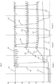
- Fig. 2 shows a representation of pressure curves.
- the reference symbol P2 denotes the pressure P2 or its time course in the individual phases 1, 2, 3. It can be seen that the P2 pressure reservoir is already filled with the pressure P2 at the start of work. During production, this pressure P2 fluctuates during the finished blowing phase because the plastic preforms are pressurized in the individual forming stations but compressed air continues to be supplied from outside.
- the reference symbol P1 indicates the pre-blow pressure, which is already applied to the corresponding pressure reservoir at the beginning of production.
- phase 2 the intermediate blowing pressures continue to build up and are then essentially constant in phase 3.
- the containers are only subjected to the first pressure P1 and the third pressure P2, so there is no intermediate blowing.
- the pressure reservoirs for the intermediate blowing pressures are also filled and so pressure slowly builds up in these pressure reservoirs.
- phase 2 the two intermediate pressure levels are also used in the blowing phase. Recycling takes place here into the intermediate blowing pressure levels Pi1 and Pi2.
- phase 3 is triggered.
- phase 3 which preferably represents the above-mentioned first operating mode or normal working operation, compressed air is now also returned to the P1 compressed air reservoir.
- reactions are preferably carried out in different ways.
- control device in particular a dome pressure regulator.
- a change between the individual phases 1 - 3 is preferably carried out depending on the presence or absence of the starting conditions.
- this reservoir can be fed via recycled air or fresh air, in particular depending on the state of the pressure levels Pi1 and Pi2.
- the valve switching can also be offset and/or switched to synchronous supply or pressure extraction.
Landscapes
- Engineering & Computer Science (AREA)
- Manufacturing & Machinery (AREA)
- Mechanical Engineering (AREA)
- Life Sciences & Earth Sciences (AREA)
- Sustainable Development (AREA)
- Blow-Moulding Or Thermoforming Of Plastics Or The Like (AREA)
Abstract
Verfahren zum Umformen von Kunststoffvorformlingen (10) zu Kunststoffbehältnissen (15) wobei eine Transporteinrichtung (2) die Kunststoffvorformlinge (10) entlang eines vorgegebenen Transportpfads (P) transportiert, wobei die Transporteinrichtung einen drehbaren Transportträger (22) aufweist, an dem eine Vielzahl von Umformungsstationen zum Umformen der Kunststoffvorformlinge (10) zu den Kunststoffbehältnissen (15) angeordnet ist, wobei die Umformungsstationen jeweils Beaufschlagungseinrichtungen (84) aufweisen, welche die Kunststoffvorformlinge mit dem fließfähigen Medium beaufschlagen und wobei die Vorrichtung (1) wenigstens drei Druckreservoirs aufweist, welche das fließfähige und insbesondere gasförmige Medium speichern und die Kunststoffvorformlinge in einem ersten Betriebsmodus zur ihrer Expansion mit einem ersten in dem ersten Druckreservoir (2a) gespeicherten Druckniveau (P1), wenigstens einem zweiten in dem zweiten Druckreservoir gespeicherten Druckniveau (Pi1) und einem dritten in dem dritten Druckreservoir gespeicherten Druckniveau (P2) beaufschlagt werden, wobei das zweite Druckniveau (Pi1) höher ist als das erste Druckniveau (P1) und das dritte Druckniveau (P2) höher ist als das zweite Druckniveau (Pi1) dadurch gekennzeichnet, dass die Vorrichtung (1) zeitweise in einem zweiten Betriebsmodus betrieben wird, wobei sich dieser zweite Betriebsmodus durch ein in dem zweiten Druckreservoir herrschendes Druckniveau von dem ersten Betriebsmodus unterscheidet.Method for forming plastic preforms (10) into plastic containers (15), wherein a transport device (2) transports the plastic preforms (10) along a predetermined transport path (P), the transport device having a rotatable transport carrier (22) on which a plurality of forming stations for forming the plastic preforms (10) into the plastic containers (15), the forming stations each having loading devices (84) which apply the flowable medium to the plastic preforms and the device (1) having at least three pressure reservoirs which supply the flowable and in particular store gaseous medium and the plastic preforms in a first operating mode for their expansion with a first pressure level (P1) stored in the first pressure reservoir (2a), at least a second pressure level (Pi1) stored in the second pressure reservoir and a third pressure level stored in the third pressure reservoir Pressure level (P2) are applied, the second pressure level (Pi1) being higher than the first pressure level (P1) and the third pressure level (P2) being higher than the second pressure level (Pi1), characterized in that the device (1) is temporarily in is operated in a second operating mode, this second operating mode differing from the first operating mode by a pressure level prevailing in the second pressure reservoir.
Description
Die vorliegende Erfindung betrifft ein Verfahren und eine Vorrichtung zum Umformen von Kunststoffvorformlingen zu Kunststoffbehältnissen. Derartige Verfahren und Vorrichtungen sind aus dem Stand der Technik seit langem bekannt. Dabei werden erwärmte Kunststoffvorformlinge durch Beaufschlagung mit einem fließfähigen Medium, insbesondere mit Druckluft zu Kunststoffbehältnissen und insbesondere Kunststoffflaschen umgeformt.The present invention relates to a method and a device for forming plastic preforms into plastic containers. Such methods and devices have long been known from the prior art. In this case, heated plastic preforms are formed into plastic containers and in particular plastic bottles by exposure to a flowable medium, in particular compressed air.
Diese Umformungsprozesse sind im Laufe der Zeit stets aufwendiger geworden, da nicht nur zufriedenstellende Behältnisse erzeugt werden sollen, sondern dabei möglichst auch Druckluft und damit Energie eingespart werden soll.These forming processes have become more and more complex over time, as not only should satisfactory containers be produced, but compressed air and thus energy should also be saved if possible.
Im Stand der Technik ist es bekannt, dass die Kunststoffvorformlinge mit mehreren Druckstufen bzw. Druckniveaus beaufschlagt werden, um sie zu expandieren. So ist bekannt, dass zunächst ein Vorblasdruck verwendet wird, anschließend eine Zwischenblasdruckstufe und schließlich ein Fertigblasdruck, um das Behältnis vollständig auszuformen und zu stabilisieren.It is known in the prior art that the plastic preforms are subjected to several pressure stages or pressure levels in order to expand them. It is known that first a pre-blowing pressure is used, then an intermediate blowing pressure stage and finally a finished blowing pressure in order to completely shape and stabilize the container.
Im Stand der Technik ist dabei eine Zwischenblasstufe vorgesehen und der Bediener gibt einen Solldruck vor, der für diese Blasstufe verwendet werden soll. Ein entsprechendes Druckreservoir wie beispielsweise ein Ringkanal hängt dabei stets in einer übergeordneten Versorgungsbaugruppe, welche über einen Domdruckminderer und ein Proportionalventil Frischluft nachfördern kann und welche weiterhin über eine Entlastungeinheit verfügen kann, welche Luft aus dem Druckreservoir gegen Atmosphäre entlasten kann.In the prior art, an intermediate blowing stage is provided and the operator specifies a target pressure that should be used for this blowing stage. A corresponding pressure reservoir, such as an annular channel, always hangs in a higher-level supply assembly, which has a dome pressure reducer and a proportional valve Fresh air can be supplied and which can also have a relief unit which can relieve air from the pressure reservoir against the atmosphere.
Ein Problem besteht hierbei darin, dass der energetisch perfekte Sollwert dem Maschinenbediener nicht bekannt ist. Der ideale Druck wird in der Praxis meist anhand einer Faustformel nur annäherungsweise ermittelt. Daneben ist es im Stand der Technik nötig, sämtliche Druckreservoirs und auch diejenigen für die Zwischendruckstufe vorzubefüllen. Es hat sich auch gezeigt, dass die Luftrückgewinnungsregelung für zusätzliche Zwischenblasstufen nicht mehr praktikabel ist. Ideale Drücke für den Zwischendruck sind nur über umfangreiche Berechnungen zu ermitteln.One problem here is that the energetically perfect setpoint is not known to the machine operator. In practice, the ideal pressure is usually only approximately determined using a rule of thumb. In addition, in the prior art it is necessary to prefill all pressure reservoirs and also those for the intermediate pressure stage. It has also been shown that air recovery control for additional intermediate blowing stages is no longer practical. Ideal pressures for the intermediate pressure can only be determined through extensive calculations.
Der vorliegenden Erfindung liegt daher die Aufgabe zugrunde, derartige Vorrichtungen und Verfahren einerseits effizienter zu gestalten und andererseits kostengünstiger auszugestalten. Dies wird erfindungsgemäß durch die Gegenstände der unabhängigen Patentansprüche erreicht. Vorteilhafte Ausführungsformen und Weiterbildungen sind Gegenstand der Unteransprüche.The present invention is therefore based on the object of making such devices and methods more efficient on the one hand and, on the other hand, making them more cost-effective. This is achieved according to the invention by the subject matter of the independent patent claims. Advantageous embodiments and further developments are the subject of the subclaims.
Bei einem erfindungsgemäßen Verfahren zum Umformen von Kunststoffvorformlingen zu Kunststoffbehältnissen transportiert eine Transporteinrichtung die Kunststoffvorformlinge entlang eines vorgegebenen Transportpfads, wobei die Transporteinrichtung einen drehbaren Transportträger aufweist, an dem eine Vielzahl von Umformungsstationen zum Umformen der Kunststoffvorformlinge zu den Kunststoffbehältnissen angeordnet ist und wobei die Umformungsstationen jeweils Beaufschlagungseinrichtungen aufweisen, welche die Kunststoffvorformlinge mit dem fließfähigen Medium beaufschlagen und wobei die Vorrichtung wenigstens drei Druckreservoirs und insbesondere Druckluftreservoirs aufweist, welche das fließfähige und insbesondere gasförmige Medien speichern und die Kunststoffvorformlinge in einem ersten Betriebsmodus zu ihrer Expansion mit einem ersten in dem ersten Druckreservoir gespeicherten Druckniveau, wenigstens einem zweiten in dem zweiten Druckreservoir gespeicherten Druckniveau und einem dritten in den dritten Druckreservoir gespeicherten Druckniveau beaufschlagt werden, wobei das zweite Druckniveau höher ist als das erste Druckniveau und das dritte Druckniveau höher ist als das zweite Druckniveau.In a method according to the invention for forming plastic preforms into plastic containers, a transport device transports the plastic preforms along a predetermined transport path, the transport device having a rotatable transport carrier on which a plurality of forming stations for forming the plastic preforms into the plastic containers is arranged and the forming stations each having loading devices , which apply the flowable medium to the plastic preforms and wherein the device has at least three pressure reservoirs and in particular compressed air reservoirs which store the flowable and in particular gaseous media and the plastic preforms in a first operating mode for their expansion with a first pressure level stored in the first pressure reservoir, at least a second pressure level stored in the second pressure reservoir and a third pressure level stored in the third pressure reservoir, the second pressure level being higher than the first pressure level and the third pressure level being higher than the second pressure level.
Besonders bevorzugt wird die Vorrichtung wenigstens zeitweise in einem zweiten Betriebsmodus betrieben, wobei sich dieser zweite Betriebsmodus durch ein in dem zweiten Druckreservoir herrschendes Druckniveau von dem ersten Betriebsmodus unterscheidet.
Es wird daher vorgeschlagen, dass zwei verschiedene Betriebsmodi zur Verfügung stehen, bzw. wenigstens zwei Betriebsmodi, welche sich insbesondere durch die Ausgestaltung des zweiten Druckniveaus, bei dem es sich bevorzugt um einen Zwischenblasdruck handelt, unterscheiden.Particularly preferably, the device is operated at least temporarily in a second operating mode, this second operating mode being characterized by a pressure reservoir in the second prevailing pressure level differs from the first operating mode.
It is therefore proposed that two different operating modes are available, or at least two operating modes, which differ in particular in the design of the second pressure level, which is preferably an intermediate blowing pressure.
Besonders bevorzugt, handelt es sich bei dem ersten Druckniveau um einen Vorblasdruck, im Folgenden auch mit P1 bezeichnet, mit welchem die Behältnisse zu Beginn der Expansion vorgeblasen werden. Bei dem zweiten Druckniveau handelt es sich besonders bevorzugt um einen (ersten) Zwischenblasdruck, im Folgenden auch mit Pi1 bezeichnet und bei dem dritten Druckniveau handelt es sich besonders bevorzugt um einen Fertigblasdruck (im Folgenden auch mit P2 bezeichnet), mit welchem das Behältnis vollständig ausgeformt und bevorzugt auch in einer ausgeformten Stellung eine Zeit lang gehalten wird. Bevorzugt werden die Behältnisse demnach mit einem ersten Druck (Vorblasdruck), einen dritten Druck (Fertigblasdruck) und mindestens einen zweiten Druck (Zwischenblasdruck) beaufschlagt bzw. sind ein erster Druck (Vorblasdruck), ein dritter Druck (Fertigblasdruck) und mindestens ein zweiter Druck (Zwischenblasdruck) vorhanden. Denkbar wären also n-Zwischenblasdrücke (Pi1, Pi2, PiN), so dass das Behältnis bevorzugt mit mehreren Zwischenblasdrücken beaufschlagt wird bzw. das Zwischenblasen auf mehreren Stufen erfolgt.Particularly preferably, the first pressure level is a pre-blow pressure, hereinafter also referred to as P1, with which the containers are pre-blasted at the beginning of the expansion. The second pressure level is particularly preferably a (first) intermediate blowing pressure, hereinafter also referred to as Pi1, and the third pressure level is particularly preferably a finished blowing pressure (hereinafter also referred to as P2), with which the container is completely formed and is preferably held in a shaped position for a while. The containers are therefore preferably subjected to a first pressure (pre-blow pressure), a third pressure (finished blowing pressure) and at least a second pressure (intermediate blowing pressure) or are a first pressure (pre-blow pressure), a third pressure (finished blowing pressure) and at least a second pressure ( Intermediate blowing pressure) available. It would therefore be conceivable to have n intermediate blowing pressures (Pi1, Pi2, PiN), so that the container is preferably subjected to several intermediate blowing pressures or the intermediate blowing takes place at several stages.
Bei einem weiteren bevorzugten Verfahren werden die Kunststoffvorformlinge auch mittels einer Reckeinheit gereckt. Zu diesem Zweck wird bevorzugt eine Reckstange in die Kunststoffvorformlinge eingeführt, um diese in deren Längsrichtung zu dehnen.In a further preferred method, the plastic preforms are also stretched using a stretching unit. For this purpose, a stretching rod is preferably inserted into the plastic preforms in order to stretch them in their longitudinal direction.
Bei einem weiteren bevorzugten Verfahren ist der zweite Betriebsmodus ein Startbetrieb der Vorrichtung bzw. ein Anfahrbetrieb, in dem diese in Betrieb genommen wird. Bevorzugt ist zumindest zu dem Beginn dieses zweiten Betriebsmodus, d. h. des Startbetriebs nur das erste Druckreservoir und das dritte Druckreservoir mit Druckluft gefüllt und/oder es sind nur das erste und das dritte Druckreservoir mit der Frischluft befüllt. Unter Frischluft wird dabei von außen kommende Luft verstanden, die beispielsweise durch einen Kompressor oder durch einen Drehverteiler zugeführt wird. Das zweite Druckreservoir ist bevorzugt am Anfang drucklos bzw. weist im Wesentlichen den Außendruck auf.In a further preferred method, the second operating mode is a starting operation of the device or a starting operation in which it is put into operation. It is preferred at least at the beginning of this second operating mode, i.e. H. During start-up operation, only the first pressure reservoir and the third pressure reservoir are filled with compressed air and/or only the first and the third pressure reservoir are filled with fresh air. Fresh air is understood to mean air coming from outside, which is supplied, for example, by a compressor or a rotary distributor. The second pressure reservoir is preferably initially unpressurized or essentially has the external pressure.
Besonders bevorzugt wird in keinem der beiden Betriebsmodi und insgesamt nicht an das zweite Druckreservoir Frischluft bzw. Luft von außen zugeführt.Particular preference is given to neither of the two operating modes and not to that overall second pressure reservoir fresh air or air supplied from outside.
Besonders bevorzugt werden in dem zweiten Betriebsmodus wenigstens zeitweise die Kunststoffvorformlinge nur mit dem ersten Druckniveau und dem zweiten Druckniveau beaufschlagt. Dies bedeutet, dass zu Beginn eines Prozesses lediglich das erste Druckniveau, d. h. der Vorblasdruck und das dritte Druckniveau, d. h. der Fertigblasdruck P2 auf das Behältnis gegeben werden bzw. der Kunststoffvorformling mit diesen Druckniveaus beaufschlagt wird.Particularly preferably, in the second operating mode, the plastic preforms are only subjected to the first pressure level and the second pressure level at least temporarily. This means that at the beginning of a process only the first pressure level, i.e. H. the pre-blow pressure and the third pressure level, i.e. H. the finished blowing pressure P2 is applied to the container or the plastic preform is subjected to these pressure levels.
Während dieser Anfangszeit steht in dem Zwischenblasdruckreservoir noch keine Druckluft zur Verfügung, sodass insoweit auch kein Zwischenblasen erfolgen kann.During this initial period, there is no compressed air available in the intermediate blowing pressure reservoir, so that no intermediate blowing can take place.
Besonders bevorzugt wird in wenigstens einem Betriebsmodus und bevorzugt den beiden Betriebsmodi wenigstens zeitweise Druckluft von den Umformungsstationen und/oder den Kunststoffbehältnissen zurück in das zweite Druckreservoir geleitet. Sind zwei oder mehr Zwischenblasstufen vorhanden, so wird bevorzugt in jedes Druckreservoir für den Zwischenblasdruck Druckluft recycelt bzw. jede Zwischenblasstufe wird mit recycelter Druckluft versorgt..Particularly preferably, in at least one operating mode and preferably the two operating modes, compressed air is fed back into the second pressure reservoir at least temporarily from the forming stations and/or the plastic containers. If there are two or more intermediate blowing stages, compressed air is preferably recycled into each pressure reservoir for the intermediate blowing pressure or each intermediate blowing stage is supplied with recycled compressed air.
Bei diesem bevorzugten Verfahren wird damit ein Recyclingprozess beschrieben, bei dem Blasluft wieder von den Behältnissen in einzelne Druckreservoirs, hier in das zweite Druckreservoir, geleitet wird. Auf diese Weise kann während der Anfahrtphase das zweite Druckreservoir mit Druckluft gefüllt werden, welche jedoch (insbesondere ausschließlich) von den zu behandelnden bzw. zu expandierenden Behältnissen stammt.In this preferred method, a recycling process is described in which blown air is directed again from the containers into individual pressure reservoirs, here into the second pressure reservoir. In this way, during the start-up phase, the second pressure reservoir can be filled with compressed air, which, however, comes (in particular exclusively) from the containers to be treated or expanded.
Ein derartiges Recycling von Blasluft bei der Expansion bzw. bei der Rückführung von Blasluft aus den Behältnissen ist an sich aus dem Stand der Technik bekannt. Die Erfindung schlägt hierzu vor, dieses Recycling auch gewissermaßen zum Erstbefüllen des zweiten Druckreservoirs zu verwenden.Such recycling of blown air during expansion or when returning blown air from the containers is known from the prior art. The invention proposes to use this recycling, so to speak, for the initial filling of the second pressure reservoir.
Damit wird faktisch vorgeschlagen, dass das zweite Druckreservoir über das Recycling bzw. mithilfe des Druckluftrecyclings befüllt wird.This effectively suggests that the second pressure reservoir is filled via recycling or with the help of compressed air recycling.
Bei einem weiteren bevorzugten Verfahren wird ein Druckniveau in dem zweiten Druckreservoir bestimmt und in Abhängigkeit von diesem Druckniveau in einem Betrieb von einem Betriebsmodus in einen anderen Betriebsmodus übergegangen. So kann beispielsweise festgestellt werden, dass das Druckverhalten im zweiten Druckreservoir einerseits ein bestimmtes soll Niveau erreicht hat und andererseits auch stabil ist. In diesem Fall kann dazu übergegangen werden, die Behältnisse nicht mehr nur vor-, sondern auch zwischenzublasen bzw. das zweite Druckreservoir auch aktiv in die Expansion der Behältnisse einzubinden.In a further preferred method, a pressure level in the second pressure reservoir determined and, depending on this pressure level, changed from one operating mode to another operating mode in one operation. For example, it can be determined that the pressure behavior in the second pressure reservoir has, on the one hand, reached a certain desired level and, on the other hand, is also stable. In this case, you can no longer just blow the containers forward, but also blow them in between, or actively integrate the second pressure reservoir into the expansion of the containers.
Es wird damit eine (zeitlich) erste Phase vorgeschlagen (die jedoch dem oben genannten zweiten Betriebsmodus entspricht), in welcher die ersten Behältnisse ohne den Zwischenblasdruck geblasen werden. In dieser Phase schließt sich daher an den Vorblasdruck P1 direkt die Beaufschlagung mit dem Fertigblasdruck P2 an. Andererseits wird jedoch in dieser Phase bereits in das wenigstens eine Zwischenblasdruckniveau (Pi1) recycelt. Da in dieser Phase nur rückgespeist, nicht aber abgenommen wird, steigt der Druck in dem betreffenden Druckreservoir bzw. Ringkanal von Behältnis zu Behältnis an. Wird ein bestimmtes Niveau in den Druckniveaus überschritten wechselt die Maschine in "Phase 2"A first (in terms of time) phase is therefore proposed (which, however, corresponds to the above-mentioned second operating mode), in which the first containers are blown without the intermediate blowing pressure. In this phase, the pre-blow pressure P1 is directly followed by the application of the finished blow pressure P2. On the other hand, in this phase, recycling is already taking place in the at least one intermediate blowing pressure level (Pi1). Since in this phase there is only feedback but not consumption, the pressure in the relevant pressure reservoir or ring channel increases from container to container. If a certain pressure level is exceeded, the machine switches to "
In Phase erfolgt ein Druckaufbau mit inzwischen dem wenigstens einen Zwischenblasdruckniveau und bevorzugt mit zwei Zwischenblasdruckniveaus.In phase, pressure builds up with at least one intermediate blowing pressure level and preferably with two intermediate blowing pressure levels.
Sobald das Druckniveau in dem einen Druckreservoir und bevorzugt in zwei Zwischendruckreservoirs stabil ist, kann die Vorrichtung in den zweiten Betriebsmodus (den normalen Arbeitsbetrieb) übergehen.As soon as the pressure level in one pressure reservoir and preferably in two intermediate pressure reservoirs is stable, the device can switch to the second operating mode (normal operating mode).
Bei einem weiteren bevorzugten Verfahren werden die Kunststoffvorformlinge mit einem weiteren Druckniveau beaufschlagt, wobei dieses weitere Druckniveau höher ist als das zweite Druckniveau jedoch geringer als das dritte Druckniveau. Bei diesem Verfahren wird vorgeschlagen, dass die Kunststoffvorformlinge mit zwei Zwischenblasdruckniveaus beaufschlagt werden. Bevorzugt wird auch in das Druckreservoirs des weiteren Druckniveaus recycelte Druckluft geleitet.In a further preferred method, the plastic preforms are subjected to a further pressure level, this further pressure level being higher than the second pressure level but lower than the third pressure level. In this process it is proposed that the plastic preforms are subjected to two intermediate blowing pressure levels. Recycled compressed air is preferably also fed into the pressure reservoir of the further pressure level.
Bevorzugt steht für dieses weitere Druckniveau ein weiteres Druckreservoir und insbesondere ein Ringkanal zur Verfügung. Bevorzugt wird auch dieses weitere Druckreservoir zu Beginn eines Umformungsvorgangs nicht befüllt und/oder dieses weitere Druckreservoir wird nicht mit Frischluft und/oder mit Luft von außen befüllt.A further pressure reservoir and in particular an annular channel are preferably available for this further pressure level. Preferably, this additional pressure reservoir is not filled at the beginning of a forming process and/or this additional pressure reservoir is not filled with fresh air and/or with air from outside.
Bei einem weiteren bevorzugten Verfahren werden Arbeitsparameter für die Beaufschlagung mit dem ersten und/oder dritten Druckniveau vorgegeben, insbesondere durch einen Benutzer vorgegeben. So kann beispielsweise durch einen Benutzer vorgegeben werden, welche Druckhöhe das erste und das dritte Druckniveau haben sollen, wann entsprechende Ventile öffnen und schließen sollen, um die Kunststoffvorformlinge zu beaufschlagen.In a further preferred method, working parameters for the application of the first and/or third pressure level are specified, in particular specified by a user. For example, a user can specify what pressure level the first and third pressure levels should have, and when corresponding valves should open and close in order to pressurize the plastic preforms.
Bei einem weiteren bevorzugten Verfahren werden Arbeitsparameter für die Beaufschlagung mit dem zweiten Druckniveau durch eine Steuerungseinrichtung ermittelt. Auf diese Weise ist es möglich, dass wiederum ein Druckbeginn oder ein Druckende oder eine Druckdauer vorgegeben werden. Besonders bevorzugt ermittelt daher die Steuerung beispielsweise ideale Druckhöhen und Druckzeiten für die Zwischenblasdruckstufen.In a further preferred method, working parameters for the application of the second pressure level are determined by a control device. In this way it is possible for a start or end of printing or a printing duration to be specified. The control therefore particularly preferably determines, for example, ideal pressure levels and printing times for the intermediate blowing pressure stages.
Besonders bevorzugt wird daher kein Solldruck mehr für die Zwischenblasdruckstufen PI1 und Pi2 vorgegeben. Stattdessen findet bevorzugt die Vorrichtung selbst ein Optimum für diese Drücke (und/oder Beaufschlagungszeiten).It is therefore particularly preferred that no target pressure is specified for the intermediate blowing pressure stages PI1 and Pi2. Instead, the device itself preferably finds an optimum for these pressures (and/or exposure times).
Bevorzugt sind Rahmenbedingung hierfür konstante Luftabnahme und Luftrückgewinnungszeiten. Im ersten Entwicklungsschritt können diese bevorzugt als fest angenommen werden. In weiteren Ausführungsformen wären auch geregelte Druckanstiegs- und Recyclingzeiten denkbar.The preferred framework conditions for this are constant air removal and air recovery times. In the first development step, these can preferably be assumed to be fixed. In further embodiments, regulated pressure rise and recycling times would also be conceivable.
Ein Vorteil dieser Ausführungsform besteht darin, dass Druckminderer und Prop-Ventile für die jeweiligen Druckreservoirs Pi1 und Pi2 entfallen.An advantage of this embodiment is that there is no need for pressure reducers and prop valves for the respective pressure reservoirs Pi1 and Pi2.
Bei einer bevorzugten Ausführungsform kann jedoch ein einzelnes Ventil zu Service- oder Diagnosezwecken zur Verfügung stehen oder zum Vorbefüllen des Kanals.However, in a preferred embodiment, a single valve may be available for service or diagnostic purposes or for pre-filling the channel.
Im Folgenden wird ein in mehrere Phasen unterteilter Startbetrieb für eine derartige Vorrichtung beschrieben:
In einer ersten Phase (Phase 1) werden die ersten Flaschen werden ohne Pi d.h. ohne die Zwischenblasdrücke geblasen. Es schließt sich nach P1 also unmittelbar P2 an. Auf der Rückgewinnungsseite wird jedoch Pi2 und Pi1 recycelt. Da nur rückgespeist, nicht aber abgenommen wird, steigt der Druck im Ringkanal von Flasche zu Flasche an. Wird ein bestimmtes Niveau in den Ringkanälen überschritten wechselt die Maschine in die zweite Phase, d.h. in "Phase 2"A starting operation for such a device, divided into several phases, is described below:
In a first phase (phase 1) the first bottles are blown without Pi, ie without the intermediate blowing pressures. After P1 it immediately follows P2. However, on the recovery side, Pi2 and Pi1 are recycled. Since it is only fed back, not taken away the pressure in the annular channel increases from bottle to bottle. If a certain level in the ring channels is exceeded, the machine switches to the second phase, ie "
Die zweite Phase ("Phase 2") wird eingeleitet, wenn bestimmte Startbedingungen erfüllt werden, beispielsweise der Zwischenblasdruck Pi1 größer ist als 1/3 des Fertigblasdrucks P2 und der Zwischenblasdruck Pi2 größer ist als 2/3 des Fertigblasdrucks P2.The second phase ("
Sobald die Ringkanaldrücke die Startbedingung erreichen bzw. überschreiten wechselt die Steuerung in Phase 2. Hier wird nun erstmals neben P1 und P2 auch Pi1 und Pi2 beim Druckaufbau geschalten. Auf der Rückgewinnungsseite schalten nach wie vor Pi2 und Pi1. Durch die festen Druckaufbau- und Recyclingzeiten pendelt sich ein gewisser Pi1- und Pi2-Druck ein. Diese zweite Phase ist bevorzugt eine Übergangsphase zwischen dem oben beschriebenen zweiten Betriebsmodus und dem ersten Betriebsmodus.As soon as the ring channel pressures reach or exceed the starting condition, the control switches to
Bevorzugt wird daher die Vorrichtung in wenigstens drei unterschiedlichen Betriebsmodi betrieben, wobei der dritte Betriebsmodus bevorzugt ein Übergangsmodus zwischen dem zweiten Betriebsmodus und dem ersten Betriebsmodus ist und/oder der dritte Betriebsmodus zeitlich zwischen dem zweiten Betriebsmodus und dem ersten Betriebsmodus liegt.The device is therefore preferably operated in at least three different operating modes, wherein the third operating mode is preferably a transition mode between the second operating mode and the first operating mode and/or the third operating mode lies temporally between the second operating mode and the first operating mode.
An die zweite Phase schließt sich bevorzugt eine dritte Phase ("Phase 3") an.The second phase is preferably followed by a third phase (“
Auch für diese dritte Phase wird bevorzugt eine Startbedingung definiert, diese kann beispielsweise darin bestehen, dass die Zwischenblasdrücke Pi1 und Pi2 stabil sind und der Zwischenblasdruck Pi1 größer ist als der Vorblasdruck P1. Daneben können hier auch noch die obigen Bedingungen für den Start von Phase 2 gelten.A starting condition is also preferably defined for this third phase; this can, for example, consist of the intermediate blowing pressures Pi1 and Pi2 being stable and the intermediate blowing pressure Pi1 being greater than the pre-blowing pressure P1. In addition, the above conditions for the start of
Die Maschine geht in Phase 3 über, wenn sich die Ringkanaldrücke für Pi1 und Pi2 stabilisiert haben. Grundvoraussetzung ist jedoch, dass Pi1 noch über P1 liegt. Sind alle Bedingungen erfüllt kommt mit Phase 3 nun auch das P1 Recycling zum Zug. Die P1 Recycling Regelung agiert dabei wie an sich im Stand der Technik bekannt. Mit Phase 3 befindet sich die Maschine im Vollbetrieb und/oder dem oben genannten ersten Betriebsmodus.The machine moves to
Bevorzugt vollzieht sich der gesamte Ablauf von Phase 1-3 im Allgemeinen in nur wenigen Sekunden. Der stabile eingeschwungene Zustand wird somit relativ schnell erreicht.Preferably, the entire process of phases 1-3 generally takes place in just a few seconds. The stable steady state is therefore achieved relatively quickly.
Wird eine Startbedingung nicht mehr erfüllt wechselt das System bevorzugt automatisch zurück in die vorherige Phase. Dieses Umschalten kann jederzeit in Echtzeit erfolgen und stellt bevorzugt eine Antwortreaktion auf eine bestimmte Maschinensituation dar. Mit dieser Methode gelingt es Störeinflüsse, wie z.B. Leckagen, Flaschenplatzer, Ausleitung von Vorblasflaschen, oder abgeschaltene Stationen, abzufangen.If a starting condition is no longer met, the system preferably automatically switches back to the previous phase. This switching can take place at any time in real time and preferably represents a response to a specific machine situation. This method makes it possible to absorb disruptive influences such as leaks, bottle bursts, rejection of pre-blow bottles, or switched off stations.
Durch die Erfindung ist es nun auch möglich Pi Drücke d.h. Zwischenblasdrücke anzuwenden, die niedriger sind als P1. Der Entlastungsdruck ist damit losgelöst vom P1 Druck, wenngleich es natürlich für den Luftverbrauch immer noch vorteilhaft ist P1 vollständig über Recycling zu speisen.The invention now also makes it possible to use Pi pressures, i.e. intermediate blowing pressures, that are lower than P1. The relief pressure is therefore independent of the P1 pressure, although it is of course still advantageous for air consumption to feed P1 entirely via recycling.
Daneben bietet das erfindungsgemäße Verfahren eine wirksame Methode, um Störeinflüsse zu bewältigen.In addition, the method according to the invention offers an effective method for dealing with disruptive influences.
Weiterhin können perfekte Ringkanaldrücke (insbesondere für das Zwischenblasen) für jeden Blasprozess, insbesondere für Blasprozesse mit zwei oder mehr Zwischenblasstufen zur Verfügung gestellt werden.Furthermore, perfect ring channel pressures (especially for intermediate blowing) can be provided for every blowing process, in particular for blowing processes with two or more intermediate blowing stages.
Die vorliegende Erfindung ist weiterhin auf eine Vorrichtung zum Umformen von Kunststoffvorformlingen zur Kunststoffbehältnissen gerichtet mit einer Transporteinrichtung, welche die Kunststoffvorformlinge entlang eines vorgegebenen Transportpfads P transportiert, wobei die Transporteinrichtung einen drehbaren Transportträger aufweist, an dem eine Vielzahl von Umformungsstationen zum Umformen der Kunststoffvorformlinge zu den Kunststoffbehältnissen angeordnet ist. Dabei weisen die Umformungsstationen jeweils Beaufschlagungseinrichtungen (insbesondere Blasdüsen) auf, welche die Kunststoffvorformlinge mit dem fließfähigen Medium beaufschlagen und die Vorrichtung weist wenigstens drei Reservoirs bzw. Druckreservoirs auf, welche das fließfähige und insbesondere gasförmige Medium speichern.The present invention is further directed to a device for forming plastic preforms into plastic containers with a transport device which transports the plastic preforms along a predetermined transport path P, the transport device having a rotatable transport carrier on which a plurality of forming stations for forming the plastic preforms into plastic containers is arranged. The forming stations each have loading devices (in particular blowing nozzles) which apply the flowable medium to the plastic preforms and the device has at least three reservoirs or pressure reservoirs which store the flowable and in particular gaseous medium.
Weiterhin sind die Kunststoffvorformlinge in einem ersten Betriebsmodus zu ihrer Expansion mit einem ersten in dem ersten Druckreservoir gespeicherten Druckniveau, wenigstens einem zweiten in dem zweiten Druckreservoir gespeicherten Druckniveau und einem Dritten in dem dritten Druckreservoir gespeicherten Druckniveau beaufschlagbar, wobei das zweite Druckniveau höher ist als das erste Druckniveau und das dritte Druckniveau höher ist als das zweite Druckniveau.Furthermore, the plastic preforms are in a first operating mode for their expansion with a first pressure level stored in the first pressure reservoir, at least a second pressure level stored in the second pressure reservoir and a third in The pressure level stored in the third pressure reservoir can be acted upon, the second pressure level being higher than the first pressure level and the third pressure level being higher than the second pressure level.
Erfindungsgemäß ist die Vorrichtung zeitweise in einem zweiten Betriebsmodus betreibbar, wobei sich dieser zweite Betriebsmodus durch einen im zweiten Druckreservoir herrschendes Druckniveau von dem ersten Betriebsmodus unterscheidet. Bei einer weiteren erfindungsgemäßen Ausgestaltung weist die Vorrichtung eine Frischluftversorgungseinrichtung auf, welche derart ausgebildet ist, dass sie das erste und dritte Druckreservoir, nicht jedoch das zweite Druckreservoir mit Frischluft beaufschlagt.According to the invention, the device can be operated temporarily in a second operating mode, this second operating mode differing from the first operating mode by a pressure level prevailing in the second pressure reservoir. In a further embodiment according to the invention, the device has a fresh air supply device, which is designed such that it supplies fresh air to the first and third pressure reservoir, but not to the second pressure reservoir.
Besonders bevorzugt weist die Frischluftversorgungseinrichtung einen Kompressor oder einen Druckanschluss auf. Weiterhin weist die Vorrichtung bevorzugt eine Verteilereinrichtung auf, welche die Druckluft ausgehend von der Frischluftversorgungseinrichtung auf den drehbaren Träger und insbesondere zu den Druckreservoirs leitet. Bevorzugt ist die Verteileinrichtung als Drehverteiler ausgebildet.The fresh air supply device particularly preferably has a compressor or a pressure connection. Furthermore, the device preferably has a distribution device which directs the compressed air from the fresh air supply device to the rotatable carrier and in particular to the pressure reservoirs. The distribution device is preferably designed as a rotary distributor.
Bei einer weiteren bevorzugten Ausführungsform sind die Druckreservoirs Ringkanäle. Besonders bevorzugt sind diese Druckreservoirs an dem drehbaren Träger angeordnet.In a further preferred embodiment, the pressure reservoirs are ring channels. These pressure reservoirs are particularly preferably arranged on the rotatable carrier.
Bei einer weiteren vorteilhaften Ausführungsform weist die Vorrichtung eine Vielzahl von Sensor- und/oder Messeinrichtungen auf, um Betriebsparameter zu bestimmen. Besonders bevorzugt ist jedem Druckreservoir wenigstens eine Druckmesseinrichtung zugeordnet. Besonders bevorzugt sind auch eine oder mehrere Durchflussmesseinrichtungen vorgesehen, welche eine Durchflussmenge von Luft bestimmen, die von einem Druckreservoir zu den jeweiligen Umformungsstationen gelangt.In a further advantageous embodiment, the device has a large number of sensor and/or measuring devices in order to determine operating parameters. Particularly preferably, at least one pressure measuring device is assigned to each pressure reservoir. Particularly preferably, one or more flow measuring devices are also provided, which determine a flow rate of air that reaches the respective forming stations from a pressure reservoir.
Bei einer weiteren vorteilhaften Ausführungsform weist die Vorrichtung eine Regeleinrichtung auf, um einen Druck in den Druckreservoirs festzulegen. Dies ist insbesondere für das erste und dritte Druckreservoir gegeben. Besonders bevorzugt handelt es sich bei der Regeleinrichtung um einen Domdruckregler.In a further advantageous embodiment, the device has a control device in order to set a pressure in the pressure reservoirs. This is particularly the case for the first and third pressure reservoirs. The control device is particularly preferably a dome pressure regulator.
Bei einer weiteren vorteilhaften Ausführungsform weist die Vorrichtung ein weiteres Druckreservoir auf, welches dazu geeignet und bestimmt ist, die Kunststoffvorformlinge mit einem weiteren Druckniveau zu beaufschlagen. Insbesondere handelt es sich hierbei um ein weiteres Zwischenblasdruckniveau. Besonders bevorzugt wird auch dieses weitere Druckreservoir nicht mit Frischluft versorgt.In a further advantageous embodiment, the device has a further pressure reservoir, which is suitable and intended for the plastic preforms with a to apply further pressure levels. In particular, this is a further intermediate blowing pressure level. It is particularly preferred that this additional pressure reservoir is not supplied with fresh air.
Besonders bevorzugt ist Druckluft von den Kunststoffbehältnissen in wenigstens ein Druckreservoir führbar bzw. rückführbar. Besonders bevorzugt handelt es sich dabei wenigstens um das zweite Druckreservoir für einen Zwischenblasdruck und/oder das weitere Druckreservoir für den weiteren Zwischenblasdruck und/oder das Druckreservoir für den oben genannten ersten Druck.Particularly preferably, compressed air can be guided or returned from the plastic containers into at least one pressure reservoir. Particularly preferably, this is at least the second pressure reservoir for an intermediate blowing pressure and/or the further pressure reservoir for the further intermediate blowing pressure and/or the pressure reservoir for the above-mentioned first pressure.
Weitere Vorteile ergeben sich aus den beigefügten Zeichnungen. Darin zeigen:
- Fig. 1
- eine schematische Darstellung einer erfindungsgemäßen Vorrichtung;
- Fig. 2
- eine Darstellung von Druckverläufen in den unterschiedlichen Phasen; und
- Fig. 3
- eine Darstellung zur Veranschaulichung des Übergangs zwischen den Phasen.
- Fig. 1
- a schematic representation of a device according to the invention;
- Fig. 2
- a representation of pressure curves in the different phases; and
- Fig. 3
- a representation to illustrate the transition between phases.
Das Bezugszeichen 84 kennzeichnet eine Beaufschlagungseinrichtung, welche zum Expandieren der Kunststoffvorformlinge 10 dient. Hierbei kann es sich beispielsweise um eine Blasdüse handeln, welche an eine Mündung der Kunststoffvorformlinge anlegbar ist, um diese so zu expandieren. Daneben wäre es auch denkbar, dass die Blasdüse an der Blasformeinrichtung abdichtet. Bevorzugt ist diese Beaufschlagungseinrichtung in einer Längsrichtung und bevorzugt ausschließlich in einer Längsrichtung der Kunststoffvorformlinge bewegbar.The
Das Bezugszeichen 90 kennzeichnet eine Ventilanordnung wie einen Ventilblock, der bevorzugt eine Vielzahl von Ventilen aufweist, welche die Beaufschlagung der Kunststoffvorformlinge mit unterschiedlichen Druckniveaus steuern. Bevorzugt weist jede Umformungsstation einen derartigen Ventilblock auf.The
Bei einem bevorzugten Verfahren werden die Kunststoffvorformlinge zunächst mit einem Vorblasdruck P1 beaufschlagt, anschließend mit mindestens einem Zwischenblasdruck Pi, der höher ist als der Vorblasdruck und schließlich mit einem Fertigblasdruck P2, der höher ist als der Zwischenblasdruck Pi1. Besonders bevorzugt werden die Kunststoffvorformlinge mit einem weiteren Zwischenblasdruck Pi2 beaufschlagt, der größer ist als der Druck Pi1 jedoch kleiner als der Druck P2.In a preferred method, the plastic preforms are first subjected to a pre-blowing pressure P1, then to at least one intermediate blowing pressure Pi, which is higher than the pre-blowing pressure, and finally to a finished blowing pressure P2, which is higher than the intermediate blowing pressure Pi1. Particularly preferably, the plastic preforms are subjected to a further intermediate blowing pressure Pi2, which is greater than the pressure Pi1 but smaller than the pressure P2.
Nach der Expansion der Kunststoffbehältnisse werden bevorzugt die Drücke bzw. die Druckluft wieder von dem Behältnis in die einzelnen Druckreservoirs zurückgeführt.After the plastic containers have expanded, the pressures or compressed air are preferably returned from the container to the individual pressure reservoirs.
Das Bezugszeichen 88 kennzeichnet eine Reckstange, die dazu dient, die Kunststoffvorformlinge in ihrer Längsrichtung zu dehnen. Bevorzugt weisen sämtliche Umformungsstationen derartige Blasformen 82 sowie Reckstangen 88 auf. Diese Reckstange ist bevorzugt Bestandteil einer mit 30 bezeichneten Reckeinrichtung. Die Reckstange ist (bevorzugt ebenfalls ausschließlich) in der Längsrichtung der Kunststoffvorformlinge 10 beweglich.Reference numeral 88 denotes a stretching rod which serves to stretch the plastic preforms in their longitudinal direction. All forming stations preferably have
Bevorzugt liegt die Anzahl dieser Umformungsstationen 4 zwischen 2 und 100, bevorzugt zwischen 4 und 60, bevorzugt zwischen 6 und 40.The number of these forming
Die Kunststoffvorformlinge 10 werden über eine erste Transporteinrichtung 62 wie insbesondere aber nicht ausschließlich einen Transportstern der Vorrichtung zugeführt. Über eine zweite Transporteinrichtung 64 werden die Kunststoffbehältnisse 15 abtransportiert.The plastic preforms 10 are fed to the device via a
Das Bezugszeichen 7 kennzeichnet eine Druckbereitstellungseinrichtung wie etwa einen Kompressor oder auch einen Druckluftanschluss. Die Druckluft wird über eine Verbindungsleitung 72 zu einem Drehverteiler 74 gefördert und von diesem über eine weitere Leitung 76 an das Druckluftreservoir 2a angegeben, bei dem es sich hier um einen Ringkanal handelt. Damit dient bevorzugt dieser Drehverteiler zu dem Zweck, Luft von einem stationären Teil der Vorrichtung in einen sich drehenden Teil der Vorrichtung zu führen.The
Neben diesem dargestellten Ringkanal 2a sind bevorzugt noch weitere Ringkanäle vorgesehen, die in der in
Das Bezugszeichen 32 kennzeichnet eine Verbindungsleitung, welche die Druckluft an eine Umformungsstation 4 bzw. deren Ventilblock 90 abgibt. Bevorzugt ist jeder der Ringkanäle über entsprechende Verbindungsleitungen mit sämtlichen Umformungsstationen verbunden. Diese Verbindungsleitung ist bevorzugt in dem drehenden Teil der Vorrichtung angeordnet.The
Das Bezugszeichen 8 kennzeichnet schematisch einen optionalen Reinraum, der hier bevorzugt ringförmig ausgebildet ist und den Transportpfad der Kunststoffvorformlinge 10 umgibt. Bevorzugt ist eine (geometrische) Drehachse bezüglich derer der Transportträger 22 drehbar ist, außerhalb des Reinraums 8 angeordnet. Bevorzugt ist der Reinraum mit einer Dichtungseinrichtung, welche bevorzugt wenigstens zwei Wasserschlösser aufweist, gegenüber der unsterilen Umgebung abgedichtet.The
Weiterhin weist die Vorrichtung eine (in
Die Vorrichtung weist eine Vielzahl von Mess- und/oder Sensoreinrichtungen auf, welche zur Steuerung der Vorrichtung dienen. Das Bezugszeichen 14 kennzeichnet eine Druckmesseinrichtung, welche einen Luftdruck innerhalb des Druckluftreservoirs 2a misst. Bevorzugt weisen auch die übrigen Druckluftreservoirs entsprechende Druckmesseinrichtungen auf.The device has a large number of measuring and/or sensor devices which are used to control the device. The
Das Bezugszeichen 16 kennzeichnet eine weitere Druckmesseinrichtung, welche einen Luftdruck insbesondere einen Behältnisinnendruck des zu expandierenden Kunststoffvorformlings misst. Bevorzugt ist jeder Umformungsstation eine solche Druckmesseinrichtung zugeordnet.The
Das Bezugszeichen 18 kennzeichnet ebenfalls schematisch eine Durchflussmesseinrichtung, welche einen Durchfluss der Blasluft von einem Druckluftreservoir zu dem Ventilblock 90 einer Umformungsstation 4 bestimmt. Bevorzugt sind entsprechende Durchflussmesseinrichtungen jeweils zwischen einem Druckluftreservoir und allen Umformungsstationen angeordnet.The
Auch zwischen den weiteren Druckluftreservoirs und den jeweiligen Umformungsstationen können weitere Durchflussmesseinrichtungen zugeordnet sein.Additional flow measuring devices can also be assigned between the additional compressed air reservoirs and the respective forming stations.
Weiterhin sind bevorzugt auch Positionserfassungseinrichtungen vorgesehen, welche Positionen der Reckstangen der einzelnen Umformungsstationen erfassen können.Furthermore, position detection devices are preferably also provided, which can detect positions of the stretch rods of the individual forming stations.
Das Bezugszeichen 24 kennzeichnet eine Steuerungseinrichtung, welche die Vorrichtung 1 steuert und insbesondere regelt. Diese Steuerungseinrichtung ist dabei bevorzugt auch in der Lage, Arbeitsparameter der Vorrichtung zu ändern.The
So steuert die Steuerungseinrichtung insbesondere die einzelnen Ventile und damit die Beaufschlagung der Kunststoffvorformlinge mit den einzelnen Druckniveaus. Daneben steuert die Steuerungseinrichtung bevorzugt auch eine Bewegung der Reckstangen der einzelnen Umformungsstationen. Bevorzugt steuert die Steuerungseinrichtung auch Bewegungen der Beaufschlagungseinrichtungen, d.h. der Blasdüsen. Die Steuerungseinrichtung ist daher bevorzugt dazu geeignet, die Zeitpunkte, zu denen die Beaufschlagungseinrichtungen an die Kunststoffvorformlinge angelegt werden und/oder die Zeitpunkte, zu denen die Blasformeinrichtungen wieder von den Kunststoffvorformlingen abgehoben werden zu steuert und insbesondere auch, diese Zeitpunkte zu verändern.The control device controls in particular the individual valves and thus the application of the individual pressure levels to the plastic preforms. In addition, the control device preferably also controls a movement of the stretching rods of the individual forming stations. The control device preferably also controls movements of the application devices, i.e. the blowing nozzles. The control device is therefore preferably suitable for controlling the times at which the loading devices are applied to the plastic preforms and/or the times at which the blow molding devices are lifted off the plastic preforms again and, in particular, for changing these times.
Das Bezugszeichen 26 kennzeichnet eine Speichereinrichtung, in der insbesondere Messgrößen erfasst werden, insbesondere Druckwerte und Durchflusswerte, aber auch entsprechende Arbeitsparameter. Bevorzugt werden diese jeweiligen Werte mit einer zeitlichen Zuordnung gespeichert.The
Bevorzugt können diese Werte kontinuierlich und insbesondere über lange Zeiträume eines Maschinenbetriebs gespeichert. Die Steuerungseinrichtung steuert bzw. regelt auch unter Berücksichtigung dieser aufgenommenen Messwerte die Vorrichtung.These values can preferably be stored continuously and in particular over long periods of machine operation. The control device also controls or regulates the device taking these recorded measured values into account.
Das Bezugszeichen 28 kennzeichnet grob schematisch eine Inspektionseinrichtung zum Inspizieren der gefertigten Behältnisse.The
Das Bezugszeichen 25 kennzeichnet eine Anzeigeeinrichtung, welche zur Ausgabe von Informationen an einen Maschinenbediener dient. Mittels dieser Anzeigeeinrichtung können etwa gemessene Druck(verlaufs)kurven ausgegeben werden.
Das Bezugszeichen P1 kennzeichnet den Vorblasdruck, der auch bereits zu Beginn der Produktion an dem entsprechenden Druckreservoir anliegt.The reference symbol P1 indicates the pre-blow pressure, which is already applied to the corresponding pressure reservoir at the beginning of production.
Die beiden Zwischenblasdrücke Pi1 und Pi2 sind am Anfang der Produktion noch auf dem Niveau des Außendrucks. Man erkennt, dass diese beiden Drücke sich in der Phase 1 langsam aufbauen.At the beginning of production, the two intermediate blowing pressures Pi1 and Pi2 are still at the level of the external pressure. You can see that these two pressures build up slowly in
In der Phase 2 bauen sich die Zwischenblasdrücke weiter auf und stehen dann in Phase 3 im Wesentlichen konstant zur Verfügung.In
In der ersten Phase werden die Behältnisse nur mit dem ersten Druck P1 und dem dritten Druck P2 beaufschlagt, es findet also kein Zwischenblasen statt. Allerdings werden bei der Druckluftrückführung auch die Druckreservoirs für die Zwischenblasdrücke befüllt und so baut sich in diesen Druckreservoirs langsam ein Druck auf.In the first phase, the containers are only subjected to the first pressure P1 and the third pressure P2, so there is no intermediate blowing. However, when the compressed air is returned, the pressure reservoirs for the intermediate blowing pressures are also filled and so pressure slowly builds up in these pressure reservoirs.
In der Phase 2 werden auch in der Blasphase die beiden Zwischendruckniveaus verwendet. Ein Recycling findet hier in die Zwischenblasdruckniveaus Pi1 und Pi2 statt.In
Bei Erreichen weiterer Startbedingungen (Pi1 stabil und Pi2 stabil sowie Pi1 größer P1) wird die Phase 3 ausgelöst. In Phase 3, welche bevorzugt den oben erwähnten ersten Betriebsmodus bzw. den normalen Arbeitsbetrieb darstellt, erfolgt nun auch eine Rückführung von Druckluft in das P1 Druckluftreservoir.When further starting conditions are reached (Pi1 stable and Pi2 stable as well as Pi1 greater than P1),
Bevorzugt wird auch auf unterschiedliche Störeinflüsse reagiert. Dabei wird bevorzugt je nach Druckreservoir in unterschiedlicher Weise reagiert.It is also preferable to react to different disruptive influences. Depending on the pressure reservoir, reactions are preferably carried out in different ways.
Hinsichtlich des P2 Druckreservoirs wird ein Ausgleich über eine Regeleinrichtung, insbesondere einen Domdruckregler vorgenommen.With regard to the P2 pressure reservoir, compensation is carried out via a control device, in particular a dome pressure regulator.
Hinsichtlich der Zwischenblasdrücke Pi1 und Pi2 wird bevorzugt ein Wechsel zwischen den einzelnen Phasen 1 - 3 je nach Vorliegen oder Nicht - Vorliegen der Startbedingungen vorgenommen.With regard to the intermediate blowing pressures Pi1 and Pi2, a change between the individual phases 1 - 3 is preferably carried out depending on the presence or absence of the starting conditions.
Hinsichtlich des Druckreservoirs P1 kann, insbesondere je nach Zustand der Druckniveaus Pi1 und Pi2 eine Speisung dieses Reservoirs über Recyclingluft oder Frischluft vorgenommen werden. Je nach Art der Speisung kann auch ein Offset der Ventilschaltungen vorgenommen werden und/oder in eine synchrone Speisung bzw. Druckentnahme übergegangen werden.With regard to the pressure reservoir P1, this reservoir can be fed via recycled air or fresh air, in particular depending on the state of the pressure levels Pi1 and Pi2. Depending on the type of supply, the valve switching can also be offset and/or switched to synchronous supply or pressure extraction.
Die Anmelderin behält sich vor sämtliche in den Anmeldungsunterlagen offenbarten Merkmale als erfindungswesentlich zu beanspruchen, sofern sie einzeln oder in Kombination gegenüber dem Stand der Technik neu sind. Es wird weiterhin darauf hingewiesen, dass in den einzelnen Figuren auch Merkmale beschrieben wurden, welche für sich genommen vorteilhaft sein können. Der Fachmann erkennt unmittelbar, dass ein bestimmtes in einer Figur beschriebenes Merkmal auch ohne die Übernahme weiterer Merkmale aus dieser Figur vorteilhaft sein kann. Ferner erkennt der Fachmann, dass sich auch Vorteile durch eine Kombination mehrerer in einzelnen oder in unterschiedlichen Figuren gezeigter Merkmale ergeben können.The applicant reserves the right to claim all features disclosed in the application documents as essential to the invention, provided that they, individually or in combination, are new compared to the prior art. It should also be noted that the individual figures also describe features that can be advantageous in themselves. The person skilled in the art immediately recognizes that a specific feature described in a figure can be advantageous even without adopting further features from this figure. Furthermore, the person skilled in the art will recognize that advantages can also arise from a combination of several features shown in individual or different figures.
Claims (10)
dadurch gekennzeichnet, dass
die Vorrichtung (1) zeitweise in einem zweiten Betriebsmodus betrieben wird, wobei sich dieser zweite Betriebsmodus durch ein in dem zweiten Druckreservoir herrschendes Druckniveau von dem ersten Betriebsmodus unterscheidet.Method for forming plastic preforms (10) into plastic containers (15), wherein a transport device (2) transports the plastic preforms (10) along a predetermined transport path (P), the transport device having a rotatable transport carrier (22) on which a plurality of forming stations for forming the plastic preforms (10) into the plastic containers (15), the forming stations each having loading devices (84) which apply the flowable medium to the plastic preforms and the device (1) having at least three pressure reservoirs which supply the flowable and in particular store gaseous medium and the plastic preforms in a first operating mode for their expansion with a first pressure level (P1) stored in the first pressure reservoir (2a), at least a second pressure level (Pi1) stored in the second pressure reservoir and a third pressure level stored in the third pressure reservoir Pressure level (P2) are applied, the second pressure level (Pi1) being higher than the first pressure level (P1) and the third pressure level (P2) being higher than the second pressure level (Pi1)
characterized in that
the device (1) is temporarily operated in a second operating mode, this second operating mode differing from the first operating mode by a pressure level prevailing in the second pressure reservoir.
dadurch gekennzeichnet, dass
der zweite Betriebsmodus (B1) ein Startbetrieb der Vorrichtung ist und bevorzugt zu einem Beginn dieses Startbetriebs nur das erste Druckreservoir und das dritte Druckreservoir mit Druckluft gefüllt werden und/oder lediglich das erste Druckreservoir und das dritte Druckreservoir mit Frischluft befüllt werden.Method according to claim 1,
characterized in that
the second operating mode (B1) is a starting operation of the device and preferably at the beginning of this starting operation only the first pressure reservoir and the third pressure reservoir are filled with compressed air and / or only the first pressure reservoir and the third pressure reservoir are filled with fresh air.
dadurch gekennzeichnet, dass
in dem zweiten Betriebsmodus wenigstens zeitweise die Kunststoffvorformlinge nur mit dem ersten Druckniveau (P1) und dem zweiten Druckniveau (P2) beaufschlagt werden.Method according to at least one of the preceding claims,
characterized in that
In the second operating mode, the plastic preforms are at least temporarily subjected to only the first pressure level (P1) and the second pressure level (P2).
dadurch gekennzeichnet, dass
in wenigstens einem Betriebsmodus und bevorzugt in beiden Betriebsmodi wenigstens zeitweise Druckluft von den Umformungsstationen und/oder den Kunststoffbehältnissen zurück in das zweite Druckreservoir geleitet wird.Method according to at least one of the preceding claims,
characterized in that
in at least one operating mode and preferably in both operating modes, compressed air is fed back into the second pressure reservoir at least temporarily from the forming stations and/or the plastic containers.
dadurch gekennzeichnet, dass
ein Druckniveau in dem zweiten Druckreservoir bestimmt wird und in Abhängigkeit von diesem Druckniveau von einem Betriebsmodus in den anderen Betriebsmodus übergegangen wird.Method according to at least one of the preceding claims,
characterized in that
a pressure level is determined in the second pressure reservoir and, depending on this pressure level, a transition is made from one operating mode to the other operating mode.
dadurch gekennzeichnet, dass
die Kunststoffvorformlinge mit einem weiteren Druckniveau (Pi2) beaufschlagt werden wobei dieses weitere Druckniveau höher ist als das zweite Druckniveau (Pi1) jedoch geringer als das dritte Druckniveau (P2).Method according to at least one of the preceding claims,
characterized in that
the plastic preforms are subjected to a further pressure level (Pi2), this further pressure level being higher than the second pressure level (Pi1) but lower than the third pressure level (P2).
dadurch gekennzeichnet, dass
Arbeitsparameter für die Beaufschlagung mit dem ersten und/oder dritten Druckniveau vorgegeben werden und/oder Arbeitsparameter für die Beaufschlagung mit dem zweiten Druckniveau durch eine Steuerungseinrichtung ermittelt werden.Method according to at least one of the preceding claims,
characterized in that
Working parameters for the application of the first and/or third pressure level are specified and/or working parameters for the application of the second pressure level are determined by a control device.
dadurch gekennzeichnet, dass
die Vorrichtung (1) zeitweise in einem zweiten Betriebsmodus betreibbar ist, wobei sich dieser zweite Betriebsmodus durch ein in dem zweiten Druckreservoir herrschendes Druckniveau von dem ersten Betriebsmodus unterscheidet und/oder die Vorrichtung eine Frischluftversorgungseinrichtung aufweist, welche derart ausgebildet ist, dass sie das erste und das dritte Druckreservoir, nicht jedoch das zweite Druckreservoir mit Frischluft beaufschlagt.Device for forming plastic preforms (10) into plastic containers (15) with a transport device (2) which transports the plastic preforms (10) along a predetermined transport path (P), the transport device having a rotatable transport carrier (22) on which a plurality from Forming stations for forming the plastic preforms (10) into the plastic containers (15) are arranged, the forming stations each having loading devices (84) which apply the flowable medium to the plastic preforms and the device (1) having at least three pressure reservoirs which supply the flowable medium and in particular store gaseous medium and the plastic preforms in a first operating mode for their expansion with a first pressure level (P1) stored in the first pressure reservoir (2a), at least a second pressure level (Pi1) stored in the second pressure reservoir and a third in the third pressure reservoir stored pressure level (P2) can be acted upon, the second pressure level (Pi1) being higher than the first pressure level (P1) and the third pressure level (P2) being higher than the second pressure level (Pi1)
characterized in that
the device (1) can be operated temporarily in a second operating mode, this second operating mode differing from the first operating mode by a pressure level prevailing in the second pressure reservoir and/or the device has a fresh air supply device which is designed such that it has the first and the third pressure reservoir, but not the second pressure reservoir, is supplied with fresh air.
die Vorrichtung (1) ein weiteres Druckreservoir aufweist, welches dazu geeignet und bestimmt ist, die Kunststoffvorformlinge mit einem weiteren Druckniveau zu beaufschlagen.Device (1) according to the preceding claim,
the device (1) has a further pressure reservoir which is suitable and intended to apply a further pressure level to the plastic preforms.
dadurch gekennzeichnet, dass
Druckluft von den Kunststoffbehältnissen in wenigstens ein Druckreservoir führbar ist.Device (1) according to at least one of the preceding claims,
characterized in that
Compressed air can be guided from the plastic containers into at least one pressure reservoir.
Applications Claiming Priority (1)
| Application Number | Priority Date | Filing Date | Title |
|---|---|---|---|
| DE102022122883.5A DE102022122883A1 (en) | 2022-09-08 | 2022-09-08 | Method and device for forming plastic preforms into plastic containers with intermediate blowing pressure control |
Publications (1)
| Publication Number | Publication Date |
|---|---|
| EP4335616A1 true EP4335616A1 (en) | 2024-03-13 |
Family
ID=87889979
Family Applications (1)
| Application Number | Title | Priority Date | Filing Date |
|---|---|---|---|
| EP23194549.4A Pending EP4335616A1 (en) | 2022-09-08 | 2023-08-31 | Method and device for reforming plastic preforms into plastic containers with intermediate blow pressure control |
Country Status (4)
| Country | Link |
|---|---|
| US (1) | US20240083096A1 (en) |
| EP (1) | EP4335616A1 (en) |
| CN (1) | CN117656423A (en) |
| DE (1) | DE102022122883A1 (en) |
Citations (5)
| Publication number | Priority date | Publication date | Assignee | Title |
|---|---|---|---|---|
| EP1974892A2 (en) * | 2007-03-29 | 2008-10-01 | Krones Aktiengesellschaft | Method for blow moulding |
| US20100171243A1 (en) * | 2007-07-03 | 2010-07-08 | S.I.P.A. Societa Inudstrializzazione Progettazione | Method for recycling energy in a blow moulding machine for blow moulding containers |
| DE102012110023A1 (en) * | 2012-10-19 | 2014-04-24 | Krones Ag | Blowing machine with variable intermediate pressure level |
| US20160136868A1 (en) * | 2014-11-18 | 2016-05-19 | Krones Ag | Method for starting up a blow moulding machine, and system including a blow moulding machine |
| EP2497619B1 (en) * | 2011-03-07 | 2019-05-08 | Krones AG | Method and device for recycling compressed gas |
Family Cites Families (1)
| Publication number | Priority date | Publication date | Assignee | Title |
|---|---|---|---|---|
| CN104228042A (en) | 2014-09-03 | 2014-12-24 | 广州达意隆包装机械股份有限公司 | Bottle blowing structure and method |
-
2022
- 2022-09-08 DE DE102022122883.5A patent/DE102022122883A1/en active Pending
-
2023
- 2023-08-31 EP EP23194549.4A patent/EP4335616A1/en active Pending
- 2023-09-07 CN CN202311154149.0A patent/CN117656423A/en active Pending
- 2023-09-08 US US18/243,986 patent/US20240083096A1/en active Pending
Patent Citations (5)
| Publication number | Priority date | Publication date | Assignee | Title |
|---|---|---|---|---|
| EP1974892A2 (en) * | 2007-03-29 | 2008-10-01 | Krones Aktiengesellschaft | Method for blow moulding |
| US20100171243A1 (en) * | 2007-07-03 | 2010-07-08 | S.I.P.A. Societa Inudstrializzazione Progettazione | Method for recycling energy in a blow moulding machine for blow moulding containers |
| EP2497619B1 (en) * | 2011-03-07 | 2019-05-08 | Krones AG | Method and device for recycling compressed gas |
| DE102012110023A1 (en) * | 2012-10-19 | 2014-04-24 | Krones Ag | Blowing machine with variable intermediate pressure level |
| US20160136868A1 (en) * | 2014-11-18 | 2016-05-19 | Krones Ag | Method for starting up a blow moulding machine, and system including a blow moulding machine |
Also Published As
| Publication number | Publication date |
|---|---|
| DE102022122883A1 (en) | 2024-03-14 |
| US20240083096A1 (en) | 2024-03-14 |
| CN117656423A (en) | 2024-03-08 |
Similar Documents
| Publication | Publication Date | Title |
|---|---|---|
| WO2016107677A1 (en) | Method for producing containers, which are filled with a liquid filling material, from parisons composed of a thermoplastic material, and a device for this purpose | |
| EP2653290B1 (en) | Blow-moulding machine with floor cooling in the stabilisation phase | |
| EP3825097B1 (en) | Device for forming plastic preforms into plastic containers with proportional valve | |
| DE102008061492A1 (en) | Method and device for the economical production of plastic containers | |
| EP3015248A1 (en) | Method and device for reforming plastic pre-forms with cross-sectional change of a volume flow | |
| DE102013103543A1 (en) | Apparatus and method for forming plastic preforms into plastic containers | |
| EP2933087A1 (en) | Blowing station with compressed-air form retainer and method for holding together a blow moulding in several parts | |
| EP4335616A1 (en) | Method and device for reforming plastic preforms into plastic containers with intermediate blow pressure control | |
| EP3784469B1 (en) | Sterilizable blowing air paths and stretch rod of a blow-moulding machine | |
| EP3542986B1 (en) | Device for forming and filling plastic containers with controlled filling | |
| EP3558631B1 (en) | Method and device for blow moulding containers with a movable bottom part | |
| EP3558633B1 (en) | Method and device having a mobile base part, for blow molding containers | |
| DE102013114801B3 (en) | Device for forming plastic preforms into plastic containers with bellows return function | |
| EP3558632B1 (en) | Method and device having a mobile base part, for blow molding containers | |
| WO2024012730A1 (en) | Sterile blow-moulding machine and method for operating a sterile blow-moulding machine | |
| DE102021128341B4 (en) | Method for forming a preform inserted into a mold of a forming and filling station into a container and filling the container being formed with liquid filling material | |
| EP3711925B1 (en) | Blow moulding machine with dual check valve | |
| EP4335613A1 (en) | Device and method for reforming plastic preforms into plastic containers with controlled compressed air recycling | |
| EP4335614A1 (en) | Device and method for reforming plastic preforms into plastic containers with controlled compressed air recycling | |
| EP4342656A1 (en) | Method and device for reforming plastic pre-forms into plastic containers with regulated reservoir pressure | |
| DE102012025788B3 (en) | Device and method for expanding plastic containers | |
| WO2024052098A1 (en) | Method and device for shaping plastic preforms in order to form plastic containers using a machine controller | |
| EP4155055A1 (en) | Method and device for reforming plastic pre-forms with coltrolled valve device | |
| DE102022122330A1 (en) | Method and device for forming plastic preforms into plastic containers using compressed air recycling | |
| DE102021127436A1 (en) | Process and device for blow molding containers with a movable base |
Legal Events
| Date | Code | Title | Description |
|---|---|---|---|
| PUAI | Public reference made under article 153(3) epc to a published international application that has entered the european phase |
Free format text: ORIGINAL CODE: 0009012 |
|
| STAA | Information on the status of an ep patent application or granted ep patent |
Free format text: STATUS: THE APPLICATION HAS BEEN PUBLISHED |
|
| AK | Designated contracting states |
Kind code of ref document: A1 Designated state(s): AL AT BE BG CH CY CZ DE DK EE ES FI FR GB GR HR HU IE IS IT LI LT LU LV MC ME MK MT NL NO PL PT RO RS SE SI SK SM TR |