EP4335606A1 - Membrane and method for moulding - Google Patents
Membrane and method for moulding Download PDFInfo
- Publication number
- EP4335606A1 EP4335606A1 EP22275124.0A EP22275124A EP4335606A1 EP 4335606 A1 EP4335606 A1 EP 4335606A1 EP 22275124 A EP22275124 A EP 22275124A EP 4335606 A1 EP4335606 A1 EP 4335606A1
- Authority
- EP
- European Patent Office
- Prior art keywords
- membrane
- mould
- manipulation
- membrane body
- examples
- Prior art date
- Legal status (The legal status is an assumption and is not a legal conclusion. Google has not performed a legal analysis and makes no representation as to the accuracy of the status listed.)
- Pending
Links
- 239000012528 membrane Substances 0.000 title claims abstract description 373
- 238000000034 method Methods 0.000 title claims abstract description 76
- 238000000465 moulding Methods 0.000 title description 10
- 239000000126 substance Substances 0.000 claims abstract description 42
- 230000008569 process Effects 0.000 claims abstract description 32
- 239000000463 material Substances 0.000 claims abstract description 27
- 239000004744 fabric Substances 0.000 claims description 21
- 230000002787 reinforcement Effects 0.000 claims description 20
- 238000005538 encapsulation Methods 0.000 claims description 11
- 230000007246 mechanism Effects 0.000 description 37
- 230000036961 partial effect Effects 0.000 description 14
- 229920005989 resin Polymers 0.000 description 13
- 239000011347 resin Substances 0.000 description 13
- 239000011248 coating agent Substances 0.000 description 6
- 238000000576 coating method Methods 0.000 description 6
- 230000008901 benefit Effects 0.000 description 4
- 230000000295 complement effect Effects 0.000 description 2
- 238000010276 construction Methods 0.000 description 2
- 238000010586 diagram Methods 0.000 description 2
- 238000002595 magnetic resonance imaging Methods 0.000 description 2
- 239000002184 metal Substances 0.000 description 2
- 229920002635 polyurethane Polymers 0.000 description 2
- 239000004814 polyurethane Substances 0.000 description 2
- 239000004593 Epoxy Substances 0.000 description 1
- 229920000459 Nitrile rubber Polymers 0.000 description 1
- 230000001010 compromised effect Effects 0.000 description 1
- 230000008878 coupling Effects 0.000 description 1
- 238000010168 coupling process Methods 0.000 description 1
- 238000005859 coupling reaction Methods 0.000 description 1
- 229920001971 elastomer Polymers 0.000 description 1
- 239000000806 elastomer Substances 0.000 description 1
- 238000003384 imaging method Methods 0.000 description 1
- 230000002401 inhibitory effect Effects 0.000 description 1
- 238000003780 insertion Methods 0.000 description 1
- 230000037431 insertion Effects 0.000 description 1
- 239000004816 latex Substances 0.000 description 1
- 229920000126 latex Polymers 0.000 description 1
- 239000007788 liquid Substances 0.000 description 1
- 239000011344 liquid material Substances 0.000 description 1
- 229920000728 polyester Polymers 0.000 description 1
- 229920001296 polysiloxane Polymers 0.000 description 1
- 230000009467 reduction Effects 0.000 description 1
- 230000002829 reductive effect Effects 0.000 description 1
- 238000007789 sealing Methods 0.000 description 1
- 239000004634 thermosetting polymer Substances 0.000 description 1
- 230000007704 transition Effects 0.000 description 1
- 229920001567 vinyl ester resin Polymers 0.000 description 1
- 125000000391 vinyl group Chemical group [H]C([*])=C([H])[H] 0.000 description 1
- 229920002554 vinyl polymer Polymers 0.000 description 1
- 238000004804 winding Methods 0.000 description 1
Images





Classifications
-
- B—PERFORMING OPERATIONS; TRANSPORTING
- B29—WORKING OF PLASTICS; WORKING OF SUBSTANCES IN A PLASTIC STATE IN GENERAL
- B29C—SHAPING OR JOINING OF PLASTICS; SHAPING OF MATERIAL IN A PLASTIC STATE, NOT OTHERWISE PROVIDED FOR; AFTER-TREATMENT OF THE SHAPED PRODUCTS, e.g. REPAIRING
- B29C33/00—Moulds or cores; Details thereof or accessories therefor
- B29C33/44—Moulds or cores; Details thereof or accessories therefor with means for, or specially constructed to facilitate, the removal of articles, e.g. of undercut articles
- B29C33/48—Moulds or cores; Details thereof or accessories therefor with means for, or specially constructed to facilitate, the removal of articles, e.g. of undercut articles with means for collapsing or disassembling
- B29C33/50—Moulds or cores; Details thereof or accessories therefor with means for, or specially constructed to facilitate, the removal of articles, e.g. of undercut articles with means for collapsing or disassembling elastic or flexible
-
- B—PERFORMING OPERATIONS; TRANSPORTING
- B29—WORKING OF PLASTICS; WORKING OF SUBSTANCES IN A PLASTIC STATE IN GENERAL
- B29C—SHAPING OR JOINING OF PLASTICS; SHAPING OF MATERIAL IN A PLASTIC STATE, NOT OTHERWISE PROVIDED FOR; AFTER-TREATMENT OF THE SHAPED PRODUCTS, e.g. REPAIRING
- B29C33/00—Moulds or cores; Details thereof or accessories therefor
- B29C33/0011—Moulds or cores; Details thereof or accessories therefor thin-walled moulds
-
- B—PERFORMING OPERATIONS; TRANSPORTING
- B29—WORKING OF PLASTICS; WORKING OF SUBSTANCES IN A PLASTIC STATE IN GENERAL
- B29C—SHAPING OR JOINING OF PLASTICS; SHAPING OF MATERIAL IN A PLASTIC STATE, NOT OTHERWISE PROVIDED FOR; AFTER-TREATMENT OF THE SHAPED PRODUCTS, e.g. REPAIRING
- B29C33/00—Moulds or cores; Details thereof or accessories therefor
- B29C33/0038—Moulds or cores; Details thereof or accessories therefor with sealing means or the like
-
- B—PERFORMING OPERATIONS; TRANSPORTING
- B29—WORKING OF PLASTICS; WORKING OF SUBSTANCES IN A PLASTIC STATE IN GENERAL
- B29C—SHAPING OR JOINING OF PLASTICS; SHAPING OF MATERIAL IN A PLASTIC STATE, NOT OTHERWISE PROVIDED FOR; AFTER-TREATMENT OF THE SHAPED PRODUCTS, e.g. REPAIRING
- B29C33/00—Moulds or cores; Details thereof or accessories therefor
- B29C33/30—Mounting, exchanging or centering
- B29C33/308—Adjustable moulds
-
- B—PERFORMING OPERATIONS; TRANSPORTING
- B29—WORKING OF PLASTICS; WORKING OF SUBSTANCES IN A PLASTIC STATE IN GENERAL
- B29C—SHAPING OR JOINING OF PLASTICS; SHAPING OF MATERIAL IN A PLASTIC STATE, NOT OTHERWISE PROVIDED FOR; AFTER-TREATMENT OF THE SHAPED PRODUCTS, e.g. REPAIRING
- B29C33/00—Moulds or cores; Details thereof or accessories therefor
- B29C33/38—Moulds or cores; Details thereof or accessories therefor characterised by the material or the manufacturing process
- B29C33/40—Plastics, e.g. foam or rubber
- B29C33/405—Elastomers, e.g. rubber
-
- B—PERFORMING OPERATIONS; TRANSPORTING
- B29—WORKING OF PLASTICS; WORKING OF SUBSTANCES IN A PLASTIC STATE IN GENERAL
- B29C—SHAPING OR JOINING OF PLASTICS; SHAPING OF MATERIAL IN A PLASTIC STATE, NOT OTHERWISE PROVIDED FOR; AFTER-TREATMENT OF THE SHAPED PRODUCTS, e.g. REPAIRING
- B29C33/00—Moulds or cores; Details thereof or accessories therefor
- B29C33/44—Moulds or cores; Details thereof or accessories therefor with means for, or specially constructed to facilitate, the removal of articles, e.g. of undercut articles
- B29C33/48—Moulds or cores; Details thereof or accessories therefor with means for, or specially constructed to facilitate, the removal of articles, e.g. of undercut articles with means for collapsing or disassembling
-
- B—PERFORMING OPERATIONS; TRANSPORTING
- B29—WORKING OF PLASTICS; WORKING OF SUBSTANCES IN A PLASTIC STATE IN GENERAL
- B29C—SHAPING OR JOINING OF PLASTICS; SHAPING OF MATERIAL IN A PLASTIC STATE, NOT OTHERWISE PROVIDED FOR; AFTER-TREATMENT OF THE SHAPED PRODUCTS, e.g. REPAIRING
- B29C39/00—Shaping by casting, i.e. introducing the moulding material into a mould or between confining surfaces without significant moulding pressure; Apparatus therefor
- B29C39/02—Shaping by casting, i.e. introducing the moulding material into a mould or between confining surfaces without significant moulding pressure; Apparatus therefor for making articles of definite length, i.e. discrete articles
- B29C39/10—Shaping by casting, i.e. introducing the moulding material into a mould or between confining surfaces without significant moulding pressure; Apparatus therefor for making articles of definite length, i.e. discrete articles incorporating preformed parts or layers, e.g. casting around inserts or for coating articles
-
- B—PERFORMING OPERATIONS; TRANSPORTING
- B29—WORKING OF PLASTICS; WORKING OF SUBSTANCES IN A PLASTIC STATE IN GENERAL
- B29C—SHAPING OR JOINING OF PLASTICS; SHAPING OF MATERIAL IN A PLASTIC STATE, NOT OTHERWISE PROVIDED FOR; AFTER-TREATMENT OF THE SHAPED PRODUCTS, e.g. REPAIRING
- B29C39/00—Shaping by casting, i.e. introducing the moulding material into a mould or between confining surfaces without significant moulding pressure; Apparatus therefor
- B29C39/22—Component parts, details or accessories; Auxiliary operations
- B29C39/26—Moulds or cores
-
- B—PERFORMING OPERATIONS; TRANSPORTING
- B29—WORKING OF PLASTICS; WORKING OF SUBSTANCES IN A PLASTIC STATE IN GENERAL
- B29C—SHAPING OR JOINING OF PLASTICS; SHAPING OF MATERIAL IN A PLASTIC STATE, NOT OTHERWISE PROVIDED FOR; AFTER-TREATMENT OF THE SHAPED PRODUCTS, e.g. REPAIRING
- B29C39/00—Shaping by casting, i.e. introducing the moulding material into a mould or between confining surfaces without significant moulding pressure; Apparatus therefor
- B29C39/22—Component parts, details or accessories; Auxiliary operations
- B29C39/42—Casting under special conditions, e.g. vacuum
-
- H—ELECTRICITY
- H01—ELECTRIC ELEMENTS
- H01F—MAGNETS; INDUCTANCES; TRANSFORMERS; SELECTION OF MATERIALS FOR THEIR MAGNETIC PROPERTIES
- H01F41/00—Apparatus or processes specially adapted for manufacturing or assembling magnets, inductances or transformers; Apparatus or processes specially adapted for manufacturing materials characterised by their magnetic properties
- H01F41/02—Apparatus or processes specially adapted for manufacturing or assembling magnets, inductances or transformers; Apparatus or processes specially adapted for manufacturing materials characterised by their magnetic properties for manufacturing cores, coils, or magnets
- H01F41/04—Apparatus or processes specially adapted for manufacturing or assembling magnets, inductances or transformers; Apparatus or processes specially adapted for manufacturing materials characterised by their magnetic properties for manufacturing cores, coils, or magnets for manufacturing coils
- H01F41/12—Insulating of windings
- H01F41/127—Encapsulating or impregnating
-
- G—PHYSICS
- G01—MEASURING; TESTING
- G01R—MEASURING ELECTRIC VARIABLES; MEASURING MAGNETIC VARIABLES
- G01R33/00—Arrangements or instruments for measuring magnetic variables
- G01R33/20—Arrangements or instruments for measuring magnetic variables involving magnetic resonance
- G01R33/28—Details of apparatus provided for in groups G01R33/44 - G01R33/64
- G01R33/32—Excitation or detection systems, e.g. using radio frequency signals
- G01R33/34—Constructional details, e.g. resonators, specially adapted to MR
- G01R33/34007—Manufacture of RF coils, e.g. using printed circuit board technology; additional hardware for providing mechanical support to the RF coil assembly or to part thereof, e.g. a support for moving the coil assembly relative to the remainder of the MR system
-
- G—PHYSICS
- G01—MEASURING; TESTING
- G01R—MEASURING ELECTRIC VARIABLES; MEASURING MAGNETIC VARIABLES
- G01R33/00—Arrangements or instruments for measuring magnetic variables
- G01R33/20—Arrangements or instruments for measuring magnetic variables involving magnetic resonance
- G01R33/28—Details of apparatus provided for in groups G01R33/44 - G01R33/64
- G01R33/38—Systems for generation, homogenisation or stabilisation of the main or gradient magnetic field
- G01R33/3802—Manufacture or installation of magnet assemblies; Additional hardware for transportation or installation of the magnet assembly or for providing mechanical support to components of the magnet assembly
-
- G—PHYSICS
- G01—MEASURING; TESTING
- G01R—MEASURING ELECTRIC VARIABLES; MEASURING MAGNETIC VARIABLES
- G01R33/00—Arrangements or instruments for measuring magnetic variables
- G01R33/20—Arrangements or instruments for measuring magnetic variables involving magnetic resonance
- G01R33/28—Details of apparatus provided for in groups G01R33/44 - G01R33/64
- G01R33/38—Systems for generation, homogenisation or stabilisation of the main or gradient magnetic field
- G01R33/381—Systems for generation, homogenisation or stabilisation of the main or gradient magnetic field using electromagnets
Definitions
- the present application relates to a membrane for use in moulding and a method for use during a process to encapsulate a target object.
- Various techniques may be used in order to mould an object.
- hard mould tools may be used.
- a mould tool defining an internal space which provides the desired shape for the object to be moulded may be used.
- moulding techniques may be used in order to coat or encapsulate a target object in a substance, such as a resin, for example. For these applications, it may be desired that the mould tool forms a tight fit around the target object.
- a part of the mould tool may be made of a flexible material to achieve a tight fit.
- the target object may be provided on a rigid surface.
- the rigid surface may provide a platform for the moulding process.
- a flexible material may then be deployed to fit tightly onto, and match the shape of the target object.
- a tight fit matching the shape of the target object may be difficult to achieve and/or deploying the flexible material may be labour intensive, require large amounts of time, and/or may have to be done manually.
- the flexible material may be difficult to extract without affecting the substance encapsulating the target object. Typically, the flexible material is discarded after the process to encapsulate.
- An object of the present application is to provide convenient and efficient structures and methods for moulding to encapsulate a target object in a substance.
- reusable mould membrane for forming an outer mould during a process to encapsulate a target object in a substance
- the mould membrane comprising: a cylindrical membrane body comprising a resiliently deformable material, wherein an inner diameter of the cylindrical membrane body is less than an outer diameter of the target object provided on an outer surface of a cylindrical carrier object, when the membrane body is in an un-deformed state; and a plurality of manipulation structures provided on an outer part of the membrane body, each of the plurality of manipulation structures configured to be manipulated by application of mechanical force to control the space within the membrane body by controlling the amount of deformation of the membrane body.
- one or more of the plurality of manipulation structures comprises an elongate through hole; and the elongate through hole is configured to receive an elongate manipulation member such that applying a force to an end of the elongate manipulation member, in a direction perpendicular to the central longitudinal axis, causes the membrane body in the vicinity of the respective manipulation structure to deform.
- one or more of the plurality of manipulation structures comprises: an embedded manipulation member that is embedded within the membrane body; one or more attachment structures attached to the embedded manipulation member which protrude from the membrane body in a direction away from a central longitudinal axis of the membrane body.
- each of the one or more of the plurality of manipulation structures comprising the embedded manipulation member is configured such that applying a force to the one or more attachment features of the respective embedded manipulation member, in a direction perpendicular to the central longitudinal axis, causes the membrane body in the vicinity of the respective manipulation structure to deform.
- the mould membrane comprises a first seal arrangement provided towards a first end of the mould membrane, the first seal arrangement configured to form a seal against the carrier object positioned within the membrane body.
- the mould membrane comprises a second seal arrangement provided towards a second end of the mould membrane, the second seal structure configured to form a seal against the carrier object positioned within the membrane body.
- the membrane body comprises a flange towards the first end, wherein the flange extends inwards into the membrane body; and the first seal arrangement is provided on the flange.
- the mould membrane comprises a rigid base structure connected to the flange towards an innermost edge of the flange.
- the mould membrane comprises a first alignment arrangement configured to engage with a second alignment arrangement such that the rotational alignment of the mould membrane about the central longitudinal axis relative to the carrier object is fixed.
- the mould membrane comprises a reservoir structure provided towards a second end of the mould membrane for introducing the substance for encapsulation.
- each of the plurality of manipulation structures comprises manipulation structure fabric reinforcement moulded into the respective manipulation structure.
- the membrane body comprises membrane body fabric reinforcement to restrict the amount of deformation of the membrane body.
- a method for use during a process to encapsulate a target object in a substance comprising: using a reusable mould membrane to form the outer mould.
- the reusable mould membrane comprises: a cylindrical membrane body comprising a resiliently deformable material, wherein the inner diameter of the cylindrical membrane body is less than the outer diameter of the target object provided on an outer surface of a cylindrical carrier object, when the membrane body is in an un-deformed state; and a plurality of manipulation structures provided on an outer part of the membrane body, each of the plurality of manipulation structures configured to be manipulated by application of mechanical force to control the space within the membrane body by controlling the amount of deformation of the membrane body.
- the method comprises: providing the target object on the outer surface of the carrier object; manipulating the plurality of manipulation structures to deform the cylindrical membrane body to increase the space within the cylindrical membrane body such that the target object provided on the carrier object is accommodated inside the space within the cylindrical membrane body; inserting the target object provided on the carrier object into the space within the cylindrical membrane body; manipulating the plurality of manipulation structures to allow the membrane body to contract onto the target object such that a tight-fitting outer mould is formed on the target object.
- the method according to the second aspect comprises manipulating a given manipulation structure of the plurality of manipulation structures to adjust the outer mould on the target object in the vicinity of the given manipulation structure.
- the method according to the second aspect comprises introducing the substance between the outer mould formed by the mould membrane and an inner mould formed by the carrier object; and applying a vacuum to seal the mould membrane to the carrier object such that the target object is sealed between the mould membrane and the carrier object.
- the present application relates to a reusable mould membrane.
- the reusable mould membrane is, for example, reusable such that it may be deployed for multiple instances of a moulding process for which the reusable mould membrane is intended.
- a reusable mould membrane 100 for forming an outer mould during a process to encapsulate a target object 102 in a substance.
- the mould membrane 100 comprises a cylindrical membrane body 104.
- the cylindrical membrane body 104 (hereafter often referred to as the membrane body, for brevity) comprises a resiliently deformable material, wherein the inner diameter 202 of the cylindrical membrane body 104 is less than the outer diameter 302 of the target object provided on an outer surface 106 of a cylindrical carrier object 108, when the membrane body 104 is in an un-deformed state.
- the mould membrane also comprises a plurality of manipulation structures 110, 910 provided on an outer part 112 of the membrane body 104, each of the plurality of manipulation structures 100, 910 configured to be manipulated by application of mechanical force to control the space within the membrane body 104 by controlling the amount of deformation of the membrane body 104.
- FIGS 1 to 13 , and 15 to 17 illustrate specific examples of the mould membrane 100 with various different examples of features shown.
- the mould membrane 100 includes examples which provide the above-described features and is not limited only to the specific examples shown in the Figures and discussed below.
- Those skilled in the art will appreciate the various other ways in which the above-described features may specifically be deployed. It should be noted that for simplicity of illustrations, not all features may be shown and/or labelled in each of the Figures. Instead, the Figures are of a simplified schematic nature, and certain Figures may be used to illustrate specific examples of features.
- Figure 1 is a schematic perspective view showing a reusable mould membrane 100, according to examples.
- the reusable mould membrane 100 is for forming an outer mould during a process to encapsulate a target object 102.
- the target object 102 is provided on an outer surface 106 of a cylindrical carrier object 108.
- the cylindrical carrier object 108 acts as an inner mould during the encapsulation process.
- the encapsulation process is, for example, a moulding process in which the substance is moulded between the inner and outer moulds, and on the surfaces of the target object 102 to encapsulate the target object 102.
- the encapsulation process may comprise fitting of the outer mould onto the target object 102, introducing the substance to coat the target object 102 and curing processes to cure the substance onto the target object 102, for example.
- the outer surface 106 of the carrier object 108 is, for example, the outward facing surface of the cylinder defined by the cylindrical carrier object 108.
- the outer surface 106 is a surface of the carrier object 108 which faces in a direction away from a central longitudinal axis of the cylindrical carrier object 108. It should be noted that when the carrier object is inserted into the mould membrane, the central longitudinal axes of the carrier object and the mould membrane are more or less aligned. Therefore, reference may be made herein in relation to position and direction of elements of the carrier object with respect to the central longitudinal axis 114 of the mould membrane.
- the target object may be any kind of object which can be placed on the cylindrical carrier object 108 for encapsulation via a moulding process.
- the target object is a coil for use as a magnet, and is wrapped around the cylindrical carrier object 108.
- the target object is a coil for the rotor windings of a motor or a generator.
- the substance in which the target object 102 is to be encapsulated may be resin for example.
- a thermoset resin such as polyester, polyurethane, vinyl ester or epoxy may be used.
- the coil being encapsulated may be large, for example, of a size appropriate for use in magnetic resonance imaging (MRI).
- the reusable mould membrane 100 may be used as an outer mould in relation to other target objects.
- examples of the mould membrane disclosed herein may be used in relation to any target object which may be provided on a cylindrical carrier object and where a tight-fitting outer mould is desired.
- the coating of resin on such a coil is consistent, and resin rich areas are avoided.
- resin rich areas may be areas with more resin is present than on other areas of the surfaces of the target object 102.
- the coating from the encapsulation process has a relatively consistent thickness on all surfaces of the target object 102 (within acceptable/realistic tolerances).
- resin rich areas may crack and/or may take energy away from the coil. This may be undesirable and impact on the application for which the coil is being used.
- providing a relatively consistent thickness of coating while avoiding substance rich areas may reduce consumption of the substance.
- the consumption reduction may be large, depending on the application.
- avoiding substance rich areas may eliminate the need to remove excess substance from the encapsulated target object after curing and correspondingly reduce time taken for completing the encapsulation process.
- the mould being used is tightly fitted onto the target object.
- the described examples advantageously provide for a tight-fitting outer mould.
- cylindrical is used herein.
- the elements described as cylindrical may have a circular cross section.
- the cross section is not so limited.
- the cross section may be an ellipse.
- the cross section taken perpendicular to the central longitudinal axis of the cylinder being described may be an ellipse.
- a cylinder with a circular cross section is taken as a special case of a general cylinder which is not limited to a circular cross section.
- the membrane body 104 is an open cylinder. In some examples, the membrane body 104 comprises one or more flanges, as described further below. In the described examples, the membrane body 104 comprises a resiliently deformable material.
- the membrane body 104 may comprise an elastomer such as silicone, and the like.
- the membrane body 104 may comprise latex, a nitrile rubber, polyurethane or vinyl.
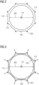
- Figure 2 is a schematic plan view of the mould membrane 100, according to examples. In the orientation of Figure 2 , the central longitudinal axis 114 of the mould membrane 100 points into the page and is represented by a cross representing the rear of an arrow to indicate direction. In these examples, the inner surface of the membrane body 104 has a circular cross section.
- the membrane body 104 is in the un-deformed state.
- the inner diameter of the membrane body 104 in the un-deformed state is indicated by the double arrow 202.
- the inner diameter 202 is less than the outer diameter of the target object 102 provided on the outer surface 106 of the carrier object 108. Accordingly, in these examples, the target object 102 provided on the outer surface 106 of the carrier object 108 does not fit in the space within the membrane body 104 (as defined by the inner diameter 202) in the un-deformed state.
- the target object 102 provided as described fits within the membrane body 104 when deformation of the membrane body 104 has occurred to increase the space therein.
- Figure 3 is a schematic plan view of the mould membrane 100 and the target object 102, according to examples.
- Figure 3 shows the target object 102 provided on the outer surface 106 of the cylindrical carrier object 108 inserted into the space within the membrane body 104 in a deformed state, according to examples.
- the target object 102 and the carrier object 108 are represented schematically as a circle labelled with numeral 102.
- the target object 102 is carried on the outer surface 106 of the carrier object 108.
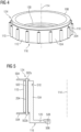
- Figure 4 is a schematic perspective view in which the target object 102 provided on the outer surface 106 of the cylindrical carrier object 108 is inserted into the space within the membrane body 104, while the membrane body 104 remains in a deformed state, according to examples.
- the outer diameter of the of the target object 102 provided on the outer surface 106 of the carrier object 108 is indicated by the double-sided arrow labelled with numeral 302.
- the membrane body 104 may be deformed to increase the space therein to accommodate the target object 102 with the larger outer diameter 302, as described below.
- the mould membrane 100 comprises a plurality of first manipulation structures 110.
- the first manipulation structures 110 are specific examples of manipulation structures that may deployed, and some other examples are described further below.
- the first manipulation structures 110 are provided on an outer part 112 of the membrane body 104.
- the outer part 112 is the outward facing surface of the cylinder defined by the cylindrical membrane body 104.
- the outer part 112 is the surface of the membrane body 104 which faces in a direction away from the central longitudinal axis 114.
- only some of the first manipulation structures 110 are labelled with a reference numeral. However, it can clearly be seen that, in these examples, there are a number of first manipulation structures 110 provided around the outer part 112. In examples, the number of the manipulation structures may vary. In some examples, there may be three or more first manipulation structures 110. For example, eight first manipulation structures 110 may be provided spread around the outer part 112.
- the first manipulation structures 110 are integral with the remainder of the membrane body 104 and comprise resiliently deformable material protruding out from the outer part 112 in a direction away from the central longitudinal axis 114.
- each of the plurality of first manipulation structures 110 are configured to be manipulated by application of mechanical force to control the space within the membrane body 104 by controlling the amount of deformation of the membrane body 104.
- the first manipulation structures 110 provide structures at which force can be applied to the membrane body 104 in order to deform the membrane body 104.
- the first manipulation structures 110 are sites where mechanical force can be applied to deform a region of the membrane body 104 local to the manipulation structure 110 in question.
- each of the first manipulation structures 110 force is applied to each of the first manipulation structures 110 in a direction perpendicular to and away from the central longitudinal axis 114 (as shown by arrows originating from each first manipulation structure 110 in Figure 3 ).
- the membrane body 104 is deformed such that the space within the membrane body 104 is increased. Creating more space within the membrane body 104 provides for the target object 102 with outer diameter 302 to be accommodated.
- the first manipulation structures 110 may take various different forms to provide for the membrane body 104 to deform in the manner described herein. Some example manipulation structures (such as the first manipulation structures 110, among other examples) are described in further below. However, those skilled in the art will appreciate that other kinds of structures to perform the described functions are possible.
- one or more of the plurality of manipulation structures comprises an elongate through hole.
- the through holes extend in a direction substantially parallel to the central longitudinal axis 114 of the cylindrical membrane body 104 in the un-deformed state.
- the first manipulation structures 110 comprise elongate through holes.
- Other examples of the manipulation structures may not comprise through holes, as described later with respect to Figures 9 to 11 .
- Figures 1 to 8 relate to examples of the first manipulation structures 110 comprising through holes.
- the first manipulation structures 110 comprises through holes 204 which are elongate as shown.
- the elongate through hole extends generally in the same direction as the central longitudinal axis 114 in the un-deformed state.
- FIG. 5 is a side cross-sectional partial view showing the first manipulation structure 110, according to examples. In the examples of Figure 5 , the cross section is taken through the through hole 204 of the first manipulation structure 110 shown.
- the through hole 204 is configured to receive an elongate manipulation member 502 such that applying a force to an end of the elongate manipulation member 502, in a direction perpendicular to the central longitudinal axis 114, causes the membrane body 104 in the vicinity of the respective first manipulation structure 110 to deform.
- a force with a non-zero component parallel to the central longitudinal axis 114 is not excluded.
- components of force in a direction perpendicular to the central longitudinal axis 114 are relevant to the deformation affecting the space within the membrane body 104. Accordingly, the present description focuses on force in a direction perpendicular to the central longitudinal axis 114.
- the elongate manipulation member 502 comprises a first manipulation member end 502a and a second manipulation member end 502b.
- the elongate manipulation member 502 is longer than the through hole 204.
- the elongate manipulation member 502 may be received in the through hole 204 such that the first manipulation member end 502a and the second manipulation member end 502b protrudes out from the through hole 204.
- each of the ends 502a, 502b is connected to an actuation mechanism 504.
- the actuation mechanism 504 is depicted simply as elements connecting to the first and second manipulation member ends 502a, 502b.
- the elongate manipulation member 502 may be provided in the form of a pin. The ends 502a, 502b of the pin may be connected to the actuation mechanism 504 using various different means, which those skilled in the art will appreciate.
- the actuation mechanism 504 may be any actuation mechanism which can be used to provide a mechanical force suitable for acting on the elongate manipulation member 502.
- the actuation mechanism may comprise an electronic actuation system (e.g., electrical motors), may be a pneumatic actuation system, may be a hydraulic system, may be a mechanical actuation system, and the like.
- the actuation mechanism 504 may include a combination of such systems.
- a mechanical system may be used to open and close the mould membrane as a whole (e.g., when creating space therein for the target object 102 and carrier object 108 to be inserted), and pneumatic actuators may be used individual manipulation structures (e.g., to manipulate local regions of the membrane body 104).
- the type of actuation mechanism used may depend on the size of the membrane body 104, amount of force required to deform the membrane body 104, and the like.
- an example of the membrane body 104 suitable for use in encapsulating magnetic coils for MRI imaging may be large and require relatively large forces to cause the desired amount of deformation.
- a hydraulic actuation system may be suitable.
- the actuation mechanism 504 may be automatically controlled.
- the actuation mechanism 504 is controlled without manual intervention from a user (other than the user input control commands into a control system of the actuation mechanism 504, for example).
- the actuation mechanism 504 is computer control in that control signal are input to the actuation mechanism 504 from the computer.
- the actuation mechanism 504 is configured to apply mechanical force to all the manipulation structures provided.
- the actuation mechanism 504 may be configured such that force is applied independently to each manipulation structure, and each manipulation structure is therefore independently controlled.
- a separate actuation mechanism is provided for each manipulation structure for independent control.
- the various manipulation structures may be controlled automatically.
- the various manipulation structures may be independently manipulated and deform local regions of the membrane body 104.
- this provides for a high level of control of the membrane body 104 and how it forms the outer mould over the target object 102.
- the automated nature of the manipulation of the membrane body 104 provides efficiency saving (for example, in terms of time and amount of work required by users) as compared to typical methods of applying flexible moulds involving manual manipulation by hand, for example. For example, avoiding manual manipulation may also provide consistently repeatable results.
- the automatic manipulation also provides for manipulation at different stages of the encapsulation process, for example, as may not be possible when manual manipulation is relied upon.
- the manipulation structures also provide for the mould membrane 100 to be removed after a moulding process to encapsulate the target object 102 has been completed.
- the mould membrane 100 may be removed in a controlled manner without significantly disturbing the encapsulated target object 102 in an undesired manner. Removal in a controlled manner may also avoid causing damage to the mould membrane, the cured substance, and/or the target object.
- the described examples of the mould membrane 100 provide for the mould membrane 100 to be reused.
- a force may be applied at each first manipulation structure 110, as shown in Figures 3 and 4 for example, to stretch the membrane body 104 so that the target object 102 provided on the carrier object 108 can be inserted into the space within the membrane body 104.
- the manipulation structures may be manipulated (for example, by reducing the force applied to the elongate manipulation members 502) to allow the membrane body 104 to contract onto the target object 102.
- due to the stretching there is a spring force urging the membrane body 104 to return to the un-deformed state.
- the force applied by the actuation means 504 in a direction away from the central axis 114 is reduced or removed to allow the membrane body 104 to contract.
- This spring force provides for a tight fit of the membrane body 104 onto the target object.
- the un-deformed inner diameter of the membrane body may be chosen such that there is an appropriate spring force to cause the membrane body 104 to form a tight fit against the desired target object 102.
- force may be applied at the first manipulation structures 110 in a direction towards the central longitudinal axis 114. Such force may aid in forming a tight fit against the desired target object 102. In some examples, a combination of force away from and towards the central longitudinal axis 114 may be used to adjust the membrane body 104, as desired.
- Providing a resilient deformable membrane for forming a tight fit is advantageous, for example, because a tight fit may be achieved independently of variations in the size of the target object 102.
- the mould membrane is intended for use with a specific outer diameter 302 for the target object 102, there may be variation in the exact outer diameter 302 depending on the procedure for providing the target object 102 on the carrier object 108.
- the target object 102 may have an outer diameter larger or smaller as compared to other instances.
- the inner diameter 202 and deformation characteristics of the membrane body 104 may be selected so as to accommodate for such variation.
- the same membrane body 104 may be used to consistently form a tight fits on a number of target objects with some variation in sizes.
- a rigid/hard outer mould would not be adaptable to such variation, the flexible mould membrane described herein may readily for tight-fitting outer moulds despite such variation in outer diameter 302.
- a given example of the reusable mould membrane 100 may be used to form a mould on target objects of different desired sizes (e.g., having various different values for the outer diameter 302 by design). This is because, the membrane body 104 deforms and then contracts onto the target object and is therefore capable of forming a tight-fitting outer mould for a range of outer diameters 302 (within reasonable ranges depending on the elasticity of the reliantly deformable material and other parameters, for example).
- the described membrane body 104 may advantageously provide a tight fit at all the relevant regions of the target object irrespective of local variations in size and shape.
- the resiliently deformable material of the membrane body 104 may reach into local gaps in the target object 102 when the membrane body 104 contract. This may be particularly advantageous in the examples of a coil wound around the carrier object 108.
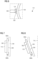
- FIG. 7 and 8 are schematic partial cross-sectional views of the first manipulation structure 110, according to examples.
- Figure 7 shows the membrane body 104 in an un-deformed state.
- the arrow 602 indicates force applied to the first manipulation member end 502a of the elongate manipulation member 502 to transition the membrane body 104 from the un-deformed state shown in Figure 7 to a deformed state as shown in Figure 8 .
- the actuation mechanism 504 is not shown for simplicity.
- the second manipulation member end 502b acts as a fulcrum and the elongate manipulation member 502 pivots to form an angle relative to the central axis 114 as shown.
- the membrane body 104 may be manipulated in the vicinity of the first manipulation structure 110 in question in various ways by differently applying mechanical force at the first manipulation member end 502a and/or the second manipulation member end 502b, depending on the application.
- one or more of the plurality of manipulation structures comprises an embedded manipulation member that is embedded within the membrane body 104.
- the manipulation structure also comprises one or more attachment structures (930) attached to the embedded manipulation member which protrude from the membrane body (104) in a direction away from the central longitudinal axis 114 of the membrane body 104embedded manipulation member.
- the manipulation structure according to such examples is different to the previously described first manipulation structure 110 in that it comprises the embedded manipulation member instead of the through hole 204 for receive the elongate manipulation member 502.
- Figure 9 is a schematic partial plan side cross-sectional view showing a second manipulation structure 910, according to examples.
- the second manipulation structure 910 is another example of a manipulation structure configured to be manipulated by application of mechanical force to control the space within the membrane body 104 by controlling the amount of deformation of the membrane body 104.
- elements which correspond to elements described with respect to the first manipulation structure 110 are labelled with the same reference numerals as in the preceding Figures.
- the outer part of the membrane body 104 may comprise a plurality of manipulation structures as described in relation to Figures 1 to 8 , or a plurality of manipulation structure as described below in relation to Figure 9 .
- the membrane body 104 may comprise a plurality of manipulation structures including one or more of the first manipulation structures as described in relation to Figures 1 to 8 and one or more of the second manipulation structures as described in relation to Figure 9 .
- manipulation structures are possible.
- manipulation structures configured to be manipulated by application of mechanical force to control the space within the membrane body 104 by controlling the amount of deformation of the membrane body 104, those skilled in the art will appreciate the various ways in which such manipulation structures may be provided.
- the second manipulation structure 910 comprises the embedded manipulation member 920, as shown in Figure 9 .
- the second manipulation structure 910 comprises one or more attachment structures 930 attached to the embedded manipulation member 920.
- the attachment structures 930 are integral with the embedded manipulation member 920.
- the attachment structures 930 and the embedded manipulation member 920 together are provided as a single piece.
- the attachment structures 930 are separate pieces which are attached onto the embedded manipulation member 920.
- the attachment structures 930 protrude from the membrane body 104 in a direction away from the central longitudinal axis 114 of the membrane body 104.
- the attachment structures 930 extend outwardly with respect to the outer part 112 of the membrane body 104.
- the attachment structures 930 are partially embedded within the material of the membrane body 104.
- any number of attachment structures 930 may be provided, as desired. In some examples, the number of attachment structures 930 may depend on the shape and/or size of the embedded manipulation member 920.
- the embedded manipulation member 920 is configured such that applying a force to the attachment features 930, in a direction perpendicular to the central longitudinal axis 114, causes the membrane body 104 in the vicinity of the second manipulation structure 910 to deform.
- the embedded manipulation member 920 may be a rigid plate (for example, comprising a metal or other material which forms a rigid plate of appropriate dimensions).
- the embedded manipulation member 920 is a rigid rectangular plate or a rigid circular plate.
- the rigid plate may be embedded in the sense that the rigid plate is moulded into the resiliently deformable material of the second manipulation structure 910.
- the plate may be oriented such that it faces substantially in the same direction as the outer part 112 (i.e., the outer surface of the membrane body 104).
- FIG. 10 is a schematic partial side cross-sectional view of the second manipulation structure 910, according to example. The horizontal dashed lines indicate that the structures continue beyond what is shown in Figure 10 .
- the embedded manipulation member 920 is a rectangular plate.
- the embedded manipulation member 920 may be partially embedded into the resiliently deformable material at the site of the second manipulation structure 910 such that two ends of the embedded manipulation member 920 protrude, as described below, for example.
- Figure 11 is a schematic partial side cross-sectional view of the second manipulation structure 910, according to examples.
- the examples of Figure 11 are different to the examples of Figures 9 and 10 in that the embedded manipulation member 920 is partially embedded.
- two ends of the embedded manipulation member 920 protrude out from the resiliently deformable material (e.g., protrude out from the remainder of the second manipulation structure 910).
- two ends of the embedded manipulation member 920 protrude out at different positions with respect to the central longitudinal axis 114 (see Figure 11 ).
- the embedded manipulation member 920 comprises a first embedded member manipulation end 920a and a second embedded member manipulation end 920b, each provided at a different end of the embedded manipulation member 920 which protrudes as described.
- the first embedded member manipulation end 920a is a top embedded member manipulation end
- the second embedded member manipulation end 920b is a bottom embedded member manipulation end.
- the embedded member manipulation ends 920a, 920b may comprise attachment structures 930.
- the attachment structures 930 are configured to engage with the actuation mechanism 504 (not shown in Figures 9 10, and 11 ), for example.
- the attachment structure 930 may be in the form of an attachment ring, an attachment through hole, an attachment threaded hole, or any other kind of structure which provides for mechanical coupling with the actuation mechanism.
- the second manipulation structure 910 may function in the same manner as described above in relation to first manipulation structure 110. Therefore, a description of common features, functions, advantages and the like is omitted for brevity.
- the described manipulation structures provide a way for mechanical force to be applied at a given site of the membrane body 104 so as to manipulate the membrane body 104 and take advantage of the elasticity of the resiliently deformable material.
- the mould membrane 100 comprises a first seal arrangement provided towards a first end of the mould membrane 100.
- the first seal arrangement is configured to form a seal against the carrier object 108.
- the first end of the mould membrane 100 is at a particular position with respect to the central axis 114.
- a second end opposite to the first end of the mould membrane 100 is a different position with respect to the central axis 114.
- first end 116 of the mould membrane 100 there is labelled the first end 116 of the mould membrane 100.
- first end 116 of the mould membrane 100 is the bottom end of the mould membrane 100.
- first seal arrangement is provided at a location where the membrane body 104 does not contact the target object 102, in use.
- the first seal arrangement may be of any form or construction which provides for a seal to be formed.
- the seal formed by the first seal arrangement is a seal preventing or significantly inhibiting flow of a liquid material out from between the mould membrane 100 and the carrier object 108.
- the seal formed by the first seal arrangement is a vacuum seal (in other word prevents/significantly inhibits flow of air/gas molecules).
- the tightness of the seal formed by the first seal arrangement may be selected according to the application. In some application, only a seal to prevent flow of liquids may be desired. In some other applications, a vacuum seal may be desired.
- the membrane body 104 comprises a flange 118 towards the first end 116.
- the flange 118 extends into the membrane body 104.
- the flange 118 extends towards the central longitudinal axis 114.
- the flange 118 is provided all the way around the cylindrical membrane body 104, as shown in Figure 1 , for example.
- the flange 118 is part of the membrane body 104 and therefore comprises the resiliently deformable material.
- the first seal arrangement is labelled with the numeral 120.
- the first seal arrangement 120 is provided on the flange 118, as is the case in the examples of Figure 1 .
- the flange may be omitted and the first seal arrangement 120 may be provided on another part of the membrane body 104.
- the membrane body 104 may have a ring like structure.
- the flange 118 may be present, but the first seal arrangement 120 may nevertheless be provided on a part of the membrane body 104 other than on the flange 118.
- the flange 118 contacts an end surface (e.g., a bottom surface) with respect to the central axis 114 of the carrier object 108. In the orientation shown in Figure 1 , the flange 118 contacts the bottom surface (not visible) of the carrier object 108.
- the first seal arrangement 120 takes the form of a channel formed in the flange 118 where the resiliently deformable material does not contact the carrier object 108.
- the channel creates a region where there is air or space between the resiliently deformable material and the carrier object 108, as compared to other regions.
- the first seal arrangement 120 is in the form of the described channel.
- the first seal arrangement 120 may extend all the way around the flange 118 so as to form a ring like channel surrounding the central axis 114.
- the first seal arrangement 120 of these examples functions to create a seal under vacuum for example.
- air within the channel forming the first seal arrangement 120 is evacuated. This causes the flange 118 to press forcefully (depending on the strength of the vacuum, the exact structure of the channel and the like) against the carrier object 108 forming a seal.
- the channel 120 of the examples of Figure 5 is provided a given distance away from where the flange 118 meets the cylindrical part of the membrane body 104.
- the given distance may be selected to ensure that the seal created by evacuating the channel is not compromised when the membrane body 104 deforms as described.
- the first seal arrangement 120 may be in the form of a channel on an inward facing surface (a surface facing the central longitudinal axis 114) of the membrane body 104, for example.
- the first seal arrangement 120 may provide other means for sealing the flange 118 (or another part of the membrane body 104, depending on the example deployed) to the carrier object 108.
- fixing mechanisms as part of the first seal arrangement 120
- the first seal arrangement 120 comprises a suitable type of mechanical clamp. These other examples of the first seal may be deployed on the flange 118 or another part of the membrane body 104, for example.
- the first seal arrangement 120 may comprise a strap which is positioned around the outer part 112 of the membrane body 104.
- the strap may function by tightening around the membrane body 104 and forcefully pressing the membrane body 104 against the carrier object 108 (in the vicinity of the strap).
- the mould membrane 100 comprises a second seal arrangement provided towards a second end of the mould membrane 100.
- the second end of the mould membrane 100 is opposite to the first end 116 of the mould membrane 100.
- the second end 124 is the top end of the mould membrane 100.
- the second seal arrangement is provided at a location where the membrane body 104 does not contact the target object 102, in use.
- FIG. 5 there is shown an example second seal arrangement 510 towards the second end 124 of the mould membrane 100.
- the described first seal arrangement 120 and the second seal arrangement 510 are positioned such that the region of the membrane body 104 which comes into contact with the target object 102 is between the first and second seal arrangements.
- seals are formed around the target object 102 in contact with the membrane body 104.
- the second seal arrangement 510 is configured to form a seal against the carrier object 108 positioned within the membrane body 104.
- the second seal arrangement 510 comprises a channel provided in the inward facing surface (the surface facing the central longitudinal axis 114) of the membrane body 104.
- the second seal arrangement 510 takes the form of a channel as previously described in relation to the first seal arrangement 120.
- the second seal arrangement 510 may comprise other means of forming a seal such as a mechanism of fixing (e.g., clamping and the like) the membrane body 104 to the carrier object 108 towards the second end 124.
- the second seal arrangement 510 comprises a suitable type of mechanical clamp.
- the second seal arrangement 510 is configured to form a seal on a surface of the carrier object 108 which is substantially perpendicular to the outer surface 106 (e.g., the top surface of the carrier object 108 in the orientations of Figures 1 , 4 and 5 ).
- the second seal arrangement 510 may comprise a strap which is positioned around the outer part 112 of the membrane body 104 and functions by tightening around the membrane body 104 to forcefully press the region of the membrane body 104 in the vicinity of the strap against the carrier object 108.
- a second seal actuation mechanism which causes the second seal arrangement 510 to apply the seal.
- the second seal actuation mechanism may be used to tighten a strap, apply a clamp and the like, depending on the construction of the second seal arrangement.
- the second seal actuation mechanism operates independently to the mechanism(s) which actuate the manipulation structures.
- the second seal actuation mechanism may be used to hold the second seal arrangement open when the membrane body 104 is stretch for insertion of the target object 102, for example.
- a pressure difference may be applied across the mould membrane 100, for example, by evacuating the volume between the mould membrane 100 and the carrier object 108, and/or applying external pressure to the mould membrane 100.
- the pressure difference may be used to cause the substance (e.g., resin) to fill the space around the target object 102.
- the pressure difference may aid in pressing the membrane body 104 to press up against the target object 102.
- a combination of evacuating the volume between the mould membrane 100 and the carrier object 108 and applying external pressure is used.
- the mould membrane 100 comprise the first seal arrangement 120.
- both the first seal arrangement 120 and the second seal arrangement 510 may be provided.
- both the first and second seal arrangements 120, 510 may be provided in a manner that vacuum seals can be created either side of the target object. Such an example may be deployed depending on the desired application.
- first and second seal arrangements 120, 510 are provided and there is no vacuum in the space immediately outside the mould membrane 100.
- this may be where the mould membrane 100 is not placed within an autoclave that is evacuated.
- means for evacuating the air e.g., tubes, pipes and the like
- means for introducing the substance e.g., resin
- the substance e.g., resin
- the mould membrane 100 may comprise a rigid base structure connected to the flange 118 towards an innermost edge of the flange 118.
- the rigid base structure may be a rigid ring.
- the rigid base structure may be a rigid disk.
- a first rigid base structure 122 in the form of a rigid disc 122 connected to the flange 118.
- a second rigid base structure 506 in the form of a rigid ring 506.
- the first and second rigid base structures 122, 506 are examples of the described rigid base structure.
- the rigid base structure 122, 506 may comprise an appropriately rigid material such as a metal and the like, for example.
- the rigid base structure 122, 506 comprises a fixing mechanism to fix the rigid base structure 122, 506 to the carrier object 108.
- the second rigid base structure 506 comprises a rigid ring fixing mechanism 508.
- the fixing mechanism of the rigid base structure 122, 506 may be provided in various forms such as a clamping mechanism, a mechanism utilising screws and/or bolts, and the like.
- the mould membrane 100 comprises a first alignment arrangement configured to engage with a second alignment arrangement such that the rotational alignment of the mould membrane about the central longitudinal axis 114 relative to the carrier object 108 is fixed.
- the first and second alignment arrangements may also aid in generally positioning (not just rotationally) the carrier and target objects as desired within the mould membrane 100.
- correct alignment may also provide correct placement of the first and/or second seal arrangements so that the seals are not disturbed during any manipulation of the membrane body 104.
- the first and second alignment arrangements may be provided to achieve such alignment.
- the mould membrane 100 comprises a first alignment arrangement 126 in the form of guide pins.
- the guide pins 126 are elongate such that they extend in a direction substantially parallel to the central longitudinal axis 114 when the membrane body 104 is in the un-deformed state. In examples where guide pins are utilised, any number of guide pins may be used.
- the guide pins may be provided in the rigid base structure 122, 506.
- the guide pins may be provided on the rigid disc 122.
- the guide pins may be provided on the rigid ring 506.
- the guide pins may be part of the membrane body 104 and may be provided on the flange 118, for example.
- the guide pins may be moulded into the resiliently deformable material which forms the flange 118.
- the carrier object 108 comprises a second alignment arrangement 128.
- the second alignment arrangement 128 is in the form of holes which receive the guide pins 126.
- the carrier object 108 comprises an inward extending flange 130 provided at a part of the carrier object 108 which contacts the flange 118. In use, the inward extending flange 130 is positioned towards the first end 116 of the mould membrane 100, in these examples.
- the second alignment arrangement 128 comprises through holes provided in the inward extending flange 130. The guide pins are received in the through holes 128 in order to align the position of the target object 102 and the membrane body 104, as desired.
- the mould membrane 100 may comprise a structure which engages with an inverse complementary structure on the carrier object 108 such that the relative rotational position between the mould membrane 100 and the carrier object 108 is fixed.
- the mould membrane 100 may comprise a structure which engages with an inverse complementary structure on the carrier object 108 such that the relative rotational position between the mould membrane 100 and the carrier object 108 is fixed.
- the relative rotational position may be fixed, given the examples described herein.
- each of the plurality of manipulation structures 110, 910 comprises manipulation structure fabric reinforcement moulded into the respective manipulation structure 110, 910.
- manipulation structure fabric reinforcement 940 comprises one or more fabric layer, for example, positioned around the embedded manipulation member 920.
- the manipulation structure fabric reinforcement is confined to the respective manipulation structure.
- Providing manipulation structure fabric reinforcement with examples of the manipulation structures may advantageously provide structural strength to said manipulation structures (for example, to avoid damage from forces applied by the actuation mechanism 504).
- providing manipulation structure fabric reinforcement with examples of the manipulation structures may provide for control of the amount of deformation which occurs at said manipulation structures.
- the fabric used may not be elastically deformable.
- Figures 9, 10 and 11 are merely specific examples of fabric reinforcement within the manipulation structures.
- the first manipulation structure 110 which also comprises fabric reinforcement.
- fabric reinforcement may be provided in one or more layer to surround the elongate through hole 204. Any configuration and/or number of fabric reinforcement layers may be provided as part of examples of the manipulation structure, according to the desired amount of reinforcement.
- the membrane body 104 comprises membrane body fabric reinforcement to restrict the amount of deformation of the membrane body 104.
- Figure 12 is a schematic plan cross-sectional partial view of the mould membrane 100 comprising membrane body fabric reinforcement 1202.
- the membrane body fabric reinforcement 1202 comprises one or more continuous layers of fibric which surround the central longitudinal axis 114.
- the membrane body fabric reinforcement 1202 may extend the whole or part of the length of the membrane body 104 in a direction along the central longitudinal axis 114.
- the membrane body fabric reinforcement 1202 may be used to restrict the amount by which the membrane body 104 can be deformed to create space therein and away from the central longitudinal axis 114.
- both the first and second seal arrangements may be provided where a vacuum between the membrane body 104 and the carrier object 108 is desired.
- the whole mould membrane may be placed within a chamber which is under vacuum (such as an autoclave, for example).
- the second seal arrangement may be omitted.
- the first seal arrangement may create a seal tight enough to significantly inhibit or prevent flow of the substance for encapsulation, but not necessarily tight enough to be vacuum tight.
- the mould membrane comprises a reservoir structure provided towards the second end 124 of the mould membrane.
- the reservoir structure is for introducing the substance for encapsulation.
- Figure 13 is a schematic perspective view of the mould membrane 100, according to examples. In the examples of Figure 13 , a different example of the mould membrane 100 is shown than in the preceding Figures. In the examples of Figure 13 , the mould membrane 100 is similar to that described with respect to Figures 1 to 8 and may comprise any combination of the previously described features.
- the mould membrane 100 of Figure 13 may comprise a plurality of the described first manipulation structures 110, a plurality of the described second manipulation structures 910, or a combination thereof. In the examples shown in Figure 13 , a plurality of the first manipulation structures 110 are provided, according to examples.
- the mould membrane 100 has a greater dimension with respect to the central longitudinal axis 114 as compared to the previously described mould membrane examples.
- the dimensions of the mould membrane may be selected according to the desired application.
- an example target object 102 provided on a carrier object 108 with an outer surface 106 different from the previously described target and carrier objects in their dimensions along the central longitudinal axis 114, as mere examples.
- the mould membrane 100 of these examples is for use in encapsulating a coil which corresponds to a cylinder of greater length, for example.
- the examples of Figure 13 illustrate example dimensions different to the examples described previously.
- the mould membrane 100 comprises a reservoir structure 1302.
- the reservoir structure 1302 forms a funnel like receptacle in which a desired quantity of the substance can be held.
- the reservoir structure 1302 extends all the way around, with respect to the central longitudinal axis 114, at the second end 124.
- the mould membrane 100 may be placed within a vacuum chamber.
- the carrier object 108 carrying the target object 302 may be positioned within the membrane body 104.
- air between the membrane body 104 and the carrier object 108 is removed, and the substance held in the reservoir structure 1302 is drawn into the space left behind. In this manner, the entirety of the target object 102 may be covered in the desired substance.
- Automated manipulation of the membrane body 104 may be particularly advantageously in applications where the encapsulating process takes place inside of a closed chamber such as an autoclave. This is because manual manipulation is not possible once the typical mould is placed within a vacuum chamber. However, because the described examples provide a way to automate the manipulation using actuation mechanism(s), manipulation can take place inside a vacuum chamber. This provides for additional adjustment of the outer mould during various processes which take place inside the vacuum chamber.
- the outer surface of the carrier object corresponds to the outer surface of a plain cylinder.
- the carrier object may comprise one or more flanges or protrusions which extend away from the central longitudinal axis 114, when the carrier object is positioned within the mould membrane as described.
- the carrier object may have a shape similar to that of a bobbin and the like.
- Figure 17 is a schematic perspective cross-sectional view of the mould membrane 100 forming an outer mould on the target object 102, according to examples.
- the target object is carried on the carrier object 108, which comprises flanges as shown in Figure 17 .
- the membrane body 104 contracts onto the target object 102 so as to form a tight-fitting outer mould.
- the example mould membrane for use with that carrier object has a membrane shaped appropriately such that a tight-fitting outer mould can be formed onto the target object.
- the mould membrane according to any of the described examples may be used in a method for use during a process to encapsulate the target object in the substance.
- the mould membrane 100 may be used in any orientation as desired.
- Figure 15 is a schematic perspective view of an example mould membrane 100 which is oriented horizontal with respect to the ground.
- Figure 16 is a schematic perspective view of an example mould membrane 100 which is oriented such that the positions of the first and second ends of the mould membrane 100 are swapped.
- the mould membrane 100 of Figure 16 is upside down.
- the mould membrane 100 may be lowered onto the carrier object.
- the presence of the first and second seal arrangements may provide for any orientation to be used.
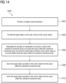
- Figure 14 is a flow diagram illustrating a method 1400 for use during a process to encapsulate the target object, according to examples. More specifically, the method 1400 involves forming a tight-fitting outer mould during around the target. In the following description of the method 1400, reference is made to the examples described previously.
- a reusable mould membrane is provided to form the outer mould.
- the reusable mould membrane is a mould membrane according to any of the examples described herein.
- the target object 102 is provided on the outer surface of the carrier object 108.
- the manipulation structures 110, 910 are manipulated to deform the cylindrical membrane body 104 such that the target object 102 provided on the carrier object is accommodated inside the space within the cylindrical membrane body 104.
- the manipulation structures 110, 910 are used to manipulate the membrane body 104 by deforming it.
- the manipulation structures 110, 910 are sites where mechanical force can be applied to deform a region of the membrane body 104 local to the manipulation structure 110, 910 in question.
- a mechanical force is applied at each manipulation structure 110, 910 in a direction away from the central longitudinal axis 114 to deform the membrane body 104 and create space therein, or in a direction towards the central longitudinal axis 114 to push the membrane body 104 towards the central longitudinal axis 114.
- the target object 102 provided on the carrier object 108 is inserted into the space within the cylindrical membrane body 104.
- the target object 102 carried on the carrier object 108 is inserted into the space created by manipulating the membrane body 104 at method 1406.
- Figure 13 shows the target object 102 partially inserted into the membrane body 104.
- the target object is within the membrane body such that the target object is at a position where the membrane body can contract onto the target object forming a tight-fitting outer mould.
- the examples of Figure 4 show that the target object 102 (not visible in Figure 4 ) is entirely within the cylindrical membrane body 104. It will be appreciated that it will be desired that the membrane body 104 cover the target object 102 entirely so as to form an effective tight-fitting outer mould.
- the manipulation structures 110, 910 are manipulated to allow the membrane body 104 to contract onto the target object 102 such that a tight-fitting outer mould is formed on the target object 102.
- the forces applied at the manipulation structures 110, 910 away from the central longitudinal axis 114 to create space may be relieved to allow the membrane body 104 to contract.
- the membrane body 104 contracts onto the target object 102.
- the membrane body 104 fits tightly by matching the surface variations on the target object 102.
- due to the tight fit spaces where excess amounts of the substance may pool are avoided.
- the membrane body 104 creates an outer mould with a tight fit such that a coating of the substance with relatively consistent thickness on all surfaces of the target object 102 is likely to be achieved.
- the method 1400 also comprises manipulating a given manipulation structure 110, 910 to adjust the outer mould on the target object 102 in the vicinity of the given manipulation structure 110, 910.
- the manipulation structures 110, 910 provide for mechanical force to be applied to the membrane body 104 by use of a machine (e.g., actuation mechanism 504, as opposed to manually manipulating the membrane body 104 by hand, for example).
- manipulation of the membrane body 104 may be controlled in an automated manner (e.g., using computer-controlled actuation mechanisms).
- individual manipulation structures may be used to locally manipulate the membrane body 104. In this manner, the outer mould may be locally adjusted, as desired.
- use of the mould membrane and methods described herein provide for a more efficient way to apply an outer mould onto the target object 102.
- the method 1400 provides a tight-fitting outer mould for the target object 102.
- the method 1400 may comprise further processes relating to encapsulating the target object in the substance.
- the method 1400 may comprise introducing the substance (e.g., a resin) between the outer mould formed by the mould membrane 100 and the inner mould formed by the carrier object 108.
- the method 1400 may further comprise applying a vacuum to seal the mould membrane 100 to the carrier object such that the target object 102 is sealed between the mould membrane 100 and the carrier object 108.
- the vacuum may either be applied between the mould membrane 100 and the carrier object 108 or the mould membrane 100 and carrier object may be placed within an evacuated chamber such as an autoclave.
- the target object 102 may be encapsulated in a uniform manner and so that regions of excess substance are avoided.
- manipulation structures 110, 910 may be used in order to extract the mould membrane 100 away from the encapsulated target object 102 at the end of the process. This occurs, for example in an automated and controlled manner, as previously described.
Landscapes
- Engineering & Computer Science (AREA)
- Mechanical Engineering (AREA)
- Power Engineering (AREA)
- Manufacturing & Machinery (AREA)
- Apparatus Associated With Microorganisms And Enzymes (AREA)
- Moulds For Moulding Plastics Or The Like (AREA)
- Casting Or Compression Moulding Of Plastics Or The Like (AREA)
Abstract
Description
- The present application relates to a membrane for use in moulding and a method for use during a process to encapsulate a target object.
- Various techniques may be used in order to mould an object. In some examples, hard mould tools may be used. For example, a mould tool defining an internal space which provides the desired shape for the object to be moulded may be used. In some examples, moulding techniques may be used in order to coat or encapsulate a target object in a substance, such as a resin, for example. For these applications, it may be desired that the mould tool forms a tight fit around the target object.
- In some examples, a part of the mould tool may be made of a flexible material to achieve a tight fit. For example, the target object may be provided on a rigid surface. The rigid surface may provide a platform for the moulding process. A flexible material may then be deployed to fit tightly onto, and match the shape of the target object. However, those skilled in the art will appreciate that a tight fit matching the shape of the target object may be difficult to achieve and/or deploying the flexible material may be labour intensive, require large amounts of time, and/or may have to be done manually. The flexible material may be difficult to extract without affecting the substance encapsulating the target object. Typically, the flexible material is discarded after the process to encapsulate.
- An object of the present application is to provide convenient and efficient structures and methods for moulding to encapsulate a target object in a substance.
- According to a first aspect of the present invention, there is provided reusable mould membrane for forming an outer mould during a process to encapsulate a target object in a substance, the mould membrane comprising: a cylindrical membrane body comprising a resiliently deformable material, wherein an inner diameter of the cylindrical membrane body is less than an outer diameter of the target object provided on an outer surface of a cylindrical carrier object, when the membrane body is in an un-deformed state; and a plurality of manipulation structures provided on an outer part of the membrane body, each of the plurality of manipulation structures configured to be manipulated by application of mechanical force to control the space within the membrane body by controlling the amount of deformation of the membrane body.
- Optionally, one or more of the plurality of manipulation structures comprises an elongate through hole; and the elongate through hole is configured to receive an elongate manipulation member such that applying a force to an end of the elongate manipulation member, in a direction perpendicular to the central longitudinal axis, causes the membrane body in the vicinity of the respective manipulation structure to deform.
- Optionally, one or more of the plurality of manipulation structures comprises: an embedded manipulation member that is embedded within the membrane body; one or more attachment structures attached to the embedded manipulation member which protrude from the membrane body in a direction away from a central longitudinal axis of the membrane body.
- Optionally, each of the one or more of the plurality of manipulation structures comprising the embedded manipulation member is configured such that applying a force to the one or more attachment features of the respective embedded manipulation member, in a direction perpendicular to the central longitudinal axis, causes the membrane body in the vicinity of the respective manipulation structure to deform.
- Optionally, the mould membrane comprises a first seal arrangement provided towards a first end of the mould membrane, the first seal arrangement configured to form a seal against the carrier object positioned within the membrane body.
- Optionally, the mould membrane comprises a second seal arrangement provided towards a second end of the mould membrane, the second seal structure configured to form a seal against the carrier object positioned within the membrane body.
- Optionally, the membrane body comprises a flange towards the first end, wherein the flange extends inwards into the membrane body; and the first seal arrangement is provided on the flange.
- Optionally, the mould membrane comprises a rigid base structure connected to the flange towards an innermost edge of the flange.
- Optionally, the mould membrane comprises a first alignment arrangement configured to engage with a second alignment arrangement such that the rotational alignment of the mould membrane about the central longitudinal axis relative to the carrier object is fixed.
- Optionally, the mould membrane comprises a reservoir structure provided towards a second end of the mould membrane for introducing the substance for encapsulation.
- Optionally, each of the plurality of manipulation structures comprises manipulation structure fabric reinforcement moulded into the respective manipulation structure.
- Optionally, the membrane body comprises membrane body fabric reinforcement to restrict the amount of deformation of the membrane body.
- According to a second aspect of the present invention, there is provided a method for use during a process to encapsulate a target object in a substance, the method comprising: using a reusable mould membrane to form the outer mould. The reusable mould membrane comprises: a cylindrical membrane body comprising a resiliently deformable material, wherein the inner diameter of the cylindrical membrane body is less than the outer diameter of the target object provided on an outer surface of a cylindrical carrier object, when the membrane body is in an un-deformed state; and a plurality of manipulation structures provided on an outer part of the membrane body, each of the plurality of manipulation structures configured to be manipulated by application of mechanical force to control the space within the membrane body by controlling the amount of deformation of the membrane body. The method comprises: providing the target object on the outer surface of the carrier object; manipulating the plurality of manipulation structures to deform the cylindrical membrane body to increase the space within the cylindrical membrane body such that the target object provided on the carrier object is accommodated inside the space within the cylindrical membrane body; inserting the target object provided on the carrier object into the space within the cylindrical membrane body; manipulating the plurality of manipulation structures to allow the membrane body to contract onto the target object such that a tight-fitting outer mould is formed on the target object.
- Optionally, the method according to the second aspect comprises manipulating a given manipulation structure of the plurality of manipulation structures to adjust the outer mould on the target object in the vicinity of the given manipulation structure.
- Optionally, the method according to the second aspect comprises introducing the substance between the outer mould formed by the mould membrane and an inner mould formed by the carrier object; and applying a vacuum to seal the mould membrane to the carrier object such that the target object is sealed between the mould membrane and the carrier object.
- Examples relating to the present invention will now be described with reference to the accompanying drawings, in which:
-
Figure 1 is a first schematic perspective view of a reusable mould membrane, according to a first set of examples. -
Figure 2 is a schematic plan view of the reusable mould membrane according to the first set of examples in a first state, according to examples; -
Figure 3 is a schematic plan view of the reusable mould membrane of the first set of examples in a second state, according to examples; -
Figure 4 is a second schematic perspective view of the reusable mould membrane, according to the first set of examples; -
Figure 5 is a first side cross-sectional partial view showing the first manipulation structure, according to examples; -
Figure 6 is a schematic partial plan view of the first manipulation structure, according to examples; -
Figure 7 is a second side cross-sectional partial view showing the first manipulation structure, according to examples; -
Figure 8 is a third side cross-sectional partial view showing the first manipulation structure, according to examples; -
Figure 9 is a schematic partial side cross-sectional view of a second manipulation structure, according to a first set of examples; -
Figure 10 is a first schematic partial front cross-sectional view of the second manipulation structure, according to the first set of examples; -
Figure 11 is a second schematic partial plan cross-sectional view of the second manipulation structure, according to a second set of examples; -
Figure 12 is a schematic partial plan cross-sectional view of the reusable mould membrane of the first set of examples, according to examples; -
Figure 13 is a schematic perspective view of the reusable mould membrane, according to a second set of examples; -
Figure 14 is a flow diagram illustrating a method for use during a process to encapsulate a target object; -
Figure 15 is a schematic perspective view of the reusable mould membrane, according to a third set of examples; -
Figure 16 is a schematic perspective view of the reusable mould membrane, according to a fourth set of examples; and -
Figure 17 is a schematic perspective cross-sectional view of the reusable mould membrane, according to a fifth set of examples. - The present application relates to a reusable mould membrane. The reusable mould membrane is, for example, reusable such that it may be deployed for multiple instances of a moulding process for which the reusable mould membrane is intended.
- Referring to the accompanying Figures, in examples, there is provided a
reusable mould membrane 100 for forming an outer mould during a process to encapsulate atarget object 102 in a substance. Themould membrane 100 comprises acylindrical membrane body 104. The cylindrical membrane body 104 (hereafter often referred to as the membrane body, for brevity) comprises a resiliently deformable material, wherein theinner diameter 202 of thecylindrical membrane body 104 is less than theouter diameter 302 of the target object provided on anouter surface 106 of acylindrical carrier object 108, when themembrane body 104 is in an un-deformed state. In examples, the mould membrane also comprises a plurality ofmanipulation structures outer part 112 of themembrane body 104, each of the plurality ofmanipulation structures membrane body 104 by controlling the amount of deformation of themembrane body 104. -
Figures 1 to 13 , and15 to 17 illustrate specific examples of themould membrane 100 with various different examples of features shown. However, themould membrane 100 includes examples which provide the above-described features and is not limited only to the specific examples shown in the Figures and discussed below. Those skilled in the art will appreciate the various other ways in which the above-described features may specifically be deployed. It should be noted that for simplicity of illustrations, not all features may be shown and/or labelled in each of the Figures. Instead, the Figures are of a simplified schematic nature, and certain Figures may be used to illustrate specific examples of features. -
Figure 1 is a schematic perspective view showing areusable mould membrane 100, according to examples. In these examples, thereusable mould membrane 100 is for forming an outer mould during a process to encapsulate atarget object 102. In these examples, thetarget object 102 is provided on anouter surface 106 of acylindrical carrier object 108. For example, thecylindrical carrier object 108 acts as an inner mould during the encapsulation process. In examples, the encapsulation process is, for example, a moulding process in which the substance is moulded between the inner and outer moulds, and on the surfaces of thetarget object 102 to encapsulate thetarget object 102. For example, the encapsulation process may comprise fitting of the outer mould onto thetarget object 102, introducing the substance to coat thetarget object 102 and curing processes to cure the substance onto thetarget object 102, for example. - The
outer surface 106 of thecarrier object 108 is, for example, the outward facing surface of the cylinder defined by thecylindrical carrier object 108. In other words, theouter surface 106 is a surface of thecarrier object 108 which faces in a direction away from a central longitudinal axis of thecylindrical carrier object 108. It should be noted that when the carrier object is inserted into the mould membrane, the central longitudinal axes of the carrier object and the mould membrane are more or less aligned. Therefore, reference may be made herein in relation to position and direction of elements of the carrier object with respect to the centrallongitudinal axis 114 of the mould membrane. - The target object may be any kind of object which can be placed on the
cylindrical carrier object 108 for encapsulation via a moulding process. In some examples, the target object is a coil for use as a magnet, and is wrapped around thecylindrical carrier object 108. In some examples, the target object is a coil for the rotor windings of a motor or a generator. - The substance in which the
target object 102 is to be encapsulated may be resin for example. For example, a thermoset resin such as polyester, polyurethane, vinyl ester or epoxy may be used. For example, it may be desired to encapsulate a coil for use as a magnet in a resin, depending on the application. In some examples, the coil being encapsulated may be large, for example, of a size appropriate for use in magnetic resonance imaging (MRI). In other examples, thereusable mould membrane 100 may be used as an outer mould in relation to other target objects. For example, examples of the mould membrane disclosed herein may be used in relation to any target object which may be provided on a cylindrical carrier object and where a tight-fitting outer mould is desired. - It may be desired to provide a coating of the substance on the target object with relatively consistent thickness while avoiding substance rich areas. In the examples involving resin encapsulating a coil, it may be desired that the coating of resin on such a coil is consistent, and resin rich areas are avoided. For example, resin rich areas may be areas with more resin is present than on other areas of the surfaces of the
target object 102. For example, it may be desired that the coating from the encapsulation process has a relatively consistent thickness on all surfaces of the target object 102 (within acceptable/realistic tolerances). For example, when the coil is energised to provide a magnetic field, resin rich areas may crack and/or may take energy away from the coil. This may be undesirable and impact on the application for which the coil is being used. Also, for example, providing a relatively consistent thickness of coating while avoiding substance rich areas may reduce consumption of the substance. The consumption reduction may be large, depending on the application. Also, for example, avoiding substance rich areas may eliminate the need to remove excess substance from the encapsulated target object after curing and correspondingly reduce time taken for completing the encapsulation process. - In order to achieve a consistent coating of the substance (e.g., the resin) on the target object 102 (e.g., the coil) while avoiding substance rich areas, it may be desired that the mould being used is tightly fitted onto the target object. The described examples advantageously provide for a tight-fitting outer mould.
- The term "cylindrical" is used herein. In terms of cross section, the elements described as cylindrical may have a circular cross section. However, the cross section is not so limited. In some examples, the cross section may be an ellipse. For examples, the cross section taken perpendicular to the central longitudinal axis of the cylinder being described may be an ellipse. As referred to herein, a cylinder with a circular cross section is taken as a special case of a general cylinder which is not limited to a circular cross section.
- In some examples, the
membrane body 104 is an open cylinder. In some examples, themembrane body 104 comprises one or more flanges, as described further below. In the described examples, themembrane body 104 comprises a resiliently deformable material. For example, themembrane body 104 may comprise an elastomer such as silicone, and the like. In some examples, themembrane body 104 may comprise latex, a nitrile rubber, polyurethane or vinyl.Figure 2 is a schematic plan view of themould membrane 100, according to examples. In the orientation ofFigure 2 , the centrallongitudinal axis 114 of themould membrane 100 points into the page and is represented by a cross representing the rear of an arrow to indicate direction. In these examples, the inner surface of themembrane body 104 has a circular cross section. In the examples ofFigure 2 , themembrane body 104 is in the un-deformed state. The inner diameter of themembrane body 104 in the un-deformed state is indicated by thedouble arrow 202. In these examples, theinner diameter 202 is less than the outer diameter of thetarget object 102 provided on theouter surface 106 of thecarrier object 108. Accordingly, in these examples, thetarget object 102 provided on theouter surface 106 of thecarrier object 108 does not fit in the space within the membrane body 104 (as defined by the inner diameter 202) in the un-deformed state. For example, thetarget object 102 provided as described fits within themembrane body 104 when deformation of themembrane body 104 has occurred to increase the space therein. -
Figure 3 is a schematic plan view of themould membrane 100 and thetarget object 102, according to examples.Figure 3 shows thetarget object 102 provided on theouter surface 106 of thecylindrical carrier object 108 inserted into the space within themembrane body 104 in a deformed state, according to examples. For simplicity, inFigure 3 , thetarget object 102 and thecarrier object 108 are represented schematically as a circle labelled withnumeral 102. However, it will be appreciated that thetarget object 102 is carried on theouter surface 106 of thecarrier object 108.Figure 4 is a schematic perspective view in which thetarget object 102 provided on theouter surface 106 of thecylindrical carrier object 108 is inserted into the space within themembrane body 104, while themembrane body 104 remains in a deformed state, according to examples. - The outer diameter of the of the
target object 102 provided on theouter surface 106 of thecarrier object 108 is indicated by the double-sided arrow labelled withnumeral 302. For example, themembrane body 104 may be deformed to increase the space therein to accommodate thetarget object 102 with the largerouter diameter 302, as described below. - In these examples, the
mould membrane 100 comprises a plurality offirst manipulation structures 110. Thefirst manipulation structures 110 are specific examples of manipulation structures that may deployed, and some other examples are described further below. Thefirst manipulation structures 110 are provided on anouter part 112 of themembrane body 104. For example, theouter part 112 is the outward facing surface of the cylinder defined by thecylindrical membrane body 104. In other words, theouter part 112 is the surface of themembrane body 104 which faces in a direction away from the centrallongitudinal axis 114. In the Figures, only some of thefirst manipulation structures 110 are labelled with a reference numeral. However, it can clearly be seen that, in these examples, there are a number offirst manipulation structures 110 provided around theouter part 112. In examples, the number of the manipulation structures may vary. In some examples, there may be three or morefirst manipulation structures 110. For example, eightfirst manipulation structures 110 may be provided spread around theouter part 112. - The
first manipulation structures 110 are integral with the remainder of themembrane body 104 and comprise resiliently deformable material protruding out from theouter part 112 in a direction away from the centrallongitudinal axis 114. - In examples, each of the plurality of
first manipulation structures 110 are configured to be manipulated by application of mechanical force to control the space within themembrane body 104 by controlling the amount of deformation of themembrane body 104. For example, thefirst manipulation structures 110 provide structures at which force can be applied to themembrane body 104 in order to deform themembrane body 104. For example, thefirst manipulation structures 110 are sites where mechanical force can be applied to deform a region of themembrane body 104 local to themanipulation structure 110 in question. - Referring to the examples shown in
Figure 3 , in these examples, force is applied to each of thefirst manipulation structures 110 in a direction perpendicular to and away from the central longitudinal axis 114 (as shown by arrows originating from eachfirst manipulation structure 110 inFigure 3 ). As a result of the force applied to each of thefirst manipulation structures 110, themembrane body 104 is deformed such that the space within themembrane body 104 is increased. Creating more space within themembrane body 104 provides for thetarget object 102 withouter diameter 302 to be accommodated. - The
first manipulation structures 110 may take various different forms to provide for themembrane body 104 to deform in the manner described herein. Some example manipulation structures (such as thefirst manipulation structures 110, among other examples) are described in further below. However, those skilled in the art will appreciate that other kinds of structures to perform the described functions are possible. - In some examples, one or more of the plurality of manipulation structures comprises an elongate through hole. In the examples of through holes shown in the figures, the through holes extend in a direction substantially parallel to the central
longitudinal axis 114 of thecylindrical membrane body 104 in the un-deformed state. For example, thefirst manipulation structures 110 comprise elongate through holes. Other examples of the manipulation structures may not comprise through holes, as described later with respect toFigures 9 to 11 .
Figures 1 to 8 relate to examples of thefirst manipulation structures 110 comprising through holes. In these examples, thefirst manipulation structures 110 comprises throughholes 204 which are elongate as shown. In other words, in these examples, the elongate through hole extends generally in the same direction as the centrallongitudinal axis 114 in the un-deformed state. It will be appreciated that, as used herein, "substantially parallel" does not require the elongate through holes to be precisely parallel, but covers the elongate through holes extending generally (e.g., somewhat) in the same direction as the centrallongitudinal axis 114. In other examples, not all of the manipulation structures of themould membrane 100 may be thefirst manipulation structures 110 comprising the described through holes.
Figure 5 is a side cross-sectional partial view showing thefirst manipulation structure 110, according to examples. In the examples ofFigure 5 , the cross section is taken through the throughhole 204 of thefirst manipulation structure 110 shown. - In some such examples, the through
hole 204 is configured to receive anelongate manipulation member 502 such that applying a force to an end of theelongate manipulation member 502, in a direction perpendicular to the centrallongitudinal axis 114, causes themembrane body 104 in the vicinity of the respectivefirst manipulation structure 110 to deform. It should be noted that the application of a force with a non-zero component parallel to the centrallongitudinal axis 114 is not excluded. During use as described herein, components of force in a direction perpendicular to the centrallongitudinal axis 114 are relevant to the deformation affecting the space within themembrane body 104. Accordingly, the present description focuses on force in a direction perpendicular to the centrallongitudinal axis 114. - In the examples of
Figure 5 , theelongate manipulation member 502 comprises a firstmanipulation member end 502a and a secondmanipulation member end 502b. In these examples, theelongate manipulation member 502 is longer than the throughhole 204. For example, theelongate manipulation member 502 may be received in the throughhole 204 such that the firstmanipulation member end 502a and the secondmanipulation member end 502b protrudes out from the throughhole 204. In these examples, each of theends actuation mechanism 504. For simplicity, theactuation mechanism 504 is depicted simply as elements connecting to the first and second manipulation member ends 502a, 502b. For example, theelongate manipulation member 502 may be provided in the form of a pin. Theends actuation mechanism 504 using various different means, which those skilled in the art will appreciate. - The
actuation mechanism 504 may be any actuation mechanism which can be used to provide a mechanical force suitable for acting on theelongate manipulation member 502. For example, the actuation mechanism may comprise an electronic actuation system (e.g., electrical motors), may be a pneumatic actuation system, may be a hydraulic system, may be a mechanical actuation system, and the like. In some examples, theactuation mechanism 504 may include a combination of such systems. For example, a mechanical system may be used to open and close the mould membrane as a whole (e.g., when creating space therein for thetarget object 102 andcarrier object 108 to be inserted), and pneumatic actuators may be used individual manipulation structures (e.g., to manipulate local regions of the membrane body 104). It will be appreciated that the type of actuation mechanism used may depend on the size of themembrane body 104, amount of force required to deform themembrane body 104, and the like. For example, an example of themembrane body 104 suitable for use in encapsulating magnetic coils for MRI imaging may be large and require relatively large forces to cause the desired amount of deformation. In some such examples, a hydraulic actuation system may be suitable. - The
actuation mechanism 504 may be automatically controlled. For example, theactuation mechanism 504 is controlled without manual intervention from a user (other than the user input control commands into a control system of theactuation mechanism 504, for example). For example, theactuation mechanism 504 is computer control in that control signal are input to theactuation mechanism 504 from the computer. In some examples, theactuation mechanism 504 is configured to apply mechanical force to all the manipulation structures provided. In such examples, theactuation mechanism 504 may be configured such that force is applied independently to each manipulation structure, and each manipulation structure is therefore independently controlled. In some examples, a separate actuation mechanism is provided for each manipulation structure for independent control. - Accordingly, the various manipulation structures may be controlled automatically. The various manipulation structures may be independently manipulated and deform local regions of the
membrane body 104. Advantageously, this provides for a high level of control of themembrane body 104 and how it forms the outer mould over thetarget object 102. Furthermore, the automated nature of the manipulation of themembrane body 104 provides efficiency saving (for example, in terms of time and amount of work required by users) as compared to typical methods of applying flexible moulds involving manual manipulation by hand, for example. For example, avoiding manual manipulation may also provide consistently repeatable results. The automatic manipulation also provides for manipulation at different stages of the encapsulation process, for example, as may not be possible when manual manipulation is relied upon. For example, automatic manipulation using the manipulation structures may be utilized inside of a chamber (e.g., an autoclave) where manual manipulation is not possible. The manipulation structures also provide for themould membrane 100 to be removed after a moulding process to encapsulate thetarget object 102 has been completed. For example, due to the controlled manipulation provided by the describedmould membrane 100, themould membrane 100 may be removed in a controlled manner without significantly disturbing the encapsulatedtarget object 102 in an undesired manner. Removal in a controlled manner may also avoid causing damage to the mould membrane, the cured substance, and/or the target object. The described examples of themould membrane 100 provide for themould membrane 100 to be reused. - Returning to the examples of the
first manipulation structures 110, in these examples, applying a force to eachend elongate manipulation member 502 in a direction perpendicular to thecentral axis 114 and away from thecentral axis 114 causes themembrane body 104 to deform in such a way that more space is created within themembrane body 104. For example, parts of themembrane body 104 close to thefirst manipulation structure 110 in question deform when theelongate manipulation member 502 pulls thefirst manipulation structure 110 away from thecentral axis 114. For example, seeFigures 3 and4 . In the orientation ofFigure 5 , the central axis is positioned to the right of thefirst manipulation structure 110. - In these examples, a force may be applied at each
first manipulation structure 110, as shown inFigures 3 and4 for example, to stretch themembrane body 104 so that thetarget object 102 provided on thecarrier object 108 can be inserted into the space within themembrane body 104. Once thetarget object 102 is positioned within themembrane body 104 as desired, the manipulation structures may be manipulated (for example, by reducing the force applied to the elongate manipulation members 502) to allow themembrane body 104 to contract onto thetarget object 102. In these examples, due to the stretching, there is a spring force urging themembrane body 104 to return to the un-deformed state. For example, the force applied by the actuation means 504 in a direction away from thecentral axis 114 is reduced or removed to allow themembrane body 104 to contract. This spring force provides for a tight fit of themembrane body 104 onto the target object. In examples, the un-deformed inner diameter of the membrane body may be chosen such that there is an appropriate spring force to cause themembrane body 104 to form a tight fit against the desiredtarget object 102. - In some examples, force may be applied at the
first manipulation structures 110 in a direction towards the centrallongitudinal axis 114. Such force may aid in forming a tight fit against the desiredtarget object 102. In some examples, a combination of force away from and towards the centrallongitudinal axis 114 may be used to adjust themembrane body 104, as desired. - Providing a resilient deformable membrane for forming a tight fit is advantageous, for example, because a tight fit may be achieved independently of variations in the size of the
target object 102. For example, even if the mould membrane is intended for use with a specificouter diameter 302 for thetarget object 102, there may be variation in the exactouter diameter 302 depending on the procedure for providing thetarget object 102 on thecarrier object 108. For example, in some instances, thetarget object 102 may have an outer diameter larger or smaller as compared to other instances. In the examples where thetarget object 102 is a coil, each time a coil is wrapped around a carrier object, there may be some variation in the outer diameter. However, theinner diameter 202 and deformation characteristics of themembrane body 104 may be selected so as to accommodate for such variation. In this manner, thesame membrane body 104 may be used to consistently form a tight fits on a number of target objects with some variation in sizes. Whereas a rigid/hard outer mould would not be adaptable to such variation, the flexible mould membrane described herein may readily for tight-fitting outer moulds despite such variation inouter diameter 302. - In some examples, a given example of the
reusable mould membrane 100 may be used to form a mould on target objects of different desired sizes (e.g., having various different values for theouter diameter 302 by design). This is because, themembrane body 104 deforms and then contracts onto the target object and is therefore capable of forming a tight-fitting outer mould for a range of outer diameters 302 (within reasonable ranges depending on the elasticity of the reliantly deformable material and other parameters, for example). - Additionally, the described
membrane body 104 may advantageously provide a tight fit at all the relevant regions of the target object irrespective of local variations in size and shape. For example, the resiliently deformable material of themembrane body 104 may reach into local gaps in thetarget object 102 when themembrane body 104 contract. This may be particularly advantageous in the examples of a coil wound around thecarrier object 108. - The above are examples of advantages among the various advantages of the described examples.
- Returning to the examples of
Figure 5 , in some examples, force may be applied differently to one end of theelongate manipulation member 502 compared to the other end. For example, more force may be applied by theactuation mechanism 504 to the firstmanipulation member end 502a as compared to the secondmanipulation member end 502b.Figure 7 and 8 are schematic partial cross-sectional views of thefirst manipulation structure 110, according to examples.Figure 7 shows themembrane body 104 in an un-deformed state. The arrow 602 indicates force applied to the firstmanipulation member end 502a of theelongate manipulation member 502 to transition themembrane body 104 from the un-deformed state shown inFigure 7 to a deformed state as shown inFigure 8 . In these examples, theactuation mechanism 504 is not shown for simplicity. In these examples, no force is applied at the secondmanipulation member end 502b of theelongate manipulation member 502. Accordingly, in these examples, the secondmanipulation member end 502b acts as a fulcrum and theelongate manipulation member 502 pivots to form an angle relative to thecentral axis 114 as shown. This is an example of another manner in which themembrane body 104 may be manipulated. Those skilled in the art will appreciate that themembrane body 104 may be manipulated in the vicinity of thefirst manipulation structure 110 in question in various ways by differently applying mechanical force at the firstmanipulation member end 502a and/or the secondmanipulation member end 502b, depending on the application. - In some examples, one or more of the plurality of manipulation structures comprises an embedded manipulation member that is embedded within the
membrane body 104. In such examples, the manipulation structure also comprises one or more attachment structures (930) attached to the embedded manipulation member which protrude from the membrane body (104) in a direction away from the centrallongitudinal axis 114 of the membrane body 104embedded manipulation member. The manipulation structure according to such examples is different to the previously describedfirst manipulation structure 110 in that it comprises the embedded manipulation member instead of the throughhole 204 for receive theelongate manipulation member 502. -
Figure 9 is a schematic partial plan side cross-sectional view showing asecond manipulation structure 910, according to examples. Thesecond manipulation structure 910 is another example of a manipulation structure configured to be manipulated by application of mechanical force to control the space within themembrane body 104 by controlling the amount of deformation of themembrane body 104. InFigure 9 , elements which correspond to elements described with respect to thefirst manipulation structure 110 are labelled with the same reference numerals as in the preceding Figures. The outer part of themembrane body 104 may comprise a plurality of manipulation structures as described in relation toFigures 1 to 8 , or a plurality of manipulation structure as described below in relation toFigure 9 . Alternatively, themembrane body 104 may comprise a plurality of manipulation structures including one or more of the first manipulation structures as described in relation toFigures 1 to 8 and one or more of the second manipulation structures as described in relation toFigure 9 . It should be noted that other examples of manipulation structures are possible. For example, given the disclosure herein to include manipulation structures configured to be manipulated by application of mechanical force to control the space within themembrane body 104 by controlling the amount of deformation of themembrane body 104, those skilled in the art will appreciate the various ways in which such manipulation structures may be provided. - In these examples, the
second manipulation structure 910 comprises the embeddedmanipulation member 920, as shown inFigure 9 . In these examples, thesecond manipulation structure 910 comprises one ormore attachment structures 930 attached to the embeddedmanipulation member 920. In some examples, theattachment structures 930 are integral with the embeddedmanipulation member 920. In other words, in some examples, theattachment structures 930 and the embeddedmanipulation member 920 together are provided as a single piece. In other examples, theattachment structures 930 are separate pieces which are attached onto the embeddedmanipulation member 920. - In these examples, the
attachment structures 930 protrude from themembrane body 104 in a direction away from the centrallongitudinal axis 114 of themembrane body 104. For examples, theattachment structures 930 extend outwardly with respect to theouter part 112 of themembrane body 104. For example, theattachment structures 930 are partially embedded within the material of themembrane body 104. In the examples ofFigure 9 , there are twoattachment structures 930. However, any number ofattachment structures 930 may be provided, as desired. In some examples, the number ofattachment structures 930 may depend on the shape and/or size of the embeddedmanipulation member 920. - For example, the embedded
manipulation member 920 is configured such that applying a force to the attachment features 930, in a direction perpendicular to the centrallongitudinal axis 114, causes themembrane body 104 in the vicinity of thesecond manipulation structure 910 to deform. In these examples, the embeddedmanipulation member 920 may be a rigid plate (for example, comprising a metal or other material which forms a rigid plate of appropriate dimensions). In some examples, the embeddedmanipulation member 920 is a rigid rectangular plate or a rigid circular plate. For example, the rigid plate may be embedded in the sense that the rigid plate is moulded into the resiliently deformable material of thesecond manipulation structure 910. For example, the plate may be oriented such that it faces substantially in the same direction as the outer part 112 (i.e., the outer surface of the membrane body 104). - In the examples of
Figure 9 , therigid plate 920 is entirely embedded within the material of themembrane body 104.Figure 10 is a schematic partial side cross-sectional view of thesecond manipulation structure 910, according to example. The horizontal dashed lines indicate that the structures continue beyond what is shown inFigure 10 . In these examples, the embeddedmanipulation member 920 is a rectangular plate. - In some examples, the embedded
manipulation member 920 may be partially embedded into the resiliently deformable material at the site of thesecond manipulation structure 910 such that two ends of the embeddedmanipulation member 920 protrude, as described below, for example. -
Figure 11 is a schematic partial side cross-sectional view of thesecond manipulation structure 910, according to examples. The examples ofFigure 11 are different to the examples ofFigures 9 and 10 in that the embeddedmanipulation member 920 is partially embedded. In the examples ofFigures 11 , two ends of the embeddedmanipulation member 920 protrude out from the resiliently deformable material (e.g., protrude out from the remainder of the second manipulation structure 910). For example, two ends of the embeddedmanipulation member 920 protrude out at different positions with respect to the central longitudinal axis 114 (seeFigure 11 ). In these examples, the embeddedmanipulation member 920 comprises a first embeddedmember manipulation end 920a and a second embeddedmember manipulation end 920b, each provided at a different end of the embeddedmanipulation member 920 which protrudes as described. In the orientation shown inFigure 11 , the first embeddedmember manipulation end 920a is a top embedded member manipulation end, and the second embeddedmember manipulation end 920b is a bottom embedded member manipulation end. - The embedded member manipulation ends 920a, 920b may comprise
attachment structures 930. For example, theattachment structures 930 are configured to engage with the actuation mechanism 504 (not shown inFigures 9 10, and 11 ), for example. Those skilled in the art will appreciate the various ways in which the embedded member manipulation ends 920a, 920b may be coupled to an actuation mechanism. Merely as a simple example, theattachment structure 930 may be in the form of an attachment ring, an attachment through hole, an attachment threaded hole, or any other kind of structure which provides for mechanical coupling with the actuation mechanism. - The
second manipulation structure 910 may function in the same manner as described above in relation tofirst manipulation structure 110. Therefore, a description of common features, functions, advantages and the like is omitted for brevity. The described manipulation structures provide a way for mechanical force to be applied at a given site of themembrane body 104 so as to manipulate themembrane body 104 and take advantage of the elasticity of the resiliently deformable material. - In some examples, the
mould membrane 100 comprises a first seal arrangement provided towards a first end of themould membrane 100. In these examples, the first seal arrangement is configured to form a seal against thecarrier object 108. In examples, the first end of themould membrane 100 is at a particular position with respect to thecentral axis 114. For example, a second end opposite to the first end of themould membrane 100 is a different position with respect to thecentral axis 114. - In the examples of
Figures 1 ,4 and 5 for example, there is labelled thefirst end 116 of themould membrane 100. In the orientation shown in these Figures, thefirst end 116 of themould membrane 100 is the bottom end of themould membrane 100. For example, the first seal arrangement is provided at a location where themembrane body 104 does not contact thetarget object 102, in use. - The first seal arrangement may be of any form or construction which provides for a seal to be formed. In some examples, the seal formed by the first seal arrangement is a seal preventing or significantly inhibiting flow of a liquid material out from between the
mould membrane 100 and thecarrier object 108. In some examples, the seal formed by the first seal arrangement is a vacuum seal (in other word prevents/significantly inhibits flow of air/gas molecules). The tightness of the seal formed by the first seal arrangement (and therefore the particular example of the first seal arrangement deployed) may be selected according to the application. In some application, only a seal to prevent flow of liquids may be desired. In some other applications, a vacuum seal may be desired. - In some examples, the
membrane body 104 comprises aflange 118 towards thefirst end 116. In these examples, theflange 118 extends into themembrane body 104. For example, theflange 118 extends towards the centrallongitudinal axis 114. In these examples, theflange 118 is provided all the way around thecylindrical membrane body 104, as shown inFigure 1 , for example. Theflange 118 is part of themembrane body 104 and therefore comprises the resiliently deformable material. - In the examples of
Figure 1 , the first seal arrangement is labelled with the numeral 120. In some examples, thefirst seal arrangement 120 is provided on theflange 118, as is the case in the examples ofFigure 1 . However, in some examples, the flange may be omitted and thefirst seal arrangement 120 may be provided on another part of themembrane body 104. In such examples, themembrane body 104 may have a ring like structure. In some examples, theflange 118 may be present, but thefirst seal arrangement 120 may nevertheless be provided on a part of themembrane body 104 other than on theflange 118. - For example, the
flange 118 contacts an end surface (e.g., a bottom surface) with respect to thecentral axis 114 of thecarrier object 108. In the orientation shown inFigure 1 , theflange 118 contacts the bottom surface (not visible) of thecarrier object 108. - In some examples, the
first seal arrangement 120 takes the form of a channel formed in theflange 118 where the resiliently deformable material does not contact thecarrier object 108. For example, the channel creates a region where there is air or space between the resiliently deformable material and thecarrier object 108, as compared to other regions. Referring again toFigure 5 , in these examples, thefirst seal arrangement 120 is in the form of the described channel. For example, thefirst seal arrangement 120 may extend all the way around theflange 118 so as to form a ring like channel surrounding thecentral axis 114. - The
first seal arrangement 120 of these examples functions to create a seal under vacuum for example. For example, when a vacuum is applied, air within the channel forming thefirst seal arrangement 120 is evacuated. This causes theflange 118 to press forcefully (depending on the strength of the vacuum, the exact structure of the channel and the like) against thecarrier object 108 forming a seal. - The
channel 120 of the examples ofFigure 5 is provided a given distance away from where theflange 118 meets the cylindrical part of themembrane body 104. For example, the given distance may be selected to ensure that the seal created by evacuating the channel is not compromised when themembrane body 104 deforms as described. - In some examples where the
first seal arrangement 120 is provided on a part of themembrane body 104 other than the flange 118 (irrespective of whether or not theflange 118 is provided), the first seal arrangement may be in the form of a channel on an inward facing surface (a surface facing the central longitudinal axis 114) of themembrane body 104, for example. - In other examples, the
first seal arrangement 120 may provide other means for sealing the flange 118 (or another part of themembrane body 104, depending on the example deployed) to thecarrier object 108. For examples, there may be provided various examples of fixing mechanisms (as part of the first seal arrangement 120) in order to fix theflange 118 to thecarrier object 108 to form a seal. Those skilled in the art will appreciate that there are various ways of fixing, attaching, clamping one object to another forcefully enough to create the desired seal. In some examples, thefirst seal arrangement 120 comprises a suitable type of mechanical clamp. These other examples of the first seal may be deployed on theflange 118 or another part of themembrane body 104, for example. - For example, in some examples the
first seal arrangement 120 may comprise a strap which is positioned around theouter part 112 of themembrane body 104. The strap may function by tightening around themembrane body 104 and forcefully pressing themembrane body 104 against the carrier object 108 (in the vicinity of the strap). - In some examples, the
mould membrane 100 comprises a second seal arrangement provided towards a second end of themould membrane 100. The second end of themould membrane 100 is opposite to thefirst end 116 of themould membrane 100. In the examples ofFigures 1 ,4 and 5 , there is labelled thesecond end 124 of themould membrane 100. In the orientation shown in these figures, thesecond end 124 is the top end of themould membrane 100. For example, the second seal arrangement is provided at a location where themembrane body 104 does not contact thetarget object 102, in use. - Referring to
Figure 5 , there is shown an examplesecond seal arrangement 510 towards thesecond end 124 of themould membrane 100. For example, the describedfirst seal arrangement 120 and thesecond seal arrangement 510 are positioned such that the region of themembrane body 104 which comes into contact with thetarget object 102 is between the first and second seal arrangements. In these examples, seals are formed around thetarget object 102 in contact with themembrane body 104. - For example, the
second seal arrangement 510 is configured to form a seal against thecarrier object 108 positioned within themembrane body 104. In the examples ofFigure 5 , thesecond seal arrangement 510 comprises a channel provided in the inward facing surface (the surface facing the central longitudinal axis 114) of themembrane body 104. In these examples, thesecond seal arrangement 510 takes the form of a channel as previously described in relation to thefirst seal arrangement 120. In other examples, thesecond seal arrangement 510 may comprise other means of forming a seal such as a mechanism of fixing (e.g., clamping and the like) themembrane body 104 to thecarrier object 108 towards thesecond end 124. Those skilled in the art will appreciate that there are various ways of fixing, attaching, clamping one object to another forcefully enough to create the desired seal. In some examples, thesecond seal arrangement 510 comprises a suitable type of mechanical clamp. In some examples, thesecond seal arrangement 510 is configured to form a seal on a surface of thecarrier object 108 which is substantially perpendicular to the outer surface 106 (e.g., the top surface of thecarrier object 108 in the orientations ofFigures 1 ,4 and 5 ). - For example, in some examples the
second seal arrangement 510 may comprise a strap which is positioned around theouter part 112 of themembrane body 104 and functions by tightening around themembrane body 104 to forcefully press the region of themembrane body 104 in the vicinity of the strap against thecarrier object 108. - In some examples, there may be provided a second seal actuation mechanism which causes the
second seal arrangement 510 to apply the seal. For example, the second seal actuation mechanism may be used to tighten a strap, apply a clamp and the like, depending on the construction of the second seal arrangement. For example, the second seal actuation mechanism operates independently to the mechanism(s) which actuate the manipulation structures. In such examples, the second seal actuation mechanism may be used to hold the second seal arrangement open when themembrane body 104 is stretch for insertion of thetarget object 102, for example. - In some examples, a pressure difference may be applied across the
mould membrane 100, for example, by evacuating the volume between themould membrane 100 and thecarrier object 108, and/or applying external pressure to themould membrane 100. For example, the pressure difference may be used to cause the substance (e.g., resin) to fill the space around thetarget object 102. In some examples, the pressure difference may aid in pressing themembrane body 104 to press up against thetarget object 102. In some examples, a combination of evacuating the volume between themould membrane 100 and thecarrier object 108 and applying external pressure is used. - As described above, some examples of the
mould membrane 100 comprise thefirst seal arrangement 120. In some examples, both thefirst seal arrangement 120 and thesecond seal arrangement 510 may be provided. In some examples where a vacuum between themembrane body 104 and thecarrier object 108 is desired, both the first andsecond seal arrangements - For example, there may be examples where the first and
second seal arrangements mould membrane 100. For example, this may be where themould membrane 100 is not placed within an autoclave that is evacuated. In such examples, means for evacuating the air (e.g., tubes, pipes and the like) may be provided and configured to create a vacuum between themould membrane 100 and thecarrier object 108. In such examples means (e.g., tubes, pipes and the like) may also be provided for introducing the substance (e.g., resin) into the space between themould membrane 100 and thecarrier object 108. - In these examples, when a vacuum is applied, the substance fills the gaps left by the removed air so as to coat the
target object 102. In such examples where the seal arrangements take the form of the described channels, applying the vacuum also created the correspond seals. - In some examples in which the
flange 118 is provided, themould membrane 100 may comprise a rigid base structure connected to theflange 118 towards an innermost edge of theflange 118. For example, the rigid base structure may be a rigid ring. For example, the rigid base structure may be a rigid disk. In the examples ofFigure 1 , there is provided a firstrigid base structure 122 in the form of arigid disc 122 connected to theflange 118. In the examples ofFigure 5 , there is provided a secondrigid base structure 506 in the form of arigid ring 506. The first and secondrigid base structures rigid base structure - In some examples, the
rigid base structure rigid base structure carrier object 108. For example, in the examples shown inFigure 5 , the secondrigid base structure 506 comprises a rigidring fixing mechanism 508. - The fixing mechanism of the
rigid base structure - In some examples, the
mould membrane 100 comprises a first alignment arrangement configured to engage with a second alignment arrangement such that the rotational alignment of the mould membrane about the centrallongitudinal axis 114 relative to thecarrier object 108 is fixed. For example, the first and second alignment arrangements may also aid in generally positioning (not just rotationally) the carrier and target objects as desired within themould membrane 100. For example, it may be desired that a particular part of thetarget object 102 be positioned at or near a particular location around thecylindrical membrane body 104. For example, correct alignment may also provide correct placement of the first and/or second seal arrangements so that the seals are not disturbed during any manipulation of themembrane body 104. The first and second alignment arrangements may be provided to achieve such alignment. - In the examples of
Figure 1 , themould membrane 100 comprises afirst alignment arrangement 126 in the form of guide pins. In these particular examples, there are three guide pins at different angular positions around the centrallongitudinal axis 114. The guide pins 126 are elongate such that they extend in a direction substantially parallel to the centrallongitudinal axis 114 when themembrane body 104 is in the un-deformed state. In examples where guide pins are utilised, any number of guide pins may be used. - The guide pins may be provided in the
rigid base structure rigid disc 122. In some other examples, the guide pins may be provided on therigid ring 506. In some examples, the guide pins may be part of themembrane body 104 and may be provided on theflange 118, for example. For example, the guide pins may be moulded into the resiliently deformable material which forms theflange 118. - In the examples of
Figure 1 , thecarrier object 108 comprises asecond alignment arrangement 128. In these examples, thesecond alignment arrangement 128 is in the form of holes which receive the guide pins 126. In the particular examples shown inFigure 1 , thecarrier object 108 comprises an inward extendingflange 130 provided at a part of thecarrier object 108 which contacts theflange 118. In use, the inward extendingflange 130 is positioned towards thefirst end 116 of themould membrane 100, in these examples. Thesecond alignment arrangement 128 comprises through holes provided in the inward extendingflange 130. The guide pins are received in the throughholes 128 in order to align the position of thetarget object 102 and themembrane body 104, as desired. - In other examples, other first and second alignment arrangements may be provided. For example, the
mould membrane 100 may comprise a structure which engages with an inverse complementary structure on thecarrier object 108 such that the relative rotational position between themould membrane 100 and thecarrier object 108 is fixed. For example, there may be provided one or more protrusions and/or recesses on themould membrane 100 which engage with complementary one or more protrusions and/or recesses on thecarrier object 108 such that the relative rotational position is fixed. Those skilled in the art will appreciate the various ways in which the relative rotational position may be fixed, given the examples described herein. - In some examples, each of the plurality of
manipulation structures respective manipulation structure Figure 9, 10 and 11 , there is provided manipulationstructure fabric reinforcement 940. In these examples, the manipulationstructure fabric reinforcement 940 comprises one or more fabric layer, for example, positioned around the embeddedmanipulation member 920. For example, the manipulation structure fabric reinforcement is confined to the respective manipulation structure. - Providing manipulation structure fabric reinforcement with examples of the manipulation structures may advantageously provide structural strength to said manipulation structures (for example, to avoid damage from forces applied by the actuation mechanism 504). In some examples, providing manipulation structure fabric reinforcement with examples of the manipulation structures may provide for control of the amount of deformation which occurs at said manipulation structures. For example, the fabric used may not be elastically deformable.
-
Figures 9, 10 and 11 are merely specific examples of fabric reinforcement within the manipulation structures. For example, there may be examples of thefirst manipulation structure 110 which also comprises fabric reinforcement. For example, fabric reinforcement may be provided in one or more layer to surround the elongate throughhole 204. Any configuration and/or number of fabric reinforcement layers may be provided as part of examples of the manipulation structure, according to the desired amount of reinforcement. - In some examples, the
membrane body 104 comprises membrane body fabric reinforcement to restrict the amount of deformation of themembrane body 104.Figure 12 is a schematic plan cross-sectional partial view of themould membrane 100 comprising membranebody fabric reinforcement 1202. In these examples, the membranebody fabric reinforcement 1202 comprises one or more continuous layers of fibric which surround the centrallongitudinal axis 114. The membranebody fabric reinforcement 1202 may extend the whole or part of the length of themembrane body 104 in a direction along the centrallongitudinal axis 114. - The membrane
body fabric reinforcement 1202 may be used to restrict the amount by which themembrane body 104 can be deformed to create space therein and away from the centrallongitudinal axis 114. - As described above, in some examples, both the first and second seal arrangements may be provided where a vacuum between the
membrane body 104 and thecarrier object 108 is desired. In some examples, the whole mould membrane, according to examples, may be placed within a chamber which is under vacuum (such as an autoclave, for example). In some such examples, the second seal arrangement may be omitted. - In some examples where the mould membrane is intended for use inside a chamber e.g., under vacuum, the first seal arrangement may create a seal tight enough to significantly inhibit or prevent flow of the substance for encapsulation, but not necessarily tight enough to be vacuum tight.
- In some examples where the mould membrane is intended for use inside a chamber under vacuum, the mould membrane comprises a reservoir structure provided towards the
second end 124 of the mould membrane. In these examples, the reservoir structure is for introducing the substance for encapsulation.Figure 13 is a schematic perspective view of themould membrane 100, according to examples. In the examples ofFigure 13 , a different example of themould membrane 100 is shown than in the preceding Figures. In the examples ofFigure 13 , themould membrane 100 is similar to that described with respect toFigures 1 to 8 and may comprise any combination of the previously described features. For example, themould membrane 100 ofFigure 13 may comprise a plurality of the describedfirst manipulation structures 110, a plurality of the describedsecond manipulation structures 910, or a combination thereof. In the examples shown inFigure 13 , a plurality of thefirst manipulation structures 110 are provided, according to examples. - As can be seen from
Figure 13 , themould membrane 100 has a greater dimension with respect to the centrallongitudinal axis 114 as compared to the previously described mould membrane examples. The dimensions of the mould membrane may be selected according to the desired application. In these examples, there is shown anexample target object 102 provided on acarrier object 108 with anouter surface 106 different from the previously described target and carrier objects in their dimensions along the centrallongitudinal axis 114, as mere examples. For example, themould membrane 100 of these examples is for use in encapsulating a coil which corresponds to a cylinder of greater length, for example. The examples ofFigure 13 illustrate example dimensions different to the examples described previously. - In the examples of
Figure 13 , themould membrane 100 comprises areservoir structure 1302. In these examples, thereservoir structure 1302 forms a funnel like receptacle in which a desired quantity of the substance can be held. In these examples, thereservoir structure 1302 extends all the way around, with respect to the centrallongitudinal axis 114, at thesecond end 124. - In use, the
mould membrane 100 according to these examples may be placed within a vacuum chamber. Thecarrier object 108 carrying thetarget object 302 may be positioned within themembrane body 104. When a vacuum is applied within the vacuum chamber in these examples, air between themembrane body 104 and thecarrier object 108 is removed, and the substance held in thereservoir structure 1302 is drawn into the space left behind. In this manner, the entirety of thetarget object 102 may be covered in the desired substance. - Automated manipulation of the
membrane body 104 may be particularly advantageously in applications where the encapsulating process takes place inside of a closed chamber such as an autoclave. This is because manual manipulation is not possible once the typical mould is placed within a vacuum chamber. However, because the described examples provide a way to automate the manipulation using actuation mechanism(s), manipulation can take place inside a vacuum chamber. This provides for additional adjustment of the outer mould during various processes which take place inside the vacuum chamber. - In the above-described examples, the outer surface of the carrier object corresponds to the outer surface of a plain cylinder. However, in other examples, the carrier object may comprise one or more flanges or protrusions which extend away from the central
longitudinal axis 114, when the carrier object is positioned within the mould membrane as described. For example, the carrier object may have a shape similar to that of a bobbin and the like.Figure 17 is a schematic perspective cross-sectional view of themould membrane 100 forming an outer mould on thetarget object 102, according to examples. In these examples, the target object is carried on thecarrier object 108, which comprises flanges as shown inFigure 17 . For example, there are flanges either side of a channel where thetarget object 102 is placed. In these examples, themembrane body 104 contracts onto thetarget object 102 so as to form a tight-fitting outer mould. Whatever is the shape of the carrier object, the example mould membrane for use with that carrier object has a membrane shaped appropriately such that a tight-fitting outer mould can be formed onto the target object. - The mould membrane according to any of the described examples may be used in a method for use during a process to encapsulate the target object in the substance. It should be noted that in examples where the first and
second seal arrangements mould membrane 100 may be used in any orientation as desired. For example,Figure 15 is a schematic perspective view of anexample mould membrane 100 which is oriented horizontal with respect to the ground. For example,Figure 16 is a schematic perspective view of anexample mould membrane 100 which is oriented such that the positions of the first and second ends of themould membrane 100 are swapped. In other words, in comparison to the orientation shown inFigure 1 , for example, themould membrane 100 ofFigure 16 is upside down. In such examples, themould membrane 100 may be lowered onto the carrier object. The presence of the first and second seal arrangements may provide for any orientation to be used. -
Figure 14 is a flow diagram illustrating amethod 1400 for use during a process to encapsulate the target object, according to examples. More specifically, themethod 1400 involves forming a tight-fitting outer mould during around the target. In the following description of themethod 1400, reference is made to the examples described previously. - At
method 1402 of themethod 1400, a reusable mould membrane is provided to form the outer mould. The reusable mould membrane is a mould membrane according to any of the examples described herein. Atmethod 1404 of themethod 1400, thetarget object 102 is provided on the outer surface of thecarrier object 108. - At
method 1406 of themethod 1400, themanipulation structures cylindrical membrane body 104 such that thetarget object 102 provided on the carrier object is accommodated inside the space within thecylindrical membrane body 104. For example, as described above, themanipulation structures membrane body 104 by deforming it. As described above, themanipulation structures membrane body 104 local to themanipulation structure manipulation structure longitudinal axis 114 to deform themembrane body 104 and create space therein, or in a direction towards the centrallongitudinal axis 114 to push themembrane body 104 towards the centrallongitudinal axis 114. - At
method 1408 of themethod 1400, thetarget object 102 provided on thecarrier object 108 is inserted into the space within thecylindrical membrane body 104. For example, thetarget object 102 carried on thecarrier object 108 is inserted into the space created by manipulating themembrane body 104 atmethod 1406. -
Figure 13 shows thetarget object 102 partially inserted into themembrane body 104. In examples, at completion ofblock 1408, the target object is within the membrane body such that the target object is at a position where the membrane body can contract onto the target object forming a tight-fitting outer mould. For example, the examples ofFigure 4 show that the target object 102 (not visible inFigure 4 ) is entirely within thecylindrical membrane body 104. It will be appreciated that it will be desired that themembrane body 104 cover thetarget object 102 entirely so as to form an effective tight-fitting outer mould. - At
method 1410 of themethod 1400, themanipulation structures membrane body 104 to contract onto thetarget object 102 such that a tight-fitting outer mould is formed on thetarget object 102. For example, the forces applied at themanipulation structures longitudinal axis 114 to create space may be relieved to allow themembrane body 104 to contract. In these examples, themembrane body 104 contracts onto thetarget object 102. For example, themembrane body 104 fits tightly by matching the surface variations on thetarget object 102. For example, due to the tight fit, spaces where excess amounts of the substance may pool are avoided. For example, themembrane body 104 creates an outer mould with a tight fit such that a coating of the substance with relatively consistent thickness on all surfaces of thetarget object 102 is likely to be achieved. - In some examples, the
method 1400 also comprises manipulating a givenmanipulation structure target object 102 in the vicinity of the givenmanipulation structure manipulation structures membrane body 104 by use of a machine (e.g.,actuation mechanism 504, as opposed to manually manipulating themembrane body 104 by hand, for example). For example, manipulation of themembrane body 104 may be controlled in an automated manner (e.g., using computer-controlled actuation mechanisms). In examples, individual manipulation structures may be used to locally manipulate themembrane body 104. In this manner, the outer mould may be locally adjusted, as desired. Advantageously, use of the mould membrane and methods described herein provide for a more efficient way to apply an outer mould onto thetarget object 102. - As described, the
method 1400 provides a tight-fitting outer mould for thetarget object 102. In some examples, themethod 1400 may comprise further processes relating to encapsulating the target object in the substance. - For example, the
method 1400 may comprise introducing the substance (e.g., a resin) between the outer mould formed by themould membrane 100 and the inner mould formed by thecarrier object 108. For example, themethod 1400 may further comprise applying a vacuum to seal themould membrane 100 to the carrier object such that thetarget object 102 is sealed between themould membrane 100 and thecarrier object 108. - As described above, the vacuum may either be applied between the
mould membrane 100 and thecarrier object 108 or themould membrane 100 and carrier object may be placed within an evacuated chamber such as an autoclave. - For example, heat may be applied to cure the substance to complete the moulding process. Advantageously, as a result of the tight-fitting outer mould, the
target object 102 may be encapsulated in a uniform manner and so that regions of excess substance are avoided. - For example, the
manipulation structures mould membrane 100 away from the encapsulatedtarget object 102 at the end of the process. This occurs, for example in an automated and controlled manner, as previously described. - All of the features disclosed in this specification (including any accompanying claims, abstract and drawings), and/or all of the steps of any method or process so disclosed, may be combined in any combination, except combinations where at least some of such features and/or steps are mutually exclusive.
- Each feature disclosed in this specification (including any accompanying claims, abstract and drawings) may be replaced by alternative features serving the same, equivalent or similar purpose, unless expressly stated otherwise. Thus, unless expressly stated otherwise, each feature disclosed is one example only of a generic series of equivalent or similar features.
- The invention is not restricted to the details of the foregoing example(s). The invention extends to any novel one, or any novel combination, of the features disclosed in this specification (including any accompanying claims, abstract and drawings), or to any novel one, or any novel combination, of the steps of any method or process so disclosed.
Claims (15)
- A reusable mould membrane (100) for forming an outer mould during a process to encapsulate a target object (102) in a substance, the mould membrane comprising:a cylindrical membrane body (104) comprising a resiliently deformable material, wherein an inner diameter (202) of the cylindrical membrane body (104) is less than an outer diameter (302) of the target object provided on an outer surface (106) of a cylindrical carrier object (108), when the membrane body (104) is in an un-deformed state; anda plurality of manipulation structures (110, 910) provided on an outer part (112) of the membrane body (104), each of the plurality of manipulation structures (110, 910) configured to be manipulated by application of mechanical force to control the space within the membrane body (104) by controlling the amount of deformation of the membrane body (104).
- The mould membrane (100) according to claim 1, wherein:one or more (110) of the plurality of manipulation structures comprises an elongate through hole (204); andthe elongate through hole (204) is configured to receive an elongate manipulation member (502) such that applying a force to an end (502a, 502b) of the elongate manipulation member (502), in a direction perpendicular to the central longitudinal axis (114), causes the membrane body (104) in the vicinity of the respective manipulation structure (110) to deform.
- The mould membrane according to claim 1, wherein:
one or more (910) of the plurality of manipulation structures comprises:an embedded manipulation member (920) that is embedded within the membrane body (104);one or more attachment structures (930) attached to the embedded manipulation member (920) which protrude from the membrane body (104) in a direction away from a central longitudinal axis (114) of the membrane body (104). - The mould membrane according to claim 3, wherein:
each (910) of the one or more of the plurality of manipulation structures comprising the embedded manipulation member (920) is configured such that applying a force to the one or more attachment features (930) of the respective embedded manipulation member (920), in a direction perpendicular to the central longitudinal axis (114), causes the membrane body (104) in the vicinity of the respective manipulation structure (910) to deform. - The mould membrane (100) according to any one of the preceding claims, comprising:
a first seal arrangement (120) provided towards a first end (116) of the mould membrane (100), the first seal arrangement (120) configured to form a seal against the carrier object (108) positioned within the membrane body (104). - The mould membrane (100) according to claim 5, comprising:
a second seal arrangement (510) provided towards a second end (124) of the mould membrane (100), the second seal structure (510) configured to form a seal against the carrier object (108) positioned within the membrane body (104). - The mould membrane (100) according to claim 5 or claim 6, wherein:the membrane body (104) comprises a flange (118) towards the first end (116), wherein the flange (118) extends inwards into the membrane body (104); andthe first seal arrangement (120) is provided on the flange (118) .
- The mould membrane (100) according to claim 7, comprising:
a rigid base structure (122, 506) connected to the flange (118) towards an innermost edge of the flange (118). - The mould membrane (100) according to any one of the preceding claims, comprising:
a first alignment arrangement (126) configured to engage with a second alignment arrangement (128) such that the rotational alignment of the mould membrane (100) about the central longitudinal axis (114) relative to the carrier object (108) is fixed. - The mould membrane (100) according to claim 5, comprising:
a reservoir structure (1302) provided towards a second end (124) of the mould membrane (100) for introducing the substance for encapsulation. - The mould membrane (100) according to any one of the preceding claims, wherein:
each (110, 910) of the plurality of manipulation structures comprises manipulation structure fabric reinforcement (940) moulded into the respective manipulation structure (110, 910) . - The mould membrane (100) according to any one of the preceding claims, wherein:
the membrane body (104) comprises membrane body fabric reinforcement (1202) to restrict the amount of deformation of the membrane body (104). - A method for use during a process to encapsulate a target object (102) in a substance, the method comprising:
using a reusable mould membrane (100) to form the outer mould, the reusable mould membrane (100) comprising:a cylindrical membrane body (104) comprising a resiliently deformable material, wherein the inner diameter (202) of the cylindrical membrane body (104) is less than the outer diameter (302) of the target object (102) provided on an outer surface (106) of a cylindrical carrier object (108), when the membrane body (104) is in an un-deformed state; anda plurality of manipulation structures (110, 910) provided on an outer part (112) of the membrane body (104), each of the plurality of manipulation structures (110, 910) configured to be manipulated by application of mechanical force to control the space within the membrane body (104) by controlling the amount of deformation of the membrane body (104),the method comprising:providing the target object (102) on the outer surface (106) of the carrier object (108);manipulating the plurality of manipulation structures (110, 910) to deform the cylindrical membrane body (104) to increase the space within the cylindrical membrane body (104) such that the target object (102) provided on the carrier object (108) is accommodated inside the space within the cylindrical membrane body (104);inserting the target object (102) provided on the carrier object (108) into the space within the cylindrical membrane body (104);manipulating the plurality of manipulation structures (110, 910) to allow the membrane body (104) to contract onto the target object (102) such that a tight-fitting outer mould is formed on the target object (102). - The method according to claim 13, wherein the method comprises:
manipulating a given manipulation structure (110, 910) of the plurality of manipulation structures (110, 910) to adjust the outer mould on the target object (102) in the vicinity of the given manipulation structure (110, 910). - The method according to claim 13 or claim 14, wherein the method comprises:introducing the substance between the outer mould formed by the mould membrane (100) and an inner mould formed by the carrier object (108); andapplying a vacuum to seal the mould membrane (100) to the carrier object (108) such that the target object (102) is sealed between the mould membrane (100) and the carrier object (108) .
Priority Applications (4)
| Application Number | Priority Date | Filing Date | Title |
|---|---|---|---|
| EP22275124.0A EP4335606A1 (en) | 2022-09-08 | 2022-09-08 | Membrane and method for moulding |
| JP2023130900A JP7639077B2 (en) | 2022-09-08 | 2023-08-10 | Film and method for molding |
| US18/241,279 US12623376B2 (en) | 2022-09-08 | 2023-09-01 | Membrane and method for molding |
| CN202311146709.8A CN117656309A (en) | 2022-09-08 | 2023-09-06 | Films and methods for molding |
Applications Claiming Priority (1)
| Application Number | Priority Date | Filing Date | Title |
|---|---|---|---|
| EP22275124.0A EP4335606A1 (en) | 2022-09-08 | 2022-09-08 | Membrane and method for moulding |
Publications (1)
| Publication Number | Publication Date |
|---|---|
| EP4335606A1 true EP4335606A1 (en) | 2024-03-13 |
Family
ID=83270972
Family Applications (1)
| Application Number | Title | Priority Date | Filing Date |
|---|---|---|---|
| EP22275124.0A Pending EP4335606A1 (en) | 2022-09-08 | 2022-09-08 | Membrane and method for moulding |
Country Status (4)
| Country | Link |
|---|---|
| US (1) | US12623376B2 (en) |
| EP (1) | EP4335606A1 (en) |
| JP (1) | JP7639077B2 (en) |
| CN (1) | CN117656309A (en) |
Citations (3)
| Publication number | Priority date | Publication date | Assignee | Title |
|---|---|---|---|---|
| US3947209A (en) * | 1975-04-07 | 1976-03-30 | Lenox Candles, Inc. | Mechanical expander for elastic molds |
| US6022209A (en) * | 1999-02-03 | 2000-02-08 | Kuo; Fu Chin | Device for making lipstick |
| JP2001061262A (en) * | 1999-08-23 | 2001-03-06 | Sankyo Seiki Mfg Co Ltd | Manufacturing method of resin-sealed armature |
Family Cites Families (16)
| Publication number | Priority date | Publication date | Assignee | Title |
|---|---|---|---|---|
| GB562012A (en) | 1942-12-01 | 1944-06-14 | Ernest Platton King | Improvements in or relating to moulds for the production of composite panels or the like, sheets or structures containing veneer or plywood |
| GB781925A (en) | 1954-09-23 | 1957-08-28 | Bristol Aircraft Ltd | Improvements in or relating to methods of making hollow bodies from fibrous materialand heat-hardenable resin |
| JPH01278317A (en) | 1988-04-30 | 1989-11-08 | Sumitomo Rubber Ind Ltd | Molding method and assmblying method for unvulcanized elastomer molded product and its device |
| GB2284173A (en) | 1993-02-06 | 1995-05-31 | Alan Harper | Collapsible core tool for lost-core moulding |
| GB2292332B (en) | 1994-04-22 | 1999-04-28 | Alan Roger Harper | Moulding process and apparatus therefor |
| GB2319205B (en) | 1996-11-13 | 2001-06-13 | Alan Roger Harper | Tooling |
| GB2354476A (en) | 1999-07-03 | 2001-03-28 | Alan Roger Harper | A mould tool for resin transfer moulding |
| GB0013691D0 (en) | 2000-06-06 | 2000-07-26 | Harper Alan R | Moulding tooling |
| US20020086081A1 (en) | 2001-01-02 | 2002-07-04 | Fu Chin Kuo | Device for making lipstick |
| GB0120835D0 (en) * | 2001-08-28 | 2001-10-17 | Smithkline Beecham Plc | Process |
| GB0523581D0 (en) | 2005-11-19 | 2005-12-28 | Harper Alan R | Production of composite mouldings |
| EP2113986A1 (en) | 2008-04-29 | 2009-11-04 | Siemens Aktiengesellschaft | Method for encapsulating permanent magnets of a rotor of a generator |
| GB201017847D0 (en) | 2010-10-22 | 2010-12-01 | Harper Alan R | Resin infusion process |
| GB201204172D0 (en) | 2012-03-09 | 2012-04-25 | Harper Alan R | Production of composite mouldings |
| GB2518208B (en) * | 2013-09-13 | 2016-06-01 | Yasa Motors Ltd | Stator-plate Overmoulding |
| US20170341319A1 (en) | 2016-05-31 | 2017-11-30 | Alan Harper Composites Limited | Method of moulding |
-
2022
- 2022-09-08 EP EP22275124.0A patent/EP4335606A1/en active Pending
-
2023
- 2023-08-10 JP JP2023130900A patent/JP7639077B2/en active Active
- 2023-09-01 US US18/241,279 patent/US12623376B2/en active Active
- 2023-09-06 CN CN202311146709.8A patent/CN117656309A/en active Pending
Patent Citations (3)
| Publication number | Priority date | Publication date | Assignee | Title |
|---|---|---|---|---|
| US3947209A (en) * | 1975-04-07 | 1976-03-30 | Lenox Candles, Inc. | Mechanical expander for elastic molds |
| US6022209A (en) * | 1999-02-03 | 2000-02-08 | Kuo; Fu Chin | Device for making lipstick |
| JP2001061262A (en) * | 1999-08-23 | 2001-03-06 | Sankyo Seiki Mfg Co Ltd | Manufacturing method of resin-sealed armature |
Also Published As
| Publication number | Publication date |
|---|---|
| JP2024038995A (en) | 2024-03-21 |
| US12623376B2 (en) | 2026-05-12 |
| JP7639077B2 (en) | 2025-03-04 |
| CN117656309A (en) | 2024-03-08 |
| US20240083075A1 (en) | 2024-03-14 |
Similar Documents
| Publication | Publication Date | Title |
|---|---|---|
| CN103095020B (en) | Motor and motor manufacturing method | |
| US5563463A (en) | Permanent magnet rotor | |
| US5040286A (en) | Method for making permanent magnet rotor | |
| CN105189078B (en) | Seal forming system and method | |
| US20140174635A1 (en) | Method for repairing a member comprising a fiber-reinforced plastic | |
| US12623376B2 (en) | Membrane and method for molding | |
| US8262971B2 (en) | Method of centralizing and retaining molded end coils in magnet formers | |
| US20220216748A1 (en) | Device for manufacturing rotor core, method for manufacturing rotor core, and rotor structure | |
| JP2021090291A (en) | Rotor manufacturing method | |
| EP1866893B1 (en) | Apparatus and method for lateral pipe identification | |
| US20140232498A1 (en) | Integrated interlock feature for overmolded coil and bobbin | |
| JP2009171654A (en) | Permanent magnet embedded rotor and manufacturing method thereof | |
| US20150321458A1 (en) | Method and system for applying a film to a plastic work piece that is to be cured, and a method for producing a plastic work piece | |
| CN114551076B (en) | A reusable superconducting magnet vacuum pressure impregnation tool | |
| JPS63116408A (en) | Manufacture of coil assembly in electromagnet | |
| JP2017093238A (en) | Liquid sealing type electric motor and manufacturing method of power cable having sleeve and used in the same | |
| JP2003251623A (en) | Method for manufacturing segment and segment | |
| JP2024163809A (en) | Manufacturing method of stator and stator | |
| CN113037033B (en) | Resin molding method, jig, and resin molding apparatus | |
| CN109962588A (en) | Rotor manufacturing method, rotor repairing method, rotor and motor | |
| US9951641B2 (en) | Resin transfer molding process | |
| CN109962586B (en) | Rotor manufacturing method, rotor repairing method, rotor and motor | |
| WO2026063390A1 (en) | Method for repairing fluid pipe and structure for repairing fluid pipe | |
| WO2026011906A1 (en) | Coil assembly and solenoid valve | |
| JP2001197691A (en) | Rotating electric machine |
Legal Events
| Date | Code | Title | Description |
|---|---|---|---|
| PUAI | Public reference made under article 153(3) epc to a published international application that has entered the european phase |
Free format text: ORIGINAL CODE: 0009012 |
|
| STAA | Information on the status of an ep patent application or granted ep patent |
Free format text: STATUS: THE APPLICATION HAS BEEN PUBLISHED |
|
| AK | Designated contracting states |
Kind code of ref document: A1 Designated state(s): AL AT BE BG CH CY CZ DE DK EE ES FI FR GB GR HR HU IE IS IT LI LT LU LV MC MK MT NL NO PL PT RO RS SE SI SK SM TR |
|
| STAA | Information on the status of an ep patent application or granted ep patent |
Free format text: STATUS: REQUEST FOR EXAMINATION WAS MADE |
|
| 17P | Request for examination filed |
Effective date: 20240903 |
|
| RBV | Designated contracting states (corrected) |
Designated state(s): AL AT BE BG CH CY CZ DE DK EE ES FI FR GB GR HR HU IE IS IT LI LT LU LV MC MK MT NL NO PL PT RO RS SE SI SK SM TR |