EP4335519A2 - Auslösevorrichtung zur verwendung mit einer sturzsicherungseinheit mit ausfahrbarer rettungsleine - Google Patents
Auslösevorrichtung zur verwendung mit einer sturzsicherungseinheit mit ausfahrbarer rettungsleine Download PDFInfo
- Publication number
- EP4335519A2 EP4335519A2 EP24154014.5A EP24154014A EP4335519A2 EP 4335519 A2 EP4335519 A2 EP 4335519A2 EP 24154014 A EP24154014 A EP 24154014A EP 4335519 A2 EP4335519 A2 EP 4335519A2
- Authority
- EP
- European Patent Office
- Prior art keywords
- release
- stop
- link
- connection member
- fall
- Prior art date
- Legal status (The legal status is an assumption and is not a legal conclusion. Google has not performed a legal analysis and makes no representation as to the accuracy of the status listed.)
- Granted
Links
Images


Classifications
-
- A—HUMAN NECESSITIES
- A62—LIFE-SAVING; FIRE-FIGHTING
- A62B—DEVICES, APPARATUS OR METHODS FOR LIFE-SAVING
- A62B35/00—Safety belts or body harnesses; Similar equipment for limiting displacement of the human body, especially in case of sudden changes of motion
- A62B35/0093—Fall arrest reel devices
-
- A—HUMAN NECESSITIES
- A62—LIFE-SAVING; FIRE-FIGHTING
- A62B—DEVICES, APPARATUS OR METHODS FOR LIFE-SAVING
- A62B1/00—Devices for lowering persons from buildings or the like
- A62B1/06—Devices for lowering persons from buildings or the like by making use of rope-lowering devices
- A62B1/08—Devices for lowering persons from buildings or the like by making use of rope-lowering devices with brake mechanisms for the winches or pulleys
- A62B1/10—Devices for lowering persons from buildings or the like by making use of rope-lowering devices with brake mechanisms for the winches or pulleys mechanically operated
-
- A—HUMAN NECESSITIES
- A62—LIFE-SAVING; FIRE-FIGHTING
- A62B—DEVICES, APPARATUS OR METHODS FOR LIFE-SAVING
- A62B35/00—Safety belts or body harnesses; Similar equipment for limiting displacement of the human body, especially in case of sudden changes of motion
- A62B35/0043—Lifelines, lanyards, and anchors therefore
- A62B35/0075—Details of ropes or similar equipment, e.g. between the secured person and the lifeline or anchor
Definitions
- This disclosure relates to fall protection equipment, and more particularly, to a release device for use with a fall protection unit having a lifeline that can be deployed in a fall direction to protect a worker during a fall event, such as, for example, an Anchorage Rescue Device (ARD) which serves as a rescue device for workers which are hanging in free space after a fall event and allows for the worker to be safely descended to the ground by controlled deployment of the lifeline.
- ARD Anchorage Rescue Device
- Fall protection equipment is well known for protecting a worker during a fall event by connecting a worker to an anchor point and absorbing the loads of the fall without allowing a worker to impact the ground or any other lower surface. Problems can arise after a fall event because the worker can become seriously injured if the worker is left suspended in the air for too long a period due to the constriction put on a worker's body by the fall harness. Accordingly, it is important that a worker be rescued as soon as possible after a fall event that leaves a worker suspended in free space.
- ARD Anchorage Rescue Device
- One challenge for ARDs is that a release device is needed to allow the lifeline to be deployed after a fall event while a worker's full weight is being supported by the ARD. Accordingly, there is a need for such release devices. Furthermore, it would be beneficial if such release devices could allow either a manual release by a rescuer who has physical access to the ARD unit or a remote release by a rescuer who is positioned remote from the ARD unit and cannot physically access the ARD unit.
- a release device for use with a fall protection unit having a lifeline that can be deployed in a fall direction to protect a worker in a fall event.
- the release device includes a frame configured to fix the release device to a fall protection unit, a release member mounted for movement from a lock position to a release position, a connection member configured to connect a deployable lifeline of a fall protection unit to another piece of fall protection equipment connected to a worker to transfer loads generated by a worker fall event.
- the connection member has a locked condition wherein the connection member is prevented from moving in a fall direction relative to the frame and a released condition wherein the connection member is free to move in the fall direction relative to the frame.
- the connection member has a stop surface.
- the device further includes a stop link mounted to the frame to move from an engaged position to a disengaged position in response to the release member moving from the lock position to the release position.
- the stop link has a hold surface engaged with the stop surface with the stop link in the engaged position and the connection member in the locked condition. The stop link is moved away from the connection member and the hold surface is disengaged from the stop surface with the stop link in the disengaged position.
- At least one of the stop surface and the hold surface is a planar surface extending at an acute angle to the fall direction with the connection member in the locked condition and the stop link in the engaged position.
- both the stop surface and the hold surface are planar surfaces that extend parallel to each other at an acute angle to the fall direction with the connection member in the locked condition and the stop link in the engaged position.
- the release member is mounted in the frame to translate between the lock position and the release position.
- the release device further includes a linkage connected to the stop link to guide the stop link from the engaged position to the disengaged position in response to the release member moving from the lock position to the release position.
- the linkage includes a guide link and a slide link.
- the guide link is pivot mounted to the frame at a first location on the guide link and pivot mounted to the stop link at a second location on the guide link spaced from the first location.
- the slide link has a first portion pivot mounted to at least one of the guide link and the stop link and a second portion spaced from the first portion and mounted to translate relative to the frame.
- the release member is engaged against the slide link with the release member in the lock position and the stop link in the engaged position to prevent translation of the second portion relative to the frame.
- the release member is disengaged from the slide link with the release member in the release position to allow the second portion to translate relative to the frame.
- the first portion is pivot mounted to the guide link at the second location.
- the guide link extends at an acute angle relative to the fall direction
- the slide link extends at another acute angle relative to the fall direction with the connection member in the locked condition and the stop link in the engaged position.
- the second portion engages a planar surface on the frame and a planar surface on the release member that extends perpendicular to the planar surface on the frame.
- the planar surface on the frame extends parallel to the fall direction.
- the stop surface is defined in a recess formed in the connection member, and a portion of the stop link defines the hold surface and extends into the recess with the stop link in the engaged position and the connection member in the locked condition. The portion of the stop link is withdrawn from the recess as the stop link moves from the engaged position to the disengaged position.
- connection member includes an additional stop surface located on a side of the connection member opposite from the stop link, and the release device further includes an additional hold surface engaged with the additional stop surface.
- an additional release member is mounted in the frame for movement from a lock position to a release position
- an additional stop link defines the additional stop surface and is mounted to the frame to move from an engaged position to a disengaged position in response to the additional release member moving from the lock position to the release position.
- the additional hold surface is engaged with the additional stop surface with the additional stop link in the engaged position and the connection member in the locked condition.
- the additional stop link is moved away from the connection member and the additional hold surface disengaged from the additional stop surface with the additional stop link in the disengaged position.
- At least one of the additional stop surface and the additional hold surface is a planar surface extending at an acute angle to the fall direction with the connection member in the locked condition and the additional stop link in the engaged position.
- An additional linkage is connected to the additional stop link to guide the additional stop link from the engaged position to the disengaged position in response to the additional release member moving from the lock position to the release position.
- a remote controlled actuator is operably connected to the release member to actuate the release member from the lock position to the release position in response to a signal.
- the release member includes a manual grip configured to be griped by a user's hand to manually actuate the release member from the lock position to the release position.
- the release device is combined with a fall protection unit having a lifeline that can be deployed in the fall direction to protect a worker during a fall event.
- a release device may be provided having any one of the above features or any combination of the above features.
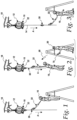
- a release device 10 is provided for use with a fall protection unit 12, shown in the form of an anchorage rescue device (ARD) 12 having a lifeline 14 that can be deployed to protect a worker 16 after a fall event in a fall direction, shown by the arrow "A" in Figs. 1-3 , that typically will be the vertical downward direction defined by the force of gravity.
- ARD anchorage rescue device
- the release device 10 and ARD 12 are shown oversized with respect to the worker 16 in Figs. 1-3 .
- the fall protection unit 12 will be anchored to some sort of rigid structure, such as the I-beam 18 shown in Figs. 1-3 .
- the release device 10 is configured to selectively allow the lifeline 14 to be deployed from the fall protection unit 12 after the worker 16 has experienced a fall event and is left suspended in the air, as shown in Figs. 2 and 3 .
- the release device 10 is configured to allow either a remote release of the lifeline 14 by the worker 16 or by a rescuer, such as another worker 20, or for a rescuer to manually release the lifeline if the rescuer 20 has physical access to the release device 10.
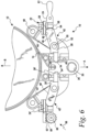
- the release device 10 includes a frame 22, a release member 24, a connection member 26, and a stop link 28.
- the frame 22 is configured to fix the release device 10 to the fall protection unit 12.
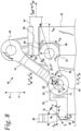
- the release member 24 is mounted for movement (lateral translation in the illustrated embodiment) from a lock position (shown in Figs. 6 and 8 ) to a release position (shown in Fig. 7 ).
- the connection member 26 is configured to connect the lifeline 14 of the fall protection unit 12 to another piece of fall protection equipment, such as the rope grab system 30 and shock absorbing lanyard 32 shown in Figs. 1-3 , to a worker, such as the worker 16 shown in Figs.
- connection member 26 has a locked condition (shown in Figs. 1-6 and 8 ) wherein the connection member 14 is prevented from moving in the fall direction relative to the frame 22 and the fall protection unit 12, and a released condition (shown in Fig. 7 ) wherein the connection member 26 is free to move in the fall direction relative to the frame 22 and the fall protection unit 12.
- a locked condition shown in Figs. 1-6 and 8
- a released condition shown in Fig. 7
- the connection member 26 includes a stop surface 34 that extends at an acute angle ⁇ relative to fall direction, and a connection feature 35 in the form of an opening 35 that can receive a connector (such as a carabineer) of another piece of fall protection equipment, such as the rope grab system 30 or the lanyard 32.
- the stop surface 34 is defined in a recess 36 (best seen in Fig. 7 ) formed in the connection member 26.
- the stop link 28 is mounted to the frame 22 to move from an engaged position (shown in Figs. 6 and 8 ) to a disengaged position (shown in Fig. 7 ) in response to the release member 24 moving from the lock position (shown in Figs.
- the stop link 28 has a hold surface 38 engaged with the stop surface 34 with the stop link 28 in the engaged position and the connection member 26 in the locked condition.
- the hold surface 38 is also a planar surface and extends at the acute angle ⁇ parallel to the stop surface 34 with the stop link 28 in the engaged position and the connection member 26 in the locked condition, and is defined on an end portion 40 of the stop link 28 that is received within the recess 36 of the connection member 26. The stop link 28 is moved away from the connection member 26 and the hold surface 38 is disengaged from the stop surface 34 with the stop link 28 in the disengaged position, as seen in Fig. 7 .
- stop surface 34 and the hold surface 38 are shown as being planar surfaces that extend at the acute angle ⁇ to the fall direction with the connection member 26 in the locked condition and the stop link 28 in the engaged position, in some applications it may be desirable for only one of the surfaces 34 and 38 to be planar and/or to extend at the acute angle ⁇ .
- the release device 10 further includes a linkage 42 connected to the stop link 28 to guide the stop link 28 from the engaged position to the disengaged position in response to the release member 24 moving from the lock position to the release position.
- the linkage 42 includes a guide link 44 and a slide link 46.
- the guide link 44 is pivot mounted to the frame 22 at a first location 48 on the guide link 44, and pivot mounted to the stop link 28 at a second location 50 on the guide link 44 that is spaced from the first location 48 on the guide link 44.
- the slide link 46 has a first portion 52 mounted to at least one of the guide link 44 and the stop link 28, and a second portion 54 spaced from the first portion 52 and mounted for frictional translation relative to the frame 22.
- the slide link 46 is pivot mounted to both the stop link 28 and the guide link 44 at the second location 50, and is mounted to translate in the vertical upward direction (shown by the arrow "B") relative to the frame 22 via a sliding frictional engagement between a cylindrical surface 56 on the second portion 54 and a planar, vertically extending surface 58 on the frame 22.
- the release member 24 is engaged against the slide link 46 with the release member 24 in the lock position and the stop link 28 in the engaged position to prevent translation of the second portion 54 of the slide link 46 relative to the frame 22.
- the cylindrical surface 56 of the second portion 54 of the slide link 46 engages against a planar surface 60 of the release member 24 that extends perpendicular to the fall direction.
- the release member 24 is disengaged from the slide link 46 as the release member 24 is moved from the lock position to the release position to allow the second portion 54 of the slide link 46 to translate relative to the frame 22.
- the guide link 44 extends at an acute angle ⁇ relative to the fall direction
- the slide link extends at an acute angle ⁇ relative to the fall direction with the stop link 28 in the engaged position and the connection member 26 in the locked condition.
- the arrangement of the linkages 28, 44 and 46 allows for the release member 24 to be actuated from the lock position to a release position by a force F pull that is significantly lower (two orders of magnitude lower in the illustrated embodiment) than the force applied to the release device 10 by a worker 16 suspended from the connection member 26.
- the force F pull required to actuate the release member 24 from the lock position to the release position can be derived from the following set of calculations shown in the following example, which uses specific loads and angles to illustrate one advantageous configuration: Max.
- the release device 10 includes an additional release member 24', an additional stop link 28', and an additional linkage 42' including an additional guide link 44' and an additional slide link 46', all located on the opposite side of the connection member 26 from the links 28, 44 and 46, with the stop link 24', guide link 44' and slide link 46' being a mirror image arrangement of the stop link 28, guide link 44 and slide link 46 and operating in the same fashion as previously described from the links 28, 44 and 46.
- the release member 24 in the illustrated embodiment includes a manual grip 61 that is configured to be gripped by a rescuer's/user's hand to manually actuate the release member 24 from the locked position to the released position.
- the release member 24' includes a toothed rack 62 that engages a pinion 64 of a remote controlled electric actuator 66 that is configured to rotate the pinion 64 to drive the toothed rack 62 to the left, thereby actuating the release member 24' from the locked position to the released position in response to a wireless signal 68 from a remotely located user/rescuer 20.
- the remote controlled actuator 66 will include suitable control circuitry and a wireless receiver that are activated by the wireless signal 68 using any suitable wireless protocol, many of which are known, which is transmitted from a wireless transmitter in a suitable remote device 70, many of which are known, carried by a remotely located user/rescuer 20, as best seen in Fig. 2 , or carried by the suspended worker 16.
- remote controlled actuator 66 has been shown in the form of an electric motor driving a pinion 64, it should be appreciated that any suitable linear actuator can be used to translate the release member 24' of the illustrated embodiments from the lock position to the release position.
- any suitable pressure cylinder type linear actuator can be used, including such actuators that are activated via an air charge or via a small explosive charge that pressurize the cylinder in response to the wireless signal 68.
- stop links 28, 28' and linkages 42, 42' and release members 24, 24' on each side of the connection member 26 in many application it will be desirable to have a stop link 24, linkage 42 and release member 24 on only one side of the connection member 26, with the opposite side of the connection member either including a stop surface 34' engaged with a stationary hold surface 38', or simply having a vertical surface that slidingly engages a corresponding vertical surface on the frame 22.
- the single release member 24 may include both the manual grip 61 and a remote controlled actuator 66 of any suitable type to allow both options for moving the single release member 24 from the lock position to the release position.
- the release device 10 of this disclosure allows for the lifeline 14 of a fall protection unit 12 to be released while under load from a worker 16 that has experienced a fall event, with the force required to release the lifeline being significantly ower than the load applied to the lifeline 14 by the suspended worker 16. If should further be appreciated that the release device 10 can be configured to allow for manual release, remote release, or both manual and remote release. It should additionally be appreciated that the release device provides its desired function with very few moving components and with components that are robust and simple to manufacture.
Landscapes
- Health & Medical Sciences (AREA)
- General Health & Medical Sciences (AREA)
- Business, Economics & Management (AREA)
- Emergency Management (AREA)
- Engineering & Computer Science (AREA)
- Mechanical Engineering (AREA)
- Emergency Lowering Means (AREA)
Priority Applications (1)
| Application Number | Priority Date | Filing Date | Title |
|---|---|---|---|
| EP24154014.5A EP4335519B1 (de) | 2016-05-03 | 2016-05-03 | Auslösevorrichtung zur verwendung mit einer sturzsicherungseinheit mit ausfahrbarer rettungsleine |
Applications Claiming Priority (3)
| Application Number | Priority Date | Filing Date | Title |
|---|---|---|---|
| EP16721147.3A EP3452177B1 (de) | 2016-05-03 | 2016-05-03 | Lösevorrichtung zur verwendung mit einer sturzsicherungseinheit mit ausfahrbarer rettungsleine |
| EP24154014.5A EP4335519B1 (de) | 2016-05-03 | 2016-05-03 | Auslösevorrichtung zur verwendung mit einer sturzsicherungseinheit mit ausfahrbarer rettungsleine |
| PCT/EP2016/059926 WO2017190772A1 (en) | 2016-05-03 | 2016-05-03 | Release device for use with a fall protection unit having a deployable lifeline |
Related Parent Applications (2)
| Application Number | Title | Priority Date | Filing Date |
|---|---|---|---|
| EP16721147.3A Division EP3452177B1 (de) | 2016-05-03 | 2016-05-03 | Lösevorrichtung zur verwendung mit einer sturzsicherungseinheit mit ausfahrbarer rettungsleine |
| EP16721147.3A Division-Into EP3452177B1 (de) | 2016-05-03 | 2016-05-03 | Lösevorrichtung zur verwendung mit einer sturzsicherungseinheit mit ausfahrbarer rettungsleine |
Publications (3)
| Publication Number | Publication Date |
|---|---|
| EP4335519A2 true EP4335519A2 (de) | 2024-03-13 |
| EP4335519A3 EP4335519A3 (de) | 2024-03-27 |
| EP4335519B1 EP4335519B1 (de) | 2024-11-13 |
Family
ID=55948823
Family Applications (2)
| Application Number | Title | Priority Date | Filing Date |
|---|---|---|---|
| EP16721147.3A Active EP3452177B1 (de) | 2016-05-03 | 2016-05-03 | Lösevorrichtung zur verwendung mit einer sturzsicherungseinheit mit ausfahrbarer rettungsleine |
| EP24154014.5A Active EP4335519B1 (de) | 2016-05-03 | 2016-05-03 | Auslösevorrichtung zur verwendung mit einer sturzsicherungseinheit mit ausfahrbarer rettungsleine |
Family Applications Before (1)
| Application Number | Title | Priority Date | Filing Date |
|---|---|---|---|
| EP16721147.3A Active EP3452177B1 (de) | 2016-05-03 | 2016-05-03 | Lösevorrichtung zur verwendung mit einer sturzsicherungseinheit mit ausfahrbarer rettungsleine |
Country Status (3)
| Country | Link |
|---|---|
| US (1) | US10994161B2 (de) |
| EP (2) | EP3452177B1 (de) |
| WO (1) | WO2017190772A1 (de) |
Families Citing this family (3)
| Publication number | Priority date | Publication date | Assignee | Title |
|---|---|---|---|---|
| US10022570B2 (en) * | 2016-05-20 | 2018-07-17 | Bailout, LLC | Personal escape device with eddy current braking |
| US10890029B2 (en) * | 2017-09-15 | 2021-01-12 | Simone Simon | Fall arrest ladder system |
| US11633634B2 (en) * | 2018-04-06 | 2023-04-25 | Msa Technology, Llc | Cut-resistant leading edge fall arrest system and method |
Citations (1)
| Publication number | Priority date | Publication date | Assignee | Title |
|---|---|---|---|---|
| US20090173578A1 (en) | 2004-05-15 | 2009-07-09 | Fallsafe Limited | Personal height rescue apparatus |
Family Cites Families (8)
| Publication number | Priority date | Publication date | Assignee | Title |
|---|---|---|---|---|
| US2205026A (en) * | 1939-05-08 | 1940-06-18 | Theophilus A Barham | Fire escape |
| US2479459A (en) * | 1946-05-13 | 1949-08-16 | Safety Scape Corp | Safety supporting and suspension means |
| US4941548A (en) * | 1989-11-17 | 1990-07-17 | Blanchard Mark W | Fall arresting device for climbers |
| GB0428335D0 (en) * | 2004-12-24 | 2005-02-02 | Equip Securite Par Pare Chute | Emergency vertical egress device |
| US10688323B2 (en) * | 2009-03-09 | 2020-06-23 | D B Industries, Llc | Safety device with fall arrest and descending modes |
| GB201112901D0 (en) * | 2011-07-27 | 2011-09-14 | Renton Julian E | Height rescue apparatus |
| GB201303153D0 (en) * | 2013-02-22 | 2013-04-10 | Capital Safety Group Northern Europ Ltd | Fall Arrest Device |
| US20190209877A1 (en) * | 2018-01-08 | 2019-07-11 | Pure Safety Group, Inc. | Retractable lifeline assembly |
-
2016
- 2016-05-03 EP EP16721147.3A patent/EP3452177B1/de active Active
- 2016-05-03 EP EP24154014.5A patent/EP4335519B1/de active Active
- 2016-05-03 WO PCT/EP2016/059926 patent/WO2017190772A1/en not_active Ceased
- 2016-05-03 US US16/098,557 patent/US10994161B2/en active Active
Patent Citations (1)
| Publication number | Priority date | Publication date | Assignee | Title |
|---|---|---|---|---|
| US20090173578A1 (en) | 2004-05-15 | 2009-07-09 | Fallsafe Limited | Personal height rescue apparatus |
Also Published As
| Publication number | Publication date |
|---|---|
| EP4335519A3 (de) | 2024-03-27 |
| EP3452177A1 (de) | 2019-03-13 |
| US20190143158A1 (en) | 2019-05-16 |
| EP4335519B1 (de) | 2024-11-13 |
| EP3452177B1 (de) | 2024-04-17 |
| WO2017190772A1 (en) | 2017-11-09 |
| EP3452177C0 (de) | 2024-04-17 |
| US10994161B2 (en) | 2021-05-04 |
Similar Documents
| Publication | Publication Date | Title |
|---|---|---|
| US9827451B2 (en) | Height rescue apparatus | |
| US10449396B2 (en) | Personal height rescue apparatus | |
| US20110042984A1 (en) | Apparatus for securing rescue operations by helihoisting | |
| US8469400B2 (en) | Seat harness pretensioner | |
| EP3452177B1 (de) | Lösevorrichtung zur verwendung mit einer sturzsicherungseinheit mit ausfahrbarer rettungsleine | |
| AU2011303473B2 (en) | A fall protection system | |
| EP2796172B1 (de) | Absturzsicherungsvorrichtung | |
| EP1468869A2 (de) | Einrichtung zur Positionierung eines Besatzungsmitglieds eines Fahrzeugs | |
| EP3337573B1 (de) | Schiffchen für ein kletterschutzsystem | |
| AT519353B1 (de) | Sicherheitskarabiner und klettersteigset mit sicherheitskarabinern | |
| US20060070809A1 (en) | Advanced "Omer" rescue system | |
| US20110186382A1 (en) | Fall arrest device | |
| CN110650913A (zh) | 矿井运输工具安全制动器 | |
| WO2015044141A1 (en) | A safety clamp | |
| EP3003504B1 (de) | Verbesserungen an einer seilzugangsvorrichtung | |
| US20070067970A1 (en) | Snap hook | |
| WO2013053685A2 (en) | Fall arrest device | |
| WO2006064186A1 (en) | Lifting, lowering or tensioning device for flexible rope, cable or the like | |
| DE102010009084A1 (de) | Personen- oder Lastensteighilfe | |
| EP2407210A1 (de) | Selbstbergender Wagen mit Fallschutz und System damit | |
| GB2451499A (en) | Safety harness arrangement | |
| HK1193780A (en) | Height rescue apparatus | |
| JPS60223776A (ja) | エレベ−タ−乗りかご天井救出口の鎖錠装置 | |
| NZ619680B2 (en) | Height rescue apparatus | |
| DE2259634B1 (de) | Vorrichtung zum abseilen an einem festseil mit seilgleit-bremsvorrichtung |
Legal Events
| Date | Code | Title | Description |
|---|---|---|---|
| PUAI | Public reference made under article 153(3) epc to a published international application that has entered the european phase |
Free format text: ORIGINAL CODE: 0009012 |
|
| STAA | Information on the status of an ep patent application or granted ep patent |
Free format text: STATUS: THE APPLICATION HAS BEEN PUBLISHED |
|
| REG | Reference to a national code |
Ref country code: DE Ref legal event code: R079 Free format text: PREVIOUS MAIN CLASS: A62B0035000000 Ipc: A62B0001100000 Ref country code: DE Ref legal event code: R079 Ref document number: 602016090289 Country of ref document: DE Free format text: PREVIOUS MAIN CLASS: A62B0035000000 Ipc: A62B0001100000 |
|
| PUAL | Search report despatched |
Free format text: ORIGINAL CODE: 0009013 |
|
| AC | Divisional application: reference to earlier application |
Ref document number: 3452177 Country of ref document: EP Kind code of ref document: P |
|
| AK | Designated contracting states |
Kind code of ref document: A2 Designated state(s): AL AT BE BG CH CY CZ DE DK EE ES FI FR GB GR HR HU IE IS IT LI LT LU LV MC MK MT NL NO PL PT RO RS SE SI SK SM TR |
|
| AK | Designated contracting states |
Kind code of ref document: A3 Designated state(s): AL AT BE BG CH CY CZ DE DK EE ES FI FR GB GR HR HU IE IS IT LI LT LU LV MC MK MT NL NO PL PT RO RS SE SI SK SM TR |
|
| RIC1 | Information provided on ipc code assigned before grant |
Ipc: A62B 35/00 20060101ALI20240221BHEP Ipc: A62B 1/10 20060101AFI20240221BHEP |
|
| STAA | Information on the status of an ep patent application or granted ep patent |
Free format text: STATUS: REQUEST FOR EXAMINATION WAS MADE |
|
| 17P | Request for examination filed |
Effective date: 20240501 |
|
| RBV | Designated contracting states (corrected) |
Designated state(s): AL AT BE BG CH CY CZ DE DK EE ES FI FR GB GR HR HU IE IS IT LI LT LU LV MC MK MT NL NO PL PT RO RS SE SI SK SM TR |
|
| GRAP | Despatch of communication of intention to grant a patent |
Free format text: ORIGINAL CODE: EPIDOSNIGR1 |
|
| STAA | Information on the status of an ep patent application or granted ep patent |
Free format text: STATUS: GRANT OF PATENT IS INTENDED |
|
| RIC1 | Information provided on ipc code assigned before grant |
Ipc: A62B 35/00 20060101ALI20240530BHEP Ipc: A62B 1/10 20060101AFI20240530BHEP |
|
| INTG | Intention to grant announced |
Effective date: 20240612 |
|
| GRAS | Grant fee paid |
Free format text: ORIGINAL CODE: EPIDOSNIGR3 |
|
| GRAA | (expected) grant |
Free format text: ORIGINAL CODE: 0009210 |
|
| STAA | Information on the status of an ep patent application or granted ep patent |
Free format text: STATUS: THE PATENT HAS BEEN GRANTED |
|
| AC | Divisional application: reference to earlier application |
Ref document number: 3452177 Country of ref document: EP Kind code of ref document: P |
|
| AK | Designated contracting states |
Kind code of ref document: B1 Designated state(s): AL AT BE BG CH CY CZ DE DK EE ES FI FR GB GR HR HU IE IS IT LI LT LU LV MC MK MT NL NO PL PT RO RS SE SI SK SM TR |
|
| REG | Reference to a national code |
Ref country code: GB Ref legal event code: FG4D |
|
| REG | Reference to a national code |
Ref country code: CH Ref legal event code: EP |
|
| REG | Reference to a national code |
Ref country code: IE Ref legal event code: FG4D |
|
| REG | Reference to a national code |
Ref country code: DE Ref legal event code: R096 Ref document number: 602016090289 Country of ref document: DE |
|
| REG | Reference to a national code |
Ref country code: LT Ref legal event code: MG9D |
|
| REG | Reference to a national code |
Ref country code: NL Ref legal event code: MP Effective date: 20241113 |
|
| PG25 | Lapsed in a contracting state [announced via postgrant information from national office to epo] |
Ref country code: HR Free format text: LAPSE BECAUSE OF FAILURE TO SUBMIT A TRANSLATION OF THE DESCRIPTION OR TO PAY THE FEE WITHIN THE PRESCRIBED TIME-LIMIT Effective date: 20241113 Ref country code: IS Free format text: LAPSE BECAUSE OF FAILURE TO SUBMIT A TRANSLATION OF THE DESCRIPTION OR TO PAY THE FEE WITHIN THE PRESCRIBED TIME-LIMIT Effective date: 20250313 Ref country code: PT Free format text: LAPSE BECAUSE OF FAILURE TO SUBMIT A TRANSLATION OF THE DESCRIPTION OR TO PAY THE FEE WITHIN THE PRESCRIBED TIME-LIMIT Effective date: 20250313 |
|
| PG25 | Lapsed in a contracting state [announced via postgrant information from national office to epo] |
Ref country code: FI Free format text: LAPSE BECAUSE OF FAILURE TO SUBMIT A TRANSLATION OF THE DESCRIPTION OR TO PAY THE FEE WITHIN THE PRESCRIBED TIME-LIMIT Effective date: 20241113 Ref country code: NL Free format text: LAPSE BECAUSE OF FAILURE TO SUBMIT A TRANSLATION OF THE DESCRIPTION OR TO PAY THE FEE WITHIN THE PRESCRIBED TIME-LIMIT Effective date: 20241113 |
|
| REG | Reference to a national code |
Ref country code: AT Ref legal event code: MK05 Ref document number: 1741228 Country of ref document: AT Kind code of ref document: T Effective date: 20241113 |
|
| PG25 | Lapsed in a contracting state [announced via postgrant information from national office to epo] |
Ref country code: BG Free format text: LAPSE BECAUSE OF FAILURE TO SUBMIT A TRANSLATION OF THE DESCRIPTION OR TO PAY THE FEE WITHIN THE PRESCRIBED TIME-LIMIT Effective date: 20241113 |
|
| PG25 | Lapsed in a contracting state [announced via postgrant information from national office to epo] |
Ref country code: ES Free format text: LAPSE BECAUSE OF FAILURE TO SUBMIT A TRANSLATION OF THE DESCRIPTION OR TO PAY THE FEE WITHIN THE PRESCRIBED TIME-LIMIT Effective date: 20241113 |
|
| PG25 | Lapsed in a contracting state [announced via postgrant information from national office to epo] |
Ref country code: NO Free format text: LAPSE BECAUSE OF FAILURE TO SUBMIT A TRANSLATION OF THE DESCRIPTION OR TO PAY THE FEE WITHIN THE PRESCRIBED TIME-LIMIT Effective date: 20250213 |
|
| PG25 | Lapsed in a contracting state [announced via postgrant information from national office to epo] |
Ref country code: AT Free format text: LAPSE BECAUSE OF FAILURE TO SUBMIT A TRANSLATION OF THE DESCRIPTION OR TO PAY THE FEE WITHIN THE PRESCRIBED TIME-LIMIT Effective date: 20241113 Ref country code: GR Free format text: LAPSE BECAUSE OF FAILURE TO SUBMIT A TRANSLATION OF THE DESCRIPTION OR TO PAY THE FEE WITHIN THE PRESCRIBED TIME-LIMIT Effective date: 20250214 Ref country code: LV Free format text: LAPSE BECAUSE OF FAILURE TO SUBMIT A TRANSLATION OF THE DESCRIPTION OR TO PAY THE FEE WITHIN THE PRESCRIBED TIME-LIMIT Effective date: 20241113 |
|
| PG25 | Lapsed in a contracting state [announced via postgrant information from national office to epo] |
Ref country code: PL Free format text: LAPSE BECAUSE OF FAILURE TO SUBMIT A TRANSLATION OF THE DESCRIPTION OR TO PAY THE FEE WITHIN THE PRESCRIBED TIME-LIMIT Effective date: 20241113 |
|
| PG25 | Lapsed in a contracting state [announced via postgrant information from national office to epo] |
Ref country code: RS Free format text: LAPSE BECAUSE OF FAILURE TO SUBMIT A TRANSLATION OF THE DESCRIPTION OR TO PAY THE FEE WITHIN THE PRESCRIBED TIME-LIMIT Effective date: 20250213 |
|
| REG | Reference to a national code |
Ref country code: DE Ref legal event code: R081 Ref document number: 602016090289 Country of ref document: DE Owner name: HONEYWELL SAFETY PRODUCTS USA, INC., WILMINGTO, US Free format text: FORMER OWNER: HONEYWELL INTERNATIONAL INC., MORRIS PLAINS, NJ, US |
|
| REG | Reference to a national code |
Ref country code: GB Ref legal event code: 732E Free format text: REGISTERED BETWEEN 20250515 AND 20250521 |
|
| PG25 | Lapsed in a contracting state [announced via postgrant information from national office to epo] |
Ref country code: SM Free format text: LAPSE BECAUSE OF FAILURE TO SUBMIT A TRANSLATION OF THE DESCRIPTION OR TO PAY THE FEE WITHIN THE PRESCRIBED TIME-LIMIT Effective date: 20241113 |
|
| PGFP | Annual fee paid to national office [announced via postgrant information from national office to epo] |
Ref country code: DE Payment date: 20250528 Year of fee payment: 10 |
|
| PG25 | Lapsed in a contracting state [announced via postgrant information from national office to epo] |
Ref country code: DK Free format text: LAPSE BECAUSE OF FAILURE TO SUBMIT A TRANSLATION OF THE DESCRIPTION OR TO PAY THE FEE WITHIN THE PRESCRIBED TIME-LIMIT Effective date: 20241113 |
|
| PGFP | Annual fee paid to national office [announced via postgrant information from national office to epo] |
Ref country code: GB Payment date: 20250520 Year of fee payment: 10 |
|
| PG25 | Lapsed in a contracting state [announced via postgrant information from national office to epo] |
Ref country code: EE Free format text: LAPSE BECAUSE OF FAILURE TO SUBMIT A TRANSLATION OF THE DESCRIPTION OR TO PAY THE FEE WITHIN THE PRESCRIBED TIME-LIMIT Effective date: 20241113 |
|
| PGFP | Annual fee paid to national office [announced via postgrant information from national office to epo] |
Ref country code: FR Payment date: 20250526 Year of fee payment: 10 |
|
| PG25 | Lapsed in a contracting state [announced via postgrant information from national office to epo] |
Ref country code: RO Free format text: LAPSE BECAUSE OF FAILURE TO SUBMIT A TRANSLATION OF THE DESCRIPTION OR TO PAY THE FEE WITHIN THE PRESCRIBED TIME-LIMIT Effective date: 20241113 |
|
| PG25 | Lapsed in a contracting state [announced via postgrant information from national office to epo] |
Ref country code: SK Free format text: LAPSE BECAUSE OF FAILURE TO SUBMIT A TRANSLATION OF THE DESCRIPTION OR TO PAY THE FEE WITHIN THE PRESCRIBED TIME-LIMIT Effective date: 20241113 |
|
| PG25 | Lapsed in a contracting state [announced via postgrant information from national office to epo] |
Ref country code: CZ Free format text: LAPSE BECAUSE OF FAILURE TO SUBMIT A TRANSLATION OF THE DESCRIPTION OR TO PAY THE FEE WITHIN THE PRESCRIBED TIME-LIMIT Effective date: 20241113 |
|
| PG25 | Lapsed in a contracting state [announced via postgrant information from national office to epo] |
Ref country code: IT Free format text: LAPSE BECAUSE OF FAILURE TO SUBMIT A TRANSLATION OF THE DESCRIPTION OR TO PAY THE FEE WITHIN THE PRESCRIBED TIME-LIMIT Effective date: 20241113 |
|
| REG | Reference to a national code |
Ref country code: DE Ref legal event code: R097 Ref document number: 602016090289 Country of ref document: DE |
|
| PG25 | Lapsed in a contracting state [announced via postgrant information from national office to epo] |
Ref country code: SE Free format text: LAPSE BECAUSE OF FAILURE TO SUBMIT A TRANSLATION OF THE DESCRIPTION OR TO PAY THE FEE WITHIN THE PRESCRIBED TIME-LIMIT Effective date: 20241113 |
|
| PLBE | No opposition filed within time limit |
Free format text: ORIGINAL CODE: 0009261 |
|
| STAA | Information on the status of an ep patent application or granted ep patent |
Free format text: STATUS: NO OPPOSITION FILED WITHIN TIME LIMIT |
|
| 26N | No opposition filed |
Effective date: 20250814 |
|
| REG | Reference to a national code |
Ref country code: CH Ref legal event code: H13 Free format text: ST27 STATUS EVENT CODE: U-0-0-H10-H13 (AS PROVIDED BY THE NATIONAL OFFICE) Effective date: 20251223 |
|
| PG25 | Lapsed in a contracting state [announced via postgrant information from national office to epo] |
Ref country code: LU Free format text: LAPSE BECAUSE OF NON-PAYMENT OF DUE FEES Effective date: 20250503 |
|
| PG25 | Lapsed in a contracting state [announced via postgrant information from national office to epo] |
Ref country code: CH Free format text: LAPSE BECAUSE OF NON-PAYMENT OF DUE FEES Effective date: 20250531 |
|
| REG | Reference to a national code |
Ref country code: BE Ref legal event code: MM Effective date: 20250531 |
|
| PG25 | Lapsed in a contracting state [announced via postgrant information from national office to epo] |
Ref country code: MC Free format text: LAPSE BECAUSE OF FAILURE TO SUBMIT A TRANSLATION OF THE DESCRIPTION OR TO PAY THE FEE WITHIN THE PRESCRIBED TIME-LIMIT Effective date: 20241113 |
|
| PG25 | Lapsed in a contracting state [announced via postgrant information from national office to epo] |
Ref country code: IE Free format text: LAPSE BECAUSE OF NON-PAYMENT OF DUE FEES Effective date: 20250503 |
|
| PG25 | Lapsed in a contracting state [announced via postgrant information from national office to epo] |
Ref country code: BE Free format text: LAPSE BECAUSE OF NON-PAYMENT OF DUE FEES Effective date: 20250531 |