EP4335339A1 - Hand-held vacuum cleaner - Google Patents
Hand-held vacuum cleaner Download PDFInfo
- Publication number
- EP4335339A1 EP4335339A1 EP22803604.2A EP22803604A EP4335339A1 EP 4335339 A1 EP4335339 A1 EP 4335339A1 EP 22803604 A EP22803604 A EP 22803604A EP 4335339 A1 EP4335339 A1 EP 4335339A1
- Authority
- EP
- European Patent Office
- Prior art keywords
- engagement portion
- dust
- vacuum cleaner
- dust cup
- assembly
- Prior art date
- Legal status (The legal status is an assumption and is not a legal conclusion. Google has not performed a legal analysis and makes no representation as to the accuracy of the status listed.)
- Pending
Links
- 239000000428 dust Substances 0.000 claims abstract description 276
- 238000004891 communication Methods 0.000 claims abstract description 9
- 238000007599 discharging Methods 0.000 claims description 31
- 229920000742 Cotton Polymers 0.000 claims description 23
- 238000004140 cleaning Methods 0.000 description 12
- 238000001914 filtration Methods 0.000 description 9
- 239000012535 impurity Substances 0.000 description 4
- 239000000463 material Substances 0.000 description 4
- 238000003825 pressing Methods 0.000 description 3
- 241001657948 Midea Species 0.000 description 2
- 238000009825 accumulation Methods 0.000 description 2
- 238000000926 separation method Methods 0.000 description 2
- 230000003749 cleanliness Effects 0.000 description 1
- 230000006835 compression Effects 0.000 description 1
- 238000007906 compression Methods 0.000 description 1
- 238000005516 engineering process Methods 0.000 description 1
- 238000000034 method Methods 0.000 description 1
- 238000012986 modification Methods 0.000 description 1
- 230000004048 modification Effects 0.000 description 1
Images


Classifications
-
- A—HUMAN NECESSITIES
- A47—FURNITURE; DOMESTIC ARTICLES OR APPLIANCES; COFFEE MILLS; SPICE MILLS; SUCTION CLEANERS IN GENERAL
- A47L—DOMESTIC WASHING OR CLEANING; SUCTION CLEANERS IN GENERAL
- A47L5/00—Structural features of suction cleaners
- A47L5/12—Structural features of suction cleaners with power-driven air-pumps or air-compressors, e.g. driven by motor vehicle engine vacuum
- A47L5/22—Structural features of suction cleaners with power-driven air-pumps or air-compressors, e.g. driven by motor vehicle engine vacuum with rotary fans
- A47L5/24—Hand-supported suction cleaners
-
- A—HUMAN NECESSITIES
- A47—FURNITURE; DOMESTIC ARTICLES OR APPLIANCES; COFFEE MILLS; SPICE MILLS; SUCTION CLEANERS IN GENERAL
- A47L—DOMESTIC WASHING OR CLEANING; SUCTION CLEANERS IN GENERAL
- A47L9/00—Details or accessories of suction cleaners, e.g. mechanical means for controlling the suction or for effecting pulsating action; Storing devices specially adapted to suction cleaners or parts thereof; Carrying-vehicles specially adapted for suction cleaners
- A47L9/10—Filters; Dust separators; Dust removal; Automatic exchange of filters
- A47L9/106—Dust removal
-
- A—HUMAN NECESSITIES
- A47—FURNITURE; DOMESTIC ARTICLES OR APPLIANCES; COFFEE MILLS; SPICE MILLS; SUCTION CLEANERS IN GENERAL
- A47L—DOMESTIC WASHING OR CLEANING; SUCTION CLEANERS IN GENERAL
- A47L9/00—Details or accessories of suction cleaners, e.g. mechanical means for controlling the suction or for effecting pulsating action; Storing devices specially adapted to suction cleaners or parts thereof; Carrying-vehicles specially adapted for suction cleaners
- A47L9/10—Filters; Dust separators; Dust removal; Automatic exchange of filters
- A47L9/16—Arrangement or disposition of cyclones or other devices with centrifugal action
- A47L9/1608—Cyclonic chamber constructions
-
- A—HUMAN NECESSITIES
- A47—FURNITURE; DOMESTIC ARTICLES OR APPLIANCES; COFFEE MILLS; SPICE MILLS; SUCTION CLEANERS IN GENERAL
- A47L—DOMESTIC WASHING OR CLEANING; SUCTION CLEANERS IN GENERAL
- A47L9/00—Details or accessories of suction cleaners, e.g. mechanical means for controlling the suction or for effecting pulsating action; Storing devices specially adapted to suction cleaners or parts thereof; Carrying-vehicles specially adapted for suction cleaners
- A47L9/10—Filters; Dust separators; Dust removal; Automatic exchange of filters
- A47L9/16—Arrangement or disposition of cyclones or other devices with centrifugal action
- A47L9/1658—Construction of outlets
- A47L9/1666—Construction of outlets with filtering means
-
- A—HUMAN NECESSITIES
- A47—FURNITURE; DOMESTIC ARTICLES OR APPLIANCES; COFFEE MILLS; SPICE MILLS; SUCTION CLEANERS IN GENERAL
- A47L—DOMESTIC WASHING OR CLEANING; SUCTION CLEANERS IN GENERAL
- A47L9/00—Details or accessories of suction cleaners, e.g. mechanical means for controlling the suction or for effecting pulsating action; Storing devices specially adapted to suction cleaners or parts thereof; Carrying-vehicles specially adapted for suction cleaners
- A47L9/10—Filters; Dust separators; Dust removal; Automatic exchange of filters
- A47L9/16—Arrangement or disposition of cyclones or other devices with centrifugal action
- A47L9/1683—Dust collecting chambers; Dust collecting receptacles
-
- A—HUMAN NECESSITIES
- A47—FURNITURE; DOMESTIC ARTICLES OR APPLIANCES; COFFEE MILLS; SPICE MILLS; SUCTION CLEANERS IN GENERAL
- A47L—DOMESTIC WASHING OR CLEANING; SUCTION CLEANERS IN GENERAL
- A47L9/00—Details or accessories of suction cleaners, e.g. mechanical means for controlling the suction or for effecting pulsating action; Storing devices specially adapted to suction cleaners or parts thereof; Carrying-vehicles specially adapted for suction cleaners
- A47L9/10—Filters; Dust separators; Dust removal; Automatic exchange of filters
- A47L9/16—Arrangement or disposition of cyclones or other devices with centrifugal action
- A47L9/1691—Mounting or coupling means for cyclonic chamber or dust receptacles
Definitions
- the present disclosure relates to the field of cleaning technologies, and more particularly, to a hand-held vacuum cleaner.
- a dust cup, a filter assembly, and the like of a conventional hand-held vacuum cleaner are separated from each other.
- the dust cup and the filter assembly need to be sequentially detached from a machine body of the hand-held vacuum cleaner, which results in a cumbersome disassembly and cleaning process of the hand-held vacuum cleaner and gives rise to complaints of a user.
- removing the dust cup and the filter assembly sequentially is likely to cause dust to be escaped from the dust cup and/or the filter assembly. The escaped dust would fall on user's hands, which further compromises use experience of the user.
- the present disclosure aims to solve at least one of the technical problems in the related art.
- the present disclosure provides a hand-held vacuum cleaner, which offers a simple disassembly and cleaning, and also prevents dust from escaping from a dust cup and a filter assembly.
- a hand-held vacuum cleaner comprises a machine body and a dust cup assembly.
- the machine body comprises a housing and a fan.
- the fan is provided in the housing.
- the housing has a connection assembly provided at the housing.
- the connection assembly has a suction air duct provided in the connection assembly.
- the machine body has a first engagement portion provided at the machine body.
- the dust cup assembly comprises a dust cup, a filter assembly, a second engagement portion, and an actuator.
- the dust cup has an air inlet.
- the filter assembly is removably provided in the dust cup.
- Each of the second engagement portion and the actuator is provided at the dust cup.
- the actuator is engaged with the second engagement portion to control the second engagement portion to move to a disengagement position when the actuator is actuated.
- the second engagement portion is disengaged from the first engagement portion to allow the dust cup assembly to be removed, and when the second engagement portion is engaged with the first engagement portion, the dust cup assembly is mounted to the machine body and the suction air duct is in communication with the air inlet.
- the filter assembly is removably disposed in the dust cup, and the dust cup assembly is removably mounted at the machine body.
- the dust cup assembly can simplify a disassembly and cleaning of the hand-held vacuum cleaner, and also prevent dust from escaping from the dust cup and/or the filter assembly.
- the first engagement portion is a snapping groove formed at the housing.
- the second engagement portion is a snapping hook. When the actuator is pressed, the snapping hook moves away from the snapping groove to be disengaged from the snapping groove.
- the second engagement portion is an elastic snapping hook.
- the second engagement portion is compressed and deformed to be assembled in the snapping groove during an assembly, and restore the deformation after being assembled in place and collide with the snapping groove to make an alert.
- the suction air duct has an end provided with a seal of a ring shape.
- the dust cup assembly is in contact with the seal when the dust cup assembly is mounted to the machine body.
- connection assembly and the actuator are located on a same side of the handheld vacuum cleaner.
- the dust cup comprises a cup body and an end cover.
- the filter assembly is disposed in the cup body.
- Each of the second engagement portion and the actuator are disposed at the cup body.
- the cup body has a dust outlet formed at a bottom of the cup body.
- the end cover is movably provided at the dust outlet to expose or cover the dust outlet.
- the end cover has an end rotatably connected to the cup body and another end provided with a third engagement portion.
- a fourth engagement portion is provided at the cup body and disengaged from or engaged with the third engagement portion.
- the dust discharging member is connected to the fourth engagement portion. The dust discharging member controls, when being actuated, the fourth engagement portion to be disengaged from the third engagement portion to expose the end cove r.
- the third engagement portion is hooked and engaged with the fourth engagement portion.
- the fourth engagement portion moves away from the third engagement portion to be disengaged from the third engagement portion.
- the dust discharging member and the actuator are located at a same side of the dust cup.
- the machine body has a first positioning portion provided at the machine body
- the dust cup has a second positioning portion provided at the dust cup.
- the first positioning portion is engaged with the second positioning portion to position the dust cup assembly.
- the filter assembly comprises a cyclone separator removably provided in the dust cup.
- the air inlet is located at a circumferential side of the cyclone separator.
- the filter assembly further comprises filter cotton removably provided at an air outlet end of the cyclone separator.
- a hand-held vacuum cleaner 100 according to the embodiments of the present disclosure will be described below with reference to FIG. 1 to FIG. 7 .
- the hand-held vacuum cleaner 100 comprises a machine body 1 and a dust cup assembly 2.
- the machine body 1 comprises a fan 12 and a housing 11.
- the fan 12 is disposed in the housing 11.
- the fan 12 may be a centrifugal fan.
- the housing 11 is provided with a connection assembly 13.
- the connection assembly 13 is provided with a suction air duct 14.
- the suction air duct 14 has a housing air inlet 18 located at the housing 11.
- the housing 11 may have a housing air outlet 19 formed at the housing 11.
- the housing air inlet 18 may be formed at a front end of the housing 11 in FIG. 2
- the housing air outlet 19 may be formed at an upper end of the housing 11 in FIG. 2 .
- air inside the housing 11 may be compressed by the fan 12.
- the fan 12 may discharge the compressed air inside the housing 11 out of the housing 11 through the housing air outlet 19.
- a negative pressure may be formed inside the machine body 1. Under the negative pressure inside the machine body 1, air may be supplied to the fan 12 after passing through, via the housing air inlet 18, the suction air duct 14 and the dust cup assembly 2 sequentially, to balance an air pressure of the fan 12.
- the machine body 1 is provided with a first engagement portion 151.
- the dust cup assembly 2 comprises a dust cup 21, a filter assembly 4, a second engagement portion 22, and an actuator 23.
- the dust cup 21 has an air inlet 24.
- the filter assembly 4 is removably provided in the dust cup 21.
- Each of the second engagement portion 22 and the actuator 23 is provided at the dust cup 21.
- the actuator 23 is engaged with the second engagement portion 22. When being actuated, the actuator 23 can control the second engagement portion 22 to move to a disengagement position. At the disengagement position, the second engagement portion 22 is disengaged from the first engagement portion 15 to allow the dust cup assembly 2 to be removed.
- the dust cup assembly 2 is mounted to the machine body 1 and the suction air duct 14 is in communication with the air inlet 24.
- the hand-held vacuum cleaner further comprises a vacuum cleaner head (not illustrated).
- the vacuum cleaner head may move on a to-be-cleaned object, such as a floor, a sofa, or the like, to suck air with impurities such as dust.
- the vacuum cleaner head may be connected to the connection assembly 13 by a tube, or may be mounted directly at the connection assembly 13.
- the air with impurities is sucked through the vacuum cleaner head.
- the air sucked through the hand-held vacuum cleaner 100 is described below as dusty air. However, it should be understood that the air sucked through the hand-held vacuum cleaner 100 carries not only dust but also impurities such as hair.
- the dusty air when the hand-held vacuum cleaner 100 is turned on, the dusty air is sucked through the vacuum cleaner head. When flowing into the machine body 1, the dusty air needs to pass through the dust cup assembly 2. When the dusty air passes through the dust cup assembly 2, the dust in the dusty air may stay in the filter assembly after being filtered by the filter assembly. After the dusty air is filtered by the filter assembly 4, the dust may stay in the dust cup 21, while clean air may flow out of the dust cup assembly 2 through an air outlet 29 of the dust cup assembly 2 opposite to the housing air outlet 19. The clean air may be compressed by the fan 12 and then flow out of the machine body 1 through the housing air outlet 19. Therefore, dust vacuuming can be implemented by the hand-held vacuum cleaner 100.
- the dust cup assembly 2 is removably mounted at the machine body 1.
- the machine body 1 has a mounting position at which the dust cup assembly 2 may be mounted.
- the dust cup assembly 2 may be removed from the machine body 1 when the dust cup assembly 2 needs to be cleaned or dusted.
- the machine body 1 is provided with the first engagement portion 15, and the dust cup 21 is provided with the second engagement portion 22.
- the second engagement portion 22 may be selectively engaged with the first engagement portion 15.
- the actuator 23 is connected to the second engagement portion 22. Further, the actuator 23 can control the second engagement portion 22 to move between the disengagement position and a locking position.
- the actuator 23 can drive the second engagement portion 22 to move from the locking position to the disengagement position to unlock the dust cup assembly 2 from the machine body 1.
- the dust cup assembly 2 may be removed from the machine body 1 in an unlocked state. A user can clean or dust the removed dust cup assembly 2.
- the filter assembly 4 is removably disposed in the dust cup 21, the dust cup 21 and the filter assembly 4 may be disengaged from the machine body 1 simultaneously when the dust cup assembly 2 is removed from the machine body 1.
- a disassembly and cleaning of the hand-held vacuum cleaner 100 can be simplified.
- the user is free from worrying about an escape of the dust from the dust cup 21 and/or the filter assembly 4 when removing the dust cup assembly 2 from the machine body 1, which improves the user's product satisfaction with the hand-held vacuum cleaner 100.
- the dust cup assembly in some hand-held vacuum cleaners in the related art is also removable.
- the dust cup assembly is connected to a connection assembly engaged with the vacuum cleaner head. Therefore, after the removing, the dust cup assembly cannot be cleaned directly due to a presence of the connection assembly.
- the dust cup assembly has a heavy overall weight, which makes it uneasy to be removed.
- the connection assembly 13 connected to the vacuum cleaner head is disposed at the housing 11.
- the dust cup assembly 2 is detached.
- the dust cup assembly 2 is provided with no connection assembly. Instead, the removable filter assembly is disposed in the dust cup to integrate the dust cup assembly. Therefore, the entire dust cup assembly can be removed for cleaning, which facilitates removal of the dust.
- the dust cup assembly has a lighter weight, which facilitates a detachment of the dust cup assembly.
- the filter assembly may also be removed from the dust cup for cleaning or replacement.
- the dust cup assembly 2 may be mounted at the mounting position by assembling the dust cup assembly 2 with the machine body 1.
- the actuator 23 is not actuated when assembling the dust cup assembly 2 with the machine body 1, and thus the second engagement portion 22 is returned to the locking position to be engaged with the first engagement portion 15, to lock the dust cup assembly 2 at the machine body 1.
- the dust cup assembly 2 can be fixed to the machine body 1.
- the dust cup assembly 2 at the mounting position may be in communication with the suction air duct 14.
- the dusty air in the suction air duct 14 may enter the dust cup assembly 2 through the air inlet 24 for filtration.
- the dust cup with the filter assembly may be removed from the machine body 1 for cleaning, which not only simplifies the removing of the dust cup assembly, but also prevents the dust and other impurities from escaping from the dust cup and/or the filter assembly. Also, the entire dust cup assembly can be removed for cleaning, which facilitates the removal of the dust.
- the actuator when being actuated can separate the second engagement portion 22 from the first engagement portion 15 to enable a removal of the dust cup assembly 2, facilitating the removing of the dust cup assembly 2.
- the first engagement portion 15 may be a snapping groove formed at the housing 11.
- the second engagement portion 22 may be a snapping hook.
- the snapping hook When the actuator 23 is pressed, the snapping hook may move away from the snapping groove and may be disengaged from the snapping groove.
- a direction in which the snapping hook moves away from the snapping groove may refer to a forward direction in FIG. 2 .
- the part of the snapping hook extending into the snapping groove may abut with the snapping groove.
- the snapping groove is adapted to restrict a movement of the snapping hook in a height direction of the hand-held vacuum cleaner 100.
- the height direction of the hand-held vacuum cleaner 100 may refer to an up-down direction in FIG. 2 .
- the snapping hook cannot be disengaged from the snapping groove.
- the snapping hook may be connected to the dust cup assembly 2, and the snapping groove can restrict a movement of the dust cup assembly 2 by the snapping hook. Therefore, the dust cup assembly 2 is fixedly connected to the machine body 1.
- the actuator 23 can drive the snapping hook to move away from the snapping groove.
- the snapping hook does not abut with the snapping groove, and thus the snapping groove cannot restrict the movement of the snapping hook in the height direction of the hand-held vacuum cleaner 100.
- the snapping groove cannot restrict the movement of the dust cup assembly 2 by the snapping hook.
- the dust cup assembly 2 can move relative to the machine body 1 in the height direction of the hand-held vacuum cleaner 100. In this case, the dust cup assembly 2 can be removed from the machine body 1.
- fixing and removing of the dust cup assembly can be achieved by means of the engagement between the snapping hook and the snapping groove. Therefore, the engagement relation is simple and reliable.
- the second engagement portion 22 may be constructed as an elastic snapping hook.
- the second engagement portion 22 may be configured to be assembled in the snapping groove through compression and deformation.
- the elastic snapping hook may restore its deformation and collide with the snapping groove.
- the elastic snapping hook may make an alert when colliding with the snapping groove.
- An end of the snapping groove may be provided with a first guide portion 110.
- an end of the elastic snapping hook may be provided with a second guide portion 210.
- the end of the snapping groove provided with the first guide portion 110 may refer to a bottom end of the snapping groove in FIG. 2
- the end of the elastic snapping hook provided with the second guide portion 210 may refer to a top end of the elastic snapping hook.
- the first guide portion 110 and the second guide portion 210 may cooperate with each other in a guiding manner.
- each of the first guide portion 110 and the second guide portion 210 may be constructed as an inclined surface.
- the first guide portion 110 is adapted to abut with the second guide portion 210.
- the second guide portion 210 may move along a surface of the first guide portion 110.
- the first guide portion 110 may drive the elastic snapping hook to be compressed and deformed.
- the elastic snapping hook when being compressed and deformed, may move away from the snapping groove.
- the elastic snapping hook may extend into the snapping groove under an elastic force, and the snapping groove may limit a position of the elastic snapping hook.
- the snapping groove may generate an impact sound when subjected to a collision.
- the impact sound may be set as the alert.
- the alert may remind the user that the dust cup assembly 2 and the machine body 1 are assembled in place.
- the alert can remind the user whether the dust cup assembly 2 and the machine body 1 are assembled in place. In this way, it is possible to prevent the dust cup assembly 2 from falling off from the machine body 1 during use of the hand-held vacuum cleaner 100 due to a failure to mount the dust cup assembly 2 in position, which in turn improves operation stability of the hand-held vacuum cleaner 100.
- a seal 16 may be disposed at the end of the suction air duct 14.
- the seal 16 may be formed into a ring structure.
- the seal 16 may be in contact with the dust cup assembly 2 when the dust cup assembly 2 is mounted to the machine body 1.
- the seal 16 may be a rubber member.
- the seal 16 may be disposed at an end of the suction air duct 14 close to the dust cup assembly 2.
- the end of the suction air duct 14 close to the dust cup assembly 2 may refer to a rear end of the suction air duct 14 in FIG. 2 .
- the seal 16 may extend in an axial direction of the suction air duct 14.
- the axial direction of the suction air duct 14 may refer to a front-rear direction in FIG. 2 .
- the seal 16 is adapted to abut with the dust cup assembly 2.
- the dust cup assembly 2 may compress the seal 16.
- the seal 16 is deformed when compressed.
- the seal 16 may seal a gap between the air inlet 24 and the suction air duct 14.
- the hand-held vacuum cleaner 100 is in an operation state, the dusty air inside the suction air duct 14 cannot flow into the housing 11 through the gap between the air inlet 24 and the suction air duct 14. Therefore, cleanliness and neatness in the housing 11 can be ensured, which further improves a product quality of the hand-held vacuum cleaner 100.
- the actuator 23 and the connection assembly 13 are located on one side of the hand-held vacuum cleaner 100.
- Each of the actuator 23 and the connection assembly 13 may be disposed at a front side of the hand-held vacuum cleaner 100.
- a handle 111 may be further disposed at a rear side of the housing 11. The handle 111 may be held by the user to operate the hand-held vacuum cleaner 100.
- connection assembly 13 By arranging the connection assembly 13 at the front side of the hand-held vacuum cleaner 100, an opening direction of the housing air inlet 18 formed at the connection assembly 13 may be directed towards a front side of the user when the hand-held vacuum cleaner 100 held by the user, which facilitates mounting the vacuum cleaner head by the user.
- actuator 23 by arranging the actuator 23 at the front side of the hand-held vacuum cleaner 100, interference between the actuator 23 and the handle 111 can be avoided, and an actuating region of the actuator 23 can be enlarged. In this way, the dust cup assembly 2 can be easily unlocked by the user through the actuator 23, which in turn can improve the user's satisfaction with the hand-held vacuum cleaner 100.
- the dust cup 21 may comprise a cup body 25 and an end cover 3.
- the filter assembly 4 may be provided in the cup body 25.
- Each of the actuator 23 and the second engagement portion 22 may be provided at the cup body 25.
- a dust outlet 26 may be formed at a bottom of the cup body 25.
- the end cover 3 is movably provided at the dust outlet 26.
- the end cover 3 can expose or cover the dust outlet.
- a deformable elastic piece 6 is provided between the actuator 23 and the cup body 25.
- the actuator 23, the elastic piece 6, and the second engagement portion 22 may be integrally formed.
- the elastic piece 6 When the user presses the actuator 23, the elastic piece 6 may be compressed and elastically deformed, and the actuator 23 can drive the second engagement portion 22 to move away from the snapping groove. That is, the second engagement portion 22 can move from the locking position to the disengagement position.
- the dust cup assembly 2 may be removed from the machine body 1 when being unlocked.
- the elastic piece 6 When the user stops compressing the actuator, the elastic piece 6 is restored under the elastic force. During the restoring of the elastic piece 6, the elastic piece 6 can drive the second engagement portion 22 to move towards the snapping groove to be restored. The user may then mount the dust cup assembly 2 onto the machine body 1, during which the second engagement portion 22 is compressed and deformed to be assembled in the snapping groove.
- the elastic snapping hook When the elastic snapping hook is assembled with the snapping groove in place, the elastic snapping hook may restore its deformation and collide with the snapping groove. The elastic snapping hook may make the alert when colliding with the snapping groove. That is, the second engagement portion 22 may move from the disengagement position to the locking position, and the dust cup assembly 2 may be fixed to the machine body 1 when being locked.
- the actuator 23 of a mechanical structure has high operation reliability, and is unlikely to be damaged. Further, the actuator 23 operates without being energized.
- the filter assembly 4 and the cup body 25 may be integrated.
- the filter assembly 4 can separate the air from the dust.
- the dust separated from the air may be accumulated in the cup body 25.
- the dust outlet 26 may communicate the cup body 25 and an ambient environment. The dust in the cup body 25 may be poured out from the dust outlet 26 to reduce a volume of the dust in the cup body 25.
- the end cover 3 is disposed at the bottom of the cup body 25.
- the end cover 3 is adapted to cover the dust outlet 26.
- the end cover 3 may selectively expose the dust outlet 26.
- a pivot hole is formed at each of the end cover 3 and the cup body 25.
- a pivot shaft may pass through the pivot hole of the end cover 3 and the pivot hole of the cup body 25 sequentially to connect the end cover 3 to the cup body 25.
- the end cover 3 is rotatable about a central axis of the pivot shaft.
- the end cover 3 When the end cover 3 is rotated away from the dust outlet 26, the end cover 3 can expose the dust outlet 26, and the dust can be poured out through the dust outlet 26. When the end cover 3 is rotated towards the dust outlet 26, the end cover 3 can cover the dust outlet 26. The covered dust outlet 26 can close the dust cup assembly 2 to prevent the dust from escaping from the dust cup assembly 2 during the operation of the hand-held vacuum cleaner 100.
- the dust cup assembly 2 may further comprise a third engagement portion 31, a fourth engagement portion 27, and a dust discharging member 5.
- the end cover 3 may be connected to the cup body 25. Further, an end of the end cover 3 is rotatable with respect to cup body 25.
- the third engagement portion 31 may be disposed at another end of the end cover 3.
- the end of the end cover 3 rotatable with respect to the cup body 25 may refer to a rear end of the cup body 25 in FIG. 2 .
- the other end of the end cover 3 provided with the third engagement portion 31 may refer to a front end of the cup body 25 in FIG. 2 .
- the cup body 25 may be provided with the fourth engagement portion 27.
- the third engagement portion 31 may be disengaged from or engaged with the fourth engagement portion 27.
- the fourth engagement portion 27 may further be connected to the dust discharging member 5.
- the dust discharging member 5 can control the third engagement portion 31 to be disengaged from the fourth engagement portion 27.
- the end cover 3 may be opened.
- the pivot hole of the end cover 3 may be formed at a rear end of the end cover 3.
- the pivot hole of the cup body 25 may be formed at the rear end of the cup body 25.
- the rear end of the cup body 25 is rotatable about the central axis of the pivot shaft to expose or cover the dust outlet 26 by the end cover 3.
- the third engagement portion 31 and the fourth engagement portion 27 may lock the end cover 3, and thus the dust outlet 26 cannot be exposed by the end cover 3. In this way, it is possible to ensure that no dust will escape from the dust cup assembly 2.
- the third engagement portion 31 and the fourth engagement portion 27 may unlock the end cover 3, and thus the end cover 3 may rotate about the central axis of the pivot shaft and expose the dust outlet 26. In this way, the dust can be poured out through the dust outlet 26.
- the dust discharging member 5 may control the fourth engagement portion 27 to be engaged with the third engagement portion 31. Also, the dust discharging member 5 may control the fourth engagement portion 27 to be disengaged from the third engagement portion 31.
- the dust discharging member 5 when pressed by the user, the dust discharging member 5 may be actuated.
- the actuated dust discharging member 5 may drive the fourth engagement portion 27 to be disengaged from the third engagement portion 31.
- the fourth engagement portion 27 may unlock the end cover 3 when being disengaged from the third engagement portion 31.
- the dust discharging member 5 When the user stops pressing the dust discharging member 5, the dust discharging member 5 may be restored.
- the dust discharging member 5 during the restoring may drive the fourth engagement portion 27 to be engaged with the third engagement portion 31.
- the fourth engagement portion 27 may lock the end cover after being engaged with the third engagement portion 31.
- the dust discharging member 5 may be configured to only control the fourth engagement portion 27 to be disengaged from the third engagement portion 31.
- the end cover 3 may be driven by the user to rotate towards the dust outlet to engage the fourth engagement portion 27 with the third engagement portion 31.
- the fourth engagement portion 27 may be engaged with the third engagement portion 3 in a hooking manner.
- the third engagement portion 31 may be formed as a first snapping hook.
- the fourth engagement portion 27 may be formed as a second snapping hook.
- the first snapping hook may have a first engagement surface 32.
- the second snapping hook may have a second engagement surface 211.
- the first engagement surface 32 is adapted to be engaged with the second engagement surface 211.
- the first engagement surface 32 and the second engagement surface 211 may be limited relative to each other in the height direction of the hand-held vacuum cleaner 100. As a result, the end cover 3 is locked by the fourth engagement portion 27.
- the fourth engagement portion 27 is disengaged from the third engagement portion 31, the first engagement surface 32 is disengaged from the second engagement surface 211. As a result, the first engagement surface 32 and the second engagement surface 211 are no longer limited relative to each other. Thus, the first engagement surface 32 can move relative to the second engagement surface 211 to unlock the end cover 3.
- both the actuator 23 and the dust discharging member 5 may be located at one side of the dust cup 21. As illustrated in FIG. 2 , both the actuator 23 and the dust discharging member 5 may be disposed at a front end of the dust cup 21. A front-rear direction of the dust cup 21 may refer to the front-rear direction in FIG. 2 . In addition, the actuator 23 may be spaced apart from the dust discharging member 5 in a height direction of the dust cup 21. The height direction of the dust cup 21 may refer to the up-down direction in FIG. 2 .
- the elastic piece 6 may be provided between the actuator 23 and the cup body and between the dust discharging member 5 and the cup body.
- the actuator 23 When being pressed, the actuator 23 may be actuated. The actuated actuator 23 may unlock the dust cup assembly 2 to allow the dust cup assembly 2 to be removed from the machine body 1.
- the dust discharging member 5 When being pressed, the dust discharging member 5 may be actuated, and the dust outlet 26 may be exposed. In this case, the dust in the dust cup assembly 2 can be poured out through the dust outlet 26.
- a surface of each of the actuator 23 and the dust discharging member 5 may be provided with a function identifier.
- the function identifier may be used to remind the user of functions of the actuator 23 and the dust discharging member 5.
- the surface of the actuator 23 may be provided with a removing identifier that may remind the user to unlock the dust cup assembly 2 by pressing the actuator 23.
- the surface of the dust discharging member 5 may be provided with a dust discharging identifier that may remind the user to expose the dust outlet 26 by pressing the dust discharging member 5.
- the function identifiers provided at the surface of the actuator 23 and the surface of the dust discharging member 5 can avoid mis-operation from the user.
- the dust cup 21 may be provided with a second positioning portion 28, and the machine body 1 may be provided with a first positioning portion 17.
- the first positioning portion 17 may be engaged with and connected to the second positioning portion 28.
- the dust cup assembly 2 can be positioned by engaging the first positioning portion 17 with the second positioning portion 28.
- One of the first positioning portion 17 and the second positioning portion 28 may be formed as a positioning protrusion, while the other one of the first positioning portion 17 and the second positioning portion 28 may be formed as a positioning groove.
- the first positioning portion 17 may be formed as the positioning groove
- the second positioning portion 28 may be formed as the positioning protrusion.
- the positioning protrusion may extend into the positioning groove.
- the positioning protrusion is adapted to abut with a groove wall of the positioning groove.
- the positioning groove may be configured to restrict a rotation of the positioning protrusion in a circumferential direction of the dust cup assembly 2.
- the second positioning portion 28 may be disposed at the dust cup 21. That is, the positioning groove may be configured to restrict the rotation of the dust cup assembly 2 by means of the positioning protrusion, which can ensure that the air inlet 24 is in communication with the suction air duct 14.
- the dusty air can be allowed to flow into the dust cup assembly 2 for a dust-air separation.
- An engagement between the first positioning portion 17 and the second positioning portion 28 can ensure a normal operation of the hand-held vacuum cleaner 100.
- the filter assembly 4 may comprise a cyclone separator 41.
- the cyclone separator 41 is disposed in the dust cup 21. Further, the cyclone separator 41 is removably connected to the dust cup 21.
- the air inlet 24 may be formed at a circumferential side of the cyclone separator 41.
- the cyclone separator 41 is configured to filter the dust from the dusty air.
- the cyclone separator 41 may be formed into a cylindrical structure.
- an air cavity 44 may be defined in the cyclone separator 41. The air cavity 44 may be in communication with the air outlet 29.
- a central axis of the cyclone separator 41 may be coaxial with a central axis of the dust cup 21. Further, the cyclone separator 41 may extend in a height direction of the dust cup assembly 2. A bottom end of the cyclone separator 41 may abut with the end cover 3. An outer wall of the cyclone separator 41 may be spaced apart from an inner wall of the dust cup 21. A filtration space 45 may be formed between the outer wall of the cyclone separator 41 and the inner wall of the dust cup 21.
- the cyclone separator 41 may have at least one air passage hole 43 formed at a surface of the cyclone separator 41. The at least one air passage hole 43 may communicate the air cavity 44 and the filtration space 45. The filtered air may flow from the filtration space 45 into the air cavity 44. The air in the air cavity 44 may flow out of the dust cup assembly 2 through the air outlet 29.
- the dust cup assembly 2 may be provided with a mounting portion at the air outlet 29.
- the mounting portion may be configured for mounting of the cyclone separator 41.
- the cyclone separator 41 may extend from the air outlet 29 into the dust cup 21. Further, the cyclone separator 41 may be connected to the mounting portion.
- the dusty air When entering the dust cup 21 from the air inlet 24 in a tangential direction of the dust cup 21, the dusty air may rotate and flow in a circumferential direction of the cyclone separator 41 along the inner wall of the dust cup 21 and the outer wall of the cyclone separator 41. In this way, the dust in the dusty air can be separated from the dusty air and may stay in the filtration space 45.
- the dust outlet 26 When the dust outlet 26 is exposed, the dust may be poured out of the filtration space 45. Exposing the dust outlet 26 can prevent an excessive accumulation of dust in the filtration space 45 from affecting dust vacuuming performance of the hand-held vacuum cleaner 100. The filtered air may flow into the air cavity 44 from the air passage hole 43. Therefore, dust-air separation can be realized.
- the air cavity 44 may also have a second separator 46 provided in the air cavity 44.
- the second separator 46 may be connected to the cyclone separator 41.
- the cyclone separator 41 may be constructed into a conical structure at a lower end of the air cavity 44.
- a dust storage space 47 may be defined between a bottom of the conical structure and the end cover 3.
- the dust separated from the air may fall into the dust storage space 47 along the conical structure.
- the dust outlet 26 When the dust outlet 26 is exposed, the dust may be poured out of the dust storage space 47. Exposing the dust outlet 26 can prevent an excessive accumulation of dust in the dust storage space 47 from affecting the dust vacuuming performance of the hand-held vacuum cleaner 100.
- the filter assembly 4 may further comprise filter cotton 42.
- the filter cotton 42 may be disposed at an air outlet end of the cyclone separator 41. Further, the filter cotton 42 is removably connected to the cyclone separator 41.
- the air outlet end of the cyclone separator 41 may be opposite to the air outlet 29 of the dust cup assembly 2. As illustrated in FIG. 2 , the air outlet end of the cyclone separator 41 may refer to an upper end of the cyclone separator 41 in FIG. 2 .
- the air outlet end of the cyclone separator 41 may be in communication with the air cavity 44. The filtered air in the air cavity 44 may be discharged out of the dust cup assembly 2 from the air outlet end of the cyclone separator 41.
- a mounting groove may be formed at the air outlet end of the cyclone separator 41.
- the filter cotton 42 may be mounted in the mounting groove and configured to cover the air outlet end of the cyclone separator 41.
- the filter cotton 42 may block residual dust in the air. Therefore, clogging of the fan 12 and/or the housing air outlet 19 can be avoided by the filter cotton 42, thereby improving the operation stability of the hand-held vacuum cleaner 100.
- the filter cotton 42 may have a specific structure that the filter cotton 42 may be filled with a cotton material.
- the cotton material is configured to filter out and absorb the dust.
- An end of the filter cotton 42 close to the fan 12 may allow passage of the air and block the dust. It should be noted that the end of the filter cotton 42 close to the fan 12 may refer to an upper end of the filter cotton 42 in FIG. 2 .
- An end of the filter cotton 42 close to the cyclone separator 41 may have a plurality of holes through which the air may enter the filter cotton 42 for filtration.
- the end of the filter cotton 42 close to the cyclone separator 41 may refer to a lower end of the filter cotton 42 in FIG. 2 .
- the filter cotton 42 may be removed from the filter assembly 4 for cleaning to ensure satisfying filterability of the filter cotton 42.
- the filter cotton 42 may also be provided with a carrying handle. The carrying handle is configured to help the user remove the filter cotton 42 from the filter assembly 4, optimizing use experience of the hand-held vacuum cleaner 100 for the user.
Landscapes
- Engineering & Computer Science (AREA)
- Mechanical Engineering (AREA)
- Filters For Electric Vacuum Cleaners (AREA)
Abstract
Provided is a hand-held vacuum cleaner (100). The hand-held vacuum cleaner (100) includes a machine body (1) having a first engagement portion (15) provided thereon and a dust cup assembly (2). The dust cup assembly (2) includes a dust cup (21), a filter assembly (4), a second engagement portion (22), and an actuator (23). The actuator (23) is engaged with the second engagement portion (22) to control the second engagement portion (22) to move to a disengagement position when the actuator (23) is actuated. At the disengagement position, the second engagement portion (22) is disengaged from the first engagement portion (15) to allow the dust cup assembly (2) to be removed. When the second engagement portion (22) is engaged with the first engagement portion (15), the dust cup assembly (2) is mounted to the machine body (1), and a suction air duct (14) is in communication with an air inlet (24).
Description
- This application claims priority to
Chinese Patent Application No. 202110559641.0, titled "HAND-HELD VACUUM CLEANER", and filed by JIANGSU MIDEA CLEANING APPLIANCES CO., LTD. and MIDEA GROUP CO., LTD. on May 21, 2021 - The present disclosure relates to the field of cleaning technologies, and more particularly, to a hand-held vacuum cleaner.
- In the related art, a dust cup, a filter assembly, and the like of a conventional hand-held vacuum cleaner are separated from each other. When the hand-held vacuum cleaner is disassembled for cleaning, the dust cup and the filter assembly need to be sequentially detached from a machine body of the hand-held vacuum cleaner, which results in a cumbersome disassembly and cleaning process of the hand-held vacuum cleaner and gives rise to complaints of a user. In addition, removing the dust cup and the filter assembly sequentially is likely to cause dust to be escaped from the dust cup and/or the filter assembly. The escaped dust would fall on user's hands, which further compromises use experience of the user.
- The present disclosure aims to solve at least one of the technical problems in the related art. To this end, the present disclosure provides a hand-held vacuum cleaner, which offers a simple disassembly and cleaning, and also prevents dust from escaping from a dust cup and a filter assembly.
- According to the present disclosure, a hand-held vacuum cleaner comprises a machine body and a dust cup assembly. The machine body comprises a housing and a fan. The fan is provided in the housing. The housing has a connection assembly provided at the housing. The connection assembly has a suction air duct provided in the connection assembly. The machine body has a first engagement portion provided at the machine body. The dust cup assembly comprises a dust cup, a filter assembly, a second engagement portion, and an actuator. The dust cup has an air inlet. The filter assembly is removably provided in the dust cup. Each of the second engagement portion and the actuator is provided at the dust cup. The actuator is engaged with the second engagement portion to control the second engagement portion to move to a disengagement position when the actuator is actuated. At the disengagement position, the second engagement portion is disengaged from the first engagement portion to allow the dust cup assembly to be removed, and when the second engagement portion is engaged with the first engagement portion, the dust cup assembly is mounted to the machine body and the suction air duct is in communication with the air inlet.
- In the hand-held vacuum cleaner of the present disclosure, the filter assembly is removably disposed in the dust cup, and the dust cup assembly is removably mounted at the machine body. Compared with the related art, the dust cup assembly can simplify a disassembly and cleaning of the hand-held vacuum cleaner, and also prevent dust from escaping from the dust cup and/or the filter assembly.
- In some examples of the present disclosure, the first engagement portion is a snapping groove formed at the housing. The second engagement portion is a snapping hook. When the actuator is pressed, the snapping hook moves away from the snapping groove to be disengaged from the snapping groove.
- In some examples of the present disclosure, the second engagement portion is an elastic snapping hook. The second engagement portion is compressed and deformed to be assembled in the snapping groove during an assembly, and restore the deformation after being assembled in place and collide with the snapping groove to make an alert.
- In some examples of the present disclosure, the suction air duct has an end provided with a seal of a ring shape. The dust cup assembly is in contact with the seal when the dust cup assembly is mounted to the machine body.
- In some examples of the present disclosure, the connection assembly and the actuator are located on a same side of the handheld vacuum cleaner.
- In some examples of the present disclosure, the dust cup comprises a cup body and an end cover. The filter assembly is disposed in the cup body. Each of the second engagement portion and the actuator are disposed at the cup body. The cup body has a dust outlet formed at a bottom of the cup body. The end cover is movably provided at the dust outlet to expose or cover the dust outlet.
- In some examples of the present disclosure, the end cover has an end rotatably connected to the cup body and another end provided with a third engagement portion. A fourth engagement portion is provided at the cup body and disengaged from or engaged with the third engagement portion. The dust discharging member is connected to the fourth engagement portion. The dust discharging member controls, when being actuated, the fourth engagement portion to be disengaged from the third engagement portion to expose the end cove r.
- In some examples of the present disclosure, the third engagement portion is hooked and engaged with the fourth engagement portion. When the dust discharging member is pressed, the fourth engagement portion moves away from the third engagement portion to be disengaged from the third engagement portion.
- In some examples of the present disclosure, the dust discharging member and the actuator are located at a same side of the dust cup.
- In some examples of the present disclosure, the machine body has a first positioning portion provided at the machine body, and the dust cup has a second positioning portion provided at the dust cup. When the dust cup assembly is mounted to the machine body, the first positioning portion is engaged with the second positioning portion to position the dust cup assembly.
- In some examples of the present disclosure, the filter assembly comprises a cyclone separator removably provided in the dust cup. The air inlet is located at a circumferential side of the cyclone separator.
- In some examples of the present disclosure, the filter assembly further comprises filter cotton removably provided at an air outlet end of the cyclone separator.
- Additional aspects and advantages of the present disclosure will be provided at least in part in the following description, or will become apparent at least in part from the following description, or can be learned from practicing of the present disclosure.
-
-
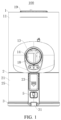
FIG. 1 is a side view of a hand-held vacuum cleaner according to an embodiment of the present disclosure. -
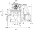
FIG. 2 is a cross-sectional view of a hand-held vacuum cleaner according to an embodiment of the present disclosure. -
FIG. 3 is an enlarged view of part A inFIG. 2 . -
FIG. 4 is an enlarged view of part B inFIG. 2 . -
FIG. 5 is an exploded view of a hand-held vacuum cleaner according to an embodiment of the present disclosure. -
FIG. 6 is another exploded view of a hand-held vacuum cleaner according to an embodiment of the present disclosure viewed in another direction. -
FIG. 7 is an exploded cross-sectional view of a hand-held vacuum cleaner according to an embodiment of the present disclosure. - Embodiments of the present disclosure will be described in detail below with reference to examples thereof as illustrated in the accompanying drawings, throughout which same or similar elements, or elements having same or similar functions, are denoted by same or similar reference numerals. The embodiments described below with reference to the drawings are illustrative only, and are intended to explain, rather than limiting, the present disclosure.
- In the description of the present disclosure, it should be understood that, the orientation or the position indicated by terms such as "center", "longitudinal", "lateral", "length", "width", "thickness", "over", "below", "front", "rear", "left", "right", "vertical", "horizontal", "top", "bottom", "inner", "outer", "clockwise", "anti-clockwise", "axial", "radial", and "circumferential" should be construed to refer to the orientation and the position as shown in the drawings, and is only for the convenience of describing the present disclosure and simplifying the description, rather than indicating or implying that the pointed device or element must have a specific orientation, or be constructed and operated in a specific orientation, and therefore cannot be understood as a limitation of the present disclosure. In addition, features associated with "first" and "second" may explicitly or implicitly comprise one or more of these features. In the description of the present disclosure, "a plurality of" means two or more, unless otherwise specified.
- A hand-held
vacuum cleaner 100 according to the embodiments of the present disclosure will be described below with reference toFIG. 1 to FIG. 7 . - As illustrated in
FIG. 1 to FIG. 7 , the hand-heldvacuum cleaner 100 according to the embodiments of the present disclosure comprises amachine body 1 and adust cup assembly 2. Themachine body 1 comprises afan 12 and ahousing 11. Thefan 12 is disposed in thehousing 11. Preferably, thefan 12 may be a centrifugal fan. - The
housing 11 is provided with aconnection assembly 13. Theconnection assembly 13 is provided with asuction air duct 14. Thesuction air duct 14 has ahousing air inlet 18 located at thehousing 11. Thehousing 11 may have ahousing air outlet 19 formed at thehousing 11. As illustrated inFIG. 2 , thehousing air inlet 18 may be formed at a front end of thehousing 11 inFIG. 2 , and thehousing air outlet 19 may be formed at an upper end of thehousing 11 inFIG. 2 . It should be understood that air inside thehousing 11 may be compressed by thefan 12. In addition, thefan 12 may discharge the compressed air inside thehousing 11 out of thehousing 11 through thehousing air outlet 19. A negative pressure may be formed inside themachine body 1. Under the negative pressure inside themachine body 1, air may be supplied to thefan 12 after passing through, via thehousing air inlet 18, thesuction air duct 14 and thedust cup assembly 2 sequentially, to balance an air pressure of thefan 12. - The
machine body 1 is provided with a first engagement portion 151. Thedust cup assembly 2 comprises adust cup 21, afilter assembly 4, asecond engagement portion 22, and anactuator 23. Thedust cup 21 has anair inlet 24. Thefilter assembly 4 is removably provided in thedust cup 21. Each of thesecond engagement portion 22 and theactuator 23 is provided at thedust cup 21. Theactuator 23 is engaged with thesecond engagement portion 22. When being actuated, theactuator 23 can control thesecond engagement portion 22 to move to a disengagement position. At the disengagement position, thesecond engagement portion 22 is disengaged from thefirst engagement portion 15 to allow thedust cup assembly 2 to be removed. When thesecond engagement portion 22 is engaged with thefirst engagement portion 15, thedust cup assembly 2 is mounted to themachine body 1 and thesuction air duct 14 is in communication with theair inlet 24. - It should be noted that the hand-held vacuum cleaner further comprises a vacuum cleaner head (not illustrated). The vacuum cleaner head may move on a to-be-cleaned object, such as a floor, a sofa, or the like, to suck air with impurities such as dust. The vacuum cleaner head may be connected to the
connection assembly 13 by a tube, or may be mounted directly at theconnection assembly 13. The air with impurities is sucked through the vacuum cleaner head. For the convenience of description, the air sucked through the hand-heldvacuum cleaner 100 is described below as dusty air. However, it should be understood that the air sucked through the hand-heldvacuum cleaner 100 carries not only dust but also impurities such as hair. - In some embodiments, when the hand-held
vacuum cleaner 100 is turned on, the dusty air is sucked through the vacuum cleaner head. When flowing into themachine body 1, the dusty air needs to pass through thedust cup assembly 2. When the dusty air passes through thedust cup assembly 2, the dust in the dusty air may stay in the filter assembly after being filtered by the filter assembly. After the dusty air is filtered by thefilter assembly 4, the dust may stay in thedust cup 21, while clean air may flow out of thedust cup assembly 2 through anair outlet 29 of thedust cup assembly 2 opposite to thehousing air outlet 19. The clean air may be compressed by thefan 12 and then flow out of themachine body 1 through thehousing air outlet 19. Therefore, dust vacuuming can be implemented by the hand-heldvacuum cleaner 100. - The
dust cup assembly 2 is removably mounted at themachine body 1. Themachine body 1 has a mounting position at which thedust cup assembly 2 may be mounted. Thedust cup assembly 2 may be removed from themachine body 1 when thedust cup assembly 2 needs to be cleaned or dusted. Themachine body 1 is provided with thefirst engagement portion 15, and thedust cup 21 is provided with thesecond engagement portion 22. Thesecond engagement portion 22 may be selectively engaged with thefirst engagement portion 15. Theactuator 23 is connected to thesecond engagement portion 22. Further, theactuator 23 can control thesecond engagement portion 22 to move between the disengagement position and a locking position. When thedust cup assembly 2 needs to be removed, by trigging theactuator 23 disposed at thedust cup 21, theactuator 23 can drive thesecond engagement portion 22 to move from the locking position to the disengagement position to unlock thedust cup assembly 2 from themachine body 1. Thedust cup assembly 2 may be removed from themachine body 1 in an unlocked state. A user can clean or dust the removeddust cup assembly 2. - Since the
filter assembly 4 is removably disposed in thedust cup 21, thedust cup 21 and thefilter assembly 4 may be disengaged from themachine body 1 simultaneously when thedust cup assembly 2 is removed from themachine body 1. As a result, a disassembly and cleaning of the hand-heldvacuum cleaner 100 can be simplified. In addition, the user is free from worrying about an escape of the dust from thedust cup 21 and/or thefilter assembly 4 when removing thedust cup assembly 2 from themachine body 1, which improves the user's product satisfaction with the hand-heldvacuum cleaner 100. - It should also be noted that, the dust cup assembly in some hand-held vacuum cleaners in the related art is also removable. However, the dust cup assembly is connected to a connection assembly engaged with the vacuum cleaner head. Therefore, after the removing, the dust cup assembly cannot be cleaned directly due to a presence of the connection assembly. In addition, the dust cup assembly has a heavy overall weight, which makes it uneasy to be removed.
- With the hand-held
vacuum cleaner 100 according to the embodiments of the present disclosure, theconnection assembly 13 connected to the vacuum cleaner head is disposed at thehousing 11. When the dust needs to be removed, thedust cup assembly 2 is detached. Thedust cup assembly 2 is provided with no connection assembly. Instead, the removable filter assembly is disposed in the dust cup to integrate the dust cup assembly. Therefore, the entire dust cup assembly can be removed for cleaning, which facilitates removal of the dust. In addition, compared with the dust cup assembly in the related art, the dust cup assembly has a lighter weight, which facilitates a detachment of the dust cup assembly. - It should be understood that, after the dust cup assembly is removed, the filter assembly may also be removed from the dust cup for cleaning or replacement.
- After the
dust cup assembly 2 is cleaned or dusted, thedust cup assembly 2 may be mounted at the mounting position by assembling thedust cup assembly 2 with themachine body 1. In addition, theactuator 23 is not actuated when assembling thedust cup assembly 2 with themachine body 1, and thus thesecond engagement portion 22 is returned to the locking position to be engaged with thefirst engagement portion 15, to lock thedust cup assembly 2 at themachine body 1. As a result, thedust cup assembly 2 can be fixed to themachine body 1. Thedust cup assembly 2 at the mounting position may be in communication with thesuction air duct 14. The dusty air in thesuction air duct 14 may enter thedust cup assembly 2 through theair inlet 24 for filtration. - With the hand-held vacuum cleaner according to the embodiments of the present disclosure, the dust cup with the filter assembly may be removed from the
machine body 1 for cleaning, which not only simplifies the removing of the dust cup assembly, but also prevents the dust and other impurities from escaping from the dust cup and/or the filter assembly. Also, the entire dust cup assembly can be removed for cleaning, which facilitates the removal of the dust. In addition, with the actuator and the first engagement portion, the actuator when being actuated can separate thesecond engagement portion 22 from thefirst engagement portion 15 to enable a removal of thedust cup assembly 2, facilitating the removing of thedust cup assembly 2. - In some embodiments of the present disclosure, as illustrated in
FIG. 2 ,FIG. 3 , andFIG. 5 toFIG. 7 , thefirst engagement portion 15 may be a snapping groove formed at thehousing 11. Thesecond engagement portion 22 may be a snapping hook. When theactuator 23 is pressed, the snapping hook may move away from the snapping groove and may be disengaged from the snapping groove. It should be noted that, as illustrated inFIG. 2 , a direction in which the snapping hook moves away from the snapping groove may refer to a forward direction inFIG. 2 . When the snapping hook is engaged with the snapping groove in a snap manner, a part of the snapping hook may extend into the snapping groove. The part of the snapping hook extending into the snapping groove may abut with the snapping groove. The snapping groove is adapted to restrict a movement of the snapping hook in a height direction of the hand-heldvacuum cleaner 100. The height direction of the hand-heldvacuum cleaner 100 may refer to an up-down direction inFIG. 2 . At a locking position, the snapping hook cannot be disengaged from the snapping groove. The snapping hook may be connected to thedust cup assembly 2, and the snapping groove can restrict a movement of thedust cup assembly 2 by the snapping hook. Therefore, thedust cup assembly 2 is fixedly connected to themachine body 1. - In addition, when being pressed, the
actuator 23 can drive the snapping hook to move away from the snapping groove. When being at a position away from the snapping groove, the snapping hook does not abut with the snapping groove, and thus the snapping groove cannot restrict the movement of the snapping hook in the height direction of the hand-heldvacuum cleaner 100. The snapping groove cannot restrict the movement of thedust cup assembly 2 by the snapping hook. As a result, thedust cup assembly 2 can move relative to themachine body 1 in the height direction of the hand-heldvacuum cleaner 100. In this case, thedust cup assembly 2 can be removed from themachine body 1. Thus, fixing and removing of the dust cup assembly can be achieved by means of the engagement between the snapping hook and the snapping groove. Therefore, the engagement relation is simple and reliable. - In some embodiments of the present disclosure, the
second engagement portion 22 may be constructed as an elastic snapping hook. During an assembly of thesecond engagement portion 22, thesecond engagement portion 22 may be configured to be assembled in the snapping groove through compression and deformation. When the elastic snapping hook is assembled with the snapping groove in place, the elastic snapping hook may restore its deformation and collide with the snapping groove. The elastic snapping hook may make an alert when colliding with the snapping groove. An end of the snapping groove may be provided with afirst guide portion 110. Accordingly, an end of the elastic snapping hook may be provided with asecond guide portion 210. As illustrated inFIG. 2 , the end of the snapping groove provided with thefirst guide portion 110 may refer to a bottom end of the snapping groove inFIG. 2 , and the end of the elastic snapping hook provided with thesecond guide portion 210 may refer to a top end of the elastic snapping hook. Thefirst guide portion 110 and thesecond guide portion 210 may cooperate with each other in a guiding manner. - Preferably, each of the
first guide portion 110 and thesecond guide portion 210 may be constructed as an inclined surface. During the assembly of thesecond engagement portion 22, thefirst guide portion 110 is adapted to abut with thesecond guide portion 210. Thesecond guide portion 210 may move along a surface of thefirst guide portion 110. Thefirst guide portion 110 may drive the elastic snapping hook to be compressed and deformed. The elastic snapping hook, when being compressed and deformed, may move away from the snapping groove. When a height position of thesecond guide portion 210 exceeds a height position of thefirst guide portion 110, the elastic snapping hook may extend into the snapping groove under an elastic force, and the snapping groove may limit a position of the elastic snapping hook. When the elastic snapping hook is assembled in the snapping groove in place, a surface of the elastic snapping hook close to the snapping groove may collide with the snapping groove. The snapping groove may generate an impact sound when subjected to a collision. The impact sound may be set as the alert. The alert may remind the user that thedust cup assembly 2 and themachine body 1 are assembled in place. By setting the alert during the assembling of thedust cup assembly 2 with themachine body 1, the alert can remind the user whether thedust cup assembly 2 and themachine body 1 are assembled in place. In this way, it is possible to prevent thedust cup assembly 2 from falling off from themachine body 1 during use of the hand-heldvacuum cleaner 100 due to a failure to mount thedust cup assembly 2 in position, which in turn improves operation stability of the hand-heldvacuum cleaner 100. - In some embodiments of the present disclosure, as illustrated in
FIG. 2 ,FIG. 3 , andFIG. 7 , aseal 16 may be disposed at the end of thesuction air duct 14. Theseal 16 may be formed into a ring structure. Theseal 16 may be in contact with thedust cup assembly 2 when thedust cup assembly 2 is mounted to themachine body 1. Preferably, theseal 16 may be a rubber member. Theseal 16 may be disposed at an end of thesuction air duct 14 close to thedust cup assembly 2. As illustrated inFIG. 2 , the end of thesuction air duct 14 close to thedust cup assembly 2 may refer to a rear end of thesuction air duct 14 inFIG. 2 . Theseal 16 may extend in an axial direction of thesuction air duct 14. The axial direction of thesuction air duct 14 may refer to a front-rear direction inFIG. 2 . - In addition, the
seal 16 is adapted to abut with thedust cup assembly 2. When themachine body 1 is assembled with thedust cup assembly 2, thedust cup assembly 2 may compress theseal 16. Theseal 16 is deformed when compressed. Further, theseal 16 may seal a gap between theair inlet 24 and thesuction air duct 14. When the hand-heldvacuum cleaner 100 is in an operation state, the dusty air inside thesuction air duct 14 cannot flow into thehousing 11 through the gap between theair inlet 24 and thesuction air duct 14. Therefore, cleanliness and neatness in thehousing 11 can be ensured, which further improves a product quality of the hand-heldvacuum cleaner 100. - In some embodiments of the present disclosure, as illustrated in
FIG. 1 to FIG. 3 andFIG. 5 to FIG. 7 , theactuator 23 and theconnection assembly 13 are located on one side of the hand-heldvacuum cleaner 100. Each of theactuator 23 and theconnection assembly 13 may be disposed at a front side of the hand-heldvacuum cleaner 100. It should be noted that ahandle 111 may be further disposed at a rear side of thehousing 11. Thehandle 111 may be held by the user to operate the hand-heldvacuum cleaner 100. By arranging theconnection assembly 13 at the front side of the hand-heldvacuum cleaner 100, an opening direction of thehousing air inlet 18 formed at theconnection assembly 13 may be directed towards a front side of the user when the hand-heldvacuum cleaner 100 held by the user, which facilitates mounting the vacuum cleaner head by the user. In addition, by arranging theactuator 23 at the front side of the hand-heldvacuum cleaner 100, interference between the actuator 23 and thehandle 111 can be avoided, and an actuating region of theactuator 23 can be enlarged. In this way, thedust cup assembly 2 can be easily unlocked by the user through theactuator 23, which in turn can improve the user's satisfaction with the hand-heldvacuum cleaner 100. - In some embodiments of the present disclosure, as illustrated in
FIG. 1 ,FIG. 2 , andFIG. 4 toFIG. 7 , thedust cup 21 may comprise acup body 25 and anend cover 3. Thefilter assembly 4 may be provided in thecup body 25. Each of theactuator 23 and thesecond engagement portion 22 may be provided at thecup body 25. Adust outlet 26 may be formed at a bottom of thecup body 25. Theend cover 3 is movably provided at thedust outlet 26. Theend cover 3 can expose or cover the dust outlet. Preferably, a deformableelastic piece 6 is provided between the actuator 23 and thecup body 25. Theactuator 23, theelastic piece 6, and thesecond engagement portion 22 may be integrally formed. When the user presses theactuator 23, theelastic piece 6 may be compressed and elastically deformed, and theactuator 23 can drive thesecond engagement portion 22 to move away from the snapping groove. That is, thesecond engagement portion 22 can move from the locking position to the disengagement position. Thedust cup assembly 2 may be removed from themachine body 1 when being unlocked. - When the user stops compressing the actuator, the
elastic piece 6 is restored under the elastic force. During the restoring of theelastic piece 6, theelastic piece 6 can drive thesecond engagement portion 22 to move towards the snapping groove to be restored. The user may then mount thedust cup assembly 2 onto themachine body 1, during which thesecond engagement portion 22 is compressed and deformed to be assembled in the snapping groove. When the elastic snapping hook is assembled with the snapping groove in place, the elastic snapping hook may restore its deformation and collide with the snapping groove. The elastic snapping hook may make the alert when colliding with the snapping groove. That is, thesecond engagement portion 22 may move from the disengagement position to the locking position, and thedust cup assembly 2 may be fixed to themachine body 1 when being locked. Compared with an actuator of an electronic control structure, theactuator 23 of a mechanical structure has high operation reliability, and is unlikely to be damaged. Further, theactuator 23 operates without being energized. - In addition, by arranging the
filter assembly 4 in thecup body 25, thefilter assembly 4 and thecup body 25 may be integrated. When the dusty air enters thecup body 25, thefilter assembly 4 can separate the air from the dust. The dust separated from the air may be accumulated in thecup body 25. After the hand-heldvacuum cleaner 100 operates for a long period of time, too much dust is accumulated in thecup body 25, which would affect dust vacuuming performance of the hand-heldvacuum cleaner 100. By forming thedust outlet 26 at the bottom of thecup body 25, thedust outlet 26 may communicate thecup body 25 and an ambient environment. The dust in thecup body 25 may be poured out from thedust outlet 26 to reduce a volume of the dust in thecup body 25. - In addition, in order to cover the
dust outlet 26 when the hand-heldvacuum cleaner 100 vacuums the dust, and in order to expose thedust outlet 26 when the dust is removed from the hand-heldvacuum cleaner 100, theend cover 3 is disposed at the bottom of thecup body 25. Theend cover 3 is adapted to cover thedust outlet 26. In addition, theend cover 3 may selectively expose thedust outlet 26. In some embodiments, a pivot hole is formed at each of theend cover 3 and thecup body 25. A pivot shaft may pass through the pivot hole of theend cover 3 and the pivot hole of thecup body 25 sequentially to connect theend cover 3 to thecup body 25. Theend cover 3 is rotatable about a central axis of the pivot shaft. When theend cover 3 is rotated away from thedust outlet 26, theend cover 3 can expose thedust outlet 26, and the dust can be poured out through thedust outlet 26. When theend cover 3 is rotated towards thedust outlet 26, theend cover 3 can cover thedust outlet 26. The covereddust outlet 26 can close thedust cup assembly 2 to prevent the dust from escaping from thedust cup assembly 2 during the operation of the hand-heldvacuum cleaner 100. - In some embodiments of the present disclosure, as illustrated in
FIG. 1 ,FIG. 2 , andFIG. 4 toFIG. 7 , thedust cup assembly 2 may further comprise athird engagement portion 31, afourth engagement portion 27, and adust discharging member 5. Theend cover 3 may be connected to thecup body 25. Further, an end of theend cover 3 is rotatable with respect tocup body 25. Thethird engagement portion 31 may be disposed at another end of theend cover 3. The end of theend cover 3 rotatable with respect to thecup body 25 may refer to a rear end of thecup body 25 inFIG. 2 . The other end of theend cover 3 provided with thethird engagement portion 31 may refer to a front end of thecup body 25 inFIG. 2 . Thecup body 25 may be provided with thefourth engagement portion 27. Thethird engagement portion 31 may be disengaged from or engaged with thefourth engagement portion 27. Thefourth engagement portion 27 may further be connected to thedust discharging member 5. When being actuated, thedust discharging member 5 can control thethird engagement portion 31 to be disengaged from thefourth engagement portion 27. After thethird engagement portion 31 is disengaged from thefourth engagement portion 27, theend cover 3 may be opened. The pivot hole of theend cover 3 may be formed at a rear end of theend cover 3. The pivot hole of thecup body 25 may be formed at the rear end of thecup body 25. The rear end of thecup body 25 is rotatable about the central axis of the pivot shaft to expose or cover thedust outlet 26 by theend cover 3. - In addition, when the
third engagement portion 31 is engaged with thefourth engagement portion 27, thethird engagement portion 31 and thefourth engagement portion 27 may lock theend cover 3, and thus thedust outlet 26 cannot be exposed by theend cover 3. In this way, it is possible to ensure that no dust will escape from thedust cup assembly 2. When thethird engagement portion 31 is disengaged from thefourth engagement portion 27, thethird engagement portion 31 and thefourth engagement portion 27 may unlock theend cover 3, and thus theend cover 3 may rotate about the central axis of the pivot shaft and expose thedust outlet 26. In this way, the dust can be poured out through thedust outlet 26. Thedust discharging member 5 may control thefourth engagement portion 27 to be engaged with thethird engagement portion 31. Also, thedust discharging member 5 may control thefourth engagement portion 27 to be disengaged from thethird engagement portion 31. - In some embodiments, when pressed by the user, the
dust discharging member 5 may be actuated. The actuateddust discharging member 5 may drive thefourth engagement portion 27 to be disengaged from thethird engagement portion 31. Thefourth engagement portion 27 may unlock theend cover 3 when being disengaged from thethird engagement portion 31. When the user stops pressing thedust discharging member 5, thedust discharging member 5 may be restored. Thedust discharging member 5 during the restoring may drive thefourth engagement portion 27 to be engaged with thethird engagement portion 31. Thefourth engagement portion 27 may lock the end cover after being engaged with thethird engagement portion 31. - It should be understood that the
dust discharging member 5 may be configured to only control thefourth engagement portion 27 to be disengaged from thethird engagement portion 31. Theend cover 3 may be driven by the user to rotate towards the dust outlet to engage thefourth engagement portion 27 with thethird engagement portion 31. - Further, as illustrated in
FIG. 1 ,FIG. 2 , andFIG. 4 toFIG. 7 , thefourth engagement portion 27 may be engaged with thethird engagement portion 3 in a hooking manner. When thedust discharging member 5 is pressed, thefourth engagement portion 27 can move away from thethird engagement portion 31. As a result, thefourth engagement portion 27 is disengaged from thethird engagement portion 31. Thethird engagement portion 31 may be formed as a first snapping hook. Thefourth engagement portion 27 may be formed as a second snapping hook. The first snapping hook may have afirst engagement surface 32. The second snapping hook may have asecond engagement surface 211. Thefirst engagement surface 32 is adapted to be engaged with thesecond engagement surface 211. When thefourth engagement portion 27 is engaged with thethird engagement portion 31 in the hooking manner, thefirst engagement surface 32 and thesecond engagement surface 211 may be limited relative to each other in the height direction of the hand-heldvacuum cleaner 100. As a result, theend cover 3 is locked by thefourth engagement portion 27. When thefourth engagement portion 27 is disengaged from thethird engagement portion 31, thefirst engagement surface 32 is disengaged from thesecond engagement surface 211. As a result, thefirst engagement surface 32 and thesecond engagement surface 211 are no longer limited relative to each other. Thus, thefirst engagement surface 32 can move relative to thesecond engagement surface 211 to unlock theend cover 3. - In some embodiments of the present disclosure, as illustrated in
FIG. 1 to FIG. 7 , both theactuator 23 and thedust discharging member 5 may be located at one side of thedust cup 21. As illustrated inFIG. 2 , both theactuator 23 and thedust discharging member 5 may be disposed at a front end of thedust cup 21. A front-rear direction of thedust cup 21 may refer to the front-rear direction inFIG. 2 . In addition, theactuator 23 may be spaced apart from thedust discharging member 5 in a height direction of thedust cup 21. The height direction of thedust cup 21 may refer to the up-down direction inFIG. 2 . Theelastic piece 6 may be provided between the actuator 23 and the cup body and between thedust discharging member 5 and the cup body. When being pressed, theactuator 23 may be actuated. The actuatedactuator 23 may unlock thedust cup assembly 2 to allow thedust cup assembly 2 to be removed from themachine body 1. When being pressed, thedust discharging member 5 may be actuated, and thedust outlet 26 may be exposed. In this case, the dust in thedust cup assembly 2 can be poured out through thedust outlet 26. - In addition, a surface of each of the
actuator 23 and thedust discharging member 5 may be provided with a function identifier. The function identifier may be used to remind the user of functions of theactuator 23 and thedust discharging member 5. For example, the surface of theactuator 23 may be provided with a removing identifier that may remind the user to unlock thedust cup assembly 2 by pressing theactuator 23. For example, the surface of thedust discharging member 5 may be provided with a dust discharging identifier that may remind the user to expose thedust outlet 26 by pressing thedust discharging member 5. The function identifiers provided at the surface of theactuator 23 and the surface of thedust discharging member 5 can avoid mis-operation from the user. - In some embodiments of the present disclosure, as illustrated in
FIG. 4 ,FIG. 5 , andFIG. 7 , thedust cup 21 may be provided with asecond positioning portion 28, and themachine body 1 may be provided with afirst positioning portion 17. When thedust cup assembly 2 is connected to themachine body 1, thefirst positioning portion 17 may be engaged with and connected to thesecond positioning portion 28. Thedust cup assembly 2 can be positioned by engaging thefirst positioning portion 17 with thesecond positioning portion 28. One of thefirst positioning portion 17 and thesecond positioning portion 28 may be formed as a positioning protrusion, while the other one of thefirst positioning portion 17 and thesecond positioning portion 28 may be formed as a positioning groove. Preferably, thefirst positioning portion 17 may be formed as the positioning groove, and thesecond positioning portion 28 may be formed as the positioning protrusion. The positioning protrusion may extend into the positioning groove. The positioning protrusion is adapted to abut with a groove wall of the positioning groove. The positioning groove may be configured to restrict a rotation of the positioning protrusion in a circumferential direction of thedust cup assembly 2. Thesecond positioning portion 28 may be disposed at thedust cup 21. That is, the positioning groove may be configured to restrict the rotation of thedust cup assembly 2 by means of the positioning protrusion, which can ensure that theair inlet 24 is in communication with thesuction air duct 14. When theair inlet 24 is kept in communication with thesuction air duct 14, the dusty air can be allowed to flow into thedust cup assembly 2 for a dust-air separation. An engagement between thefirst positioning portion 17 and thesecond positioning portion 28 can ensure a normal operation of the hand-heldvacuum cleaner 100. - In some embodiments of the present disclosure, as illustrated in
FIG. 2 andFIG. 4 toFIG. 7 , thefilter assembly 4 may comprise acyclone separator 41. Thecyclone separator 41 is disposed in thedust cup 21. Further, thecyclone separator 41 is removably connected to thedust cup 21. Theair inlet 24 may be formed at a circumferential side of thecyclone separator 41. Thecyclone separator 41 is configured to filter the dust from the dusty air. Thecyclone separator 41 may be formed into a cylindrical structure. In addition, anair cavity 44 may be defined in thecyclone separator 41. Theair cavity 44 may be in communication with theair outlet 29. A central axis of thecyclone separator 41 may be coaxial with a central axis of thedust cup 21. Further, thecyclone separator 41 may extend in a height direction of thedust cup assembly 2. A bottom end of thecyclone separator 41 may abut with theend cover 3. An outer wall of thecyclone separator 41 may be spaced apart from an inner wall of thedust cup 21. Afiltration space 45 may be formed between the outer wall of thecyclone separator 41 and the inner wall of thedust cup 21. Thecyclone separator 41 may have at least oneair passage hole 43 formed at a surface of thecyclone separator 41. The at least oneair passage hole 43 may communicate theair cavity 44 and thefiltration space 45. The filtered air may flow from thefiltration space 45 into theair cavity 44. The air in theair cavity 44 may flow out of thedust cup assembly 2 through theair outlet 29. - The
dust cup assembly 2 may be provided with a mounting portion at theair outlet 29. The mounting portion may be configured for mounting of thecyclone separator 41. Thecyclone separator 41 may extend from theair outlet 29 into thedust cup 21. Further, thecyclone separator 41 may be connected to the mounting portion. When entering thedust cup 21 from theair inlet 24 in a tangential direction of thedust cup 21, the dusty air may rotate and flow in a circumferential direction of thecyclone separator 41 along the inner wall of thedust cup 21 and the outer wall of thecyclone separator 41. In this way, the dust in the dusty air can be separated from the dusty air and may stay in thefiltration space 45. When thedust outlet 26 is exposed, the dust may be poured out of thefiltration space 45. Exposing thedust outlet 26 can prevent an excessive accumulation of dust in thefiltration space 45 from affecting dust vacuuming performance of the hand-heldvacuum cleaner 100. The filtered air may flow into theair cavity 44 from theair passage hole 43. Therefore, dust-air separation can be realized. - It should be noted that the
air cavity 44 may also have asecond separator 46 provided in theair cavity 44. Thesecond separator 46 may be connected to thecyclone separator 41. Thecyclone separator 41 may be constructed into a conical structure at a lower end of theair cavity 44. Adust storage space 47 may be defined between a bottom of the conical structure and theend cover 3. After the air is subjected to a primary dust removal in thefiltration space 45 and enters theair cavity 44, the air may be subjected to a secondary dust removal by thesecond separator 46 to be further separated from the dust. In this way, the dust can be effectively blocked by thedust cup assembly 2, and clogging of theair outlet 29 can also be avoided. The dust separated from the air may fall into thedust storage space 47 along the conical structure. When thedust outlet 26 is exposed, the dust may be poured out of thedust storage space 47. Exposing thedust outlet 26 can prevent an excessive accumulation of dust in thedust storage space 47 from affecting the dust vacuuming performance of the hand-heldvacuum cleaner 100. - Further, the
filter assembly 4 may further comprisefilter cotton 42. Thefilter cotton 42 may be disposed at an air outlet end of thecyclone separator 41. Further, thefilter cotton 42 is removably connected to thecyclone separator 41. The air outlet end of thecyclone separator 41 may be opposite to theair outlet 29 of thedust cup assembly 2. As illustrated inFIG. 2 , the air outlet end of thecyclone separator 41 may refer to an upper end of thecyclone separator 41 inFIG. 2 . The air outlet end of thecyclone separator 41 may be in communication with theair cavity 44. The filtered air in theair cavity 44 may be discharged out of thedust cup assembly 2 from the air outlet end of thecyclone separator 41. A mounting groove may be formed at the air outlet end of thecyclone separator 41. Thefilter cotton 42 may be mounted in the mounting groove and configured to cover the air outlet end of thecyclone separator 41. When the air flows from theair cavity 44 towards thefan 12, thefilter cotton 42 may block residual dust in the air. Therefore, clogging of thefan 12 and/or thehousing air outlet 19 can be avoided by thefilter cotton 42, thereby improving the operation stability of the hand-heldvacuum cleaner 100. - In addition, the
filter cotton 42 may have a specific structure that thefilter cotton 42 may be filled with a cotton material. The cotton material is configured to filter out and absorb the dust. An end of thefilter cotton 42 close to thefan 12 may allow passage of the air and block the dust. It should be noted that the end of thefilter cotton 42 close to thefan 12 may refer to an upper end of thefilter cotton 42 inFIG. 2 . An end of thefilter cotton 42 close to thecyclone separator 41 may have a plurality of holes through which the air may enter thefilter cotton 42 for filtration. The end of thefilter cotton 42 close to thecyclone separator 41 may refer to a lower end of thefilter cotton 42 inFIG. 2 . After the hand-heldvacuum cleaner 100 has vacuumed for a long period of time, thefilter cotton 42 may be removed from thefilter assembly 4 for cleaning to ensure satisfying filterability of thefilter cotton 42. Thefilter cotton 42 may also be provided with a carrying handle. The carrying handle is configured to help the user remove thefilter cotton 42 from thefilter assembly 4, optimizing use experience of the hand-heldvacuum cleaner 100 for the user. - Reference throughout this specification to "an embodiment", "some embodiments", "an illustrative embodiment", "an example", "a specific example", or "some examples" means that a particular feature, structure, material, or characteristic described in connection with the embodiment or example is comprised in at least one embodiment or example of the present disclosure. The appearances of the above phrases in various places throughout this specification are not necessarily referring to the same embodiment or example. Furthermore, the particular features, structures, materials, or characteristics may be combined in any suitable manner in one or more embodiments or examples.
- Although embodiments of the present disclosure have been illustrated and described, it is conceivable for those skilled in the art that various changes, modifications, replacements, and variations can be made to these embodiments without departing from the principles and spirit of the present disclosure. The scope of the present disclosure shall be defined by the claims as appended and their equivalents.
Claims (12)
- A hand-held vacuum cleaner, comprising:a machine body comprising a housing and a fan provided in the housing, the housing having a connection assembly provided at the housing, the connection assembly having a suction air duct provided in the connection assembly, and the machine body having a first engagement portion provided at the machine body; anda dust cup assembly comprising a dust cup, a filter assembly, a second engagement portion, and an actuator, the dust cup having an air inlet, the filter assembly being removably provided in the dust cup, each of the second engagement portion and the actuator being provided at the dust cup, the actuator being engaged with the second engagement portion to control the second engagement portion to move to a disengagement position when the actuator is actuated, wherein at the disengagement position, the second engagement portion is disengaged from the first engagement portion to allow the dust cup assembly to be removed, and wherein when the second engagement portion is engaged with the first engagement portion, the dust cup assembly is mounted to the machine body and the suction air duct is in communication with the air inlet.
- The hand-held vacuum cleaner according to claim 1, wherein:the first engagement portion is a snapping groove formed at the housing;the second engagement portion is a snapping hook; andwhen the actuator is pressed, the snapping hook moves away from the snapping groove to be disengaged from the snapping groove.
- The hand-held vacuum cleaner according to claim 2, wherein the second engagement portion is an elastic snapping hook; and
the second engagement portion is compressed and deformed to be assembled in the snapping groove during an assembly, and restores the deformation after being assembled in place and collide with the snapping groove to make an alert. - The hand-held vacuum cleaner according to any one of claims 1 to 3, wherein the suction air duct has an end provided with a seal of a ring shape, the dust cup assembly being in contact with the seal when the dust cup assembly is mounted to the machine body.
- The hand-held vacuum cleaner according to any one of claims 1 to 4, wherein the connection assembly and the actuator are located on a same side of the hand-held vacuum cleaner.
- The hand-held vacuum cleaner according to any one of claims 1 to 5, wherein the dust cup comprises:a cup body, the filter assembly being disposed in the cup body, each of the second engagement portion and the actuator being disposed at the cup body, and the cup body having a dust outlet formed at a bottom of the cup body; andan end cover movably provided at the dust outlet to cover or expose the dust outlet.
- The hand-held vacuum cleaner according to claim 6, wherein the end cover has an end rotatably connected to the cup body and another end provided with a third engagement portion;a fourth engagement portion is provided at the cup body and disengaged from or engaged with the third engagement portion; anda dust discharging member is connected to the fourth engagement portion, the dust discharging member controls, when being actuated, the fourth engagement portion to be disengaged from the third engagement portion to expose the end cover.
- The hand-held vacuum cleaner according to claim 7, wherein:the third engagement portion is hooked and engaged with the fourth engagement portion; andwhen the dust discharging member is pressed, the fourth engagement portion moves away from the third engagement portion to be disengaged from the third engagement portion.
- The hand-held vacuum cleaner according to claim 7, wherein the dust discharging member and the actuator are located at a same side of the dust cup.
- The hand-held vacuum cleaner according to any one of claims 1 to 9, wherein the machine body has a first positioning portion provided at the machine body;the dust cup has a second positioning portion provided at the dust cup; andwhen the dust cup assembly is mounted to the machine body, the first positioning portion is engaged with the second positioning portion to position the dust cup assembly.
- The hand-held vacuum cleaner according to any one of claims 1 to 10, wherein the filter assembly comprises:
a cyclone separator removably provided in the dust cup, the air inlet being located at a circumferential side of the cyclone separator. - The hand-held vacuum cleaner according to claim 11, wherein the filter assembly further comprises filter cotton removably provided at an air outlet end of the cyclone separator.
Applications Claiming Priority (2)
| Application Number | Priority Date | Filing Date | Title |
|---|---|---|---|
| CN202110559641.0A CN115363470A (en) | 2021-05-21 | 2021-05-21 | Hand-held vacuum cleaner |
| PCT/CN2022/080201 WO2022242275A1 (en) | 2021-05-21 | 2022-03-10 | Hand-held vacuum cleaner |
Publications (1)
| Publication Number | Publication Date |
|---|---|
| EP4335339A1 true EP4335339A1 (en) | 2024-03-13 |
Family
ID=84058538
Family Applications (1)
| Application Number | Title | Priority Date | Filing Date |
|---|---|---|---|
| EP22803604.2A Pending EP4335339A1 (en) | 2021-05-21 | 2022-03-10 | Hand-held vacuum cleaner |
Country Status (3)
| Country | Link |
|---|---|
| EP (1) | EP4335339A1 (en) |
| CN (1) | CN115363470A (en) |
| WO (1) | WO2022242275A1 (en) |
Family Cites Families (5)
| Publication number | Priority date | Publication date | Assignee | Title |
|---|---|---|---|---|
| GB2448915B (en) * | 2007-05-03 | 2011-07-13 | Dyson Technology Ltd | A collecting chamber for a cleaning appliance |
| CN106618374B (en) * | 2017-02-24 | 2022-04-08 | 江苏美的清洁电器股份有限公司 | Hand-held vacuum cleaner |
| CN212037366U (en) * | 2019-12-25 | 2020-12-01 | 浙江东亿磁业有限公司 | Hand-held type dust catcher |
| CN212382571U (en) * | 2020-03-27 | 2021-01-22 | 莱克电气股份有限公司 | Dust cup and handheld dust collector with same |
| CN214856357U (en) * | 2021-05-21 | 2021-11-26 | 江苏美的清洁电器股份有限公司 | Hand-held vacuum cleaner |
-
2021
- 2021-05-21 CN CN202110559641.0A patent/CN115363470A/en active Pending
-
2022
- 2022-03-10 EP EP22803604.2A patent/EP4335339A1/en active Pending
- 2022-03-10 WO PCT/CN2022/080201 patent/WO2022242275A1/en active Application Filing
Also Published As
| Publication number | Publication date |
|---|---|
| WO2022242275A1 (en) | 2022-11-24 |
| CN115363470A (en) | 2022-11-22 |
Similar Documents
| Publication | Publication Date | Title |
|---|---|---|
| US11503970B2 (en) | Vacuum cleaner | |
| EP1733670B1 (en) | Improvements in vacuum cleaners | |
| US6994739B2 (en) | Filter mounting device for vacuum cleaner | |
| US7074248B2 (en) | Filter cleaning device of cyclone vacuum cleaner | |
| KR101144756B1 (en) | A collecting chamber for a cleaning appliance | |
| EP1495710B1 (en) | Vacuum cleaner | |
| GB2506531A (en) | Vacuum cleaner | |
| EP4335339A1 (en) | Hand-held vacuum cleaner | |
| CN214856357U (en) | Hand-held vacuum cleaner | |
| JP5488204B2 (en) | Cyclone separation device and vacuum cleaner provided with the same | |
| JP7012420B2 (en) | Vacuum cleaner | |
| KR100767662B1 (en) | Filter Installation Structure for Dust Collector used Cyclone | |
| CN112741530A (en) | Vacuum cleaner | |
| KR20060107625A (en) | A dust collector for vacuum clearner | |
| KR101072682B1 (en) | Vacuum Cleaner | |
| CN113271832B (en) | Electric vacuum cleaner | |
| CN111938500B (en) | Electric vacuum cleaner and dust collecting device thereof | |
| JP7153708B2 (en) | Vacuum cleaner and its dust collector | |
| JP7174654B2 (en) | vacuum cleaner | |
| JP7085424B2 (en) | Vacuum cleaner | |
| JP6731317B2 (en) | Vacuum cleaner dust collector | |
| JP2024114582A (en) | Dust collectors and vacuum cleaners | |
| JP2024126175A (en) | Dust collectors and vacuum cleaners | |
| KR20020051792A (en) | Filter of fixing device for vacuum cleaner | |
| KR20060037988A (en) | Dust and dirt collecting unit for vacuum cleaner |
Legal Events
| Date | Code | Title | Description |
|---|---|---|---|
| STAA | Information on the status of an ep patent application or granted ep patent |
Free format text: STATUS: THE INTERNATIONAL PUBLICATION HAS BEEN MADE |
|
| PUAI | Public reference made under article 153(3) epc to a published international application that has entered the european phase |
Free format text: ORIGINAL CODE: 0009012 |
|
| STAA | Information on the status of an ep patent application or granted ep patent |
Free format text: STATUS: REQUEST FOR EXAMINATION WAS MADE |
|
| 17P | Request for examination filed |
Effective date: 20231206 |
|
| AK | Designated contracting states |
Kind code of ref document: A1 Designated state(s): AL AT BE BG CH CY CZ DE DK EE ES FI FR GB GR HR HU IE IS IT LI LT LU LV MC MK MT NL NO PL PT RO RS SE SI SK SM TR |
|
| DAV | Request for validation of the european patent (deleted) | ||
| DAX | Request for extension of the european patent (deleted) |