EP4334697B1 - Verfahren und vorrichtung zur durchführung von lastmessungen an vorrichtungen mit mehreren scharnieren - Google Patents
Verfahren und vorrichtung zur durchführung von lastmessungen an vorrichtungen mit mehreren scharnieren Download PDFInfo
- Publication number
- EP4334697B1 EP4334697B1 EP22725651.8A EP22725651A EP4334697B1 EP 4334697 B1 EP4334697 B1 EP 4334697B1 EP 22725651 A EP22725651 A EP 22725651A EP 4334697 B1 EP4334697 B1 EP 4334697B1
- Authority
- EP
- European Patent Office
- Prior art keywords
- hinged device
- plate
- drive arm
- actuator
- hinged
- Prior art date
- Legal status (The legal status is an assumption and is not a legal conclusion. Google has not performed a legal analysis and makes no representation as to the accuracy of the status listed.)
- Active
Links
Images


Classifications
-
- G—PHYSICS
- G01—MEASURING; TESTING
- G01M—TESTING STATIC OR DYNAMIC BALANCE OF MACHINES OR STRUCTURES; TESTING OF STRUCTURES OR APPARATUS, NOT OTHERWISE PROVIDED FOR
- G01M99/00—Subject matter not provided for in other groups of this subclass
- G01M99/007—Subject matter not provided for in other groups of this subclass by applying a load, e.g. for resistance or wear testing
-
- G—PHYSICS
- G01—MEASURING; TESTING
- G01L—MEASURING FORCE, STRESS, TORQUE, WORK, MECHANICAL POWER, MECHANICAL EFFICIENCY, OR FLUID PRESSURE
- G01L5/00—Apparatus for, or methods of, measuring force, work, mechanical power, or torque, specially adapted for specific purposes
- G01L5/0028—Force sensors associated with force applying means
-
- G—PHYSICS
- G01—MEASURING; TESTING
- G01M—TESTING STATIC OR DYNAMIC BALANCE OF MACHINES OR STRUCTURES; TESTING OF STRUCTURES OR APPARATUS, NOT OTHERWISE PROVIDED FOR
- G01M99/00—Subject matter not provided for in other groups of this subclass
- G01M99/008—Subject matter not provided for in other groups of this subclass by doing functionality tests
-
- G—PHYSICS
- G01—MEASURING; TESTING
- G01N—INVESTIGATING OR ANALYSING MATERIALS BY DETERMINING THEIR CHEMICAL OR PHYSICAL PROPERTIES
- G01N3/00—Investigating strength properties of solid materials by application of mechanical stress
- G01N3/32—Investigating strength properties of solid materials by application of mechanical stress by applying repeated or pulsating forces
- G01N3/34—Investigating strength properties of solid materials by application of mechanical stress by applying repeated or pulsating forces generated by mechanical means, e.g. hammer blows
Definitions
- This disclosure relates generally to materials testing, and more particularly, to methods and apparatus to perform load measurements on multi-hinged devices, and in particular to a hinged device testing system according to appended claim 1.
- Reliability testing for an assembly, or moving components of an assembly may involve repetitively performing intended and/or unintended movements of the components to verify that the components and/or assembly reliably operates for a defined minimum number of cycles of the movements.
- reliability testing of a flexible substrate may involve repeatedly flexing the substrate in one or more ways, while testing for continued operation of the device and/or monitoring various modes of failure.
- US 2019/391058A1 discloses a folding apparatus for flexible material durability testing.
- WO 2020/263502A1 discloses a flexible substrate testing system.
- CN 202 522 405U discloses a durability testing device for a hinge of an automotive side door.
- CN 106 388 389A discloses a foldable hidden type double bed.
- Flexible specimens often include assemblies and/or devices that have constraint mechanisms, such as simple hinges, double hinges, elliptical mechanisms, and/or other forms of constraints.
- constraint mechanisms such as simple hinges, double hinges, elliptical mechanisms, and/or other forms of constraints.
- Conventional measurement systems are not capable of characterizing forces associated with flexible specimens that involve such constraint mechanisms, because conventional measurement systems are not able to fold such specimens without over-constraining the specimens (resulting in damage), and/or because the reaction forces produced by the constraint mechanisms are typically many orders of magnitude greater than the reaction forces produced by the flexible material specimen.
- Disclosed example hinged device testing systems provide repetitive stress testing and/or load measurement for hinged devices having multiple hinges for 3 or more sections, while reducing or minimizing additional stress induced on the hinged device by the hinged device testing system itself.
- some disclosed hinged device testing systems allow the specimen to be folded by the system while allowing the constraint device(s) of the specimen (e.g., hinge(s)) to determine the exact folding path of the specimen, thereby testing the specimen in the same manner as in the eventual intended use of the specimen.
- Some disclosed hinged device testing systems include fixturing that provides repetitive folding and unfolding of a hinged device, such as a hinged mobile electronic device (e.g., a smartphone).
- the testing systems are configured such that the hinge of the hinged device controls a folding and unfolding path of a foldable substrate, while forces on the foldable substrate are measured.
- Disclosed examples configure the fixturing, such as guiding of the moving parts, such that the fixturing does not create additional force on the hinge(s) of the hinged device as the sides of the hinged device are folded together or unfolded.
- the hinged device testing systems include a translation linkage to limit forces on the device that are not in the direction measured using the hinged device testing system.
- a translation linkage may translate lateral forces on the measured side(s) of the hinged device to forces in the direction of measurement (e.g., forces normal to a face of the hinged device, forces associated with resistance of the hinge to folding, etc.).
- Disclosed examples of the hinged device testing systems include multiple dynamic, or moving, portions, and a stationary, load measuring portion.
- the dynamic portions include a rotary shaft which articulates corresponding drive arms.
- the drive arms each feature a slot in which a cam follower (e.g., a bearing) is free to travel radially along the drive arm.
- the bearings are each secured to a shared mounting plate that moves a portion of a hinged device that is attached to the mounting plate.
- the stationary, load measurement portion is affixed to a same base plate as the dynamic side.
- the stationary side features a static stationary mounting plate to which another portion of the hinged device is attached.
- the stationary mounting plate is suspended above the base plate using parallel flexures.
- a load cell (e.g., including corresponding adapter components) connect the stationary mounting plate to the base plate.
- the stationary side also includes rigid mounting points, which are decoupled from the load measurement path, to which portions of the hinges may be attached to reduce or eliminate the forces of the hinges.
- Disclosed example hinged device testing systems are sufficiently versatile to accommodate a variety of constraint mechanisms, including hinges, double hinges, and mechanisms not yet contrived. Disclosed examples can accommodate different specimen sizes with little or no adjustment (e.g. 2mm bends, 3mm bends, etc.). Disclosed examples are capable of expansion to test multiple specimens at once by connecting the specimens to the same driveshaft. Furthermore, disclosed example testing systems are inexpensive.
- Some disclosed hinged device testing systems may be configured or arranged to test and/or measure hinged devices having different folding directions, including double infold (e.g., two outer sections both fold toward a same side of a center section) and inner-outer fold (e.g., two outer sections fold toward opposite sides of a center section).
- the fixturing, support, and/or drive components may be shaped and/or positioned to avoid mutual physical interference and provide device-guided motion.
- one or more drive arms may have centers of rotation or pivot axes that are offset from being in alignment with the slot or guide path provided by the drive arm.
- the flexures and/or load cells may be positioned so as to provide accurate measurements without interfering with the paths of motion of the device under test and/or the drive arms.
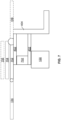
- FIGS. 1A and 1B illustrate an example hinged device test system 100 to perform mechanical property testing on a multi-hinged device 102.
- the example multi-hinged device 102 may be an electronic or other device having two or more hinges 104a, 104b allowing at least a first portion 106, a second portion 108, and a third portion 110 of the hinged device 102 to at least partially fold.
- the second portion 108 and the third portion 110 of the multi-hinged device 102 are configured to fold in a double infold arrangement, in which both portions 108, 110 fold toward a same side of the center portion 106.
- the system 100 of FIGS. 1A and 1B is configured to repeatedly fold and unfold the hinged device 102 to measure forces associated with the folding and unfolding (e.g., resistive forces, spring forces, etc.).
- the example system 100 may be controlled to fold the portion 108 while measuring the forces, and subsequently measuring the portion 110 while measuring the forces.
- FIG. 1A illustrates the multi-hinged device 102 and the folding path of the second portion 108
- FIG. 1B illustrates the multi-hinged device 102 and the folding path of the third portion 110 while the second portion 108 is already in a folded position.
- the first plate 112 has a first surface 134 to which the first portion 106 of the hinged device 102 is attached or affixed, and held stationary with respect to the first surface 134.
- the second plate 114 has a second surface 136 to which the second portion 108 of the hinged device 102 is attached or affixed, and held stationary with respect to the second surface 136.
- the third plate 116 has a third surface 138 to which the third portion 108 of the hinged device 102 is attached or affixed, and held stationary with respect to the third surface 138. Adjacent ones of the plates 112, 114, 116 are separated by respective gaps, which are bridged by the hinges 104a, 104b.
- the first drive arm(s) 122 moves the corresponding cam follower(s) 118 to cause the second plate 114 to rotate about a pivot axis of the hinge 104a of the hinged device 102.
- the actuator 126 rotates the drive arm(s) 122 to cause the second plate 114 to move the second portion 108 of the hinged device 102 from the first position (shown in solid lines) toward the first portion 106 in the folded position (shown in broken lines).
- the drive arm(s) 122 allow motion of the cam follower(s) 118 along slot(s) defined by the drive arm(s) 122 so that the system 100 limits or eliminates force on the first portion 106 of the hinged device 102 by the weight of the second plate 114 or the drive arm(s) 122, such that the measured force on the first portion 106 of the hinged device 102 is completely determined by the actuation of the hinge 104a.
- the actuator 126 may be a motor attached to the drive arm(s) 122 to rotate the drive arm(s) 122 about a pivot of the drive arm(s) 122. Additionally or alternatively, the drive arm(s) 122 may be actuated manually.
- the second drive arm(s) 124 move the corresponding cam follower(s) 120 to cause the third plate 116 to rotate about a pivot axis of the hinge 104b of the hinged device 102.
- the actuator 128 rotates the second drive arm(s) 124 to cause the third plate 116 to move the third portion 110 of the hinged device 102 from the first position (shown in solid lines) toward the first portion 106 in the folded position (shown in broken lines).
- the drive arm(s) 124 allow motion of the cam follower(s) 120 along slot(s) defined by the drive arm(s) 124 so that the system 100 limits or eliminates force on the first portion 106 of the hinged device 102 by the weight of the third plate 116 or the drive arm(s) 124, such that the measured force on the first portion 106 of the hinged device 102 is completely determined by the actuation of the hinge 104b.
- the actuator 128 may be a motor attached to the drive arm(s) 124 to rotate the drive arm(s) 124 about a pivot of the drive arm(s) 124.
- the load cell 130 measures loads on the first plate 112 while the actuator 126 moves the second plate 114 and while the actuator 128 moves the third plate 116.
- the load cell 130 measures stress (e.g., folding force) on the hinged device 102 as the hinged device 102 is folded by measuring load exerted by the first portion 106 of the hinged device 102 onto the first plate 112.
- the translation linkage 132 limits movement of the first plate 112 in directions other than the direction in which the load cell 130 is loaded by the first plate 112. For example, if the load cell 130 is configured to measure loads in a direction perpendicular to the plane of the first surface 134, the translation linkage 132 limits movement of the first plate 112 in directions parallel to the plane of the first surface 134 while permitting load to be transferred from the first plate 112 to the load cell 130.
- An example translation linkage 132 may include one or more four-bar linkages coupled to a frame that is fixed with respect to the load cell 130. In some other examples, the translation linkage 132 includes one or more flexures.
- the translation linkage 132 is further limited in a direction toward the load cell 130 to prevent overloading of the load cell 130.
- a stopping point may be attached to the frame to prevent movement of the four-bar linkage(s) and the first plate 112 toward the load cell 130 beyond the stopping point.
- the example load cell 130 may be biased or offset after securing the hinged device 102 to the first plate 112, the second plate 112, and the third plate 114 to subtract a preload from the test measurements.
- the preload on the load cell 130 may occur due to the weight of the first plate 112, the weight of translation linkage 132, and/or the weight of the first portion 106 and/or the hinges 104a, 104b of the hinged device 102 on the first plate 112.
- the load cell 130 can be calibrated or offset to measure the stress on the hinged device 102 during folding and unfolding.
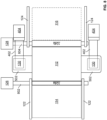
- FIGS. 2A and 2B illustrate an example hinged device test system 200 to perform mechanical property testing on a multi-hinged device 202 in which the hinges 204a, 204b fold toward opposite sides of the device 202.
- the example multi-hinged device 202 includes a first portion 206, a second portion 208 connected to the first portion 206 via a first hinge 204a, and a third portion 210 connected to the first portion via a second hinge 204b.
- the example third portion 210 is configured to fold to an opposite side of the first portion 206 than the second portion 208 (e.g., an inner-outer fold).
- the example system 200 of FIG. 2A and 2B is similar to the example system 100 of FIGS. 1A and 1B , except that the third plate 116 is configured on to connect to a different side of the third portion 210 of the device 202 to fold the third portion 210 toward an opposite side of the first portion 206 from the second portion 208.
- the load cell 130 may be configured to measure loads in a first direction when folding the second portion 208 towards the first side of the first portion 206, and measure loads in a second direction when folder the third portion 210 towards the second side of the first portion 206.
- FIG. 3 is a block diagram of an example implementation of the hinged device test systems 100, 200 of FIGS. 1A, 1B , 2A , and/or 2B.
- the hinged device test system 100 includes a test fixture 301 and a computing device 302.
- the example computing device 302 may be a general-purpose computer, a laptop computer, a tablet computer, a mobile device, a server, an all-in-one computer, and/or any other type of computing device.
- the computing device 302 of FIG. 3 includes a processor 303, which may be a general-purpose central processing unit (CPU).
- the processor 303 may include one or more specialized processing units, such as FPGA, RISC processors with an ARM core, graphic processing units, digital signal processors, and/or system-on-chips (SoC).
- the processor 303 executes machine-readable instructions 304 that may be stored locally at the processor (e.g., in an included cache or SoC), in a random access memory 306 (or other volatile memory), in a read-only memory 308 (or other non-volatile memory such as FLASH memory), and/or in a mass storage device 310.
- the example mass storage device 310 may be a hard drive, a solid-state storage drive, a hybrid drive, a RAID array, and/or any other mass data storage device.
- a bus 312 enables communications between the processor 303, the RAM 306, the ROM 308, the mass storage device 310, a network interface 314, and/or an input/output interface 316.
- An example network interface 314 includes hardware, firmware, and/or software to connect the computing device 302 to a communications network 318 such as the Internet.
- the network interface 314 may include IEEE 802.X-compliant wireless and/or wired communications hardware for transmitting and/or receiving communications.
- An example I/O interface 316 of FIG. 3 includes hardware, firmware, and/or software to connect one or more input/output devices 320 to the processor 303 for providing input to the processor 303 and/or providing output from the processor 303.
- the I/O interface 316 may include a graphics-processing unit for interfacing with a display device, a universal serial bus port for interfacing with one or more USB-compliant devices, a FireWire, a field bus, and/or any other type of interface.
- the example extensometer system 10 includes a display device 324 (e.g., an LCD screen) coupled to the I/O interface 316.
- I/O device(s) 320 may include a keyboard, a keypad, a mouse, a trackball, a pointing device, a microphone, an audio speaker, a display device, an optical media drive, a multi-touch touch screen, a gesture recognition interface, a magnetic media drive, and/or any other type of input and/or output device.
- the computing device 302 may access a non-transitory machine-readable medium 322 via the I/O interface 316 and/or the I/O device(s) 320.
- machine-readable medium 322 of FIG. 8 include optical discs (e.g., compact discs (CDs), digital versatile/video discs (DVDs), Blu-ray discs, etc.), magnetic media (e.g., floppy disks), portable storage media (e.g., portable flash drives, secure digital (SD) cards, etc.), and/or any other type of removable and/or installed machine-readable media.
- the test fixture 301 is coupled to the computing device 302.
- the test fixture 301 is coupled to the computing device via the I/O interface 316, such as via a USB port, a Thunderbolt port, a FireWire (IEEE 1394) port, and/or any other type serial or parallel data port.
- the test fixture 301 is coupled to the network interface 314 and/or to the I/O interface 316 via a wired or wireless connection (e.g., Ethernet, Wi-Fi, etc.), either directly or via the network 318.
- the test fixture 301 includes a frame 328, a load cell 330, material fixtures 336, and a control processor 338.
- the frame 328 provides rigid structural support for the other components of the test fixture 301 that perform the test.
- the load cell 330 may implement the load cell 130 of FIGS. 1A, 1B , 2A , and/or 2B, and measures force applied to a material under test (e.g., the hinged device 102) by an actuator 346 via grips 348 (e.g., the plates 112, 114, 116).
- the actuator 346 applies force to the material under test and/or forces displacement of the material under test, while the grips 348 grasp or otherwise couple the material under test to the actuator 346.
- Example actuators that may be used to provide force and/or motion of a component of the test fixture 301 include electric motors, pneumatic actuators, hydraulic actuators, piezoelectric actuators, relays, and/or switches. While the example test fixture 301 uses a motor, such as a servo or direct-drive linear motor, other systems may use different types of actuators. For example, hydraulic actuators, pneumatic actuators, and/or any other type of actuator may be used based on the requirements of the system.
- the example grips 336 include platens, clamps, and/or other types of fixtures, depending on the mechanical property being tested and/or the material under test.
- the grips 336 may be manually configured, controlled via manual input, and/or automatically controlled by the control processor 338.
- the test system 100 may further include one or more control panels 350, including one or more input devices 352.
- the input devices 352 may include buttons, switches, and/or other input devices located on an operator control panel.
- the input devices 352 may include buttons that control the actuator 342 to jog (e.g., position) the grips 348 to a desired position, switches (e.g., foot switches) that control the grips 348 to close or open (e.g., via another actuator), and/or any other input devices to control operation of the testing test fixture 301.
- the example control processor 338 communicates with the computing device 302 to, for example, receive test parameters from the computing device 302 and/or report measurements and/or other results to the computing device 302.
- the control processor 338 may include one or more communication or I/O interfaces to enable communication with the computing device 302.
- the control processor 338 may control the actuator 346 to move in a given direction and/or to control the speed of the actuator 346, control the fixture(s) 336 to grasp or release a material under test, and/or receive measurements from the displacement transducer 332, the load cell 330 and/or other transducers.
- the example control processor 338 is configured to implement a repetitive motion testing process in which a test specimen (e.g., the hinged device 102) is subjected to testing in the test fixture 301. For example, to measure stress on the hinged device 102 during or after a series of folding and unfolding motions, the control processor 338 controls the actuator 346 to move the grips 348 (e.g., the first, second, and third plates 112, 114, 116) while monitoring the load cell 330 to measure stress on the hinged device 102. In some examples, the control processor 338 monitors a motor encoder of the actuator 346 to determine a folding angle and/or establish a folding degree-per-pulse ratio.
- a test specimen e.g., the hinged device 102
- the control processor 338 controls the actuator 346 to move the grips 348 (e.g., the first, second, and third plates 112, 114, 116) while monitoring the load cell 330 to measure stress on the hinged device 102.
- FIG. 4 is a perspective view of an example implementation of the hinged device test system 100 of FIGS. 1A and 1B configured to perform load measurement testing on a multi-hinged device in which the hinges fold toward a same side of the device.
- the translation linkage 132 includes multiple flexures 402 attached to brackets 404, which support the flexures 402 at the desired height.
- the example system 100 is illustrated in FIG. 4 without the multi-hinge device 102.
- FIG. 5 is a perspective view of an example implementation of the hinged device test system 200 of FIGS. 2A and 2B configured to perform load measurement testing on a multi-hinged device 202 in which the hinges fold toward opposite sides of the device.
- the translation linkage 132 e.g., flexures 402 and brackets 404
- the load cell(s) 130 are positioned to the sides of the first plate 112, such that the translation linkage 132 and the load cell(s) 130 do not interfere with the path of motion of the second plate 116.
- the first plate 112 may include extensions 502 to couple the first plate to the flexures 402 and/or the load cell(s) 130.
- the example of FIG. 5 may implement either of the example test systems 100, 200 of FIGS. 1A, 1B , 2A, and 2B by changing the position of the pivot point of the pivot the drive arm 124 via another bracket 504.
- the drive arm 124 is configured to test inner-outer folding devices (e.g., the system 200).
- the drive arm 124 is configured to test double infold devices (e.g., the system 100). While multiple actuators 128 and corresponding shafts are illustrated as driving the third plate 116 in the example of FIG. 5 , only one of the illustrated actuators 128 would be used in a given configuration.
- drive arms 510 may be coupled to the actuator 128 to rotate the third plate 116 via a cam follower 512 attached to the third plate 116.
- the drive arms 510 are offset (e.g., L-shaped) to align the axis of rotation of the third plate 116 with the device under test.
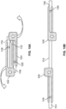
- FIGS. 6A-6C illustrate side views of different orientations of an example drive arm 602 that may be used to implement the drive arms 122, 124 of FIGS. 1A-2B , 4 , and/or 5 , and corresponding orientations of the second or third plates 114, 116 attached to a cam follower 118, 120.
- the example drive arm 602 has a drive arm pivot axis 604, while the plate 114, 116 has a plate pivot axis 606 that is controlled by the hinge pivot axis of the multi-hinged device 102, 202.
- FIG. 7 is a block diagram illustrating an example arrangement of plates, support flexures, and load cells that may be used to implement the hinged device test systems 100, 200 of FIGS. 1A-2B , 4 , and/or 5 .
- FIG. 8 is a top view of an example arrangement of the hinged device test system of FIGS. 1A-2B , 4 , and/or 5 .
- the center plate 112 may be supported on both sides by flexures 402 and flexure mounting brackets 404, which are coupled to the extensions 502 (e.g., tabs) of the center plate 112 so as to locate the flexures 402 out of the folding paths of the folding plates 114, 116.
- the example of FIG. 8 includes load cells 130 on each side of the center plate 112 to accurately measure the forces on the center plate 112 during folding.
- the example actuators 126, 128 may be coupled to pivot the drive arms 122, 124 on either side of the plates 114, 116 via respective shafts 802, 804.
- FIGS. 9A and 9B illustrate an example folding arrangement of drive arms 122, 124 for the hinged device test system 100 of FIGS. 1A-2B , 4 , and/or 5 for a multi-hinged device configured for a double infold.
- FIGS. 10A and 10B illustrate an example folding arrangement of drive arms 122, 124 for the hinged device test system 200 of FIGS. 1A-2B , 4 , and/or 5 for a multi-hinged device configured for an inner-outer fold.
- the present methods and systems may be realized in hardware, software, and/or a combination of hardware and software.
- the present methods and/or systems may be realized in a centralized fashion in at least one computing system, or in a distributed fashion where different elements are spread across several interconnected computing systems. Any kind of computing system or other apparatus adapted for carrying out the methods described herein is suited.
- a typical combination of hardware and software may include a general-purpose computing system with a program or other code that, when being loaded and executed, controls the computing system such that it carries out the methods described herein.
- Another typical implementation may comprise an application specific integrated circuit or chip.
- Some implementations may comprise a non-transitory machine-readable (e.g., computer readable) medium (e.g., FLASH drive, optical disk, magnetic storage disk, or the like) having stored thereon one or more lines of code executable by a machine, thereby causing the machine to perform processes as described herein.
- a non-transitory machine-readable medium e.g., FLASH drive, optical disk, magnetic storage disk, or the like
- non-transitory machine-readable medium is defined to include all types of machine readable storage media and to exclude propagating signals.
- circuits and circuitry refer to physical electronic components (i.e. hardware) and any software and/or firmware ("code") which may configure the hardware, be executed by the hardware, and or otherwise be associated with the hardware.
- code software and/or firmware
- a particular processor and memory may comprise a first "circuit” when executing a first one or more lines of code and may comprise a second "circuit” when executing a second one or more lines of code.
- and/or means any one or more of the items in the list joined by “and/or”.
- x and/or y means any element of the three-element set ⁇ (x), (y), (x, y) ⁇ .
- x and/or y means “one or both of x and y”.
- x, y, and/or z means any element of the seven-element set ⁇ (x), (y), (z), (x, y), (x, z), (y, z), (x, y, z) ⁇ .
- x, y and/or z means “one or more of x, y and z”.
- exemplary means serving as a non-limiting example, instance, or illustration.
- the terms "e.g.,” and “for example” set off lists of one or more non-limiting examples, instances, or illustrations.
- circuitry is "operable" to perform a function whenever the circuitry comprises the necessary hardware and code (if any is necessary) to perform the function, regardless of whether performance of the function is disabled or not enabled (e.g., by a user-configurable setting, factory trim, etc.).
Landscapes
- Physics & Mathematics (AREA)
- General Physics & Mathematics (AREA)
- Chemical & Material Sciences (AREA)
- Analytical Chemistry (AREA)
- Health & Medical Sciences (AREA)
- Life Sciences & Earth Sciences (AREA)
- Biochemistry (AREA)
- General Health & Medical Sciences (AREA)
- Immunology (AREA)
- Pathology (AREA)
- Investigating Strength Of Materials By Application Of Mechanical Stress (AREA)
- Testing Of Devices, Machine Parts, Or Other Structures Thereof (AREA)
Claims (15)
- Prüfsystem für eine klappbare Vorrichtung (100), aufweisend:eine erste Platte (112), die eine erste Fläche (134) aufweist, die so ausgebildet ist, dass sie einen ersten Abschnitt (106) einer zu prüfenden klappbaren Vorrichtung (102) ortsfest hält;eine zweite Platte (114), die eine zweite Fläche (136) aufweist, die so ausgebildet ist, dass sie einen zweiten Abschnitt (108) der zu prüfenden klappbaren Vorrichtung hält, wobei der zweite Abschnitt der klappbaren Vorrichtung mit dem ersten Abschnitt über ein erstes Gelenk (104a) gekoppelt ist, das einen ersten Klappradius aufweist;eine dritte Platte (116), die eine dritte Fläche (138) aufweist, die so ausgebildet ist, dass sie einen dritten Abschnitt (110) der zu prüfenden klappbaren Vorrichtung hält, wobei der dritte Abschnitt der klappbaren Vorrichtung mit dem ersten Abschnitt über ein zweites Gelenk (104b) gekoppelt ist, das einen zweiten Klappradius aufweist;einen ersten Nockenstößel (118), der mit der zweiten Platte gekoppelt ist;einen ersten Antriebsarm (122), der so ausgebildet ist, dass er den ersten Nockenstößel bewegt, um die zweite Platte zu veranlassen, sich um eine erste Gelenkdrehachse des ersten Gelenks zu drehen;einen ersten Aktor (126), der so ausgebildet ist, dass er den ersten Antriebsarm dreht;einen zweiten Nockenstößel (120), der mit der dritten Platte gekoppelt ist;einen zweiten Antriebsarm (124), der so ausgebildet ist, dass er den zweiten Nockenstößel bewegt, um die dritte Platte zu veranlassen, sich um eine zweite Gelenkdrehachse des zweiten Gelenks zu drehen;einen zweiten Aktor (128), der so ausgebildet ist, dass er den zweiten Antriebsarm dreht; undeine Wägezelle (130), die so ausgebildet ist, dass sie erste Lasten auf der ersten Platte misst, während der erste Aktor die zweite Platte bewegt, und zweite Lasten auf der ersten Platte misst, während der zweite Aktor die dritte Platte bewegt.
- Prüfsystem für eine klappbare Vorrichtung (100) nach Anspruch 1, wobei der erste Nockenstößel (118), der erste Antriebsarm (122) und der erste Aktor (126) so ausgebildet sind, dass sie den zweiten Abschnitt (108) der klappbaren Vorrichtung (102) in Richtung einer ersten Seite des ersten Abschnitts (106) der klappbaren Vorrichtung klappen, und der zweite Nockenstößel (120), der zweite Antriebsarm (124) und der zweite Aktor (128) so ausgebildet sind, dass sie den dritten Abschnitt (110) der klappbaren Vorrichtung in Richtung der ersten Seite des ersten Abschnitts der klappbaren Vorrichtung klappen, wobei der zweite Klappradius größer als der erste Klappradius ist.
- Prüfsystem für eine klappbare Vorrichtung (100) nach Anspruch 2, ferner aufweisend ein Biegeelement (402), das so ausgebildet ist, dass es die erste Platte (112) trägt, um eine Bewegung der ersten Platte in Richtungen zu begrenzen, die von einer Richtung verschieden sind, in der die Wägezelle (130) so ausgebildet ist, dass sie Lasten misst, und eine Übertragung der Last von der zu prüfenden klappbaren Vorrichtung (102) auf die Wägezelle ermöglicht.
- Prüfsystem für eine klappbare Vorrichtung (100) nach Anspruch 1, wobei die Wägezelle (130) eine aus einer Vielzahl von Wägezellen ist, die mit der ersten Platte (112) gekoppelt ist, um die ersten Lasten und die zweiten Lasten zu messen.
- Prüfsystem für eine klappbare Vorrichtung (100) nach Anspruch 1, wobei der erste Aktor (126) so ausgebildet ist, dass er den ersten Antriebsarm (122) während eines ersten Zeitraums dreht, während die Wägezelle (130) die ersten Lasten misst, und der zweite Aktor (128) so ausgebildet ist, dass er den zweiten Antriebsarm (124) während eines zweiten Zeitraums dreht, während die Wägezelle die zweiten Lasten misst, wobei sich der erste Zeitraum nicht mit dem zweiten Zeitraum überschneidet.
- Prüfsystem für eine klappbare Vorrichtung (100) nach Anspruch 1, wobei der erste Antriebsarm (122) einen ersten Schlitz aufweist, der sich radial von einer ersten Armdrehachse des ersten Antriebsarms erstreckt, und der erste Schlitz so ausgebildet ist, dass er den ersten Nockenstößel (118) führt, wenn der erste Antriebsarm gedreht wird.
- Prüfsystem für eine klappbare Vorrichtung (100) nach Anspruch 1, wobei der zweite Antriebsarm (124) einen zweiten Schlitz aufweist, wobei eine zweite Armdrehachse des zweiten Antriebsarms von einer Linie versetzt ist, die sich durch den zweiten Schlitz erstreckt, wobei der zweite Schlitz optional so ausgebildet ist, dass der zweite Nockenstößel (120) sich frei entlang des zweiten Schlitzes bewegen kann, wenn der zweite Antriebsarm gedreht wird.
- Prüfsystem für eine klappbare Vorrichtung (100) nach Anspruch 1, wobei der erste Nockenstößel (118), der ersten Antriebsarm (122) und der erste Aktor (126) so ausgebildet sind, dass sie den zweiten Abschnitt (108) der klappbaren Vorrichtung (102) in Richtung einer ersten Seite des ersten Abschnitts (106) der klappbaren Vorrichtung klappen, und der zweite Nockenstößel (120), der zweite Antriebsarm (124) und der zweite Aktor (128) so ausgebildet sind, dass sie den dritten Abschnitt (110) der klappbaren Vorrichtung in Richtung der zweiten Seite des ersten Abschnitts der klappbaren Vorrichtung klappen.
- Prüfsystem für eine klappbare Vorrichtung (100) nach Anspruch 8, ferner aufweisend ein Biegeelement (402), das so ausgebildet ist, dass es die erste Platte (112) trägt, um eine Bewegung der ersten Platte in Richtungen zu begrenzen, die von einer Richtung verschieden sind, in der die Wägezelle (130) so ausgebildet ist, dass sie Lasten misst, und eine Übertragung der Last von der zu prüfenden klappbaren Vorrichtung (102) auf die Wägezelle ermöglicht, wobei das Biegeelement in Bezug auf die Bewegungsbahnen des ersten (122) und des zweiten Antriebsarms (124) seitlich zur ersten Platte angeordnet ist.
- Prüfsystem für eine klappbare Vorrichtung (100) nach Anspruch 1, ferner aufweisend:eine Welle (804), die so ausgebildet ist, dass sie den zweiten Aktor (128) mit dem zweiten Antriebsarm (124) koppelt; undeine Halterung (404), die so ausgebildet ist, dass sie die Welle in einer ersten Position hält, um den dritten Abschnitt (110) der klappbaren Vorrichtung (102) in Richtung einer zweiten Seite des ersten Abschnitts (106) der klappbaren Vorrichtung zu klappen, und um die Welle in einer zweiten Position zu halten, um den dritten Abschnitt der klappbaren Vorrichtung in Richtung einer ersten Seite des ersten Abschnitts der klappbaren Vorrichtung zu klappen, wobei der erste Nockenstößel (118), der erste Antriebsarm (122) und der erste Aktor (126) so ausgebildet sind, dass sie den zweiten Abschnitt (108) der klappbaren Vorrichtung in Richtung der ersten Seite des ersten Abschnitts der klappbaren Vorrichtung klappen.
- Prüfsystem für eine klappbare Vorrichtung (100) nach Anspruch 10, wobei die erste Position der Welle (804) in der Halterung (404) auf der ersten Seite des ersten Abschnitts (106) angeordnet ist und die zweite Position der Welle in der Halterung auf der zweiten Seite des ersten Abschnitts angeordnet ist.
- Prüfsystem für eine klappbare Vorrichtung (100) nach Anspruch 1, ferner aufweisend eine erste Gelenkhalteplatte, die so ausgebildet ist, dass sie eine erste Seite des ersten Gelenks (104a) getrennt von der ersten Platte (112) hält.
- Prüfsystem für eine klappbare Vorrichtung (100) nach Anspruch 12, wobei die zweite Platte (114) so ausgebildet ist, dass sie die zweite Seite des ersten Gelenks (104a) hält, sodass das erste Gelenk einen Klappweg des zweiten Abschnitts (108) der zu prüfenden klappbaren Vorrichtung (102) steuert, wenn der erste Aktor (126) die zweite Platte bewegt.
- Prüfsystem für eine klappbare Vorrichtung (100) nach Anspruch 12, wobei die Gelenkhalteplatte, die zweite Platte (114), die erste Platte (112), der erste Antriebsarm (122) und der erste Nockenstößel (118) so ausgebildet sind, dass sie Kräfte auf die Wägezelle (130) auf Kräfte der zu prüfenden klappbaren Vorrichtung (102) während des Ein- und Ausklappens begrenzen, ohne dass Kräfte durch das erste Gelenk (104a) während des Ein- und Ausklappens erzeugt werden.
- Prüfsystem für eine klappbare Vorrichtung (100) nach Anspruch 1, wobei der erste Aktor (126) so ausgebildet ist, dass er den ersten Antriebsarm (122) dreht, und der zweite Aktor (128) so ausgebildet ist, dass er den zweiten Antriebsarm (124) gleichzeitig dreht, während die Wägezelle (130) die Lasten misst.
Applications Claiming Priority (3)
| Application Number | Priority Date | Filing Date | Title |
|---|---|---|---|
| US202163185165P | 2021-05-06 | 2021-05-06 | |
| US17/737,386 US12078575B2 (en) | 2021-05-06 | 2022-05-05 | Methods and apparatus to perform load measurements on multi-hinged devices |
| PCT/US2022/028025 WO2022236019A1 (en) | 2021-05-06 | 2022-05-06 | Methods and apparatus to perform load measurements on multi-hinged devices |
Publications (2)
| Publication Number | Publication Date |
|---|---|
| EP4334697A1 EP4334697A1 (de) | 2024-03-13 |
| EP4334697B1 true EP4334697B1 (de) | 2024-12-25 |
Family
ID=83901384
Family Applications (1)
| Application Number | Title | Priority Date | Filing Date |
|---|---|---|---|
| EP22725651.8A Active EP4334697B1 (de) | 2021-05-06 | 2022-05-06 | Verfahren und vorrichtung zur durchführung von lastmessungen an vorrichtungen mit mehreren scharnieren |
Country Status (8)
| Country | Link |
|---|---|
| US (2) | US12078575B2 (de) |
| EP (1) | EP4334697B1 (de) |
| JP (1) | JP2024518391A (de) |
| KR (1) | KR20240006601A (de) |
| CN (1) | CN117480369A (de) |
| ES (1) | ES3015518T3 (de) |
| PL (1) | PL4334697T3 (de) |
| TW (1) | TW202248622A (de) |
Families Citing this family (9)
| Publication number | Priority date | Publication date | Assignee | Title |
|---|---|---|---|---|
| US11885773B2 (en) * | 2019-06-24 | 2024-01-30 | Illinois Tool Works Inc. | Methods and apparatus to perform load measurements on flexible substrates |
| US20240011752A1 (en) * | 2022-07-07 | 2024-01-11 | Illinois Tool Works Inc. | Systems and methods to measure specimen dimensions |
| KR20240045689A (ko) * | 2022-09-30 | 2024-04-08 | 현대자동차주식회사 | 차량용 시트 안티 핀치 검증 장치 및 그 방법 |
| CN115808349B (zh) * | 2022-12-12 | 2023-06-09 | 太原科技大学 | 一种金属极薄带疲劳弯曲折叠试验装置 |
| KR102715048B1 (ko) * | 2023-09-25 | 2024-10-11 | 주식회사 브릴스 | 실시간 모니터링이 가능한 시트 벨트 알림 검사 장치 |
| KR102766570B1 (ko) * | 2023-12-18 | 2025-02-12 | (주)플렉시고 | 스트레스프리를 위한 폴딩 메카니즘 |
| KR102744161B1 (ko) * | 2024-10-18 | 2024-12-19 | 주식회사 브릴스 | 시트 폴딩 작동력 검사 시스템 |
| KR102744155B1 (ko) * | 2024-10-29 | 2024-12-19 | 주식회사 브릴스 | 전장 품질 검사 시스템 |
| KR102744154B1 (ko) * | 2024-10-29 | 2024-12-19 | 주식회사 브릴스 | 다차종 대응이 가능한 시트 검사 시스템 |
Family Cites Families (14)
| Publication number | Priority date | Publication date | Assignee | Title |
|---|---|---|---|---|
| MY110404A (en) | 1993-03-23 | 1998-04-30 | Amcor Ltd | Force testing machine |
| TWI377343B (en) | 2008-11-11 | 2012-11-21 | Ind Tech Res Inst | Clip for detecting bending forces and electrical characteristics |
| US8787016B2 (en) | 2011-07-06 | 2014-07-22 | Apple Inc. | Flexible display devices |
| US8544340B1 (en) | 2011-09-26 | 2013-10-01 | The United States Of America As Represented By The Secretary Of The Air Force | Device for testing thin specimens in pure bending |
| CN202522405U (zh) | 2012-04-10 | 2012-11-07 | 厦门宇龙机械有限公司 | 一种汽车侧门铰链的耐久性试验装置 |
| KR101489667B1 (ko) | 2013-11-26 | 2015-02-04 | 주식회사 이노테크 | 플렉시블 디스플레이의 벤딩 시험장치 |
| CN106896463B (zh) | 2015-12-17 | 2020-07-31 | 宁波舜宇车载光学技术有限公司 | 用于车载光学成像系统的光学镜头 |
| CN106338389A (zh) | 2016-08-30 | 2017-01-18 | 丰业迪睦斯(芜湖)汽车部件有限公司 | 门铰链疲劳强度测试装置 |
| KR101843874B1 (ko) | 2017-01-09 | 2018-03-30 | (주)플렉시고 | 플렉시블소재 내구성 평가용 폴딩장치 |
| JP6912790B2 (ja) | 2017-08-24 | 2021-08-04 | ユアサシステム機器株式会社 | 変形試験器 |
| CN107631861A (zh) | 2017-08-28 | 2018-01-26 | 武汉华星光电半导体显示技术有限公司 | 柔性显示装置弯折测试设备及系统 |
| US11885773B2 (en) | 2019-06-24 | 2024-01-30 | Illinois Tool Works Inc. | Methods and apparatus to perform load measurements on flexible substrates |
| US12000803B2 (en) | 2019-06-24 | 2024-06-04 | Illinois Tool Works Inc. | Methods and apparatus to perform load measurements on flexible substrates |
| US11761867B2 (en) | 2020-04-30 | 2023-09-19 | Illinois Tool Works Inc. | Methods and apparatus to perform load measurements on hinged devices |
-
2022
- 2022-05-05 US US17/737,386 patent/US12078575B2/en active Active
- 2022-05-06 CN CN202280041798.7A patent/CN117480369A/zh active Pending
- 2022-05-06 JP JP2023568075A patent/JP2024518391A/ja active Pending
- 2022-05-06 EP EP22725651.8A patent/EP4334697B1/de active Active
- 2022-05-06 KR KR1020237041968A patent/KR20240006601A/ko active Pending
- 2022-05-06 ES ES22725651T patent/ES3015518T3/es active Active
- 2022-05-06 TW TW111117163A patent/TW202248622A/zh unknown
- 2022-05-06 PL PL22725651.8T patent/PL4334697T3/pl unknown
-
2024
- 2024-09-03 US US18/823,455 patent/US20250020548A1/en active Pending
Also Published As
| Publication number | Publication date |
|---|---|
| TW202248622A (zh) | 2022-12-16 |
| US20250020548A1 (en) | 2025-01-16 |
| US12078575B2 (en) | 2024-09-03 |
| KR20240006601A (ko) | 2024-01-15 |
| US20220357255A1 (en) | 2022-11-10 |
| JP2024518391A (ja) | 2024-05-01 |
| EP4334697A1 (de) | 2024-03-13 |
| CN117480369A (zh) | 2024-01-30 |
| PL4334697T3 (pl) | 2025-04-28 |
| ES3015518T3 (en) | 2025-05-06 |
Similar Documents
| Publication | Publication Date | Title |
|---|---|---|
| EP4334697B1 (de) | Verfahren und vorrichtung zur durchführung von lastmessungen an vorrichtungen mit mehreren scharnieren | |
| US12203903B2 (en) | Methods and apparatus to perform load measurements on hinged devices | |
| US20250137895A1 (en) | Methods and apparatus to perform load measurements on flexible substrates | |
| US20240248020A1 (en) | Methods and apparatus to perform load measurements on flexible substrates | |
| WO2022236019A1 (en) | Methods and apparatus to perform load measurements on multi-hinged devices | |
| EP4627316A1 (de) | Probeneinführungs- und -ausrichtungsvorrichtungen und materialtestsysteme mit probeneinführungs- und -ausrichtungsvorrichtungen |
Legal Events
| Date | Code | Title | Description |
|---|---|---|---|
| STAA | Information on the status of an ep patent application or granted ep patent |
Free format text: STATUS: UNKNOWN |
|
| STAA | Information on the status of an ep patent application or granted ep patent |
Free format text: STATUS: THE INTERNATIONAL PUBLICATION HAS BEEN MADE |
|
| PUAI | Public reference made under article 153(3) epc to a published international application that has entered the european phase |
Free format text: ORIGINAL CODE: 0009012 |
|
| STAA | Information on the status of an ep patent application or granted ep patent |
Free format text: STATUS: REQUEST FOR EXAMINATION WAS MADE |
|
| 17P | Request for examination filed |
Effective date: 20231102 |
|
| AK | Designated contracting states |
Kind code of ref document: A1 Designated state(s): AL AT BE BG CH CY CZ DE DK EE ES FI FR GB GR HR HU IE IS IT LI LT LU LV MC MK MT NL NO PL PT RO RS SE SI SK SM TR |
|
| DAV | Request for validation of the european patent (deleted) | ||
| DAX | Request for extension of the european patent (deleted) | ||
| GRAP | Despatch of communication of intention to grant a patent |
Free format text: ORIGINAL CODE: EPIDOSNIGR1 |
|
| STAA | Information on the status of an ep patent application or granted ep patent |
Free format text: STATUS: GRANT OF PATENT IS INTENDED |
|
| INTG | Intention to grant announced |
Effective date: 20240816 |
|
| GRAS | Grant fee paid |
Free format text: ORIGINAL CODE: EPIDOSNIGR3 |
|
| P01 | Opt-out of the competence of the unified patent court (upc) registered |
Free format text: CASE NUMBER: APP_55990/2024 Effective date: 20241011 |
|
| GRAA | (expected) grant |
Free format text: ORIGINAL CODE: 0009210 |
|
| STAA | Information on the status of an ep patent application or granted ep patent |
Free format text: STATUS: THE PATENT HAS BEEN GRANTED |
|
| AK | Designated contracting states |
Kind code of ref document: B1 Designated state(s): AL AT BE BG CH CY CZ DE DK EE ES FI FR GB GR HR HU IE IS IT LI LT LU LV MC MK MT NL NO PL PT RO RS SE SI SK SM TR |
|
| REG | Reference to a national code |
Ref country code: GB Ref legal event code: FG4D |
|
| REG | Reference to a national code |
Ref country code: CH Ref legal event code: EP |
|
| REG | Reference to a national code |
Ref country code: DE Ref legal event code: R096 Ref document number: 602022009149 Country of ref document: DE |
|
| REG | Reference to a national code |
Ref country code: IE Ref legal event code: FG4D |
|
| REG | Reference to a national code |
Ref country code: LT Ref legal event code: MG9D |
|
| PG25 | Lapsed in a contracting state [announced via postgrant information from national office to epo] |
Ref country code: HR Free format text: LAPSE BECAUSE OF FAILURE TO SUBMIT A TRANSLATION OF THE DESCRIPTION OR TO PAY THE FEE WITHIN THE PRESCRIBED TIME-LIMIT Effective date: 20241225 |
|
| PG25 | Lapsed in a contracting state [announced via postgrant information from national office to epo] |
Ref country code: FI Free format text: LAPSE BECAUSE OF FAILURE TO SUBMIT A TRANSLATION OF THE DESCRIPTION OR TO PAY THE FEE WITHIN THE PRESCRIBED TIME-LIMIT Effective date: 20241225 |
|
| PG25 | Lapsed in a contracting state [announced via postgrant information from national office to epo] |
Ref country code: BG Free format text: LAPSE BECAUSE OF FAILURE TO SUBMIT A TRANSLATION OF THE DESCRIPTION OR TO PAY THE FEE WITHIN THE PRESCRIBED TIME-LIMIT Effective date: 20241225 |
|
| PG25 | Lapsed in a contracting state [announced via postgrant information from national office to epo] |
Ref country code: NO Free format text: LAPSE BECAUSE OF FAILURE TO SUBMIT A TRANSLATION OF THE DESCRIPTION OR TO PAY THE FEE WITHIN THE PRESCRIBED TIME-LIMIT Effective date: 20250325 |
|
| PG25 | Lapsed in a contracting state [announced via postgrant information from national office to epo] |
Ref country code: GR Free format text: LAPSE BECAUSE OF FAILURE TO SUBMIT A TRANSLATION OF THE DESCRIPTION OR TO PAY THE FEE WITHIN THE PRESCRIBED TIME-LIMIT Effective date: 20250326 Ref country code: LV Free format text: LAPSE BECAUSE OF FAILURE TO SUBMIT A TRANSLATION OF THE DESCRIPTION OR TO PAY THE FEE WITHIN THE PRESCRIBED TIME-LIMIT Effective date: 20241225 |
|
| PG25 | Lapsed in a contracting state [announced via postgrant information from national office to epo] |
Ref country code: RS Free format text: LAPSE BECAUSE OF FAILURE TO SUBMIT A TRANSLATION OF THE DESCRIPTION OR TO PAY THE FEE WITHIN THE PRESCRIBED TIME-LIMIT Effective date: 20250325 |
|
| REG | Reference to a national code |
Ref country code: NL Ref legal event code: MP Effective date: 20241225 |
|
| REG | Reference to a national code |
Ref country code: ES Ref legal event code: FG2A Ref document number: 3015518 Country of ref document: ES Kind code of ref document: T3 Effective date: 20250506 |
|
| PG25 | Lapsed in a contracting state [announced via postgrant information from national office to epo] |
Ref country code: NL Free format text: LAPSE BECAUSE OF FAILURE TO SUBMIT A TRANSLATION OF THE DESCRIPTION OR TO PAY THE FEE WITHIN THE PRESCRIBED TIME-LIMIT Effective date: 20241225 |
|
| REG | Reference to a national code |
Ref country code: AT Ref legal event code: MK05 Ref document number: 1754535 Country of ref document: AT Kind code of ref document: T Effective date: 20241225 |
|
| PG25 | Lapsed in a contracting state [announced via postgrant information from national office to epo] |
Ref country code: SM Free format text: LAPSE BECAUSE OF FAILURE TO SUBMIT A TRANSLATION OF THE DESCRIPTION OR TO PAY THE FEE WITHIN THE PRESCRIBED TIME-LIMIT Effective date: 20241225 |
|
| PGFP | Annual fee paid to national office [announced via postgrant information from national office to epo] |
Ref country code: DE Payment date: 20250529 Year of fee payment: 4 Ref country code: PL Payment date: 20250506 Year of fee payment: 4 |
|
| PGFP | Annual fee paid to national office [announced via postgrant information from national office to epo] |
Ref country code: ES Payment date: 20250602 Year of fee payment: 4 |
|
| PG25 | Lapsed in a contracting state [announced via postgrant information from national office to epo] |
Ref country code: IS Free format text: LAPSE BECAUSE OF FAILURE TO SUBMIT A TRANSLATION OF THE DESCRIPTION OR TO PAY THE FEE WITHIN THE PRESCRIBED TIME-LIMIT Effective date: 20250425 |
|
| PGFP | Annual fee paid to national office [announced via postgrant information from national office to epo] |
Ref country code: IT Payment date: 20250531 Year of fee payment: 4 |
|
| PG25 | Lapsed in a contracting state [announced via postgrant information from national office to epo] |
Ref country code: PT Free format text: LAPSE BECAUSE OF FAILURE TO SUBMIT A TRANSLATION OF THE DESCRIPTION OR TO PAY THE FEE WITHIN THE PRESCRIBED TIME-LIMIT Effective date: 20250428 |
|
| PG25 | Lapsed in a contracting state [announced via postgrant information from national office to epo] |
Ref country code: EE Free format text: LAPSE BECAUSE OF FAILURE TO SUBMIT A TRANSLATION OF THE DESCRIPTION OR TO PAY THE FEE WITHIN THE PRESCRIBED TIME-LIMIT Effective date: 20241225 |
|
| PGFP | Annual fee paid to national office [announced via postgrant information from national office to epo] |
Ref country code: FR Payment date: 20250526 Year of fee payment: 4 |
|
| PG25 | Lapsed in a contracting state [announced via postgrant information from national office to epo] |
Ref country code: RO Free format text: LAPSE BECAUSE OF FAILURE TO SUBMIT A TRANSLATION OF THE DESCRIPTION OR TO PAY THE FEE WITHIN THE PRESCRIBED TIME-LIMIT Effective date: 20241225 Ref country code: AT Free format text: LAPSE BECAUSE OF FAILURE TO SUBMIT A TRANSLATION OF THE DESCRIPTION OR TO PAY THE FEE WITHIN THE PRESCRIBED TIME-LIMIT Effective date: 20241225 |
|
| PG25 | Lapsed in a contracting state [announced via postgrant information from national office to epo] |
Ref country code: SK Free format text: LAPSE BECAUSE OF FAILURE TO SUBMIT A TRANSLATION OF THE DESCRIPTION OR TO PAY THE FEE WITHIN THE PRESCRIBED TIME-LIMIT Effective date: 20241225 |
|
| PG25 | Lapsed in a contracting state [announced via postgrant information from national office to epo] |
Ref country code: CZ Free format text: LAPSE BECAUSE OF FAILURE TO SUBMIT A TRANSLATION OF THE DESCRIPTION OR TO PAY THE FEE WITHIN THE PRESCRIBED TIME-LIMIT Effective date: 20241225 |
|
| PG25 | Lapsed in a contracting state [announced via postgrant information from national office to epo] |
Ref country code: SE Free format text: LAPSE BECAUSE OF FAILURE TO SUBMIT A TRANSLATION OF THE DESCRIPTION OR TO PAY THE FEE WITHIN THE PRESCRIBED TIME-LIMIT Effective date: 20241225 |
|
| REG | Reference to a national code |
Ref country code: DE Ref legal event code: R097 Ref document number: 602022009149 Country of ref document: DE |
|
| PG25 | Lapsed in a contracting state [announced via postgrant information from national office to epo] |
Ref country code: DK Free format text: LAPSE BECAUSE OF FAILURE TO SUBMIT A TRANSLATION OF THE DESCRIPTION OR TO PAY THE FEE WITHIN THE PRESCRIBED TIME-LIMIT Effective date: 20241225 |
|
| PLBE | No opposition filed within time limit |
Free format text: ORIGINAL CODE: 0009261 |
|
| STAA | Information on the status of an ep patent application or granted ep patent |
Free format text: STATUS: NO OPPOSITION FILED WITHIN TIME LIMIT |
|
| REG | Reference to a national code |
Ref country code: CH Ref legal event code: L10 Free format text: ST27 STATUS EVENT CODE: U-0-0-L10-L00 (AS PROVIDED BY THE NATIONAL OFFICE) Effective date: 20251105 |
|
| 26N | No opposition filed |
Effective date: 20250926 |
|
| REG | Reference to a national code |
Ref country code: CH Ref legal event code: H13 Free format text: ST27 STATUS EVENT CODE: U-0-0-H10-H13 (AS PROVIDED BY THE NATIONAL OFFICE) Effective date: 20251223 |
|
| PG25 | Lapsed in a contracting state [announced via postgrant information from national office to epo] |
Ref country code: LU Free format text: LAPSE BECAUSE OF NON-PAYMENT OF DUE FEES Effective date: 20250506 |
|
| PG25 | Lapsed in a contracting state [announced via postgrant information from national office to epo] |
Ref country code: CH Free format text: LAPSE BECAUSE OF NON-PAYMENT OF DUE FEES Effective date: 20250531 |
|
| PG25 | Lapsed in a contracting state [announced via postgrant information from national office to epo] |
Ref country code: MC Free format text: LAPSE BECAUSE OF FAILURE TO SUBMIT A TRANSLATION OF THE DESCRIPTION OR TO PAY THE FEE WITHIN THE PRESCRIBED TIME-LIMIT Effective date: 20241225 |