EP4334643B1 - Regulation method of a premix gas burner and control and regulation device for carrying out the method - Google Patents
Regulation method of a premix gas burner and control and regulation device for carrying out the method Download PDFInfo
- Publication number
- EP4334643B1 EP4334643B1 EP22715396.2A EP22715396A EP4334643B1 EP 4334643 B1 EP4334643 B1 EP 4334643B1 EP 22715396 A EP22715396 A EP 22715396A EP 4334643 B1 EP4334643 B1 EP 4334643B1
- Authority
- EP
- European Patent Office
- Prior art keywords
- burner
- sensor
- fuel gas
- duct
- air
- Prior art date
- Legal status (The legal status is an assumption and is not a legal conclusion. Google has not performed a legal analysis and makes no representation as to the accuracy of the status listed.)
- Active
Links
Images

Classifications
-
- F—MECHANICAL ENGINEERING; LIGHTING; HEATING; WEAPONS; BLASTING
- F23—COMBUSTION APPARATUS; COMBUSTION PROCESSES
- F23D—BURNERS
- F23D14/00—Burners for combustion of a gas, e.g. of a gas stored under pressure as a liquid
- F23D14/46—Details
- F23D14/60—Devices for simultaneous control of gas and combustion air
-
- F—MECHANICAL ENGINEERING; LIGHTING; HEATING; WEAPONS; BLASTING
- F23—COMBUSTION APPARATUS; COMBUSTION PROCESSES
- F23N—REGULATING OR CONTROLLING COMBUSTION
- F23N1/00—Regulating fuel supply
- F23N1/02—Regulating fuel supply conjointly with air supply
-
- F—MECHANICAL ENGINEERING; LIGHTING; HEATING; WEAPONS; BLASTING
- F23—COMBUSTION APPARATUS; COMBUSTION PROCESSES
- F23D—BURNERS
- F23D14/00—Burners for combustion of a gas, e.g. of a gas stored under pressure as a liquid
- F23D14/02—Premix gas burners, i.e. in which gaseous fuel is mixed with combustion air upstream of the combustion zone
-
- F—MECHANICAL ENGINEERING; LIGHTING; HEATING; WEAPONS; BLASTING
- F23—COMBUSTION APPARATUS; COMBUSTION PROCESSES
- F23D—BURNERS
- F23D14/00—Burners for combustion of a gas, e.g. of a gas stored under pressure as a liquid
- F23D14/34—Burners specially adapted for use with means for pressurising the gaseous fuel or the combustion air
-
- F—MECHANICAL ENGINEERING; LIGHTING; HEATING; WEAPONS; BLASTING
- F23—COMBUSTION APPARATUS; COMBUSTION PROCESSES
- F23N—REGULATING OR CONTROLLING COMBUSTION
- F23N5/00—Systems for controlling combustion
- F23N5/02—Systems for controlling combustion using devices responsive to thermal changes or to thermal expansion of a medium
- F23N5/08—Systems for controlling combustion using devices responsive to thermal changes or to thermal expansion of a medium using light-sensitive elements
-
- F—MECHANICAL ENGINEERING; LIGHTING; HEATING; WEAPONS; BLASTING
- F23—COMBUSTION APPARATUS; COMBUSTION PROCESSES
- F23N—REGULATING OR CONTROLLING COMBUSTION
- F23N5/00—Systems for controlling combustion
- F23N5/02—Systems for controlling combustion using devices responsive to thermal changes or to thermal expansion of a medium
- F23N5/10—Systems for controlling combustion using devices responsive to thermal changes or to thermal expansion of a medium using thermocouples
-
- F—MECHANICAL ENGINEERING; LIGHTING; HEATING; WEAPONS; BLASTING
- F23—COMBUSTION APPARATUS; COMBUSTION PROCESSES
- F23C—METHODS OR APPARATUS FOR COMBUSTION USING FLUID FUEL OR SOLID FUEL SUSPENDED IN A CARRIER GAS OR AIR
- F23C2900/00—Special features of, or arrangements for combustion apparatus using fluid fuels or solid fuels suspended in air; Combustion processes therefor
- F23C2900/9901—Combustion process using hydrogen, hydrogen peroxide water or brown gas as fuel
-
- F—MECHANICAL ENGINEERING; LIGHTING; HEATING; WEAPONS; BLASTING
- F23—COMBUSTION APPARATUS; COMBUSTION PROCESSES
- F23D—BURNERS
- F23D2203/00—Gaseous fuel burners
- F23D2203/007—Mixing tubes, air supply regulation
-
- F—MECHANICAL ENGINEERING; LIGHTING; HEATING; WEAPONS; BLASTING
- F23—COMBUSTION APPARATUS; COMBUSTION PROCESSES
- F23D—BURNERS
- F23D2207/00—Ignition devices associated with burner
-
- F—MECHANICAL ENGINEERING; LIGHTING; HEATING; WEAPONS; BLASTING
- F23—COMBUSTION APPARATUS; COMBUSTION PROCESSES
- F23D—BURNERS
- F23D2208/00—Control devices associated with burners
- F23D2208/10—Sensing devices
-
- F—MECHANICAL ENGINEERING; LIGHTING; HEATING; WEAPONS; BLASTING
- F23—COMBUSTION APPARATUS; COMBUSTION PROCESSES
- F23N—REGULATING OR CONTROLLING COMBUSTION
- F23N5/00—Systems for controlling combustion
- F23N5/18—Systems for controlling combustion using detectors sensitive to rate of flow of air or fuel
- F23N2005/181—Systems for controlling combustion using detectors sensitive to rate of flow of air or fuel using detectors sensitive to rate of flow of air
-
- F—MECHANICAL ENGINEERING; LIGHTING; HEATING; WEAPONS; BLASTING
- F23—COMBUSTION APPARATUS; COMBUSTION PROCESSES
- F23N—REGULATING OR CONTROLLING COMBUSTION
- F23N5/00—Systems for controlling combustion
- F23N5/18—Systems for controlling combustion using detectors sensitive to rate of flow of air or fuel
- F23N2005/185—Systems for controlling combustion using detectors sensitive to rate of flow of air or fuel using detectors sensitive to rate of flow of fuel
-
- F—MECHANICAL ENGINEERING; LIGHTING; HEATING; WEAPONS; BLASTING
- F23—COMBUSTION APPARATUS; COMBUSTION PROCESSES
- F23N—REGULATING OR CONTROLLING COMBUSTION
- F23N2225/00—Measuring
- F23N2225/08—Measuring temperature
- F23N2225/16—Measuring temperature burner temperature
-
- Y—GENERAL TAGGING OF NEW TECHNOLOGICAL DEVELOPMENTS; GENERAL TAGGING OF CROSS-SECTIONAL TECHNOLOGIES SPANNING OVER SEVERAL SECTIONS OF THE IPC; TECHNICAL SUBJECTS COVERED BY FORMER USPC CROSS-REFERENCE ART COLLECTIONS [XRACs] AND DIGESTS
- Y02—TECHNOLOGIES OR APPLICATIONS FOR MITIGATION OR ADAPTATION AGAINST CLIMATE CHANGE
- Y02E—REDUCTION OF GREENHOUSE GAS [GHG] EMISSIONS, RELATED TO ENERGY GENERATION, TRANSMISSION OR DISTRIBUTION
- Y02E20/00—Combustion technologies with mitigation potential
- Y02E20/34—Indirect CO2mitigation, i.e. by acting on non CO2directly related matters of the process, e.g. pre-heating or heat recovery
Definitions
- a control and regulation device for a premixed gas burner is also described.
- the hereinafter described method and device are suitable for carrying out the combustion of a premixed gas wherein the fuel gas is hydrogen.
- the method and the device hereinafter described are used, in particular, in hydrogen-fed boilers for the production of hot water, for civilian uses.
- gaseous fuels typically light hydrocarbons, such as methane (CH 4 ).
- NO x nitrogen oxides
- the inventors observe that in the combustion of hydrogen the risk of flashback is particularly significant at the time of air/gas mixture ignition.
- the purpose of the inventors is to propose a solution that allows preventing, at least in part, the problems of the prior art.
- an object of the inventors is to propose a solution for reducing the risk of flashbacks in the combustion of premixed hydrogen at the time of ignition of the burner.
- a further object of the inventors is to propose a solution that allows managing a premixed hydrogen burner in a safe manner, also enabling to modulate the power with a wide range.
- Figure 1 shows how the regulation of a premixed burner 4 occurs in the ignition step thereof, according to the invention.
- a fan 2 is set in motion at a predetermined rotation speed V p to create an aeriform flow F a that activates the burner 4.
- section A-B the aeriform flow F a is added with a fuel gas flow F g , mainly and/or essentially composed of hydrogen H 2 , so as to obtain an air and fuel gas mixture M ag with an excess air factor ⁇ ⁇ 2.5.
- a sensor for the volumetric concentration of hydrogen in the air and fuel gas mixture M ag may be used to ensure that the excess air factor ⁇ is the desired one.
- burner 4 may only take place once the excess air factor ⁇ has taken the desired value.
- the air and fuel gas mixture M ag escaping from the holes of the burner 4 is ignited by means of an ignition device 5, for example a conventional ignition electrode 5. After the ignition, the air and fuel gas mixture M ag continues maintaining a value of ⁇ ⁇ 2.5 for a stabilisation time ts ⁇ 5 seconds (section B-C) of the flame.
- the inventors have verified that carrying out the ignition of an air and fuel gas mixture M ag with an excess air value ⁇ ⁇ 2.5 and maintaining such excess air value ⁇ for at least 5 seconds allows drastically reducing the risk of flashbacks at the time of ignition of the burner 4.
- the excess air factor ⁇ is progressively reduced, for example in a linear manner, until reaching a ⁇ target value of 1.3 ⁇ ⁇ ⁇ 2.5.
- the excess air factor ⁇ drops to a value ⁇ target of 1.5 ⁇ ⁇ ⁇ 2.0 (section C-D-E of the diagram in Fig. 1 ).
- the air and fuel gas mixture M ag may begin according to the required thermal power.
- the temperature T b of the burner 4 is cyclically monitored, for example at time intervals ⁇ t, to check whether the temperature of the burner 4 remains within predetermined limits, corresponding to a maximum temperature T sup (above which a flashback may occur) and at a minimum temperature T inf (below which there is a risk of flame lift-off).
- this excess air factor ⁇ target remains constant; in an alternative embodiment, the excess air factor ⁇ target varies depending on the thermal power, but always remaining in the range of the excess air values ⁇ target mentioned above, i.e. 1.3 ⁇ ⁇ ⁇ 2.5, preferably 1.5 ⁇ ⁇ ⁇ 2.0.
- the excess air factor ⁇ target is progressively increased by a predetermined value ⁇ , for example intermittently, until the burner temperature T b is brought back 4 below such value T sup .
- the excess air factor ⁇ target is progressively reduced by a predetermined value ⁇ , for example intermittently, until the temperature T b of the burner 4 is brought back above such value T inf .
- the time interval ⁇ t with which the temperature check T b of the burner 4 and the possible correction of the excess air ⁇ is carried out may vary according to the time constant of the system, more precisely according to the thermal inertia of the burner 4.
- such time interval ⁇ t 1 second.
- the inventors have verified that the periodic check of the temperature T b of the burner 4 and any periodic regulation of the excess air ⁇ of the burned mixture M ag allow keeping the flame stable avoiding, in particular, the risks of flashback when the burner is operated for a long time at reduced powers, without excessively penalising the thermal throughtput thereof.
- control and regulation method described above may be performed by means of a device 1, for controlling and regulating the operation of a premixed gas burner 4 suitable for burning a fuel gas substantially and/or essentially consisting of hydrogen H 2 .
- the device 1 comprises a first duct 11, or combustion air inflow duct F a , a second duct 12, or fuel gas inflow duct F g , a variable speed fan 2, having an intake 21, connected to the first duct 11, and a delivery 22.
- the speed of fan 2 may vary according to the required thermal power.
- Venturi tube 3 which may be positioned downstream of the fan ( Fig. 3 ) or upstream of the same ( Fig. 4 ).
- the second duct 12 is in communication with the narrow section of the Venturi tube 3, so that the fuel gas F g is sucked.
- a conventional motorised (or more generally modulating) valve 7 is provided, for regulating the flow rate of the fuel gas F g that passes through the second duct 12 and thus for regulating the excess air ⁇ .
- a third duct 13, or air mixture and fuel gas outflow duct M ag is provided, located downstream of the Venturi tube 3 which feeds a burner 4.
- the burner 4 may be a conventional burner of the perforated surface type, inserted inside a combustion chamber 41.
- An ignition device 5 (for example a known ignition electrode) is provided to ignite the air and fuel gas mixture M ag escaping from the Venturi tube 3 and reaching the burner 4.
- a conventional non-return valve 14 may be provided upstream of the burner 4.
- a first sensor 61 located inside the first duct 11, allows measuring a physical characteristic of the air flow F a .
- the first sensor 61 is an air mass flow sensor that allows detecting the mass flow rate of the air sucked by the fan 2.
- a second sensor 62 located in the Venturi tube 3 or downstream of it, allows measuring the concentration of hydrogen H 2 present in the created air and fuel gas mixture M ag .
- the first and second sensors 61, 62 allow controlling the excess air factor ⁇ of the mixture M ag before it reaches the burner 4.
- a third sensor 63 or temperature sensor, is able to detect the temperature T b of the burner 4.
- Such fourth sensor 64 may be an optical sensor able to detect the presence of hydroxyl radicals OH.
- said fourth sensor 64 may consist of a low thermal inertia thermocouple, suitable for measuring the temperature of the flame.
- the fourth sensor 64 serves only to detect the presence of the flame, but does not provide any detail on the quality of the combustion in place.
- a regulator 8 is provided that receives the signals in input detected by the sensors 61, 62, 63, 64 and a control signal Sc indicative of the desired thermal power.
- the regulator 8 is able to provide an ignition signal to the ignition device 5, a fan speed regulation signal 2 and a motorised valve opening regulation signal 7.
- a fifth sensor 65 is provided, located inside the second duct 12, which allows detecting a physical quantity of the fuel gas flow F g .
- the fifth sensor 65 is a mass flow sensor of the fuel gas F g .
- the value of ⁇ is determined by the measurements of the mass sensor 61 of the air F a and the hydrogen concentration sensor 62, while the temperature sensor 63 is only used to correct the value of ⁇ if the temperature T b of the burner 4 takes abnormal values.
Landscapes
- Engineering & Computer Science (AREA)
- Chemical & Material Sciences (AREA)
- Combustion & Propulsion (AREA)
- Mechanical Engineering (AREA)
- General Engineering & Computer Science (AREA)
- Regulation And Control Of Combustion (AREA)
Description
- A regulation method of a premixed gas burner is described below.
- A control and regulation device for a premixed gas burner is also described.
- The hereinafter described method and device are suitable for being used for modulable power burners.
- In particular, the hereinafter described method and device are suitable for carrying out the combustion of a premixed gas wherein the fuel gas is hydrogen.
- The method and the device hereinafter described are used, in particular, in hydrogen-fed boilers for the production of hot water, for civilian uses.
- In the production of hot water, for civilian uses, it is known to use gaseous fuels, typically light hydrocarbons, such as methane (CH4).
- To contain emissions of nitrogen oxides (NOx) it is known to resort to the premixing of the fuel gas with the combustion air.
- To obtain a complete combustion of the fuel gas (and to minimise the emission of pollutants) it is also known to provide a quantity of air higher than the stoichiometric air, i.e. to work with excess air. In this regard, the air excess factor λ is defined as the pure number that defines the ratio between the actual air/fuel ratio of the mixture with respect to the stoichiometric air/fuel ratio.
- However, an air excess λ leads to a reduction in the efficiency of the heat generator that uses the burner.
- In the case of the combustion of light hydrocarbons, a good compromise to minimise the emission of pollutants without excessively penalising the loss of throughput, is obtained with an excess air factor λ having a value of about 1.25 - 1.35.
- However, the use of light hydrocarbons (for example methane) as a fuel still entails an important pollution problem, represented by carbon dioxide emissions. The use of hydrogen as a fuel gas, produced from renewable sources, seems a promising solution to reduce pollutant emissions from gas boilers. Document
WO 2021/078949 A1 discloses a prior art hydrogen gas burner. Another related gas burner is known from documentDE 199 41 978 A1 . - However, hydrogen combustion is very different from that of light hydrocarbons. In particular, the hydrogen molecule has a much higher combustion speed than the light hydrocarbon molecules (indicatively, the flame propagation speed of hydrogen is about seven times higher than the flame propagation speed of methane).
- The high propagation speed of gas combustion causes a much greater risk of flashback than in the combustion of fuel gases without, or with low, hydrogen content.
- In the case of hydrogen combustion, the flashback phenomenon may have consequences even worse than in the combustion of other fuel gases.
- In extreme cases, the flashback of a burner that burns hydrogen may cause an explosion that may damage the burner itself and the entire appliance.
- The inventors observe that in the combustion of hydrogen the risk of flashback is particularly significant at the time of air/gas mixture ignition.
- The purpose of the inventors is to propose a solution that allows preventing, at least in part, the problems of the prior art.
- In particular, an object of the inventors is to propose a solution for reducing the risk of flashbacks in the combustion of premixed hydrogen at the time of ignition of the burner.
- A further object of the inventors is to propose a solution that allows managing a premixed hydrogen burner in a safe manner, also enabling to modulate the power with a wide range.
- These and other objectives are achieved by means of a method for managing a premixed gas burner according to the provisions of the independent claim 1 and by means of a control and regulation device of a premixed gas burner according to the provisions of
claim 8. - Further advantages may be obtained by means of the additional features of the dependent claims.
- A possible example of a regulation method of a premix gas burner and of a device for controlling and regulating a premixed gas burner are hereinafter described with reference to the attached drawing tables wherein:
-
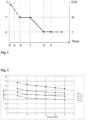
Figure 1 is a diagram showing the regulation of the excess air in a burner ignition step; -
Figure 2 is a diagram showing the relation between the temperature of a burner, the thermal power and excess air; -
Figure 3 is a schematic view of a control and regulation device of a premixed burner wherein the mixing chamber is located downstream of the fan; -
Figure 4 is a schematic view of a control and regulation device of a premixed burner wherein the mixing chamber is placed upstream of the fan. - With reference to the attached drawing tables,
Figure 1 shows how the regulation of a premixed burner 4 occurs in the ignition step thereof, according to the invention. - Initially (section O-A of the diagram of
Fig. 1 ) afan 2 is set in motion at a predetermined rotation speed Vp to create an aeriform flow Fa that activates the burner 4. - Subsequently (section A-B) the aeriform flow Fa is added with a fuel gas flow Fg, mainly and/or essentially composed of hydrogen H2, so as to obtain an air and fuel gas mixture Mag with an excess air factor λ ≥ 2.5.
- In a possible embodiment, a sensor for the volumetric concentration of hydrogen in the air and fuel gas mixture Mag (better described later) may be used to ensure that the excess air factor λ is the desired one.
- It should be noted that the ignition of burner 4 may only take place once the excess air factor λ has taken the desired value.
- The air and fuel gas mixture Mag escaping from the holes of the burner 4 is ignited by means of an
ignition device 5, for example aconventional ignition electrode 5. After the ignition, the air and fuel gas mixture Mag continues maintaining a value of λ ≥ 2.5 for a stabilisation time ts ≥ 5 seconds (section B-C) of the flame. - The inventors have verified that carrying out the ignition of an air and fuel gas mixture Mag with an excess air value λ ≥ 2.5 and maintaining such excess air value λ for at least 5 seconds allows drastically reducing the risk of flashbacks at the time of ignition of the burner 4.
- After the flame stabilisation time has elapsed, the excess air factor λ is progressively reduced, for example in a linear manner, until reaching a λtarget value of 1.3 < λ < 2.5.
- Preferably the excess air factor λ drops to a value λtarget of 1.5 < λ < 2.0 (section C-D-E of the diagram in
Fig. 1 ). - Once the flame stabilisation time has elapsed and after the reduction of the excess air value λ to the value λtarget, the air and fuel gas mixture Mag may begin according to the required thermal power.
- During the step of its normal operation, the temperature Tb of the burner 4 is cyclically monitored, for example at time intervals Δt, to check whether the temperature of the burner 4 remains within predetermined limits, corresponding to a maximum temperature Tsup (above which a flashback may occur) and at a minimum temperature Tinf (below which there is a risk of flame lift-off).
- In defining the minimum Tinf and maximum temperature Tsup within which the burner 4 must remain, both the excess air value λ and the thermal power at which the burner 4 works is taken into account.
- More precisely, with the same excess air λ, the minimum Tinf and maximum temperature Tsup values decrease monotonously as the working thermal power increases.
- In the absence of operating anomalies, more precisely as long as the temperature Tb of the burner 4 remains within values comprised between the minimum Tinf and maximum temperature Tsup, the regulation of the thermal power takes place with an excess air factor λtarget.
- In a possible embodiment, this excess air factor λtarget remains constant; in an alternative embodiment, the excess air factor λtarget varies depending on the thermal power, but always remaining in the range of the excess air values λtarget mentioned above, i.e. 1.3 < λ < 2.5, preferably 1.5 < λ < 2.0.
- In case the working temperature Tb of burner 4 exceeds the predetermined maximum temperature value Tsup, the excess air factor λtarget is progressively increased by a predetermined value Δλ, for example intermittently, until the burner temperature Tb is brought back 4 below such value Tsup.
- On the other hand, when the temperature Tb of the burner 4 drops below a predetermined minimum temperature value Tinf, the excess air factor λtarget is progressively reduced by a predetermined value Δλ, for example intermittently, until the temperature Tb of the burner 4 is brought back above such value Tinf.
- The time interval Δt with which the temperature check Tb of the burner 4 and the possible correction of the excess air λ is carried out may vary according to the time constant of the system, more precisely according to the thermal inertia of the burner 4.
- In a possible embodiment, such time interval Δt = 1 second.
- The inventors have verified that the periodic check of the temperature Tb of the burner 4 and any periodic regulation of the excess air λ of the burned mixture Mag allow keeping the flame stable avoiding, in particular, the risks of flashback when the burner is operated for a long time at reduced powers, without excessively penalising the thermal throughtput thereof.
- The control and regulation method described above may be performed by means of a device 1, for controlling and regulating the operation of a premixed gas burner 4 suitable for burning a fuel gas substantially and/or essentially consisting of hydrogen H2.
- The device 1 comprises a
first duct 11, or combustion air inflow duct Fa, asecond duct 12, or fuel gas inflow duct Fg, avariable speed fan 2, having anintake 21, connected to thefirst duct 11, and adelivery 22. - The speed of
fan 2 may vary according to the required thermal power. - The mixing of the air Fa coming from the
first duct 11 with the fuel gas Fg coming from thesecond duct 12 takes place by means of a Venturitube 3, which may be positioned downstream of the fan (Fig. 3 ) or upstream of the same (Fig. 4 ). - The
second duct 12 is in communication with the narrow section of the Venturitube 3, so that the fuel gas Fg is sucked. A conventional motorised (or more generally modulating)valve 7 is provided, for regulating the flow rate of the fuel gas Fg that passes through thesecond duct 12 and thus for regulating the excess air λ. - A
third duct 13, or air mixture and fuel gas outflow duct Mag is provided, located downstream of the Venturitube 3 which feeds a burner 4. - The burner 4 may be a conventional burner of the perforated surface type, inserted inside a
combustion chamber 41. An ignition device 5 (for example a known ignition electrode) is provided to ignite the air and fuel gas mixture Mag escaping from the Venturitube 3 and reaching the burner 4. - A conventional
non-return valve 14 may be provided upstream of the burner 4. - A
first sensor 61, located inside thefirst duct 11, allows measuring a physical characteristic of the air flow Fa. - In a possible embodiment, the
first sensor 61 is an air mass flow sensor that allows detecting the mass flow rate of the air sucked by thefan 2. - A
second sensor 62, located in the Venturitube 3 or downstream of it, allows measuring the concentration of hydrogen H2 present in the created air and fuel gas mixture Mag. - The first and
second sensors - A
third sensor 63, or temperature sensor, is able to detect the temperature Tb of the burner 4. - A
fourth sensor 64 detects the flame presence on the surface of theburner 41. - Such
fourth sensor 64 may be an optical sensor able to detect the presence of hydroxyl radicals OH. - Alternatively, said
fourth sensor 64 may consist of a low thermal inertia thermocouple, suitable for measuring the temperature of the flame. - In both cases, the
fourth sensor 64 serves only to detect the presence of the flame, but does not provide any detail on the quality of the combustion in place. - A
regulator 8 is provided that receives the signals in input detected by thesensors - The
regulator 8 is able to provide an ignition signal to theignition device 5, a fanspeed regulation signal 2 and a motorised valveopening regulation signal 7. - In the example shown, a
fifth sensor 65 is provided, located inside thesecond duct 12, which allows detecting a physical quantity of the fuel gas flow Fg. - In the example shown, the
fifth sensor 65 is a mass flow sensor of the fuel gas Fg. In the illustrated device, the value of λ is determined by the measurements of themass sensor 61 of the air Fa and thehydrogen concentration sensor 62, while thetemperature sensor 63 is only used to correct the value of λ if the temperature Tb of the burner 4 takes abnormal values. - The fifth
mass sensor 65 of the fuel gas Fg, if present, allows checking whether the information provided by the first twosensors mass sensor 65 may be redundant with respect to the signals already provided by the first twosensors regulator 8 by thismass sensor 65 is important for the purposes of the correct definition of the excess air value λ, in combination with theaforementioned sensors
Claims (11)
- Regulation method of a premixed gas burner (4) fed with hydrogen H2 that provides the steps of:a) starting a fan (2) at a predetermined speed Vp to create an aeriform flow Fa;b) adding a fuel gas flow Fg, mainly and/or essentially composed of hydrogen H2, to said aeriform flow Fa so as to obtain an air and fuel gas mixture Mag with an excess air factor λ ≥ 2.5;c) igniting said air and fuel gas mixture Mag,d) maintaining the combustion of said air and fuel gas mixture Mag for a stabilisation time ts,e) progressively reducing the excess air factor λ up to a value λtarget of 1.3 < λ < 2.5,characterised in that said stabilisation time ts ≥ 5 seconds.
- Method, according to claim 1,
comprising the further steps of:f) checking what the required thermal power is,g) regulating the flow rate of said air and fuel gas mixture Mag according to the required thermal power, maintaining the excess air factor λtarget. - Method, according to claim 2,
comprising the further steps of:h) periodically checking, at each time interval Δt, the temperature Tb of the burner (4):- if said burner temperature Tb exceeds a predetermined maximum temperature value Tsup, increasing the excess air factor λtarget by a predetermined value Δλ;- while if said burner temperature Tb is lower than a predetermined minimum temperature value Tinf, decreasing the excess air factor λtarget by a predetermined value Δλ,i) periodically returning to point h). - Method, according to claim 1, wherein
in said point e) the excess air factor λ is progressively reduced to a preferable value λtarget of 1.5 < λ < 2.0. - Method, according to claim 3, wherein
in said point h) said time interval Δt is preferably equal to 1 second. - Method, according to claim 2, wherein
in said point g) said excess air factor λtarget remains constant. - Method, according to claim 2, wherein
in said point g) said excess air factor λtarget varies depending on the thermal power, always remaining in the range of said excess air values λtarget. - Device (1) for carrying out the regulation method of a premixed gas burner (4), mainly and/or essentially fed by hydrogen H2, comprising:a) a first duct (11) or combustion air inflow duct Fa,b) a second duct (12) or fuel gas inflow duct Fg,c) a variable speed fan (2), having an intake (21) connected to said first duct (11), and a delivery (22),d) a motorised valve (7), to regulate the fuel gas flow rate Fg passing through said second duct (12).e) a Venturi tube (3) for mixing the air Fa coming from said first duct (11) with the fuel gas Fg coming from said second duct (12),f) a third duct (13) or outflow duct of an air and fuel gas mixture Mag, located downstream of said Venturi tube (3),g) at least one burner (4), in particular a burner of the perforated surface type, connected to said third duct (13), said burner (4) being inserted inside a combustion chamber (41),h) an ignition device (5), to ignite said air and fuel gas mixture Mag that escapes from said burner (4),i) a first sensor (61) or air mass flow rate sensor Fa, located inside said first duct (11),j) a second sensor (62) or hydrogen concentration sensor H2, located in said Venturi tube (3) or downstream of said Venturi tube (3),k) a fourth sensor (64) to detect the presence of flame inside said combustion chamber (41),l) a regulator (8) adapted to receive in input:said regulator configured to cause the device to run according to the steps of the method as defined in any of claims 1, 2, and 4-7.- a signal Sc indicative of the required thermal power,- a signal indicative of the air mass flow rate Fa, provided by said first sensor (61),- a signal indicative of the concentration of hydrogen H2 in said air and fuel gas mixture Mag, provided by said second sensor (62),- a signal indicative of the presence of the flame, provided by said fourth sensor (64),and to provide in output:- an ignition signal to the ignition device (5),- a signal for the regulation of the speed of said fan (2), and- a signal for the regulation of the opening of said motorised valve (7),
- Device (1) according to claim 8,further comprising a third sensor (63) or temperature sensor, capable of detecting the temperature Tb of said burner (4),and wherein said regulator (8) comprises an input adapted to further receive a signal indicative of the temperature Tb of the burner (4),and to provide in output:- a signal for the speed regulation of said fan (2),- a signal for the regulation of the opening of said motorised valve (7), and- a signal for the regulation of the thermal power,said regulator configured to cause the device to run according to the steps of the method as defined in claim 3.
- Device (1), according to any claim from 8 onwards,further comprising a fifth sensor (65), or mass flow rate sensor of the fuel gas Fg, located inside said second duct (12),and wherein said regulator (8) comprises an input adapted to further receive a signal indicative of the mass flow rate of the fuel gas Fg.
- Device (1) according to claim 8,
wherein said fourth sensor (64) is an optical sensor or a low thermal inertia thermocouple.
Applications Claiming Priority (2)
| Application Number | Priority Date | Filing Date | Title |
|---|---|---|---|
| IT202100011423 | 2021-05-05 | ||
| PCT/IB2022/053076 WO2022234359A1 (en) | 2021-05-05 | 2022-04-01 | Regulation method of a premix gas burner and control and regulation device for carrying out the method |
Publications (2)
| Publication Number | Publication Date |
|---|---|
| EP4334643A1 EP4334643A1 (en) | 2024-03-13 |
| EP4334643B1 true EP4334643B1 (en) | 2025-02-26 |
Family
ID=77022013
Family Applications (1)
| Application Number | Title | Priority Date | Filing Date |
|---|---|---|---|
| EP22715396.2A Active EP4334643B1 (en) | 2021-05-05 | 2022-04-01 | Regulation method of a premix gas burner and control and regulation device for carrying out the method |
Country Status (4)
| Country | Link |
|---|---|
| US (1) | US12372233B2 (en) |
| EP (1) | EP4334643B1 (en) |
| CN (1) | CN117242300A (en) |
| WO (1) | WO2022234359A1 (en) |
Families Citing this family (1)
| Publication number | Priority date | Publication date | Assignee | Title |
|---|---|---|---|---|
| CN117128512B (en) * | 2023-08-30 | 2024-02-02 | 襄阳中和机电技术有限公司 | Hydrogen fuel burner |
Citations (14)
| Publication number | Priority date | Publication date | Assignee | Title |
|---|---|---|---|---|
| US3671169A (en) | 1971-03-15 | 1972-06-20 | Honeywell Inc | Delayed fuel and post ignition timed burner control system |
| GB1374015A (en) | 1971-09-22 | 1974-11-13 | Cem Comp Electro Mec | Burner apparatus |
| GB1436088A (en) | 1973-09-07 | 1976-05-19 | Landis & Gyr Ag | Control and monitoring devices for oil and gas burners |
| DE19924284A1 (en) | 1998-05-30 | 1999-12-23 | Christoph Nailis | Determining air:fuel ratio or air-ratio Lambda number, for household boiler or motor vehicle |
| DE19941978A1 (en) | 1999-09-03 | 2001-03-15 | Stiebel Eltron Gmbh & Co Kg | Production of synthesis gas for operating fuel cell from fuel involves regulation to ensure over-stoichiometric air supply for start-up, then incomplete combustion after start-up |
| EP1207340A2 (en) | 2000-11-18 | 2002-05-22 | Buderus Heiztechnik GmbH | Method of controling a burner |
| JP2005201648A (en) | 2004-01-13 | 2005-07-28 | Tokyo Gas Co Ltd | Calorific value calculation device and method, and calorific value measurement system |
| EP1571395A1 (en) | 2004-03-02 | 2005-09-07 | Riello S.p.a. | Burner flame control unit |
| DE102004055716A1 (en) | 2004-06-23 | 2006-01-12 | Ebm-Papst Landshut Gmbh | Firing equipment for gas burners has means for determining value dependent on measured temperature and means for regulating generated temperature using characteristic line representing value range corresponding to ideal temperature |
| EP1672280A1 (en) | 2004-12-01 | 2006-06-21 | G. Kromschröder Aktiengesellschaft | method for starting a burner of a gas heating device |
| WO2011117810A2 (en) | 2010-03-23 | 2011-09-29 | Idea S.P.A. | A method and device for controlling the combustive air flow rate of a burner in general. |
| EP3663648A1 (en) | 2018-12-05 | 2020-06-10 | Vaillant GmbH | Method and device for regulating the mixing ratio of combustion air and combustion gas in a combustion process |
| WO2020182902A1 (en) | 2019-03-12 | 2020-09-17 | Bekaert Combustion Technology B.V. | Method to operate a modulating burner |
| WO2021078949A1 (en) * | 2019-10-25 | 2021-04-29 | Bekaert Combustion Technology B.V. | Surface stabilized fully premixed gas premix burner for burning hydrogen gas, and method for starting such burner |
Family Cites Families (13)
| Publication number | Priority date | Publication date | Assignee | Title |
|---|---|---|---|---|
| GB1421551A (en) * | 1972-01-22 | 1976-01-21 | British Gas Corp | Burner for gaseous fuel |
| US4168949A (en) * | 1977-09-26 | 1979-09-25 | Honeywell Inc. | Flame signal stabilization circuit |
| EP0331037B1 (en) * | 1988-02-27 | 1995-01-04 | Osaka Gas Co., Ltd. | Gas burner |
| DE10049203A1 (en) * | 2000-10-05 | 2002-05-23 | Alstom Switzerland Ltd | Process for introducing fuel into a premix burner |
| US6880548B2 (en) * | 2003-06-12 | 2005-04-19 | Honeywell International Inc. | Warm air furnace with premix burner |
| JP2006134643A (en) * | 2004-11-04 | 2006-05-25 | Nissan Motor Co Ltd | Fuel cell system |
| US8408896B2 (en) * | 2007-07-25 | 2013-04-02 | Lummus Technology Inc. | Method, system and apparatus for firing control |
| DE102010044762A1 (en) * | 2010-09-08 | 2012-03-08 | Honeywell Technologies S.A.R.L. | Device for calibrating a gas burner control |
| DE102011117736A1 (en) * | 2011-11-07 | 2013-05-08 | Honeywell Technologies Sarl | Method for operating a gas burner |
| ITBO20120568A1 (en) * | 2012-10-17 | 2014-04-18 | Gas Point S R L | ADJUSTMENT AND CONTROL EQUIPMENT FOR COMBUSTION IN A FUEL GAS BURNER |
| EP3333482B1 (en) * | 2016-12-06 | 2019-09-25 | Honeywell Technologies Sarl | Gas burner controller adapter, gas burner appliance having such a gas burner controller adapter and method for operating such a gas burner appliance |
| WO2019049046A2 (en) * | 2017-09-05 | 2019-03-14 | John Zink Company, Llc | Low nox and co combustion burner method and apparatus |
| US11073281B2 (en) * | 2017-12-29 | 2021-07-27 | Honeywell International Inc. | Closed-loop programming and control of a combustion appliance |
-
2022
- 2022-04-01 EP EP22715396.2A patent/EP4334643B1/en active Active
- 2022-04-01 CN CN202280030573.1A patent/CN117242300A/en active Pending
- 2022-04-01 WO PCT/IB2022/053076 patent/WO2022234359A1/en not_active Ceased
- 2022-04-01 US US18/556,925 patent/US12372233B2/en active Active
Patent Citations (14)
| Publication number | Priority date | Publication date | Assignee | Title |
|---|---|---|---|---|
| US3671169A (en) | 1971-03-15 | 1972-06-20 | Honeywell Inc | Delayed fuel and post ignition timed burner control system |
| GB1374015A (en) | 1971-09-22 | 1974-11-13 | Cem Comp Electro Mec | Burner apparatus |
| GB1436088A (en) | 1973-09-07 | 1976-05-19 | Landis & Gyr Ag | Control and monitoring devices for oil and gas burners |
| DE19924284A1 (en) | 1998-05-30 | 1999-12-23 | Christoph Nailis | Determining air:fuel ratio or air-ratio Lambda number, for household boiler or motor vehicle |
| DE19941978A1 (en) | 1999-09-03 | 2001-03-15 | Stiebel Eltron Gmbh & Co Kg | Production of synthesis gas for operating fuel cell from fuel involves regulation to ensure over-stoichiometric air supply for start-up, then incomplete combustion after start-up |
| EP1207340A2 (en) | 2000-11-18 | 2002-05-22 | Buderus Heiztechnik GmbH | Method of controling a burner |
| JP2005201648A (en) | 2004-01-13 | 2005-07-28 | Tokyo Gas Co Ltd | Calorific value calculation device and method, and calorific value measurement system |
| EP1571395A1 (en) | 2004-03-02 | 2005-09-07 | Riello S.p.a. | Burner flame control unit |
| DE102004055716A1 (en) | 2004-06-23 | 2006-01-12 | Ebm-Papst Landshut Gmbh | Firing equipment for gas burners has means for determining value dependent on measured temperature and means for regulating generated temperature using characteristic line representing value range corresponding to ideal temperature |
| EP1672280A1 (en) | 2004-12-01 | 2006-06-21 | G. Kromschröder Aktiengesellschaft | method for starting a burner of a gas heating device |
| WO2011117810A2 (en) | 2010-03-23 | 2011-09-29 | Idea S.P.A. | A method and device for controlling the combustive air flow rate of a burner in general. |
| EP3663648A1 (en) | 2018-12-05 | 2020-06-10 | Vaillant GmbH | Method and device for regulating the mixing ratio of combustion air and combustion gas in a combustion process |
| WO2020182902A1 (en) | 2019-03-12 | 2020-09-17 | Bekaert Combustion Technology B.V. | Method to operate a modulating burner |
| WO2021078949A1 (en) * | 2019-10-25 | 2021-04-29 | Bekaert Combustion Technology B.V. | Surface stabilized fully premixed gas premix burner for burning hydrogen gas, and method for starting such burner |
Non-Patent Citations (3)
| Title |
|---|
| ANONYMOUS: "DIN EN 15502-1:2012-10 Heizkessel für gasförmige Brennstoffe - Teil 1: Allgemeine Anforderungen und Prüfungen; Deutsche Fassung EN 15502-1:2012", DIN EN NORM, DIN, DE, De, pages 1 - 154, XP009564194, Retrieved from the Internet <URL:https://www.dinmedia.de/de/norm/din-en-15502-1/154349319> |
| ANONYMOUS: "DIN EN 437:2009-09 Prüfgase - Prüfdrücke - Gerätekategorien; Deutsche Fassung EN 437:2003+A1:2009", DIN EN NORM, DIN, DE, DE, pages 1 - 54, XP009564193, Retrieved from the Internet <URL:https://www.dinmedia.de/en/standard/din-en-437/111624338> |
| ANONYMOUS: "Gas Burner Safety Control DKG 972 (0651.10-01-e/03/02)", MANUAL, SATRONIC AG - A HONEYWELL COPMPANY, pages 1 - 6, XP093342041, Retrieved from the Internet <URL:https://honeyvell.energy/wa-data/public/site/DKG/Manual%20Honeywell%20(Satronic)%20DKG972%20(en).pdf> |
Also Published As
| Publication number | Publication date |
|---|---|
| CA3215692A1 (en) | 2022-11-10 |
| US20240200773A1 (en) | 2024-06-20 |
| WO2022234359A1 (en) | 2022-11-10 |
| CN117242300A (en) | 2023-12-15 |
| US12372233B2 (en) | 2025-07-29 |
| EP4334643A1 (en) | 2024-03-13 |
Similar Documents
| Publication | Publication Date | Title |
|---|---|---|
| EP3948077B1 (en) | Method for operating a premix gas burner, a premix gas burner and a boiler | |
| US6640548B2 (en) | Apparatus and method for combusting low quality fuel | |
| US8282389B2 (en) | Modular flare stack and method of flaring waste gas | |
| US4588372A (en) | Flame ionization control of a partially premixed gas burner with regulated secondary air | |
| JP2022524534A (en) | How to operate the adjustment burner | |
| US8020387B2 (en) | Method of operating a burner, including a combustion chamber with a low nitrous oxide emission | |
| US9568195B2 (en) | Combustion efficiency control systems | |
| EP4334643B1 (en) | Regulation method of a premix gas burner and control and regulation device for carrying out the method | |
| US6658856B2 (en) | Hybrid lean premixing catalytic combustion system for gas turbines | |
| CA3215692C (en) | Regulation method of a premix gas burner and control and regulation device for carrying out the method | |
| RU2360183C1 (en) | Automatic modular burner for burning fuel in form of gas-air mixture, burner head and control method of modular burner operation | |
| CN111780154B (en) | Control device and method of gas-fired machine and gas water heater | |
| CN111981479B (en) | Control method and device for premix burner | |
| JP3453973B2 (en) | Control method of premixed combustion device | |
| JPH06101808A (en) | Premixed combustion apparatus and combustion control method thereof | |
| CN209783322U (en) | Flue gas heating device | |
| CA3038928C (en) | High turndown boiler and system and method for controlling a boiler | |
| EP4265965A1 (en) | Control mechanism for a combustion appliance | |
| JP2004519651A (en) | Thermal NOx reduction method in catalytic combustion system | |
| JP2001153363A (en) | Gas turbine combustor |
Legal Events
| Date | Code | Title | Description |
|---|---|---|---|
| STAA | Information on the status of an ep patent application or granted ep patent |
Free format text: STATUS: UNKNOWN |
|
| STAA | Information on the status of an ep patent application or granted ep patent |
Free format text: STATUS: THE INTERNATIONAL PUBLICATION HAS BEEN MADE |
|
| PUAI | Public reference made under article 153(3) epc to a published international application that has entered the european phase |
Free format text: ORIGINAL CODE: 0009012 |
|
| STAA | Information on the status of an ep patent application or granted ep patent |
Free format text: STATUS: REQUEST FOR EXAMINATION WAS MADE |
|
| 17P | Request for examination filed |
Effective date: 20231107 |
|
| AK | Designated contracting states |
Kind code of ref document: A1 Designated state(s): AL AT BE BG CH CY CZ DE DK EE ES FI FR GB GR HR HU IE IS IT LI LT LU LV MC MK MT NL NO PL PT RO RS SE SI SK SM TR |
|
| P01 | Opt-out of the competence of the unified patent court (upc) registered |
Effective date: 20240318 |
|
| DAV | Request for validation of the european patent (deleted) | ||
| DAX | Request for extension of the european patent (deleted) | ||
| GRAP | Despatch of communication of intention to grant a patent |
Free format text: ORIGINAL CODE: EPIDOSNIGR1 |
|
| STAA | Information on the status of an ep patent application or granted ep patent |
Free format text: STATUS: GRANT OF PATENT IS INTENDED |
|
| GRAS | Grant fee paid |
Free format text: ORIGINAL CODE: EPIDOSNIGR3 |
|
| GRAA | (expected) grant |
Free format text: ORIGINAL CODE: 0009210 |
|
| STAA | Information on the status of an ep patent application or granted ep patent |
Free format text: STATUS: THE PATENT HAS BEEN GRANTED |
|
| INTG | Intention to grant announced |
Effective date: 20250103 |
|
| AK | Designated contracting states |
Kind code of ref document: B1 Designated state(s): AL AT BE BG CH CY CZ DE DK EE ES FI FR GB GR HR HU IE IS IT LI LT LU LV MC MK MT NL NO PL PT RO RS SE SI SK SM TR |
|
| REG | Reference to a national code |
Ref country code: GB Ref legal event code: FG4D |
|
| REG | Reference to a national code |
Ref country code: CH Ref legal event code: EP |
|
| REG | Reference to a national code |
Ref country code: DE Ref legal event code: R096 Ref document number: 602022011153 Country of ref document: DE |
|
| REG | Reference to a national code |
Ref country code: IE Ref legal event code: FG4D |
|
| PGFP | Annual fee paid to national office [announced via postgrant information from national office to epo] |
Ref country code: NL Payment date: 20250418 Year of fee payment: 4 |
|
| REG | Reference to a national code |
Ref country code: NL Ref legal event code: FP |
|
| PG25 | Lapsed in a contracting state [announced via postgrant information from national office to epo] |
Ref country code: RS Free format text: LAPSE BECAUSE OF FAILURE TO SUBMIT A TRANSLATION OF THE DESCRIPTION OR TO PAY THE FEE WITHIN THE PRESCRIBED TIME-LIMIT Effective date: 20250526 |
|
| PG25 | Lapsed in a contracting state [announced via postgrant information from national office to epo] |
Ref country code: FI Free format text: LAPSE BECAUSE OF FAILURE TO SUBMIT A TRANSLATION OF THE DESCRIPTION OR TO PAY THE FEE WITHIN THE PRESCRIBED TIME-LIMIT Effective date: 20250226 |
|
| PG25 | Lapsed in a contracting state [announced via postgrant information from national office to epo] |
Ref country code: PL Free format text: LAPSE BECAUSE OF FAILURE TO SUBMIT A TRANSLATION OF THE DESCRIPTION OR TO PAY THE FEE WITHIN THE PRESCRIBED TIME-LIMIT Effective date: 20250226 |
|
| PGFP | Annual fee paid to national office [announced via postgrant information from national office to epo] |
Ref country code: DE Payment date: 20250422 Year of fee payment: 4 |
|
| PG25 | Lapsed in a contracting state [announced via postgrant information from national office to epo] |
Ref country code: ES Free format text: LAPSE BECAUSE OF FAILURE TO SUBMIT A TRANSLATION OF THE DESCRIPTION OR TO PAY THE FEE WITHIN THE PRESCRIBED TIME-LIMIT Effective date: 20250226 |
|
| REG | Reference to a national code |
Ref country code: LT Ref legal event code: MG9D |
|
| PG25 | Lapsed in a contracting state [announced via postgrant information from national office to epo] |
Ref country code: NO Free format text: LAPSE BECAUSE OF FAILURE TO SUBMIT A TRANSLATION OF THE DESCRIPTION OR TO PAY THE FEE WITHIN THE PRESCRIBED TIME-LIMIT Effective date: 20250526 Ref country code: IS Free format text: LAPSE BECAUSE OF FAILURE TO SUBMIT A TRANSLATION OF THE DESCRIPTION OR TO PAY THE FEE WITHIN THE PRESCRIBED TIME-LIMIT Effective date: 20250626 |
|
| PGFP | Annual fee paid to national office [announced via postgrant information from national office to epo] |
Ref country code: IT Payment date: 20250430 Year of fee payment: 4 |
|
| PG25 | Lapsed in a contracting state [announced via postgrant information from national office to epo] |
Ref country code: HR Free format text: LAPSE BECAUSE OF FAILURE TO SUBMIT A TRANSLATION OF THE DESCRIPTION OR TO PAY THE FEE WITHIN THE PRESCRIBED TIME-LIMIT Effective date: 20250226 |
|
| PG25 | Lapsed in a contracting state [announced via postgrant information from national office to epo] |
Ref country code: PT Free format text: LAPSE BECAUSE OF FAILURE TO SUBMIT A TRANSLATION OF THE DESCRIPTION OR TO PAY THE FEE WITHIN THE PRESCRIBED TIME-LIMIT Effective date: 20250626 Ref country code: LV Free format text: LAPSE BECAUSE OF FAILURE TO SUBMIT A TRANSLATION OF THE DESCRIPTION OR TO PAY THE FEE WITHIN THE PRESCRIBED TIME-LIMIT Effective date: 20250226 |
|
| PGFP | Annual fee paid to national office [announced via postgrant information from national office to epo] |
Ref country code: FR Payment date: 20250425 Year of fee payment: 4 |
|
| PG25 | Lapsed in a contracting state [announced via postgrant information from national office to epo] |
Ref country code: BG Free format text: LAPSE BECAUSE OF FAILURE TO SUBMIT A TRANSLATION OF THE DESCRIPTION OR TO PAY THE FEE WITHIN THE PRESCRIBED TIME-LIMIT Effective date: 20250226 Ref country code: GR Free format text: LAPSE BECAUSE OF FAILURE TO SUBMIT A TRANSLATION OF THE DESCRIPTION OR TO PAY THE FEE WITHIN THE PRESCRIBED TIME-LIMIT Effective date: 20250527 |
|
| REG | Reference to a national code |
Ref country code: AT Ref legal event code: MK05 Ref document number: 1770959 Country of ref document: AT Kind code of ref document: T Effective date: 20250226 |
|
| PG25 | Lapsed in a contracting state [announced via postgrant information from national office to epo] |
Ref country code: SE Free format text: LAPSE BECAUSE OF FAILURE TO SUBMIT A TRANSLATION OF THE DESCRIPTION OR TO PAY THE FEE WITHIN THE PRESCRIBED TIME-LIMIT Effective date: 20250226 |
|
| PG25 | Lapsed in a contracting state [announced via postgrant information from national office to epo] |
Ref country code: SM Free format text: LAPSE BECAUSE OF FAILURE TO SUBMIT A TRANSLATION OF THE DESCRIPTION OR TO PAY THE FEE WITHIN THE PRESCRIBED TIME-LIMIT Effective date: 20250226 |
|
| PG25 | Lapsed in a contracting state [announced via postgrant information from national office to epo] |
Ref country code: DK Free format text: LAPSE BECAUSE OF FAILURE TO SUBMIT A TRANSLATION OF THE DESCRIPTION OR TO PAY THE FEE WITHIN THE PRESCRIBED TIME-LIMIT Effective date: 20250226 |
|
| PG25 | Lapsed in a contracting state [announced via postgrant information from national office to epo] |
Ref country code: AT Free format text: LAPSE BECAUSE OF FAILURE TO SUBMIT A TRANSLATION OF THE DESCRIPTION OR TO PAY THE FEE WITHIN THE PRESCRIBED TIME-LIMIT Effective date: 20250226 |
|
| PG25 | Lapsed in a contracting state [announced via postgrant information from national office to epo] |
Ref country code: EE Free format text: LAPSE BECAUSE OF FAILURE TO SUBMIT A TRANSLATION OF THE DESCRIPTION OR TO PAY THE FEE WITHIN THE PRESCRIBED TIME-LIMIT Effective date: 20250226 Ref country code: CZ Free format text: LAPSE BECAUSE OF FAILURE TO SUBMIT A TRANSLATION OF THE DESCRIPTION OR TO PAY THE FEE WITHIN THE PRESCRIBED TIME-LIMIT Effective date: 20250226 |
|
| PG25 | Lapsed in a contracting state [announced via postgrant information from national office to epo] |
Ref country code: RO Free format text: LAPSE BECAUSE OF FAILURE TO SUBMIT A TRANSLATION OF THE DESCRIPTION OR TO PAY THE FEE WITHIN THE PRESCRIBED TIME-LIMIT Effective date: 20250226 |
|
| PG25 | Lapsed in a contracting state [announced via postgrant information from national office to epo] |
Ref country code: SK Free format text: LAPSE BECAUSE OF FAILURE TO SUBMIT A TRANSLATION OF THE DESCRIPTION OR TO PAY THE FEE WITHIN THE PRESCRIBED TIME-LIMIT Effective date: 20250226 |
|
| REG | Reference to a national code |
Ref country code: CH Ref legal event code: H13 Free format text: ST27 STATUS EVENT CODE: U-0-0-H10-H13 (AS PROVIDED BY THE NATIONAL OFFICE) Effective date: 20251125 |
|
| REG | Reference to a national code |
Ref country code: DE Ref legal event code: R026 Ref document number: 602022011153 Country of ref document: DE |
|
| PLBI | Opposition filed |
Free format text: ORIGINAL CODE: 0009260 |
|
| PLAX | Notice of opposition and request to file observation + time limit sent |
Free format text: ORIGINAL CODE: EPIDOSNOBS2 |
|
| TPAC | Observations filed by third parties |
Free format text: ORIGINAL CODE: EPIDOSNTIPA |
|
| PG25 | Lapsed in a contracting state [announced via postgrant information from national office to epo] |
Ref country code: LU Free format text: LAPSE BECAUSE OF NON-PAYMENT OF DUE FEES Effective date: 20250401 |
|
| PG25 | Lapsed in a contracting state [announced via postgrant information from national office to epo] |
Ref country code: MC Free format text: LAPSE BECAUSE OF FAILURE TO SUBMIT A TRANSLATION OF THE DESCRIPTION OR TO PAY THE FEE WITHIN THE PRESCRIBED TIME-LIMIT Effective date: 20250226 |
|
| REG | Reference to a national code |
Ref country code: BE Ref legal event code: MM Effective date: 20250430 |
|
| 26 | Opposition filed |
Opponent name: STOLMAR MATTHIAS Effective date: 20251126 |
|
| PG25 | Lapsed in a contracting state [announced via postgrant information from national office to epo] |
Ref country code: BE Free format text: LAPSE BECAUSE OF NON-PAYMENT OF DUE FEES Effective date: 20250430 |
|
| PG25 | Lapsed in a contracting state [announced via postgrant information from national office to epo] |
Ref country code: CH Free format text: LAPSE BECAUSE OF NON-PAYMENT OF DUE FEES Effective date: 20250430 |
|
| PLAF | Information modified related to communication of a notice of opposition and request to file observations + time limit |
Free format text: ORIGINAL CODE: EPIDOSCOBS2 |
|
| PG25 | Lapsed in a contracting state [announced via postgrant information from national office to epo] |
Ref country code: IE Free format text: LAPSE BECAUSE OF NON-PAYMENT OF DUE FEES Effective date: 20250401 |