EP4334635B1 - Device for storing and supplying cryogenic fluid, vehicle and corresponding method - Google Patents
Device for storing and supplying cryogenic fluid, vehicle and corresponding method Download PDFInfo
- Publication number
- EP4334635B1 EP4334635B1 EP22720351.0A EP22720351A EP4334635B1 EP 4334635 B1 EP4334635 B1 EP 4334635B1 EP 22720351 A EP22720351 A EP 22720351A EP 4334635 B1 EP4334635 B1 EP 4334635B1
- Authority
- EP
- European Patent Office
- Prior art keywords
- tank
- fluid
- heat exchanger
- pressure
- volume
- Prior art date
- Legal status (The legal status is an assumption and is not a legal conclusion. Google has not performed a legal analysis and makes no representation as to the accuracy of the status listed.)
- Active
Links
Images
Classifications
-
- F—MECHANICAL ENGINEERING; LIGHTING; HEATING; WEAPONS; BLASTING
- F17—STORING OR DISTRIBUTING GASES OR LIQUIDS
- F17C—VESSELS FOR CONTAINING OR STORING COMPRESSED, LIQUEFIED OR SOLIDIFIED GASES; FIXED-CAPACITY GAS-HOLDERS; FILLING VESSELS WITH, OR DISCHARGING FROM VESSELS, COMPRESSED, LIQUEFIED, OR SOLIDIFIED GASES
- F17C7/00—Methods or apparatus for discharging liquefied, solidified, or compressed gases from pressure vessels, not covered by another subclass
- F17C7/02—Discharging liquefied gases
- F17C7/04—Discharging liquefied gases with change of state, e.g. vaporisation
-
- F—MECHANICAL ENGINEERING; LIGHTING; HEATING; WEAPONS; BLASTING
- F17—STORING OR DISTRIBUTING GASES OR LIQUIDS
- F17C—VESSELS FOR CONTAINING OR STORING COMPRESSED, LIQUEFIED OR SOLIDIFIED GASES; FIXED-CAPACITY GAS-HOLDERS; FILLING VESSELS WITH, OR DISCHARGING FROM VESSELS, COMPRESSED, LIQUEFIED, OR SOLIDIFIED GASES
- F17C9/00—Methods or apparatus for discharging liquefied or solidified gases from vessels not under pressure
-
- F—MECHANICAL ENGINEERING; LIGHTING; HEATING; WEAPONS; BLASTING
- F17—STORING OR DISTRIBUTING GASES OR LIQUIDS
- F17C—VESSELS FOR CONTAINING OR STORING COMPRESSED, LIQUEFIED OR SOLIDIFIED GASES; FIXED-CAPACITY GAS-HOLDERS; FILLING VESSELS WITH, OR DISCHARGING FROM VESSELS, COMPRESSED, LIQUEFIED, OR SOLIDIFIED GASES
- F17C9/00—Methods or apparatus for discharging liquefied or solidified gases from vessels not under pressure
- F17C9/02—Methods or apparatus for discharging liquefied or solidified gases from vessels not under pressure with change of state, e.g. vaporisation
-
- F—MECHANICAL ENGINEERING; LIGHTING; HEATING; WEAPONS; BLASTING
- F17—STORING OR DISTRIBUTING GASES OR LIQUIDS
- F17C—VESSELS FOR CONTAINING OR STORING COMPRESSED, LIQUEFIED OR SOLIDIFIED GASES; FIXED-CAPACITY GAS-HOLDERS; FILLING VESSELS WITH, OR DISCHARGING FROM VESSELS, COMPRESSED, LIQUEFIED, OR SOLIDIFIED GASES
- F17C2201/00—Vessel construction, in particular geometry, arrangement or size
- F17C2201/01—Shape
- F17C2201/0104—Shape cylindrical
- F17C2201/0109—Shape cylindrical with exteriorly curved end-piece
-
- F—MECHANICAL ENGINEERING; LIGHTING; HEATING; WEAPONS; BLASTING
- F17—STORING OR DISTRIBUTING GASES OR LIQUIDS
- F17C—VESSELS FOR CONTAINING OR STORING COMPRESSED, LIQUEFIED OR SOLIDIFIED GASES; FIXED-CAPACITY GAS-HOLDERS; FILLING VESSELS WITH, OR DISCHARGING FROM VESSELS, COMPRESSED, LIQUEFIED, OR SOLIDIFIED GASES
- F17C2201/00—Vessel construction, in particular geometry, arrangement or size
- F17C2201/03—Orientation
- F17C2201/035—Orientation with substantially horizontal main axis
-
- F—MECHANICAL ENGINEERING; LIGHTING; HEATING; WEAPONS; BLASTING
- F17—STORING OR DISTRIBUTING GASES OR LIQUIDS
- F17C—VESSELS FOR CONTAINING OR STORING COMPRESSED, LIQUEFIED OR SOLIDIFIED GASES; FIXED-CAPACITY GAS-HOLDERS; FILLING VESSELS WITH, OR DISCHARGING FROM VESSELS, COMPRESSED, LIQUEFIED, OR SOLIDIFIED GASES
- F17C2201/00—Vessel construction, in particular geometry, arrangement or size
- F17C2201/05—Size
- F17C2201/054—Size medium (>1 m3)
-
- F—MECHANICAL ENGINEERING; LIGHTING; HEATING; WEAPONS; BLASTING
- F17—STORING OR DISTRIBUTING GASES OR LIQUIDS
- F17C—VESSELS FOR CONTAINING OR STORING COMPRESSED, LIQUEFIED OR SOLIDIFIED GASES; FIXED-CAPACITY GAS-HOLDERS; FILLING VESSELS WITH, OR DISCHARGING FROM VESSELS, COMPRESSED, LIQUEFIED, OR SOLIDIFIED GASES
- F17C2205/00—Vessel construction, in particular mounting arrangements, attachments or identifications means
- F17C2205/03—Fluid connections, filters, valves, closure means or other attachments
- F17C2205/0302—Fittings, valves, filters, or components in connection with the gas storage device
- F17C2205/0323—Valves
- F17C2205/0326—Valves electrically actuated
-
- F—MECHANICAL ENGINEERING; LIGHTING; HEATING; WEAPONS; BLASTING
- F17—STORING OR DISTRIBUTING GASES OR LIQUIDS
- F17C—VESSELS FOR CONTAINING OR STORING COMPRESSED, LIQUEFIED OR SOLIDIFIED GASES; FIXED-CAPACITY GAS-HOLDERS; FILLING VESSELS WITH, OR DISCHARGING FROM VESSELS, COMPRESSED, LIQUEFIED, OR SOLIDIFIED GASES
- F17C2205/00—Vessel construction, in particular mounting arrangements, attachments or identifications means
- F17C2205/03—Fluid connections, filters, valves, closure means or other attachments
- F17C2205/0302—Fittings, valves, filters, or components in connection with the gas storage device
- F17C2205/0323—Valves
- F17C2205/0332—Safety valves or pressure relief valves
-
- F—MECHANICAL ENGINEERING; LIGHTING; HEATING; WEAPONS; BLASTING
- F17—STORING OR DISTRIBUTING GASES OR LIQUIDS
- F17C—VESSELS FOR CONTAINING OR STORING COMPRESSED, LIQUEFIED OR SOLIDIFIED GASES; FIXED-CAPACITY GAS-HOLDERS; FILLING VESSELS WITH, OR DISCHARGING FROM VESSELS, COMPRESSED, LIQUEFIED, OR SOLIDIFIED GASES
- F17C2205/00—Vessel construction, in particular mounting arrangements, attachments or identifications means
- F17C2205/03—Fluid connections, filters, valves, closure means or other attachments
- F17C2205/0302—Fittings, valves, filters, or components in connection with the gas storage device
- F17C2205/0323—Valves
- F17C2205/0335—Check-valves or non-return valves
-
- F—MECHANICAL ENGINEERING; LIGHTING; HEATING; WEAPONS; BLASTING
- F17—STORING OR DISTRIBUTING GASES OR LIQUIDS
- F17C—VESSELS FOR CONTAINING OR STORING COMPRESSED, LIQUEFIED OR SOLIDIFIED GASES; FIXED-CAPACITY GAS-HOLDERS; FILLING VESSELS WITH, OR DISCHARGING FROM VESSELS, COMPRESSED, LIQUEFIED, OR SOLIDIFIED GASES
- F17C2205/00—Vessel construction, in particular mounting arrangements, attachments or identifications means
- F17C2205/03—Fluid connections, filters, valves, closure means or other attachments
- F17C2205/0302—Fittings, valves, filters, or components in connection with the gas storage device
- F17C2205/0338—Pressure regulators
-
- F—MECHANICAL ENGINEERING; LIGHTING; HEATING; WEAPONS; BLASTING
- F17—STORING OR DISTRIBUTING GASES OR LIQUIDS
- F17C—VESSELS FOR CONTAINING OR STORING COMPRESSED, LIQUEFIED OR SOLIDIFIED GASES; FIXED-CAPACITY GAS-HOLDERS; FILLING VESSELS WITH, OR DISCHARGING FROM VESSELS, COMPRESSED, LIQUEFIED, OR SOLIDIFIED GASES
- F17C2221/00—Handled fluid, in particular type of fluid
- F17C2221/01—Pure fluids
- F17C2221/012—Hydrogen
-
- F—MECHANICAL ENGINEERING; LIGHTING; HEATING; WEAPONS; BLASTING
- F17—STORING OR DISTRIBUTING GASES OR LIQUIDS
- F17C—VESSELS FOR CONTAINING OR STORING COMPRESSED, LIQUEFIED OR SOLIDIFIED GASES; FIXED-CAPACITY GAS-HOLDERS; FILLING VESSELS WITH, OR DISCHARGING FROM VESSELS, COMPRESSED, LIQUEFIED, OR SOLIDIFIED GASES
- F17C2223/00—Handled fluid before transfer, i.e. state of fluid when stored in the vessel or before transfer from the vessel
- F17C2223/01—Handled fluid before transfer, i.e. state of fluid when stored in the vessel or before transfer from the vessel characterised by the phase
- F17C2223/0146—Two-phase
- F17C2223/0153—Liquefied gas, e.g. LPG, GPL
- F17C2223/0161—Liquefied gas, e.g. LPG, GPL cryogenic, e.g. LNG, GNL, PLNG
-
- F—MECHANICAL ENGINEERING; LIGHTING; HEATING; WEAPONS; BLASTING
- F17—STORING OR DISTRIBUTING GASES OR LIQUIDS
- F17C—VESSELS FOR CONTAINING OR STORING COMPRESSED, LIQUEFIED OR SOLIDIFIED GASES; FIXED-CAPACITY GAS-HOLDERS; FILLING VESSELS WITH, OR DISCHARGING FROM VESSELS, COMPRESSED, LIQUEFIED, OR SOLIDIFIED GASES
- F17C2223/00—Handled fluid before transfer, i.e. state of fluid when stored in the vessel or before transfer from the vessel
- F17C2223/01—Handled fluid before transfer, i.e. state of fluid when stored in the vessel or before transfer from the vessel characterised by the phase
- F17C2223/0146—Two-phase
- F17C2223/0153—Liquefied gas, e.g. LPG, GPL
- F17C2223/0169—Liquefied gas, e.g. LPG, GPL subcooled
-
- F—MECHANICAL ENGINEERING; LIGHTING; HEATING; WEAPONS; BLASTING
- F17—STORING OR DISTRIBUTING GASES OR LIQUIDS
- F17C—VESSELS FOR CONTAINING OR STORING COMPRESSED, LIQUEFIED OR SOLIDIFIED GASES; FIXED-CAPACITY GAS-HOLDERS; FILLING VESSELS WITH, OR DISCHARGING FROM VESSELS, COMPRESSED, LIQUEFIED, OR SOLIDIFIED GASES
- F17C2223/00—Handled fluid before transfer, i.e. state of fluid when stored in the vessel or before transfer from the vessel
- F17C2223/03—Handled fluid before transfer, i.e. state of fluid when stored in the vessel or before transfer from the vessel characterised by the pressure level
- F17C2223/033—Small pressure, e.g. for liquefied gas
-
- F—MECHANICAL ENGINEERING; LIGHTING; HEATING; WEAPONS; BLASTING
- F17—STORING OR DISTRIBUTING GASES OR LIQUIDS
- F17C—VESSELS FOR CONTAINING OR STORING COMPRESSED, LIQUEFIED OR SOLIDIFIED GASES; FIXED-CAPACITY GAS-HOLDERS; FILLING VESSELS WITH, OR DISCHARGING FROM VESSELS, COMPRESSED, LIQUEFIED, OR SOLIDIFIED GASES
- F17C2223/00—Handled fluid before transfer, i.e. state of fluid when stored in the vessel or before transfer from the vessel
- F17C2223/03—Handled fluid before transfer, i.e. state of fluid when stored in the vessel or before transfer from the vessel characterised by the pressure level
- F17C2223/035—High pressure (>10 bar)
-
- F—MECHANICAL ENGINEERING; LIGHTING; HEATING; WEAPONS; BLASTING
- F17—STORING OR DISTRIBUTING GASES OR LIQUIDS
- F17C—VESSELS FOR CONTAINING OR STORING COMPRESSED, LIQUEFIED OR SOLIDIFIED GASES; FIXED-CAPACITY GAS-HOLDERS; FILLING VESSELS WITH, OR DISCHARGING FROM VESSELS, COMPRESSED, LIQUEFIED, OR SOLIDIFIED GASES
- F17C2223/00—Handled fluid before transfer, i.e. state of fluid when stored in the vessel or before transfer from the vessel
- F17C2223/04—Handled fluid before transfer, i.e. state of fluid when stored in the vessel or before transfer from the vessel characterised by other properties of handled fluid before transfer
- F17C2223/041—Stratification
-
- F—MECHANICAL ENGINEERING; LIGHTING; HEATING; WEAPONS; BLASTING
- F17—STORING OR DISTRIBUTING GASES OR LIQUIDS
- F17C—VESSELS FOR CONTAINING OR STORING COMPRESSED, LIQUEFIED OR SOLIDIFIED GASES; FIXED-CAPACITY GAS-HOLDERS; FILLING VESSELS WITH, OR DISCHARGING FROM VESSELS, COMPRESSED, LIQUEFIED, OR SOLIDIFIED GASES
- F17C2223/00—Handled fluid before transfer, i.e. state of fluid when stored in the vessel or before transfer from the vessel
- F17C2223/04—Handled fluid before transfer, i.e. state of fluid when stored in the vessel or before transfer from the vessel characterised by other properties of handled fluid before transfer
- F17C2223/042—Localisation of the removal point
- F17C2223/043—Localisation of the removal point in the gas
-
- F—MECHANICAL ENGINEERING; LIGHTING; HEATING; WEAPONS; BLASTING
- F17—STORING OR DISTRIBUTING GASES OR LIQUIDS
- F17C—VESSELS FOR CONTAINING OR STORING COMPRESSED, LIQUEFIED OR SOLIDIFIED GASES; FIXED-CAPACITY GAS-HOLDERS; FILLING VESSELS WITH, OR DISCHARGING FROM VESSELS, COMPRESSED, LIQUEFIED, OR SOLIDIFIED GASES
- F17C2223/00—Handled fluid before transfer, i.e. state of fluid when stored in the vessel or before transfer from the vessel
- F17C2223/04—Handled fluid before transfer, i.e. state of fluid when stored in the vessel or before transfer from the vessel characterised by other properties of handled fluid before transfer
- F17C2223/042—Localisation of the removal point
- F17C2223/046—Localisation of the removal point in the liquid
-
- F—MECHANICAL ENGINEERING; LIGHTING; HEATING; WEAPONS; BLASTING
- F17—STORING OR DISTRIBUTING GASES OR LIQUIDS
- F17C—VESSELS FOR CONTAINING OR STORING COMPRESSED, LIQUEFIED OR SOLIDIFIED GASES; FIXED-CAPACITY GAS-HOLDERS; FILLING VESSELS WITH, OR DISCHARGING FROM VESSELS, COMPRESSED, LIQUEFIED, OR SOLIDIFIED GASES
- F17C2227/00—Transfer of fluids, i.e. method or means for transferring the fluid; Heat exchange with the fluid
- F17C2227/01—Propulsion of the fluid
- F17C2227/0107—Propulsion of the fluid by pressurising the ullage
-
- F—MECHANICAL ENGINEERING; LIGHTING; HEATING; WEAPONS; BLASTING
- F17—STORING OR DISTRIBUTING GASES OR LIQUIDS
- F17C—VESSELS FOR CONTAINING OR STORING COMPRESSED, LIQUEFIED OR SOLIDIFIED GASES; FIXED-CAPACITY GAS-HOLDERS; FILLING VESSELS WITH, OR DISCHARGING FROM VESSELS, COMPRESSED, LIQUEFIED, OR SOLIDIFIED GASES
- F17C2227/00—Transfer of fluids, i.e. method or means for transferring the fluid; Heat exchange with the fluid
- F17C2227/03—Heat exchange with the fluid
- F17C2227/0302—Heat exchange with the fluid by heating
-
- F—MECHANICAL ENGINEERING; LIGHTING; HEATING; WEAPONS; BLASTING
- F17—STORING OR DISTRIBUTING GASES OR LIQUIDS
- F17C—VESSELS FOR CONTAINING OR STORING COMPRESSED, LIQUEFIED OR SOLIDIFIED GASES; FIXED-CAPACITY GAS-HOLDERS; FILLING VESSELS WITH, OR DISCHARGING FROM VESSELS, COMPRESSED, LIQUEFIED, OR SOLIDIFIED GASES
- F17C2227/00—Transfer of fluids, i.e. method or means for transferring the fluid; Heat exchange with the fluid
- F17C2227/03—Heat exchange with the fluid
- F17C2227/0302—Heat exchange with the fluid by heating
- F17C2227/0306—Heat exchange with the fluid by heating using the same fluid
-
- F—MECHANICAL ENGINEERING; LIGHTING; HEATING; WEAPONS; BLASTING
- F17—STORING OR DISTRIBUTING GASES OR LIQUIDS
- F17C—VESSELS FOR CONTAINING OR STORING COMPRESSED, LIQUEFIED OR SOLIDIFIED GASES; FIXED-CAPACITY GAS-HOLDERS; FILLING VESSELS WITH, OR DISCHARGING FROM VESSELS, COMPRESSED, LIQUEFIED, OR SOLIDIFIED GASES
- F17C2227/00—Transfer of fluids, i.e. method or means for transferring the fluid; Heat exchange with the fluid
- F17C2227/03—Heat exchange with the fluid
- F17C2227/0302—Heat exchange with the fluid by heating
- F17C2227/0309—Heat exchange with the fluid by heating using another fluid
- F17C2227/0311—Air heating
-
- F—MECHANICAL ENGINEERING; LIGHTING; HEATING; WEAPONS; BLASTING
- F17—STORING OR DISTRIBUTING GASES OR LIQUIDS
- F17C—VESSELS FOR CONTAINING OR STORING COMPRESSED, LIQUEFIED OR SOLIDIFIED GASES; FIXED-CAPACITY GAS-HOLDERS; FILLING VESSELS WITH, OR DISCHARGING FROM VESSELS, COMPRESSED, LIQUEFIED, OR SOLIDIFIED GASES
- F17C2227/00—Transfer of fluids, i.e. method or means for transferring the fluid; Heat exchange with the fluid
- F17C2227/03—Heat exchange with the fluid
- F17C2227/0367—Localisation of heat exchange
- F17C2227/0369—Localisation of heat exchange in or on a vessel
- F17C2227/0376—Localisation of heat exchange in or on a vessel in wall contact
- F17C2227/0383—Localisation of heat exchange in or on a vessel in wall contact outside the vessel
-
- F—MECHANICAL ENGINEERING; LIGHTING; HEATING; WEAPONS; BLASTING
- F17—STORING OR DISTRIBUTING GASES OR LIQUIDS
- F17C—VESSELS FOR CONTAINING OR STORING COMPRESSED, LIQUEFIED OR SOLIDIFIED GASES; FIXED-CAPACITY GAS-HOLDERS; FILLING VESSELS WITH, OR DISCHARGING FROM VESSELS, COMPRESSED, LIQUEFIED, OR SOLIDIFIED GASES
- F17C2227/00—Transfer of fluids, i.e. method or means for transferring the fluid; Heat exchange with the fluid
- F17C2227/04—Methods for emptying or filling
- F17C2227/047—Methods for emptying or filling by repeating a process cycle
-
- F—MECHANICAL ENGINEERING; LIGHTING; HEATING; WEAPONS; BLASTING
- F17—STORING OR DISTRIBUTING GASES OR LIQUIDS
- F17C—VESSELS FOR CONTAINING OR STORING COMPRESSED, LIQUEFIED OR SOLIDIFIED GASES; FIXED-CAPACITY GAS-HOLDERS; FILLING VESSELS WITH, OR DISCHARGING FROM VESSELS, COMPRESSED, LIQUEFIED, OR SOLIDIFIED GASES
- F17C2250/00—Accessories; Control means; Indicating, measuring or monitoring of parameters
- F17C2250/03—Control means
-
- F—MECHANICAL ENGINEERING; LIGHTING; HEATING; WEAPONS; BLASTING
- F17—STORING OR DISTRIBUTING GASES OR LIQUIDS
- F17C—VESSELS FOR CONTAINING OR STORING COMPRESSED, LIQUEFIED OR SOLIDIFIED GASES; FIXED-CAPACITY GAS-HOLDERS; FILLING VESSELS WITH, OR DISCHARGING FROM VESSELS, COMPRESSED, LIQUEFIED, OR SOLIDIFIED GASES
- F17C2250/00—Accessories; Control means; Indicating, measuring or monitoring of parameters
- F17C2250/04—Indicating or measuring of parameters as input values
- F17C2250/0404—Parameters indicated or measured
- F17C2250/043—Pressure
-
- F—MECHANICAL ENGINEERING; LIGHTING; HEATING; WEAPONS; BLASTING
- F17—STORING OR DISTRIBUTING GASES OR LIQUIDS
- F17C—VESSELS FOR CONTAINING OR STORING COMPRESSED, LIQUEFIED OR SOLIDIFIED GASES; FIXED-CAPACITY GAS-HOLDERS; FILLING VESSELS WITH, OR DISCHARGING FROM VESSELS, COMPRESSED, LIQUEFIED, OR SOLIDIFIED GASES
- F17C2250/00—Accessories; Control means; Indicating, measuring or monitoring of parameters
- F17C2250/04—Indicating or measuring of parameters as input values
- F17C2250/0404—Parameters indicated or measured
- F17C2250/0439—Temperature
-
- F—MECHANICAL ENGINEERING; LIGHTING; HEATING; WEAPONS; BLASTING
- F17—STORING OR DISTRIBUTING GASES OR LIQUIDS
- F17C—VESSELS FOR CONTAINING OR STORING COMPRESSED, LIQUEFIED OR SOLIDIFIED GASES; FIXED-CAPACITY GAS-HOLDERS; FILLING VESSELS WITH, OR DISCHARGING FROM VESSELS, COMPRESSED, LIQUEFIED, OR SOLIDIFIED GASES
- F17C2250/00—Accessories; Control means; Indicating, measuring or monitoring of parameters
- F17C2250/06—Controlling or regulating of parameters as output values
- F17C2250/0605—Parameters
- F17C2250/0626—Pressure
-
- F—MECHANICAL ENGINEERING; LIGHTING; HEATING; WEAPONS; BLASTING
- F17—STORING OR DISTRIBUTING GASES OR LIQUIDS
- F17C—VESSELS FOR CONTAINING OR STORING COMPRESSED, LIQUEFIED OR SOLIDIFIED GASES; FIXED-CAPACITY GAS-HOLDERS; FILLING VESSELS WITH, OR DISCHARGING FROM VESSELS, COMPRESSED, LIQUEFIED, OR SOLIDIFIED GASES
- F17C2250/00—Accessories; Control means; Indicating, measuring or monitoring of parameters
- F17C2250/06—Controlling or regulating of parameters as output values
- F17C2250/0605—Parameters
- F17C2250/0631—Temperature
-
- F—MECHANICAL ENGINEERING; LIGHTING; HEATING; WEAPONS; BLASTING
- F17—STORING OR DISTRIBUTING GASES OR LIQUIDS
- F17C—VESSELS FOR CONTAINING OR STORING COMPRESSED, LIQUEFIED OR SOLIDIFIED GASES; FIXED-CAPACITY GAS-HOLDERS; FILLING VESSELS WITH, OR DISCHARGING FROM VESSELS, COMPRESSED, LIQUEFIED, OR SOLIDIFIED GASES
- F17C2250/00—Accessories; Control means; Indicating, measuring or monitoring of parameters
- F17C2250/06—Controlling or regulating of parameters as output values
- F17C2250/0605—Parameters
- F17C2250/0636—Flow or movement of content
-
- F—MECHANICAL ENGINEERING; LIGHTING; HEATING; WEAPONS; BLASTING
- F17—STORING OR DISTRIBUTING GASES OR LIQUIDS
- F17C—VESSELS FOR CONTAINING OR STORING COMPRESSED, LIQUEFIED OR SOLIDIFIED GASES; FIXED-CAPACITY GAS-HOLDERS; FILLING VESSELS WITH, OR DISCHARGING FROM VESSELS, COMPRESSED, LIQUEFIED, OR SOLIDIFIED GASES
- F17C2260/00—Purposes of gas storage and gas handling
- F17C2260/05—Improving chemical properties
- F17C2260/056—Improving fluid characteristics
-
- F—MECHANICAL ENGINEERING; LIGHTING; HEATING; WEAPONS; BLASTING
- F17—STORING OR DISTRIBUTING GASES OR LIQUIDS
- F17C—VESSELS FOR CONTAINING OR STORING COMPRESSED, LIQUEFIED OR SOLIDIFIED GASES; FIXED-CAPACITY GAS-HOLDERS; FILLING VESSELS WITH, OR DISCHARGING FROM VESSELS, COMPRESSED, LIQUEFIED, OR SOLIDIFIED GASES
- F17C2265/00—Effects achieved by gas storage or gas handling
- F17C2265/06—Fluid distribution
-
- F—MECHANICAL ENGINEERING; LIGHTING; HEATING; WEAPONS; BLASTING
- F17—STORING OR DISTRIBUTING GASES OR LIQUIDS
- F17C—VESSELS FOR CONTAINING OR STORING COMPRESSED, LIQUEFIED OR SOLIDIFIED GASES; FIXED-CAPACITY GAS-HOLDERS; FILLING VESSELS WITH, OR DISCHARGING FROM VESSELS, COMPRESSED, LIQUEFIED, OR SOLIDIFIED GASES
- F17C2265/00—Effects achieved by gas storage or gas handling
- F17C2265/06—Fluid distribution
- F17C2265/063—Fluid distribution for supply of refuelling stations
-
- F—MECHANICAL ENGINEERING; LIGHTING; HEATING; WEAPONS; BLASTING
- F17—STORING OR DISTRIBUTING GASES OR LIQUIDS
- F17C—VESSELS FOR CONTAINING OR STORING COMPRESSED, LIQUEFIED OR SOLIDIFIED GASES; FIXED-CAPACITY GAS-HOLDERS; FILLING VESSELS WITH, OR DISCHARGING FROM VESSELS, COMPRESSED, LIQUEFIED, OR SOLIDIFIED GASES
- F17C2270/00—Applications
- F17C2270/01—Applications for fluid transport or storage
- F17C2270/0165—Applications for fluid transport or storage on the road
- F17C2270/0168—Applications for fluid transport or storage on the road by vehicles
- F17C2270/0171—Trucks
-
- Y—GENERAL TAGGING OF NEW TECHNOLOGICAL DEVELOPMENTS; GENERAL TAGGING OF CROSS-SECTIONAL TECHNOLOGIES SPANNING OVER SEVERAL SECTIONS OF THE IPC; TECHNICAL SUBJECTS COVERED BY FORMER USPC CROSS-REFERENCE ART COLLECTIONS [XRACs] AND DIGESTS
- Y02—TECHNOLOGIES OR APPLICATIONS FOR MITIGATION OR ADAPTATION AGAINST CLIMATE CHANGE
- Y02E—REDUCTION OF GREENHOUSE GAS [GHG] EMISSIONS, RELATED TO ENERGY GENERATION, TRANSMISSION OR DISTRIBUTION
- Y02E60/00—Enabling technologies; Technologies with a potential or indirect contribution to GHG emissions mitigation
- Y02E60/30—Hydrogen technology
- Y02E60/32—Hydrogen storage
Definitions
- An aim of the present invention is to overcome all or part of the drawbacks of the prior art noted above.
Landscapes
- Engineering & Computer Science (AREA)
- Mechanical Engineering (AREA)
- General Engineering & Computer Science (AREA)
- Filling Or Discharging Of Gas Storage Vessels (AREA)
Description
L'invention concerne un dispositif de stockage et de fourniture de fluide cryogénique, un véhicule comprenant un tel dispositif et un procédé correspondant.The invention relates to a device for storing and supplying cryogenic fluid, a vehicle comprising such a device and a corresponding method.
L'invention concerne plus particulièrement un dispositif de stockage et de fourniture de fluide cryogénique, notamment dispositif embarqué de stockage et de fourniture d'hydrogène liquéfié, comprenant un réservoir cryogénique de stockage de fluide liquéfié, un circuit de soutirage, le dispositif comprenant un système de pressurisation du réservoir comprenant une conduite de pressurisation ayant deux extrémités reliées respectivement aux parties supérieure et inférieure du réservoir, un échangeur de chaleur de vaporisation et un ensemble de vanne(s) configuré pour permettre le soutirage de liquide du réservoir, son réchauffage dans l'échangeur (4) de chaleur de vaporisation et sa réintroduction dans le réservoir.The invention relates more particularly to a device for storing and supplying cryogenic fluid, in particular an on-board device for storing and supplying liquefied hydrogen, comprising a cryogenic tank for storing liquefied fluid, a withdrawal circuit, the device comprising a system for pressurizing the tank comprising a pressurization pipe having two ends connected respectively to the upper and lower parts of the tank, a vaporization heat exchanger and a set of valve(s) configured to allow the withdrawal of liquid from the tank, its reheating in the vaporization heat exchanger (4) and its reintroduction into the tank.
La pressurisation de réservoirs cryogéniques, notamment de semi-remorques d'hydrogène liquéfié est réalisée généralement par soutirage de liquide, vaporisation en point bas, et réinjection du gaz réchauffé en point haut du réservoir par le phénomène de thermosiphon.The pressurization of cryogenic tanks, particularly semi-trailers of liquefied hydrogen, is generally carried out by drawing off liquid, vaporizing at the low point, and reinjecting the heated gas at the high point of the tank by the thermosiphon phenomenon.
Cette pressurisation augmente l'énergie interne du système et conduit à une augmentation de la pression de saturation du liquide (et de sa température). Ceci peut être problématique dans des applications où le client spécifie une température maximale de livraison du fluide.This pressurization increases the internal energy of the system and leads to an increase in the saturation pressure of the liquid (and its temperature). This can be problematic in applications where the customer specifies a maximum delivery temperature of the fluid.
La température du gaz injecté dans le réservoir est un paramètre important d'optimisation. Pour limiter l'énergie apportée par unité de pressurisation, il est avantageux d'injecter le gaz à la plus haute température possible et de s'assurer d'un fort gradient thermique vertical dans le réservoir (stratification) pour conserver le liquide en partie inférieure à la température la plus froide possible. Un exemple de dispositif de stockage et de fourniture de fluide cryogénique est divulgué dans le document
Un but de la présente invention est de pallier tout ou partie des inconvénients de l'art antérieur relevés ci-dessus.An aim of the present invention is to overcome all or part of the drawbacks of the prior art noted above.
A cette fin, le dispositif selon l'invention, par ailleurs conforme à la définition générique qu'en donne le préambule ci-dessus, est essentiellement caractérisé en ce que le système de pressurisation du réservoir est configuré pour soutirer un volume déterminé de fluide du réservoir, stocker et isoler ce volume dans l'échangeur de chaleur de vaporisation jusqu'à ce que le volume de fluide atteigne des conditions de température et/ou de pression déterminées avant de réinjecter ce volume de fluide dans le réservoir, la conduite de pressurisation comprenant un organe de limitation du débit et/ou de la pression du volume de fluide réinjecté.To this end, the device according to the invention, moreover in accordance with the generic definition given in the preamble above, is essentially characterized in that the reservoir pressurization system is configured to draw a determined volume of fluid from the reservoir, store and isolate this volume in the vaporization heat exchanger until the volume of fluid reaches determined temperature and/or pressure conditions before reinjecting this volume of fluid into the reservoir, the pressurization pipe comprising a flow rate limiting member. and/or the pressure of the volume of fluid reinjected.
Par ailleurs, des modes de réalisation de l'invention peuvent comporter l'une ou plusieurs des caractéristiques suivantes :
- l'ensemble de vanne(s) de la conduite de pressurisation comprend deux vannes d'isolation disposées de part et d'autre de l'échangeur de chaleur de vaporisation,
- l'organe de limitation du débit et/ou de la pression est disposé en parallèle de la vannes d'isolation située entre l'échangeur de chaleur de vaporisation et l'extrémité supérieure du réservoir,
- l'organe de limitation du débit et/ou de la pression comprend une vanne de régulation de pression à un niveau déterminé fixe ou réglable,
- l'organe de limitation du débit et/ou de la pression est constitué par une des deux vannes d'isolation et/ou une vanne distincte des deux vannes d'isolation,
- la conduite de pressurisation comprend un stockage tampon communiquant avec une sortie de l'échangeur de chaleur et configuré pour accueillir une partie du volume de fluide,
- le stockage tampon est raccordé d'une part en amont de la vanne d'isolation située entre l'échangeur de chaleur de vaporisation et l'extrémité supérieure du réservoir et, d'autre part, en aval de l'échangeur de chaleur de vaporisation,
- la conduite de pressurisation comporte une soupape de sécurité sensible à la pression ayant une première extrémité communiquant avec une sortie de l'échangeur de chaleur de vaporisation et une seconde extrémité de décharge reliée à une zone de décharge telle que l'atmosphère ou le réservoir,
- la conduite de pressurisation comporte deux échangeurs de chaleur de vaporisation disposés en parallèle,
- le dispositif comprend un contrôleur électronique programmable configuré pour piloter tout ou partie de l'ensemble de vannes et éventuellement l'organe de limitation du débit et/ou de la pression, par exemple en fonction de la pression dans le réservoir.
- the pressurization line valve assembly includes two isolation valves arranged on either side of the vaporization heat exchanger,
- the flow and/or pressure limiting member is arranged in parallel with the isolation valves located between the vaporization heat exchanger and the upper end of the tank,
- the flow and/or pressure limiting member comprises a pressure regulating valve at a fixed or adjustable determined level,
- the flow and/or pressure limiting device consists of one of the two isolation valves and/or a valve separate from the two isolation valves,
- the pressurization line includes a buffer storage communicating with an outlet of the heat exchanger and configured to accommodate a portion of the fluid volume,
- the buffer storage is connected on the one hand upstream of the isolation valve located between the vaporization heat exchanger and the upper end of the tank and, on the other hand, downstream of the vaporization heat exchanger,
- the pressurizing line includes a pressure sensitive safety valve having a first end communicating with an outlet of the vaporization heat exchanger and a second discharge end connected to a discharge zone such as the atmosphere or the reservoir,
- the pressurization line has two vaporization heat exchangers arranged in parallel,
- the device comprises a programmable electronic controller configured to control all or part of the set of valves and possibly the flow and/or pressure limiting member, for example as a function of the pressure in the tank.
L'invention concerne également un véhicule, notamment camion transportant un dispositif selon l'une quelconque des caractéristiques ci-dessus ou ci-dessous.The invention also relates to a vehicle, in particular a truck transporting a device according to any one of the characteristics above or below.
L'invention concerne également un procédé de régulation de la pression dans un réservoir cryogénique d'un tel dispositif de stockage et de fourniture de fluide cryogénique ou d'un tel véhicule, comprenant une étape de soutirage d'un volume déterminé de fluide du réservoir, une étape de stockage et d'isolation de ce volume dans l'échangeur de chaleur de vaporisation et, lorsque le volume de fluide atteint par réchauffement spontané une température et/ou une pression prédéterminée(s), une étape de réinjection de ce volume de fluide dans le réservoir.The invention also relates to a method for regulating the pressure in a cryogenic tank of such a cryogenic fluid storage and supply device or such a vehicle, comprising a step of withdrawing a determined volume of fluid from the tank, a step of storing and isolating this volume in the vaporization heat exchanger and, when the volume of fluid reaches a predetermined temperature and/or pressure by spontaneous heating, a step of reinjecting this volume of fluid into the reservoir.
L'invention peut concerner également tout dispositif ou procédé alternatif comprenant toute combinaison des caractéristiques ci-dessus ou ci-dessous dans le cadre des revendications.The invention may also relate to any alternative device or method comprising any combination of the above or below features within the scope of the claims.
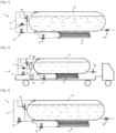
D'autres particularités et avantages apparaîtront à la lecture de la description ci-après, faite en référence aux figures dans lesquelles :
- [
Fig.1 ] représente une vue en coupe schématique et partielle illustrant un premier exemple de structure et de fonctionnement d'un dispositif ne faisant pas partie de l'invention, - [
Fig.2 ] représente une vue en coupe schématique et partielle illustrant un véhicule muni d'un deuxième exemple de structure et de fonctionnement qui est un dispositif selon l'invention, - [
Fig.3 ] représente une vue en coupe schématique et partielle illustrant un troisième exemple de structure et de fonctionnement d'un dispositif ne faisant pas partie de l'invention.
- [
Fig.1 ] represents a schematic and partial sectional view illustrating a first example of structure and operation of a device not forming part of the invention, - [
Fig.2 ] represents a schematic and partial sectional view illustrating a vehicle provided with a second example of structure and operation which is a device according to the invention, - [
Fig.3 ] represents a schematic and partial sectional view illustrating a third example of structure and operation of a device not forming part of the invention.
Le dispositif 1 de stockage et de fourniture de fluide cryogénique illustré peut être un dispositif embarqué de stockage et de fourniture d'hydrogène liquéfié.The illustrated cryogenic fluid storage and
Le dispositif 1 comprend un réservoir 2 cryogénique de stockage de fluide liquéfié (par exemple un réservoir à double parois isolé sous vide) et circuit 10 de soutirage. Dans l'exemple schématique représenté le circuit de soutirage comprend une conduite de soutirage de liquide mais, bien entendu, en variante ou en combinaison, une conduite de soutirage de gaz peut être envisagée. Idem pour le remplissage (même circuit que pour soutirage ou circuit distinct).The
Le dispositif 1 comprend en outre un système de pressurisation du réservoir 2 muni d'une conduite 3 de pressurisation ayant deux extrémités reliées respectivement aux parties supérieure et inférieure du réservoir 2. Cette conduite 3 de pressurisation comprend un échangeur 4 de chaleur de vaporisation et un ensemble de vanne(s) 5, 6 configuré pour permettre le soutirage de liquide du réservoir 2, son réchauffage dans l'échangeur 4 de chaleur de vaporisation et sa réintroduction dans le réservoir 2.The
Selon une particularité avantageuse, au lieu d'un réchauffage via une circulation de type thermosiphon, le système de pressurisation du réservoir 2 est configuré pour soutirer un volume déterminé de fluide du réservoir 2, stocker et isoler ce volume dans l'échangeur 4 de chaleur de vaporisation jusqu'à ce que le volume de fluide atteigne des conditions de température et/ou de pression déterminées avant de réinjecter ce volume de fluide dans le réservoir 2. De plus, la conduite 3 de pressurisation comprend un organe 7 de limitation du débit et/ou de la pression du volume de fluide réinjecté.According to an advantageous feature, instead of reheating via thermosiphon-type circulation, the pressurization system of the tank 2 is configured to draw a determined volume of fluid from the tank 2, store and isolate this volume in the
Par exemple, le fluide emprisonné est réinjecté dans le réservoir 2 lorsque sa pression est augmentée de 10bar par rapport à ses conditions initiales et/ou lorsque son niveau de pression atteint 25bar et/ou lorsque la température a été augmentée de 50 degrés et/ ou lorsque sa température atteint 100 degrés Kelvin.For example, the trapped fluid is reinjected into tank 2 when its pressure is increased by 10bar compared to its initial conditions and/or when its pressure level reaches 25bar and/or when the temperature has been increased by 50 degrees and/or or when its temperature reaches 100 degrees Kelvin.
C'est-à-dire que le système de pressurisation assure une compression thermique du fluide dans l'échangeur 4 de chaleur de vaporisation pour mettre en pression le réservoir 2 en limitant l'apport d'énergie. L'injection du fluide réchauffé peut être réalisée dans le ciel gazeux du réservoir 2 via une buse limitant la dé-stratification en température du fluide dans le réservoir.That is to say that the pressurization system ensures thermal compression of the fluid in the
Ceci permet de maximiser la pressurisation du réservoir 2 en limitant l'apport d'énergie dans celui-ci.This makes it possible to maximize the pressurization of tank 2 while limiting the energy input into it.
Ceci permet un meilleur résultat que les solutions connues qui ne font que vaporiser le fluide et ne permette pas de réchauffer le fluide froid réinjecté (dans les systèmes connus une grande quantité de fluide doit être vaporisée avec de pressuriser le réservoir 2).This allows a better result than known solutions which only vaporize the fluid and do not allow the reinjected cold fluid to be heated (in known systems a large quantity of fluid must be vaporized before pressurizing the tank 2).
L'ensemble de vanne(s) 5, 6 de la conduite (3) de pressurisation peut comprendre à cet effet deux vannes d'isolation disposées de part et d'autre de l'échangeur 4 de chaleur de vaporisation.The set of valve(s) 5, 6 of the pressurization pipe (3) may comprise for this purpose two isolation valves arranged on either side of the
Cette auto-pressurisation peut être réalisée en remplissant de liquide l'échangeur 4 de chaleur de vaporisation en ouvrant les deux vannes 5, 6 correspondantes, puis en les fermant. Après que le l'échangeur 4 (ou le fluide qu'il contient) a atteint une température prédéterminée (par exemple typiquement inférieure à 30-40K), le fluide réchauffé va faire monter la pression l'échangeur 4 de chaleur. Lorsque cette pression atteint une valeur cible (qui peut être prédéterminée par calcul ou par réglage), le fluide peut être réinjecté dans le réservoir 2.This self-pressurization can be achieved by filling the
L'organe 7 de limitation du débit et/ou de la pression peut être disposé en parallèle de la vannes 6 d'isolation située entre l'échangeur 4 de chaleur de vaporisation et l'extrémité supérieure du réservoir 2. De plus, cet organe 7 de limitation du débit et/ou de la pression peut comprendre ou être constitué d'une vanne de régulation de pression à un niveau déterminé fixe ou réglable. Cette vanne 7 de régulation peut par exemple être configurée pour s'ouvrir (automatiquement par exemple passivement ou de façon commandée) lorsque la pression dans l'échangeur 4 de vaporisation atteint la valeur cible. Cette vanne 7 de régulation va alors envoyer le fluide chaud vers le réservoir 2.The flow and/or
La vanne 6 d'isolation peut le cas échéant également s'ouvrir ou être pilotée.The
La conduite 3 de pressurisation comporte de préférence une soupape 8 de sécurité sensible à la pression ayant une première extrémité communiquant avec au moins l'un parmi : l'extrémité supérieure du réservoir 2, une sortie de l'échangeur 4 de chaleur de vaporisation et une seconde extrémité de décharge reliée à une zone de décharge telle que l'atmosphère autour du dispositif 1 ou le ciel gazeux du réservoir 2.The
Cette soupape protège le système d'une surpression pouvant endommager l'échangeur 4 de chaleur de vaporisation.This valve protects the system from overpressure which could damage the
Comme illustré dans l'exemple de la [
Comme illustré également, un stockage 18 tampon supplémentaire peut être prévu dans la conduite 3. Ce stockage forme une capacité de volume réduit par rapport au volume du réservoir 2 et peut communiquer avec une sortie de l'échangeur 4 de chaleur. Ce stockage est configuré pour accueillir une partie du volume de fluide qui est emprisonné (pour augmenter ce volume au-delà du volume du seul échangeur 4 de chaleur).As also illustrated, an
Par exemple, le stockage 18 tampon est raccordé en amont à la vanne 6 d'isolation située entre l'échangeur 4 de chaleur de vaporisation et l'extrémité supérieure du réservoir 2 Ceci permet donc d'augmenter le volume de gaz sous pression disponible.For example, the
A noter que, en variante ou en combinaison, il est possible d'envisager un dispositif avec deux (ou plus) échangeurs 4 de chaleur de vaporisation (par exemple deux échangeurs de puissance ou volumes équivalents, par exemple deux fois moins puissants respectivement que dans la variante à un seul échangeur de chaleur 4 de vaporisation). Ceci peut permettre un usage séquentiel des deux échangeurs 4 de chaleur en parallèle et ainsi d'augmenter la fréquence des cycles de dépressurisation vers le réservoir. Ceci peut également améliorer la modularité du système de pressurisation, par exemple en utilisant un seul des deux échangeurs pour les pressurisations d'un premier niveau et les deux échangeurs simultanément pour les pressurisations plus élevées (notamment quand le niveau liquide est relativement bas dans le réservoir 2). Cette variante permet également de lisser les débits de réinjection de fluide chaud. En effet, un débit élevé de fluide chaud peut perturber la stratification en température du ciel gazeux du réservoir 2.It should be noted that, as a variant or in combination, it is possible to envisage a device with two (or more) vaporization heat exchangers 4 (for example two exchangers of equivalent power or volumes, for example twice as powerful respectively as in the variant with a single vaporization heat exchanger 4). This can allow sequential use of the two
Tout ou partie de l'ensemble de vannes et éventuellement l'organe 7 de limitation du débit et/ou de la pression peut être piloté par un contrôleur 9 électronique programmable comprenant un microprocesseur et configuré à cet effet.All or part of the set of valves and possibly the flow and/or
A noter que dans une variante de réalisation possible, l'organe 7 de limitation de débit ou de pression illustré peut être constitué par la vanne 6 d'isolation interposée entre la sortie de l'échangeur 4 de chaleur de vaporisation et la partie supérieure du réservoir 2. Par exemple, cette vanne peut être à ouverture progressive et son ouverture peut être pilotée en fonction de la pression dans l'échangeur 4 de chaleur de vaporisation. Dans ce cas, comme illustré à la [
L'invention, tout en étant de structure simple et peu coûteuse, permet une pressurisation efficace et optimise l'utilisation du réchauffeur de mise en pression.The invention, while being simple and inexpensive in structure, allows efficient pressurization and optimizes the use of the pressurization heater.
Claims (11)
- Device for storing and supplying cryogenic fluid, notably an on-board device for storing and supplying liquefied hydrogen, comprising a cryogenic tank (2) for storing liquefied fluid, a withdrawal circuit (10), the device (1) comprising a system for pressurizing the tank (2) comprising a pressurization line (3) having two ends respectively connected to the upper and lower parts of the tank (2), a vaporization heat exchanger (4) and a set of valve(s) (5, 6) configured to allow liquid to be withdrawn from the tank (2), to be heated in the vaporization heat exchanger (4) and to be reintroduced into the tank (2), the system for pressurizing the tank (2) being configured to withdraw a determined volume of fluid from the tank (2), to store and isolate this volume in the vaporization heat exchanger (4) until the volume of fluid reaches determined temperature and/or pressure conditions prior to re-injection of this volume of fluid into the tank (2), the pressurization line (3) comprising an element (7, 6) for limiting the flow rate and/or the pressure of the re-injected volume of fluid, characterized in that the pressurization line (3) comprises a buffer storage reservoir (18) that communicates with an outlet of the heat exchanger (4) and that is configured to accommodate part of the volume of fluid.
- Device according to Claim 1, characterized in that the buffer storage reservoir (18) is attached, for the one part, upstream of the isolation valve (6) situated between the vaporization heat exchanger (4) and the upper end of the tank (2), and, for the other part, downstream of the vaporization heat exchanger (4).
- Device according to Claim 1 or 2, characterized in that the set of valve(s) (5, 6) of the pressurization line (3) comprises two isolation valves disposed on either side of the vaporization heat exchanger (4).
- Device according to Claim 3, characterized in that the element (7) for limiting the flow rate and/or the pressure is disposed in parallel with the isolation valve situated between the vaporization heat exchanger (4) and the upper end of the tank (2).
- Device according to any one of Claims 1 to 4, characterized in that the element (7) for limiting the flow rate and/or the pressure comprises a valve for regulating pressure to a determined level that is fixed or adjustable.
- Device according to Claims 3 and 5 considered in combination, characterized in that the element for limiting the flow rate and/or the pressure is constituted by one (6) of the two isolation valves and/or a valve (7) separate from the two isolation valves (5, 6).
- Device according to any one of Claims 1 to 6, characterized in that the pressurization line (3) comprises a pressure-sensitive safety valve (8) having a first end communicating with an outlet of the vaporization heat exchanger (4) and a second, discharge end connected to a discharge zone such as the atmosphere or the tank (2).
- Device according to any one of Claims 1 to 7, characterized in that the pressurization line (3) comprises two vaporization heat exchangers (4) disposed in parallel.
- Device according to any one of Claims 1 to 8, characterized in that it comprises a programmable electronic controller (9) configured to control all or part of the set of valves (5, 6) and possibly the element (6, 7) for limiting the flow rate and/or the pressure, for example as a function of the pressure in the tank (2).
- Vehicle, notably a lorry, transporting a device (1) according to any one of the preceding claims.
- Method for regulating the pressure in a cryogenic tank of a device for storing and supplying cryogenic fluid according to any one of Claims 1 to 9 or of a vehicle according to Claim 10, comprising a step of withdrawing a determined volume of fluid from the tank (2), a step of storing and of isolating this volume in the vaporization heat exchanger (4) and, when the volume of fluid reaches, by spontaneous heating, a predetermined temperature and/or a predetermined pressure, a step of re-injecting this volume of fluid into the tank (2).
Applications Claiming Priority (2)
| Application Number | Priority Date | Filing Date | Title |
|---|---|---|---|
| FR2104614A FR3122478B1 (en) | 2021-05-03 | 2021-05-03 | Cryogenic fluid storage and delivery device, vehicle and corresponding method |
| PCT/EP2022/058638 WO2022233508A1 (en) | 2021-05-03 | 2022-03-31 | Device for storing and supplying cryogenic fluid, vehicle and corresponding method |
Publications (2)
| Publication Number | Publication Date |
|---|---|
| EP4334635A1 EP4334635A1 (en) | 2024-03-13 |
| EP4334635B1 true EP4334635B1 (en) | 2025-03-05 |
Family
ID=76730740
Family Applications (2)
| Application Number | Title | Priority Date | Filing Date |
|---|---|---|---|
| EP22719914.8A Active EP4334634B1 (en) | 2021-05-03 | 2022-03-31 | Device for storing and supplying cryogenic fluid, vehicle and corresponding method |
| EP22720351.0A Active EP4334635B1 (en) | 2021-05-03 | 2022-03-31 | Device for storing and supplying cryogenic fluid, vehicle and corresponding method |
Family Applications Before (1)
| Application Number | Title | Priority Date | Filing Date |
|---|---|---|---|
| EP22719914.8A Active EP4334634B1 (en) | 2021-05-03 | 2022-03-31 | Device for storing and supplying cryogenic fluid, vehicle and corresponding method |
Country Status (8)
| Country | Link |
|---|---|
| US (2) | US20240218976A1 (en) |
| EP (2) | EP4334634B1 (en) |
| JP (2) | JP2024516529A (en) |
| KR (2) | KR20240005795A (en) |
| CN (2) | CN117120761A (en) |
| CA (2) | CA3216135A1 (en) |
| FR (1) | FR3122478B1 (en) |
| WO (2) | WO2022233508A1 (en) |
Families Citing this family (3)
| Publication number | Priority date | Publication date | Assignee | Title |
|---|---|---|---|---|
| FR3122478B1 (en) * | 2021-05-03 | 2023-12-08 | Air Liquide | Cryogenic fluid storage and delivery device, vehicle and corresponding method |
| KR20250021338A (en) * | 2022-06-07 | 2025-02-12 | 플러그 파워 인코포레이티드 | Systems and methods for dispensing cryogenic liquid fuel into a gas at controlled temperatures using cryogenic fluids |
| FR3159000A1 (en) * | 2024-02-07 | 2025-08-08 | L'air Liquide, Societe Anonyme Pour L'etude Et L'exploitation Des Procedes Georges Claude | Method and device for transferring cryogenic fluid |
Family Cites Families (17)
| Publication number | Priority date | Publication date | Assignee | Title |
|---|---|---|---|---|
| US5165246A (en) * | 1991-11-15 | 1992-11-24 | Praxair Technology Inc. | Transport trailer for ultra-high-purity cryogenic liquids |
| US6505469B1 (en) * | 2001-10-15 | 2003-01-14 | Chart Inc. | Gas dispensing system for cryogenic liquid vessels |
| US7028489B1 (en) * | 2003-12-22 | 2006-04-18 | Harsco Technologies Corporation | Over-pressurization protection system for cryogenic vessel |
| CN2875508Y (en) * | 2006-03-15 | 2007-03-07 | 南京消防器材股份有限公司 | Low pressure carbon dioxide fire-extinguishing system with self-pressure increasing function |
| JP5056355B2 (en) * | 2007-10-31 | 2012-10-24 | 東京電力株式会社 | High pressure liquefied gas storage vaporization apparatus and high pressure liquefied gas storage vaporization method |
| CA2653643C (en) * | 2009-02-26 | 2010-08-31 | Westport Power Inc. | Pressure control system and method |
| US9695983B2 (en) * | 2012-07-09 | 2017-07-04 | Gp Strategies Corporation | Fuel tank partition and method of use |
| CN202756910U (en) * | 2012-08-21 | 2013-02-27 | 江苏秋林重工股份有限公司 | Cryogenic liquid self-pressurization device of |
| CN102840057A (en) * | 2012-09-07 | 2012-12-26 | 张家港富瑞特种装备股份有限公司 | Self-boosting device of gas cylinder used for liquefied natural gas vehicle and boosting method thereof |
| US10168001B2 (en) * | 2013-11-11 | 2019-01-01 | Wartsila Finland Oy | Method and arrangement for waste cold recovery in a gas-fueled sea-going vessel |
| JP6434762B2 (en) * | 2014-09-26 | 2018-12-05 | 川崎重工業株式会社 | Hydrogen fuel supply system |
| CN107614962B (en) * | 2015-04-30 | 2020-09-11 | 西港能源有限公司 | Smart Pressure Management System for Cryogenic Fluid Systems |
| CN105065142B (en) * | 2015-09-06 | 2017-07-25 | 成都市天仁自动化科技有限公司 | A kind of vehicle-mounted natural gas supply system of passive self-balancing and its stable air supply method |
| CN206176030U (en) * | 2016-11-21 | 2017-05-17 | 江苏秋林特能装备股份有限公司 | Quick supercharging device of cryogenic liquid basin |
| FR3092384B1 (en) * | 2019-01-31 | 2021-09-03 | Air Liquide | Method and device for filling a liquefied gas storage tank |
| FR3110936B1 (en) * | 2020-05-28 | 2022-06-17 | Safran | Device for regulating the pressure of an aircraft cryogenic fuel tank. |
| FR3122478B1 (en) * | 2021-05-03 | 2023-12-08 | Air Liquide | Cryogenic fluid storage and delivery device, vehicle and corresponding method |
-
2021
- 2021-05-03 FR FR2104614A patent/FR3122478B1/en active Active
-
2022
- 2022-03-31 CA CA3216135A patent/CA3216135A1/en active Pending
- 2022-03-31 CA CA3216130A patent/CA3216130A1/en active Pending
- 2022-03-31 WO PCT/EP2022/058638 patent/WO2022233508A1/en not_active Ceased
- 2022-03-31 WO PCT/EP2022/058637 patent/WO2022233507A1/en not_active Ceased
- 2022-03-31 JP JP2023560788A patent/JP2024516529A/en active Pending
- 2022-03-31 US US18/289,110 patent/US20240218976A1/en active Pending
- 2022-03-31 CN CN202280027406.1A patent/CN117120761A/en not_active Withdrawn
- 2022-03-31 KR KR1020237040968A patent/KR20240005795A/en active Pending
- 2022-03-31 EP EP22719914.8A patent/EP4334634B1/en active Active
- 2022-03-31 JP JP2023560789A patent/JP2024516530A/en active Pending
- 2022-03-31 KR KR1020237040969A patent/KR20240005796A/en active Pending
- 2022-03-31 CN CN202280027410.8A patent/CN117120762A/en not_active Withdrawn
- 2022-03-31 EP EP22720351.0A patent/EP4334635B1/en active Active
- 2022-03-31 US US18/289,111 patent/US20240218977A1/en active Pending
Also Published As
| Publication number | Publication date |
|---|---|
| KR20240005796A (en) | 2024-01-12 |
| US20240218976A1 (en) | 2024-07-04 |
| JP2024516530A (en) | 2024-04-16 |
| US20240218977A1 (en) | 2024-07-04 |
| EP4334635A1 (en) | 2024-03-13 |
| EP4334634B1 (en) | 2025-03-05 |
| WO2022233508A1 (en) | 2022-11-10 |
| CN117120762A (en) | 2023-11-24 |
| CN117120761A (en) | 2023-11-24 |
| JP2024516529A (en) | 2024-04-16 |
| CA3216135A1 (en) | 2022-11-10 |
| FR3122478B1 (en) | 2023-12-08 |
| KR20240005795A (en) | 2024-01-12 |
| CA3216130A1 (en) | 2022-11-10 |
| EP4334634A1 (en) | 2024-03-13 |
| WO2022233507A1 (en) | 2022-11-10 |
| FR3122478A1 (en) | 2022-11-04 |
Similar Documents
| Publication | Publication Date | Title |
|---|---|---|
| EP4334634B1 (en) | Device for storing and supplying cryogenic fluid, vehicle and corresponding method | |
| EP2977670B1 (en) | Device and method for supplying fluid | |
| EP3893305A1 (en) | Installation and method for supplying a fuel cell with hydrogen | |
| CN107735613A (en) | More container fluid storage and delivery systems | |
| CN111795293A (en) | Storage tanks for cryogenic liquefied gas | |
| EP4075048B1 (en) | Device for storing and supplying fluid, vehicle and method comprising such a device | |
| FR3110936A1 (en) | Device for regulating the pressure of an aircraft cryogenic fuel tank. | |
| FR3006742A1 (en) | DEVICE AND METHOD FOR FILLING A TANK | |
| FR3092384A1 (en) | Method and device for filling a liquefied gas storage tank | |
| EP4036455B1 (en) | Device for supplying fluid to a user device | |
| EP3645934B1 (en) | Station and method for filling pressurised gas tanks | |
| WO2023151845A1 (en) | Device and method for storing and supplying fluid | |
| FR3101930A1 (en) | Management system of a Liquefied Natural Gas (LNG) tank for vehicle or mobile unit. | |
| FR3123643A1 (en) | Installation and method for storing and distributing fluid | |
| EP4596950B1 (en) | Installation and method for storing and dispensing cryogenic fluid | |
| FR3158137A1 (en) | Fluid storage and supply device and vehicle comprising such a device. | |
| WO2018115655A1 (en) | Device, system and method for regulating the pressure of a liquefied natural gas storage tank | |
| FR3146188A3 (en) | Cryogenic tank for liquefied fluid | |
| US20250129889A1 (en) | Method and device for transferring cryogenic fluid | |
| WO2024094561A1 (en) | Method for controlling the internal pressure of a cryogenic tank |
Legal Events
| Date | Code | Title | Description |
|---|---|---|---|
| STAA | Information on the status of an ep patent application or granted ep patent |
Free format text: STATUS: UNKNOWN |
|
| STAA | Information on the status of an ep patent application or granted ep patent |
Free format text: STATUS: THE INTERNATIONAL PUBLICATION HAS BEEN MADE |
|
| PUAI | Public reference made under article 153(3) epc to a published international application that has entered the european phase |
Free format text: ORIGINAL CODE: 0009012 |
|
| STAA | Information on the status of an ep patent application or granted ep patent |
Free format text: STATUS: REQUEST FOR EXAMINATION WAS MADE |
|
| 17P | Request for examination filed |
Effective date: 20231204 |
|
| AK | Designated contracting states |
Kind code of ref document: A1 Designated state(s): AL AT BE BG CH CY CZ DE DK EE ES FI FR GB GR HR HU IE IS IT LI LT LU LV MC MK MT NL NO PL PT RO RS SE SI SK SM TR |
|
| DAV | Request for validation of the european patent (deleted) | ||
| DAX | Request for extension of the european patent (deleted) | ||
| GRAP | Despatch of communication of intention to grant a patent |
Free format text: ORIGINAL CODE: EPIDOSNIGR1 |
|
| STAA | Information on the status of an ep patent application or granted ep patent |
Free format text: STATUS: GRANT OF PATENT IS INTENDED |
|
| INTG | Intention to grant announced |
Effective date: 20241025 |
|
| GRAS | Grant fee paid |
Free format text: ORIGINAL CODE: EPIDOSNIGR3 |
|
| GRAA | (expected) grant |
Free format text: ORIGINAL CODE: 0009210 |
|
| STAA | Information on the status of an ep patent application or granted ep patent |
Free format text: STATUS: THE PATENT HAS BEEN GRANTED |
|
| AK | Designated contracting states |
Kind code of ref document: B1 Designated state(s): AL AT BE BG CH CY CZ DE DK EE ES FI FR GB GR HR HU IE IS IT LI LT LU LV MC MK MT NL NO PL PT RO RS SE SI SK SM TR |
|
| REG | Reference to a national code |
Ref country code: GB Ref legal event code: FG4D Free format text: NOT ENGLISH |
|
| REG | Reference to a national code |
Ref country code: CH Ref legal event code: EP |
|
| REG | Reference to a national code |
Ref country code: DE Ref legal event code: R096 Ref document number: 602022011463 Country of ref document: DE |
|
| REG | Reference to a national code |
Ref country code: IE Ref legal event code: FG4D Free format text: LANGUAGE OF EP DOCUMENT: FRENCH |
|
| REG | Reference to a national code |
Ref country code: NL Ref legal event code: FP |
|
| PG25 | Lapsed in a contracting state [announced via postgrant information from national office to epo] |
Ref country code: RS Free format text: LAPSE BECAUSE OF FAILURE TO SUBMIT A TRANSLATION OF THE DESCRIPTION OR TO PAY THE FEE WITHIN THE PRESCRIBED TIME-LIMIT Effective date: 20250605 |
|
| PG25 | Lapsed in a contracting state [announced via postgrant information from national office to epo] |
Ref country code: FI Free format text: LAPSE BECAUSE OF FAILURE TO SUBMIT A TRANSLATION OF THE DESCRIPTION OR TO PAY THE FEE WITHIN THE PRESCRIBED TIME-LIMIT Effective date: 20250305 |
|
| PG25 | Lapsed in a contracting state [announced via postgrant information from national office to epo] |
Ref country code: ES Free format text: LAPSE BECAUSE OF FAILURE TO SUBMIT A TRANSLATION OF THE DESCRIPTION OR TO PAY THE FEE WITHIN THE PRESCRIBED TIME-LIMIT Effective date: 20250305 |
|
| REG | Reference to a national code |
Ref country code: LT Ref legal event code: MG9D |
|
| PG25 | Lapsed in a contracting state [announced via postgrant information from national office to epo] |
Ref country code: HR Free format text: LAPSE BECAUSE OF FAILURE TO SUBMIT A TRANSLATION OF THE DESCRIPTION OR TO PAY THE FEE WITHIN THE PRESCRIBED TIME-LIMIT Effective date: 20250305 |
|
| PG25 | Lapsed in a contracting state [announced via postgrant information from national office to epo] |
Ref country code: LV Free format text: LAPSE BECAUSE OF FAILURE TO SUBMIT A TRANSLATION OF THE DESCRIPTION OR TO PAY THE FEE WITHIN THE PRESCRIBED TIME-LIMIT Effective date: 20250305 |
|
| PG25 | Lapsed in a contracting state [announced via postgrant information from national office to epo] |
Ref country code: BG Free format text: LAPSE BECAUSE OF FAILURE TO SUBMIT A TRANSLATION OF THE DESCRIPTION OR TO PAY THE FEE WITHIN THE PRESCRIBED TIME-LIMIT Effective date: 20250305 Ref country code: GR Free format text: LAPSE BECAUSE OF FAILURE TO SUBMIT A TRANSLATION OF THE DESCRIPTION OR TO PAY THE FEE WITHIN THE PRESCRIBED TIME-LIMIT Effective date: 20250606 |
|
| REG | Reference to a national code |
Ref country code: AT Ref legal event code: MK05 Ref document number: 1773202 Country of ref document: AT Kind code of ref document: T Effective date: 20250305 |
|
| PG25 | Lapsed in a contracting state [announced via postgrant information from national office to epo] |
Ref country code: SE Free format text: LAPSE BECAUSE OF FAILURE TO SUBMIT A TRANSLATION OF THE DESCRIPTION OR TO PAY THE FEE WITHIN THE PRESCRIBED TIME-LIMIT Effective date: 20250305 |
|
| PG25 | Lapsed in a contracting state [announced via postgrant information from national office to epo] |
Ref country code: SM Free format text: LAPSE BECAUSE OF FAILURE TO SUBMIT A TRANSLATION OF THE DESCRIPTION OR TO PAY THE FEE WITHIN THE PRESCRIBED TIME-LIMIT Effective date: 20250305 |
|
| PG25 | Lapsed in a contracting state [announced via postgrant information from national office to epo] |
Ref country code: PT Free format text: LAPSE BECAUSE OF FAILURE TO SUBMIT A TRANSLATION OF THE DESCRIPTION OR TO PAY THE FEE WITHIN THE PRESCRIBED TIME-LIMIT Effective date: 20250707 |
|
| PG25 | Lapsed in a contracting state [announced via postgrant information from national office to epo] |
Ref country code: IT Free format text: LAPSE BECAUSE OF FAILURE TO SUBMIT A TRANSLATION OF THE DESCRIPTION OR TO PAY THE FEE WITHIN THE PRESCRIBED TIME-LIMIT Effective date: 20250305 Ref country code: PL Free format text: LAPSE BECAUSE OF FAILURE TO SUBMIT A TRANSLATION OF THE DESCRIPTION OR TO PAY THE FEE WITHIN THE PRESCRIBED TIME-LIMIT Effective date: 20250305 |
|
| PG25 | Lapsed in a contracting state [announced via postgrant information from national office to epo] |
Ref country code: AT Free format text: LAPSE BECAUSE OF FAILURE TO SUBMIT A TRANSLATION OF THE DESCRIPTION OR TO PAY THE FEE WITHIN THE PRESCRIBED TIME-LIMIT Effective date: 20250305 |
|
| PG25 | Lapsed in a contracting state [announced via postgrant information from national office to epo] |
Ref country code: EE Free format text: LAPSE BECAUSE OF FAILURE TO SUBMIT A TRANSLATION OF THE DESCRIPTION OR TO PAY THE FEE WITHIN THE PRESCRIBED TIME-LIMIT Effective date: 20250305 Ref country code: CZ Free format text: LAPSE BECAUSE OF FAILURE TO SUBMIT A TRANSLATION OF THE DESCRIPTION OR TO PAY THE FEE WITHIN THE PRESCRIBED TIME-LIMIT Effective date: 20250305 |
|
| REG | Reference to a national code |
Ref country code: CH Ref legal event code: H13 Free format text: ST27 STATUS EVENT CODE: U-0-0-H10-H13 (AS PROVIDED BY THE NATIONAL OFFICE) Effective date: 20251023 |
|
| PG25 | Lapsed in a contracting state [announced via postgrant information from national office to epo] |
Ref country code: RO Free format text: LAPSE BECAUSE OF FAILURE TO SUBMIT A TRANSLATION OF THE DESCRIPTION OR TO PAY THE FEE WITHIN THE PRESCRIBED TIME-LIMIT Effective date: 20250305 |
|
| PG25 | Lapsed in a contracting state [announced via postgrant information from national office to epo] |
Ref country code: SK Free format text: LAPSE BECAUSE OF FAILURE TO SUBMIT A TRANSLATION OF THE DESCRIPTION OR TO PAY THE FEE WITHIN THE PRESCRIBED TIME-LIMIT Effective date: 20250305 |
|
| PG25 | Lapsed in a contracting state [announced via postgrant information from national office to epo] |
Ref country code: IS Free format text: LAPSE BECAUSE OF FAILURE TO SUBMIT A TRANSLATION OF THE DESCRIPTION OR TO PAY THE FEE WITHIN THE PRESCRIBED TIME-LIMIT Effective date: 20250705 |
|
| PG25 | Lapsed in a contracting state [announced via postgrant information from national office to epo] |
Ref country code: LU Free format text: LAPSE BECAUSE OF NON-PAYMENT OF DUE FEES Effective date: 20250331 |
|
| REG | Reference to a national code |
Ref country code: DE Ref legal event code: R097 Ref document number: 602022011463 Country of ref document: DE |
|
| PG25 | Lapsed in a contracting state [announced via postgrant information from national office to epo] |
Ref country code: MC Free format text: LAPSE BECAUSE OF FAILURE TO SUBMIT A TRANSLATION OF THE DESCRIPTION OR TO PAY THE FEE WITHIN THE PRESCRIBED TIME-LIMIT Effective date: 20250305 |
|
| PLBE | No opposition filed within time limit |
Free format text: ORIGINAL CODE: 0009261 |
|
| STAA | Information on the status of an ep patent application or granted ep patent |
Free format text: STATUS: NO OPPOSITION FILED WITHIN TIME LIMIT |
|
| PG25 | Lapsed in a contracting state [announced via postgrant information from national office to epo] |
Ref country code: DK Free format text: LAPSE BECAUSE OF FAILURE TO SUBMIT A TRANSLATION OF THE DESCRIPTION OR TO PAY THE FEE WITHIN THE PRESCRIBED TIME-LIMIT Effective date: 20250305 |
|
| REG | Reference to a national code |
Ref country code: CH Ref legal event code: L10 Free format text: ST27 STATUS EVENT CODE: U-0-0-L10-L00 (AS PROVIDED BY THE NATIONAL OFFICE) Effective date: 20260114 |
|
| PG25 | Lapsed in a contracting state [announced via postgrant information from national office to epo] |
Ref country code: CH Free format text: LAPSE BECAUSE OF NON-PAYMENT OF DUE FEES Effective date: 20250331 |
|
| PG25 | Lapsed in a contracting state [announced via postgrant information from national office to epo] |
Ref country code: IE Free format text: LAPSE BECAUSE OF NON-PAYMENT OF DUE FEES Effective date: 20250331 |
|
| 26N | No opposition filed |
Effective date: 20251208 |
|
| PGFP | Annual fee paid to national office [announced via postgrant information from national office to epo] |
Ref country code: NO Payment date: 20260323 Year of fee payment: 5 Ref country code: DE Payment date: 20260319 Year of fee payment: 5 |
|
| PGFP | Annual fee paid to national office [announced via postgrant information from national office to epo] |
Ref country code: BE Payment date: 20260319 Year of fee payment: 5 |
|
| PGFP | Annual fee paid to national office [announced via postgrant information from national office to epo] |
Ref country code: NL Payment date: 20260319 Year of fee payment: 5 |
|
| PGFP | Annual fee paid to national office [announced via postgrant information from national office to epo] |
Ref country code: FR Payment date: 20260323 Year of fee payment: 5 |
|
| PG25 | Lapsed in a contracting state [announced via postgrant information from national office to epo] |
Ref country code: CY Free format text: LAPSE BECAUSE OF FAILURE TO SUBMIT A TRANSLATION OF THE DESCRIPTION OR TO PAY THE FEE WITHIN THE PRESCRIBED TIME-LIMIT Effective date: 20250305 |
|
| PG25 | Lapsed in a contracting state [announced via postgrant information from national office to epo] |
Ref country code: LT Free format text: LAPSE BECAUSE OF FAILURE TO SUBMIT A TRANSLATION OF THE DESCRIPTION OR TO PAY THE FEE WITHIN THE PRESCRIBED TIME-LIMIT Effective date: 20250305 |