EP4334625B1 - Connector for hydraulic lines, multi-connector device for this connector and tool for mounting and/or dismounting the connector - Google Patents
Connector for hydraulic lines, multi-connector device for this connector and tool for mounting and/or dismounting the connector Download PDFInfo
- Publication number
- EP4334625B1 EP4334625B1 EP22726298.7A EP22726298A EP4334625B1 EP 4334625 B1 EP4334625 B1 EP 4334625B1 EP 22726298 A EP22726298 A EP 22726298A EP 4334625 B1 EP4334625 B1 EP 4334625B1
- Authority
- EP
- European Patent Office
- Prior art keywords
- connector
- tubular body
- mouth
- tool
- seat
- Prior art date
- Legal status (The legal status is an assumption and is not a legal conclusion. Google has not performed a legal analysis and makes no representation as to the accuracy of the status listed.)
- Active
Links
Images



Classifications
-
- F—MECHANICAL ENGINEERING; LIGHTING; HEATING; WEAPONS; BLASTING
- F16—ENGINEERING ELEMENTS AND UNITS; GENERAL MEASURES FOR PRODUCING AND MAINTAINING EFFECTIVE FUNCTIONING OF MACHINES OR INSTALLATIONS; THERMAL INSULATION IN GENERAL
- F16L—PIPES; JOINTS OR FITTINGS FOR PIPES; SUPPORTS FOR PIPES, CABLES OR PROTECTIVE TUBING; MEANS FOR THERMAL INSULATION IN GENERAL
- F16L37/00—Couplings of the quick-acting type
- F16L37/56—Couplings of the quick-acting type for double-walled or multi-channel pipes or pipe assemblies
-
- F—MECHANICAL ENGINEERING; LIGHTING; HEATING; WEAPONS; BLASTING
- F16—ENGINEERING ELEMENTS AND UNITS; GENERAL MEASURES FOR PRODUCING AND MAINTAINING EFFECTIVE FUNCTIONING OF MACHINES OR INSTALLATIONS; THERMAL INSULATION IN GENERAL
- F16L—PIPES; JOINTS OR FITTINGS FOR PIPES; SUPPORTS FOR PIPES, CABLES OR PROTECTIVE TUBING; MEANS FOR THERMAL INSULATION IN GENERAL
- F16L37/00—Couplings of the quick-acting type
- F16L37/22—Couplings of the quick-acting type in which the connection is maintained by means of balls, rollers or helical springs under radial pressure between the parts
- F16L37/23—Couplings of the quick-acting type in which the connection is maintained by means of balls, rollers or helical springs under radial pressure between the parts by means of balls
Definitions
- EP 2884146 discloses a multi-connector device comprising a main body provided with seats which completely house female connectors with a flat-faced mouth accessible from a coupling side of this main body.
- the coupling side of the multi-connector device, the mouth of the connectors and the relative disconnection means form a substantially flat surface and do not allow to act on the connectors from the coupling side, so that the connectors are inserted into the main body from the side opposite the coupling side, without the disconnection means, and blocked on this opposite side with fastening elements, after which the disconnection means are firmly fixed to the connectors in a substantially irreversible manner.
- this arrangement increases the overall dimensions of the multi-connector device and makes it more difficult to mount and above all remove the connectors, since the side opposite the coupling side is provided with hydraulic and/or electrical lines that limit accessibility to the connectors.
- US5996452A discloses a chuck device for a power tool including a follower rotatably and slidably received in a tube and coupled to and driven by a power tool and having a hole for receiving a driving stem.
- One or more balls are slidably received in the follower and may be forced inward of the follower to engage with the driving stem for allowing the driving stem to be driven by the follower.
- the balls may be disengaged from the driving stem when the ball is received in the annular recess of the tube for preventing the driving stem from being over-driven by the power tool.
- the object of the present description is therefore to provide a multi-connector device free from such drawbacks. Said object is achieved with a connector, a multi-connector device and a tool, the main characteristics of which are specified in the attached claims, to be considered an integral part of the present description.
- the connector does not require fastening elements that protrude from the multi-connector device and can be fixed in its seat or removed from it in a simple and fast way, especially if the particular tool according to the present description is used.
- Said tool indeed exploits the movable spheres of the connector to be coupled with it and thus transmit the torque necessary to unscrew or screw the connector.
- the tool can be coupled with the connector by penetrating its mouth, so as not to have to alter the substantially flat surface of the coupling side of the multi-connector device, especially if the connector is a female connector with a flat-face mouth and/or is provided with disconnection means arranged around this mouth.
- an embodiment of the multi-connector device 1 comprises at least one main body 2 provided with one or more seats suitable for housing at least partially, in particular completely, at least one connector 3.
- the connectors 3 housed in the seats of the main body 2 are arranged with the longitudinal axes substantially parallel to each other and are provided with at least one opening accessible from at least one coupling side 2a (upper side in the figure) of the main body 2.
- the seats of the main body 2 for the connectors 3 open therefore at least towards the coupling side 2a.
- the coupling side 2a preferably has a surface which is substantially flat and/or substantially perpendicular to the longitudinal axes (vertical in the figure) of the connectors 3, so that the mouth of the connectors 3 is substantially flush with this surface.
- the main body 2 can also comprise seats for one or more disconnection means 9, in particular pushers, which can be housed in the main body 2 (as in the figure) and can extend from the coupling side 2a of the main body 2 when a connector 3 is coupled with a single complementary connector.
- the main body 2 can also comprise one or more cavities 10 which are open towards the coupling side 2a and extend along an axis substantially parallel to the longitudinal axes of the connectors 3.
- the main body 12 of the multi-connector device 11 can be connected in a fixed or removable way to a utility to be connected to said vehicle or machine.
- One or more followers 14 can protrude from one or more sides of the main body 12 to enter through the open end 6a of the eccentric grooves 6 of the cams 5 of the multi-connector device 1 and slide along these grooves, so that by rotating the handle 8 of the multi-connector device 1 from the unlocked position to the locked position, the multi-connector device 11 is pulled by the cams 5 and by the followers 14 to obtain the mutual approach of the two coupling sides 2a, 12a of the main bodies 2, 12 and then the connection of the connectors 13 of the multi-connector device 11 with the corresponding connectors 3 of the multi-connector device 1, and vice versa by rotating the handle 8 in the opposite direction.
- At least one fitting 40 can be joined to the tubular body 31 from the side opposite the mouth 38 of the connector 3, so that the tubular body 31 is arranged between the mouth 38 and the fitting 40.
- the fitting 40 is screwed by means of an external thread in a corresponding internal thread of the tubular body 31, or vice versa.
- the fitting 40 comprises at least one mouth 41, preferably provided with at least one annular gasket 42, suitable to be coupled with the mouth of an external duct (not shown in the figures) of a hydraulic line.
- the fitting 40 is entirely contained in an ideal cylinder having a diameter C equal to the external diameter of the thread 31a.
- the coupling means of the connector 3 can also comprise a coupling mechanism 43, for example of a known type as in the present embodiment, which is arranged in the tubular body 31 and which helps to achieve the coupling between the connectors 3 and 13, as well as other accessory functions, such as for example opening and closing the mouth 38 by means of movable shutters 44, 45 which form the flat face of the connector 3 together with the mouth 38 and the disconnection means 9, if present.
- a coupling mechanism 43 for example of a known type as in the present embodiment, which is arranged in the tubular body 31 and which helps to achieve the coupling between the connectors 3 and 13, as well as other accessory functions, such as for example opening and closing the mouth 38 by means of movable shutters 44, 45 which form the flat face of the connector 3 together with the mouth 38 and the disconnection means 9, if present.
- the connector 3 is inserted in the direction D from the coupling side 2a into the seat 2b of the main body 2 of the multi-connector device 1 and screwed into the seat 2b in the direction of the arrow in the figure.
- at least one seat 2b of the main body 2 is provided with a thread 2c, as in the present embodiment, or with an element with a thread, which thread is open towards the coupling side 2a and is complementary to the thread 31a of the tubular body 31 of the connector 3.
- the disconnection means 9 can then be operated to release the complementary connector 80.
- the connectors of this multi-connector device can be without an annular groove, since the fixing between the two multi-connector devices 1, 11 is made for example by means of the cams 5 and the followers 14 or other fastening mechanisms, whereby the disconnection means 9 of the connectors 3 remain in their seats 2d of the main body 2 of the multi-connector device 1 .
Landscapes
- Engineering & Computer Science (AREA)
- General Engineering & Computer Science (AREA)
- Mechanical Engineering (AREA)
- Quick-Acting Or Multi-Walled Pipe Joints (AREA)
- Fluid-Pressure Circuits (AREA)
- Connector Housings Or Holding Contact Members (AREA)
Description
- The present description relates to a connector for hydraulic lines, in particular for multi-connector devices which can be fixed to vehicles, such as agricultural machines. The present description also relates to a multi-connector device for this connector and a tool which serves to mount and/or remove the connector in this multi-connector device.
-
EP 2884146 discloses a multi-connector device comprising a main body provided with seats which completely house female connectors with a flat-faced mouth accessible from a coupling side of this main body. The coupling side of the multi-connector device, the mouth of the connectors and the relative disconnection means form a substantially flat surface and do not allow to act on the connectors from the coupling side, so that the connectors are inserted into the main body from the side opposite the coupling side, without the disconnection means, and blocked on this opposite side with fastening elements, after which the disconnection means are firmly fixed to the connectors in a substantially irreversible manner. However, this arrangement increases the overall dimensions of the multi-connector device and makes it more difficult to mount and above all remove the connectors, since the side opposite the coupling side is provided with hydraulic and/or electrical lines that limit accessibility to the connectors. -
DE 10230293 A1 discloses a connector according to the preamble ofclaim 1. -
US5996452A discloses a chuck device for a power tool including a follower rotatably and slidably received in a tube and coupled to and driven by a power tool and having a hole for receiving a driving stem. One or more balls are slidably received in the follower and may be forced inward of the follower to engage with the driving stem for allowing the driving stem to be driven by the follower. The balls may be disengaged from the driving stem when the ball is received in the annular recess of the tube for preventing the driving stem from being over-driven by the power tool. - The object of the present description is therefore to provide a multi-connector device free from such drawbacks. Said object is achieved with a connector, a multi-connector device and a tool, the main characteristics of which are specified in the attached claims, to be considered an integral part of the present description.
- Thanks to the particular threads formed around the connector and its seat in the multi-connector device, the connector does not require fastening elements that protrude from the multi-connector device and can be fixed in its seat or removed from it in a simple and fast way, especially if the particular tool according to the present description is used.
- Said tool indeed exploits the movable spheres of the connector to be coupled with it and thus transmit the torque necessary to unscrew or screw the connector. With this arrangement, the tool can be coupled with the connector by penetrating its mouth, so as not to have to alter the substantially flat surface of the coupling side of the multi-connector device, especially if the connector is a female connector with a flat-face mouth and/or is provided with disconnection means arranged around this mouth.
- The connector is preferably provided with a particular fitting which allows the hydraulic line between the connector and the multi-connector device to be automatically created during the mounting of the connector, especially if the multi-connector device is already prepared with a mouth complementary to the mouth of the fitting.
- The tool is preferably provided with a particular collar and/or a particular axial cavity, which improve the mechanical coupling with the connector.
- Further advantages and characteristics of the connector, of the multi-connector device and of the tool will become evident to those skilled in the art from the following detailed description of some of their embodiments, to be considered non-limiting examples of the claims, with reference to the attached drawings wherein:
-
figure 1 shows a perspective view of an embodiment of the multi-connector device; -
figure 2 shows a perspective view of a multi-connector device suitable to be coupled with the device offigure 1 ; -
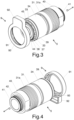
figure 3 shows a first exploded perspective view of a connector of the device offigure 1 ; -
figure 4 shows a second exploded perspective view of a connector of the device offigure 1 ; -
figure 5 shows a partially sectioned side view of the connector offigure 3 ; -
figure 6 shows a bottom view of an embodiment of the tool for mounting and/or removing the connector offigure 3 ; -
figure 7 shows a partially sectioned side view of the tool offigure 6 ; -
figure 8 shows a top view of the tool offigure 6 ; -
figure 9 shows a partially sectioned side view of the connector offigure 3 coupled with the tool offigure 6 ; -
figure 10 shows a partially sectioned side view of the multi-connector device offigure 1 during the mounting of the connector offigure 3 with the tool offigure 6 ; -
figure 11 shows a partially sectioned side view of the device offigure 1 during the coupling with a single male connector. - As shown in
figure 1 , an embodiment of themulti-connector device 1 comprises at least onemain body 2 provided with one or more seats suitable for housing at least partially, in particular completely, at least oneconnector 3. Theconnectors 3 housed in the seats of themain body 2 are arranged with the longitudinal axes substantially parallel to each other and are provided with at least one opening accessible from at least onecoupling side 2a (upper side in the figure) of themain body 2. The seats of themain body 2 for theconnectors 3 open therefore at least towards thecoupling side 2a. Thecoupling side 2a preferably has a surface which is substantially flat and/or substantially perpendicular to the longitudinal axes (vertical in the figure) of theconnectors 3, so that the mouth of theconnectors 3 is substantially flush with this surface. Themain body 2 of themulti-connector device 1 can be connected in a fixed or removable way to a vehicle or another machine. When theconnectors 3 are not coupled with complementary connectors, thecoupling side 2a can be covered by acover 4 which is pivoted to themain body 2. One ormore cams 5 can be pivoted on one or more sides of themain body 2 and can comprise at least oneeccentric groove 6 with anopen end 6a. Thecams 5 are connected to each other, for example by at least onebar 7 which can be provided with ahandle 8, to rotate together between a locked position (shown in the figure) and an unlocked position (rotated about 90° in the direction of the arrow) of themulti-connector device 1. Themain body 2 can also comprise seats for one or more disconnection means 9, in particular pushers, which can be housed in the main body 2 (as in the figure) and can extend from thecoupling side 2a of themain body 2 when aconnector 3 is coupled with a single complementary connector. Themain body 2 can also comprise one ormore cavities 10 which are open towards thecoupling side 2a and extend along an axis substantially parallel to the longitudinal axes of theconnectors 3. -
Figure 2 shows a secondmulti-connector device 11 which is suitable to be coupled with themulti-connector device 1 and which comprises at least onemain body 12 provided with one or more seats suitable for housing at least partially one ormore connectors 13 complementary to theconnectors 3, so that one or more pairs ofconnectors multi-connector devices connectors 13 are arranged with the longitudinal axes (vertical in the figure) substantially parallel to each other and can protrude from acoupling side 12a (lower side in the figure) of themain body 12. Thecoupling side 12a preferably has a surface which is substantially flat and/or substantially perpendicular to the longitudinal axes of theconnectors 13. Themain body 12 of themulti-connector device 11 can be connected in a fixed or removable way to a utility to be connected to said vehicle or machine. One ormore followers 14 can protrude from one or more sides of themain body 12 to enter through theopen end 6a of theeccentric grooves 6 of thecams 5 of themulti-connector device 1 and slide along these grooves, so that by rotating thehandle 8 of themulti-connector device 1 from the unlocked position to the locked position, themulti-connector device 11 is pulled by thecams 5 and by thefollowers 14 to obtain the mutual approach of the twocoupling sides main bodies connectors 13 of themulti-connector device 11 with thecorresponding connectors 3 of themulti-connector device 1, and vice versa by rotating thehandle 8 in the opposite direction. One ormore pins 15 can protrude from thecoupling side 12a of themain body 12 of themulti-connector device 11 to enter thecavities 10 of themain body 1 of themulti-connector device 1, so as to guide the coupling and uncoupling movements (indicated by the arrows) of themulti-connector device 11 with themulti-connector device 1. - The
connectors 3 are provided with connection means necessary to allow the coupling with single connectors. In particular, at least one of theconnectors 3 is a female connector with a flat-faced mouth which can be opened when the mouth of amale connector 13 is inserted into the mouth of the female connector. - As shown in
figures 3-5 , at least oneconnector 3 of themulti-connector device 1 comprises at least onetubular body 31, in particular having a substantially cylindrical symmetry with respect to a longitudinal axis (vertical infigure 3 ) of theconnector 3. Thetubular body 31 can be formed by one or more parts joined together, in particular joined in a coaxial manner. Thetubular body 31 can be provided with a series ofradial openings 32 which partially house a plurality ofspheres 33, for example twelve in number, arranged along a circumference of thetubular body 31. At least onering 34, in particular having a substantially cylindrical symmetry with respect to a longitudinal axis of theconnector 3, can be arranged around thetubular body 31 to cooperate with thespheres 33 and be urged axially by at least onespring 35 which acts between thering 34 and thetubular body 31. Thespheres 33 in theradial openings 32 of thetubular body 31 can move in a radial direction between an extended position (shown in the figure), in which they protrude outside thetubular body 31, and a retracted position, in which they protrude towards the inside of thetubular body 31 The radial movement of thespheres 33 in theradial openings 32 therefore depends on the position of thering 34, and vice versa. In particular, the upper edge of thering 34 can be freed by the movement of thespheres 33 towards the inside of thetubular body 31 or thering 34 can allow thespheres 33 to move towards the outside of thetubular body 31 if thering 34 is pressed against the thrust of thespring 35. Thetubular body 31, thespheres 33 and thering 34 with thespring 35 belong to connection means which allow theconnector 3 to be connected and to stably hold also a single connector, i.e. a connector not mounted on a multi-connector device. At least oneannular relief 37 can be arranged around themouth 38 of thetubular body 31 to prevent thering 34 from separating from thetubular body 31. - At least one
thread 31a is formed around thetubular body 31 of theconnector 3 and is open from the side opposite themouth 38 of theconnector 3, so that theconnector 3 can be screwed into a corresponding threaded seat in a direction D facing the side opposite themouth 38. - The disconnection means 9 of the
connector 3 can comprise a pusher provided with anannular body 91 joined to aradial protuberance 92. Theannular body 91 is joined in a rotatable manner around thering 34, so that the disconnection means 9 are axially fastened to thering 34 but can rotate with respect to it around its longitudinal axis. For this purpose, theannular body 91 is provided with at least oneprotuberance 93 arranged in at least oneannular groove 39 of thering 34, as in the present embodiment, or vice versa. - At least one
fitting 40 can be joined to thetubular body 31 from the side opposite themouth 38 of theconnector 3, so that thetubular body 31 is arranged between themouth 38 and the fitting 40. In particular, thefitting 40 is screwed by means of an external thread in a corresponding internal thread of thetubular body 31, or vice versa. The fitting 40 comprises at least onemouth 41, preferably provided with at least oneannular gasket 42, suitable to be coupled with the mouth of an external duct (not shown in the figures) of a hydraulic line. The fitting 40 is entirely contained in an ideal cylinder having a diameter C equal to the external diameter of thethread 31a. - The coupling means of the
connector 3 can also comprise acoupling mechanism 43, for example of a known type as in the present embodiment, which is arranged in thetubular body 31 and which helps to achieve the coupling between theconnectors mouth 38 by means ofmovable shutters connector 3 together with themouth 38 and the disconnection means 9, if present. - As shown in
figures 6-8 , an embodiment of thetool 50 comprises ahead 51 suitable to be mechanically coupled with a utensil to impart a torque to thetool 50. Thehead 51 in particular has a prismatic shape, for example with a substantially regular hexagonal section, in order to be mechanically coupled with a torque wrench. Thehead 51 of thetool 50 is mechanically connected, for example by means of acollar 52, to ashank 53 substantially coaxial with thehead 51 and/or with thecollar 52. Theshank 53 is suitable to penetrate at least partially into themouth 38 of theconnector 3 in a substantially coaxial manner with respect to thetubular body 31. Thehead 51, thecollar 52 and theshank 53 are preferably made in a single piece, for example of metal. A plurality ofradial seats 54, for example twelve in number, which are arranged along a circumference and are suitable to partially house a corresponding plurality of spheres, in particular thespheres 33 of theconnector 3, are made outside theshank 53. Preferably, thecollar 52 protrudes radially with respect to theshank 53 and/or theshank 53 has a substantially cylindrical shape and/or theradial seats 54 have a concave shape, for example of a spherical, cylindrical or conical cap. At least theshank 53 of thetool 50, in particular theshank 53, thecollar 52 and a portion of thehead 51, preferably has anaxial cavity 55 suitable to house at least partially parts of theconnector 3, in particular parts of thecoupling mechanism 43, such as themovable shutter 44. - As shown in
figure 9 , in a first step of mounting theconnector 3 into themulti-connector device 1, theshank 53 of thetool 50 is inserted into themouth 38 of theconnector 3 until thecollar 52 comes into contact with themouth 38. The distance between thecollar 52 and theradial seats 54 of theshank 53 of thetool 50 is substantially equal to the distance of thespheres 33 from themouth 38 of theconnector 3, so that thespheres 33 penetrate into theradial seats 54 if they are already aligned with each other or if thetool 50 is rotated about its longitudinal axis. When thespheres 33 of theconnector 3 protrude into theradial seats 54 of thetool 50, thering 34 is released and pushed by thespring 35 towards themouth 38 in the direction of the arrow together with the disconnection means 9, so that thetool 50 remains fixed in theconnector 3, with thespheres 33 and thering 34 preventing relative axial or rotational movements of thetool 50 with respect to theconnector 3. Thecoupling mechanism 43 of theconnector 3 is partially arranged in theaxial cavity 55 of thetool 50. The free end of thestem 53 presses themovable shutter 45, moving it away from themouth 38. - As shown in
figure 10 , in a second step of mounting theconnector 3 in themulti-connector device 1, theconnector 3 is inserted in the direction D from thecoupling side 2a into theseat 2b of themain body 2 of themulti-connector device 1 and screwed into theseat 2b in the direction of the arrow in the figure. For this purpose, at least oneseat 2b of themain body 2 is provided with athread 2c, as in the present embodiment, or with an element with a thread, which thread is open towards thecoupling side 2a and is complementary to thethread 31a of thetubular body 31 of theconnector 3. During the insertion of theconnector 3 in theseat 2b of themain body 2, the disconnection means 9 are joined to theconnector 3 and enter at least oneseat 2d which is obtained in thecoupling side 2a of themain body 2 around theseat 2b forconnector 3. Theseat 2d for the disconnection means 9 preferably has an internal profile substantially complementary to the external profile of the disconnection means 9, so that, while theconnector 3 is screwed, thering 34 rotates with respect to the disconnection means 9, which slide axially in theseat 2d without rotating. During the insertion of theconnector 3 into the seat of themain body 2, themouth 41 of the fitting 40 is coupled with themouth 2e of a duct which is obtained in theseat 2b of themain body 2, or is fixed to the latter, from the side opposite thecoupling side 2a to create a hydraulic line with theconnector 3. When theconnector 3 is screwed into theseat 2b, thetool 50 can be disconnected from theconnector 3 by activating the disconnection means 9, in particular by pressing theradial protuberance 92 into theseat 2d of themain body 2, so that thering 34 is pushed towards thetubular body 31 and thespheres 33 can be radially removed from theradial seats 54 of thetool 50, by pulling thetool 50 towards the outside. - As shown in
figure 11 , after theconnector 3 is fixed in themulti-connector device 1, acomplementary connector 80, for example a single male connector according to ISO 16028, can be coupled with theconnector 3 in the direction D from thecoupling side 2a in theseat 2b of themain body 2, until thespheres 33 of theconnector 3 snap into anannular groove 81 of thecomplementary connector 80, so that the latter is axially locked with respect to theconnector 3 but can rotate coaxially with respect to the latter. - The disconnection means 9 can then be operated to release the
complementary connector 80. - When the
multi-connector device 1 is instead coupled with a complementary multi-connector device, in particular themulti-connector device 11, the connectors of this multi-connector device can be without an annular groove, since the fixing between the twomulti-connector devices cams 5 and thefollowers 14 or other fastening mechanisms, whereby the disconnection means 9 of theconnectors 3 remain in theirseats 2d of themain body 2 of themulti-connector device 1 . - Variations or additions can be made by those skilled in the art to the embodiments described and illustrated here, remaining within the scope of the following claims.
Claims (11)
- Connector (3) comprising at least one tubular body (31) provided with at least one mouth (38) suitable to be coupled with a complementary connector (13, 80), wherein the tubular body (31) is also provided with a series of radial openings (32) which partially house a plurality of spheres (33) arranged along a circumference of the tubular body (31), wherein the spheres (33) cooperate with connection means (34, 35) to move in a radial direction of the tubular body (31) between an extended position, in which they protrude towards the outside of the tubular body (31), and a retracted position, in which they protrude towards the inside of the tubular body (31), wherein a thread (31a) is formed around the tubular body (31) or around an element integral with the tubular body (31), wherein the thread (31a) is open from the side opposite the mouth (38) of the connector (3), so that the connector (3) can be screwed into a corresponding threaded seat in a direction (D) facing the side opposite the mouth (38), wherein said connection means (34, 35) comprise at least one ring (34) arranged around the tubular body (31) to cooperate with the spheres (33) and be urged axially by at least one spring (35) which acts between the ring (34) and the tubular body (31), characterized in that disconnection means (9) are axially fastened to the ring (34) and can rotate with respect to the ring (34) around its longitudinal axis.
- Connector (3) according to the preceding claim, wherein said disconnection means (9) comprise a pusher provided with an annular body (91) joined to a radial protuberance (92), wherein the annular body (91) is joined to the ring (34) in a rotatable manner around the ring (34).
- Connector (3) according to the preceding claim, wherein the annular body (91) is provided with at least one protuberance (93) arranged in at least one annular groove (39) of the ring (34), or vice versa.
- Connector (3) according to one of the preceding claims, wherein at least one fitting (40) comprising at least one mouth (41) of the fitting (40) is joined to the tubular body (31) from the side opposite the mouth (38) of the tubular body (31) and is entirely contained in an ideal cylinder having a diameter (C) equal to the external diameter of the thread (31a) of the tubular body (31).
- Connector (3) according to one of the preceding claims, wherein the connector is a female connector with a flat-faced mouth.
- Tool (50) suitable to mount and/or remove a connector (3) according to any preceding claim, respectively into and/or from a multi-connector device (2), wherein this connector (3) comprises at least one tubular body (31) provided with at least one mouth (38) suitable to be coupled with a complementary connector (13, 80), wherein the tubular body (31) is also provided with a series of radial openings (32) which partially house a plurality of spheres (33) arranged along a circumference of the tubular body (31), wherein the spheres (33) cooperate with connecting means (34, 35) to move in a radial direction of the tubular body (31) between an extended position, in which they protrude towards the outside of the tubular body (31), and a retracted position, wherein they protrude towards the inside of the tubular body (31), wherein a thread (31a) is formed around the tubular body (31) or around an element integral with the tubular body (31), wherein the thread (31a) is open from the side opposite the mouth (38) of the connector (3), so that the connector (3) can be screwed into a corresponding threaded seat in a direction (D) facing the side opposite the mouth (38), wherein the tool (50) comprises a head (51) which is suitable to be mechanically coupled with a utensil to impart torque to the tool (50) and which is mechanically connected to a shank (53), wherein a plurality of radial seats (54) are obtained on the outside of the shank (53) and are arranged along a circumference, to partially house said plurality of spheres (33) of the connector (3), so as to couple the tool (50) with the connector (3) to transmit said torque to the connector (3).
- Tool (50) according to the preceding claim, wherein the head (51) is mechanically connected to the shank (53) by means of a collar (52) which protrudes radially with respect to the shank (53).
- Tool (50) according to claim 6 or 7, wherein at least the shank (53) has an axial cavity (55).
- Multi-connector device (1) comprising at least one connector (3) according to one of the claims 1 to 5, the multi-connector device (1) further comprising at least one main body (2) provided with at least one coupling side (2a) and one or more seats (2b) suitable for at least partially housing the at least one connector (3), wherein at least one seat (2b) of the main body (2) is provided with a thread (2c) or an element with a thread, which thread is open towards the coupling side (2a), so that the connector (3) can be inserted from the coupling side (2a) into the seat (2b) of the main body (2) and screwed into this seat (2b).
- Multi-connector device (1) according to the preceding claim, wherein the mouth (2e) of a duct is arranged in the seat (2b) for the connector (3) on the side opposite the coupling side (2a) for making a hydraulic line with the connector (3) arranged in this seat (2b).
- Multi-connector device (1) according to claim 9 or 10, wherein at least one seat (2d) for the disconnection means (9) of the connector (3) is formed in the coupling side (2a) of the main body (2) around the seat (2b) for the connector (3).
Applications Claiming Priority (2)
| Application Number | Priority Date | Filing Date | Title |
|---|---|---|---|
| IT102021000011777A IT202100011777A1 (en) | 2021-05-07 | 2021-05-07 | PLUG FOR HYDRAULIC LINES, MULTI-PLUG DEVICE FOR THIS PLUG AND TOOL FOR FITTING AND/OR REMOVING THE PLUG |
| PCT/IB2022/054197 WO2022234529A1 (en) | 2021-05-07 | 2022-05-06 | Connector for hydraulic lines, multi-connector device for this connector and tool for mounting and/or dismounting the connector |
Publications (2)
| Publication Number | Publication Date |
|---|---|
| EP4334625A1 EP4334625A1 (en) | 2024-03-13 |
| EP4334625B1 true EP4334625B1 (en) | 2025-01-29 |
Family
ID=77412025
Family Applications (1)
| Application Number | Title | Priority Date | Filing Date |
|---|---|---|---|
| EP22726298.7A Active EP4334625B1 (en) | 2021-05-07 | 2022-05-06 | Connector for hydraulic lines, multi-connector device for this connector and tool for mounting and/or dismounting the connector |
Country Status (5)
| Country | Link |
|---|---|
| US (1) | US12455033B2 (en) |
| EP (1) | EP4334625B1 (en) |
| CN (1) | CN117425794A (en) |
| IT (1) | IT202100011777A1 (en) |
| WO (1) | WO2022234529A1 (en) |
Family Cites Families (11)
| Publication number | Priority date | Publication date | Assignee | Title |
|---|---|---|---|---|
| US2399515A (en) * | 1943-10-01 | 1946-04-30 | Thompson Prod Inc | Multiple quick disconnect coupling |
| US5996452A (en) * | 1998-10-13 | 1999-12-07 | Chiang; Shu Chi | Chuck device for power tool |
| US6324962B1 (en) * | 2000-04-10 | 2001-12-04 | Crary Company | Valve block mounting arrangement |
| DE10230293A1 (en) * | 2002-07-05 | 2004-06-03 | Dart Engineering Ag | Flat-face valve-controlled hydraulic link fitting for mechanical excavator |
| JP2005121198A (en) * | 2003-10-20 | 2005-05-12 | Honda Motor Co Ltd | Relay device |
| ITMI20120429A1 (en) * | 2012-03-19 | 2013-09-20 | Faster Spa | MULTICONNECTION DEVICE |
| EP2884146B8 (en) | 2013-12-10 | 2017-04-19 | Faster S.p.A. | Multi-connector device for the multiple quick connection of multiple hydraulic, electrical and/or pneumatic lines, with the possibility of individual manual connectors |
| US20170307123A1 (en) * | 2016-04-20 | 2017-10-26 | Hsiu-Hsiung LIU | Connector assembly |
| US10247341B2 (en) * | 2017-08-07 | 2019-04-02 | Hsiu-Hsiung LIU | Quick connect fitting |
| EP3714197B1 (en) * | 2017-11-20 | 2022-01-05 | Parker-Hannifin Corporation | Latch mechanism for multi-coupling |
| US12222058B2 (en) * | 2021-01-04 | 2025-02-11 | Oetiker Ny, Inc. | Tamper resistant fluid connection assembly with visual connection verifier |
-
2021
- 2021-05-07 IT IT102021000011777A patent/IT202100011777A1/en unknown
-
2022
- 2022-05-06 US US18/289,648 patent/US12455033B2/en active Active
- 2022-05-06 CN CN202280033069.7A patent/CN117425794A/en active Pending
- 2022-05-06 WO PCT/IB2022/054197 patent/WO2022234529A1/en not_active Ceased
- 2022-05-06 EP EP22726298.7A patent/EP4334625B1/en active Active
Also Published As
| Publication number | Publication date |
|---|---|
| WO2022234529A1 (en) | 2022-11-10 |
| IT202100011777A1 (en) | 2022-11-07 |
| US12455033B2 (en) | 2025-10-28 |
| US20240255086A1 (en) | 2024-08-01 |
| CN117425794A (en) | 2024-01-19 |
| EP4334625A1 (en) | 2024-03-13 |
Similar Documents
| Publication | Publication Date | Title |
|---|---|---|
| EP3440747B1 (en) | A connection system with a bayonet-type locking device adapted to allow a quick disconnecting operation | |
| EP1666783B1 (en) | Pipe joint and socket for pipe joint | |
| KR102388166B1 (en) | Multi-Line Connections Quick Multi-Coupling | |
| CA2671232C (en) | Locking pin | |
| US5340248A (en) | Mechanical chuck with clamp for pulling tool shank to tightly clamped position | |
| CN110230645B (en) | Quick connecting device | |
| EP3714197B1 (en) | Latch mechanism for multi-coupling | |
| US20220324034A1 (en) | Operating key for stationary and driven tool holders | |
| US4974635A (en) | Coupler with spring-locked valves | |
| US20100200240A1 (en) | Multicoupler | |
| CN209487859U (en) | A kind of fast insert-pull multi-core connector | |
| US12455033B2 (en) | Connector for hydraulic lines, multi-connector device for this connector and tool for mounting and/or dismounting the connector | |
| EP2424048B1 (en) | Connector and connecting device for forming a releasable connection | |
| CN115030946B (en) | Pin-type quick-release expansion device | |
| JP2009289644A (en) | Connector | |
| KR100332307B1 (en) | Connector | |
| CN221041716U (en) | Flat installation quick-locking connector | |
| CN219311773U (en) | Glove production is with mould subassembly mounting structure | |
| CN214380500U (en) | Quick change structure of motor | |
| CN216952148U (en) | Quick-operation joint hasp structure and quick-operation joint thereof | |
| CN213906485U (en) | Motor quick-change structure directly connected and installed | |
| CN213906540U (en) | Motor quick-change structure directly connected and installed | |
| CN112510963B (en) | Direct-drive motor quick-change structure | |
| US6276880B1 (en) | Tool interconnect structure | |
| CN112542917A (en) | Motor quick-change structure directly connected and installed |
Legal Events
| Date | Code | Title | Description |
|---|---|---|---|
| STAA | Information on the status of an ep patent application or granted ep patent |
Free format text: STATUS: UNKNOWN |
|
| STAA | Information on the status of an ep patent application or granted ep patent |
Free format text: STATUS: THE INTERNATIONAL PUBLICATION HAS BEEN MADE |
|
| PUAI | Public reference made under article 153(3) epc to a published international application that has entered the european phase |
Free format text: ORIGINAL CODE: 0009012 |
|
| STAA | Information on the status of an ep patent application or granted ep patent |
Free format text: STATUS: REQUEST FOR EXAMINATION WAS MADE |
|
| 17P | Request for examination filed |
Effective date: 20231127 |
|
| AK | Designated contracting states |
Kind code of ref document: A1 Designated state(s): AL AT BE BG CH CY CZ DE DK EE ES FI FR GB GR HR HU IE IS IT LI LT LU LV MC MK MT NL NO PL PT RO RS SE SI SK SM TR |
|
| P01 | Opt-out of the competence of the unified patent court (upc) registered |
Effective date: 20240315 |
|
| DAV | Request for validation of the european patent (deleted) | ||
| DAX | Request for extension of the european patent (deleted) | ||
| GRAP | Despatch of communication of intention to grant a patent |
Free format text: ORIGINAL CODE: EPIDOSNIGR1 |
|
| STAA | Information on the status of an ep patent application or granted ep patent |
Free format text: STATUS: GRANT OF PATENT IS INTENDED |
|
| INTG | Intention to grant announced |
Effective date: 20240913 |
|
| GRAS | Grant fee paid |
Free format text: ORIGINAL CODE: EPIDOSNIGR3 |
|
| GRAA | (expected) grant |
Free format text: ORIGINAL CODE: 0009210 |
|
| STAA | Information on the status of an ep patent application or granted ep patent |
Free format text: STATUS: THE PATENT HAS BEEN GRANTED |
|
| AK | Designated contracting states |
Kind code of ref document: B1 Designated state(s): AL AT BE BG CH CY CZ DE DK EE ES FI FR GB GR HR HU IE IS IT LI LT LU LV MC MK MT NL NO PL PT RO RS SE SI SK SM TR |
|
| REG | Reference to a national code |
Ref country code: GB Ref legal event code: FG4D |
|
| REG | Reference to a national code |
Ref country code: CH Ref legal event code: EP |
|
| REG | Reference to a national code |
Ref country code: DE Ref legal event code: R096 Ref document number: 602022010215 Country of ref document: DE |
|
| REG | Reference to a national code |
Ref country code: IE Ref legal event code: FG4D |
|
| REG | Reference to a national code |
Ref country code: NL Ref legal event code: MP Effective date: 20250129 |
|
| PG25 | Lapsed in a contracting state [announced via postgrant information from national office to epo] |
Ref country code: NL Free format text: LAPSE BECAUSE OF FAILURE TO SUBMIT A TRANSLATION OF THE DESCRIPTION OR TO PAY THE FEE WITHIN THE PRESCRIBED TIME-LIMIT Effective date: 20250129 |
|
| PG25 | Lapsed in a contracting state [announced via postgrant information from national office to epo] |
Ref country code: RS Free format text: LAPSE BECAUSE OF FAILURE TO SUBMIT A TRANSLATION OF THE DESCRIPTION OR TO PAY THE FEE WITHIN THE PRESCRIBED TIME-LIMIT Effective date: 20250429 |
|
| PG25 | Lapsed in a contracting state [announced via postgrant information from national office to epo] |
Ref country code: FI Free format text: LAPSE BECAUSE OF FAILURE TO SUBMIT A TRANSLATION OF THE DESCRIPTION OR TO PAY THE FEE WITHIN THE PRESCRIBED TIME-LIMIT Effective date: 20250129 |
|
| PG25 | Lapsed in a contracting state [announced via postgrant information from national office to epo] |
Ref country code: PL Free format text: LAPSE BECAUSE OF FAILURE TO SUBMIT A TRANSLATION OF THE DESCRIPTION OR TO PAY THE FEE WITHIN THE PRESCRIBED TIME-LIMIT Effective date: 20250129 |
|
| PGFP | Annual fee paid to national office [announced via postgrant information from national office to epo] |
Ref country code: DE Payment date: 20250528 Year of fee payment: 4 |
|
| PG25 | Lapsed in a contracting state [announced via postgrant information from national office to epo] |
Ref country code: ES Free format text: LAPSE BECAUSE OF FAILURE TO SUBMIT A TRANSLATION OF THE DESCRIPTION OR TO PAY THE FEE WITHIN THE PRESCRIBED TIME-LIMIT Effective date: 20250129 |
|
| REG | Reference to a national code |
Ref country code: LT Ref legal event code: MG9D |
|
| PG25 | Lapsed in a contracting state [announced via postgrant information from national office to epo] |
Ref country code: IS Free format text: LAPSE BECAUSE OF FAILURE TO SUBMIT A TRANSLATION OF THE DESCRIPTION OR TO PAY THE FEE WITHIN THE PRESCRIBED TIME-LIMIT Effective date: 20250529 Ref country code: NO Free format text: LAPSE BECAUSE OF FAILURE TO SUBMIT A TRANSLATION OF THE DESCRIPTION OR TO PAY THE FEE WITHIN THE PRESCRIBED TIME-LIMIT Effective date: 20250429 |
|
| PGFP | Annual fee paid to national office [announced via postgrant information from national office to epo] |
Ref country code: IT Payment date: 20250531 Year of fee payment: 4 |
|
| REG | Reference to a national code |
Ref country code: AT Ref legal event code: MK05 Ref document number: 1763748 Country of ref document: AT Kind code of ref document: T Effective date: 20250129 |
|
| PG25 | Lapsed in a contracting state [announced via postgrant information from national office to epo] |
Ref country code: HR Free format text: LAPSE BECAUSE OF FAILURE TO SUBMIT A TRANSLATION OF THE DESCRIPTION OR TO PAY THE FEE WITHIN THE PRESCRIBED TIME-LIMIT Effective date: 20250129 |
|
| PG25 | Lapsed in a contracting state [announced via postgrant information from national office to epo] |
Ref country code: LV Free format text: LAPSE BECAUSE OF FAILURE TO SUBMIT A TRANSLATION OF THE DESCRIPTION OR TO PAY THE FEE WITHIN THE PRESCRIBED TIME-LIMIT Effective date: 20250129 Ref country code: PT Free format text: LAPSE BECAUSE OF FAILURE TO SUBMIT A TRANSLATION OF THE DESCRIPTION OR TO PAY THE FEE WITHIN THE PRESCRIBED TIME-LIMIT Effective date: 20250529 |
|
| PGFP | Annual fee paid to national office [announced via postgrant information from national office to epo] |
Ref country code: FR Payment date: 20250516 Year of fee payment: 4 |
|
| PG25 | Lapsed in a contracting state [announced via postgrant information from national office to epo] |
Ref country code: BG Free format text: LAPSE BECAUSE OF FAILURE TO SUBMIT A TRANSLATION OF THE DESCRIPTION OR TO PAY THE FEE WITHIN THE PRESCRIBED TIME-LIMIT Effective date: 20250129 Ref country code: GR Free format text: LAPSE BECAUSE OF FAILURE TO SUBMIT A TRANSLATION OF THE DESCRIPTION OR TO PAY THE FEE WITHIN THE PRESCRIBED TIME-LIMIT Effective date: 20250430 |
|
| PG25 | Lapsed in a contracting state [announced via postgrant information from national office to epo] |
Ref country code: AT Free format text: LAPSE BECAUSE OF FAILURE TO SUBMIT A TRANSLATION OF THE DESCRIPTION OR TO PAY THE FEE WITHIN THE PRESCRIBED TIME-LIMIT Effective date: 20250129 |
|
| PG25 | Lapsed in a contracting state [announced via postgrant information from national office to epo] |
Ref country code: SE Free format text: LAPSE BECAUSE OF FAILURE TO SUBMIT A TRANSLATION OF THE DESCRIPTION OR TO PAY THE FEE WITHIN THE PRESCRIBED TIME-LIMIT Effective date: 20250129 |
|
| PG25 | Lapsed in a contracting state [announced via postgrant information from national office to epo] |
Ref country code: SM Free format text: LAPSE BECAUSE OF FAILURE TO SUBMIT A TRANSLATION OF THE DESCRIPTION OR TO PAY THE FEE WITHIN THE PRESCRIBED TIME-LIMIT Effective date: 20250129 |
|
| PG25 | Lapsed in a contracting state [announced via postgrant information from national office to epo] |
Ref country code: DK Free format text: LAPSE BECAUSE OF FAILURE TO SUBMIT A TRANSLATION OF THE DESCRIPTION OR TO PAY THE FEE WITHIN THE PRESCRIBED TIME-LIMIT Effective date: 20250129 |
|
| PG25 | Lapsed in a contracting state [announced via postgrant information from national office to epo] |
Ref country code: EE Free format text: LAPSE BECAUSE OF FAILURE TO SUBMIT A TRANSLATION OF THE DESCRIPTION OR TO PAY THE FEE WITHIN THE PRESCRIBED TIME-LIMIT Effective date: 20250129 Ref country code: CZ Free format text: LAPSE BECAUSE OF FAILURE TO SUBMIT A TRANSLATION OF THE DESCRIPTION OR TO PAY THE FEE WITHIN THE PRESCRIBED TIME-LIMIT Effective date: 20250129 |
|
| PG25 | Lapsed in a contracting state [announced via postgrant information from national office to epo] |
Ref country code: RO Free format text: LAPSE BECAUSE OF FAILURE TO SUBMIT A TRANSLATION OF THE DESCRIPTION OR TO PAY THE FEE WITHIN THE PRESCRIBED TIME-LIMIT Effective date: 20250129 |
|
| PG25 | Lapsed in a contracting state [announced via postgrant information from national office to epo] |
Ref country code: SK Free format text: LAPSE BECAUSE OF FAILURE TO SUBMIT A TRANSLATION OF THE DESCRIPTION OR TO PAY THE FEE WITHIN THE PRESCRIBED TIME-LIMIT Effective date: 20250129 |
|
| REG | Reference to a national code |
Ref country code: DE Ref legal event code: R097 Ref document number: 602022010215 Country of ref document: DE |
|
| PLBE | No opposition filed within time limit |
Free format text: ORIGINAL CODE: 0009261 |
|
| STAA | Information on the status of an ep patent application or granted ep patent |
Free format text: STATUS: NO OPPOSITION FILED WITHIN TIME LIMIT |
|
| REG | Reference to a national code |
Ref country code: CH Ref legal event code: L10 Free format text: ST27 STATUS EVENT CODE: U-0-0-L10-L00 (AS PROVIDED BY THE NATIONAL OFFICE) Effective date: 20251210 |
|
| REG | Reference to a national code |
Ref country code: CH Ref legal event code: H13 Free format text: ST27 STATUS EVENT CODE: U-0-0-H10-H13 (AS PROVIDED BY THE NATIONAL OFFICE) Effective date: 20251223 |
|
| 26N | No opposition filed |
Effective date: 20251030 |
|
| PG25 | Lapsed in a contracting state [announced via postgrant information from national office to epo] |
Ref country code: LU Free format text: LAPSE BECAUSE OF NON-PAYMENT OF DUE FEES Effective date: 20250506 |
|
| PG25 | Lapsed in a contracting state [announced via postgrant information from national office to epo] |
Ref country code: CH Free format text: LAPSE BECAUSE OF NON-PAYMENT OF DUE FEES Effective date: 20250531 |
|
| REG | Reference to a national code |
Ref country code: BE Ref legal event code: MM Effective date: 20250531 |
|
| PG25 | Lapsed in a contracting state [announced via postgrant information from national office to epo] |
Ref country code: MC Free format text: LAPSE BECAUSE OF FAILURE TO SUBMIT A TRANSLATION OF THE DESCRIPTION OR TO PAY THE FEE WITHIN THE PRESCRIBED TIME-LIMIT Effective date: 20250129 |
|
| PG25 | Lapsed in a contracting state [announced via postgrant information from national office to epo] |
Ref country code: IE Free format text: LAPSE BECAUSE OF NON-PAYMENT OF DUE FEES Effective date: 20250506 |
|
| PG25 | Lapsed in a contracting state [announced via postgrant information from national office to epo] |
Ref country code: BE Free format text: LAPSE BECAUSE OF NON-PAYMENT OF DUE FEES Effective date: 20250531 |