EP4334618B1 - Rohrverbindung zur erkundung und herstellung eines kohlenwasserstoffbohrlochs - Google Patents
Rohrverbindung zur erkundung und herstellung eines kohlenwasserstoffbohrlochs Download PDFInfo
- Publication number
- EP4334618B1 EP4334618B1 EP22728136.7A EP22728136A EP4334618B1 EP 4334618 B1 EP4334618 B1 EP 4334618B1 EP 22728136 A EP22728136 A EP 22728136A EP 4334618 B1 EP4334618 B1 EP 4334618B1
- Authority
- EP
- European Patent Office
- Prior art keywords
- primary
- ring
- pipe member
- pipe connection
- locking ring
- Prior art date
- Legal status (The legal status is an assumption and is not a legal conclusion. Google has not performed a legal analysis and makes no representation as to the accuracy of the status listed.)
- Active
Links
Images


Classifications
-
- F—MECHANICAL ENGINEERING; LIGHTING; HEATING; WEAPONS; BLASTING
- F16—ENGINEERING ELEMENTS AND UNITS; GENERAL MEASURES FOR PRODUCING AND MAINTAINING EFFECTIVE FUNCTIONING OF MACHINES OR INSTALLATIONS; THERMAL INSULATION IN GENERAL
- F16L—PIPES; JOINTS OR FITTINGS FOR PIPES; SUPPORTS FOR PIPES, CABLES OR PROTECTIVE TUBING; MEANS FOR THERMAL INSULATION IN GENERAL
- F16L37/00—Couplings of the quick-acting type
- F16L37/08—Couplings of the quick-acting type in which the connection between abutting or axially overlapping ends is maintained by locking members
- F16L37/084—Couplings of the quick-acting type in which the connection between abutting or axially overlapping ends is maintained by locking members combined with automatic locking
- F16L37/098—Couplings of the quick-acting type in which the connection between abutting or axially overlapping ends is maintained by locking members combined with automatic locking by means of flexible hooks
- F16L37/0985—Couplings of the quick-acting type in which the connection between abutting or axially overlapping ends is maintained by locking members combined with automatic locking by means of flexible hooks the flexible hook extending radially inwardly from an outer part and engaging a bead, recess or the like on an inner part
-
- E—FIXED CONSTRUCTIONS
- E21—EARTH OR ROCK DRILLING; MINING
- E21B—EARTH OR ROCK DRILLING; OBTAINING OIL, GAS, WATER, SOLUBLE OR MELTABLE MATERIALS OR A SLURRY OF MINERALS FROM WELLS
- E21B17/00—Drilling rods or pipes; Flexible drill strings; Kellies; Drill collars; Sucker rods; Cables; Casings; Tubings
- E21B17/02—Couplings; joints
- E21B17/04—Couplings; joints between rod or the like and bit or between rod and rod or the like
- E21B17/046—Couplings; joints between rod or the like and bit or between rod and rod or the like with ribs, pins, or jaws, and complementary grooves or the like, e.g. bayonet catches
-
- F—MECHANICAL ENGINEERING; LIGHTING; HEATING; WEAPONS; BLASTING
- F16—ENGINEERING ELEMENTS AND UNITS; GENERAL MEASURES FOR PRODUCING AND MAINTAINING EFFECTIVE FUNCTIONING OF MACHINES OR INSTALLATIONS; THERMAL INSULATION IN GENERAL
- F16L—PIPES; JOINTS OR FITTINGS FOR PIPES; SUPPORTS FOR PIPES, CABLES OR PROTECTIVE TUBING; MEANS FOR THERMAL INSULATION IN GENERAL
- F16L37/00—Couplings of the quick-acting type
- F16L37/08—Couplings of the quick-acting type in which the connection between abutting or axially overlapping ends is maintained by locking members
- F16L37/084—Couplings of the quick-acting type in which the connection between abutting or axially overlapping ends is maintained by locking members combined with automatic locking
- F16L37/088—Couplings of the quick-acting type in which the connection between abutting or axially overlapping ends is maintained by locking members combined with automatic locking by means of a split elastic ring
-
- F—MECHANICAL ENGINEERING; LIGHTING; HEATING; WEAPONS; BLASTING
- F16—ENGINEERING ELEMENTS AND UNITS; GENERAL MEASURES FOR PRODUCING AND MAINTAINING EFFECTIVE FUNCTIONING OF MACHINES OR INSTALLATIONS; THERMAL INSULATION IN GENERAL
- F16L—PIPES; JOINTS OR FITTINGS FOR PIPES; SUPPORTS FOR PIPES, CABLES OR PROTECTIVE TUBING; MEANS FOR THERMAL INSULATION IN GENERAL
- F16L37/00—Couplings of the quick-acting type
- F16L37/08—Couplings of the quick-acting type in which the connection between abutting or axially overlapping ends is maintained by locking members
- F16L37/12—Couplings of the quick-acting type in which the connection between abutting or axially overlapping ends is maintained by locking members using hooks, pawls, or other movable or insertable locking members
- F16L37/1225—Couplings of the quick-acting type in which the connection between abutting or axially overlapping ends is maintained by locking members using hooks, pawls, or other movable or insertable locking members using a retaining member the extremities of which, e.g. in the form of a U, engage behind a shoulder of both parts
Definitions
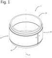
- the invention relates to a pipe connection for exploration and production of a hydrocarbon well.
- the pipe connection comprises a primary pipe member, a secondary pipe member and a locking ring engaging the primary pipe member and the secondary pipe member.
- the primary pipe member comprises a primary alignment sleeve and one of a first protrusion and a first slot. Said one of the first protrusion and the first slot is provided at a primary circumferential surface of the primary pipe member.
- the secondary pipe member comprises a secondary alignment sleeve and one of a second protrusion and a second slot. Said one of the second protrusion and the second slot is provided at a secondary circumferential surface of the secondary pipe member.
- the locking ring is resilient in radial direction and comprises a primary ring part having the other of the first protrusion and the first slot, a secondary ring part having the other of the second protrusion and the second slot, and a ring circumferential surface defining a ring diameter. Said other of the first protrusion and the first slot and said other of the second protrusion and the second slot are provided at the ring circumferential surface of the locking ring and located at an axial ring distance from each other.
- the locking ring is configured to engage the primary pipe member with the primary ring part by having said one of the first protrusion and the first slot of the primary pipe member engaged with said other of the first protrusion and the first slot of the locking ring.
- the locking ring is configured to engage the secondary pipe member with the secondary ring part by having said one of the second protrusion and the second slot of the secondary pipe member engaged with said other of the second protrusion and the second slot of the locking ring.
- US4547003 discloses a pipe connector comprising a split annular ring for surrounding and engaging the end portions of two pipes.
- the ring has a generally U-shaped radial section providing arms having inwardly extending transverse surfaces directed towards each other and which, when the ring is engaged on the pipe ends, engage outwardly extending transverse surfaces on the pipe ends.
- the ring is permanently engaged with one pipe and is resiliently expandable to permit engagement of the other pipe therewith, corresponding surface portions of the pipe end portion and ring being shaped so that the ring is automatically expanded as the other pipe end portion is engaged therewith.
- Centering and guiding means comprising a cylindrical extension on the one pipe which is received within the other pipe are provided for maintaining coaxiality between the pipes as they are brought together and the other pipe is engaged with the ring.
- This type of pipe connection is often used for conductor pipe strings, but may also be used for other types of pipe strings for exploration and production of a hydrocarbon well, such as for forming a landing string.
- the locking ring is used to connect the primary pipe member and the secondary pipe member to each other.
- the known pipe connections have the disadvantage that there is a relatively high risk that the locking ring is not correctly engaged with the secondary pipe member after make-up is finished. More specifically, said one of the second protrusion and the second slot of the secondary pipe member is not correctly engaged with said other of the second protrusion and the second slot of the locking ring. This makes the pipe connection less reliable. Preventing incorrect engagement of the locking ring with the secondary pipe member is relevant because repairing an incorrect connected pipe connection is time consuming and if not repaired it may lead to failure of the pipe string during exploration and production of a hydrocarbon well.
- the invention has the objective to provide an improved, or at least alternative, pipe connection for exploration and production of a hydrocarbon well.
- Said pipe connection comprises:
- the locking ring is first attached to the primary pipe member. Attaching the locking ring to the primary pipe member can be performed at the mill where the primary pipe member, the secondary pipe member and the locking ring are produced, or can be performed outside the mill at a different location.
- the locking ring being engaged with the primary pipe member is during make-up of the pipe connection (at the hydrocarbon well) moved in axial direction towards the secondary pipe member in order to attach the locking ring to the secondary pipe member.
- Final make-up of the pipe connection is reached when the locking ring engages the primary pipe member and the secondary pipe member.
- the overlapping primary alignment sleeve and the secondary alignment sleeve align the primary pipe member and the secondary pipe member during said make-up of the pipe connection in which the locking ring being engaged with the primary pipe member is moved in axial direction towards the secondary pipe member.
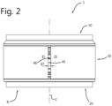
- the locking ring engages the primary pipe member and the secondary pipe member, and the primary pipe member, secondary pipe member and the locking ring extend along a longitudinal axis.
- the used terms “axial” and “radial” relate to said longitudinal axis.
- the primary alignment sleeve comprises a primary pipe end of the primary pipe member
- the secondary alignment sleeve comprises a secondary pipe end of the secondary pipe member
- the primary pipe end is in axial direction positioned beyond the secondary pipe end when the primary pipe member and the secondary pipe member overlap each other.
- area may refer to a section of a surface of a body.
- said first axial distance and said second axial distance overlap in axial direction.
- said second axial distance overlaps said first axial distance completely in axial direction.
- an internal surface may face towards the longitudinal axis, and an external surface may face away from the longitudinal axis.
- the secondary alignment sleeve is located closer to the longitudinal axis than the primary alignment sleeve.
- the primary alignment sleeve is in radial direction at final make-up located between the secondary alignment sleeve and the locking ring.
- the primary alignment sleeve is located closer to the secondary alignment sleeve than the locking ring.
- the primary alignment sleeve may be located closer to the secondary alignment sleeve than the ring circumferential surface defining the ring diameter. Even more in particular, the primary alignment sleeve may be located closer to the secondary alignment sleeve than the ring internal circumferential surface.
- the adjustment portion is formed as not being part of the secondary alignment sleeve.
- the adjustment portion may be provided at the secondary shoulder.
- the primary nose is at final make-up adjacent to the secondary shoulder, and the primary shoulder is at final make-up adjacent to the secondary nose.
- the primary retainer surface and the secondary retainer surface are configured to have a third clearance between each other at final make-up of the pipe connection.
- the primary retainer surface and the secondary retainer surface are configured to be in contact with each other at final make-up of the pipe connection.
- the primary retainer surface extends (in radial direction away from the longitudinal axis) towards said one of the first protrusion and the first slot
- the secondary retainer surface extends (in radial direction away from the longitudinal axis) away from said one of the second protrusion and the second slot.
- the primary shoulder surface and the secondary nose surface may be aligned.
- the primary shoulder surface extends (in radial direction away from the longitudinal axis) towards said one of the first protrusion and the first slot
- the secondary nose surface extends in (in radial direction away from the longitudinal axis) away from said one of the second protrusion and the second slot.
- the primary alignment sleeve and/or the secondary alignment sleeve comprise a groove to accommodate the elastomeric seal.
- the elastomeric seal is in axial direction at final make-up located closer to the primary shoulder than to the secondary shoulder.
- the pipe connection 1 is configured for exploration and production of a hydrocarbon well. This type of pipe connection 1 is often used for conductor pipe strings, but may also be used for other types of pipe strings for exploration and production of a hydrocarbon well, such as for a landing string.
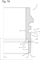
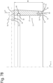
- the primary pipe member 10 comprises an axially extending primary alignment sleeve 11 and a first slot 13.
- the first slot 13 is provided at a primary circumferential surface 14 of the primary pipe member 10.
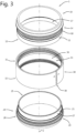
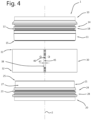
- the primary pipe member 10 is depicted in the figures 3 and 4 showing the pipe connection 1 before make-up.
- the figures 7A and 7B show the primary pipe member 10 in a cross sectional view along the longitudinal axis 2.
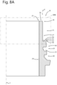
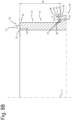
- the secondary pipe member 20 comprises an axially extending secondary alignment sleeve 21 and a second slot 23.
- the second slot 23 is provided at a secondary circumferential surface 24 of the secondary pipe member 20.
- the secondary pipe member 20 is depicted in the figures 3 and 4 showing the pipe connection 1 before make-up.
- the figures 8A and 8B show the secondary pipe member 20 in a cross sectional view along the longitudinal axis 2.
- the locking ring 30 is configured to engage the primary pipe member 10 with the primary ring part 31 by having the first protrusion 12 of the locking ring 30 engaged with the first slot 13 of the primary pipe member 10 (see figure 15A ).
- the primary pipe member comprises a first protrusion
- the locking ring comprises a first slot
- the locking ring is configured to engage the primary pipe member with the primary ring part by having the first protrusion of the primary pipe member engaged with the first slot of the locking ring.
- the circular cross section of the locking ring 30 starts at a first end 45, and ends at an opposite second end 46, wherein the first end 45 and the second end 46 face each other.
- the first end 45 and the second end 46 define the opening 38 between said first and second ends 45, 46. More in particular, the first end 45 and the second end 46 are located at a ring circumferential distance 47 of between, and including, 10 mm to 30 mm, even more in particular between, and including, 15 mm to 25 mm, from each other.
- the locking ring 30 being engaged with the primary pipe member 10 is during make-up moved in axial direction towards the secondary pipe member 20 in order to attach the locking ring 30 to the secondary pipe member 20.
- the figures 5 and 6 show the situation in which the locking ring 30 is engaged with the primary pipe member 10 and positioned above the secondary pipe member 20.
- the engaged primary pipe member 10 and locking ring 30 will be moved in the axial direction indicated by arrow 3 toward the secondary pipe member 20. This is depicted in the figures 10-14 showing the pipe connection 1 in cross sectional views along the longitudinal axis 2.
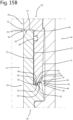
- the engaged primary pipe member 10 and locking ring 30 are moved further in the axial direction of arrow 3 when compared with figure 14 and final make-up 8 of the pipe connection 1 has been reached.
- the locking ring 30 engages the primary pipe member 10 and the secondary pipe member 20.
- the second protrusion 22 of the locking ring 30 engages with the second slot 23 of the secondary pipe member 20.
- the ring diameter of the locking ring 30 is back to D1.
- the overlapping primary alignment sleeve 11 and the secondary alignment sleeve 21 align the primary pipe member 10 and the secondary pipe member 20 during the make-up of the pipe connection 1.
- the pipe connection 1 tends to have a reduced risk of creating damage to the secondary pipe member 20, more specifically the adjustment portion 40, and/or the locking ring 30 during make-up. Said damage reduces the number of times that the pipe connection 1 can be disconnected and re-used.
- the primary alignment sleeve 11 comprises a primary pipe end 15 of the primary pipe member 10.
- the secondary alignment sleeve 21 comprises a secondary pipe end 25 of the secondary pipe member 20.
- the primary pipe end 15 is in axial direction positioned beyond the secondary pipe end 25 when the primary pipe member 10 and the secondary pipe member 20 overlap each other (see the figures 11-15 ).
- the secondary alignment sleeve 21 comprises a first overlap secondary sleeve area 26 which overlaps as first the primary alignment sleeve 11, more specifically the first overlap primary sleeve area 16, during said make-up of the pipe connection 1.
- a first axial distance 5 between the first contact ring area 35 and the first overlap primary sleeve area 16 of the locking ring 30 being engaged to the primary pipe member 10 is shorter than a second axial distance 6 between the first contact portion area 41 and the first overlap secondary sleeve area 26 (see figure 11 and 12 ).
- the used term "area" refers to a section of a surface of a body.
- the first contact ring area 35 of the locking ring 30 refers to the section of the ring internal circumferential surface 36 configured to make first contact with the adjustment portion 40 of the secondary pipe member 20.
- the primary circumferential surface of the primary pipe member is a primary internal circumferential surface.
- the secondary circumferential surface of the primary pipe member is a secondary internal circumferential surface.
- the ring circumferential surface of the locking ring 30 is a ring external circumferential surface.
- the adjustment portion is an internal adjustment portion configured to decrease the ring diameter of the secondary ring part of the locking ring.
- the primary pipe member comprises a primary external circumferential surface.
- the secondary pipe member comprises a secondary external circumferential surface.
- the primary external circumferential surface and the secondary external circumferential surface are flush with each other.
- the pipe connection is free from any items provided at the primary external circumferential surface and the secondary external circumferential surface forming an obstruction in axial direction. This way it ensured that no obstructions are provided to lower the pipe connection into the hydrocarbon well.
- the primary shoulder 53 comprises a primary shoulder surface 54 extending under an angle ⁇ of between, and including, 80 degrees and 90 degrees, preferably between, and including, 85 degrees and 90 degrees, relative to the longitudinal axis 2.
- the secondary nose 56 comprises a secondary nose surface 57 extending under an angle ⁇ of between, and including, 80 degrees and 90 degrees, preferably between, and including, 85 degrees and 90 degrees, relative to the longitudinal axis 2.
- the primary shoulder surface 54 and the secondary nose surface 57 are configured to be in contact with each other at final make-up 8 of the pipe connection 1.
- the primary shoulder surface 54 and the secondary nose surface 57 are aligned.
- the primary shoulder surface 54 extends in (in radial direction away from the longitudinal axis) towards the first slot 13.
- the secondary nose surface 57 extends in radial direction away from the second slot 23.
- the secondary alignment sleeve is in radial direction at final make-up located between the primary alignment sleeve and the locking ring, and the secondary alignment sleeve is spaced in said radial direction from the locking ring.
- a space is provided between the secondary alignment sleeve and the locking ring.
- the secondary nose may be spaced in said radial direction from the locking ring.
- the first protrusion 12 and the first slot 13 are configured to receive the first protrusion 12 in the first slot 13 at final make-up 8 over a first radial engagement distance 71 relative to the longitudinal axis 2.
- the second protrusion 22 and second slot 23 are configured to receive the second protrusion 22 in the second slot 23 at final make-up 8 over a second radial engagement distance 72 relative to the longitudinal axis 2.
- the first radial engagement distance 71 is larger than the second radial engagement distance 72 (see figure 15A ).
- the overlap in radial direction between the first protrusion 12 in the first slot 13 is larger than the overlap in radial direction between the second protrusion 22 and second slot 23. This facilitates that the locking ring 30 remains engaged with the primary pipe member 10 due to the fact that part of the first protrusion 12 remains located in the first slot 13 when the ring diameter is adjusted during make-up (see figure 14 ).
Landscapes
- Engineering & Computer Science (AREA)
- General Engineering & Computer Science (AREA)
- Mechanical Engineering (AREA)
- Life Sciences & Earth Sciences (AREA)
- Geology (AREA)
- Mining & Mineral Resources (AREA)
- Physics & Mathematics (AREA)
- Environmental & Geological Engineering (AREA)
- Fluid Mechanics (AREA)
- General Life Sciences & Earth Sciences (AREA)
- Geochemistry & Mineralogy (AREA)
- Quick-Acting Or Multi-Walled Pipe Joints (AREA)
Claims (14)
- Rohrverbindung (1) zur Exploration und Herstellung eines Kohlenwasserstoffbohrlochs, wobei die Rohrverbindung Folgendes umfasst:- ein primäres Rohrelement (10), das eine sich axial erstreckende primäre Ausrichtungshülse (11) und einen eines ersten Vorsprungs (12) und eines ersten Schlitzes (13) umfasst, wobei der eine des ersten Vorsprungs und des ersten Schlitzes an einer primären Umfangsfläche (14) des primären Rohrelements bereitgestellt ist,- ein sekundäres Rohrelement (20), das eine sich axial erstreckende sekundäre Ausrichtungshülse (21) und einen eines zweiten Vorsprungs (22) und eines zweiten Schlitzes (23) umfasst, wobei der eine des zweiten Vorsprungs und des zweiten Schlitzes an einer sekundären Umfangsfläche (24) des sekundären Rohrelements bereitgestellt ist, und- einen Sicherungsring (30), der in radialer Richtung nachgiebig ist und einen primären Ringteil (31), der den anderen des ersten Vorsprungs und des ersten Schlitzes aufweist, einen sekundären Ringteil (32), der den anderen des zweiten Vorsprungs und des zweiten Schlitzes aufweist, und eine Ringumfangsfläche (33), die einen Ringdurchmesser (D) definiert, umfasst, wobei der andere des ersten Vorsprungs und des ersten Schlitzes und der andere des zweiten Vorsprungs und des zweiten Schlitzes an der Ringumfangsfläche des Sicherungsrings bereitgestellt und in einem axialen Ringabstand (34) voneinander angeordnet sind, und wobei:-- der Sicherungsring dazu ausgelegt ist, das primäre Rohrelement mit dem primären Ringteil in Eingriff zu nehmen, indem der eine des ersten Vorsprungs und des ersten Schlitzes des primären Rohrelements mit dem anderen des ersten Vorsprungs und des ersten Schlitzes des Sicherungsrings in Eingriff gebracht wird,-- der Sicherungsring dazu ausgelegt ist, das sekundäre Rohrelement mit dem sekundären Ringteil in Eingriff zu nehmen, indem der eine des zweiten Vorsprungs und des zweiten Schlitzes des sekundären Rohrelements mit dem anderen des zweiten Vorsprungs und des zweiten Schlitzes des Sicherungsrings in Eingriff gebracht wird,-- das sekundäre Rohrelement einen Einstellungsabschnitt (40) umfasst, der an der sekundären Umfangsfläche bereitgestellt ist, um den Ringdurchmesser an dem sekundären Ringteil des Sicherungsrings elastisch einzustellen, um einen Eingriff des einen des zweiten Vorsprungs und des zweiten Schlitzes des sekundären Rohrelements mit dem anderen des zweiten Vorsprungs und des zweiten Schlitzes des Sicherungsrings während eines Aufbaus der Rohrverbindung zu vereinfachen, wobei der Sicherungsring, der mit dem primären Rohrelement in Eingriff steht, in axialer Richtung hin zu dem sekundären Rohrelement bewegt wird,-- die primäre Ausrichtungshülse und die sekundäre Ausrichtungshülse eine im Wesentlichen gleiche Länge aufweisen und dazu ausgelegt sind, während des Aufbaus der Rohrverbindung zur Ausrichtung des primären Rohrelements und des sekundären Rohrelements in axialer Richtung (3) einander zu überlappen, bevor der Sicherungsring mit dem Einstellungsabschnitt des sekundären Elements in Kontakt kommt,-- das primäre Rohrelement einen primären Elementkörper (43) umfasst, der den einen des ersten Vorsprungs und des ersten Schlitzes aufweist,-- das sekundäre Rohrelement einen sekundären Elementkörper (44) umfasst, der den einen des zweiten Vorsprungs und des zweiten Schlitzes aufweist,-- sich die primäre Ausrichtungshülse von dem primären Elementkörper weg erstreckt,
dadurch gekennzeichnet, dass-- sich die sekundäre Ausrichtungshülse (21) von dem sekundären Elementkörper (44) weg erstreckt, und-- der Einstellungsabschnitt (40) an dem sekundären Elementkörper (44) bereitgestellt ist. - Rohrverbindung nach Anspruch 1, wobei:- der Sicherungsring einen ersten Ringkontaktbereich (35) umfasst, der dazu ausgelegt ist, einen ersten Kontakt mit dem Einstellungsabschnitt des sekundären Rohrelements herzustellen, um den Ringdurchmesser an dem sekundären Ringteil während des Aufbaus der Rohrverbindung einzustellen,- der Einstellungsabschnitt einen ersten Abschnittskontaktbereich (41) umfasst, der dazu ausgelegt ist, einen ersten Kontakt mit dem Sicherungsring, insbesondere dem ersten Ringkontaktbereich, herzustellen, um den Ringdurchmesser an dem sekundären Ringteil während des Aufbaus der Rohrverbindung einzustellen,- die primäre Ausrichtungshülse einen ersten primären Hülsenüberlappungsbereich (16) umfasst, der als erstes die sekundäre Ausrichtungshülse während des Aufbaus der Rohrverbindung überlappt,- die sekundäre Ausrichtungshülse einen ersten sekundären Hülsenüberlappungsbereich (26) umfasst, der als erstes die primäre Ausrichtungshülse, insbesondere den ersten primären Hülsenüberlappungsbereich, während des Aufbaus der Rohrverbindung überlappt, und- ein erster axialer Abstand (5) zwischen dem ersten Ringkontaktbereich und dem ersten primären Hülsenüberlappungsbereich des Sicherungsrings, der mit dem primären Rohrelement in Eingriff steht, kürzer als ein zweiter axialer Abstand (6) zwischen dem ersten Abschnittskontaktbereich und dem ersten sekundären Hülsenüberlappungsbereich ist.
- Rohrverbindung nach Anspruch 1 oder 2, wobei:- die primäre Ausrichtungshülse eine primäre Ausrichtungsfläche (17) umfasst,- die sekundäre Ausrichtungshülse eine sekundäre Ausrichtungsfläche (27) umfasst,- die primäre Ausrichtungshülse und die sekundäre Ausrichtungshülse dazu ausgelegt sind, sich mit der primären Ausrichtungsfläche und der sekundären Ausrichtungsfläche, die einander zugewandt sind, zu überlappen.
- Rohrverbindung nach Anspruch 3, wobei:- die primäre Umfangsfläche des primären Rohrelements eine primäre externe Umfangsfläche (18) ist,- die sekundäre Umfangsfläche des primären Rohrelements eine sekundäre externe Umfangsfläche (28) ist,- die Ringumfangsfläche des Sicherungsrings eine innere Ringumfangsfläche (36) ist, und- der Einstellungsabschnitt ein externer Einstellungsabschnitt (42) ist, der dazu ausgelegt ist, den Ringdurchmesser des sekundären Ringteils des Sicherungsrings zu erhöhen.
- Rohrverbindung nach Anspruch 3, wobei:- die primäre Umfangsfläche des primären Rohrelements eine primäre innere Umfangsfläche (19) ist,- die sekundäre Umfangsfläche des primären Rohrelements eine sekundäre innere Umfangsfläche (29) ist,- die Ringumfangsfläche des Sicherungsrings eine externe Ringumfangsfläche ist, und- der Einstellungsabschnitt ein innerer Einstellungsabschnitt ist, der dazu ausgelegt ist, den Ringdurchmesser des sekundären Ringteils des Sicherungsrings zu verringern.
- Rohrverbindung nach einem der vorhergehenden Ansprüche, wobei bei einem endgültigen Aufbau (8) der Rohrverbindung der Sicherungsring mit dem primären Rohrelement und dem sekundären Rohrelement in Eingriff kommt und sich das primäre Rohrelement, das sekundäre Rohrelement und der Sicherungsring entlang einer Längsachse (2) erstrecken.
- Rohrverbindung nach einem der vorhergehenden Ansprüche, wobei die sekundäre Ausrichtungshülse näher an der Längsachse angeordnet ist als die primäre Ausrichtungshülse.
- Rohrverbindung nach einem der vorhergehenden Ansprüche, wobei:- die primäre Ausrichtungshülse einen primären Ansatz (50) umfasst,- die sekundäre Ausrichtungshülse einen sekundären Ansatz (56) umfasst,- das primäre Rohrelement eine primäre Schulter (53) umfasst,- das sekundäre Rohrelement eine sekundäre Schulter (58) umfasst,- die primäre Schulter und der sekundäre Ansatz dazu ausgelegt sind, bei einem endgültigen Aufbau der Rohrverbindung miteinander in Kontakt zu stehen,- der primäre Ansatz eine erste primäre Ansatzfläche (51), eine zweite primäre Ansatzfläche (52) und eine primäre Halterungsfläche (55) umfasst,- die zweite primäre Ansatzfläche in radialer Richtung relativ zur Längsachse der Rohrverbindung näher an der Längsachse angeordnet ist als die erste primäre Ansatzfläche,- die erste primäre Ansatzfläche in axialer Richtung entlang der Längsachse näher an dem einen des ersten Vorsprungs und des ersten Schlitzes angeordnet ist als die zweite primäre Ansatzfläche,- die primäre Halterungsfläche in radialer Richtung relativ zur Längsachse zwischen der ersten primären Ansatzfläche und der zweiten primären Ansatzfläche angeordnet ist,- die sekundäre Schulter eine erste sekundäre Schulterfläche (59), eine zweite sekundäre Schulterfläche (60) und eine sekundäre Halterungsfläche (61) umfasst,- die zweite sekundäre Schulterfläche in radialer Richtung relativ zur Längsachse näher an der Längsachse angeordnet ist als die erste sekundäre Schulterfläche,- die zweite sekundäre Schulterfläche in axialer Richtung entlang der Längsachse näher an dem einen des zweiten Vorsprungs und des zweiten Schlitzes angeordnet ist als die erste sekundäre Schulterfläche,- die sekundäre Halterungsfläche in radialer Richtung relativ zur Längsachse zwischen der ersten sekundären Schulterfläche und der zweiten sekundären Schulterfläche angeordnet ist,- die erste primäre Ansatzfläche und die erste sekundäre Schulterfläche so ausgelegt sind, dass sie bei einem endgültigen Aufbau der Rohrverbindung einen ersten Spielraum (62) zwischeneinander aufweisen, und- die zweite primäre Ansatzfläche und die zweite sekundäre Schulterfläche so ausgelegt sind, dass sie bei einem endgültigen Aufbau der Rohrverbindung einen zweiten Spielraum (63) zwischeneinander aufweisen.
- Rohrverbindung nach Anspruch 8, wobei:- die primäre Schulter eine primäre Schulterfläche (54) umfasst, die sich in einem Winkel α zwischen und einschließlich 80 Grad und 90 Grad, vorzugsweise zwischen und einschließlich 85 Grad und 90 Grad, relativ zur Längsachse erstreckt,- der sekundäre Ansatz eine sekundäre Ansatzfläche (57) umfasst, die sich in einem Winkel β zwischen und einschließlich 80 Grad und 90 Grad, vorzugsweise zwischen und einschließlich 85 Grad und 90 Grad, relativ zur Längsachse erstreckt, und- die primäre Schulterfläche und die sekundäre Ansatzfläche dazu ausgelegt sind, bei einem endgültigen Aufbau der Rohrverbindung miteinander in Kontakt zu stehen.
- Rohrverbindung nach einem der vorhergehenden Ansprüche, wobei:- die Rohrverbindung eine Elastomerdichtung (64) umfasst, und- die Elastomerdichtung bei einem endgültigen Aufbau in radialer Richtung zwischen der primären Ausrichtungshülse und der sekundären Ausrichtungshülse angeordnet ist.
- Rohrverbindung nach Anspruch 10 und in Kombination mit Anspruch 8 oder 9, wobei die Elastomerdichtung bei einem endgültigen Aufbau in axialer Richtung näher an der primären Schulter als an der sekundären Schulter angeordnet ist.
- Rohrverbindung nach einem der vorhergehenden Ansprüche, wobei:- die primäre Ausrichtungshülse bei einem endgültigen Aufbau in radialer Richtung zwischen der sekundären Ausrichtungshülse und dem Sicherungsring angeordnet ist, und- die primäre Ausrichtungshülse in der radialen Richtung von dem Sicherungsring beabstandet ist.
- Rohrverbindung nach einem der Ansprüche 1-11, wobei:- die sekundäre Ausrichtungshülse bei einem endgültigen Aufbau in radialer Richtung zwischen der primären Ausrichtungshülse und dem Sicherungsring angeordnet ist, und- die sekundäre Ausrichtungshülse in der radialen Richtung von dem Sicherungsring beabstandet ist.
- Rohrverbindung nach einem der vorhergehenden Ansprüche, wobei:- der erste Vorsprung und der erste Schlitz dazu ausgelegt sind, den ersten Vorsprung in dem ersten Schlitz bei einem endgültigen Aufbau über einen ersten radialen Eingriffsabstand relativ zur Längsachse aufzunehmen,- der zweite Vorsprung und der zweite Schlitz dazu ausgelegt sind, den zweiten Vorsprung in dem zweiten Schlitz bei einem endgültigen Aufbau über einen zweiten radialen Eingriffsabstand relativ zur Längsachse aufzunehmen, und- der erste radiale Eingriffsabstand größer als der zweite radiale Eingriffsabstand ist.
Applications Claiming Priority (2)
| Application Number | Priority Date | Filing Date | Title |
|---|---|---|---|
| NL2028158A NL2028158B1 (en) | 2021-05-06 | 2021-05-06 | Pipe connection for exploration and production of a hydrocarbon well |
| PCT/EP2022/062241 WO2022234061A1 (en) | 2021-05-06 | 2022-05-06 | Pipe connection for exploration and production of a hydrocarbon well |
Publications (2)
| Publication Number | Publication Date |
|---|---|
| EP4334618A1 EP4334618A1 (de) | 2024-03-13 |
| EP4334618B1 true EP4334618B1 (de) | 2024-12-11 |
Family
ID=77627449
Family Applications (1)
| Application Number | Title | Priority Date | Filing Date |
|---|---|---|---|
| EP22728136.7A Active EP4334618B1 (de) | 2021-05-06 | 2022-05-06 | Rohrverbindung zur erkundung und herstellung eines kohlenwasserstoffbohrlochs |
Country Status (8)
| Country | Link |
|---|---|
| US (1) | US12486935B2 (de) |
| EP (1) | EP4334618B1 (de) |
| AR (1) | AR125767A1 (de) |
| BR (1) | BR112023023224A2 (de) |
| DK (1) | DK4334618T3 (de) |
| MX (1) | MX2023013077A (de) |
| NL (1) | NL2028158B1 (de) |
| WO (1) | WO2022234061A1 (de) |
Families Citing this family (1)
| Publication number | Priority date | Publication date | Assignee | Title |
|---|---|---|---|---|
| NL2028158B1 (en) * | 2021-05-06 | 2022-11-23 | Tenaris Connections Bv | Pipe connection for exploration and production of a hydrocarbon well |
Family Cites Families (13)
| Publication number | Priority date | Publication date | Assignee | Title |
|---|---|---|---|---|
| US2452219A (en) * | 1945-08-10 | 1948-10-26 | Bergvall Knut Lennart | Device for the joining of tubes |
| US3625549A (en) * | 1970-02-09 | 1971-12-07 | Gerrit De Vries | Strap ring connector |
| NO160468C (no) * | 1982-01-27 | 1989-04-19 | Hunting Oilfield Services Ltd | Roerkobling. |
| GB2138089B (en) * | 1983-04-05 | 1986-09-17 | Hunting Oilfield Services | Pipe connectors |
| DE102005006330B4 (de) * | 2005-01-12 | 2009-11-12 | Norma Germany Gmbh | Kupplung zum Verbinden zweier Rohre |
| EP1726865B1 (de) * | 2005-05-27 | 2010-02-24 | NORMA Germany GmbH | Verbindungsanordnung mit Endabschnitten zweier zu verbindender Fluidleitungen |
| US9334988B2 (en) * | 2013-05-30 | 2016-05-10 | Oil States Industries (Uk) Limited | Telescoping pipe connector |
| FR3020655B1 (fr) * | 2014-05-05 | 2016-05-06 | Ifp Energies Now | Troncon de colonne montante equipee d'une bague de verrouillage disposee entre le tube principal et le tube auxiliaire |
| FR3045708B1 (fr) * | 2015-12-17 | 2018-01-26 | IFP Energies Nouvelles | Connecteur pour assembler deux troncons de colonne montante avec bague de verrouillage interne et pions demontables |
| FR3050482B1 (fr) * | 2016-04-26 | 2018-03-30 | IFP Energies Nouvelles | Connecteur pour assembler deux troncons de colonne montante avec une bague de verrouillage externe et des moyens de retenue |
| GB2576557A (en) * | 2018-08-23 | 2020-02-26 | Oil States Ind Uk Ltd | Connector assembly |
| FR3089245B1 (fr) * | 2018-12-04 | 2020-11-20 | Ifp Energies Now | Connecteur pour assembler deux tronçons de colonne montante avec bague de verrouillage interne |
| NL2028158B1 (en) * | 2021-05-06 | 2022-11-23 | Tenaris Connections Bv | Pipe connection for exploration and production of a hydrocarbon well |
-
2021
- 2021-05-06 NL NL2028158A patent/NL2028158B1/en active
-
2022
- 2022-05-05 AR ARP220101178A patent/AR125767A1/es active IP Right Grant
- 2022-05-06 WO PCT/EP2022/062241 patent/WO2022234061A1/en not_active Ceased
- 2022-05-06 DK DK22728136.7T patent/DK4334618T3/da active
- 2022-05-06 BR BR112023023224A patent/BR112023023224A2/pt unknown
- 2022-05-06 MX MX2023013077A patent/MX2023013077A/es unknown
- 2022-05-06 US US18/555,836 patent/US12486935B2/en active Active
- 2022-05-06 EP EP22728136.7A patent/EP4334618B1/de active Active
Also Published As
| Publication number | Publication date |
|---|---|
| DK4334618T3 (en) | 2025-03-10 |
| NL2028158B1 (en) | 2022-11-23 |
| AR125767A1 (es) | 2023-08-09 |
| US12486935B2 (en) | 2025-12-02 |
| BR112023023224A2 (pt) | 2024-01-30 |
| US20240209972A1 (en) | 2024-06-27 |
| MX2023013077A (es) | 2023-11-15 |
| EP4334618A1 (de) | 2024-03-13 |
| WO2022234061A1 (en) | 2022-11-10 |
Similar Documents
| Publication | Publication Date | Title |
|---|---|---|
| EP2196714B1 (de) | Schraubverbindung für stahlrohre | |
| EP2210030B1 (de) | Schraubverbindung für stahlrohre | |
| CA1203267A (en) | Screw coupling joint | |
| US11721445B2 (en) | Replacement thermal sleeve for a reactor vessel closure head penetration adapter of control rod drive mechanism | |
| CN107780852B (zh) | 油井管用螺纹接头 | |
| US20150145247A1 (en) | Alignment guide feature for metal to metal seal protection on mechanical connections and couplings | |
| US20080012320A1 (en) | Tubing connection arrangement | |
| CN102575504B (zh) | 垂直连接器 | |
| US5707085A (en) | Fluid coupling | |
| EP4334618B1 (de) | Rohrverbindung zur erkundung und herstellung eines kohlenwasserstoffbohrlochs | |
| CN113585984A (zh) | 改进连接件的扭矩台肩 | |
| US20150108723A1 (en) | Double metal to metal kx seal | |
| UA128759C2 (uk) | Трубне нарізне з'єднання | |
| US4547003A (en) | Pipe connectors | |
| CN114585847A (zh) | 管接头 | |
| CA2988929A1 (en) | System, method and apparatus for expansion coupling for pipes | |
| US20180245722A1 (en) | System, method and apparatus for expansion coupling for pipes with sheathed grooves | |
| US4209191A (en) | Quick make-and-break large diameter coupling | |
| EP3798409B1 (de) | Schraubverbindung mit einer zwischenschulter | |
| US7111819B2 (en) | Stop ring and a hydraulic/pneumatic device equipped with a stop ring | |
| GB2113790A (en) | Improvements in and relating to pipe connectors | |
| US11953042B1 (en) | Spline joints and spline joint installation methods | |
| US20250105557A1 (en) | Connector housing assembly, connector and connector assembly | |
| EP4490422A1 (de) | Hubkupplung | |
| CN120019231A (zh) | 伸缩管接头的组装方法以及锁定环的临时固定结构 |
Legal Events
| Date | Code | Title | Description |
|---|---|---|---|
| STAA | Information on the status of an ep patent application or granted ep patent |
Free format text: STATUS: UNKNOWN |
|
| STAA | Information on the status of an ep patent application or granted ep patent |
Free format text: STATUS: THE INTERNATIONAL PUBLICATION HAS BEEN MADE |
|
| PUAI | Public reference made under article 153(3) epc to a published international application that has entered the european phase |
Free format text: ORIGINAL CODE: 0009012 |
|
| STAA | Information on the status of an ep patent application or granted ep patent |
Free format text: STATUS: REQUEST FOR EXAMINATION WAS MADE |
|
| 17P | Request for examination filed |
Effective date: 20231206 |
|
| AK | Designated contracting states |
Kind code of ref document: A1 Designated state(s): AL AT BE BG CH CY CZ DE DK EE ES FI FR GB GR HR HU IE IS IT LI LT LU LV MC MK MT NL NO PL PT RO RS SE SI SK SM TR |
|
| GRAP | Despatch of communication of intention to grant a patent |
Free format text: ORIGINAL CODE: EPIDOSNIGR1 |
|
| STAA | Information on the status of an ep patent application or granted ep patent |
Free format text: STATUS: GRANT OF PATENT IS INTENDED |
|
| DAV | Request for validation of the european patent (deleted) | ||
| DAX | Request for extension of the european patent (deleted) | ||
| INTG | Intention to grant announced |
Effective date: 20240703 |
|
| GRAS | Grant fee paid |
Free format text: ORIGINAL CODE: EPIDOSNIGR3 |
|
| GRAA | (expected) grant |
Free format text: ORIGINAL CODE: 0009210 |
|
| STAA | Information on the status of an ep patent application or granted ep patent |
Free format text: STATUS: THE PATENT HAS BEEN GRANTED |
|
| AK | Designated contracting states |
Kind code of ref document: B1 Designated state(s): AL AT BE BG CH CY CZ DE DK EE ES FI FR GB GR HR HU IE IS IT LI LT LU LV MC MK MT NL NO PL PT RO RS SE SI SK SM TR |
|
| REG | Reference to a national code |
Ref country code: GB Ref legal event code: FG4D |
|
| REG | Reference to a national code |
Ref country code: CH Ref legal event code: EP |
|
| REG | Reference to a national code |
Ref country code: DE Ref legal event code: R096 Ref document number: 602022008656 Country of ref document: DE |
|
| REG | Reference to a national code |
Ref country code: IE Ref legal event code: FG4D |
|
| P01 | Opt-out of the competence of the unified patent court (upc) registered |
Free format text: CASE NUMBER: APP_65358/2024 Effective date: 20241211 |
|
| REG | Reference to a national code |
Ref country code: DK Ref legal event code: T3 Effective date: 20250304 |
|
| REG | Reference to a national code |
Ref country code: SE Ref legal event code: TRGR |
|
| REG | Reference to a national code |
Ref country code: LT Ref legal event code: MG9D |
|
| PG25 | Lapsed in a contracting state [announced via postgrant information from national office to epo] |
Ref country code: HR Free format text: LAPSE BECAUSE OF FAILURE TO SUBMIT A TRANSLATION OF THE DESCRIPTION OR TO PAY THE FEE WITHIN THE PRESCRIBED TIME-LIMIT Effective date: 20241211 |
|
| PG25 | Lapsed in a contracting state [announced via postgrant information from national office to epo] |
Ref country code: FI Free format text: LAPSE BECAUSE OF FAILURE TO SUBMIT A TRANSLATION OF THE DESCRIPTION OR TO PAY THE FEE WITHIN THE PRESCRIBED TIME-LIMIT Effective date: 20241211 |
|
| PG25 | Lapsed in a contracting state [announced via postgrant information from national office to epo] |
Ref country code: BG Free format text: LAPSE BECAUSE OF FAILURE TO SUBMIT A TRANSLATION OF THE DESCRIPTION OR TO PAY THE FEE WITHIN THE PRESCRIBED TIME-LIMIT Effective date: 20241211 |
|
| REG | Reference to a national code |
Ref country code: NL Ref legal event code: MP Effective date: 20241211 |
|
| PG25 | Lapsed in a contracting state [announced via postgrant information from national office to epo] |
Ref country code: ES Free format text: LAPSE BECAUSE OF FAILURE TO SUBMIT A TRANSLATION OF THE DESCRIPTION OR TO PAY THE FEE WITHIN THE PRESCRIBED TIME-LIMIT Effective date: 20241211 |
|
| PG25 | Lapsed in a contracting state [announced via postgrant information from national office to epo] |
Ref country code: GR Free format text: LAPSE BECAUSE OF FAILURE TO SUBMIT A TRANSLATION OF THE DESCRIPTION OR TO PAY THE FEE WITHIN THE PRESCRIBED TIME-LIMIT Effective date: 20250312 Ref country code: LV Free format text: LAPSE BECAUSE OF FAILURE TO SUBMIT A TRANSLATION OF THE DESCRIPTION OR TO PAY THE FEE WITHIN THE PRESCRIBED TIME-LIMIT Effective date: 20241211 |
|
| PG25 | Lapsed in a contracting state [announced via postgrant information from national office to epo] |
Ref country code: RS Free format text: LAPSE BECAUSE OF FAILURE TO SUBMIT A TRANSLATION OF THE DESCRIPTION OR TO PAY THE FEE WITHIN THE PRESCRIBED TIME-LIMIT Effective date: 20250311 |
|
| PG25 | Lapsed in a contracting state [announced via postgrant information from national office to epo] |
Ref country code: NL Free format text: LAPSE BECAUSE OF FAILURE TO SUBMIT A TRANSLATION OF THE DESCRIPTION OR TO PAY THE FEE WITHIN THE PRESCRIBED TIME-LIMIT Effective date: 20241211 |
|
| REG | Reference to a national code |
Ref country code: AT Ref legal event code: MK05 Ref document number: 1750603 Country of ref document: AT Kind code of ref document: T Effective date: 20241211 |
|
| PG25 | Lapsed in a contracting state [announced via postgrant information from national office to epo] |
Ref country code: SM Free format text: LAPSE BECAUSE OF FAILURE TO SUBMIT A TRANSLATION OF THE DESCRIPTION OR TO PAY THE FEE WITHIN THE PRESCRIBED TIME-LIMIT Effective date: 20241211 |
|
| PG25 | Lapsed in a contracting state [announced via postgrant information from national office to epo] |
Ref country code: PL Free format text: LAPSE BECAUSE OF FAILURE TO SUBMIT A TRANSLATION OF THE DESCRIPTION OR TO PAY THE FEE WITHIN THE PRESCRIBED TIME-LIMIT Effective date: 20241211 |
|
| PGFP | Annual fee paid to national office [announced via postgrant information from national office to epo] |
Ref country code: DE Payment date: 20250530 Year of fee payment: 4 |
|
| PGFP | Annual fee paid to national office [announced via postgrant information from national office to epo] |
Ref country code: DK Payment date: 20250522 Year of fee payment: 4 |
|
| PG25 | Lapsed in a contracting state [announced via postgrant information from national office to epo] |
Ref country code: IS Free format text: LAPSE BECAUSE OF FAILURE TO SUBMIT A TRANSLATION OF THE DESCRIPTION OR TO PAY THE FEE WITHIN THE PRESCRIBED TIME-LIMIT Effective date: 20250411 |
|
| PGFP | Annual fee paid to national office [announced via postgrant information from national office to epo] |
Ref country code: NO Payment date: 20250528 Year of fee payment: 4 |
|
| PGFP | Annual fee paid to national office [announced via postgrant information from national office to epo] |
Ref country code: IT Payment date: 20250531 Year of fee payment: 4 |
|
| PG25 | Lapsed in a contracting state [announced via postgrant information from national office to epo] |
Ref country code: PT Free format text: LAPSE BECAUSE OF FAILURE TO SUBMIT A TRANSLATION OF THE DESCRIPTION OR TO PAY THE FEE WITHIN THE PRESCRIBED TIME-LIMIT Effective date: 20250411 |
|
| PG25 | Lapsed in a contracting state [announced via postgrant information from national office to epo] |
Ref country code: EE Free format text: LAPSE BECAUSE OF FAILURE TO SUBMIT A TRANSLATION OF THE DESCRIPTION OR TO PAY THE FEE WITHIN THE PRESCRIBED TIME-LIMIT Effective date: 20241211 |
|
| PGFP | Annual fee paid to national office [announced via postgrant information from national office to epo] |
Ref country code: FR Payment date: 20250522 Year of fee payment: 4 |
|
| PG25 | Lapsed in a contracting state [announced via postgrant information from national office to epo] |
Ref country code: RO Free format text: LAPSE BECAUSE OF FAILURE TO SUBMIT A TRANSLATION OF THE DESCRIPTION OR TO PAY THE FEE WITHIN THE PRESCRIBED TIME-LIMIT Effective date: 20241211 Ref country code: AT Free format text: LAPSE BECAUSE OF FAILURE TO SUBMIT A TRANSLATION OF THE DESCRIPTION OR TO PAY THE FEE WITHIN THE PRESCRIBED TIME-LIMIT Effective date: 20241211 |
|
| PG25 | Lapsed in a contracting state [announced via postgrant information from national office to epo] |
Ref country code: SK Free format text: LAPSE BECAUSE OF FAILURE TO SUBMIT A TRANSLATION OF THE DESCRIPTION OR TO PAY THE FEE WITHIN THE PRESCRIBED TIME-LIMIT Effective date: 20241211 |
|
| PG25 | Lapsed in a contracting state [announced via postgrant information from national office to epo] |
Ref country code: CZ Free format text: LAPSE BECAUSE OF FAILURE TO SUBMIT A TRANSLATION OF THE DESCRIPTION OR TO PAY THE FEE WITHIN THE PRESCRIBED TIME-LIMIT Effective date: 20241211 |
|
| PGFP | Annual fee paid to national office [announced via postgrant information from national office to epo] |
Ref country code: SE Payment date: 20250527 Year of fee payment: 4 |
|
| REG | Reference to a national code |
Ref country code: DE Ref legal event code: R097 Ref document number: 602022008656 Country of ref document: DE |
|
| PLBE | No opposition filed within time limit |
Free format text: ORIGINAL CODE: 0009261 |
|
| STAA | Information on the status of an ep patent application or granted ep patent |
Free format text: STATUS: NO OPPOSITION FILED WITHIN TIME LIMIT |
|
| 26N | No opposition filed |
Effective date: 20250912 |