EP4334173B1 - Projecteur avec patte d'ancrage frangible pourvue d'un trou oblong d'indexage - Google Patents
Projecteur avec patte d'ancrage frangible pourvue d'un trou oblong d'indexage Download PDFInfo
- Publication number
- EP4334173B1 EP4334173B1 EP22717641.9A EP22717641A EP4334173B1 EP 4334173 B1 EP4334173 B1 EP 4334173B1 EP 22717641 A EP22717641 A EP 22717641A EP 4334173 B1 EP4334173 B1 EP 4334173B1
- Authority
- EP
- European Patent Office
- Prior art keywords
- housing
- vertical
- headlight
- vehicle
- anchoring lug
- Prior art date
- Legal status (The legal status is an assumption and is not a legal conclusion. Google has not performed a legal analysis and makes no representation as to the accuracy of the status listed.)
- Active
Links
Images


Classifications
-
- B—PERFORMING OPERATIONS; TRANSPORTING
- B60—VEHICLES IN GENERAL
- B60Q—ARRANGEMENT OF SIGNALLING OR LIGHTING DEVICES, THE MOUNTING OR SUPPORTING THEREOF OR CIRCUITS THEREFOR, FOR VEHICLES IN GENERAL
- B60Q1/00—Arrangement of optical signalling or lighting devices, the mounting or supporting thereof or circuits therefor
- B60Q1/02—Arrangement of optical signalling or lighting devices, the mounting or supporting thereof or circuits therefor the devices being primarily intended to illuminate the way ahead or to illuminate other areas of way or environments
- B60Q1/04—Arrangement of optical signalling or lighting devices, the mounting or supporting thereof or circuits therefor the devices being primarily intended to illuminate the way ahead or to illuminate other areas of way or environments the devices being headlights
- B60Q1/0491—Shock absorbing devices therefor
- B60Q1/0495—Frangible brackets
-
- B—PERFORMING OPERATIONS; TRANSPORTING
- B60—VEHICLES IN GENERAL
- B60Q—ARRANGEMENT OF SIGNALLING OR LIGHTING DEVICES, THE MOUNTING OR SUPPORTING THEREOF OR CIRCUITS THEREFOR, FOR VEHICLES IN GENERAL
- B60Q1/00—Arrangement of optical signalling or lighting devices, the mounting or supporting thereof or circuits therefor
- B60Q1/02—Arrangement of optical signalling or lighting devices, the mounting or supporting thereof or circuits therefor the devices being primarily intended to illuminate the way ahead or to illuminate other areas of way or environments
- B60Q1/04—Arrangement of optical signalling or lighting devices, the mounting or supporting thereof or circuits therefor the devices being primarily intended to illuminate the way ahead or to illuminate other areas of way or environments the devices being headlights
- B60Q1/0408—Arrangement of optical signalling or lighting devices, the mounting or supporting thereof or circuits therefor the devices being primarily intended to illuminate the way ahead or to illuminate other areas of way or environments the devices being headlights built into the vehicle body, e.g. details concerning the mounting of the headlamps on the vehicle body
- B60Q1/0433—Arrangement of optical signalling or lighting devices, the mounting or supporting thereof or circuits therefor the devices being primarily intended to illuminate the way ahead or to illuminate other areas of way or environments the devices being headlights built into the vehicle body, e.g. details concerning the mounting of the headlamps on the vehicle body the housing being fastened onto the vehicle body using screws
Definitions
- the present invention relates generally to the field of headlights for motor vehicles, lighting and/or light signaling for motor vehicles. It relates in particular to a housing for such a front headlight.
- a motor vehicle headlight conventionally comprises a housing comprising a hollow main body receiving at least one light module and being closed by an external cover glass.
- the rear anchoring lug is thus conventionally provided with anti-translation indexing means by fitting along a vertical axis constituted for example by a pin projecting vertically from its lower face and designed to cooperate by fitting with an orifice provided on the first structural element of the vehicle.
- Such an arrangement of the indexing means makes it possible to absorb the dimensional dispersions between the two structural elements of the vehicle due to normal manufacturing tolerances, while ensuring perfectly isostatic positioning of the headlight (each degree of mobility being eliminated only once so as to avoid the appearance of friction generating parasitic noise between these legs and the elements on which they are fixed) and by optimizing the residual lateral play between this headlight and the grille of the vehicle.
- the front anchor bracket in order to limit the risks of injury to the pelvis and/or upper parts of the legs (femur areas) of a pedestrian in the event of a frontal impact with one of the front side portions of the vehicle, the front anchor bracket must also have a frangible zone capable of breaking upon the occurrence of such an impact so as to cause the headlight to be pushed backwards and towards the engine compartment of the vehicle.
- the present invention therefore aims to improve the situation.
- the particular conformation of the anchoring lug of the front housing makes it possible to preserve an indexing of the projector optimizing the residual lateral play between the projector and the grille of the vehicle, while avoiding the appearance of vibration phenomena in bending at the level of this lug due to the vertical orientation of its frangible connection zone with the main body of this housing.
- the invention finally aims, under a third aspect, at a motor vehicle comprising such a headlight.
- FIG. 1 represents a headlight 1 of a motor vehicle according to the invention intended to be mounted on the body structure of this vehicle by integrating with the contours of the adjacent bodywork parts and those of the bumper.
- the projector 1 comprises a housing 10 comprising a main hollow body 11 having an opening 11A and containing one or more light modules, such as in particular a lighting module providing the photometric functions of dipped beam (commonly referred to as “low beam”) and main beam (commonly referred to as “high beam”). "high beam”), or a signaling module of the lantern and/or flashing type.
- This hollow main body 11 is closed by a transparent outer cover glass 50, advantageously molded in one piece from a transparent synthetic polymer such as polycarbonate (PC) or polymethyl methacrylate (PMMA), and fixedly attached to the peripheral edge of its opening 11A by laser welding so as to ensure perfect sealing.
- a transparent synthetic polymer such as polycarbonate (PC) or polymethyl methacrylate (PMMA)
- the housing 10 also comprises three anchoring lugs 20, 30, 40 projecting outside the main body 11 and allowing the mounting of the projector 1 on the body structure of the vehicle.
- These three anchoring legs 20, 30, 40 are made in one piece with the body 11 of the housing 10 by molding from a suitable thermoplastic polymer such as acrylonitrile butadiene styrene (ABS).
- ABS acrylonitrile butadiene styrene
- the rear anchoring lug 20 is provided with a bore 21 intended to allow its fixing by screwing onto a corresponding side wing (not shown) of the structure of the vehicle and by means of a screw associated with a spacer washer as is well known in the prior art.
- This rear anchoring lug 20 also has anti-translation indexing means by fitting along a vertical axis, constituted in this case by a cross-section pin 22 (visible on the Figure 2 ) extending vertically from its lower face and designed to cooperate by fitting with an orifice (not shown) made in said lateral wing.
- the tab 20 further comprises, at its proximal end for connection with the main body 11 of the housing 10, a frangible weakening line (not visible in the figures) configured to break upon the occurrence of a front impact so as to cause it to separate from this main body 11.
- this tab 20 also comprises a frangible circular weakening zone 23, delimited by four arc-shaped openings 24 and configured to break under a predetermined vertical support stress exerted by a stop on the front hood of the vehicle in the event of an impact between a pedestrian and the front of the vehicle, so as to allow the hood to be pushed in and part of the energy of this impact to be absorbed.
- the upper face of the tab 20 is provided over at least the majority of its surface with a network of honeycomb stiffening ribs 25 intended to increase its mechanical rigidity.
- Its lower face is also provided with a supporting rib in the shape of a square 26 extending in a vertical longitudinal plane and being leaning against a wall of the main body 11 of this housing 10.
- the front anchoring leg 30, in the form of an angle iron, comprises a proximal part 31 extending along a vertical transverse mean plane and being connected by one of its lateral edges to the main body 11 via a vertical frangible connection zone 32 configured to break under a predetermined longitudinal shear stress.
- this frangible connection zone 32 is here constituted by a plurality of connection appendages 32A spaced apart from each other while being separated by starter holes 32B.
- This frangible connection zone 32 can thus be easily adjusted by removing or adding material in the injection mold used to manufacture the housing 10.
- the frangible connection zone 32 can be constituted by a constriction line having a reduced thickness.
- this vertical proximal part 31 of the leg 30 is provided over its entire surface with a network of honeycomb stiffening ribs 33.
- this vertical proximal part 31 also has a network of crossed stiffening ribs 34.
- the front anchoring leg 30 also comprises a distal portion 35 extending rearwardly and along a horizontal mid-plane from the upper edge of the proximal portion 31.
- this horizontal distal part 35 has a drilling 36 intended to allow its fixing by screwing onto the front bumper frame 2 of the vehicle and by means of a screw associated with a spacer washer.
- the horizontal distal part 35 of the tab 30 also has anti-rotation pre-holding and indexing means constituted by an oblong hole 37 oriented in a direction D radial to the vertical axis of the pin 22 (see Figure 5 ) and intended to be crossed by a finger 3 projecting vertically upwards from the bumper frame 2 and of diameter corresponding to the width of said oblong hole (see Figure 4 ).
- this horizontal distal part 35 is further provided with a network of honeycomb stiffening ribs 38 extending over its entire surface with the exception of the peripheral periphery of the drilling 36 intended to receive a said spacer washer.
- the latter comprises two supporting ribs in square shape 39 extending along parallel vertical longitudinal planes between the lower face of this horizontal distal part 35 and the rear face of the vertical proximal part 31.
- the number of these support ribs can vary, for example, between one and four.
- the lower anchoring lug 40 extends along a vertical mean plane parallel to the direction D of the oblong hole 37 so as to avoid residual dispersions which would be detrimental to the correct position of the projector 1.
- this lower anchoring lug 40 comprises a proximal branch 41 connected by its upper edge to the main body 11 and oriented vertically downwards, as well as a distal branch 42 oriented horizontally and provided with a drilling 43 intended to allow its fixing by screwing onto the bumper frame 2 of the vehicle and by means of a screw associated with a spacer washer.
- the distal branch 42 of this lower anchoring leg 40 is further connected to its proximal branch 41 by a vertical frangible connection zone 44 configured to break under a predetermined longitudinal shear stress and constituted in this case by a vertical constriction line having a reduced thickness.
- the rear face of the proximal branch 41 is provided with three support ribs in the shape of a right angle 45 extending parallel in vertical longitudinal planes and being attached to a wall of the main body 11 of this housing 10.
- the number of these support ribs can vary, for example, between one and four.
- this lower anchoring leg 40 is provided with a network of honeycomb ribs 46. extending over its entire surface with the exception of the peripheral edge of the hole 43 intended to receive the spacer washer.
Landscapes
- Engineering & Computer Science (AREA)
- Mechanical Engineering (AREA)
- Lighting Device Outwards From Vehicle And Optical Signal (AREA)
- Non-Portable Lighting Devices Or Systems Thereof (AREA)
Description
- La présente invention concerne d'une manière générale le domaine des projecteurs pour véhicules automobiles, de l'éclairage et/ou de la signalisation lumineuse des véhicules automobiles. Elle vise en particulier un boîtier d'un tel projecteur avant.
- Un projecteur de véhicule automobile comporte classiquement un boîtier comprenant un corps principal creux recevant au moins un module lumineux et étant refermé par une glace extérieure de couverture.
- Le montage d'un tel projecteur sur la structure de caisse du véhicule est généralement assuré par l'intermédiaire d'au moins :
- une patte d'ancrage arrière saillant selon un plan moyen horizontal à l'arrière dudit corps creux du boîtier et destinées à être fixée sur un premier élément structurel du véhicule tel qu'une aile latérale avant, et
- une patte d'ancrage avant saillant également selon un plan moyen horizontal du côté interne dudit corps creux et destinées à être fixée sur un deuxième élément structurel du véhicule tel que l'armature de pare-choc.
- De manière classique, ces pattes d'ancrage présentent chacune un perçage destiné à permettre leur fixation par vissage sur l'élément structurel correspondant de la caisse du véhicule.
- Afin de faciliter les opérations de vissage des pattes d'ancrage du projecteur sur la structure de caisse et de maîtriser correctement les jeux et affleurements avec les éléments environnants du véhicule, il est connu de prévoir sur ces pattes d'ancrage des moyens d'indexage maintenant de manière isostatique ce projecteur dans sa position de montage.
- La patte d'ancrage arrière est ainsi pourvue classiquement de moyens d'indexage anti-translation par emboitement selon un axe vertical constitués par exemple par un pion saillant verticalement depuis sa face inférieure et prévu pour coopérer par emboitement avec un orifice ménagé sur le premier élément structurel du véhicule.
- La patte d'ancrage avant est quant à elle pourvue classiquement d'un trou oblong d'indexage anti-rotation orienté suivant une direction radiale audit axe vertical et prévu pour être traversé par un pion saillant verticalement vers le haut depuis le deuxième élément structurel du véhicule et de diamètre correspondant à la largeur de ce trou oblong.
- Un tel agencement des moyens d'indexage permet d'absorber les dispersions dimensionnelles entre les deux éléments structurels du véhicule du fait des tolérances normales de fabrication, tout en assurant un positionnement parfaitement isostatique du projecteur (chaque degré de mobilité n'étant supprimé qu'une seule fois de sorte à éviter l'apparition de frottements générateurs de bruits parasites entre ces pattes et les éléments sur lesquels elles sont fixées) et en optimisant le jeu latéral résiduel entre ce projecteur et la calandre du véhicule.
- Par ailleurs, afin de limiter les risques de blessures au bassin et/ou aux parties supérieures des jambes (zones fémur) d'un piéton en cas de choc frontal avec l'une des portions latérales avant du véhicule, la patte d'ancrage avant doit présenter également une zone frangible apte à se rompre lors de la survenance d'un tel choc de sorte à provoquer l'enfoncement du projecteur vers l'arrière et en direction du compartiment moteur du véhicule.
- La présence d'une telle zone frangible entraine une réduction importante de la rigidité de cette patte d'ancrage avant qui entraine l'apparition, lors des phases de roulage et du fait du poids relativement important du projecteur, de phénomènes vibratoires en flexion entrainant un effet de scintillement optique sur la route.
- En outre, l'état de la technique est connu du document
US2019077297A1 . - La présente invention vise donc à améliorer la situation.
- Elle propose à cet effet un boîtier de projecteur pour véhicule automobile selon la revendication 1.
- La conformation particulière de la patte d'ancrage du boîtier avant permet de préserver un indexage du projecteur optimisant le jeu latéral résiduel entre le projecteur et la calandre du véhicule, tout en évitant l'apparition de phénomènes vibratoires en flexion au niveau de cette patte du fait de l'orientation verticale de sa zone de liaison frangible avec le corps principal de ce boîtier.
- Selon des caractéristiques préférées dudit boîtier de projecteur selon l'invention :
- ladite zone de liaison frangible verticale est constituée par une pluralité d'appendices de liaison étagés de manière espacée les uns au dessus des autres en étant séparés par des trous d'amorce ;
- le perçage de fixation de ladite patte d'ancrage avant est ménagé dans sa partie distale horizontale ;
- ladite patte d'ancrage avant comporte au moins une nervure de soutènement en forme d'équerre s'étendant selon un plan longitudinal vertical entre la face inférieure de sa partie distale horizontale et la face arrière de sa partie proximale verticale ;
- ladite patte d'ancrage arrière ainsi que les parties proximale verticale et distale horizontale de ladite patte d'ancrage avant sont pourvues sur au moins l'une de leurs faces d'un réseau de nervures de rigidification ;
- lesdits moyens d'indexage anti-translation comportent un pion s'étendant verticalement depuis la face inférieure de ladite patte d'ancrage arrière et prévu pour coopérer par emboitement avec un orifice ménagé dans un élément structurel dudit véhicule ;
- la branche distale de ladite patte d'ancrage inférieure est reliée à la branche proximale de cette patte d'ancrage inférieure par une zone de liaison frangible verticale configurée pour rompre sous une contrainte longitudinale de cisaillement prédéterminée.
- L'invention vise également sous un second aspect, un projecteur pour véhicule automobile comportant un tel boîtier comprenant un corps principal creux ouvert, au moins un module lumineux logé dans ledit corps, et une glace extérieure de couverture refermant ledit corps.
- L'invention vise enfin sous un troisième aspect un véhicule automobile comportant un tel projecteur.
- L'exposé de l'invention sera maintenant poursuivi par la description détaillée d'un exemple de réalisation, donnée ci-après à titre illustratif mais non limitatif, en référence aux dessins annexés, sur lesquels :
- [
Fig 1 ] représente une vue en perspective d'un projecteur de véhicule automobile selon l'invention ; - [
Fig 2 ] est une vue en perspective sous un autre angle du boîtier du projecteur de lafigure 1 ; - [
Fig 3 ] représente un agrandissement en perspective de la patte d'ancrage arrière du boîtier de lafigure 2 ; - [
Fig 4 ] est un agrandissement en perspective de la zone de fixation de la patte d'ancrage avant du boîtier de lafigure 2 sur l'armature de pare-chocs avant d'un véhicule ; - [
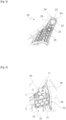
Fig 5 ] représente un agrandissement vu de dessus de la patte d'ancrage avant du boîtier de lafigure 2 ; - [
Fig 6 ] représente un agrandissement vu de face de la patte d'ancrage avant du boîtier de lafigure 2 ; et - [
Fig 7 ] représente un agrandissement en perspective vu de dessous de la patte d'ancrage avant du boîtier de lafigure 2 . - La
figure 1 représente un projecteur 1 d'un véhicule automobile selon l'invention destiné à être monté sur la structure de caisse de ce véhicule en s'intégrant aux contours des pièces de carrosserie adjacentes et à ceux du pare-choc. - Dans la description qui va suivre et par convention, les termes « avant », « arrière », « inférieur », « supérieur », « longitudinal » et « transversal » seront définis par rapport à la position de montage de ce projecteur 1 sur le véhicule.
- Les termes « externe » et « interne » seront quant à eux utilisés pour définir la position relative d'un élément par référence à l'axe longitudinal du véhicule. L'élément le plus proche de cet axe sera ainsi qualifié d'interne par opposition à l'autre élément plus éloigné de ce même axe qui sera quant à lui qualifié d'externe.
- Le projecteur 1 comporte un boîtier 10 comprenant un corps creux principal 11 présentant une ouverture 11A et renfermant un ou plusieurs modules lumineux, tel que notamment un module d'éclairage assurant les fonctions photométriques feu de croisement (couramment désigné sous le terme anglosaxon « low beam ») et feu de route (couramment désigné sous le terme anglosaxon « high beam »), ou encore un module de signalisation du type lanterne et/ou clignotant.
- Ce corps principal creux 11 est refermé par une glace extérieure de couverture transparente 50, venue avantageusement de moulage d'une seule pièce à partir d'un polymère synthétique transparent tel que le polycarbonate (PC) ou le poly-méthacrylate de méthyle (PMMA), et rapportée fixement sur le pourtour périphérique de son ouverture 11A par soudure laser de sorte à assurer une parfaite étanchéité.
- Représenté seul sur la
figure 2 , le boîtier 10 comporte également trois pattes d'ancrage 20, 30, 40 saillant à l'extérieur du corps principal 11 et permettant le montage du projecteur 1 sur la structure de caisse du véhicule. - En l'espèce, ce boîtier 10 comprend :
- une patte d'ancrage arrière 20 saillant selon un plan moyen horizontal à l'arrière dudit corps 11 et suivant une direction sensiblement longitudinale ;
- une patte d'ancrage avant 30 saillant latéralement du côté interne du corps principal 11 ; et
- une patte d'ancrage inférieure 40 saillant en dessous de ce corps principal 11.
- Ces trois pattes d'ancrage 20, 30, 40 sont venues de matière avec le corps 11 du boîtier 10 par moulage à partir d'un polymère thermoplastique approprié tel que l'acrylonitrile butadiène styrène (ABS).
- Représentée de manière agrandie sur la
figure 3 , la patte d'ancrage arrière 20 est pourvue d'un perçage 21 destiné à permettre sa fixation par vissage sur une aile latérale correspondante (non représentée) de la structure du véhicule et par l'intermédiaire d'une vis associée à d'une rondelle d'entretoise comme cela est bien connu de l'art antérieur. - Cette patte d'ancrage arrière 20 présente également des moyens d'indexage anti-translation par emboitement selon un axe vertical, constitués en l'espèce par un pion à section en croix 22 (visible sur la
figure 2 ) s'étendant verticalement depuis sa face inférieure et prévu pour coopérer par emboitement avec un orifice (non représenté) ménagé dans ladite aile latérale. - La patte 20 comporte en outre, au niveau de son extrémité proximale de raccordement avec le corps principal 11 du boîtier 10, une ligne d'affaiblissement frangible (non visible sur les figures) configurée pour rompre lors de la survenance d'un choc avant de sorte à provoquer sa désolidarisation d'avec ce corps principal 11.
- A proximité de son extrémité supérieure, cette patte 20 comprend par ailleurs une zone circulaire d'affaiblissement frangible 23, délimitée par quatre lumières 24 en arc de cercle et configurée pour rompre sous une contrainte verticale d'appui prédéterminée exercée par une butée du capot avant du véhicule en cas de choc entre un piéton et l'avant du véhicule, de sorte à permettre l'enfoncement de ce capot et l'absorption d'une partie de l'énergie de ce choc.
- La face supérieure de la patte 20 est pourvue sur au moins la majeure partie de sa surface d'un réseau de nervures de rigidification en nid d'abeilles 25 destinées à augmenter sa rigidité mécanique.
- Sa face inférieure est également pourvue d'une nervure de soutènement en forme d'équerre 26 s'étendant dans un plan longitudinal vertical et étant adossée à une paroi du corps principal 11 de ce boîtier 10.
- Représentée de manière agrandie sur les
figures 4 à 7 , la patte d'ancrage avant 30, en forme de cornière, comprend une partie proximale 31 s'étendant selon un plan moyen transversal vertical et étant raccordée par l'un de ses bords latéraux au corps principal 11 via une zone de liaison frangible verticale 32 configurée pour rompre sous une contrainte longitudinale de cisaillement prédéterminée. - Tel qu'illustré par la
figure 6 , cette zone de liaison frangible 32 est ici constituée par une pluralité d'appendices de liaison 32A étagés de manière espacée les uns au dessus des autres en étant séparés par des trous d'amorce 32B. - La résistance mécanique au cisaillement longitudinal de cette zone de liaison frangible 32 pourra ainsi être facilement ajustée par retrait ou ajout de matière dans le moule d'injection servant à fabriquer le boîtier 10.
- Selon une variante de réalisation non représentée, la zone de liaison frangible 32 peut être constituée par une ligne de striction présentant une épaisseur réduite.
- Afin d'augmenter sa rigidité mécanique, la face avant de cette partie proximale verticale 31 de la patte 30 est pourvue sur l'ensemble de sa surface d'un réseau de nervures de rigidification en nid d'abeilles 33.
- Toujours dans le but d'améliorer sa rigidité mécanique, la face arrière de cette partie proximale verticale 31 présente également un réseau de nervures de rigidification croisées 34.
- La patte d'ancrage avant 30 comporte également une partie distale 35 s'étendant vers l'arrière et selon un plan moyen horizontal depuis le bord supérieur de la partie proximale 31.
- En référence aux
figures 4 et5 , cette partie distale horizontale 35 présente un perçage 36 destiné à permettre sa fixation par vissage sur l'armature de pare-chocs avant 2 du véhicule et par l'intermédiaire d'une vis associée à une rondelle d'entretoise. - La partie distale horizontale 35 de la patte 30 présente également des moyens de pré-maintien et d'indexage anti-rotation constitués par un trou oblong 37 orienté suivant une direction D radiale à l'axe vertical du pion 22 (voir
figure 5 ) et prévu pour être traversé par un doigt 3 saillant verticalement vers le haut depuis l'armature de pare-chocs 2 et de diamètre correspondant à la largeur dudit trou oblong (voirfigure 4 ). - Afin d'augmenter sa rigidité mécanique, la face supérieure de cette partie distale horizontale 35 est en outre pourvue d'un réseau de nervures de rigidification en nid d'abeilles 38 s'étendant sur l'ensemble de sa surface à l'exception du pourtour périphérique du perçage 36 destiné à recevoir une dite rondelle d'entretoise.
- Tel qu'illustré sur la
figure 7 et de sorte à éviter l'apparition, lors des phases de roulage et du fait du poids relativement important du projecteur 1, de phénomènes vibratoires en flexion au niveau de cette partie distale horizontale 35 de la patte 30, cette dernière comporte deux nervures de soutènement en forme d'équerre 39 s'étendant selon des plans longitudinaux verticaux parallèles entre la face inférieure de cette partie distale horizontale 35 et la face arrière de la partie proximale verticale 31. - Selon des variantes de réalisation non représentées, le nombre de ces nervures de soutènement peut varier en étant compris par exemple entre un et quatre.
- Présentant une forme de L, la patte d'ancrage inférieure 40 s'étend suivant un plan moyen vertical parallèle à la direction D du trou oblong 37 de sorte à éviter les dispersions résiduelles qui seraient nuisibles à la bonne position du projecteur 1.
- Tel qu'illustré sur la
figure 2 , cette patte d'ancrage inférieure 40 comporte une branche proximale 41 raccordée par son bord supérieur au corps principal 11 et orientée verticalement vers le bas, ainsi qu'une branche distale 42 orientée horizontalement et pourvue d'un perçage 43 destiné à permettre sa fixation par vissage sur l'armature de pare-chocs 2 du véhicule et par l'intermédiaire d'une vis associée à une rondelle d'entretoise. - La branche distale 42 de cette patte d'ancrage inférieure 40 est en outre reliée à sa branche proximale 41 par une zone de liaison frangible verticale 44 configurée pour rompre sous une contrainte longitudinale de cisaillement prédéterminée et constituée en l'espèce par une ligne de striction verticale présentant une épaisseur réduite.
- Afin d'augmenter sa rigidité mécanique, la face arrière de la branche proximale 41 est pourvue de trois nervures de soutènement en forme d'équerre 45 s'étendant parallèlement dans des plans longitudinaux verticaux et étant adossées à une paroi du corps principal 11 de ce boîtier 10.
- Selon des variantes de réalisation non représentées, le nombre de ces nervures de soutènement peut varier en étant compris par exemple entre un et quatre.
- Enfin et dans le but d'améliorer sa rigidité, la face avant de cette patte d'ancrage inférieure 40 est pourvue d'un réseau de nervures en nid d'abeilles 46 s'étendant sur l'ensemble de sa surface à l'exception du pourtour périphérique du perçage 43 destiné à recevoir la rondelle d'entretoise.
Claims (9)
- Boîtier (10) de projecteur (1) pour véhicule automobile comportant un corps principal creux (11) apte à recevoir au moins un module lumineux et destiné à être refermé par une glace extérieure de couverture (50), une patte d'ancrage arrière (20) saillant selon un plan moyen horizontal à l'arrière dudit corps (11) et présentant un perçage (21) pour sa fixation par vissage à un premier élément structurel dudit véhicule ainsi que des moyens d'indexage anti-translation par emboitement selon un axe vertical (22), et une patte d'ancrage avant frangible (30) saillant dudit corps (11), du côté dit interne de ce corps en référence à l'axe longitudinal du véhicule, et présentant également un perçage (36) pour sa fixation par vissage à un second élément structurel (2) dudit véhicule ladite patte d'ancrage avant (30), en forme de cornière, comprenant une partie proximale (31) s'étendant selon un plan moyen transversal vertical et étant raccordée par l'un de ses bords latéraux audit corps (11) via une zone de liaison frangible (32) configurée pour rompre sous une contrainte longitudinale de cisaillement prédéterminée, ainsi qu'une partie distale (35) s'étendant vers l'arrière selon un plan moyen horizontal depuis le bord supérieur de ladite partie proximale (31); ce boitier de projecteur comportant de plus une patte d'ancrage inférieure;le boîtier de projecteur étant caractérisé en ce que ladite patte d'ancrage avant frangible (30) présente dans sa partie distale (35) un trou oblong d'indexage anti-rotation (37) s'étendant horizontalement en étant orienté suivant une direction radiale (D) audit axe vertical;en ce que la zone de liaison frangible (32) de la patte d'ancrage avant (30) est une zone de liaison frangible verticale;et en ce que la patte d'ancrage inférieure (40) est en forme de L (40) saillant en dessous dudit corps selon un plan moyen vertical parallèle à ladite direction radiale (D) du trou oblong d'indexage (37), cette patte d'ancrage inférieure (40) comportant une branche proximale (41) d'orientation verticale raccordée par son bord supérieur audit corps (11) ainsi qu'une branche distale (42) orientée horizontalement et pourvue d'un perçage (43) destiné à permettre sa fixation par vissage sur un élément structurel dudit véhicule.
- Boîtier (10) de projecteur (1) selon la revendication 1, caractérisé en ce que ladite zone de liaison frangible verticale (32) est constituée par une pluralité d'appendices de liaison (32A) étagés de manière espacée les uns au dessus des autres en étant séparés par des trous d'amorce (32B).
- Boîtier (10) de projecteur (1) selon l'une des
revendications 1 ou 2, caractérisé en ce que le perçage de fixation (36) de ladite patte d'ancrage avant (30) est ménagé dans sa partie distale horizontale (35). - Boîtier (10) de projecteur (1) selon l'une des
revendications 1 à 3, caractérisé en ce que ladite patte d'ancrage avant (30) comporte au moins une nervure de soutènement en forme d'équerre (39) s'étendant selon un plan longitudinal vertical entre la face inférieure de sa partie distale horizontale (35) et la face arrière de sa partie proximale verticale (31). - Boîtier (10) de projecteur (1) selon l'une des
revendications 1 à 4, caractérisé en ce que ladite patte d'ancrage arrière (20) ainsi que les parties proximale verticale (31) et distale horizontale (35) de ladite patte d'ancrage avant (30) sont pourvues sur au moins l'une de leurs faces d'un réseau de nervures de rigidification (25, 33, 34, 38). - Boîtier (10) de projecteur (1) selon l'une des
revendications 1 à 5, caractérisé en ce que lesdits moyens d'indexage anti-translation comportent un pion (22) s'étendant verticalement depuis la face inférieure de ladite patte d'ancrage arrière (20) et prévu pour coopérer par emboitement avec un orifice ménagé dans un élément structurel dudit véhicule. - Boîtier (10) de projecteur (1) selon l'une des
revendications précédentes, caractérisé en ce que la branche distale (42) de ladite patte d'ancrage inférieure (40) est reliée à la branche proximale (41) de cette patte d'ancrage inférieure (40) par une zone de liaison frangible verticale (44) configurée pour rompre sous une contrainte longitudinale de cisaillement prédéterminée. - Projecteur (1) pour véhicule automobile, comportant un boîtier (10) comprenant un corps principal creux ouvert (11), au moins un module lumineux logé dans ledit corps (11), et une glace extérieure de couverture (50) refermant ledit corps ; caractérisé en ce que ledit boîtier est conforme à l'une des revendications 1 à 7.
- Véhicule automobile caractérisé en ce qu'il comporte au moins un projecteur (1) conforme à la revendication 8.
Applications Claiming Priority (2)
| Application Number | Priority Date | Filing Date | Title |
|---|---|---|---|
| FR2104787A FR3122619A1 (fr) | 2021-05-06 | 2021-05-06 | Projecteur avec patte d’ancrage frangible pourvue d’un trou oblong d’indexage |
| PCT/FR2022/050580 WO2022234198A1 (fr) | 2021-05-06 | 2022-03-29 | Projecteur avec patte d'ancrage frangible pourvue d'un trou oblong d'indexage |
Publications (2)
| Publication Number | Publication Date |
|---|---|
| EP4334173A1 EP4334173A1 (fr) | 2024-03-13 |
| EP4334173B1 true EP4334173B1 (fr) | 2025-05-07 |
Family
ID=76601391
Family Applications (1)
| Application Number | Title | Priority Date | Filing Date |
|---|---|---|---|
| EP22717641.9A Active EP4334173B1 (fr) | 2021-05-06 | 2022-03-29 | Projecteur avec patte d'ancrage frangible pourvue d'un trou oblong d'indexage |
Country Status (4)
| Country | Link |
|---|---|
| EP (1) | EP4334173B1 (fr) |
| CN (1) | CN117279801A (fr) |
| FR (1) | FR3122619A1 (fr) |
| WO (1) | WO2022234198A1 (fr) |
Families Citing this family (1)
| Publication number | Priority date | Publication date | Assignee | Title |
|---|---|---|---|---|
| FR3148948B1 (fr) | 2023-05-26 | 2025-12-19 | Psa Automobiles Sa | Véhicule automobile à projecteurs encastrés dans le bouclier de pare-chocs avant |
Family Cites Families (7)
| Publication number | Priority date | Publication date | Assignee | Title |
|---|---|---|---|---|
| US3656069A (en) | 1970-07-15 | 1972-04-11 | Bell Telephone Labor Inc | Multiphase digital modulator |
| CN103802721B (zh) * | 2012-11-06 | 2017-11-21 | 标致雪铁龙(中国)汽车贸易有限公司 | 一种用于车辆大灯组件的安装装置及其安装方法 |
| JP5997381B2 (ja) * | 2013-07-02 | 2016-09-28 | 本田技研工業株式会社 | ヘッドライト固定構造 |
| FR3067306B1 (fr) * | 2017-06-08 | 2020-08-28 | Peugeot Citroen Automobiles Sa | Bloc optique pour vehicule automobile |
| DE102017216064B3 (de) * | 2017-09-12 | 2018-11-15 | Ford Global Technologies, Llc | Bauteilgruppe für eine Fahrzeugkarosserie |
| FR3076504A1 (fr) * | 2018-01-05 | 2019-07-12 | Psa Automobiles Sa | Boitier de bloc optique et patte de fixation de substitution pour la reparation d’un tel bloc optique de vehicule |
| FR3086227B1 (fr) * | 2018-09-24 | 2020-10-02 | Renault Sas | Support de projecteur de vehicule automobile. |
-
2021
- 2021-05-06 FR FR2104787A patent/FR3122619A1/fr active Pending
-
2022
- 2022-03-29 WO PCT/FR2022/050580 patent/WO2022234198A1/fr not_active Ceased
- 2022-03-29 EP EP22717641.9A patent/EP4334173B1/fr active Active
- 2022-03-29 CN CN202280033225.XA patent/CN117279801A/zh active Pending
Also Published As
| Publication number | Publication date |
|---|---|
| WO2022234198A1 (fr) | 2022-11-10 |
| EP4334173A1 (fr) | 2024-03-13 |
| CN117279801A (zh) | 2023-12-22 |
| FR3122619A1 (fr) | 2022-11-11 |
Similar Documents
| Publication | Publication Date | Title |
|---|---|---|
| EP0720935B1 (fr) | Dispositif pour le positionnement précis d'un pare-chocs sur une aile d'un véhicule | |
| EP1232932A1 (fr) | Ensemble de bloc avant de véhicule automobile comportant un dispositif amélioré de fixation des composants, et véhicule équipé d'un tel ensemble | |
| FR2703961A1 (fr) | Projecteur pour véhicule automobile, à moyens de montage perfectionnés. | |
| EP2766220A1 (fr) | Support de projecteur pour vehicule automobile et projecteur correspondant | |
| FR2825128A1 (fr) | Support antivibratoire et procede de fabrication d'un tel support | |
| EP1397284B1 (fr) | Face avant de vehicule automobile avec equipements integres | |
| EP4334173B1 (fr) | Projecteur avec patte d'ancrage frangible pourvue d'un trou oblong d'indexage | |
| EP1048521B1 (fr) | Dispositif de montage d'un bloc optique sur des éléments de carrosserie d'un véhicule automobile | |
| EP1616753B1 (fr) | Dispositif d'éclairage pour véhicule automobile à sécurité renforcée en cas de choc | |
| FR2867734A1 (fr) | Dispositif de fixation d'un bloc optique sur la structure d'un vehicule automobile, integrant des moyens d'amortissement d'un choc pieton | |
| FR3099907A1 (fr) | Déflecteur aérodynamique arrière pour véhicule automobile | |
| EP3983279B1 (fr) | Moyens de renfort pour une structure avant de véhicule automobile | |
| FR2978412A1 (fr) | Module de face avant de vehicule automobile. | |
| FR3100597A1 (fr) | Projecteur avant de vehicule a fixation fusible et vehicule comportant un tel projecteur | |
| FR3148948A1 (fr) | Véhicule automobile à projecteurs encastrés dans le bouclier de pare-chocs avant | |
| FR3086227A1 (fr) | Support de projecteur de vehicule automobile. | |
| WO2008017774A1 (fr) | Ouvrant de vehicule automobile comprenant un raidisseur et vehicule muni un tel ouvrant | |
| EP2039569B1 (fr) | Support de pare-choc coopérant avec des supports de feu de véhicule automobile | |
| WO2023135372A1 (fr) | Boîtier de projecteur pour véhicule automobile pourvu d'une rampe de guidage | |
| FR3140331A1 (fr) | Obturateur pour garniture intérieure de véhicule automobile et véhicule automobile équipé d’un tel obturateur | |
| WO2024146991A1 (fr) | Bloc optique de véhicule automobile doté de moyens de maintien de la peau de pare-chocs | |
| EP4347321A1 (fr) | Support de fixation de deux equipements de vehicule | |
| WO2024175840A1 (fr) | Bloc optique de signalisation destiné à être intégré dans un projecteur de véhicule automobile | |
| WO2024110714A1 (fr) | Interface de fixation fusible pour solidariser un élément de pare-chocs et un boîtier de projecteur | |
| WO2024062171A1 (fr) | Système d'assemblage d'un masque de projecteur pour véhicule automobile sur un réflecteur en matériau thermodurcissable |
Legal Events
| Date | Code | Title | Description |
|---|---|---|---|
| STAA | Information on the status of an ep patent application or granted ep patent |
Free format text: STATUS: UNKNOWN |
|
| STAA | Information on the status of an ep patent application or granted ep patent |
Free format text: STATUS: THE INTERNATIONAL PUBLICATION HAS BEEN MADE |
|
| PUAI | Public reference made under article 153(3) epc to a published international application that has entered the european phase |
Free format text: ORIGINAL CODE: 0009012 |
|
| STAA | Information on the status of an ep patent application or granted ep patent |
Free format text: STATUS: REQUEST FOR EXAMINATION WAS MADE |
|
| 17P | Request for examination filed |
Effective date: 20231020 |
|
| AK | Designated contracting states |
Kind code of ref document: A1 Designated state(s): AL AT BE BG CH CY CZ DE DK EE ES FI FR GB GR HR HU IE IS IT LI LT LU LV MC MK MT NL NO PL PT RO RS SE SI SK SM TR |
|
| DAV | Request for validation of the european patent (deleted) | ||
| DAX | Request for extension of the european patent (deleted) | ||
| GRAP | Despatch of communication of intention to grant a patent |
Free format text: ORIGINAL CODE: EPIDOSNIGR1 |
|
| STAA | Information on the status of an ep patent application or granted ep patent |
Free format text: STATUS: GRANT OF PATENT IS INTENDED |
|
| INTG | Intention to grant announced |
Effective date: 20250116 |
|
| GRAS | Grant fee paid |
Free format text: ORIGINAL CODE: EPIDOSNIGR3 |
|
| GRAA | (expected) grant |
Free format text: ORIGINAL CODE: 0009210 |
|
| STAA | Information on the status of an ep patent application or granted ep patent |
Free format text: STATUS: THE PATENT HAS BEEN GRANTED |
|
| AK | Designated contracting states |
Kind code of ref document: B1 Designated state(s): AL AT BE BG CH CY CZ DE DK EE ES FI FR GB GR HR HU IE IS IT LI LT LU LV MC MK MT NL NO PL PT RO RS SE SI SK SM TR |
|
| REG | Reference to a national code |
Ref country code: GB Ref legal event code: FG4D Free format text: NOT ENGLISH |
|
| REG | Reference to a national code |
Ref country code: CH Ref legal event code: EP |
|
| REG | Reference to a national code |
Ref country code: DE Ref legal event code: R096 Ref document number: 602022014317 Country of ref document: DE |
|
| REG | Reference to a national code |
Ref country code: IE Ref legal event code: FG4D Free format text: LANGUAGE OF EP DOCUMENT: FRENCH |
|
| REG | Reference to a national code |
Ref country code: DE Ref legal event code: R084 Ref document number: 602022014317 Country of ref document: DE |
|
| REG | Reference to a national code |
Ref country code: NL Ref legal event code: MP Effective date: 20250507 |
|
| PG25 | Lapsed in a contracting state [announced via postgrant information from national office to epo] |
Ref country code: FI Free format text: LAPSE BECAUSE OF FAILURE TO SUBMIT A TRANSLATION OF THE DESCRIPTION OR TO PAY THE FEE WITHIN THE PRESCRIBED TIME-LIMIT Effective date: 20250507 Ref country code: PT Free format text: LAPSE BECAUSE OF FAILURE TO SUBMIT A TRANSLATION OF THE DESCRIPTION OR TO PAY THE FEE WITHIN THE PRESCRIBED TIME-LIMIT Effective date: 20250908 Ref country code: ES Free format text: LAPSE BECAUSE OF FAILURE TO SUBMIT A TRANSLATION OF THE DESCRIPTION OR TO PAY THE FEE WITHIN THE PRESCRIBED TIME-LIMIT Effective date: 20250507 |
|
| REG | Reference to a national code |
Ref country code: LT Ref legal event code: MG9D |
|
| PG25 | Lapsed in a contracting state [announced via postgrant information from national office to epo] |
Ref country code: NO Free format text: LAPSE BECAUSE OF FAILURE TO SUBMIT A TRANSLATION OF THE DESCRIPTION OR TO PAY THE FEE WITHIN THE PRESCRIBED TIME-LIMIT Effective date: 20250807 Ref country code: GR Free format text: LAPSE BECAUSE OF FAILURE TO SUBMIT A TRANSLATION OF THE DESCRIPTION OR TO PAY THE FEE WITHIN THE PRESCRIBED TIME-LIMIT Effective date: 20250808 |
|
| PG25 | Lapsed in a contracting state [announced via postgrant information from national office to epo] |
Ref country code: NL Free format text: LAPSE BECAUSE OF FAILURE TO SUBMIT A TRANSLATION OF THE DESCRIPTION OR TO PAY THE FEE WITHIN THE PRESCRIBED TIME-LIMIT Effective date: 20250507 Ref country code: PL Free format text: LAPSE BECAUSE OF FAILURE TO SUBMIT A TRANSLATION OF THE DESCRIPTION OR TO PAY THE FEE WITHIN THE PRESCRIBED TIME-LIMIT Effective date: 20250507 |
|
| REG | Reference to a national code |
Ref country code: AT Ref legal event code: MK05 Ref document number: 1792134 Country of ref document: AT Kind code of ref document: T Effective date: 20250507 |
|
| PG25 | Lapsed in a contracting state [announced via postgrant information from national office to epo] |
Ref country code: BG Free format text: LAPSE BECAUSE OF FAILURE TO SUBMIT A TRANSLATION OF THE DESCRIPTION OR TO PAY THE FEE WITHIN THE PRESCRIBED TIME-LIMIT Effective date: 20250507 |
|
| PG25 | Lapsed in a contracting state [announced via postgrant information from national office to epo] |
Ref country code: HR Free format text: LAPSE BECAUSE OF FAILURE TO SUBMIT A TRANSLATION OF THE DESCRIPTION OR TO PAY THE FEE WITHIN THE PRESCRIBED TIME-LIMIT Effective date: 20250507 |
|
| PG25 | Lapsed in a contracting state [announced via postgrant information from national office to epo] |
Ref country code: AT Free format text: LAPSE BECAUSE OF FAILURE TO SUBMIT A TRANSLATION OF THE DESCRIPTION OR TO PAY THE FEE WITHIN THE PRESCRIBED TIME-LIMIT Effective date: 20250507 |
|
| PG25 | Lapsed in a contracting state [announced via postgrant information from national office to epo] |
Ref country code: RS Free format text: LAPSE BECAUSE OF FAILURE TO SUBMIT A TRANSLATION OF THE DESCRIPTION OR TO PAY THE FEE WITHIN THE PRESCRIBED TIME-LIMIT Effective date: 20250807 |
|
| PG25 | Lapsed in a contracting state [announced via postgrant information from national office to epo] |
Ref country code: IS Free format text: LAPSE BECAUSE OF FAILURE TO SUBMIT A TRANSLATION OF THE DESCRIPTION OR TO PAY THE FEE WITHIN THE PRESCRIBED TIME-LIMIT Effective date: 20250907 |
|
| PG25 | Lapsed in a contracting state [announced via postgrant information from national office to epo] |
Ref country code: LV Free format text: LAPSE BECAUSE OF FAILURE TO SUBMIT A TRANSLATION OF THE DESCRIPTION OR TO PAY THE FEE WITHIN THE PRESCRIBED TIME-LIMIT Effective date: 20250507 |
|
| PG25 | Lapsed in a contracting state [announced via postgrant information from national office to epo] |
Ref country code: DK Free format text: LAPSE BECAUSE OF FAILURE TO SUBMIT A TRANSLATION OF THE DESCRIPTION OR TO PAY THE FEE WITHIN THE PRESCRIBED TIME-LIMIT Effective date: 20250507 Ref country code: SM Free format text: LAPSE BECAUSE OF FAILURE TO SUBMIT A TRANSLATION OF THE DESCRIPTION OR TO PAY THE FEE WITHIN THE PRESCRIBED TIME-LIMIT Effective date: 20250507 |
|
| PG25 | Lapsed in a contracting state [announced via postgrant information from national office to epo] |
Ref country code: CZ Free format text: LAPSE BECAUSE OF FAILURE TO SUBMIT A TRANSLATION OF THE DESCRIPTION OR TO PAY THE FEE WITHIN THE PRESCRIBED TIME-LIMIT Effective date: 20250507 |
|
| PG25 | Lapsed in a contracting state [announced via postgrant information from national office to epo] |
Ref country code: EE Free format text: LAPSE BECAUSE OF FAILURE TO SUBMIT A TRANSLATION OF THE DESCRIPTION OR TO PAY THE FEE WITHIN THE PRESCRIBED TIME-LIMIT Effective date: 20250507 |
|
| PG25 | Lapsed in a contracting state [announced via postgrant information from national office to epo] |
Ref country code: SK Free format text: LAPSE BECAUSE OF FAILURE TO SUBMIT A TRANSLATION OF THE DESCRIPTION OR TO PAY THE FEE WITHIN THE PRESCRIBED TIME-LIMIT Effective date: 20250507 |
|
| PG25 | Lapsed in a contracting state [announced via postgrant information from national office to epo] |
Ref country code: IT Free format text: LAPSE BECAUSE OF FAILURE TO SUBMIT A TRANSLATION OF THE DESCRIPTION OR TO PAY THE FEE WITHIN THE PRESCRIBED TIME-LIMIT Effective date: 20250507 |
|
| REG | Reference to a national code |
Ref country code: DE Ref legal event code: R097 Ref document number: 602022014317 Country of ref document: DE |
|
| PLBE | No opposition filed within time limit |
Free format text: ORIGINAL CODE: 0009261 |
|
| STAA | Information on the status of an ep patent application or granted ep patent |
Free format text: STATUS: NO OPPOSITION FILED WITHIN TIME LIMIT |
|
| REG | Reference to a national code |
Ref country code: CH Ref legal event code: L10 Free format text: ST27 STATUS EVENT CODE: U-0-0-L10-L00 (AS PROVIDED BY THE NATIONAL OFFICE) Effective date: 20260318 |
|
| PGFP | Annual fee paid to national office [announced via postgrant information from national office to epo] |
Ref country code: DE Payment date: 20260219 Year of fee payment: 5 |
|
| 26N | No opposition filed |
Effective date: 20260210 |
|
| PGFP | Annual fee paid to national office [announced via postgrant information from national office to epo] |
Ref country code: FR Payment date: 20260219 Year of fee payment: 5 |