EP4333463A1 - Method for monitoring an in-ear placement of a hearing device - Google Patents
Method for monitoring an in-ear placement of a hearing device Download PDFInfo
- Publication number
- EP4333463A1 EP4333463A1 EP22193220.5A EP22193220A EP4333463A1 EP 4333463 A1 EP4333463 A1 EP 4333463A1 EP 22193220 A EP22193220 A EP 22193220A EP 4333463 A1 EP4333463 A1 EP 4333463A1
- Authority
- EP
- European Patent Office
- Prior art keywords
- feedback path
- hearing device
- feedback
- gain
- signal
- Prior art date
- Legal status (The legal status is an assumption and is not a legal conclusion. Google has not performed a legal analysis and makes no representation as to the accuracy of the status listed.)
- Pending
Links
- 238000000034 method Methods 0.000 title claims abstract description 52
- 238000012544 monitoring process Methods 0.000 title claims abstract description 11
- 238000012545 processing Methods 0.000 claims abstract description 51
- 230000005236 sound signal Effects 0.000 claims abstract description 21
- 210000000613 ear canal Anatomy 0.000 claims abstract description 13
- 230000008569 process Effects 0.000 claims abstract description 6
- 230000004044 response Effects 0.000 claims description 8
- 239000013598 vector Substances 0.000 claims description 6
- 230000000007 visual effect Effects 0.000 claims description 5
- 230000003213 activating effect Effects 0.000 claims description 3
- 230000006870 function Effects 0.000 description 17
- 238000012546 transfer Methods 0.000 description 13
- 101100460844 Mus musculus Nr2f6 gene Proteins 0.000 description 8
- 238000013459 approach Methods 0.000 description 6
- 238000010586 diagram Methods 0.000 description 5
- 238000013016 damping Methods 0.000 description 4
- 230000010370 hearing loss Effects 0.000 description 4
- 231100000888 hearing loss Toxicity 0.000 description 4
- 208000016354 hearing loss disease Diseases 0.000 description 4
- 230000007246 mechanism Effects 0.000 description 4
- 206010011878 Deafness Diseases 0.000 description 3
- 230000006978 adaptation Effects 0.000 description 3
- 230000000694 effects Effects 0.000 description 3
- 239000000243 solution Substances 0.000 description 3
- 230000003595 spectral effect Effects 0.000 description 3
- 230000008878 coupling Effects 0.000 description 2
- 238000010168 coupling process Methods 0.000 description 2
- 238000005859 coupling reaction Methods 0.000 description 2
- 230000007423 decrease Effects 0.000 description 2
- 238000001514 detection method Methods 0.000 description 2
- 238000005562 fading Methods 0.000 description 2
- 238000005259 measurement Methods 0.000 description 2
- 238000007789 sealing Methods 0.000 description 2
- 238000001228 spectrum Methods 0.000 description 2
- 230000003044 adaptive effect Effects 0.000 description 1
- 230000033228 biological regulation Effects 0.000 description 1
- 230000006835 compression Effects 0.000 description 1
- 238000007906 compression Methods 0.000 description 1
- 230000009849 deactivation Effects 0.000 description 1
- 238000000354 decomposition reaction Methods 0.000 description 1
- 230000001419 dependent effect Effects 0.000 description 1
- 238000013461 design Methods 0.000 description 1
- 238000011161 development Methods 0.000 description 1
- 230000005284 excitation Effects 0.000 description 1
- 238000001914 filtration Methods 0.000 description 1
- 238000011065 in-situ storage Methods 0.000 description 1
- 238000002347 injection Methods 0.000 description 1
- 239000007924 injection Substances 0.000 description 1
- 238000012986 modification Methods 0.000 description 1
- 230000004048 modification Effects 0.000 description 1
- 230000009467 reduction Effects 0.000 description 1
- 238000009738 saturating Methods 0.000 description 1
- 230000003068 static effect Effects 0.000 description 1
- 238000012360 testing method Methods 0.000 description 1
- 238000012549 training Methods 0.000 description 1
- 210000003454 tympanic membrane Anatomy 0.000 description 1
Images


Classifications
-
- H—ELECTRICITY
- H04—ELECTRIC COMMUNICATION TECHNIQUE
- H04R—LOUDSPEAKERS, MICROPHONES, GRAMOPHONE PICK-UPS OR LIKE ACOUSTIC ELECTROMECHANICAL TRANSDUCERS; DEAF-AID SETS; PUBLIC ADDRESS SYSTEMS
- H04R25/00—Deaf-aid sets, i.e. electro-acoustic or electro-mechanical hearing aids; Electric tinnitus maskers providing an auditory perception
- H04R25/45—Prevention of acoustic reaction, i.e. acoustic oscillatory feedback
- H04R25/453—Prevention of acoustic reaction, i.e. acoustic oscillatory feedback electronically
-
- H—ELECTRICITY
- H04—ELECTRIC COMMUNICATION TECHNIQUE
- H04R—LOUDSPEAKERS, MICROPHONES, GRAMOPHONE PICK-UPS OR LIKE ACOUSTIC ELECTROMECHANICAL TRANSDUCERS; DEAF-AID SETS; PUBLIC ADDRESS SYSTEMS
- H04R25/00—Deaf-aid sets, i.e. electro-acoustic or electro-mechanical hearing aids; Electric tinnitus maskers providing an auditory perception
- H04R25/30—Monitoring or testing of hearing aids, e.g. functioning, settings, battery power
- H04R25/305—Self-monitoring or self-testing
-
- H—ELECTRICITY
- H04—ELECTRIC COMMUNICATION TECHNIQUE
- H04R—LOUDSPEAKERS, MICROPHONES, GRAMOPHONE PICK-UPS OR LIKE ACOUSTIC ELECTROMECHANICAL TRANSDUCERS; DEAF-AID SETS; PUBLIC ADDRESS SYSTEMS
- H04R2460/00—Details of hearing devices, i.e. of ear- or headphones covered by H04R1/10 or H04R5/033 but not provided for in any of their subgroups, or of hearing aids covered by H04R25/00 but not provided for in any of its subgroups
- H04R2460/15—Determination of the acoustic seal of ear moulds or ear tips of hearing devices
Definitions
- the invention relates to a method for monitoring an in-ear placement of a hearing device.
- an earpiece of the hearing device When a hearing device is fitted to a user by an audiologist, an earpiece of the hearing device is placed in a desired (target) position in an ear canal of the user. Once the earpiece is in the desired position, processing parameters of the hearing device are set according to a prescribed gain model in order to compensate the hearing loss of the user. The gain is thereby adjusted to avoid squealing of the hearing device due to acoustic feedback. Feedback may occur when sound emitted by a receiver of the hearing device travels back to a microphone of the hearing device thus creating a feedback loop. This is particularly critical in cases where a high gain model is applied during audio processing in the hearing device.
- the proneness for a feedback loop to develop is significantly increased if the in-ear placement of the earpiece of the hearing device is not as desired, i.e. the earpiece is not in the desired target position, as an insufficient seal between the earpiece and the ear canal leads to acoustic leakage between the microphone and the receiver.
- a feedback results in an unwanted and in particular uncomfortable squealing sound of the hearing device
- development of a feedback loop needs to be avoided during normal operation of the hearing device.
- One method for avoiding such a squealing sound includes applying a feedback cancelling algorithm during audio processing in the hearing device.
- the feedback cancelling algorithm may be based on adaptive filtering of the input signal provided by the microphone, wherein the occurrence of feedback is continuously suppressed.
- Such a feedback cancelling algorithm may at the same time reduce the gain of the hearing device or may lead to unpleasant artefacts in the sound of the hearing device which is output to the user.
- applying a feedback cancelling algorithm generally provides for an optimal compromise.
- the position of the earpiece is typically not detected or monitored, resulting in discrepancies between an actual gain provided by the hearing device and a prescribed gain. This is a problem in particular, when the hearing device is used by an unexperienced user, who may have difficulties to correctly place the earpiece of the hearing device in a target position in his ear canal.
- the start of the processing may be postponed after starting the hearing device; however this results in a delay before starting the hearing device and may thus be unsatisfying.
- the object is achieved by a method for monitoring an in-ear placement of a hearing device according to claim 1.
- the term feedback path in the context of the present invention may include a feedback gain and a feedback phase.
- An audio signal in the present context may be any electrical signal which carries acoustic information.
- an audio signal may comprise unprocessed or raw audio data, for example raw audio wave forms, and/or processed audio data, for example extracted audio features, compressed audio data, a spectrum, in particular a frequency spectrum, a cepstrum and/or cepstral coefficients and/or otherwise modified audio data.
- the present invention proposes a method for monitoring an in-ear placement of a hearing device which is configured to be worn at least partially in an ear canal, the hearing device comprising
- the squealing sound may stop by itself when the actual feedback path is close to the reference feedback path and the hearing device may start normal operation.
- a feedback canceller may suppress squealing.
- Normal operation of a hearing device in the context of the present invention may denote an operational mode in which a maximum possible gain setting for the hearing device is determined and applied, e.g. by determining a feedback threshold, i.e. a maximum gain setting for a hearing device, for which maximum gain setting there occurs only just no signal feedback, in particular as described in EP 1 624 719 A2 .
- the processing unit is configured to operate as a feedback canceller to suppress acoustic feedback from the receiver to the microphone.
- the feedback canceller is used as a compensation unit.
- the target location for which a reference in-ear placement is defined is one of an ear canal of a user and a charger for the hearing device.
- the coefficients of the filter are impulse response coefficients or frequency response coefficients.
- an output is generated encouraging a user to stop touching the hearing device when having corrected the position thereof.
- an input of a gain model block is provided with a compensated signal obtained by subtracting an output signal of a filter block representing the reference feedback path from an input signal.
- a Euclidian distance between complex vectors constituted by the filter coefficients of the actual feedback path and the reference feedback path is calculated to assess whether the actual feedback path equals the reference feedback path within the predetermined margin.
- a distance between a modulus of complex vectors constituted by the filter coefficients of the actual feedback path and the reference feedback path is calculated to assess whether the actual feedback path equals the reference feedback path within the predetermined margin.
- a maximum gain is set in the feedback threshold gain model before activating the processing unit.
- a visual signal is output once the actual feedback path equals the reference feedback path within the predetermined margin.
- the visual signal is output on a mobile device wirelessly connected to the hearing device.
- setting the gain model to generate feedback includes:
- these steps are performed separately for each one of a plurality of frequency bands.
- the coefficients of the feedback canceller may be adapted to accommodate for discrepancies due to the presence of the hand of the user. This may be a slow, full adaptation or only a partial adaptation of only the phase component.
- a hearing device is proposed, wherein the hearing device is configured to perform the above described method.
- the hearing device may start to whistle before it is introduced and inserted properly in the ear canal.
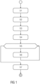
- Figure 1 is a schematic flowchart of an exemplary embodiment of a method for monitoring an in-ear placement of a hearing device 1, e.g. in a user's ear 2 or in a charger.
- Figure 2 is a schematic view of the method using pictograms.
- the hearing device 1 comprises a receiver configured for playing back sound in an ear canal of the user, at least one microphone configured for obtaining an audio signal from received ambient sound, and a processing unit 100 configured to process the audio signal, wherein the receiver is configured for outputting sound to the ear canal based on the processed audio signal, the processing unit configured to filter signals played back on the receiver or picked up from the sound played back by the receiver with a filter representing a feedback path having a feedback gain and a feedback phase and to subtract the filtered signals from the sound signal picked up by the microphone.
- a step S1 the hearing device 1 is started.
- reference values Ho of a filter representing a physical reference feedback path of the hearing device 1 are loaded and applied to the filter of the processing unit.
- the reference values Ho may apply to a situation such as that the hearing device 1 or an earpiece 3 thereof is correctly placed in a user's ear 2 or in a charger.
- the reference values may be determined by a measurement in situ, i.e. in the ear 2 or in the charger. This measurement may be performed by the user or by a hearing care professional.
- the reference values Ho may be the impulse response, the transfer function or the frequency response of the filter. More specifically, the reference values Ho may be implemented by filter coefficients, e.g. impulse response coefficients in the time domain or frequency response coefficients in the frequency domain.
- the hearing device 1 outputs sound by the receiver.
- a step S4 the hearing device 1 or an earpiece 3 thereof is being placed into or toward a target location such as the user's ear 2 while the sound is still being output.
- the actual feedback path converges toward the reference feedback path as the hearing device 1 approaches the target location due to the user adjusting it in a step S5 so the volume of the sound output gradually reduces or is gradually reduced in a step S6.
- the processing unit may be configured as a feedback canceller configured to suppress acoustic feedback from the receiver to the microphone.
- the active mechanism may be configured to use the feedback canceler to estimate the actual feedback path, which can then be compared to the reference feedback path.
- the sealing i.e. the correct in-ear placement of the hearing device 1, is therefore actively monitored, and can be used to control an audio output signal level, which provides a feedback to the user about how well the sealing currently is.
- Figure 3 is a schematic flowchart of the active variant of the method.
- the hearing device 1 is started.
- the feedback canceller is activated on the whole frequency range.
- the feedback canceller may be configured to work on a reduced frequency range, for instance from frequency 1700Hz to 8500Hz). It is only active at frequencies where there is a risk of feedback.
- the compensation is applied as broadly as possible hence the feedback canceller is set to operate on the whole frequency range.
- this frequency range may be configurable in order to discard certain frequencies, for instance very low frequencies and/or very high frequencies.
- the hearing device 1 outputs sound by the receiver, e.g. it plays back sine waves while the ambient audio, i.e. sound picked up by the microphone, is bypassed.
- a step S4 the hearing device 1 or an earpiece 3 thereof is placed into a target location such as the user's ear 2 while the sound is still being output.
- the actual feedback path converges toward the reference feedback path as the hearing device 1 approaches the target location due to the user adjusting it in a step S5 so the feedback coefficients are updated in a step S6.1 and the volume of the sound output gradually reduces or is gradually reduced in a step S6.2.
- the hearing device 1 stops outputting the sound and starts normal operation in a step S7.
- the output sound level is explicitly or actively reduced. This creates a sound that is gradually fading away.
- the method is performed independently in each of a number of several frequency bands.
- the sound generation in a previously stopped band may be reactivated upon the detection that the hearing device 1 was moved away from the target location, i.e. the actual feedback path diverges from the reference feedback path.
- Figure 4 is a schematic flowchart of the passive variant of the method.
- step S1 the hearing device 1 is started.
- step S2 the feedback canceller is activated on the whole frequency range.
- reference values Ho i.e. filter coefficients, of a filter representing a physical reference feedback path of the hearing device 1 are loaded and applied to the filter of the processing unit.
- a gain model designed to determine a feedback threshold (also referred to as a feedback threshold gain model), e.g. as described in EP 1 624 719 A2 , is started, consequently the hearing device 1 outputs sound by the receiver at a sound level enforced by the gain model, e.g. a squealing sound due to the actual feedback path outside the target location, i.e. the user's ear 2 or the charger, differing from the reference feedback path.
- the gain is set such that it generates a feedback condition.
- the gain model is embodied in a processing unit which uses a sound level of a hearing device input signal, e.g. a microphone signal, as an input and computes a gain to be applied to the input signal to generate an output signal.
- a step S4 the hearing device 1 or an earpiece 3 thereof is placed into a target location such as the user's ear 2 while the sound is still being output.
- the actual feedback path converges toward the reference feedback path as the hearing device 1 approaches the target location due to the user adjusting it in a step S5 so the gain model computes the gain in a step S6.1, i.e. at each processing frame (or interval), the processing unit running the gain model will compute the sound level of the input signal, then compute the corresponding gain, e.g. according to the feedback threshold gain model, and multiply the input signal with this computed gain to generate the output signal.
- the feedback canceller coefficients are updated in a step S6.2, e.g. with regard to its phases, not its magnitudes. In other embodiments, the whole complex feedback canceller coefficients could be updated very slowly, or could not be updated at all.
- the volume of the sound output gradually reduces in a step S6.3.
- the output level is not directly controlled. Instead, a parameter of the gain model that relates to the output level, e.g. a target output, is modified.
- a parameter of the gain model that relates to the output level, e.g. a target output, is modified.
- the parameter b is an offset related to the target output. Lowering the offset b over time then allows to indirectly reduce the output level.
- the phase of the feedback canceller coefficients may be adapted using a least mean squares algorithm, in particular a normalized least mean squares algorithm, while the magnitudes are kept.
- the hearing device 1 stops outputting the sound and starts normal operation in a step S7.
- the passive version uses a similar principle to the feedback threshold gain model as described in EP 1 624 719 A2 : the hearing device 1 will whistle as long as the feedback path is not close enough to the reference feedback path defined by the reference values Ho, thanks to the special gain model. Indeed, with this gain computation, the output of the hearing device 1 is controlled to reach a desired level. This gain may depend on the (noise) input level, feedback path and desired output level. This gain model saturates when it reaches the maximum allowable gain of the hearing device 1. If we activate the feedback canceller, in static mode and initialized with a reference path defined by the reference values Ho, the feedback path, from the device point of view, will then be equal to the difference between the physical and the electric paths: H-Ho.
- the gain in this gain model, tends to be inverse proportional to the feedback gain
- the coefficients of the feedback canceller may optionally be updated as well, but only the phase terms of the complex coefficients, thus preserving the global spectral shape of the reference feedback path.
- the gain model causes the volume of the sound output to be high only when the difference of the actual feedback path from the reference feedback path is rather high. As the actual feedback path converges toward the reference feedback path, the gain of the gain model is maximized and the hearing device 1 stops squealing and starts normal operation. In normal operation, the feedback canceller may suppress squealing. In an exemplary embodiment, normal operation is started and the squealing stops.
- a melody or a tone sequence may be output which may be more comfortable to listen to. If a remote device is available, the melody may be streamed from or via the remote device.
- the passive solution does not need to actively generate sound and adapt it to the acoustic situation. Instead, the sound is automatically generated and thus automatically fades away as the acoustic coupling gets close to the reference.
- the algorithm shown in Figure 4 may be performed independently in each one of a plurality of frequency bands. This can be done simultaneously in all bands, or as a sequence, one band after the other. In this scenario, there may be a loop over the frequency bands, encapsulating the loop that includes steps S6.1, S6.2, S6.3 in figure 4 . In this case, in step S6.1 the gain is set to 0 in all bands, except for the active band, i.e. the currently considered band, where the gain model is set to determine the feedback threshold in that band.
- the condition in step S5 to skip to step S7 also includes the fact that the gain has to be high enough in all the tested bands.
- the order in which the frequency bands are cycled through is not important for the performance. Hence, an arbitrary order can be chosen such that the resulting audio output is the most comfortable one to the end-user. For instance, a seemingly random sequence may make the audio output more enjoyable and less monotonic.
- Both, the active and the passive variant may be configurable and have a timeout parameter. Otherwise, the active variant stops after the threshold on the estimated feedback path is reached. The passive variant stops when the maximum gain is hit.
- different tones may be used to help the user differentiate the left and the right hearing device 1, before placing the earpieces 3 in the ear 2, in case notably when the hearing devices 1 are not very different otherwise.
- in-ear placement may be used in addition, e.g. an in-ear-canal microphone, or a skin contact captor.
- a visual cue displayed on a screen of a mobile device could further help the user recognize correct placement, or even replace the audio cue, thus making the process silent and possibly more pleasant.
- a hard switch between the startup and normal operation may not be necessary.
- the above mechanisms could probably also operate in a continuous manner, for instance by acting on gain fading mechanisms, reducing the gain while the position of the hearing device 1 is unsatisfying, and raising the gain to normal operation when the position is deemed correct.
- the final audible sound design may be configurable.
- the generated signal may be configured almost arbitrarily, while with the passive method, this may be more limited.
- the hearing device 1 may be configurable by the user to allow for de-activating the described method, e.g. if they decide that they are able to place the hearing device 1 or the earpiece 3 thereof well enough without assistance.
- the hand of the user may have a contribution to the feedback path.
- the user may thus be encouraged to remove their hand after correcting the placement, e.g. by an audio message or by a hint in a user's manual.
- the spectral shape of the sound output may be modified in accordance to the detected feedback path, modifying the energy output in a given frequency channel with respect to the in-ear placement in that channel.
- the generated sound helps guiding the user such that they know whether they are far from the optimal position (loud excitation) or close to it (very soft / inaudible signal). For mild and higher hearing losses, this could however mean that the generated sound should be as loud as needed, such that the user can actually hear it.
- a user may be able to associate spectral characteristics to the actual acoustic coupling.
- the presently proposed method does not necessarily require a tool for placing the earpiece 3, although this could be helpful, notably in order to avoid to have a discrepancy between the reference feedback path and the measured one, which is then "polluted" by the presence of the user's fingers and hand.
- the processing unit is indeed not designed to generate a sound, but rather to modify the input, i.e. the ambient sound, by enforcing the output to reach a desired level.
- This processing automatically results in gains equal to the inverse of the feedback path, provided that sufficiently high gain is available.
- the passive approach does not modify the gain model depending on the proximity to the reference, but proposes to modify the input signal of the gain model such that the input signal of the gain model is the signal from which the reference feedback signal has been removed, optionally adapted to accommodate for discrepancies due to the presence of the hand of the user. This means that such a system would not need to explicitly steer the output power, but rather automatically and implicitly stops creating feedback as the acoustic situation comes close to the reference situation.
- the passive approach may perform the following steps:
- Step 1 is based on the following considerations: a hearing aid is characterized by a processing block referred to as the gain model or embodying such a gain model, in order to compensate a hearing loss.
- the present invention proposes to reuse the same gain model processing block, as in EP 1 624 719 A2 to determine a "feedback threshold" - leading to the "feedback test” procedure.
- the gain model may be configured in a more complex way.
- the hearing aid gain model may have more parameters, but it can be configured to compute the same formula.
- Step 3 may be performed by one of the following methods:
- FIG. 5 shows a block diagram for a feedback system as it is generally known.
- a processing unit having a transfer function G and, by 200, a feedback unit having a transfer function K are identified.
- An input signal I is fed to one of the two inputs of an addition unit 10 of which the only output is fed to the processing unit 100.
- an output signal O is generated that is fed to the second input of the addition unit 10 via the feedback unit 200, besides the circumstance that the output signal O is fed to the outside.
- FIG. 6 schematically shows a block diagram of a hearing device 1, comprising a processing unit 100 with a transfer function G. Seen from a propagation direction of signals in the hearing device 1, a loudspeaker 30, which is also called receiver 30 in the technical field of hearing devices, is positioned after and connected to the processing unit 100, and a microphone 20 is positioned before and connected to the processing unit 100.
- the output signal of the hearing device 1, respectively of the receiver 30, is fed via a feedback unit 200 to an addition unit 10, to which also an input signal I is being fed.
- An output signal is generated in the addition unit 10, which output signal is fed to the microphone 20.
- Figure 6 only represents a simplified structure of a hearing device 1 in that only a microphone 20, a signal processing unit 100 and a receiver 30 are shown.
- other functional units e.g. other microphones, an analog-to-digital converter, observation units for observation of power supply, a digital-to-analog converter, memory units, etc. - might be provided. Such additional units do not have an impact on the concept of the present invention.
- the feedback unit 200 having a transfer function K is the actual equivalent circuit for the effects mentioned above, of which the acoustic signal feedback contributes the largest part.
- the overall transfer function of the block diagram according to Figure 6 is equal to the one according to Figure 5 .
- Figure 7 shows, in a schematic view, a course for the gain of a compressive system, as it is used in a hearing device 1 to compensate a hearing loss. While on the horizontal axis the level of the input signal I is drawn using a logarithmic scale and the unit decibel (dB), on the vertical axis the gain V is drawn also by using a logarithmic representation. The course of the gain in function of the input signal level has a negative slope which is characteristic for a compressive system.
- the system will adjust to a steady state in which the gain in the forward path will be equal to the damping in the backward path.
- the gain in the forward path will be equal to the feedback threshold gain V KRIT .
- the feedback threshold gain V KRIT can be assessed, according to the present invention, by assessing the gain in the forward path or the damping in the backward path, e.g. in one of the following ways:
- the feedback unit 200 having a transfer function K is the actual equivalent circuit for the effects mentioned above, of which the acoustic signal feedback contributes the largest part.
- the addition unit 10 is an equivalent circuit representing the superposition of the input signal I with the signals from the acoustic signal feedback.
- the feedback unit 200 and the addition unit 10 are not or do not necessarily have to be actual tangible entities but may represent effects occurring in a feedback system or hearing device 1.
- a generic definition for a gain model is: the processing unit 100 computes the gain V as a function of the input level I, and then applies (multiplication in linear domain) it to the signal to generate the output signal O.
- the gain model is specific.
- EP 1 624 719 A2 mentions that a "compressive system” would suffice: this means that the computed gain decreases as the input level increases.
- the gain g(I input ) equals - I input + L out , where the compression rate is -1, I input is the input level and Lout is a desired output level, with all quantities expressed in the logarithmic domain (usually in dB).
- the computed gain will converge to - 20 log 10 (
- This method works for a frequency domain processing, while for the time domain processing, the method may have to be adapted.
- One way to implement the method in time domain is to use band-pass filters, one for each of the frequency band, and proceed for each band in a sequence, one after the other.
- Figure 8 is a schematic view of a feedback canceller 300, comprising a gain model block G(z), a filter block ⁇ ( z ) and a subtraction block SB.
- the filter block ⁇ ( z ) and the subtraction block SB constitute a compensation unit.
- the subtraction block SB subtracts the output of the filter block ⁇ ( z ) from input signal s(n) to obtain a compensated signal e(n).
- the actual feedback path H(z) representing the actual acoustic feedback path is shown.
- the squealing of the hearing device 1 will stop as the hearing device 1 approaches its reference in-ear placement because the distance H-Ho converges to 0, so the gain V computed by the gain model tends to -20 log 10 (
- the resetting of the gain model and the deactivation of the compensation may occur after it has been detected that the squealing has stopped or that the distance
- Distance in this case may refer to the Euclidian distance between the complex valued vectors H and H0, which are, as described above, the frequency domain coefficients for the feedback path filter model.
- may be used in the alternative.
- further distortion measures exist, such as the Kullback-Leibler divergence, or the Itakura-Saito divergence.
Abstract
The invention relates to a method for monitoring an in-ear placement of a hearing device (1) which is configured to be worn at least partially in an ear canal, the hearing device (1) comprising
- a microphone (20) for obtaining an audio signal from received ambient sound, and
- a processing unit configured to process the audio signal, and
- a receiver (30) for outputting sound to the ear canal based on the processed audio signal,
- the processing unit (100) configured to apply a signal filter representing a feedback path to the audio signal and to subtract a filtered signal from the audio signal, and the processing unit (100) further configured to apply a gain model,
the method comprising the steps of:
- applying the signal filter, and
- setting coefficients of a reference signal filter to the signal filter, wherein the coefficients are stored in the hearing device (1) and the reference signal filter represents a reference feedback path (Ho) which is associated with a target in-ear placement of the hearing device (1), and
- applying a gain model to generate feedback which causes the receiver (30) to output a feedback-squealing, and
- repeatedly determining an actual feedback path (H(z)) associated with an actual in-ear placement of the hearing device (1) and comparing the actual feedback path (H(z)) with the reference feedback path (Ho), until
a) the actual feedback path (H(z)) equals the reference feedback path (Ho) within a predetermined margin, or
b) until a predetermined timeout has elapsed.
Description
- The invention relates to a method for monitoring an in-ear placement of a hearing device.
- When a hearing device is fitted to a user by an audiologist, an earpiece of the hearing device is placed in a desired (target) position in an ear canal of the user. Once the earpiece is in the desired position, processing parameters of the hearing device are set according to a prescribed gain model in order to compensate the hearing loss of the user. The gain is thereby adjusted to avoid squealing of the hearing device due to acoustic feedback. Feedback may occur when sound emitted by a receiver of the hearing device travels back to a microphone of the hearing device thus creating a feedback loop. This is particularly critical in cases where a high gain model is applied during audio processing in the hearing device. The proneness for a feedback loop to develop is significantly increased if the in-ear placement of the earpiece of the hearing device is not as desired, i.e. the earpiece is not in the desired target position, as an insufficient seal between the earpiece and the ear canal leads to acoustic leakage between the microphone and the receiver. As such a feedback results in an unwanted and in particular uncomfortable squealing sound of the hearing device, development of a feedback loop needs to be avoided during normal operation of the hearing device. One method for avoiding such a squealing sound includes applying a feedback cancelling algorithm during audio processing in the hearing device. The feedback cancelling algorithm may be based on adaptive filtering of the input signal provided by the microphone, wherein the occurrence of feedback is continuously suppressed. Such a feedback cancelling algorithm, however, may at the same time reduce the gain of the hearing device or may lead to unpleasant artefacts in the sound of the hearing device which is output to the user. During normal operation of the hearing device, however, applying a feedback cancelling algorithm generally provides for an optimal compromise.
- When placing an earpiece of a hearing device, the position of the earpiece is typically not detected or monitored, resulting in discrepancies between an actual gain provided by the hearing device and a prescribed gain. This is a problem in particular, when the hearing device is used by an unexperienced user, who may have difficulties to correctly place the earpiece of the hearing device in a target position in his ear canal.
- Systems known in the art do not detect whether the earpiece is at the ear, or whether the hearing device is placed before starting to compensate and process the input signals.
- As an alternative, the start of the processing may be postponed after starting the hearing device; however this results in a delay before starting the hearing device and may thus be unsatisfying.
- It is an object of the present invention to provide a novel method for monitoring an in-ear placement of a hearing device. This method is typically carried out, before the hearing device starts normal operation, which includes the application of a feedback cancelling algorithm.
- The object is achieved by a method for monitoring an in-ear placement of a hearing device according to
claim 1. - Preferred embodiments of the invention are given in the dependent claims.
- The term feedback path in the context of the present invention may include a feedback gain and a feedback phase.
- An audio signal in the present context may be any electrical signal which carries acoustic information. In particular, an audio signal may comprise unprocessed or raw audio data, for example raw audio wave forms, and/or processed audio data, for example extracted audio features, compressed audio data, a spectrum, in particular a frequency spectrum, a cepstrum and/or cepstral coefficients and/or otherwise modified audio data.
- The present invention proposes a method for monitoring an in-ear placement of a hearing device which is configured to be worn at least partially in an ear canal, the hearing device comprising
- a microphone for obtaining an audio signal from received ambient sound, and
- a processing unit configured to process the audio signal, and
- a receiver for outputting sound to the ear canal based on the processed audio signal,
- the processing unit configured to apply a signal filter representing a feedback path to the audio signal and to subtract a filtered signal from the audio signal, and the processing unit further configured to apply a gain model,
- applying the signal filter, and
- setting coefficients of a reference signal filter to the signal filter, wherein the coefficients are stored in the hearing device and the reference signal filter represents a reference feedback path which is associated with a target in-ear placement of the hearing device, and
- applying a gain model to generate feedback which causes the receiver to output a feedback-squealing, and
- repeatedly determining an actual feedback path associated with an actual in-ear placement of the hearing device and comparing the actual feedback path with the reference feedback path, until
- a) the actual feedback path equals the reference feedback path within a predetermined margin, or
- b) until a predetermined timeout has elapsed.
- The squealing sound may stop by itself when the actual feedback path is close to the reference feedback path and the hearing device may start normal operation. In normal operation, a feedback canceller may suppress squealing. Normal operation of a hearing device in the context of the present invention may denote an operational mode in which a maximum possible gain setting for the hearing device is determined and applied, e.g. by determining a feedback threshold, i.e. a maximum gain setting for a hearing device, for which maximum gain setting there occurs only just no signal feedback, in particular as described in
EP 1 624 719 A2 - In an exemplary embodiment, the processing unit is configured to operate as a feedback canceller to suppress acoustic feedback from the receiver to the microphone.
- In an exemplary embodiment, the feedback canceller is used as a compensation unit.
- In an exemplary embodiment, the target location for which a reference in-ear placement is defined, is one of an ear canal of a user and a charger for the hearing device.
- In an exemplary embodiment, the coefficients of the filter are impulse response coefficients or frequency response coefficients.
- In an exemplary embodiment, an output is generated encouraging a user to stop touching the hearing device when having corrected the position thereof.
- In an exemplary embodiment, an input of a gain model block is provided with a compensated signal obtained by subtracting an output signal of a filter block representing the reference feedback path from an input signal.
- In an exemplary embodiment, a Euclidian distance between complex vectors constituted by the filter coefficients of the actual feedback path and the reference feedback path is calculated to assess whether the actual feedback path equals the reference feedback path within the predetermined margin.
- In an exemplary embodiment, a distance between a modulus of complex vectors constituted by the filter coefficients of the actual feedback path and the reference feedback path is calculated to assess whether the actual feedback path equals the reference feedback path within the predetermined margin.
- In an exemplary embodiment, a maximum gain is set in the feedback threshold gain model before activating the processing unit.
- In an exemplary embodiment, a visual signal is output once the actual feedback path equals the reference feedback path within the predetermined margin.
- In an exemplary embodiment, the visual signal is output on a mobile device wirelessly connected to the hearing device.
- In an exemplary embodiment, setting the gain model to generate feedback includes:
- feeding an input signal of the hearing device to the processing unit running the gain model,
- computing a sound level corresponding to the input signal in the processing unit,
- computing the corresponding gain in the processing unit and multiplying the input signal with this gain to generate the output signal.
- updating a maximum allowed gain of the processing unit, so that the volume of the sound output gradually reduces. In particular, with respect to the timeout, the maximum allowed gain may be reduced over time, thus leading to the mentioned output level reduction.
- In an exemplary embodiment, these steps are performed separately for each one of a plurality of frequency bands.
- In an exemplary embodiment, the coefficients of the feedback canceller may be adapted to accommodate for discrepancies due to the presence of the hand of the user. This may be a slow, full adaptation or only a partial adaptation of only the phase component.
- According to an aspect of the present invention, a hearing device is proposed, wherein the hearing device is configured to perform the above described method.
- With some degree of output gain, or with specific algorithms such as active noise cancelling, the hearing device may start to whistle before it is introduced and inserted properly in the ear canal.
- Further scope of applicability of the present invention will become apparent from the detailed description given hereinafter. However, it should be understood that the detailed description and specific examples, while indicating preferred embodiments of the invention, are given by way of illustration only, since various changes and modifications within the spirit and scope of the invention will become apparent to those skilled in the art from this detailed description.
- The present invention will become more fully understood from the detailed descripttion given hereinbelow and the accompanying drawings which are given by way of illustration only, and thus, are not limitative of the present invention, and wherein:
- Figure 1
- is a schematic flowchart of an exemplary embodiment of a method for monitoring an in-ear placement of a hearing device,
- Figure 2
- is a schematic view of the method using pictograms,
- Figure 3
- is a schematic flowchart of an active variant of the method,
- Figure 4
- is a schematic flowchart of a passive variant of the method,
- Figure 5
- a schematic block diagram of a feedback system,
- Figure 6
- a schematic block diagram of a feedback system,
- Figure 7
- a schematic view of a course of a gain of a compressive system, and
- Figure 8
- a schematic view of a feedback canceller.
- Corresponding parts are marked with the same reference symbols in all figures.
-
Figure 1 is a schematic flowchart of an exemplary embodiment of a method for monitoring an in-ear placement of ahearing device 1, e.g. in a user'sear 2 or in a charger.Figure 2 is a schematic view of the method using pictograms. - The
hearing device 1 comprises a receiver configured for playing back sound in an ear canal of the user, at least one microphone configured for obtaining an audio signal from received ambient sound, and aprocessing unit 100 configured to process the audio signal, wherein the receiver is configured for outputting sound to the ear canal based on the processed audio signal, the processing unit configured to filter signals played back on the receiver or picked up from the sound played back by the receiver with a filter representing a feedback path having a feedback gain and a feedback phase and to subtract the filtered signals from the sound signal picked up by the microphone. - In a step S1 the
hearing device 1 is started. In a step S2, reference values Ho of a filter representing a physical reference feedback path of thehearing device 1 are loaded and applied to the filter of the processing unit. - The reference values Ho may apply to a situation such as that the
hearing device 1 or anearpiece 3 thereof is correctly placed in a user'sear 2 or in a charger. The reference values may be determined by a measurement in situ, i.e. in theear 2 or in the charger. This measurement may be performed by the user or by a hearing care professional. - The reference values Ho may be the impulse response, the transfer function or the frequency response of the filter. More specifically, the reference values Ho may be implemented by filter coefficients, e.g. impulse response coefficients in the time domain or frequency response coefficients in the frequency domain.
- In a step S3, the
hearing device 1 outputs sound by the receiver. - In a step S4, the
hearing device 1 or anearpiece 3 thereof is being placed into or toward a target location such as the user'sear 2 while the sound is still being output. - The actual feedback path converges toward the reference feedback path as the
hearing device 1 approaches the target location due to the user adjusting it in a step S5 so the volume of the sound output gradually reduces or is gradually reduced in a step S6. Once the actual feedback gain of the actual feedback path of thehearing device 1 in or near the target location equals the reference feedback gain of the reference feedback path of that target location within a predetermined margin or upon reaching a timeout, thehearing device 1 stops outputting the sound and starts normal operation in a step S7. - Technically, there are different ways of steering the loop during which the sound is generated and the status is updated: in particular, one can define an active mechanism, and a passive one. For both, an initial estimate of the reference values Ho of the reference feedback path are needed, e.g. measured during a fitting session.
- The processing unit may be configured as a feedback canceller configured to suppress acoustic feedback from the receiver to the microphone.
- The active mechanism may be configured to use the feedback canceler to estimate the actual feedback path, which can then be compared to the reference feedback path. The sealing, i.e. the correct in-ear placement of the
hearing device 1, is therefore actively monitored, and can be used to control an audio output signal level, which provides a feedback to the user about how well the sealing currently is. -
Figure 3 is a schematic flowchart of the active variant of the method. - In the step S1 the
hearing device 1 is started. In the step S2, the feedback canceller is activated on the whole frequency range. The feedback canceller may be configured to work on a reduced frequency range, for instance from frequency 1700Hz to 8500Hz). It is only active at frequencies where there is a risk of feedback. - For the present invention, it is preferred that the compensation is applied as broadly as possible hence the feedback canceller is set to operate on the whole frequency range.
- In an exemplary embodiment of the present invention, this frequency range may be configurable in order to discard certain frequencies, for instance very low frequencies and/or very high frequencies.
- In the step S3, the
hearing device 1 outputs sound by the receiver, e.g. it plays back sine waves while the ambient audio, i.e. sound picked up by the microphone, is bypassed. - In a step S4, the
hearing device 1 or anearpiece 3 thereof is placed into a target location such as the user'sear 2 while the sound is still being output. - The actual feedback path converges toward the reference feedback path as the
hearing device 1 approaches the target location due to the user adjusting it in a step S5 so the feedback coefficients are updated in a step S6.1 and the volume of the sound output gradually reduces or is gradually reduced in a step S6.2. Once the actual feedback gain or the actual feedback coefficients of the actual feedback path of thehearing device 1 in or near the target location equals or equal the reference feedback gain or the actual feedback coefficients of the reference feedback path of that target location within a predetermined margin or upon reaching a timeout, thehearing device 1 stops outputting the sound and starts normal operation in a step S7. In the active version, the output sound level is explicitly or actively reduced. This creates a sound that is gradually fading away. In an exemplary embodiment, the method is performed independently in each of a number of several frequency bands. - Furthermore, the sound generation in a previously stopped band may be reactivated upon the detection that the
hearing device 1 was moved away from the target location, i.e. the actual feedback path diverges from the reference feedback path. -
Figure 4 is a schematic flowchart of the passive variant of the method. - In the step S1 the
hearing device 1 is started. In the step S2, the feedback canceller is activated on the whole frequency range. - In the step S3.1, reference values Ho, i.e. filter coefficients, of a filter representing a physical reference feedback path of the
hearing device 1 are loaded and applied to the filter of the processing unit. - In the step S3.2, a gain model designed to determine a feedback threshold (also referred to as a feedback threshold gain model), e.g. as described in
EP 1 624 719 A2hearing device 1 outputs sound by the receiver at a sound level enforced by the gain model, e.g. a squealing sound due to the actual feedback path outside the target location, i.e. the user'sear 2 or the charger, differing from the reference feedback path. As a consequence of enforcing the output level, the gain is set such that it generates a feedback condition. In an exemplary embodiment, the gain model is embodied in a processing unit which uses a sound level of a hearing device input signal, e.g. a microphone signal, as an input and computes a gain to be applied to the input signal to generate an output signal. - In a step S4, the
hearing device 1 or anearpiece 3 thereof is placed into a target location such as the user'sear 2 while the sound is still being output. - The actual feedback path converges toward the reference feedback path as the
hearing device 1 approaches the target location due to the user adjusting it in a step S5 so the gain model computes the gain in a step S6.1, i.e. at each processing frame (or interval), the processing unit running the gain model will compute the sound level of the input signal, then compute the corresponding gain, e.g. according to the feedback threshold gain model, and multiply the input signal with this computed gain to generate the output signal. The feedback canceller coefficients are updated in a step S6.2, e.g. with regard to its phases, not its magnitudes. In other embodiments, the whole complex feedback canceller coefficients could be updated very slowly, or could not be updated at all. The volume of the sound output gradually reduces in a step S6.3. In the passive variant of the algorithm, the output level is not directly controlled. Instead, a parameter of the gain model that relates to the output level, e.g. a target output, is modified. Referring tofigure 7 , the function of the gain V given the input level I can be described mathematically as V = a I + b, where the slope a is negative (compressive model), actually between -2 and 0, and usually chosen as -1. The parameter b is an offset related to the target output. Lowering the offset b over time then allows to indirectly reduce the output level. The phase of the feedback canceller coefficients may be adapted using a least mean squares algorithm, in particular a normalized least mean squares algorithm, while the magnitudes are kept. Once the actual feedback gain or the actual feedback coefficients of the actual feedback path of thehearing device 1 in or near the target location equals or equal the reference feedback gain or the actual feedback coefficients of the reference feedback path of that target location within a predetermined margin or upon reaching a timeout, thehearing device 1 stops outputting the sound and starts normal operation in a step S7. - The passive version uses a similar principle to the feedback threshold gain model as described in
EP 1 624 719 A2hearing device 1 will whistle as long as the feedback path is not close enough to the reference feedback path defined by the reference values Ho, thanks to the special gain model. Indeed, with this gain computation, the output of thehearing device 1 is controlled to reach a desired level. This gain may depend on the (noise) input level, feedback path and desired output level. This gain model saturates when it reaches the maximum allowable gain of thehearing device 1. If we activate the feedback canceller, in static mode and initialized with a reference path defined by the reference values Ho, the feedback path, from the device point of view, will then be equal to the difference between the physical and the electric paths: H-Ho. The gain, in this gain model, tends to be inverse proportional to the feedback gain |H-H0|. This way, when the filter coefficients H of the actual feedback path are close to the reference filter coefficients Ho of the reference feedback path, the resulting gain would need to be almost infinite, and since it would be saturating before, this means that the output level will automatically decrease as the actual feedback path converges toward the reference feedback path. In order to allow for some flexibility, the coefficients of the feedback canceller may optionally be updated as well, but only the phase terms of the complex coefficients, thus preserving the global spectral shape of the reference feedback path. - In the passive variant, the gain model causes the volume of the sound output to be high only when the difference of the actual feedback path from the reference feedback path is rather high. As the actual feedback path converges toward the reference feedback path, the gain of the gain model is maximized and the
hearing device 1 stops squealing and starts normal operation. In normal operation, the feedback canceller may suppress squealing. In an exemplary embodiment, normal operation is started and the squealing stops. - With the active solution as shown in
figure 2 , a melody or a tone sequence may be output which may be more comfortable to listen to. If a remote device is available, the melody may be streamed from or via the remote device. - The passive solution does not need to actively generate sound and adapt it to the acoustic situation. Instead, the sound is automatically generated and thus automatically fades away as the acoustic coupling gets close to the reference. The algorithm shown in
Figure 4 may be performed independently in each one of a plurality of frequency bands. This can be done simultaneously in all bands, or as a sequence, one band after the other. In this scenario, there may be a loop over the frequency bands, encapsulating the loop that includes steps S6.1, S6.2, S6.3 infigure 4 . In this case, in step S6.1 the gain is set to 0 in all bands, except for the active band, i.e. the currently considered band, where the gain model is set to determine the feedback threshold in that band. The condition in step S5 to skip to step S7 also includes the fact that the gain has to be high enough in all the tested bands. - The order in which the frequency bands are cycled through is not important for the performance. Hence, an arbitrary order can be chosen such that the resulting audio output is the most comfortable one to the end-user. For instance, a seemingly random sequence may make the audio output more enjoyable and less monotonic.
- Both, the active and the passive variant may be configurable and have a timeout parameter. Otherwise, the active variant stops after the threshold on the estimated feedback path is reached. The passive variant stops when the maximum gain is hit.
- In an exemplary embodiment, in a binaural setting, in particular with the active variant, different tones may be used to help the user differentiate the left and the
right hearing device 1, before placing theearpieces 3 in theear 2, in case notably when thehearing devices 1 are not very different otherwise. - Other means to detect in-ear placement may be used in addition, e.g. an in-ear-canal microphone, or a skin contact captor.
- In an exemplary embodiment of the active method, a visual cue displayed on a screen of a mobile device could further help the user recognize correct placement, or even replace the audio cue, thus making the process silent and possibly more pleasant.
- In an exemplary embodiment, a hard switch between the startup and normal operation may not be necessary. The above mechanisms could probably also operate in a continuous manner, for instance by acting on gain fading mechanisms, reducing the gain while the position of the
hearing device 1 is unsatisfying, and raising the gain to normal operation when the position is deemed correct. - In an exemplary embodiment, the final audible sound design may be configurable. By definition, for the active solution, the generated signal may be configured almost arbitrarily, while with the passive method, this may be more limited. Some sound characteristics that could help distinguishing between a badly placed
hearing device 1 vs. a well-placedhearing device 1, or between unpleasant and pleasant, while staying perceptually acceptable are: - o Pulsating sound, instead of a continuous sound
- o Varying frequency shape
- o Automatic adaptation of the sound level, in particular if the ambient noise is high enough, such that the in-ear detection can be performed without noise injection. In this case, there should however still be some kind of feedback to the user, such that they know that the
hearing device 1 is turned on and on standby until good placement. - The
hearing device 1 may be configurable by the user to allow for de-activating the described method, e.g. if they decide that they are able to place thehearing device 1 or theearpiece 3 thereof well enough without assistance. - While placing the
hearing device 1, the hand of the user may have a contribution to the feedback path. The user may thus be encouraged to remove their hand after correcting the placement, e.g. by an audio message or by a hint in a user's manual. - In an exemplary embodiment, the spectral shape of the sound output may be modified in accordance to the detected feedback path, modifying the energy output in a given frequency channel with respect to the in-ear placement in that channel.
- The generated sound, whose energy is inversely proportional to how well the
hearing device 1 is placed, helps guiding the user such that they know whether they are far from the optimal position (loud excitation) or close to it (very soft / inaudible signal). For mild and higher hearing losses, this could however mean that the generated sound should be as loud as needed, such that the user can actually hear it. Intuitively, with training, a user may be able to associate spectral characteristics to the actual acoustic coupling. - The presently proposed method does not necessarily require a tool for placing the
earpiece 3, although this could be helpful, notably in order to avoid to have a discrepancy between the reference feedback path and the measured one, which is then "polluted" by the presence of the user's fingers and hand. - In the passive variant of the method, the processing unit is indeed not designed to generate a sound, but rather to modify the input, i.e. the ambient sound, by enforcing the output to reach a desired level. This processing automatically results in gains equal to the inverse of the feedback path, provided that sufficiently high gain is available. The passive approach does not modify the gain model depending on the proximity to the reference, but proposes to modify the input signal of the gain model such that the input signal of the gain model is the signal from which the reference feedback signal has been removed, optionally adapted to accommodate for discrepancies due to the presence of the hand of the user. This means that such a system would not need to explicitly steer the output power, but rather automatically and implicitly stops creating feedback as the acoustic situation comes close to the reference situation.
- In the passive variant, if the
hearing device 1 is set correctly, the squealing sound stops by itself when the actual feedback path is close to the reference feedback path. This can be achieved for example by setting a maximum gain in the gain model. In this interpretation, the passive approach may perform the following steps: - 1. Computing the gain in the gain model which may include setting the gain model to a maximum gain.
- 2. Activating the processing unit or compensation unit that filters the receiver signals with a filter Ho and subtracts it from the microphone signal,
- 3. Monitoring the distance between the actual feedback path and the reference feedback path
- 4. When the distance is smaller than a predetermined margin: the gain model is reset, the processing or compensation unit is deactivated, the user is optionally notified that the
hearing device 1 has been correctly positioned and the regular program of thehearing device 1 is started. -
Step 1 is based on the following considerations: a hearing aid is characterized by a processing block referred to as the gain model or embodying such a gain model, in order to compensate a hearing loss. The present invention proposes to reuse the same gain model processing block, as inEP 1 624 719 A2 - In an exemplary embodiment, the gain model may be configured in a more complex way. As proposed in
EP 1 624 719 A2
- In an exemplary embodiment, the hearing aid gain model may have more parameters, but it can be configured to compute the same formula.
- For the feedback threshold gain model, we define:
- The value of the slope a should be between -2 and 0, preferably it is equal to -1
- The value of the bias or offset b corresponds to the target output level, in dB (it may not directly be equal to that level, due to calibration issues that may have to be compensated as well). The target output level shall be for instance 80, 85 or 90 dB SPL at the eardrum. It should not be higher than a safety value defined by regulations.
- V_MAX is the maximum allowed gain in dB, such that the squealing will stop as soon as the feedback path and the reference path difference is less than -V_MAX (in dB). V_MAX may therefore be equal to 30dB, and up to 60dB.
-
Step 3 may be performed by one of the following methods: - 3.a. either by monitoring the dynamic gains of the gain model (which are related to 1/(H-H0)),
- 3.b. or by having a second instance of a feedback canceller that estimates the actual feedback path or its filter coefficients H (as in the active variant).
- The concept of a gain model or gain course is discussed in
EP 1 624 719 A2 - Reference is in particular made to paragraphs [0024] to [0031] which are reiterated in the following with reference to
figures 5 to 7 of the present application: -
Figure 5 shows a block diagram for a feedback system as it is generally known. By 100, a processing unit having a transfer function G, and, by 200, a feedback unit having a transfer function K are identified. An input signal I is fed to one of the two inputs of anaddition unit 10 of which the only output is fed to theprocessing unit 100. In theprocessing unit 100, an output signal O is generated that is fed to the second input of theaddition unit 10 via thefeedback unit 200, besides the circumstance that the output signal O is fed to the outside. - Having identified the transfer function in the forward and in the backward path by G and K, respectively, the following overall transfer function for the system according to
Fig. 1 can be obtained as follows:
-
Figure 6 schematically shows a block diagram of ahearing device 1, comprising aprocessing unit 100 with a transfer function G. Seen from a propagation direction of signals in thehearing device 1, aloudspeaker 30, which is also calledreceiver 30 in the technical field of hearing devices, is positioned after and connected to theprocessing unit 100, and amicrophone 20 is positioned before and connected to theprocessing unit 100. The output signal of thehearing device 1, respectively of thereceiver 30, is fed via afeedback unit 200 to anaddition unit 10, to which also an input signal I is being fed. An output signal is generated in theaddition unit 10, which output signal is fed to themicrophone 20. - It is emphasized that
Figure 6 only represents a simplified structure of ahearing device 1 in that only amicrophone 20, asignal processing unit 100 and areceiver 30 are shown. In fact, other functional units - as e.g. other microphones, an analog-to-digital converter, observation units for observation of power supply, a digital-to-analog converter, memory units, etc. - might be provided. Such additional units do not have an impact on the concept of the present invention. - The
feedback unit 200 having a transfer function K is the actual equivalent circuit for the effects mentioned above, of which the acoustic signal feedback contributes the largest part. In this connection, reference is made to the already said and to the general explanations inUS 6,134,329 . - Apart from additional influences to the overall transfer function on the basis of specific transfer function characteristics of the
microphone 20 and thereceiver 30, the overall transfer function of the block diagram according toFigure 6 is equal to the one according toFigure 5 . -
Figure 7 shows, in a schematic view, a course for the gain of a compressive system, as it is used in ahearing device 1 to compensate a hearing loss. While on the horizontal axis the level of the input signal I is drawn using a logarithmic scale and the unit decibel (dB), on the vertical axis the gain V is drawn also by using a logarithmic representation. The course of the gain in function of the input signal level has a negative slope which is characteristic for a compressive system. - In case a compressive system is being used in the forward path, as it can be seen from
Figure 7 for the gain course as a function of the input signal level, and in case an input signal I level results in a larger gain V than a supposed, i.e. not yet known feedback threshold gain VKRIT, the system will adjust to a steady state in which the gain in the forward path will be equal to the damping in the backward path. As already mentioned, the gain in the forward path will be equal to the feedback threshold gain VKRIT. Therewith, the feedback threshold gain VKRIT can be assessed, according to the present invention, by assessing the gain in the forward path or the damping in the backward path, e.g. in one of the following ways: - the feedback threshold gain VKRIT is assessed by reading out an internal memory unit of the hearing device representing the gain in the forward path;
- for an analog device, the feedback threshold gain VKRIT is assessed by measuring a steering parameter representing the gain in the forward path of the hearing device;
- the feedback threshold gain VKRIT in the forward path can be determined by assessing the levels of the input and the output signals of the hearing device;
- the damping in the backward path can be determined via measuring the levels of the input and the output signals of the hearing device, be it implemented as analog or digital hearing devices, the feedback threshold gain VKRIT in the forward path being equal to the damping in the backward path;
- the feedback threshold gain VKRIT can be determined via the input signal provided by the microphone of the hearing device in combination with the gain model applied to the input signal.
- The
feedback unit 200 having a transfer function K is the actual equivalent circuit for the effects mentioned above, of which the acoustic signal feedback contributes the largest part. Likewise, theaddition unit 10 is an equivalent circuit representing the superposition of the input signal I with the signals from the acoustic signal feedback. In this respect, thefeedback unit 200 and theaddition unit 10 are not or do not necessarily have to be actual tangible entities but may represent effects occurring in a feedback system or hearingdevice 1. - A generic definition for a gain model is: the
processing unit 100 computes the gain V as a function of the input level I, and then applies (multiplication in linear domain) it to the signal to generate the output signal O. - For the estimation of the feedback threshold in
EP 1 624 719 A2EP 1 624 719 A2 -
Figure 8 is a schematic view of afeedback canceller 300, comprising a gain model block G(z), a filter block Ĥ(z) and a subtraction block SB. The filter blockĤ(z) and the subtraction block SB constitute a compensation unit. The subtraction block SB subtracts the output of the filter block Ĥ(z) from input signal s(n) to obtain a compensated signal e(n). Furthermore, the actual feedback path H(z) representing the actual acoustic feedback path is shown. - The squealing of the
hearing device 1 will stop as thehearing device 1 approaches its reference in-ear placement because the distance H-Ho converges to 0, so the gain V computed by the gain model tends to -20 log10 (|H-H0|) and would be almost infinite. In reality, the distance will likely not reach exactly 0. In order to ensure that the squealing stops anyway, a maximum gain Gmax may be set which will also serve to protect the user's hearing. The squealing will hence stop when |H-H0| < 1/Gmax (in linear domain). - The resetting of the gain model and the deactivation of the compensation may occur after it has been detected that the squealing has stopped or that the distance |H-H0| is small.
- Distance in this case may refer to the Euclidian distance between the complex valued vectors H and H0, which are, as described above, the frequency domain coefficients for the feedback path filter model. A distance between the modulus of these vectors |H| and |H0| may be used in the alternative. In such a case, further distortion measures exist, such as the Kullback-Leibler divergence, or the Itakura-Saito divergence.
-
- 1
- hearing device
- 2
- ear
- 3
- earpiece
- 10
- addition unit
- 20
- microphone
- 30
- loudspeaker, receiver
- 100
- processing unit
- 200
- feedback unit
- 300
- feedback canceller
- a
- slope
- b
- offset
- e(n)
- compensated signal
- G
- transfer function
- G(z)
- gain model block
- H(z)
- actual feedback path
- Ĥ(z)
- filter block
- I
- input signal
- K
- transfer function
- O
- output signal
- SB
- subtraction block
- s(n)
- input signal
- S1 to S7
- step
- V
- gain
- VKRIT
- feedback threshold gain
- y(n)
- output signal
Claims (15)
- A method for monitoring an in-ear placement of a hearing device (1) which is configured to be worn at least partially in an ear canal, the hearing device (1) comprising- a microphone (20) for obtaining an audio signal from received ambient sound, and- a processing unit (100) configured to process the audio signal, and- a receiver (30) for outputting sound to the ear canal based on the processed audio signal,- the processing unit (100) configured to apply a signal filter representing a feedback path to the audio signal and to subtract a filtered signal from the audio signal, and the processing unit (100) further configured to apply a gain model,the method comprising the steps of:- applying the signal filter, and- setting coefficients of a reference signal filter to the signal filter, wherein the coefficients are stored in the hearing device (1) and the reference signal filter represents a reference feedback path (Ho) which is associated with a target in-ear placement of the hearing device (1), and- applying a gain model to generate feedback which causes the receiver (30) to output a feedback-squealing, and- repeatedly determining an actual feedback path (H(z)) associated with an actual in-ear placement of the hearing device (1) and comparing the actual feedback path (H(z)) with the reference feedback path (Ho), untila) the actual feedback path (H(z)) equals the reference feedback path (Ho) within a predetermined margin, orb) until a predetermined timeout has elapsed.
- The method of claim 1, wherein the processing unit is configured to operate as a feedback canceller (300) to suppress acoustic feedback from the receiver (30) to the microphone (20).
- The method of claim 2, wherein the feedback canceller (300) is used as a compensation unit.
- The method according to any one of the preceding claims, wherein the coefficients of the filter are impulse response coefficients or frequency response coefficients.
- The method according to any one of the preceding claims, wherein an output is generated encouraging a user to stop touching the hearing device (1) when having corrected the position thereof.
- The method according to any one of the preceding claims, wherein an input of a gain model block (G(z)) is provided with a compensated signal (e(n)) obtained by subtracting an output signal of a filter block (Ĥ(z)) representing the reference feedback path from an input signal s(n).
- The method according to any one of the preceding claims, wherein a Euclidian distance between complex vectors constituted by the filter coefficients of the actual feedback path (H(z)) and the reference feedback path is calculated to assess whether the actual feedback path (H(z)) equals the reference feedback path within the predetermined margin.
- The method according to any one of the preceding claims, wherein a distance between a modulus of complex vectors constituted by the filter coefficients of the actual feedback path (H(z)) and the reference feedback path is calculated to assess whether the actual feedback path (H(z)) equals the reference feedback path within the predetermined margin.
- The method according to any one of the preceding claims, wherein a maximum gain is set in the gain model before activating the processing unit (100).
- The method according to any one of the preceding claims, wherein a visual signal is output once the actual feedback path (H(z)) equals the reference feedback path within the predetermined margin.
- The method according to claim 10, wherein the visual signal is output on a mobile device wirelessly connected to the hearing device (1).
- The method according to any one of the preceding claims, wherein setting the gain model to generate feedback includes:- feeding an input signal of the hearing device to the processing unit running the gain model,- computing a sound level corresponding to the input signal in the processing unit,- computing the corresponding gain in the processing unit and multiplying the input signal with this gain to generate the output signal.
- The method according to any one of the preceding claims, wherein setting the gain model to generate feedback includes:- updating a maximum allowed gain (V_MAX) of the processing unit (100), so that the volume of the sound output gradually reduces.
- The method according to claim 12 or 13, wherein the steps of claim 12 or 13 are performed separately for each one of a plurality of frequency bands.
- A hearing device (1), configured to perform the method according to any one of the preceding claims.
Priority Applications (1)
| Application Number | Priority Date | Filing Date | Title |
|---|---|---|---|
| EP22193220.5A EP4333463A1 (en) | 2022-08-31 | 2022-08-31 | Method for monitoring an in-ear placement of a hearing device |
Applications Claiming Priority (1)
| Application Number | Priority Date | Filing Date | Title |
|---|---|---|---|
| EP22193220.5A EP4333463A1 (en) | 2022-08-31 | 2022-08-31 | Method for monitoring an in-ear placement of a hearing device |
Publications (1)
| Publication Number | Publication Date |
|---|---|
| EP4333463A1 true EP4333463A1 (en) | 2024-03-06 |
Family
ID=83152151
Family Applications (1)
| Application Number | Title | Priority Date | Filing Date |
|---|---|---|---|
| EP22193220.5A Pending EP4333463A1 (en) | 2022-08-31 | 2022-08-31 | Method for monitoring an in-ear placement of a hearing device |
Country Status (1)
| Country | Link |
|---|---|
| EP (1) | EP4333463A1 (en) |
Citations (6)
| Publication number | Priority date | Publication date | Assignee | Title |
|---|---|---|---|---|
| US6134329A (en) | 1997-09-05 | 2000-10-17 | House Ear Institute | Method of measuring and preventing unstable feedback in hearing aids |
| EP1624719A2 (en) | 2005-09-13 | 2006-02-08 | Phonak Ag | Method to determine a feedback threshold in a hearing device |
| WO2010049543A2 (en) * | 2010-02-19 | 2010-05-06 | Phonak Ag | Method for monitoring a fit of a hearing device as well as a hearing device |
| US20130170660A1 (en) * | 2012-01-03 | 2013-07-04 | Oticon A/S | Listening device and a method of monitoring the fitting of an ear mould of a listening device |
| US20210204074A1 (en) * | 2019-12-31 | 2021-07-01 | Starkey Laboratories, Inc. | Methods and systems for assessing insertion position of hearing instrument |
| US20210258702A1 (en) * | 2018-06-15 | 2021-08-19 | Widex A/S | Method of testing microphone performance of a hearing aid system and a hearing aid system |
-
2022
- 2022-08-31 EP EP22193220.5A patent/EP4333463A1/en active Pending
Patent Citations (6)
| Publication number | Priority date | Publication date | Assignee | Title |
|---|---|---|---|---|
| US6134329A (en) | 1997-09-05 | 2000-10-17 | House Ear Institute | Method of measuring and preventing unstable feedback in hearing aids |
| EP1624719A2 (en) | 2005-09-13 | 2006-02-08 | Phonak Ag | Method to determine a feedback threshold in a hearing device |
| WO2010049543A2 (en) * | 2010-02-19 | 2010-05-06 | Phonak Ag | Method for monitoring a fit of a hearing device as well as a hearing device |
| US20130170660A1 (en) * | 2012-01-03 | 2013-07-04 | Oticon A/S | Listening device and a method of monitoring the fitting of an ear mould of a listening device |
| US20210258702A1 (en) * | 2018-06-15 | 2021-08-19 | Widex A/S | Method of testing microphone performance of a hearing aid system and a hearing aid system |
| US20210204074A1 (en) * | 2019-12-31 | 2021-07-01 | Starkey Laboratories, Inc. | Methods and systems for assessing insertion position of hearing instrument |
Similar Documents
| Publication | Publication Date | Title |
|---|---|---|
| JP6564010B2 (en) | Effectiveness estimation and correction of adaptive noise cancellation (ANC) in personal audio devices | |
| US8081780B2 (en) | Method and device for acoustic management control of multiple microphones | |
| US8897457B2 (en) | Method and device for acoustic management control of multiple microphones | |
| EP2987161B1 (en) | Systems and methods for adaptive noise cancellation including secondary path estimate monitoring | |
| US10206032B2 (en) | Systems and methods for multi-mode adaptive noise cancellation for audio headsets | |
| US9456268B2 (en) | Method and device for background mitigation | |
| US9515629B2 (en) | Adaptive audio equalization for personal listening devices | |
| US9191740B2 (en) | Method and apparatus for in-ear canal sound suppression | |
| US8855343B2 (en) | Method and device to maintain audio content level reproduction | |
| US11017759B2 (en) | On-demand adaptive active noise cancellation system | |
| US20100002896A1 (en) | Hearing Aid Having an Occlusion Reduction Unit and Method for Occlusion Reduction | |
| JP6495448B2 (en) | Self-voice blockage reduction in headset | |
| EP3799031A1 (en) | Audio system and signal processing method for an ear mountable playback device | |
| US11468873B2 (en) | Gradual reset of filter coefficients in an adaptive noise cancellation system | |
| US11489966B2 (en) | Method and apparatus for in-ear canal sound suppression | |
| CN108781318B (en) | Feedback howling management in adaptive noise cancellation systems | |
| US20230262384A1 (en) | Method and device for in-ear canal echo suppression | |
| EP4333463A1 (en) | Method for monitoring an in-ear placement of a hearing device | |
| US11683643B2 (en) | Method and device for in ear canal echo suppression |
Legal Events
| Date | Code | Title | Description |
|---|---|---|---|
| PUAI | Public reference made under article 153(3) epc to a published international application that has entered the european phase |
Free format text: ORIGINAL CODE: 0009012 |
|
| STAA | Information on the status of an ep patent application or granted ep patent |
Free format text: STATUS: THE APPLICATION HAS BEEN PUBLISHED |
|
| AK | Designated contracting states |
Kind code of ref document: A1 Designated state(s): AL AT BE BG CH CY CZ DE DK EE ES FI FR GB GR HR HU IE IS IT LI LT LU LV MC MK MT NL NO PL PT RO RS SE SI SK SM TR |