EP4333376A1 - Analysevorrichtung, analyseverfahren und analyseprogramm - Google Patents
Analysevorrichtung, analyseverfahren und analyseprogramm Download PDFInfo
- Publication number
- EP4333376A1 EP4333376A1 EP21945014.5A EP21945014A EP4333376A1 EP 4333376 A1 EP4333376 A1 EP 4333376A1 EP 21945014 A EP21945014 A EP 21945014A EP 4333376 A1 EP4333376 A1 EP 4333376A1
- Authority
- EP
- European Patent Office
- Prior art keywords
- communication
- observation
- network
- observation information
- topology
- Prior art date
- Legal status (The legal status is an assumption and is not a legal conclusion. Google has not performed a legal analysis and makes no representation as to the accuracy of the status listed.)
- Pending
Links
Images







Classifications
-
- H—ELECTRICITY
- H04—ELECTRIC COMMUNICATION TECHNIQUE
- H04L—TRANSMISSION OF DIGITAL INFORMATION, e.g. TELEGRAPHIC COMMUNICATION
- H04L41/00—Arrangements for maintenance, administration or management of data switching networks, e.g. of packet switching networks
- H04L41/12—Discovery or management of network topologies
-
- H—ELECTRICITY
- H04—ELECTRIC COMMUNICATION TECHNIQUE
- H04L—TRANSMISSION OF DIGITAL INFORMATION, e.g. TELEGRAPHIC COMMUNICATION
- H04L43/00—Arrangements for monitoring or testing data switching networks
- H04L43/02—Capturing of monitoring data
- H04L43/026—Capturing of monitoring data using flow identification
-
- H—ELECTRICITY
- H04—ELECTRIC COMMUNICATION TECHNIQUE
- H04L—TRANSMISSION OF DIGITAL INFORMATION, e.g. TELEGRAPHIC COMMUNICATION
- H04L43/00—Arrangements for monitoring or testing data switching networks
- H04L43/02—Capturing of monitoring data
- H04L43/028—Capturing of monitoring data by filtering
-
- H—ELECTRICITY
- H04—ELECTRIC COMMUNICATION TECHNIQUE
- H04L—TRANSMISSION OF DIGITAL INFORMATION, e.g. TELEGRAPHIC COMMUNICATION
- H04L43/00—Arrangements for monitoring or testing data switching networks
- H04L43/12—Network monitoring probes
Definitions
- the present invention relates to an analysis apparatus, an analysis method, and an analysis program for analyzing communication in a network.
- observation information is information indicating an observation result of communication, and includes IP addresses of a transmission source and a transmission destination, MAC addresses of the transmission source and the transmission destination, and the like of the communication.
- Patent Literature 1 Japanese Patent No. 4809880
- an analysis server redundantly receives observation information of the same communication from a plurality of sensing devices, and thus reception efficiency of the observation information is not good.
- the analysis server may receive observation information with different MAC addresses associated with IP addresses from a plurality of sensing devices.
- the analysis server cannot determine whether the MAC addresses associated with the IP addresses are different due to routing or impersonation of a terminal.
- the analysis server performs detection of an impersonated terminal or the like by using a pair of an IP address and a MAC address indicated in observation information of communication, there is a possibility of erroneous detection.
- an object of the present invention is to solve the above problem and appropriately monitor communication in a network.
- the present invention provides an analysis apparatus including: an acquisition unit that acquires observation information of communication including a transmission source IP address, a transmission source MAC address, a transmission destination IP address, and a transmission destination MAC address in the communication from each communication observation device that observes the communication in a network; an estimation unit that estimates a topology of the network on the basis of the acquired observation information; an allocation unit that allocates the communication observation devices such that any one communication observation device on a path of the communication transmits the observation information of the communication for each piece of communication flowing through the network on the basis of the estimated topology, an installation position of the communication observation device, and the observation information of the communication acquired from the communication observation device; a list creation unit that creates a monitoring list indicating communication that is a target for transmission of the observation information from the communication observation device for each communication observation device on the basis of a result of the allocation, and a list transmission unit that transmits the created monitoring list for each of the communication observation devices to each of the communication observation devices.
- the analysis system 1 includes sensing devices 2 (for example, sensing devices 2A, 2B, and 2C) and an analysis server 10.
- sensing devices 2 for example, sensing devices 2A, 2B, and 2C
- switching hubs for example, SW1, SW2, and SW3 are installed in a network.
- Each sensing device (communication observation device) 2 observes communication in the network that is a monitoring target. For example, each sensing device 2 observes communication between PCs (terminals) via the SW in the network that is a monitoring target by using a port mirror or the like, and creates observation information. Each sensing device 2 transmits the created observation information to the analysis server 10.
- the observation information includes, for example, a transmission source IP address, a transmission source MAC address, a transmission destination IP address, and a transmission destination MAC address of communication in an observation target.
- the analysis server 10 estimates a topology (refer to Fig. 1 ) of the network that is a monitoring target on the basis of the observation information received from each sensing device 2.
- the analysis server 10 creates, for each sensing device 2, a monitoring list indicating communication that is a target for transmission (collection target) of the observation information from the sensing device 2, on the basis of the estimated topology.
- the analysis server 10 allocates the sensing devices 2A, 2B, and 2C such that any one of the sensing devices 2 on a path of communication transmits observation information of the communication for each piece of communication flowing in the network (refer to the reference numeral 100).
- the analysis server 10 creates, for each sensing device 2, for example, a monitoring list (for example, monitoring lists 101, 102, and 103) indicating communication that is a target for transmission of the observation information from the sensing device 2 on the basis of an allocation result denoted by the reference numeral 100.
- the analysis server 10 transmits the created monitoring lists to the sensing devices 2A, 2B, and 2C.
- the analysis server 10 transmits the monitoring list 101 to the sensing device 2A, transmits the monitoring list 102 to the sensing device 2B, and transmits the monitoring list 103 to the sensing device 2C.
- Each of the sensing devices 2A, 2B, and 2C transmits observation information of communication to the analysis server 10 on the basis of the monitoring list transmitted from the analysis server 10.
- the sensing device 2A transmits observation information of communication from PC1 to PC5 and communication from PC1 to PC3 to the analysis server 10 on the basis of the monitoring list 101.
- the sensing device 2B transmits observation information of communication from PC3 to PC1 to the analysis server 10 on the basis of the monitoring list 102.
- the sensing device 2C transmits observation information of communication from PC5 to an external terminal and from the external terminal to PC5 to the analysis server 10 on the basis of the monitoring list 103.
- the analysis server 10 can prevent observation information of the same communication from being redundantly received from each sensing device 2 as far as possible.
- the analysis server 10 can estimate an IP address and a MAC address of a router in a network and an IP address of a terminal (external terminal) installed outside the network (that is, the outside of the network divided by the router) on the basis of the observation information received from each of the sensing devices 2. As a result, the analysis server 10 can reduce erroneous detection in detection of an impersonated terminal by using the IP address and MAC address indicated in the observation information from each sensing device 2.
- the analysis server 10 transmits, for each sensing device 2, a monitoring list indicating communication that is to be a target for transmission of observation information from the sensing device 2 to the sensing device 2. Consequently, each sensing device 2 can determine which observation information is to be transmitted without making an inquiry to another device.
- the analysis system 1 includes the plurality of sensing devices 2 and the analysis server 10.
- the sensing device 2 transmits, to the analysis server 10, observation information of communication indicated in the monitoring list (refer to the monitoring lists 101 to 103 in Fig. 1 ) transmitted from the analysis server 10.
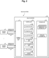
- the analysis server 10 includes a communication unit 11, a storage unit 12, and a control unit 13.
- the communication unit 11 is a communication interface with an external device.
- the communication unit 11 receives observation information from the sensing device 2 or transmits a monitoring list to the sensing device 2 via a network such as the Internet.
- the storage unit 12 stores data to be referred to when the control unit 13 executes various processes and data created by the control unit 13 executing various processes.
- the storage unit 12 stores observation information acquired from each of the sensing devices 2 or information (topology information) indicating a topology of a network created by the control unit 13.
- the control unit 13 controls the entire analysis server 10.
- the control unit 13 includes an acquisition unit 130, an estimation unit 131, an allocation unit 132, a list creation unit 133, a list transmission unit 134, an analysis unit 135, and a control processing unit 136.
- the acquisition unit 130 acquires observation information of communication from each sensing device 2.
- the acquisition unit 130 stores the acquired observation information in the storage unit 12.
- the estimation unit 131 estimates a topology of the network on the basis of the observation information acquired from each sensing device 2. That is, the estimation unit 131 estimates a disposition and connection of a router, an apparatus (for example, a SW), and a terminal (for example, a PC) of the network that is a monitoring target, and an IP address and a MAC address allocated to each device. The estimation unit 131 estimates a router via which an external terminal of the network that is a monitoring target is connected and an IP address allocated to the external terminal.
- the estimation unit 131 estimates an IP address and a MAC address of the terminal, an IP address and a MAC address of the router, and an IP address of the external terminal of the network that is a monitoring target, on the basis of a difference between pieces of observation information acquired from the respective sensing devices 2.
- the estimation unit 131 estimates a topology (for example, the topology illustrated in Fig. 1 ) of an L2 network in a subnet by using the estimation result. Details of estimation of a topology by the estimation unit 131 will be described later with reference to the drawings.
- the allocation unit 132 allocates communication that is a target for transmission of observation information from each sensing device 2 on the basis of the topology estimated by the estimation unit 131, the installation position of each sensing device 2, and the observation information of communication from each sensing device 2.
- the allocation unit 132 allocates each sensing device 2 for each piece of communication flowing through the network such that any one of the sensing devices 2 of SWs on a path of the communication transmits the observation information of the communication on the basis of the topology estimated by the estimation unit 131, the installation position of each sensing device 2, and the observation information of the communication from each sensing device 2.
- the allocation unit 132 allocates the sensing device 2A as the sensing device 2 that transmits observation information of communication from PC1 to PC5 among the sensing devices 2 (2A, 2B, and 2C) of SW1, SW2, and SW3 on the path from PC1 to PC5 illustrated in Fig. 1 .
- the list creation unit 133 allocates the sensing device 2C as the sensing device 2 that transmits observation information of communication from PC5 to PC1 among the sensing devices 2 (2A, 2B, and 2C) of SW1, SW2, and SW3 on the path from PC5 to PC1.
- the allocation unit 132 performs the above allocation process on the sensing device 2 for each piece of communication flowing through the network. Consequently, communication that is to be a target for transmission of observation information is allocated to each sensing device 2.
- the list creation unit 133 creates a monitoring list indicating communication that is a target for transmission of observation information for each sensing device 2 on the basis of the allocation result from the allocation unit 132.
- this monitoring list is information indicating a transmission source IP address related to communication that is a target for transmission of the observation information from the sensing device 2 and a transmission source IP address related to communication that is not a target for transmission.
- the monitoring list will be described in detail with reference to Fig. 3 .
- the list creation unit 133 creates a monitoring list 301 for the sensing device 2A and a monitoring list 302 for the sensing device 2B illustrated in Fig. 3 , and creates a monitoring list 303 for the sensing device 2C.
- the monitoring list 301 indicates that communication in which transmission sources are PC1 and PC2 is a target for transmission of observation information, but communication in which transmission sources are PC3, PC4, and PC5 is not a target for transmission of observation information. It is indicated that all pieces of communication in which transmission sources are not PC3, PC4, and PC5 are targets for transmission of observation information.
- the monitoring list 302 indicates that communication in which transmission sources are PC3 and PC4 is a target for transmission of observation information, but communication in which transmission sources are PC1, PC2, and PC5 is not a target for transmission of observation information. It is indicated that all pieces of communication in which transmission sources are not PC1, PC2, and PC5 are targets for transmission of observation information.
- the monitoring list 303 indicates that communication in which a transmission source is PC5 is a target for transmission of observation information, but communication in which transmission sources are PC1, PC2, PC3, and PC4 is not a target for transmission of observation information. It is indicated that all pieces of communication in which transmission sources are not PC1, PC2, PC3, and PC4 are targets for transmission of observation information.
- the sensing device 2A transmits observation information of communication from PC1 to PC3 to the analysis server 10 but does not transmit observation information of communication from PC3 to PC1 to the analysis server 10 on the basis of the monitoring list 301.
- the sensing device 2B transmits observation information of communication from PC3 to PC1 to the analysis server 10 but does not transmit observation information of communication from PC1 to PC3 to the analysis server 10 on the basis of the monitoring list 302.
- the sensing device 2C transmits observation information of communication from W2 (external terminal) to PC5 and observation information of communication from PC5 to W2 to the analysis server 10 on the basis of the monitoring list 303.
- the analysis server 10 can reduce a possibility of redundantly receiving observation information of the same communication from each sensing device 2. For example, in a case where there is only one sensing device 2 on the communication path as in the communication between W2 and PC5 illustrated in Fig. 3 , the analysis server 10 creates the monitoring list 303 in which the sensing device 2 (that is, the sensing device 2C) transmits observation information of the communication from W2 to PC5 and the communication from PC5 to W2, and transmits the monitoring list to the sensing device 2C. Consequently, the analysis server 10 can receive observation information of communication in the network that is a monitoring target without omission.
- the sensing device 2 that is, the sensing device 2C
- the list transmission unit 134 transmits the monitoring list created by the list creation unit 133 to each sensing device 2. For example, the list transmission unit 134 transmits the monitoring list 301 illustrated in Fig. 3 to the sensing device 2A, transmits the monitoring list 302 to the sensing device 2B, and transmits the monitoring list 303 to the sensing device 2C.
- the description returns to Fig. 2 .
- the analysis unit 135 analyzes communication in the network on the basis of the observation information of each piece of communication in the network acquired by the acquisition unit 130.
- the analysis unit 135 detects communication performed by an impersonated terminal by comparing a pair of the transmission source IP address and the transmission source MAC address in the observation information with a pair of an IP address and a MAC address of each terminal, router, or the like indicated in the topology information stored in the storage unit 12.
- the analysis unit 135 detects a change in the topology on the basis of the observation information of the communication acquired by the acquisition unit 130. For example, the analysis unit 135 detects the presence or absence of a change in the topology by comparing an estimated new topology with the topology stored in the storage unit 12 on the basis of the observation information acquired by the acquisition unit 130. When it is detected that there is a change in the topology, the analysis unit 135 outputs a detection result (for example, which terminal in the network has been added and which terminal has been moved).
- a detection result for example, which terminal in the network has been added and which terminal has been moved.
- a user of the analysis server 10 can ascertain that there is a possibility that an unauthorized terminal has been connected to the network and that there has been a change in the network configuration due to movement of a terminal or an apparatus.
- the control processing unit 136 controls each unit of the control unit 13. For example, in a case where the analysis unit 135 detects that there is a change in the topology of the network, when the user of the analysis server 10 determines that the change in the topology is not illegal, the control processing unit 136 instructs the allocation unit 132 to allocate communication that is a target for transmission of observation information from each sensing device 2 on the basis of the estimated new topology and the observation information.
- the list creation unit 133 reallocates communication that is a target for transmission of observation information from each sensing device 2 on the basis of the estimated new topology and the observation information.
- the list creation unit 133 recreates the monitoring list for each of the sensing devices 2 by using the result of the reallocation described above.
- the list transmission unit 134 transmits the recreated monitoring list to each sensing device 2.
- each sensing device 2 transmits observation information on the basis of the new monitoring list.
- the analysis server 10 can appropriately receive observation information from each of the sensing devices 2 even when there is a change in a network configuration.
- a case where the sensing device 2 acquires observation information from SW1, SW2, and SW3 in a network denoted by the reference numeral 401 will be described as an example.
- An arrow denoted by the reference numeral 401 indicates communication in the network.
- W1 and W2 denote external terminals
- RT denotes a router.
- the estimation unit 131 creates a list 402 indicating observation information of communication (a transmission source IP address (Src IP), a transmission source MAC address (Src MAC), a transmission destination IP address (Dst IP), and a transmission destination MAC address (Dst MAC) of the communication) via SW1, SW2, and SW3 acquired by the acquisition unit 130.
- the estimation unit 131 creates, for each MAC address, the list 403 indicating an IP address associated with the MAC address on the basis of the list 402.
- the router replaces a MAC address of an IP address of a packet that is a routing target with a MAC address allocated to the router. Therefore, a plurality of IP addresses are associated with the MAC address allocated to the router.
- the MAC address of the router is associated with a plurality of IP addresses. Therefore, the estimation unit 131 estimates R1 and R2, which are MAC addresses associated with a plurality of IP addresses in the list 403, as MAC addresses of the router.
- the estimation unit 131 creates a list 501 indicating a pair of (a transmission source MAC address (Src MAC) and a transmission destination MAC address (Dst MAC)) corresponding to the pair.
- the transmission source MAC addresses of the other pairs can be considered as a MAC address of an exit IF (interface) of the router (refer to the reference numeral 502).
- pairs of (transmission source MAC address, transmission destination MAC address) for (PC1, PC5) in the list 501 are (PC1, R1) and (R3, PC5).
- the transmission destination MAC address (R1) in the pair of (PC1, R1) is a MAC address of the router estimated in (Estimation 1 of MAC address of router) described in Fig. 4 .
- the transmission source MAC address (R3) in another pair (R3, PC5) is not estimated as a MAC address of the router in (Estimation 1 of MAC address of router) described in Fig. 4 , but can be considered as a MAC address of the exit IF of the router (refer to the reference numeral 502).
- the estimation unit 131 estimates R3 in the above pair of (R3, PC5) as the MAC address of the router (refer to (1) in the list 501). By performing the above process, the estimation unit 131 can also estimate the MAC address of the router that cannot be estimated in (Estimation 1 of MAC address of router) described with reference to Fig. 4 .
- the pair of (transmission source IP address, transmission destination IP address) can be considered to be a pair with an IP address of the external terminal (refer to the reference numeral 502 and (2) in the list 501).
- each of the pairs of IP addresses of (PC1, W1) and (PC1, W2) in the list 501 can be considered as a pair indicating communication with the external terminal. Therefore, the estimation unit 131 estimates W1 and W2 as IP addresses of the external terminals.
- the estimation unit 131 estimates a topology of the network by using the MAC address of the router and the IP address of the external terminal estimated through the above process.
- the estimation unit 131 estimates the topology of the network indicated by the reference numeral 602 by using observation information (transmission source IP addresses (Src IP), transmission source MAC addresses (Src MAC), transmission destination IP addresses (Dst IP), and transmission destination MAC addresses (Dst MAC) of communication) of SW1, SW2, and SW3 denoted by the reference numeral 601 in Fig. 6 and the MAC address of the router and the IP address of the external terminal estimated through the above process.
- observation information transmission source IP addresses (Src IP), transmission source MAC addresses (Src MAC), transmission destination IP addresses (Dst IP), and transmission destination MAC addresses (Dst MAC) of communication
- SW1, SW2, and SW3 denoted by the reference numeral 601 in Fig. 6 and the MAC address of the router and the IP address of the external terminal estimated through the above process.
- the allocation unit 132 performs allocation for each piece of communication flowing through the network such that any one of the sensing devices 2 capable of transmitting observation information of the communication transmits the observation information of the communication.
- the allocation unit 132 allocates communication of PC1 and PC2 to the sensing device 2 of SW1, allocates communication of PC3 and PC4 to the sensing device 2 of SW2, and allocates communication of PC5 to the sensing device 2 of SW3.
- the list creation unit 133 creates monitoring lists 603 to 605 on the basis of the allocation results. That is, the list creation unit 133 creates the monitoring list 603 for the sensing devices 2 of SW1, creates the monitoring list 604 for the sensing devices 2 of SW2, and creates the monitoring list 605 for the sensing devices 2 of SW3. Thereafter, the list transmission unit 134 transmits the monitoring lists 603 to 605 to the target sensing devices 2. Each sensing device 2 transmits observation information of communication indicated in the received monitoring list to the analysis server 10.
- the analysis server 10 can appropriately receive observation information of communication in the network from each sensing device 2.
- the acquisition unit 130 of the analysis server 10 transmits an instruction for transmitting observation information of communication to each sensing device 2 (S1).
- Each of the sensing devices 2 creates observation information of communication via the SW in the network that is a monitoring target on the basis of the above instruction, and transmits the observation information to the analysis server 10 (S2).
- the estimation unit 131 of the analysis server 10 creates a list of communication observed by the SW (refer to, for example, the list 402 in Fig. 4 ) for each apparatus (for example, the SW) in the network that is a monitoring target on the basis of the observation information of communication transmitted from each sensing device 2.
- the estimation unit 131 estimates a MAC address of the router in the network that is a monitoring target according to the method described in above (Estimation 1 of MAC address of router) (S3: Router Estimation 1).
- the estimation unit 131 estimates the MAC address of the router according to the method described in above (Estimation 2 of MAC address of router) (S4: Router Estimation 2). Consequently, the estimation unit 131 can also estimate the MAC address of the router that cannot be estimated in S3.
- the estimation unit 131 estimates an IP address of the external terminal according to the method described in the above (Estimation of external terminal) on the basis of the created list (S5: Estimation of external terminal).
- the estimation unit 131 records an estimation result of the MAC address of the router and an estimation result of the IP address of the external terminal obtained through the above process in the above list (refer to the list 601 in Fig. 6 ).
- the estimation unit 131 executes the processes in and after S4 again.
- the estimation unit 131 estimates a topology of the network on the basis of the above list (S7).
- the allocation unit 132 allocates communication that is a target for transmission of the observation information from each sensing device 2 on the basis of the estimation result of the topology in S7.
- the list creation unit 133 creates a monitoring list for each sensing device 2 on the basis of the allocation result (S8). Thereafter, the list transmission unit 134 transmits the monitoring list for each sensing device 2 to each sensing device 2.
- each sensing device 2 starts monitoring communication on the basis of the transmitted monitoring list (S9). If the observed communication is a target for transmission of the observation information indicated in the monitoring list (Yes in S10), each sensing device 2 transmits the observation information of the communication to the analysis server 10. On the other hand, if the observed communication is not a target for transmission (No in S10), each sensing device 2 continues monitoring (S11), and returns to S10.
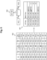
- the analysis unit 135 specifies an apparatus (for example, a PC) included in the observation information from the estimation result of the topology (topology information) in S7 (S13).
- the analysis unit 135 performs a communication abnormality detection process by using information regarding the apparatus specified in S13 (S14).
- the analysis unit 135 executes the processes in the above S13 and S14 each time the observation information is received from the sensing device 2.
- the analysis unit 135 specifies an apparatus ID and a current installation location (NW configuration) of each apparatus from a device ID of the sensing device 2, an apparatus IP (an IP address of the apparatus), and an apparatus MAC (a MAC address of the apparatus) indicated in the observation information received in S12 in Fig. 7 (S131 in Fig. 8 ).
- the analysis unit 135 determines whether there is a difference between the NW configuration specified in S131 and the topology information stored in the storage unit 12 (S132).
- the analysis unit 135 determines that there is a difference between the NW configuration specified in S131 and the topology information stored in the storage unit 12 (Yes in S132), information regarding the difference is output via the communication unit 11 (S133). Consequently, the user of the analysis server 10 can ascertain that the configuration of the network that is a monitoring target has been changed. Thereafter, the analysis server 10 receives input of a determination result regarding whether the configuration change of the network is a normal configuration change from the user.
- the analysis unit 135 receives an input indicating that the configuration change of the network is a normal configuration change from the user (Yes in S134)
- the topology information is updated on the basis of the NW configuration specified in S131 (S135).
- the analysis unit 135 performs a process of detecting communication details on the basis of the topology information updated in S135 and the observation information received in S12 in Fig. 7 (S141). For example, in a case where the pair of the IP address and the MAC address of the terminal indicated in the observation information received in S12 in Fig. 7 does not match the pair of the IP address and the MAC address indicated in the topology information, the analysis unit 135 detects the communication indicated in the observation information as communication performed by an impersonated terminal.
- the analysis unit 135 detects an abnormality (for example, communication performed by an impersonated terminal) in the communication details through the detection process in S141 (Yes in S142), a notification indicating that the abnormality has been detected is sent through the communication unit 11 (S143: abnormality detection notification). Thereafter, the user handles the abnormality in the network on the basis of the notification.
- an abnormality for example, communication performed by an impersonated terminal
- the process proceeds to S8 in Fig. 7 . That is, on the basis of the topology information updated in S135, the allocation unit 132 reallocates communication that is a target for transmission of the observation information from each sensing device 2.
- the list creation unit 133 recreates a monitoring list for each of the sensing devices 2 on the basis of the reallocation result (S8 in Fig. 7 ). Thereafter, the list transmission unit 134 transmits the recreated monitoring list to each sensing device 2.
- the process returns to S12 in Fig. 7 . That is, the analysis server 10 waits for arrival of the observation information from the sensing device 2.
- the analysis unit 135 outputs information regarding a difference between the NW configuration specified in S131 in Fig. 8 and the topology information stored in the storage unit 12 (S133), and in a case where it is determined by the user that some kind of abnormality has occurred in the configuration change of the network (No in S134), the user handles the abnormality in the network.
- each sensing device 2 is allocated such that the sensing device 2 of any one SW on a path of communication transmits observation information of the communication by using the estimated topology. Consequently, the analysis server 10 can reduce redundant transmission of the observation information from each sensing device 2.
- the sensing device 2 transmits observation information of the communication to the analysis server 10. That is, the sensing device 2C in Fig. 3 transmits observation information for W2 to PC5 and observation information for PC5 to W2 to the analysis server 10. Consequently, the analysis server 10 can receive observation information of communication in the network that is a monitoring target without omission.
- the analysis server 10 can estimate an L2 topology by comparing observation information from each of the sensing devices 2 (sensing devices 2A, 2B, and 2C). For example, the analysis server 10 can estimate the L2 topology by comparing observation information according to the methods described in (Estimation 1 of MAC address of router) and (Estimation 2 of MAC address of router).
- the analysis server 10 can estimate an IP address and a MAC address of the router and an IP address of the external terminal by comparing observation information according to the methods described in (Estimation 1 of MAC address of router) and (Estimation 2 of MAC address of router). As a result, when the analysis server 10 detects an impersonated terminal by using the IP address and the MAC address indicated in the observation information from each sensing device 2, it is possible to reduce erroneous detection.
- a topology can be estimated by the same algorithm as described above.
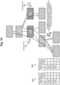
- PC1 and PC2 illustrated in Fig. 10 are terminals of a network different from the network to which SW1 belongs, but the sensing device 2A of SW1 always observes communication in which PC1 and PC2 are transmission sources or transmission destinations. From this, the analysis server 10 estimates that PC1 and PC2 are under control of SW1. The analysis server 10 estimates, for example, the topology illustrated in Fig. 10 as a topology of the network.
- the analysis server 10 creates a monitoring list denoted by the reference numeral 1001 as a monitoring list for the sensing device 2A of SW1, for example, by using the estimation result of the topology.
- the analysis server 10 creates, for example, a monitoring list denoted by the reference numeral 1002 as a monitoring list for the sensing device 2B of SW2.
- the analysis server 10 acquires observation information transmitted from the sensing devices 2A and 2B on the basis of the monitoring list.
- the analysis server 10 can acquire observation information of communication between PC1 and PC2.
- the analysis server 10 can also monitor communication between terminals in a complicated network such as a network in which routers are hierarchically installed as illustrated in Fig. 10 .
- a complicated network such as a network in which routers are hierarchically installed as illustrated in Fig. 10 .
- communication of terminals outside the local network such as PC1 and PC2 in Fig. 10
- communication of terminals outside the local network can be monitored.
- the analysis unit 135 of the analysis server 10 may output information regarding a monitoring location insufficient for monitoring communication in the network on the basis of the estimated topology of the network and the information regarding the installation location of the sensing device 2 in the network.
- the analysis unit 135 recommends installing a new sensing device 2 at a location (for example, RT2) where the communication between PC1 and PC2 can be monitored. Consequently, the user of the analysis server 10 can ascertain a location where the sensing device 2 is added in order to monitor each piece of communication in the network without omission.
- a location for example, RT2
- the analysis server 10 it is possible to estimate a topology that does not contradict an actual network configuration on the basis of the observation information transmitted from each sensing device 2. For example, there is a possibility that there is a location that the analysis server 10 cannot accurately estimate a network configuration depending on a case where observation information is insufficient or an installation location of the sensing device 2, but sensing (acquisition of observation information of communication from each sensing device 2) can be performed without any problem.
- At least one sensing device 2 transmits observation information of each piece of communication, and thus missing of the observation information does not occur.
- the analysis server 10 can detect new observation information or a network configuration change, connection of an unauthorized apparatus or movement of an apparatus can be detected. After detecting the configuration change of the network, the analysis server 10 can update the topology information and perform a communication detection process on the basis of the updated topology information and the observation information of the communication (refer to S141 in Fig. 7 ). Consequently, the analysis server 10 can appropriately perform a communication detection process.
- the analysis server 10 After detecting the configuration change of the network, the analysis server 10 can recreate and transmit the monitoring list for each sensing device 2 on the basis of the updated topology information. Consequently, the analysis server 10 can appropriately receive observation information from each sensing device 2.
- the network that is a monitoring target of the analysis server 10 may be a network configured by a white box switch (WB SW) having the function of the sensing device 2 ( Fig. 11 ).
- the analysis server 10 transmits a monitoring list to each WB SW.
- Each WB SW transmits observation information of communication to the analysis server 10 on the basis of the monitoring list transmitted from the analysis server 10.
- the analysis server 10 monitors the communication in the network on the basis of the observation information of the communication transmitted from each WB SW.
- each constituent of each unit illustrated in the drawings is functionally conceptual and does not necessarily need to be physically configured as illustrated in the drawings.
- a specific form of distribution and integration of individual devices is not limited to the illustrated form, and all or some of the devices may be functionally or physically distributed and integrated in any unit according to various loads, usage conditions, and the like. All or some of the processing functions performed in the respective devices may be realized by a CPU and a program to be executed by the CPU or may be realized as hardware by wired logic.
- all or some of the processes described as being automatically performed may be manually performed, or all or some of the processes described as being manually performed may be automatically performed according to a known method.
- the processing procedure, the control procedure, the specific name, and the information including various types of data and parameters that are illustrated in the document and the drawings can be freely changed unless otherwise specified.
- the analysis server 10 can be implemented by installing a program as package software or online software in a desired computer. For example, by causing an information processing apparatus to execute the above program, the information processing apparatus can be caused to function as the analysis server 10.
- the information processing apparatus mentioned here includes a desktop or a laptop personal computer.
- the information processing apparatus also includes a mobile communication terminal such as a smartphone, a mobile phone, or a personal handy-phone system (PHS) and a terminal such as a personal digital assistant (PDA).
- PHS personal handy-phone system
- PDA personal digital assistant
- the analysis server 10 may also be implemented as a server apparatus that uses a terminal apparatus used by a user as a client and provides the client with a service related to the above process.
- the server apparatus may be implemented as a web server or may be implemented as a cloud that provides a service related to the above process by outsourcing.
- FIG. 12 illustrates an example of a computer that executes an analysis program.
- a computer 1000 includes, for example, a memory 1010 and a CPU 1020.
- the computer 1000 also includes a hard disk drive interface 1030, a disk drive interface 1040, a serial port interface 1050, a video adapter 1060, and a network interface 1070. These units are connected to each other via a bus 1080.
- the memory 1010 includes a read only memory (ROM) 1011 and a random access memory (RAM) 1012.
- the ROM 1011 stores, for example, a boot program such as a basic input output system (BIOS).
- BIOS basic input output system
- the hard disk drive interface 1030 is connected to a hard disk drive 1090.
- the disk drive interface 1040 is connected to a disk drive 1100.
- a removable storage medium such as a magnetic disk or an optical disc is inserted into the disk drive 1100.
- the serial port interface 1050 is connected to, for example, a mouse 1110 and a keyboard 1120.
- the video adapter 1060 is connected with, for example, a display 1130.
- the hard disk drive 1090 stores, for example, an OS 1091, an application program 1092, a program module 1093, and program data 1094. That is, a program that defines each process executed by the analysis server 10 is implemented as the program module 1093 in which a computer executable code is described.
- the program module 1093 is stored in, for example, the hard disk drive 1090.
- the program module 1093 for executing processes similar to those of the functional configuration in the analysis server 10 is stored in the hard disk drive 1090.
- the hard disk drive 1090 may be replaced with a solid state drive (SSD).
- Data to be used in the processes of the above embodiment is stored in, for example, the memory 1010 or the hard disk drive 1090 as the program data 1094.
- the CPU 1020 reads the program module 1093 or the program data 1094 stored in the memory 1010 or the hard disk drive 1090 to the RAM 1012 as necessary and executes the program module 1093 or the program data 1094.
- the program module 1093 or the program data 1094 is not limited to being stored in the hard disk drive 1090, and may be stored in, for example, a removable storage medium and read by the CPU 1020 via the disk drive 1100 or the like. Alternatively, the program module 1093 and the program data 1094 may be stored in another computer connected via a network (local area network (LAN), wide area network (WAN), or the like). The program module 1093 and the program data 1094 may be read by the CPU 1020 from another computer via the network interface 1070.
- LAN local area network
- WAN wide area network
Landscapes
- Engineering & Computer Science (AREA)
- Computer Networks & Wireless Communication (AREA)
- Signal Processing (AREA)
- Data Exchanges In Wide-Area Networks (AREA)
- Analysing Materials By The Use Of Radiation (AREA)
- Investigating Or Analysing Biological Materials (AREA)
Applications Claiming Priority (1)
| Application Number | Priority Date | Filing Date | Title |
|---|---|---|---|
| PCT/JP2021/021635 WO2022259335A1 (ja) | 2021-06-07 | 2021-06-07 | 分析装置、分析方法、および、分析プログラム |
Publications (2)
| Publication Number | Publication Date |
|---|---|
| EP4333376A1 true EP4333376A1 (de) | 2024-03-06 |
| EP4333376A4 EP4333376A4 (de) | 2025-02-26 |
Family
ID=84425030
Family Applications (1)
| Application Number | Title | Priority Date | Filing Date |
|---|---|---|---|
| EP21945014.5A Pending EP4333376A4 (de) | 2021-06-07 | 2021-06-07 | Analysevorrichtung, analyseverfahren und analyseprogramm |
Country Status (6)
| Country | Link |
|---|---|
| US (1) | US12615197B2 (de) |
| EP (1) | EP4333376A4 (de) |
| JP (1) | JP7622838B2 (de) |
| CN (1) | CN117546454A (de) |
| AU (1) | AU2021449885B2 (de) |
| WO (1) | WO2022259335A1 (de) |
Family Cites Families (16)
| Publication number | Priority date | Publication date | Assignee | Title |
|---|---|---|---|---|
| US20060026680A1 (en) * | 2004-07-29 | 2006-02-02 | Zakas Phillip H | System and method of characterizing and managing electronic traffic |
| JP4523444B2 (ja) * | 2005-02-10 | 2010-08-11 | 富士通株式会社 | 通信ネットワークにおける障害の原因を特定する障害管理装置および方法 |
| US8811224B2 (en) * | 2006-05-30 | 2014-08-19 | McAfee Ireland Holdings, Limited | Method and system for determining physical connectivity in a dynamic network |
| JP4809880B2 (ja) | 2008-09-09 | 2011-11-09 | 日本電信電話株式会社 | ネットワークトポロジ推定システム、ネットワークトポロジ推定方法及び記録媒体 |
| JP5407883B2 (ja) * | 2010-01-14 | 2014-02-05 | 富士通株式会社 | トポロジーツリー作成装置、プログラム、及び方法 |
| JP5641062B2 (ja) * | 2011-01-31 | 2014-12-17 | 富士通株式会社 | トラフィックデータ統合方法および装置 |
| US9219650B2 (en) * | 2011-03-07 | 2015-12-22 | Hitachi, Ltd. | Network management apparatus, network management method, and network management system |
| US9397895B2 (en) * | 2011-12-13 | 2016-07-19 | Viavi Solutions Inc. | Method and system for collecting topology information |
| US10355937B2 (en) * | 2015-03-09 | 2019-07-16 | Oath Inc. | Systems and methods for determining a topology of a network comprising a plurality of intermediary devices and paths |
| US10536357B2 (en) * | 2015-06-05 | 2020-01-14 | Cisco Technology, Inc. | Late data detection in data center |
| CN106201827B (zh) * | 2016-07-13 | 2018-11-27 | 东软集团股份有限公司 | 监控数据采集方法及系统 |
| GB201704931D0 (en) * | 2017-03-28 | 2017-05-10 | Indigovision Ltd | Monitoring devices and methods for IP surveillance networks |
| TWI664838B (zh) | 2017-12-14 | 2019-07-01 | 財團法人工業技術研究院 | 在一網路中監測傳輸量的方法及裝置 |
| JP7081445B2 (ja) * | 2018-11-05 | 2022-06-07 | 富士通株式会社 | ネットワーク制御装置、及び、ネットワーク制御方法 |
| CN110474816B (zh) * | 2019-09-24 | 2020-07-03 | 珠海格力电器股份有限公司 | 网络拓扑发现的方法及存储介质 |
| JP7417395B2 (ja) | 2019-10-01 | 2024-01-18 | アズビル株式会社 | 不正検出装置および不正検出方法 |
-
2021
- 2021-06-07 WO PCT/JP2021/021635 patent/WO2022259335A1/ja not_active Ceased
- 2021-06-07 EP EP21945014.5A patent/EP4333376A4/de active Pending
- 2021-06-07 JP JP2023527178A patent/JP7622838B2/ja active Active
- 2021-06-07 CN CN202180099042.3A patent/CN117546454A/zh active Pending
- 2021-06-07 US US18/565,143 patent/US12615197B2/en active Active
- 2021-06-07 AU AU2021449885A patent/AU2021449885B2/en active Active
Also Published As
| Publication number | Publication date |
|---|---|
| US20240205117A1 (en) | 2024-06-20 |
| EP4333376A4 (de) | 2025-02-26 |
| CN117546454A (zh) | 2024-02-09 |
| JPWO2022259335A1 (de) | 2022-12-15 |
| WO2022259335A1 (ja) | 2022-12-15 |
| AU2021449885A1 (en) | 2023-11-23 |
| US12615197B2 (en) | 2026-04-28 |
| JP7622838B2 (ja) | 2025-01-28 |
| AU2021449885B2 (en) | 2024-10-24 |
Similar Documents
| Publication | Publication Date | Title |
|---|---|---|
| US11461086B2 (en) | Methods and apparatus for safe and smart distribution of software patches | |
| EP3281360B1 (de) | Virtualisierte netzwerkfunktionsüberwachung | |
| US8191069B2 (en) | Method of monitoring performance of virtual computer and apparatus using the method | |
| US11556369B2 (en) | Virtual machine deployment method and OMM virtual machine | |
| CN108777640B (zh) | 一种服务器探测方法、装置、系统及存储介质 | |
| JP2011258098A (ja) | 仮想計算機システム、仮想計算機システムの監視方法及びネットワーク装置 | |
| CN111064781A (zh) | 多容器集群监控数据的采集方法、装置及电子设备 | |
| US20150326658A1 (en) | Apparatus and method for controlling virtual machine migrations based on flow information | |
| JPWO2011108553A1 (ja) | 構成情報管理サーバ、構成情報管理方法、及び構成情報管理用プログラム | |
| US20170317908A1 (en) | Server group and group manager with support for location-based operations | |
| AU2019277439B2 (en) | Abnormality detection apparatus, abnormality detection method, and abnormality detection program | |
| US7698417B2 (en) | Optimized performance counter monitoring | |
| AU2021449885B2 (en) | Analysis device, analysis method, and analysis program | |
| US11353855B1 (en) | Configuring and deploying gateway connectors and workflows for data sources at client networks | |
| US20220086088A1 (en) | Identification device and identification program | |
| US20210377129A1 (en) | Network building apparatus, network building method, non-transitory computer readable medium storing program | |
| WO2021024327A1 (ja) | 転送装置、通信システム、転送方法及び転送プログラム | |
| US20120291115A1 (en) | Method and apparatus for dynamic host operating system firewall configuration | |
| CN115242704A (zh) | 网络拓扑数据更新方法、装置和电子设备 | |
| US20170286181A1 (en) | Deployment and execution of sensing and computational tasks in a network of computing devices | |
| JP2021089685A (ja) | セキュリティリスク軽減方法及びシステム | |
| CN119544287B (zh) | 一种通信流量异常分析方法、装置、终端及介质 | |
| CN117014353B (zh) | 一种拨测策略生成的方法、装置、存储介质和计算设备集群 | |
| US8799919B2 (en) | Load balancing management of newly discovered data processing systems using peer control points | |
| US20250330408A1 (en) | Underlay-aware routing in sd-wan networks |
Legal Events
| Date | Code | Title | Description |
|---|---|---|---|
| STAA | Information on the status of an ep patent application or granted ep patent |
Free format text: STATUS: THE INTERNATIONAL PUBLICATION HAS BEEN MADE |
|
| PUAI | Public reference made under article 153(3) epc to a published international application that has entered the european phase |
Free format text: ORIGINAL CODE: 0009012 |
|
| STAA | Information on the status of an ep patent application or granted ep patent |
Free format text: STATUS: REQUEST FOR EXAMINATION WAS MADE |
|
| 17P | Request for examination filed |
Effective date: 20231124 |
|
| AK | Designated contracting states |
Kind code of ref document: A1 Designated state(s): AL AT BE BG CH CY CZ DE DK EE ES FI FR GB GR HR HU IE IS IT LI LT LU LV MC MK MT NL NO PL PT RO RS SE SI SK SM TR |
|
| DAV | Request for validation of the european patent (deleted) | ||
| DAX | Request for extension of the european patent (deleted) | ||
| REG | Reference to a national code |
Ref country code: DE Ref legal event code: R079 Free format text: PREVIOUS MAIN CLASS: H04L0012000000 Ipc: H04L0041120000 |
|
| A4 | Supplementary search report drawn up and despatched |
Effective date: 20250124 |
|
| RIC1 | Information provided on ipc code assigned before grant |
Ipc: H04L 43/12 20220101ALI20250120BHEP Ipc: H04L 43/028 20220101ALI20250120BHEP Ipc: H04L 43/026 20220101ALI20250120BHEP Ipc: H04L 41/12 20220101AFI20250120BHEP |
|
| STAA | Information on the status of an ep patent application or granted ep patent |
Free format text: STATUS: EXAMINATION IS IN PROGRESS |
|
| RAP3 | Party data changed (applicant data changed or rights of an application transferred) |
Owner name: NTT, INC. |
|
| 17Q | First examination report despatched |
Effective date: 20250919 |