EP4333255A1 - Portable power supply with bidirectional charging and passthrough - Google Patents
Portable power supply with bidirectional charging and passthrough Download PDFInfo
- Publication number
- EP4333255A1 EP4333255A1 EP23190041.6A EP23190041A EP4333255A1 EP 4333255 A1 EP4333255 A1 EP 4333255A1 EP 23190041 A EP23190041 A EP 23190041A EP 4333255 A1 EP4333255 A1 EP 4333255A1
- Authority
- EP
- European Patent Office
- Prior art keywords
- power
- switch
- battery core
- power supply
- input interface
- Prior art date
- Legal status (The legal status is an assumption and is not a legal conclusion. Google has not performed a legal analysis and makes no representation as to the accuracy of the status listed.)
- Pending
Links
Images






Classifications
-
- H—ELECTRICITY
- H02—GENERATION; CONVERSION OR DISTRIBUTION OF ELECTRIC POWER
- H02J—ELECTRIC POWER NETWORKS; CIRCUIT ARRANGEMENTS OR SYSTEMS FOR SUPPLYING OR DISTRIBUTING ELECTRIC POWER; SYSTEMS FOR STORING ELECTRIC ENERGY
- H02J9/00—Circuit arrangements for emergency or stand-by power supply, e.g. for emergency lighting
- H02J9/04—Circuit arrangements for emergency or stand-by power supply, e.g. for emergency lighting in which the distribution system is disconnected from the normal source and connected to a standby source
- H02J9/06—Circuit arrangements for emergency or stand-by power supply, e.g. for emergency lighting in which the distribution system is disconnected from the normal source and connected to a standby source with automatic change-over, e.g. UPS systems
- H02J9/062—Circuit arrangements for emergency or stand-by power supply, e.g. for emergency lighting in which the distribution system is disconnected from the normal source and connected to a standby source with automatic change-over, e.g. UPS systems for AC powered loads
-
- H—ELECTRICITY
- H02—GENERATION; CONVERSION OR DISTRIBUTION OF ELECTRIC POWER
- H02J—ELECTRIC POWER NETWORKS; CIRCUIT ARRANGEMENTS OR SYSTEMS FOR SUPPLYING OR DISTRIBUTING ELECTRIC POWER; SYSTEMS FOR STORING ELECTRIC ENERGY
- H02J9/00—Circuit arrangements for emergency or stand-by power supply, e.g. for emergency lighting
- H02J9/04—Circuit arrangements for emergency or stand-by power supply, e.g. for emergency lighting in which the distribution system is disconnected from the normal source and connected to a standby source
- H02J9/06—Circuit arrangements for emergency or stand-by power supply, e.g. for emergency lighting in which the distribution system is disconnected from the normal source and connected to a standby source with automatic change-over, e.g. UPS systems
-
- H—ELECTRICITY
- H02—GENERATION; CONVERSION OR DISTRIBUTION OF ELECTRIC POWER
- H02M—APPARATUS FOR CONVERSION BETWEEN AC AND AC, BETWEEN AC AND DC, OR BETWEEN DC AND DC, AND FOR USE WITH MAINS OR SIMILAR POWER SUPPLY SYSTEMS; CONVERSION OF DC OR AC INPUT POWER INTO SURGE OUTPUT POWER; CONTROL OR REGULATION THEREOF
- H02M1/00—Details of apparatus for conversion
- H02M1/0067—Converter structures employing plural converter units, other than for parallel operation of the units on a single load
- H02M1/007—Plural converter units in cascade
-
- H—ELECTRICITY
- H02—GENERATION; CONVERSION OR DISTRIBUTION OF ELECTRIC POWER
- H02M—APPARATUS FOR CONVERSION BETWEEN AC AND AC, BETWEEN AC AND DC, OR BETWEEN DC AND DC, AND FOR USE WITH MAINS OR SIMILAR POWER SUPPLY SYSTEMS; CONVERSION OF DC OR AC INPUT POWER INTO SURGE OUTPUT POWER; CONTROL OR REGULATION THEREOF
- H02M1/00—Details of apparatus for conversion
- H02M1/44—Circuits or arrangements for compensating for electromagnetic interference in converters or inverters
-
- H—ELECTRICITY
- H02—GENERATION; CONVERSION OR DISTRIBUTION OF ELECTRIC POWER
- H02M—APPARATUS FOR CONVERSION BETWEEN AC AND AC, BETWEEN AC AND DC, OR BETWEEN DC AND DC, AND FOR USE WITH MAINS OR SIMILAR POWER SUPPLY SYSTEMS; CONVERSION OF DC OR AC INPUT POWER INTO SURGE OUTPUT POWER; CONTROL OR REGULATION THEREOF
- H02M3/00—Conversion of DC power input into DC power output
- H02M3/01—Resonant DC/DC converters
-
- H—ELECTRICITY
- H02—GENERATION; CONVERSION OR DISTRIBUTION OF ELECTRIC POWER
- H02M—APPARATUS FOR CONVERSION BETWEEN AC AND AC, BETWEEN AC AND DC, OR BETWEEN DC AND DC, AND FOR USE WITH MAINS OR SIMILAR POWER SUPPLY SYSTEMS; CONVERSION OF DC OR AC INPUT POWER INTO SURGE OUTPUT POWER; CONTROL OR REGULATION THEREOF
- H02M3/00—Conversion of DC power input into DC power output
- H02M3/22—Conversion of DC power input into DC power output with intermediate conversion into AC
- H02M3/24—Conversion of DC power input into DC power output with intermediate conversion into AC by static converters
- H02M3/28—Conversion of DC power input into DC power output with intermediate conversion into AC by static converters using discharge tubes with control electrode or semiconductor devices with control electrode to produce the intermediate AC
- H02M3/325—Conversion of DC power input into DC power output with intermediate conversion into AC by static converters using discharge tubes with control electrode or semiconductor devices with control electrode to produce the intermediate AC using devices of a triode or a transistor type requiring continuous application of a control signal
- H02M3/335—Conversion of DC power input into DC power output with intermediate conversion into AC by static converters using discharge tubes with control electrode or semiconductor devices with control electrode to produce the intermediate AC using devices of a triode or a transistor type requiring continuous application of a control signal using semiconductor devices only
- H02M3/33569—Conversion of DC power input into DC power output with intermediate conversion into AC by static converters using discharge tubes with control electrode or semiconductor devices with control electrode to produce the intermediate AC using devices of a triode or a transistor type requiring continuous application of a control signal using semiconductor devices only having several active switching elements
- H02M3/33573—Full-bridge at primary side of an isolation transformer
-
- H—ELECTRICITY
- H02—GENERATION; CONVERSION OR DISTRIBUTION OF ELECTRIC POWER
- H02M—APPARATUS FOR CONVERSION BETWEEN AC AND AC, BETWEEN AC AND DC, OR BETWEEN DC AND DC, AND FOR USE WITH MAINS OR SIMILAR POWER SUPPLY SYSTEMS; CONVERSION OF DC OR AC INPUT POWER INTO SURGE OUTPUT POWER; CONTROL OR REGULATION THEREOF
- H02M7/00—Conversion of AC power input into DC power output; Conversion of DC power input into AC power output
- H02M7/42—Conversion of DC power input into AC power output without possibility of reversal
- H02M7/44—Conversion of DC power input into AC power output without possibility of reversal by static converters
- H02M7/48—Conversion of DC power input into AC power output without possibility of reversal by static converters using discharge tubes with control electrode or semiconductor devices with control electrode
- H02M7/53—Conversion of DC power input into AC power output without possibility of reversal by static converters using discharge tubes with control electrode or semiconductor devices with control electrode using devices of a triode or transistor type requiring continuous application of a control signal
- H02M7/537—Conversion of DC power input into AC power output without possibility of reversal by static converters using discharge tubes with control electrode or semiconductor devices with control electrode using devices of a triode or transistor type requiring continuous application of a control signal using semiconductor devices only, e.g. single switched pulse inverters
-
- H—ELECTRICITY
- H02—GENERATION; CONVERSION OR DISTRIBUTION OF ELECTRIC POWER
- H02M—APPARATUS FOR CONVERSION BETWEEN AC AND AC, BETWEEN AC AND DC, OR BETWEEN DC AND DC, AND FOR USE WITH MAINS OR SIMILAR POWER SUPPLY SYSTEMS; CONVERSION OF DC OR AC INPUT POWER INTO SURGE OUTPUT POWER; CONTROL OR REGULATION THEREOF
- H02M7/00—Conversion of AC power input into DC power output; Conversion of DC power input into AC power output
- H02M7/66—Conversion of AC power input into DC power output; Conversion of DC power input into AC power output with possibility of reversal
- H02M7/68—Conversion of AC power input into DC power output; Conversion of DC power input into AC power output with possibility of reversal by static converters
- H02M7/72—Conversion of AC power input into DC power output; Conversion of DC power input into AC power output with possibility of reversal by static converters using discharge tubes with control electrode or semiconductor devices with control electrode
- H02M7/79—Conversion of AC power input into DC power output; Conversion of DC power input into AC power output with possibility of reversal by static converters using discharge tubes with control electrode or semiconductor devices with control electrode using devices of a triode or transistor type requiring continuous application of a control signal
- H02M7/797—Conversion of AC power input into DC power output; Conversion of DC power input into AC power output with possibility of reversal by static converters using discharge tubes with control electrode or semiconductor devices with control electrode using devices of a triode or transistor type requiring continuous application of a control signal using semiconductor devices only
-
- H—ELECTRICITY
- H02—GENERATION; CONVERSION OR DISTRIBUTION OF ELECTRIC POWER
- H02J—ELECTRIC POWER NETWORKS; CIRCUIT ARRANGEMENTS OR SYSTEMS FOR SUPPLYING OR DISTRIBUTING ELECTRIC POWER; SYSTEMS FOR STORING ELECTRIC ENERGY
- H02J7/00—Circuit arrangements for charging or discharging batteries or for supplying loads from batteries
- H02J7/02—Circuit arrangements for charging or discharging batteries or for supplying loads from batteries for charging batteries from AC mains by converters
-
- H—ELECTRICITY
- H02—GENERATION; CONVERSION OR DISTRIBUTION OF ELECTRIC POWER
- H02J—ELECTRIC POWER NETWORKS; CIRCUIT ARRANGEMENTS OR SYSTEMS FOR SUPPLYING OR DISTRIBUTING ELECTRIC POWER; SYSTEMS FOR STORING ELECTRIC ENERGY
- H02J7/00—Circuit arrangements for charging or discharging batteries or for supplying loads from batteries
- H02J7/80—Circuit arrangements for charging or discharging batteries or for supplying loads from batteries including monitoring or indicating arrangements
- H02J7/82—Control of state of charge [SOC]
- H02J7/825—Detection of fully charged condition
Definitions
- Embodiments herein relate to portable power supplies.
- Portable power supplies described herein include an alternating current (“AC) power input interface, an AC power output interface, a direct current (“DC”) power output interface, and a battery core configured to provide DC power to the DC power output interface.
- the power supply further includes at least one switch including a first switch, a second switch, and a third switch.
- the first switch is electrically connected between the AC power input interface and the battery core.
- the second switch is electrically connected between the AC power input interface and the AC power output interface.
- the third switch is electrically connected between the battery core and the AC power output interface.
- the power supply also includes a controller configured to control the at least one switch to selectively provide an AC power output to the AC power output interface based on power received from either the AC power input interface or the battery core.
- the portable power supplies described herein further include an electromagnetic interference (“EMI”) filter electrically connected between the AC power input and the first switch and a voltage converter electrically connected between the first switch and the battery core.
- EMI electromagnetic interference
- the portable power supplies described herein further include an output filter including an inductor and a capacitor, the output filter electrically connected between the voltage converter and the AC power output interface.
- the portable power supplies described herein further include an inductor-capacitor-inductor (“LCL”) filter electrically connected between the first switch and the voltage converter.
- LCD inductor-capacitor-inductor
- the at least one switch further includes a second switch and a third switch, the second switch is electrically connected between the AC power input interface and the AC power output interface, and the third switch is electrically connected between the battery core and the AC power output interface.
- the portable power supplies described herein further include an electromagnetic interference (“EMI”) filter electrically connected between the AC power input and the first switch, and a voltage converter electrically connected between the first switch, the third switch, and the battery core.
- EMI electromagnetic interference
- the portable power supplies described herein further include an output filter including an inductor, a capacitor, and a fourth switch, the output filter electrically connected between the voltage converter and the third switch.
- the battery core has a maximum voltage of at least 400V.
- the portable power supplies described herein further include a low frequency isolation transformer electrically connected between the output filter, the first switch, and the third switch.
- the portable power supplies described herein further include a DC-DC power converter electrically connected between the voltage converter and the battery core.
- the battery core has a maximum voltage of less than 400V.
- the DC-DC power converter includes a high-frequency isolation transformer.
- the controller is further configured to determine whether AC power is present at the AC power input interface, determine, in response to AC power being present at the AC power input interface, a state of charge of the battery core, and control, in response to the state of charge of the battery core being less than fully charged, the portable power supply in an AC passthrough mode, wherein, when in the AC passthrough mode, the first switch is closed, the second switch is closed, and the third switch is open.
- the controller is further configured to determine whether AC power is present at the AC power input interface, determine, in response to AC power being present at the AC power input interface, a state of charge of the battery core, control, in response to the state of charge of the battery core being fully charged, the portable power supply in an AC bypass mode, wherein, when in the AC bypass mode, the first switch is open, the second switch is closed, and the third switch is open.
- the controller is further configured to determine whether AC power is present at the AC power input interface, determine, in response to AC power not being present at the AC power input interface, whether AC power is requested at the AC power output interface, control, in response to determining that AC power is requested at the AC power output interface, the portable power supply in a DC discharge mode, wherein, when in the DC discharge mode, the first switch is open, the second switch is open, and the third switch is closed.
- the controller is further configured to determine whether AC power is present at the AC power input interface, determine, in response to AC power not being present at the AC power input interface, whether AC power is requested at the AC power output interface, control, in response to determining that AC power is not requested at the AC power output interface, the portable power supply in an idle mode, wherein, when in the idle mode, the first switch is open, the second switch is open, and the third switch is open.
- the controller is further configured to determine whether AC power is present at the AC power input interface, determine, in response to AC power being present at the AC power input interface, a state of charge of the battery core, and control, in response to the state of charge of the battery core being less than fully charged, the portable power supply in an AC passthrough mode, wherein, when in the AC passthrough mode, the first switch is closed, and a voltage converter electrically connected between the first switch and the battery core is enabled.
- the controller is further configured to determine whether AC power is present at the AC power input interface, determine, in response to AC power being present at the AC power input interface, a state of charge of the battery core, control, in response to the state of charge of the battery core being fully charged, the portable power supply in an AC bypass mode, wherein, when in the AC bypass mode, the first switch is closed, and a voltage converter electrically connected between the first switch and the battery core is disabled.
- the controller is further configured to determine whether AC power is present at the AC power input interface, determine, in response to AC power not being present at the AC power input interface, whether AC power is requested at the AC power output interface, control, in response to determining that AC power is requested at the AC power output interface, the portable power supply in a DC discharge mode, wherein, when in the DC discharge mode, the first switch is open, and a voltage converter electrically connected between the first switch and the battery core is enabled.
- the controller is further configured to determine whether AC power is present at the AC power input interface, determine, in response to AC power not being present at the AC power input interface, whether AC power is requested at the AC power output interface, control, in response to determining that AC power is not requested at the AC power output interface, the portable power supply in an idle mode, wherein, when in the idle mode, the first switch is open, and a voltage converter electrically connected between the first switch and the battery core is disabled.
- Methods described herein include receiving power from either an alternating current (“AC") power input interface of the portable power supply or a battery core of the power supply, and controlling at least one switch of the portable power supply to selectively provide an AC power output to an AC power output interface based on power received from either the AC power input interface of the portable power supply or the battery core of the portable power supply, the at least one switch including a first switch electrically connected between the AC power input interface and the battery core.
- AC alternating current
- the methods described herein further include determining whether AC power is present at the AC power input interface, determining, in response to AC power being present at the AC power input interface, a state of charge of the battery core, and controlling, in response to the state of charge of the battery core being less than fully charged, the at least one switch for operation of the portable power supply in an AC passthrough mode, wherein, when in the AC passthrough mode, AC power is provided from the AC power input interface to the AC power output interface and the battery core.
- the first switch when in the AC passthrough mode, the first switch is closed, a second switch electrically connected between the AC power input interface and the AC power output interface is closed, and a third switch electrically connected between the battery core and the AC power output interface is open.
- the first switch when in the AC passthrough mode, the first switch is closed, and a voltage converter electrically connected between the first switch and the battery core is enabled.
- the methods described herein further include determining whether AC power is present at the AC power input interface, determining, in response to AC power being present at the AC power input interface, a state of charge of the battery core, controlling, in response to the state of charge of the battery core being fully charged, the at least one switch for operation of the portable power supply in an AC bypass mode, wherein, when in the AC bypass mode, AC power is provided from the AC power input interface to the AC power output interface.
- the first switch when in the AC bypass mode, the first switch is open, a second switch electrically connected between the AC power input interface and the AC power output interface is closed, and a third switch electrically connected between the battery core and the AC power output interface is open.
- the first switch when in the AC bypass mode, the first switch is closed, and a voltage converter electrically connected between the first switch and the battery core is disabled.
- the methods described herein further include determining whether AC power is present at the AC power input interface, determining, in response to AC power not being present at the AC power input interface, whether AC power is requested at the AC power output interface, controlling, in response to determining that AC power is requested at the AC power output interface, at least one switch for operation of the portable power supply in a DC discharge mode, wherein, when in the DC discharge mode, power is provided from the battery core to the AC power output interface.
- the first switch when in the DC discharge mode, the first switch is open, a second switch electrically connected between the AC power input interface and the AC power output interface is open, and a third switch electrically connected between the battery core and the AC power output interface is closed.
- the first switch when in the DC discharge mode, the first switch is open, and a voltage converter electrically connected between the first switch and the battery core is enabled.
- the methods described herein further include determining whether AC power is present at the AC power input interface; determining, in response to AC power not being present at the AC power input interface, whether AC power is requested at the AC power output interface; controlling, in response to determining that AC power is not requested at the AC power output interface, at least one switch for operation of the portable power supply in an idle mode, wherein, when in the idle mode, power is provided to neither the AC power output interface nor the battery core.
- the first switch when in the idle mode, the first switch is open, a second switch electrically connected between the AC power input interface and the AC power output interface is open is open, and a third switch electrically connected between the battery core and the AC power output interface is open.
- the first switch when in the idle mode, the first switch is open, and a voltage converter electrically connected between the first switch and the battery core is disabled.
- Portable power supplies described herein include an internal power source configured to provide power to a device connected to the portable power supply, a power input interface configured to charge the internal power source, a power output interface, at least one switch including a first switch electrically connected between the power input interface and the internal power source, and a controller configured to determine whether power is present at the power input interface, and control at least one switch of the portable power supply to selectively provide power to a power output interface from either the power input interface or the internal power source based on the determination
- the controller is further configured to determine, in response to power being present at the power input interface, a state of charge of the internal power source, and control, in response to the state of charge of the internal power source being less than a threshold, the at least one switch for operation of the portable power supply in a passthrough mode, wherein, when in the passthrough mode, power is provided from the power input interface to the power output interface and the internal power source.
- the controller is further configured to determine, in response to power being present at the power input interface, a state of charge of the internal power source, and controlling, in response to the state of charge of the internal power source meeting or exceeding a threshold, the at least one switch for operation of the portable power supply in a bypass mode, wherein, when in the bypass mode, power is provided from the power input interface to the power output interface.
- the controller is further configured to determine, in response to power not being present at the power input interface, whether power is requested at the power output interface, control, in response to determining that power is requested at the power output interface, the at least one switch for operation of the portable power supply in a discharge mode, wherein, when in the discharge mode, power is provided from the internal power source to the power output interface.
- the controller is further configured to determine, in response to power not being present at the power input interface, whether power is requested at the power output interface, control, in response to determining that power is not requested at the power output interface, the at least one switch for operation of the portable power supply in an idle mode, wherein, when in the idle mode, power is provided to neither the power output interface the battery core.
- embodiments may include hardware, software, and electronic components or modules that, for purposes of discussion, may be illustrated and described as if the majority of the components were implemented solely in hardware.
- the electronic-based aspects may be implemented in software (e.g., stored on non-transitory computer-readable medium) executable by one or more processing units, such as a microprocessor and/or application specific integrated circuits ("ASICs").
- ASICs application specific integrated circuits
- servers can include one or more processing units, one or more computer-readable medium modules, one or more input/output interfaces, and various connections (e.g., a system bus) connecting the components.
- an apparatus, method, or system for example, as including a controller, control unit, electronic processor, computing device, logic element, module, memory module, communication channel or network, or other element configured in a certain manner, for example, to perform multiple functions
- the claim or claim element should be interpreted as meaning one or more of such elements where any one of the one or more elements is configured as claimed, for example, to make any one or more of the recited multiple functions, such that the one or more elements, as a set, perform the multiple functions collectively.
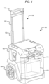
- FIG. 1 illustrates a portable power supply device or power supply 100.
- the power supply 100 includes, among other things, a housing 102.
- the housing 102 includes one or more wheels 104 and a handle assembly 106.
- the handle assembly 106 includes an inner tube 108 and an outer tube 110.
- the inner tube 108 fits inside the outer tube 110 and is slidable relative to the outer tube 110.
- the inner tube 108 is coupled to a horizontal holding member 112.
- the housing 102 of power supply 100 further includes an AC power input interface 114, a power output interface 116, and a display 118.
- the AC power input interface 114 includes multiple electrical connection interfaces configured to receive power from an external power source.
- the external power source is an AC power source.
- the AC power source may be a conventional wall outlet, such as a 120 V outlet or a 240 V outlet, found in North America.
- the AC power source may be a conventional wall outlet, such as a 220V outlet or 230V outlet, found outside of North America.
- the external power source is a DC power source.
- the DC power source may be one or more photovoltaic cells (e.g., a solar panel), an electric vehicle (EV) charging station, or any other DC power source.
- the AC power input interface 114 is replaced by or additionally includes a cable configured to plug into a conventional wall outlet.
- the AC power input interface 114 further includes one or more devices, such as antennas or induction coils, configured to wirelessly receive power from an external power source.
- the power received by the AC power input interface 114 may be used to charge an internal power source or battery core 120, disposed within the housing 102 of power supply 100.
- the power received by the AC power input interface 114 may also be used to provide passthrough power to one or more devices connected to the power output interface 116.
- the power output interface 116 includes one more power outlets.
- the power output interface 116 includes a plurality of AC power outlets 116A and DC power outlets 116B. It should be understood that number of power outlets included in the power output interface 116 is not limited to the power outlets illustrated in FIG. 1 .
- the power output interface 116 may include more or fewer power outlets than the power outlets included in the illustrated embodiment of power supply 100.
- the power output interface 116 is configured to provide power output by the battery core 120 to one or more peripheral devices.
- the power output interface 116 is configured to provide power provided by an external power source (e.g., from the power grid via the AC power input interface 114) directly to one or more peripheral devices.
- the one or more peripheral devices may be a smartphone, a tablet computer, a laptop computer, a portable music player, a power tool, a power tool battery pack, a power tool battery pack charger, or the like.
- the peripheral devices may be configured to receive DC and/or AC power from the power output interface 116.
- the display 118 is configured to indicate a state of the power supply 100 to a user, such as state of charge of the battery core 120 and/or fault conditions.
- the display 118 includes one or more light-emitting diode (“LED”) indicators configured to illuminate and display a current state of charge of battery core 120.
- the display 118 is, for example, a liquid crystal display (“LCD”), a light-emitting diode (“LED”) display, an organic LED (“OLED”) display, an electroluminescent display (“ELD”), a surface-conduction electron-emitter display (“SED”), a field emission display (“FED”), a thin-film transistor (“TFT”) LCD, etc.
- the power supply 100 does not include a display.
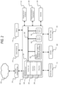
- FIG. 2 is a generalized schematic illustration of a controller 200 included in power supply 100.
- the controller 200 is electrically and/or communicatively connected to a variety of modules or components of the power supply 100.
- the controller 200 may be connected to the AC power input interface 114, the power output interface 116, the display 118, and the battery core 120.
- electrical and/or communicative connection between the controller 200 and the battery core 120 includes electrical and/or communicative connection between the controller 200 and components included in the battery core 120, such as, but not limited to, a plurality of battery cell assemblies and components included therein.
- the controller 200 is additionally electrically and/or communicatively connected to a plurality of power conversion components 204, a DC bus 208, a user interface 212, a network communications module 216, and a plurality of sensors 220.
- the power conversion components 204 will be described in greater detail below with reference to FIGS. 3-7 .
- the network communications module 216 is connected to a network 224 to enable the controller 200 to communicate with peripheral devices in the network 224, such as a smartphone or a server.
- the sensors 220 include, for example, one or more voltage sensors, one or more current sensors, one or more temperature sensors, and/or one or more additional sensors used for measuring electrical and/or other characteristics of the power supply 100. Each of the sensors 220 generates one or more output signals that are provided to the controller 200 for processing and evaluation.
- the user interface 212 is included to provide user control of the power supply 100.
- the user interface 212 can include any combination of digital and analog input devices required to achieve a desired level of control for the power supply 100.
- the user interface 212 may include a plurality of knobs, a plurality of dials, a plurality of switches, a plurality of buttons, or the like.
- the user interface 212 is integrated with the display 118 (e.g., as a touchscreen display 118).
- the controller 200 includes combinations of hardware and software that are operable to, among other things, control the operation of the power supply 100, communicate over the network 224, receive input from a user via the user interface 212, provide information to a user via the display 118, etc.
- the controller 200 includes, among other things, a processing unit 232 (e.g., a microprocessor, a microcontroller, an electronic processor, an electronic controller 200, or another suitable programmable device), a memory 236, input units 240, and output units 244.
- the processing unit 232 includes, among other things, a control unit 248, an arithmetic logic unit ("ALU") 252, and a plurality of registers 256, and is implemented using a known computer architecture (e.g., a modified Harvard architecture, a von Neumann architecture, etc.).
- the processing unit 232, the memory 236, the input units 240, and the output units 244, as well as the various modules or circuits connected to the controller 200 are connected by one or more control and/or data buses (e.g., common bus 260).
- the control and/or data buses are shown generally in FIG. 2 for illustrative purposes. Although the controller 200 is illustrated in FIG.
- controller 200 could also include multiple controllers configured to work together to achieve a desired level of control for the power supply 100.
- any control functions and processes described herein with respect to the controller 200 could also be performed by two or more controllers functioning in a distributed manner.
- the memory 236 is a non-transitory computer readable medium and includes, for example, a program storage area and a data storage area.
- the program storage area and the data storage area can include combinations of different types of memory 236, such as a read only memory (“ROM”), a random access memory (“RAM”) (e.g., dynamic RAM ["DRAM”], synchronous DRAM ["SDRAM”], etc.), electrically-erasable programmable ROM (“EEPROM”), flash memory, a hard disk, an SD card, or other suitable magnetic, optical, physical, or electronic memory devices.
- ROM read only memory
- RAM random access memory
- EEPROM electrically-erasable programmable ROM
- flash memory e.g., a hard disk, an SD card, or other suitable magnetic, optical, physical, or electronic memory devices.
- the processing unit 232 is connected to the memory 236 and is configured to execute software instructions that are capable of being stored in a RAM of the memory 236 (e.g., during execution), a ROM of the memory 236 (e.g., on a generally permanent basis), or another non-transitory computer readable medium such as another memory 236 or a disc.
- Software included in the implementation of the power supply 100 and controller 200 can be stored in the memory 236 of the controller 200.
- the software includes, for example, firmware, one or more applications, program data, filters, rules, one or more program modules, and other executable instructions.
- the controller 200 is configured to retrieve from the memory 236 and execute, among other things, instructions related to the control processes and methods described herein. In other embodiments, the controller 200 includes additional, fewer, or different components.
- the controller 200 is configured to monitor voltage, current, temperature, and/or other signals received from the various components described above.
- the controller 200 is configured to monitor voltage signals received from the battery core 120 when the battery core 120 is charged by an external power source connected to the AC power input interface 114.
- the controller 200 is configured to monitor voltage signals received from the battery core 120 when the battery core 120 provides power to one or more peripheral devices connected to the power output interface 116.
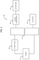
- FIG. 3 is a block diagram of a power system circuit 300 of the power supply 100 according to some embodiments.
- the power system circuit 300 includes the AC power input interface 114, an AC input filter 304, a voltage converter 308, the battery core 120, and the AC power outlets 116A.
- the AC input filter 304 is an electromagnetic interference ("EMI") filter 304 electrically connected between the AC power input interface 114 and the voltage converter 308.
- the EMI filter 304 provides filtering from the AC input to reduce conducted and radiated emissions in the power system circuit 300.
- the voltage converter 308 may be an active front end (“AFE”) drive circuit, and may alternatively be referred to herein as the AFE 308.
- the AFE 308 is configured to provide bidirectional power exchange to and from the battery core 120.
- the AFE 308 can be configured to operate as a rectifier in order to charge the battery core 120 with power supplied by the AC power input interface 114, and can be configured to operate as an inverter in order to discharge power from the battery core 120 to the AC power outlets 116A.
- the power system circuit 300 further includes at least one switch 312 (e.g., a transistor, a toggle switch, an electrical switch, a mechanical switch, a relay, etc.) configured to electrically connect components of the power system circuit 300.
- the power system circuit 300 provides for a reduced size, weight, and cost of the inverter system for the power supply 100 because charging and discharging of the battery core 120 can be achieved using the same switching devices and an inductor, as described below. By reducing the components in the power supply 100, less thermal management is also required.
- the power supply 100 is configured to operate as an uninterruptable power supply (UPS).
- UPS uninterruptable power supply
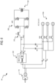
- FIG. 4 is a schematic diagram of a first topology of the power system circuit 300 of FIG. 3 .
- the at least one switch 312 includes a first switch K1.
- the at least one switch 312 is a relay.
- the first switch K1 is electrically connected between the output of the EMI filter 304 and the AFE 308 in order to selectively provide power from the AC power input interface 114 to the battery core 120.
- the battery core 120 may have a maximum voltage of at least 120V (e.g., 120V-500V). In some embodiments, the battery core 120 has a maximum voltage of at least 200V.
- the AFE 308 includes a plurality transistors (e.g., insulated-gate bipolar transistors) Q1, Q2, Q3, Q4 arranged in a bridge (e.g., an H-bridge) topology.
- An output filter 316 (e.g., a sine wave filter) is connected to the AFE 308 in order to provide low total harmonic distortion ("THD") of the AC power output from the AFE 308.
- the output filter 316 may be a sinusoidal filter, and includes at least one capacitor C1 (e.g., a sine wave filter capacitor) and at least one inductor L1.
- the battery core 120 has a maximum voltage of at least 400V DC.
- Each of the AC power outlets 116A may include a respective one of a plurality of circuit breakers CB1, CB2, CB3 to protect an external device from damage that may be caused by an overcurrent event.
- the power system circuit 300 includes three AC power outlets 116A.
- the number of AC outlets is not limited to three, and may be more than three or less than three.
- the first switch K1 is controlled by the controller 200 and enables the power supply 100 to operate in, for example, an AC bypass mode, an AC passthrough mode, a DC discharge mode, or an idle mode. In some embodiments, additional modes of operation are included.
- the first switch K1 When operating in the AC bypass mode, the first switch K1 is closed and the AFE 308 is disabled. As a result, AC power flows directly from the AC power input interface 114 to the AC power outlets 116A.
- the first switch K1 When operating in AC passthrough mode, the first switch K1 is closed and the AFE 308 is enabled to provide power to the battery core 120.
- the AC passthrough mode may alternatively be referred to herein as a charge mode for charging the battery core 120.
- AC power also still flows directly from the AC power input interface 114 to the AC power outlets 116A.
- the first switch K1 When operating in the DC discharge mode, the first switch K1 is open to disconnect the AC power input interface 114 from the power system circuit 300, and the AFE 308 is enabled to provide power from the battery core 120 to the AC power outlets 116A. When operating in idle mode, the first switch K1 is open and the AFE 308 is disabled. No power is provided to the AC power outlets 116A, and the battery core 120 is not being charged.
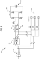
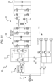
- FIGS. 5-10 are schematic diagrams of respective second, third, fourth, fifth, sixth, and seventh topologies of the power system circuit 300 that may be implemented in place of the first topology described above with reference to FIG. 4 . Operation of the power supply 100 according to each topology is substantially similar. Accordingly, similar components of the first topology, the second topology, the third topology, and the fourth topology are identified with common reference numerals. Differences among the first, second, third, fourth, fifth, sixth, and seventh topologies are described below.
- first switch K1 may be electrically connected between the AC power input interface 114 and the EMI filter 304 in order to selectively provide power from the AC power input interface 114 to the battery core 120. Similar to the first topology described above with reference to FIG. 4 , when operating in the AC bypass mode, the first switch K1 is closed and the AFE 308 is disabled. When operating in AC passthrough mode, the first switch K1 is closed and the AFE 308 is enabled to provide power to the battery core 120. AC power also still flows directly from the AC power input interface 114 to the AC power outlets 116A.
- the first switch K1 When operating in the DC discharge mode, the first switch K1 is open to disconnect the AC power input interface 114 from the power system circuit 300, and the AFE 308 is enabled to provide power from the battery core 120 to the AC power outlets 116A. When operating in idle mode, the first switch K1 is open and the AFE 308 is disabled.
- the power system circuit 300 can optionally include a second switch K2 connected between the EMI filter 304, the AFE 308, and the AC power outlets 116A to control power output to the AC power outlets 116A.
- the at least one switch 312 may include two first switches K1 and K2 electrically connected between the output of the EMI filter 304 and the AFE 308 in order to selectively provide power from the AC power input interface 114 to the battery core 120.
- the at least one switch 312 may further include second switches K3 and K4, third switches K5 and K6, and a fourth switch K7.
- the fourth switch K7 can selectively connect the output filter 316 to the power system circuit 300.
- Second switches K3 and K4 are electrically connected between the AC power input interface 114 and the AC power outlets 116A for selectively providing AC power directly from the AC power input interface 114 to the power output interface 116.
- Second switches K5 and K6 are electrically connected between the output filter 316 of the AFE 308 and the AC power outlets 116A in order to selectively provide power from the battery core 120 to the power output interface 116.
- the switches K1 and K2, K3 and K4, and K5 and K6 are alternatively provided as single switches rather than switch pairs in order to, for example, reduce the number of components included in the power system circuit 300.
- the power system circuit 300 may further include a DC-DC power converter 320 electrically connected between the AFE 308 and the battery core 120.
- the DC-DC power converter 320 is a non-isolated DC-DC power converter.
- the DC-DC power converter 320 may be implemented in a variety of manners.
- the DC-DC converter 320 may be implemented as a buck converter, a boost converter, a buck-boost converter, a switched capacitor converter, a single-ended primary-inductor converter (SEPIC), or the like.
- the DC-DC power converter 320 includes a capacitor C2 (e.g., an energy storage capacitor) connected in parallel with two series connected transistors Q5 and Q6.
- An inductor L2 is connected between the two transistors Q5 and Q6 to a positive power terminal of the battery core 120.
- the DC-DC converter 320 enables the power supply 100 to operate with a battery core 120 having a maximum voltage less than 400V.
- the battery core 120 may have a maximum voltage greater than, less than, or equal to 400V (DC).
- the DC-DC power converter 320 may also include a high-frequency (“HF”) isolation transformer 324.
- the HF isolation transformer 324 provides isolation between the AC power input interface 114, AC power outlets 116A, and the battery core 120.
- the isolated DC-DC converter 320 may again be implemented in various manners.
- the isolated DC-DC converter 320 may be implemented as a dual active bridge ("DAB") or a CLLC converter.
- the isolated DC-DC converter 320 includes the capacitor C2, the transistors Q5 and Q6, and the inductor L2, as described above with respect to FIG. 7 .
- the HF isolation transformer 324 is connected between the inductor L2 and the transistors Q5 and Q6.
- the battery core 120 may have a maximum voltage greater than, less than, or equal to 400V (DC).
- the power system circuit 300 may include a low-frequency (“LF") isolation transformer 328 electrically connected between the first switches K1 and K2, the second switches K5 and K6, and the output filter 316.
- the LF isolation transformer 328 provides isolation between the AC power input interface 114, AC power outlets 116A, and the battery core 120.
- the battery core 120 may have a maximum voltage greater than, less than, or equal to 400V (DC).
- the power system circuit 300 may include an inductor-capacitor-inductor (“LCL”) filter 332 for reducing harmonics in the power system circuit 300.
- the LCL filter includes inductors L3, L4, L5, and L6, capacitor C3, and damping resistors R1 and R2.
- the LCL filter is electrically connected between the first switches K1 and K2, the second switches K5 and K6, and the AFE 308.
- the AFE 308 includes switches Q1, Q2, Q3, and Q4. In the example illustrated in FIG.
- the DC-DC power converter 320 is implemented as a DAB converter 320 including capacitors C2, C4, and C5, an inductor L7, transistors Q5, Q6, Q7, and Q8 arranged in a first bridge, transistors S1, S2, S3, and S4 arranged in a second bridge, and the HF isolation transformer 324.
- the DC-DC power converter 320 may be implemented in another manner.
- the seventh topology illustrated in FIG. 10 is shown without the fourth switch K7, in some instances, the seventh topology of the power system circuit 300 includes the seventh switch K7.
- each of the at least one switch 312 is controlled by the controller 200 and enables the power supply 100 to operate in the AC bypass mode, the AC passthrough mode, the DC discharge mode, or the idle mode. In some embodiments, additional modes of operation are included.
- the first switches K1 and K2 are open, second switches K3 and K4 are closed, third switches K5 and K6 are open, and the fourth switch K7 is open.
- AC power flows directly from the AC power input interface 114 to the AC power outlets 116A.
- first switches K1 and K2 are closed, second switches K3 and K4 are closed, third switches K5 and K6 are open, and the fourth switch K7 is open.
- the AC passthrough mode enables power from the AC power input interface 114 to be simultaneously provided to both the AC power outlets 116A to power an external device, and to the AFE 308 to charge the battery core 120.
- first switches K1 and K2 are open, second switches K3 and K4 are open, third switches K5 and K6 are closed, and the fourth switch K7 is closed.
- the fourth switch K7 is not closed or is intermittently closed (e.g., based on a pulse-width modulated [PWM] signal).
- PWM pulse-width modulated
- the DC discharge mode enables the battery core 120 to supply power to the AC power outlets 116A via the AFE 308.
- each of the at least one switch 312 is opened. No power is provided to the AC power outlets 116A, and the battery core 120 is not being charged.
- FIG. 11 illustrates a control process 1000 implemented by the controller 200 for controlling the power system circuit 300 during passthrough operation (i.e., the AC passthrough mode).
- the control process 1000 includes sensing the AC load current requested at the AC power outlets 116A, and the current through the inductor L1.
- the controller 200 determines the corresponding root mean square ("RMS") load current, and the difference between the RMS load current and a maximum RMS input current.
- RMS root mean square
- the maximum AC input current may be 15 Amps.
- the controller 200 is configured to determine a maximum charging current that would be available to charge the battery core 120. The maximum charging current can be compared to a charge current requested by the battery core 120.
- the smaller of the maximum charging current and the charge current requested is selected and corresponds to a reference current for the inductor L1.
- the reference current for the inductor L1 is compared to a sensed current of the inductor L1 to produce a charge current error value.
- the charge current error value is provided to a PWM controller (e.g., within controller 200).
- the PWM controller is configured to control the current flowing through the inductor L1 by controlling a pulse width modulation (“PWM”) command signal to control the transistors in the AFE 308.
- PWM pulse width modulation
- the PWM command signal can be adjusted to regulate the charging current provided to the battery core 120.
- FIG. 12 illustrates a method 1100 implemented by the controller 200 for operating the portable power supply 100 in the AC bypass mode, the passthrough mode, the DC discharge mode, or the idle mode.
- the method 900 includes repeatedly determining if AC power is present at the AC power input interface 114 (STEP 1105). If AC power is present at STEP 1105, the controller 200 determines the state of charge ("SOC") of the battery core 120 (STEP 1110). If the controller 200 determines that the battery core 120 is less than fully charged, the controller 200 controls the power supply 100 for operation in AC passthrough mode (STEP 1115), and charges the battery core 120 while providing power to the AC power outlets 116A. In contrast, if the controller 200 determines that the battery core 120 is fully charged, the controller 200 controls the power supply 100 for operation in AC bypass mode (STEP 1120), and does not charge the battery core 120.
- SOC state of charge
- the controller 200 determines if AC power is requested at the AC power outlets 116A (STEP 1125). If AC power is requested at the AC power outlets 116A, the controller 200 controls the power supply 100 for operation in DC discharge mode (STEP 1130), and supplies power to the AC power outlets 116A via the battery core 120 and the AFE 308. In contrast, if the controller 200 determines that AC power is not present at the AC power input interface 114 and AC power is not requested at the AC power outlets 116A, the controller 200 controls the power supply 100 for operation in the idle mode.
Landscapes
- Engineering & Computer Science (AREA)
- Power Engineering (AREA)
- Business, Economics & Management (AREA)
- Emergency Management (AREA)
- Physics & Mathematics (AREA)
- Electromagnetism (AREA)
- Charge And Discharge Circuits For Batteries Or The Like (AREA)
Abstract
Description
- This application claims the benefit of
U.S. Provisional Patent Application No. 63/397,027, filed August 11, 2022 U.S. Provisional Patent Application No. 63/383,529, filed November 14, 2022 - Embodiments herein relate to portable power supplies.
- Portable power supplies described herein include an alternating current ("AC) power input interface, an AC power output interface, a direct current ("DC") power output interface, and a battery core configured to provide DC power to the DC power output interface. The power supply further includes at least one switch including a first switch, a second switch, and a third switch. The first switch is electrically connected between the AC power input interface and the battery core. The second switch is electrically connected between the AC power input interface and the AC power output interface. The third switch is electrically connected between the battery core and the AC power output interface. The power supply also includes a controller configured to control the at least one switch to selectively provide an AC power output to the AC power output interface based on power received from either the AC power input interface or the battery core.
- In some aspects, the portable power supplies described herein further include an electromagnetic interference ("EMI") filter electrically connected between the AC power input and the first switch and a voltage converter electrically connected between the first switch and the battery core.
- In some aspects, the portable power supplies described herein further include an output filter including an inductor and a capacitor, the output filter electrically connected between the voltage converter and the AC power output interface.
- In some aspects, the portable power supplies described herein further include an inductor-capacitor-inductor ("LCL") filter electrically connected between the first switch and the voltage converter.
- In some aspects, the at least one switch further includes a second switch and a third switch, the second switch is electrically connected between the AC power input interface and the AC power output interface, and the third switch is electrically connected between the battery core and the AC power output interface.
- In some aspects, the portable power supplies described herein further include an electromagnetic interference ("EMI") filter electrically connected between the AC power input and the first switch, and a voltage converter electrically connected between the first switch, the third switch, and the battery core.
- In some aspects, the portable power supplies described herein further include an output filter including an inductor, a capacitor, and a fourth switch, the output filter electrically connected between the voltage converter and the third switch.
- In some aspects, the battery core has a maximum voltage of at least 400V.
- In some aspects, the portable power supplies described herein further include a low frequency isolation transformer electrically connected between the output filter, the first switch, and the third switch.
- In some aspects, the portable power supplies described herein further include a DC-DC power converter electrically connected between the voltage converter and the battery core.
- In some aspects, the battery core has a maximum voltage of less than 400V.
- In some aspects, the DC-DC power converter includes a high-frequency isolation transformer.
- In some aspects, the controller is further configured to determine whether AC power is present at the AC power input interface, determine, in response to AC power being present at the AC power input interface, a state of charge of the battery core, and control, in response to the state of charge of the battery core being less than fully charged, the portable power supply in an AC passthrough mode, wherein, when in the AC passthrough mode, the first switch is closed, the second switch is closed, and the third switch is open.
- In some aspects, the controller is further configured to determine whether AC power is present at the AC power input interface, determine, in response to AC power being present at the AC power input interface, a state of charge of the battery core, control, in response to the state of charge of the battery core being fully charged, the portable power supply in an AC bypass mode, wherein, when in the AC bypass mode, the first switch is open, the second switch is closed, and the third switch is open.
- In some aspects, the controller is further configured to determine whether AC power is present at the AC power input interface, determine, in response to AC power not being present at the AC power input interface, whether AC power is requested at the AC power output interface, control, in response to determining that AC power is requested at the AC power output interface, the portable power supply in a DC discharge mode, wherein, when in the DC discharge mode, the first switch is open, the second switch is open, and the third switch is closed.
- In some aspects, the controller is further configured to determine whether AC power is present at the AC power input interface, determine, in response to AC power not being present at the AC power input interface, whether AC power is requested at the AC power output interface, control, in response to determining that AC power is not requested at the AC power output interface, the portable power supply in an idle mode, wherein, when in the idle mode, the first switch is open, the second switch is open, and the third switch is open.
- In some aspects, the controller is further configured to determine whether AC power is present at the AC power input interface, determine, in response to AC power being present at the AC power input interface, a state of charge of the battery core, and control, in response to the state of charge of the battery core being less than fully charged, the portable power supply in an AC passthrough mode, wherein, when in the AC passthrough mode, the first switch is closed, and a voltage converter electrically connected between the first switch and the battery core is enabled.
- In some aspects, the controller is further configured to determine whether AC power is present at the AC power input interface, determine, in response to AC power being present at the AC power input interface, a state of charge of the battery core, control, in response to the state of charge of the battery core being fully charged, the portable power supply in an AC bypass mode, wherein, when in the AC bypass mode, the first switch is closed, and a voltage converter electrically connected between the first switch and the battery core is disabled.
- In some aspects, the controller is further configured to determine whether AC power is present at the AC power input interface, determine, in response to AC power not being present at the AC power input interface, whether AC power is requested at the AC power output interface, control, in response to determining that AC power is requested at the AC power output interface, the portable power supply in a DC discharge mode, wherein, when in the DC discharge mode, the first switch is open, and a voltage converter electrically connected between the first switch and the battery core is enabled.
- In some aspects, the controller is further configured to determine whether AC power is present at the AC power input interface, determine, in response to AC power not being present at the AC power input interface, whether AC power is requested at the AC power output interface, control, in response to determining that AC power is not requested at the AC power output interface, the portable power supply in an idle mode, wherein, when in the idle mode, the first switch is open, and a voltage converter electrically connected between the first switch and the battery core is disabled.
- Methods described herein include receiving power from either an alternating current ("AC") power input interface of the portable power supply or a battery core of the power supply, and controlling at least one switch of the portable power supply to selectively provide an AC power output to an AC power output interface based on power received from either the AC power input interface of the portable power supply or the battery core of the portable power supply, the at least one switch including a first switch electrically connected between the AC power input interface and the battery core.
- In some aspects, the methods described herein further include determining whether AC power is present at the AC power input interface, determining, in response to AC power being present at the AC power input interface, a state of charge of the battery core, and controlling, in response to the state of charge of the battery core being less than fully charged, the at least one switch for operation of the portable power supply in an AC passthrough mode, wherein, when in the AC passthrough mode, AC power is provided from the AC power input interface to the AC power output interface and the battery core.
- In some aspects, when in the AC passthrough mode, the first switch is closed, a second switch electrically connected between the AC power input interface and the AC power output interface is closed, and a third switch electrically connected between the battery core and the AC power output interface is open.
- In some aspects, when in the AC passthrough mode, the first switch is closed, and a voltage converter electrically connected between the first switch and the battery core is enabled.
- In some aspects, the methods described herein further include determining whether AC power is present at the AC power input interface, determining, in response to AC power being present at the AC power input interface, a state of charge of the battery core, controlling, in response to the state of charge of the battery core being fully charged, the at least one switch for operation of the portable power supply in an AC bypass mode, wherein, when in the AC bypass mode, AC power is provided from the AC power input interface to the AC power output interface.
- In some aspects, when in the AC bypass mode, the first switch is open, a second switch electrically connected between the AC power input interface and the AC power output interface is closed, and a third switch electrically connected between the battery core and the AC power output interface is open.
- In some aspects, when in the AC bypass mode, the first switch is closed, and a voltage converter electrically connected between the first switch and the battery core is disabled.
- In some aspects, the methods described herein further include determining whether AC power is present at the AC power input interface, determining, in response to AC power not being present at the AC power input interface, whether AC power is requested at the AC power output interface, controlling, in response to determining that AC power is requested at the AC power output interface, at least one switch for operation of the portable power supply in a DC discharge mode, wherein, when in the DC discharge mode, power is provided from the battery core to the AC power output interface.
- In some aspects, when in the DC discharge mode, the first switch is open, a second switch electrically connected between the AC power input interface and the AC power output interface is open, and a third switch electrically connected between the battery core and the AC power output interface is closed.
- In some aspects, when in the DC discharge mode, the first switch is open, and a voltage converter electrically connected between the first switch and the battery core is enabled.
- In some aspects, the methods described herein further include determining whether AC power is present at the AC power input interface; determining, in response to AC power not being present at the AC power input interface, whether AC power is requested at the AC power output interface; controlling, in response to determining that AC power is not requested at the AC power output interface, at least one switch for operation of the portable power supply in an idle mode, wherein, when in the idle mode, power is provided to neither the AC power output interface nor the battery core.
- In some aspects, when in the idle mode, the first switch is open, a second switch electrically connected between the AC power input interface and the AC power output interface is open is open, and a third switch electrically connected between the battery core and the AC power output interface is open.
- In some aspects, when in the idle mode, the first switch is open, and a voltage converter electrically connected between the first switch and the battery core is disabled.
- Portable power supplies described herein include an internal power source configured to provide power to a device connected to the portable power supply, a power input interface configured to charge the internal power source, a power output interface, at least one switch including a first switch electrically connected between the power input interface and the internal power source, and a controller configured to determine whether power is present at the power input interface, and control at least one switch of the portable power supply to selectively provide power to a power output interface from either the power input interface or the internal power source based on the determination
- In some aspects, the controller is further configured to determine, in response to power being present at the power input interface, a state of charge of the internal power source, and control, in response to the state of charge of the internal power source being less than a threshold, the at least one switch for operation of the portable power supply in a passthrough mode, wherein, when in the passthrough mode, power is provided from the power input interface to the power output interface and the internal power source.
- In some aspects, the controller is further configured to determine, in response to power being present at the power input interface, a state of charge of the internal power source, and controlling, in response to the state of charge of the internal power source meeting or exceeding a threshold, the at least one switch for operation of the portable power supply in a bypass mode, wherein, when in the bypass mode, power is provided from the power input interface to the power output interface.
- In some aspects, the controller is further configured to determine, in response to power not being present at the power input interface, whether power is requested at the power output interface, control, in response to determining that power is requested at the power output interface, the at least one switch for operation of the portable power supply in a discharge mode, wherein, when in the discharge mode, power is provided from the internal power source to the power output interface.
- In some aspects, the controller is further configured to determine, in response to power not being present at the power input interface, whether power is requested at the power output interface, control, in response to determining that power is not requested at the power output interface, the at least one switch for operation of the portable power supply in an idle mode, wherein, when in the idle mode, power is provided to neither the power output interface the battery core.
- Before any embodiments are explained in detail, it is to be understood that the embodiments are not limited in application to the details of the configurations and arrangements of components set forth in the following description or illustrated in the accompanying drawings. The embodiments are capable of being practiced or of being carried out in various ways. Also, it is to be understood that the phraseology and terminology used herein are for the purpose of description and should not be regarded as limiting. The use of "including," "comprising," or "having" and variations thereof are meant to encompass the items listed thereafter and equivalents thereof as well as additional items. Unless specified or limited otherwise, the terms "mounted," "connected," "supported," and "coupled" and variations thereof are used broadly and encompass both direct and indirect mountings, connections, supports, and couplings.
- Unless the context of their usage unambiguously indicates otherwise, the articles "a," "an," and "the" should not be interpreted as meaning "one" or "only one." Rather these articles should be interpreted as meaning "at least one" or "one or more." Likewise, when the terms "the" or "said" are used to refer to a noun previously introduced by the indefinite article "a" or "an," "the" and "said" mean "at least one" or "one or more" unless the usage unambiguously indicates otherwise.
- In addition, it should be understood that embodiments may include hardware, software, and electronic components or modules that, for purposes of discussion, may be illustrated and described as if the majority of the components were implemented solely in hardware. However, one of ordinary skill in the art, and based on a reading of this detailed description, would recognize that, in at least one embodiment, the electronic-based aspects may be implemented in software (e.g., stored on non-transitory computer-readable medium) executable by one or more processing units, such as a microprocessor and/or application specific integrated circuits ("ASICs"). As such, it should be noted that a plurality of hardware and software based devices, as well as a plurality of different structural components, may be utilized to implement the embodiments. For example, "servers," "computing devices," "controllers," "processors," etc., described in the specification can include one or more processing units, one or more computer-readable medium modules, one or more input/output interfaces, and various connections (e.g., a system bus) connecting the components.
- Relative terminology, such as, for example, "about," "approximately," "substantially," etc., used in connection with a quantity or condition would be understood by those of ordinary skill to be inclusive of the stated value and has the meaning dictated by the context (e.g., the term includes at least the degree of error associated with the measurement accuracy, tolerances [e.g., manufacturing, assembly, use, etc.] associated with the particular value, etc.). Such terminology should also be considered as disclosing the range defined by the absolute values of the two endpoints. For example, the expression "from about 2 to about 4" also discloses the range "from 2 to 4". The relative terminology may refer to plus or minus a percentage (e.g., 1%, 5%, 10%) of an indicated value.
- It should be understood that although certain drawings illustrate hardware and software located within particular devices, these depictions are for illustrative purposes only. Functionality described herein as being performed by one component may be performed by multiple components in a distributed manner. Likewise, functionality performed by multiple components may be consolidated and performed by a single component. In some embodiments, the illustrated components may be combined or divided into separate software, firmware and/or hardware. For example, instead of being located within and performed by a single electronic processor, logic and processing may be distributed among multiple electronic processors. Regardless of how they are combined or divided, hardware and software components may be located on the same computing device or may be distributed among different computing devices connected by one or more networks or other suitable communication links. Similarly, a component described as performing particular functionality may also perform additional functionality not described herein. For example, a device or structure that is "configured" in a certain way is configured in at least that way but may also be configured in ways that are not explicitly listed.
- Accordingly, in the claims, if an apparatus, method, or system is claimed, for example, as including a controller, control unit, electronic processor, computing device, logic element, module, memory module, communication channel or network, or other element configured in a certain manner, for example, to perform multiple functions, the claim or claim element should be interpreted as meaning one or more of such elements where any one of the one or more elements is configured as claimed, for example, to make any one or more of the recited multiple functions, such that the one or more elements, as a set, perform the multiple functions collectively.
- Other aspects of the embodiments will become apparent by consideration of the detailed description and accompanying drawings.
-
-
FIG. 1 illustrates a perspective view of a portable power supply device, according to some embodiments. -
FIG. 2 illustrates a control system for the portable power supply device ofFIG. 1 , according to some embodiments. -
FIG. 3 illustrates a schematic diagram of a power system of the portable power supply device ofFIG. 1 , according to some embodiments. -
FIG. 4 illustrates a schematic diagram of a power system of the portable power supply device ofFIG. 1 , according to some embodiments. -
FIG. 5 illustrates a schematic diagram of a power system of the portable power supply device ofFIG. 1 , according to some embodiments. -
FIG. 6 illustrates a schematic diagram of a power system of the portable power supply device ofFIG. 1 , according to some embodiments. -
FIG. 7 illustrates a schematic diagram of a power system of the power supply device ofFIG. 1 , according to some embodiments. -
FIG. 8 illustrates a schematic diagram of a power system of the power supply device ofFIG. 1 , according to some embodiments. -
FIG. 9 illustrates a schematic diagram of a power system of the power supply device ofFIG. 1 , according to some embodiments. -
FIG. 10 illustrates a schematic diagram of a power system of the power supply device ofFIG. 1 , according to some embodiments. -
FIG. 11 illustrates a control process for controlling the portable power supply device ofFIG. 1 , according to some embodiments. -
FIG. 12 illustrates a method for operating the portable power supply device ofFIG. 1 , according to some embodiments. -
FIG. 1 illustrates a portable power supply device orpower supply 100. Thepower supply 100 includes, among other things, ahousing 102. In some embodiments, thehousing 102 includes one ormore wheels 104 and ahandle assembly 106. Thehandle assembly 106 includes aninner tube 108 and anouter tube 110. Theinner tube 108 fits inside theouter tube 110 and is slidable relative to theouter tube 110. Theinner tube 108 is coupled to ahorizontal holding member 112. Thehousing 102 ofpower supply 100 further includes an ACpower input interface 114, apower output interface 116, and adisplay 118. In the illustrated embodiment, the ACpower input interface 114 includes multiple electrical connection interfaces configured to receive power from an external power source. In some embodiments, the external power source is an AC power source. For example, the AC power source may be a conventional wall outlet, such as a 120 V outlet or a 240 V outlet, found in North America. As another example, the AC power source may be a conventional wall outlet, such as a 220V outlet or 230V outlet, found outside of North America. In some embodiments, the external power source is a DC power source. For example, the DC power source may be one or more photovoltaic cells (e.g., a solar panel), an electric vehicle (EV) charging station, or any other DC power source. In some embodiments, the ACpower input interface 114 is replaced by or additionally includes a cable configured to plug into a conventional wall outlet. In some embodiments, the ACpower input interface 114 further includes one or more devices, such as antennas or induction coils, configured to wirelessly receive power from an external power source. The power received by the ACpower input interface 114 may be used to charge an internal power source orbattery core 120, disposed within thehousing 102 ofpower supply 100. - The power received by the AC
power input interface 114 may also be used to provide passthrough power to one or more devices connected to thepower output interface 116. Thepower output interface 116 includes one more power outlets. In the illustrated embodiment, thepower output interface 116 includes a plurality ofAC power outlets 116A andDC power outlets 116B. It should be understood that number of power outlets included in thepower output interface 116 is not limited to the power outlets illustrated inFIG. 1 . For example, in some embodiments of thepower supply 100, thepower output interface 116 may include more or fewer power outlets than the power outlets included in the illustrated embodiment ofpower supply 100. - In some embodiments, the
power output interface 116 is configured to provide power output by thebattery core 120 to one or more peripheral devices. In some embodiments, thepower output interface 116 is configured to provide power provided by an external power source (e.g., from the power grid via the AC power input interface 114) directly to one or more peripheral devices. The one or more peripheral devices may be a smartphone, a tablet computer, a laptop computer, a portable music player, a power tool, a power tool battery pack, a power tool battery pack charger, or the like. The peripheral devices may be configured to receive DC and/or AC power from thepower output interface 116. - The
display 118 is configured to indicate a state of thepower supply 100 to a user, such as state of charge of thebattery core 120 and/or fault conditions. In some embodiments thedisplay 118 includes one or more light-emitting diode ("LED") indicators configured to illuminate and display a current state of charge ofbattery core 120. In some embodiments, thedisplay 118 is, for example, a liquid crystal display ("LCD"), a light-emitting diode ("LED") display, an organic LED ("OLED") display, an electroluminescent display ("ELD"), a surface-conduction electron-emitter display ("SED"), a field emission display ("FED"), a thin-film transistor ("TFT") LCD, etc. In other embodiments, thepower supply 100 does not include a display. -
FIG. 2 is a generalized schematic illustration of acontroller 200 included inpower supply 100. Thecontroller 200 is electrically and/or communicatively connected to a variety of modules or components of thepower supply 100. For example, thecontroller 200 may be connected to the ACpower input interface 114, thepower output interface 116, thedisplay 118, and thebattery core 120. Persons skilled in the art will recognize that electrical and/or communicative connection between thecontroller 200 and thebattery core 120 includes electrical and/or communicative connection between thecontroller 200 and components included in thebattery core 120, such as, but not limited to, a plurality of battery cell assemblies and components included therein. - The
controller 200 is additionally electrically and/or communicatively connected to a plurality ofpower conversion components 204, aDC bus 208, auser interface 212, anetwork communications module 216, and a plurality ofsensors 220. Thepower conversion components 204 will be described in greater detail below with reference toFIGS. 3-7 . - The
network communications module 216 is connected to anetwork 224 to enable thecontroller 200 to communicate with peripheral devices in thenetwork 224, such as a smartphone or a server. Thesensors 220 include, for example, one or more voltage sensors, one or more current sensors, one or more temperature sensors, and/or one or more additional sensors used for measuring electrical and/or other characteristics of thepower supply 100. Each of thesensors 220 generates one or more output signals that are provided to thecontroller 200 for processing and evaluation. Theuser interface 212 is included to provide user control of thepower supply 100. Theuser interface 212 can include any combination of digital and analog input devices required to achieve a desired level of control for thepower supply 100. For example, theuser interface 212 may include a plurality of knobs, a plurality of dials, a plurality of switches, a plurality of buttons, or the like. In some embodiments, theuser interface 212 is integrated with the display 118 (e.g., as a touchscreen display 118). - The
controller 200 includes combinations of hardware and software that are operable to, among other things, control the operation of thepower supply 100, communicate over thenetwork 224, receive input from a user via theuser interface 212, provide information to a user via thedisplay 118, etc. For example, thecontroller 200 includes, among other things, a processing unit 232 (e.g., a microprocessor, a microcontroller, an electronic processor, anelectronic controller 200, or another suitable programmable device), amemory 236,input units 240, andoutput units 244. Theprocessing unit 232 includes, among other things, acontrol unit 248, an arithmetic logic unit ("ALU") 252, and a plurality ofregisters 256, and is implemented using a known computer architecture (e.g., a modified Harvard architecture, a von Neumann architecture, etc.). Theprocessing unit 232, thememory 236, theinput units 240, and theoutput units 244, as well as the various modules or circuits connected to thecontroller 200 are connected by one or more control and/or data buses (e.g., common bus 260). The control and/or data buses are shown generally inFIG. 2 for illustrative purposes. Although thecontroller 200 is illustrated inFIG. 2 as onecontroller 200, thecontroller 200 could also include multiple controllers configured to work together to achieve a desired level of control for thepower supply 100. As such, any control functions and processes described herein with respect to thecontroller 200 could also be performed by two or more controllers functioning in a distributed manner. - The
memory 236 is a non-transitory computer readable medium and includes, for example, a program storage area and a data storage area. The program storage area and the data storage area can include combinations of different types ofmemory 236, such as a read only memory ("ROM"), a random access memory ("RAM") (e.g., dynamic RAM ["DRAM"], synchronous DRAM ["SDRAM"], etc.), electrically-erasable programmable ROM ("EEPROM"), flash memory, a hard disk, an SD card, or other suitable magnetic, optical, physical, or electronic memory devices. Theprocessing unit 232 is connected to thememory 236 and is configured to execute software instructions that are capable of being stored in a RAM of the memory 236 (e.g., during execution), a ROM of the memory 236 (e.g., on a generally permanent basis), or another non-transitory computer readable medium such as anothermemory 236 or a disc. Software included in the implementation of thepower supply 100 andcontroller 200 can be stored in thememory 236 of thecontroller 200. The software includes, for example, firmware, one or more applications, program data, filters, rules, one or more program modules, and other executable instructions. Thecontroller 200 is configured to retrieve from thememory 236 and execute, among other things, instructions related to the control processes and methods described herein. In other embodiments, thecontroller 200 includes additional, fewer, or different components. - During operation of the
power supply 100, thecontroller 200 is configured to monitor voltage, current, temperature, and/or other signals received from the various components described above. For example, thecontroller 200 is configured to monitor voltage signals received from thebattery core 120 when thebattery core 120 is charged by an external power source connected to the ACpower input interface 114. As another example, thecontroller 200 is configured to monitor voltage signals received from thebattery core 120 when thebattery core 120 provides power to one or more peripheral devices connected to thepower output interface 116. -
FIG. 3 is a block diagram of apower system circuit 300 of thepower supply 100 according to some embodiments. Thepower system circuit 300 includes the ACpower input interface 114, anAC input filter 304, avoltage converter 308, thebattery core 120, and theAC power outlets 116A. In some embodiments, theAC input filter 304 is an electromagnetic interference ("EMI")filter 304 electrically connected between the ACpower input interface 114 and thevoltage converter 308. TheEMI filter 304 provides filtering from the AC input to reduce conducted and radiated emissions in thepower system circuit 300. Thevoltage converter 308 may be an active front end ("AFE") drive circuit, and may alternatively be referred to herein as theAFE 308. TheAFE 308 is configured to provide bidirectional power exchange to and from thebattery core 120. For example, theAFE 308 can be configured to operate as a rectifier in order to charge thebattery core 120 with power supplied by the ACpower input interface 114, and can be configured to operate as an inverter in order to discharge power from thebattery core 120 to theAC power outlets 116A. Thepower system circuit 300 further includes at least one switch 312 (e.g., a transistor, a toggle switch, an electrical switch, a mechanical switch, a relay, etc.) configured to electrically connect components of thepower system circuit 300. In some embodiments, thepower system circuit 300 provides for a reduced size, weight, and cost of the inverter system for thepower supply 100 because charging and discharging of thebattery core 120 can be achieved using the same switching devices and an inductor, as described below. By reducing the components in thepower supply 100, less thermal management is also required. In some embodiments, thepower supply 100 is configured to operate as an uninterruptable power supply (UPS). -
FIG. 4 is a schematic diagram of a first topology of thepower system circuit 300 ofFIG. 3 . The at least one switch 312 includes a first switch K1. In some embodiments, the at least one switch 312 is a relay. The first switch K1 is electrically connected between the output of theEMI filter 304 and theAFE 308 in order to selectively provide power from the ACpower input interface 114 to thebattery core 120. Thebattery core 120 may have a maximum voltage of at least 120V (e.g., 120V-500V). In some embodiments, thebattery core 120 has a maximum voltage of at least 200V. TheAFE 308 includes a plurality transistors (e.g., insulated-gate bipolar transistors) Q1, Q2, Q3, Q4 arranged in a bridge (e.g., an H-bridge) topology. An output filter 316 (e.g., a sine wave filter) is connected to theAFE 308 in order to provide low total harmonic distortion ("THD") of the AC power output from theAFE 308. Theoutput filter 316 may be a sinusoidal filter, and includes at least one capacitor C1 (e.g., a sine wave filter capacitor) and at least one inductor L1. In some embodiments, thebattery core 120 has a maximum voltage of at least 400V DC. Each of theAC power outlets 116A may include a respective one of a plurality of circuit breakers CB1, CB2, CB3 to protect an external device from damage that may be caused by an overcurrent event. In the illustrated embodiment, thepower system circuit 300 includes threeAC power outlets 116A. However, the number of AC outlets is not limited to three, and may be more than three or less than three. - The first switch K1 is controlled by the
controller 200 and enables thepower supply 100 to operate in, for example, an AC bypass mode, an AC passthrough mode, a DC discharge mode, or an idle mode. In some embodiments, additional modes of operation are included. - When operating in the AC bypass mode, the first switch K1 is closed and the
AFE 308 is disabled. As a result, AC power flows directly from the ACpower input interface 114 to theAC power outlets 116A. - When operating in AC passthrough mode, the first switch K1 is closed and the
AFE 308 is enabled to provide power to thebattery core 120. The AC passthrough mode may alternatively be referred to herein as a charge mode for charging thebattery core 120. AC power also still flows directly from the ACpower input interface 114 to theAC power outlets 116A. - When operating in the DC discharge mode, the first switch K1 is open to disconnect the AC
power input interface 114 from thepower system circuit 300, and theAFE 308 is enabled to provide power from thebattery core 120 to theAC power outlets 116A. When operating in idle mode, the first switch K1 is open and theAFE 308 is disabled. No power is provided to theAC power outlets 116A, and thebattery core 120 is not being charged. -
FIGS. 5-10 are schematic diagrams of respective second, third, fourth, fifth, sixth, and seventh topologies of thepower system circuit 300 that may be implemented in place of the first topology described above with reference toFIG. 4 . Operation of thepower supply 100 according to each topology is substantially similar. Accordingly, similar components of the first topology, the second topology, the third topology, and the fourth topology are identified with common reference numerals. Differences among the first, second, third, fourth, fifth, sixth, and seventh topologies are described below. - Referring now to
FIG. 5 , first switch K1 may be electrically connected between the ACpower input interface 114 and theEMI filter 304 in order to selectively provide power from the ACpower input interface 114 to thebattery core 120. Similar to the first topology described above with reference toFIG. 4 , when operating in the AC bypass mode, the first switch K1 is closed and theAFE 308 is disabled. When operating in AC passthrough mode, the first switch K1 is closed and theAFE 308 is enabled to provide power to thebattery core 120. AC power also still flows directly from the ACpower input interface 114 to theAC power outlets 116A. When operating in the DC discharge mode, the first switch K1 is open to disconnect the ACpower input interface 114 from thepower system circuit 300, and theAFE 308 is enabled to provide power from thebattery core 120 to theAC power outlets 116A. When operating in idle mode, the first switch K1 is open and theAFE 308 is disabled. In some embodiments, thepower system circuit 300 can optionally include a second switch K2 connected between theEMI filter 304, theAFE 308, and theAC power outlets 116A to control power output to theAC power outlets 116A. - Referring now to
FIG. 6 , the at least one switch 312 may include two first switches K1 and K2 electrically connected between the output of theEMI filter 304 and theAFE 308 in order to selectively provide power from the ACpower input interface 114 to thebattery core 120. The at least one switch 312 may further include second switches K3 and K4, third switches K5 and K6, and a fourth switch K7. The fourth switch K7 can selectively connect theoutput filter 316 to thepower system circuit 300. Second switches K3 and K4 are electrically connected between the ACpower input interface 114 and theAC power outlets 116A for selectively providing AC power directly from the ACpower input interface 114 to thepower output interface 116. Second switches K5 and K6 are electrically connected between theoutput filter 316 of theAFE 308 and theAC power outlets 116A in order to selectively provide power from thebattery core 120 to thepower output interface 116. In some embodiments, the switches K1 and K2, K3 and K4, and K5 and K6 are alternatively provided as single switches rather than switch pairs in order to, for example, reduce the number of components included in thepower system circuit 300. - Referring now to
FIG. 7 , thepower system circuit 300 may further include a DC-DC power converter 320 electrically connected between theAFE 308 and thebattery core 120. In the embodiment illustrated inFIG. 7 , the DC-DC power converter 320 is a non-isolated DC-DC power converter. The DC-DC power converter 320 may be implemented in a variety of manners. For example, the DC-DC converter 320 may be implemented as a buck converter, a boost converter, a buck-boost converter, a switched capacitor converter, a single-ended primary-inductor converter (SEPIC), or the like. In the illustrated embodiment, the DC-DC power converter 320 includes a capacitor C2 (e.g., an energy storage capacitor) connected in parallel with two series connected transistors Q5 and Q6. An inductor L2 is connected between the two transistors Q5 and Q6 to a positive power terminal of thebattery core 120. The DC-DC converter 320 enables thepower supply 100 to operate with abattery core 120 having a maximum voltage less than 400V. In some embodiments, thebattery core 120 may have a maximum voltage greater than, less than, or equal to 400V (DC). - Referring now to
FIG. 8 , the DC-DC power converter 320 may also include a high-frequency ("HF")isolation transformer 324. TheHF isolation transformer 324 provides isolation between the ACpower input interface 114,AC power outlets 116A, and thebattery core 120. The isolated DC-DC converter 320 may again be implemented in various manners. For example, the isolated DC-DC converter 320 may be implemented as a dual active bridge ("DAB") or a CLLC converter. In the illustrated embodiment, the isolated DC-DC converter 320 includes the capacitor C2, the transistors Q5 and Q6, and the inductor L2, as described above with respect toFIG. 7 . TheHF isolation transformer 324 is connected between the inductor L2 and the transistors Q5 and Q6. In the illustrated embodiment, thebattery core 120 may have a maximum voltage greater than, less than, or equal to 400V (DC). - Referring now to
FIG. 9 , thepower system circuit 300 may include a low-frequency ("LF")isolation transformer 328 electrically connected between the first switches K1 and K2, the second switches K5 and K6, and theoutput filter 316. TheLF isolation transformer 328 provides isolation between the ACpower input interface 114,AC power outlets 116A, and thebattery core 120. In the illustrated embodiment, thebattery core 120 may have a maximum voltage greater than, less than, or equal to 400V (DC). - Referring now to
FIG. 10 , thepower system circuit 300 may include an inductor-capacitor-inductor ("LCL")filter 332 for reducing harmonics in thepower system circuit 300. The LCL filter includes inductors L3, L4, L5, and L6, capacitor C3, and damping resistors R1 and R2. The LCL filter is electrically connected between the first switches K1 and K2, the second switches K5 and K6, and theAFE 308. TheAFE 308 includes switches Q1, Q2, Q3, and Q4. In the example illustrated inFIG. 10 , the DC-DC power converter 320 is implemented as aDAB converter 320 including capacitors C2, C4, and C5, an inductor L7, transistors Q5, Q6, Q7, and Q8 arranged in a first bridge, transistors S1, S2, S3, and S4 arranged in a second bridge, and theHF isolation transformer 324. However, as described above, the DC-DC power converter 320 may be implemented in another manner. Additionally, although the seventh topology illustrated inFIG. 10 is shown without the fourth switch K7, in some instances, the seventh topology of thepower system circuit 300 includes the seventh switch K7. - With respect to the third, fourth, fifth, sixth, and seventh topologies for the
power system circuit 300 described above, each of the at least one switch 312 is controlled by thecontroller 200 and enables thepower supply 100 to operate in the AC bypass mode, the AC passthrough mode, the DC discharge mode, or the idle mode. In some embodiments, additional modes of operation are included. - When operating in the AC bypass mode, the first switches K1 and K2 are open, second switches K3 and K4 are closed, third switches K5 and K6 are open, and the fourth switch K7 is open. As a result, AC power flows directly from the AC
power input interface 114 to theAC power outlets 116A. - When operating in the AC passthrough mode, first switches K1 and K2 are closed, second switches K3 and K4 are closed, third switches K5 and K6 are open, and the fourth switch K7 is open. The AC passthrough mode enables power from the AC
power input interface 114 to be simultaneously provided to both theAC power outlets 116A to power an external device, and to theAFE 308 to charge thebattery core 120. - When operating in the DC discharge mode, first switches K1 and K2 are open, second switches K3 and K4 are open, third switches K5 and K6 are closed, and the fourth switch K7 is closed. In some embodiments, the fourth switch K7 is not closed or is intermittently closed (e.g., based on a pulse-width modulated [PWM] signal). The DC discharge mode enables the
battery core 120 to supply power to theAC power outlets 116A via theAFE 308. When operating in idle mode, each of the at least one switch 312 is opened. No power is provided to theAC power outlets 116A, and thebattery core 120 is not being charged. -
FIG. 11 illustrates acontrol process 1000 implemented by thecontroller 200 for controlling thepower system circuit 300 during passthrough operation (i.e., the AC passthrough mode). Thecontrol process 1000 includes sensing the AC load current requested at theAC power outlets 116A, and the current through the inductor L1. Thecontroller 200 determines the corresponding root mean square ("RMS") load current, and the difference between the RMS load current and a maximum RMS input current. For example, the maximum AC input current may be 15 Amps. Based on the difference between the maximum AC input current and the RMS load current, thecontroller 200 is configured to determine a maximum charging current that would be available to charge thebattery core 120. The maximum charging current can be compared to a charge current requested by thebattery core 120. The smaller of the maximum charging current and the charge current requested is selected and corresponds to a reference current for the inductor L1. The reference current for the inductor L1 is compared to a sensed current of the inductor L1 to produce a charge current error value. The charge current error value is provided to a PWM controller (e.g., within controller 200). The PWM controller is configured to control the current flowing through the inductor L1 by controlling a pulse width modulation ("PWM") command signal to control the transistors in theAFE 308. The PWM command signal can be adjusted to regulate the charging current provided to thebattery core 120. -
FIG. 12 illustrates amethod 1100 implemented by thecontroller 200 for operating theportable power supply 100 in the AC bypass mode, the passthrough mode, the DC discharge mode, or the idle mode. The method 900 includes repeatedly determining if AC power is present at the AC power input interface 114 (STEP 1105). If AC power is present atSTEP 1105, thecontroller 200 determines the state of charge ("SOC") of the battery core 120 (STEP 1110). If thecontroller 200 determines that thebattery core 120 is less than fully charged, thecontroller 200 controls thepower supply 100 for operation in AC passthrough mode (STEP 1115), and charges thebattery core 120 while providing power to theAC power outlets 116A. In contrast, if thecontroller 200 determines that thebattery core 120 is fully charged, thecontroller 200 controls thepower supply 100 for operation in AC bypass mode (STEP 1120), and does not charge thebattery core 120. - If, at
STEP 1105, thecontroller 200 determines that AC power is not present at the ACpower input interface 114, thecontroller 200 determines if AC power is requested at theAC power outlets 116A (STEP 1125). If AC power is requested at theAC power outlets 116A, thecontroller 200 controls thepower supply 100 for operation in DC discharge mode (STEP 1130), and supplies power to theAC power outlets 116A via thebattery core 120 and theAFE 308. In contrast, if thecontroller 200 determines that AC power is not present at the ACpower input interface 114 and AC power is not requested at theAC power outlets 116A, thecontroller 200 controls thepower supply 100 for operation in the idle mode. - Although aspects of the present disclosure have been described in detail with reference to certain embodiments, variations and modifications exist within the scope and spirit of one or more independent aspects as described. Various features of the disclosure are set forth in the following claims.
- Representative features are set out in the following clauses, which stand alone or may be combined, in any combination, with one or more features disclosed in the text and/or drawings of the specification.
- 1. A portable power supply comprising:
- an alternating current ("AC") power input interface;
- an AC power output interface;
- a battery core;
- at least one switch including a first switch electrically connected between the AC power input interface and the battery core; and
- a controller configured to control the at least one switch to selectively provide an AC power output to the AC power output interface based on power received from either the AC power input interface or the battery core.
- 2. The portable power supply of
clause 1, further comprising:- an electromagnetic interference ("EMI") filter electrically connected between the AC power input and the first switch; and
- a voltage converter electrically connected between the first switch and the battery core.
- 3. The portable power supply of clause 2, further comprising:
an output filter including an inductor and a capacitor, the output filter electrically connected between the voltage converter and the AC power output interface. - 4. The portable power supply of any of clauses 2 and 3 further comprising:
an inductor-capacitor-inductor ("LCL") filter electrically connected between the first switch and the voltage converter. - 5. The portable power supply of any of clauses 1-4, wherein
the at least one switch further includes a second switch and a third switch,
the second switch is electrically connected between the AC power input interface and the AC power output interface, and the third switch is electrically connected between the battery core and the AC power output interface. - 6. The portable power supply of clause 5, further comprising:
- an electromagnetic interference ("EMI") filter electrically connected between the AC power input and the first switch; and
- a voltage converter electrically connected between the first switch, the third switch, and the battery core.
- 7. The portable power supply of clause 6, further comprising:
an output filter including an inductor, a capacitor, and a fourth switch, the output filter electrically connected between the voltage converter and the third switch. - 8. The portable power supply of clause 7, wherein the battery core has a maximum voltage of at least 400V.
- 9. The portable power supply of any of clauses 7 and 8, further comprising:
a low frequency isolation transformer electrically connected between the output filter, the first switch, and the third switch. - 10. The portable power supply of clause 6, further comprising:
a DC-DC power converter electrically connected between the voltage converter and the battery core. - 11. The portable power supply of clause 10, wherein the battery core has a maximum voltage of less than 400V.
- 12. The portable power supply of any of clauses 10 and 11, wherein the DC-DC power converter includes a high-frequency isolation transformer.
- 13. The portable power supply of any of clauses 5-12, wherein the controller is further configured to:
- determine whether AC power is present at the AC power input interface;
- determine, in response to AC power being present at the AC power input interface, a state of charge of the battery core; and
- control, in response to the state of charge of the battery core being less than fully charged, the portable power supply in an AC passthrough mode,
- wherein, when in the AC passthrough mode, the first switch is closed, the second switch is closed, and the third switch is open.
- 14. The portable power supply of any of clauses 5-12, wherein the controller is further configured to:
- determine whether AC power is present at the AC power input interface;
- determine, in response to AC power being present at the AC power input interface, a state of charge of the battery core;
- control, in response to the state of charge of the battery core being fully charged, the portable power supply in an AC bypass mode,
- wherein, when in the AC bypass mode, the first switch is open, the second switch is closed, and the third switch is open.
- 15. The portable power supply of any of clauses 5-12, wherein the controller is further configured to:
- determine whether AC power is present at the AC power input interface;
- determine, in response to AC power not being present at the AC power input interface, whether AC power is requested at the AC power output interface;
- control, in response to determining that AC power is requested at the AC power output interface, the portable power supply in a DC discharge mode,
- wherein, when in the DC discharge mode, the first switch is open, the second switch is open, and the third switch is closed.
- 16. The portable power supply of any of clauses 5-12, wherein the controller is further configured to:
- determine whether AC power is present at the AC power input interface;
- determine, in response to AC power not being present at the AC power input interface, whether AC power is requested at the AC power output interface;
- control, in response to determining that AC power is not requested at the AC power output interface, the portable power supply in an idle mode,
- wherein, when in the idle mode, the first switch is open, the second switch is open, and the third switch is open.
- 17. The portable power supply of any of clauses 1-4, wherein the controller is further configured to:
- determine whether AC power is present at the AC power input interface;
- determine, in response to AC power being present at the AC power input interface, a state of charge of the battery core; and
- control, in response to the state of charge of the battery core being less than fully charged, the portable power supply in an AC passthrough mode,
- wherein, when in the AC passthrough mode, the first switch is closed, and a voltage converter electrically connected between the first switch and the battery core is enabled.
- 18. The portable power supply of any of clauses 1-4, wherein the controller is further configured to:
- determine whether AC power is present at the AC power input interface;
- determine, in response to AC power being present at the AC power input interface, a state of charge of the battery core;
- control, in response to the state of charge of the battery core being fully charged, the portable power supply in an AC bypass mode,
- wherein, when in the AC bypass mode, the first switch is closed, and a voltage converter electrically connected between the first switch and the battery core is disabled.
- 19. The portable power supply of any of clauses 1-4, wherein the controller is further configured to:
- determine whether AC power is present at the AC power input interface;
- determine, in response to AC power not being present at the AC power input interface, whether AC power is requested at the AC power output interface;
- control, in response to determining that AC power is requested at the AC power output interface, the portable power supply in a DC discharge mode,
- wherein, when in the DC discharge mode, the first switch is open, and a voltage converter electrically connected between the first switch and the battery core is enabled.
- 20. The portable power supply of any of clauses 1-4, wherein the controller is further configured to:
- determine whether AC power is present at the AC power input interface;
- determine, in response to AC power not being present at the AC power input interface, whether AC power is requested at the AC power output interface;
- control, in response to determining that AC power is not requested at the AC power output interface, the portable power supply in an idle mode,
- wherein, when in the idle mode, the first switch is open, and a voltage converter electrically connected between the first switch and the battery core is disabled.
- 21. A method for operating a portable power supply, the method comprising:
- receiving power from either an alternating current ("AC") power input interface of the portable power supply or a battery core of the power supply; and
- controlling at least one switch of the portable power supply to selectively provide an AC power output to an AC power output interface based on power received from either the AC power input interface of the portable power supply or the battery core of the portable power supply, the at least one switch including a first switch electrically connected between the AC power input interface and the battery core.
- 22. The method of clause 21, further comprising:
- determining whether AC power is present at the AC power input interface;
- determining, in response to AC power being present at the AC power input interface, a state of charge of the battery core; and
- controlling, in response to the state of charge of the battery core being less than fully charged, the at least one switch for operation of the portable power supply in an AC passthrough mode,
- wherein, when in the AC passthrough mode, AC power is provided from the AC power input interface to the AC power output interface and the battery core.
- 23. The method of clause 22, wherein, when in the AC passthrough mode, the first switch is closed, a second switch electrically connected between the AC power input interface and the AC power output interface is closed, and a third switch electrically connected between the battery core and the AC power output interface is open.
- 24. The method of clause 22, wherein, when in the AC passthrough mode, the first switch is closed, and a voltage converter electrically connected between the first switch and the battery core is enabled.
- 25. The method of clause 21, further comprising:
- determining whether AC power is present at the AC power input interface;
- determining, in response to AC power being present at the AC power input interface, a state of charge of the battery core;
- controlling, in response to the state of charge of the battery core being fully charged, the at least one switch for operation of the portable power supply in an AC bypass mode,
- wherein, when in the AC bypass mode, AC power is provided from the AC power input interface to the AC power output interface.
- 26. The method of clause 25, wherein, when in the AC bypass mode, the first switch is open, a second switch electrically connected between the AC power input interface and the AC power output interface is closed, and a third switch electrically connected between the battery core and the AC power output interface is open.
- 27. The method of clause 25, wherein, when in the AC bypass mode, the first switch is closed, and a voltage converter electrically connected between the first switch and the battery core is disabled.
- 28. The method of clause 21, further comprising:
- determining whether AC power is present at the AC power input interface;
- determining, in response to AC power not being present at the AC power input interface, whether AC power is requested at the AC power output interface;
- controlling, in response to determining that AC power is requested at the AC power output interface, at least one switch for operation of the portable power supply in a DC discharge mode,
- wherein, when in the DC discharge mode, power is provided from the battery core to the AC power output interface.
- 29. The method of clause 28, wherein, when in the DC discharge mode, the first switch is open, a second switch electrically connected between the AC power input interface and the AC power output interface is open, and a third switch electrically connected between the battery core and the AC power output interface is closed.
- 30. The method of clause 28, wherein, when in the DC discharge mode, the first switch is open, and a voltage converter electrically connected between the first switch and the battery core is enabled.
- 31. The method of clause 21, further comprising:
- determining whether AC power is present at the AC power input interface;
- determining, in response to AC power not being present at the AC power input interface, whether AC power is requested at the AC power output interface;
- controlling, in response to determining that AC power is not requested at the AC power output interface, at least one switch for operation of the portable power supply in an idle mode,
- wherein, when in the idle mode, power is provided to neither the AC power output interface nor the battery core.
- 32. The method of clause 31, wherein, when in the idle mode, the first switch is open, a second switch electrically connected between the AC power input interface and the AC power output interface is open is open, and a third switch electrically connected between the battery core and the AC power output interface is open.
- 33. The method of clause 31, wherein, when in the idle mode, the first switch is open, and a voltage converter electrically connected between the first switch and the battery core is disabled.
- 34. A portable power supply comprising:
- an internal power source configured to provide power to a device connected to the portable power supply;
- a power input interface configured to charge the internal power source;
- a power output interface;
- at least one switch including a first switch electrically connected between the power input interface and the internal power source; and
- a controller configured to:
- determine whether power is present at the power input interface; and
- control at least one switch of the portable power supply to selectively provide power to a power output interface from either the power input interface or the internal power source based on the determination.
- 35. The portable power supply of clause 34, wherein the controller is further configured to:
- determine, in response to power being present at the power input interface, a state of charge of the internal power source; and
- control, in response to the state of charge of the internal power source being less than a threshold, the at least one switch for operation of the portable power supply in a passthrough mode,
- wherein, when in the passthrough mode, power is provided from the power input interface to the power output interface and the internal power source.
- 36. The portable power supply of any of clauses 34 and 35, wherein the controller is further configured to:
- determine, in response to power being present at the power input interface, a state of charge of the internal power source; and
- controlling, in response to the state of charge of the internal power source meeting or exceeding a threshold, the at least one switch for operation of the portable power supply in a bypass mode,
- wherein, when in the bypass mode, power is provided from the power input interface to the power output interface.
- 37. The portable power supply of any of clauses 34-36, wherein controller is further configured to:
- determine, in response to power not being present at the power input interface, whether power is requested at the power output interface;
- control, in response to determining that power is requested at the power output interface, the at least one switch for operation of the portable power supply in a discharge mode,
- wherein, when in the discharge mode, power is provided from the internal power source to the power output interface.
- 38. The portable power supply of any of clauses 34-36, wherein the controller is further configured to:
- determine, in response to power not being present at the power input interface, whether power is requested at the power output interface;
- control, in response to determining that power is not requested at the power output interface, the at least one switch for operation of the portable power supply in an idle mode,
- wherein, when in the idle mode, power is provided to neither the power output interface the battery core.
Claims (15)
- A portable power supply comprising:an alternating current ("AC") power input interface;an AC power output interface;a battery core;at least one switch including a first switch electrically connected between the AC power input interface and the battery core; anda controller configured to control the at least one switch to selectively provide an AC power output to the AC power output interface based on power received from either the AC power input interface or the battery core.
- The portable power supply of claim 1, further comprising:an electromagnetic interference ("EMI") filter electrically connected between the AC power input and the first switch; anda voltage converter electrically connected between the first switch and the battery core.
- The portable power supply of claim 2, further comprising:
an output filter including an inductor and a capacitor, the output filter electrically connected between the voltage converter and the AC power output interface. - The portable power supply of claim 2 further comprising:
an inductor-capacitor-inductor ("LCL") filter electrically connected between the first switch and the voltage converter. - The portable power supply of claim 1, wherein
the at least one switch further includes a second switch and a third switch,
the second switch is electrically connected between the AC power input interface and the AC power output interface, and the third switch is electrically connected between the battery core and the AC power output interface. - The portable power supply of claim 5, further comprising:an electromagnetic interference ("EMI") filter electrically connected between the AC power input and the first switch; anda voltage converter electrically connected between the first switch, the third switch, and the battery core.
- The portable power supply of claim 6, further comprising:
an output filter including an inductor, a capacitor, and a fourth switch, the output filter electrically connected between the voltage converter and the third switch. - The portable power supply of claim 7, wherein the battery core has a maximum voltage of at least 400V.
- The portable power supply of claim 7, further comprising:
a low frequency isolation transformer electrically connected between the output filter, the first switch, and the third switch. - The portable power supply of claim 6, further comprising:
a DC-DC power converter electrically connected between the voltage converter and the battery core. - The portable power supply of claim 10, wherein the battery core has a maximum voltage of less than 400V.
- The portable power supply of claim 10, wherein the DC-DC power converter includes a high-frequency isolation transformer.
- A method for operating a portable power supply, the method comprising:receiving power from either an alternating current ("AC") power input interface of the portable power supply or a battery core of the power supply; andcontrolling at least one switch of the portable power supply to selectively provide an AC power output to an AC power output interface based on power received from either the AC power input interface of the portable power supply or the battery core of the portable power supply, the at least one switch including a first switch electrically connected between the AC power input interface and the battery core.
- The method of claim 13, further comprising:determining whether AC power is present at the AC power input interface;determining, in response to AC power being present at the AC power input interface, a state of charge of the battery core; andcontrolling, in response to the state of charge of the battery core being less than fully charged, the at least one switch for operation of the portable power supply in an AC passthrough mode,wherein, when in the AC passthrough mode, AC power is provided from the AC power input interface to the AC power output interface and the battery core.
- The method of claim 13, further comprising:determining whether AC power is present at the AC power input interface;determining, in response to AC power being present at the AC power input interface, a state of charge of the battery core;controlling, in response to the state of charge of the battery core being fully charged, the at least one switch for operation of the portable power supply in an AC bypass mode,wherein, when in the AC bypass mode, AC power is provided from the AC power input interface to the AC power output interface.
Applications Claiming Priority (2)
| Application Number | Priority Date | Filing Date | Title |
|---|---|---|---|
| US202263397027P | 2022-08-11 | 2022-08-11 | |
| US202263383529P | 2022-11-14 | 2022-11-14 |
Publications (1)
| Publication Number | Publication Date |
|---|---|
| EP4333255A1 true EP4333255A1 (en) | 2024-03-06 |
Family
ID=87557661
Family Applications (1)
| Application Number | Title | Priority Date | Filing Date |
|---|---|---|---|
| EP23190041.6A Pending EP4333255A1 (en) | 2022-08-11 | 2023-08-07 | Portable power supply with bidirectional charging and passthrough |
Country Status (3)
| Country | Link |
|---|---|
| US (1) | US12463456B2 (en) |
| EP (1) | EP4333255A1 (en) |
| CN (1) | CN222052893U (en) |
Citations (2)
| Publication number | Priority date | Publication date | Assignee | Title |
|---|---|---|---|---|
| US20150188362A1 (en) * | 2012-07-09 | 2015-07-02 | Inertech Ip Llc | Transformerless multi-level medium-voltage uninterruptable power supply (ups) system |
| CN211880102U (en) * | 2020-03-11 | 2020-11-06 | 青岛艾迪森科技股份有限公司 | Multifunctional four-quadrant converter |
Family Cites Families (98)
| Publication number | Priority date | Publication date | Assignee | Title |
|---|---|---|---|---|
| US3440514A (en) | 1966-05-03 | 1969-04-22 | Thomas D Fenley | Static inverter |
| NZ229639A (en) | 1989-06-21 | 1993-03-26 | Auckland Uniservices Ltd | Uninterruptible power supply: full-load battery test by discharging into ac supply |
| EP0448745B1 (en) | 1990-03-26 | 1995-05-24 | Siemens Aktiengesellschaft | Method and switching layout for controlling the functionality and readiness of a battery |
| ITVA20010041A1 (en) | 2001-11-16 | 2003-05-16 | Chemieco Srl | SYSTEM OF ACCUMULATION AND / OR TRANSFORMATION OF ENERGY FROM SOURCES TO VOLTAGE AND FREQUENCY CHANGING |
| US7616460B2 (en) | 2005-12-22 | 2009-11-10 | Continental Automotive Systems Us, Inc. | Apparatus, system, and method for AC bus loss detection and AC bus disconnection for electric vehicles having a house keeping power supply |
| US8860377B2 (en) | 2006-02-09 | 2014-10-14 | Karl F. Scheucher | Scalable intelligent power supply system and method |
| US7990102B2 (en) | 2006-02-09 | 2011-08-02 | Karl Frederick Scheucher | Cordless power supply |
| US8131145B2 (en) | 2006-02-09 | 2012-03-06 | Karl Frederick Scheucher | Lightweight cordless security camera |
| US8872474B2 (en) | 2006-02-09 | 2014-10-28 | Karl F. Scheucher | Fail safe serviceable high voltage battery pack |
| US7838142B2 (en) | 2006-02-09 | 2010-11-23 | Scheucher Karl F | Scalable intelligent power supply system and method |
| US8026698B2 (en) | 2006-02-09 | 2011-09-27 | Scheucher Karl F | Scalable intelligent power supply system and method |
| US20070273325A1 (en) | 2006-02-24 | 2007-11-29 | Black & Decker Inc. | Power station with built in battery charger |
| US8519566B2 (en) | 2006-03-28 | 2013-08-27 | Wireless Environment, Llc | Remote switch sensing in lighting devices |
| US8669716B2 (en) | 2007-08-30 | 2014-03-11 | Wireless Environment, Llc | Wireless light bulb |
| US8829799B2 (en) | 2006-03-28 | 2014-09-09 | Wireless Environment, Llc | Autonomous grid shifting lighting device |
| US8203445B2 (en) | 2006-03-28 | 2012-06-19 | Wireless Environment, Llc | Wireless lighting |
| US9338839B2 (en) | 2006-03-28 | 2016-05-10 | Wireless Environment, Llc | Off-grid LED power failure lights |
| US9074736B2 (en) | 2006-03-28 | 2015-07-07 | Wireless Environment, Llc | Power outage detector and transmitter |
| US8994276B2 (en) | 2006-03-28 | 2015-03-31 | Wireless Environment, Llc | Grid shifting system for a lighting circuit |
| US8491159B2 (en) | 2006-03-28 | 2013-07-23 | Wireless Environment, Llc | Wireless emergency lighting system |
| US9860965B2 (en) | 2006-03-28 | 2018-01-02 | Wireless Environment, Llc | Cloud connected lighting system |
| US8362713B2 (en) | 2006-03-28 | 2013-01-29 | Wireless Environment, Llc | Wireless lighting devices and grid-shifting applications |
| US9655217B2 (en) | 2006-03-28 | 2017-05-16 | Michael V. Recker | Cloud connected motion sensor lighting grid |
| US8084154B2 (en) | 2007-02-08 | 2011-12-27 | Karl Frederick Scheucher | Battery pack safety and thermal management apparatus and method |
| US8994336B2 (en) | 2007-02-26 | 2015-03-31 | Black & Decker Inc. | Portable alternating current inverter having reduced impedance losses |
| US9166422B2 (en) * | 2007-02-26 | 2015-10-20 | Black & Decker Inc. | Battery based portable power supply |
| US8970164B2 (en) | 2007-09-29 | 2015-03-03 | Karl Frederick Scheucher | Cordless power supply |
| WO2010063001A1 (en) | 2008-11-26 | 2010-06-03 | Wireless Environment, Llc | Wireless lighting devices and applications |
| CN201549929U (en) | 2009-11-20 | 2010-08-11 | 大庆九方石油仪器设备有限公司 | Complementary intelligent system of wind power generation and power grid for oil pumping units |
| CN201904645U (en) | 2010-12-28 | 2011-07-20 | 广东易事特电源股份有限公司 | Photovoltaic UPS system |
| CN201918758U (en) | 2010-12-30 | 2011-08-03 | 易事特电力系统技术有限公司 | A photovoltaic UPS system |
| CN102624312B (en) | 2011-01-27 | 2018-11-02 | 创科户外产品技术有限公司 | Mixed conversion generator |
| CN108270271A (en) | 2011-06-30 | 2018-07-10 | 松下知识产权经营株式会社 | Supply unit |
| KR20150004376A (en) | 2012-04-12 | 2015-01-12 | 이스트 펜 매뉴팩츄어링 컴퍼니 | Management of battery capacity |
| US10090699B1 (en) | 2013-11-01 | 2018-10-02 | Energous Corporation | Wireless powered house |
| US20150022008A1 (en) | 2013-05-10 | 2015-01-22 | DvineWave Inc. | Home base station for multiple room coverage with multiple transmitters |
| US9906065B2 (en) | 2012-07-06 | 2018-02-27 | Energous Corporation | Systems and methods of transmitting power transmission waves based on signals received at first and second subsets of a transmitter's antenna array |
| US9893768B2 (en) | 2012-07-06 | 2018-02-13 | Energous Corporation | Methodology for multiple pocket-forming |
| US9859756B2 (en) | 2012-07-06 | 2018-01-02 | Energous Corporation | Transmittersand methods for adjusting wireless power transmission based on information from receivers |
| US10224982B1 (en) | 2013-07-11 | 2019-03-05 | Energous Corporation | Wireless power transmitters for transmitting wireless power and tracking whether wireless power receivers are within authorized locations |
| US20140008993A1 (en) | 2012-07-06 | 2014-01-09 | DvineWave Inc. | Methodology for pocket-forming |
| US10965164B2 (en) | 2012-07-06 | 2021-03-30 | Energous Corporation | Systems and methods of wirelessly delivering power to a receiver device |
| US10141768B2 (en) | 2013-06-03 | 2018-11-27 | Energous Corporation | Systems and methods for maximizing wireless power transfer efficiency by instructing a user to change a receiver device's position |
| US10148097B1 (en) | 2013-11-08 | 2018-12-04 | Energous Corporation | Systems and methods for using a predetermined number of communication channels of a wireless power transmitter to communicate with different wireless power receivers |
| US10224758B2 (en) | 2013-05-10 | 2019-03-05 | Energous Corporation | Wireless powering of electronic devices with selective delivery range |
| US9124125B2 (en) | 2013-05-10 | 2015-09-01 | Energous Corporation | Wireless power transmission with selective range |
| US20140375253A1 (en) | 2013-06-24 | 2014-12-25 | DvineWave Inc. | Methodology for multiple pocket-forming |
| US9825674B1 (en) | 2014-05-23 | 2017-11-21 | Energous Corporation | Enhanced transmitter that selects configurations of antenna elements for performing wireless power transmission and receiving functions |
| US9853692B1 (en) | 2014-05-23 | 2017-12-26 | Energous Corporation | Systems and methods for wireless power transmission |
| US9882427B2 (en) | 2013-05-10 | 2018-01-30 | Energous Corporation | Wireless power delivery using a base station to control operations of a plurality of wireless power transmitters |
| US9923386B1 (en) | 2012-07-06 | 2018-03-20 | Energous Corporation | Systems and methods for wireless power transmission by modifying a number of antenna elements used to transmit power waves to a receiver |
| US9973021B2 (en) | 2012-07-06 | 2018-05-15 | Energous Corporation | Receivers for wireless power transmission |
| US9941754B2 (en) | 2012-07-06 | 2018-04-10 | Energous Corporation | Wireless power transmission with selective range |
| US20150155738A1 (en) | 2013-05-10 | 2015-06-04 | DvineWave Inc. | Wireless power distribution system for law enforcement equipment |
| US20140368048A1 (en) | 2013-05-10 | 2014-12-18 | DvineWave Inc. | Wireless charging with reflectors |
| US10186913B2 (en) | 2012-07-06 | 2019-01-22 | Energous Corporation | System and methods for pocket-forming based on constructive and destructive interferences to power one or more wireless power receivers using a wireless power transmitter including a plurality of antennas |
| US10103582B2 (en) | 2012-07-06 | 2018-10-16 | Energous Corporation | Transmitters for wireless power transmission |
| US9912199B2 (en) | 2012-07-06 | 2018-03-06 | Energous Corporation | Receivers for wireless power transmission |
| US20140354063A1 (en) | 2013-05-10 | 2014-12-04 | DvineWave Inc. | Tracking surface for determining optimal charging position |
| US10211680B2 (en) | 2013-07-19 | 2019-02-19 | Energous Corporation | Method for 3 dimensional pocket-forming |
| US20150162751A1 (en) | 2013-05-10 | 2015-06-11 | DvineWave Inc. | Wireless charging of clothing and smart fabrics |
| US9793758B2 (en) | 2014-05-23 | 2017-10-17 | Energous Corporation | Enhanced transmitter using frequency control for wireless power transmission |
| US20150015192A1 (en) | 2013-07-11 | 2015-01-15 | DvineWave Inc. | Wireless tracking pocket-forming |
| US9900057B2 (en) | 2012-07-06 | 2018-02-20 | Energous Corporation | Systems and methods for assigning groups of antenas of a wireless power transmitter to different wireless power receivers, and determining effective phases to use for wirelessly transmitting power using the assigned groups of antennas |
| US20150222126A1 (en) | 2013-05-10 | 2015-08-06 | Energous | External or internal receiver for smart mobile devices |
| US9887739B2 (en) | 2012-07-06 | 2018-02-06 | Energous Corporation | Systems and methods for wireless power transmission by comparing voltage levels associated with power waves transmitted by antennas of a plurality of antennas of a transmitter to determine appropriate phase adjustments for the power waves |
| US20150130285A1 (en) | 2013-05-10 | 2015-05-14 | DvineWave Inc. | Portable transmitter for wireless power transmission |
| US9941707B1 (en) | 2013-07-19 | 2018-04-10 | Energous Corporation | Home base station for multiple room coverage with multiple transmitters |
| US10211674B1 (en) | 2013-06-12 | 2019-02-19 | Energous Corporation | Wireless charging using selected reflectors |
| US10230266B1 (en) | 2014-02-06 | 2019-03-12 | Energous Corporation | Wireless power receivers that communicate status data indicating wireless power transmission effectiveness with a transmitter using a built-in communications component of a mobile device, and methods of use thereof |
| WO2014068874A1 (en) | 2012-10-31 | 2014-05-08 | パナソニック株式会社 | Power distribution panel and storage cell pack |
| KR20150108825A (en) | 2013-01-21 | 2015-09-30 | 가부시키가이샤 한도오따이 에네루기 켄큐쇼 | Secondary battery, secondary battery module, method for charging the secondary battery and the secondary battery module, method for discharging the secondary battery and the secondary battery module, method for operating the secondary battery and the secondary battery module, power storage system, and method for operating the power storage system |
| US20150326026A1 (en) | 2013-05-10 | 2015-11-12 | Energous Corporation | Wireless sound powering of electronic devices with selective delivery range |
| US9419443B2 (en) | 2013-05-10 | 2016-08-16 | Energous Corporation | Transducer sound arrangement for pocket-forming |
| US9537357B2 (en) | 2013-05-10 | 2017-01-03 | Energous Corporation | Wireless sound charging methods and systems for game controllers, based on pocket-forming |
| US20150318729A1 (en) | 2013-05-10 | 2015-11-05 | Energous Corporation | Wireless sound tracking pocket-forming |
| US20140368161A1 (en) | 2013-06-17 | 2014-12-18 | DvineWave Inc. | Battery life of portable electronic devices |
| US20150333573A1 (en) | 2013-05-10 | 2015-11-19 | Energous Corporation | Wireless sound power distribution system for law enforcement equipment |
| US20160241045A1 (en) | 2013-05-10 | 2016-08-18 | Energous Corporation | Protocols for wireless sound power transmission |
| US20150333528A1 (en) | 2013-06-12 | 2015-11-19 | Energous Corporation | Wireless sound powered house |
| US10003211B1 (en) | 2013-06-17 | 2018-06-19 | Energous Corporation | Battery life of portable electronic devices |
| US10075017B2 (en) | 2014-02-06 | 2018-09-11 | Energous Corporation | External or internal wireless power receiver with spaced-apart antenna elements for charging or powering mobile devices using wirelessly delivered power |
| US9935482B1 (en) | 2014-02-06 | 2018-04-03 | Energous Corporation | Wireless power transmitters that transmit at determined times based on power availability and consumption at a receiving mobile device |
| US10158257B2 (en) | 2014-05-01 | 2018-12-18 | Energous Corporation | System and methods for using sound waves to wirelessly deliver power to electronic devices |
| US9966784B2 (en) | 2014-06-03 | 2018-05-08 | Energous Corporation | Systems and methods for extending battery life of portable electronic devices charged by sound |
| US9876536B1 (en) | 2014-05-23 | 2018-01-23 | Energous Corporation | Systems and methods for assigning groups of antennas to transmit wireless power to different wireless power receivers |
| EP3204995B1 (en) * | 2014-10-06 | 2022-01-05 | Black & Decker, Inc. | Portable power supply |
| US20160099590A1 (en) | 2014-10-06 | 2016-04-07 | Black & Decker Inc. | System and method for renting, charging, and discharging battery packs |
| US11444464B1 (en) * | 2016-03-25 | 2022-09-13 | Goal Zero Llc | Portable hybrid generator |
| CN206077014U (en) | 2016-10-11 | 2017-04-05 | 国网江苏省电力公司宿迁供电公司 | A kind of electrical test scene power source special |
| CN206506354U (en) | 2017-02-06 | 2017-09-19 | 江苏兴云新能源有限公司 | EPS illuminates power emergency power supply |
| US12199466B2 (en) * | 2017-08-25 | 2025-01-14 | Schneider Electric It Corporation | Uninterruptible power supply system and method |
| WO2019067881A1 (en) | 2017-09-29 | 2019-04-04 | The Texas A&M University System | Power electronics intelligence at the network edge (pine) |
| WO2019089886A2 (en) | 2017-11-03 | 2019-05-09 | Primus Power Corporation | Integrated uninteruptable power supply and load leveling system and method of operating thereof |
| US11034261B2 (en) | 2017-11-22 | 2021-06-15 | Edward Wade Landreth | Off-grid, utility-scale power transmission system via train |
| US20190237991A1 (en) | 2018-01-26 | 2019-08-01 | Roberto Carlos Baldizon Diaz | Power generation, storage and distribution system |
| GB201805199D0 (en) | 2018-03-29 | 2018-05-16 | Flexitallic Ltd | Sealing material |
| US11945284B2 (en) | 2018-09-28 | 2024-04-02 | Carrier Corporation | Transportation refrigeration unit with DC generator charging of prime mover energy storage device |
-
2023
- 2023-08-03 US US18/364,640 patent/US12463456B2/en active Active
- 2023-08-07 EP EP23190041.6A patent/EP4333255A1/en active Pending
- 2023-08-10 CN CN202421102300.6U patent/CN222052893U/en active Active
Patent Citations (2)
| Publication number | Priority date | Publication date | Assignee | Title |
|---|---|---|---|---|
| US20150188362A1 (en) * | 2012-07-09 | 2015-07-02 | Inertech Ip Llc | Transformerless multi-level medium-voltage uninterruptable power supply (ups) system |
| CN211880102U (en) * | 2020-03-11 | 2020-11-06 | 青岛艾迪森科技股份有限公司 | Multifunctional four-quadrant converter |
Also Published As
| Publication number | Publication date |
|---|---|
| US20240055891A1 (en) | 2024-02-15 |
| US12463456B2 (en) | 2025-11-04 |
| CN222052893U (en) | 2024-11-22 |
Similar Documents
| Publication | Publication Date | Title |
|---|---|---|
| US12294232B2 (en) | Portable power supply | |
| US11407322B2 (en) | Smart power hub | |
| US10199859B2 (en) | Uninterruptible power supply system with precharge converter | |
| Liu et al. | Reliable transformerless battery energy storage systems based on cascade dual‐boost/buck converters | |
| JP2023177345A (en) | Power supply equipment including cascaded inverters | |
| US20240097468A1 (en) | Portable power supply with bidirectional charging and passthrough | |
| EP3281290B1 (en) | Reconfigurable power converter | |
| EP4333255A1 (en) | Portable power supply with bidirectional charging and passthrough | |
| CN216451157U (en) | Bidirectional inverter circuit, bidirectional inverter circuit board and inverter power supply | |
| CN109818414A (en) | A kind of power-supply system of AC-DC conversion | |
| CN206807111U (en) | Electrical equipment and its output control device | |
| US20240178689A1 (en) | Power supply including mutliple connected inverters | |
| CN112534696A (en) | Photovoltaic inverter and method for operating a photovoltaic inverter | |
| CN221127147U (en) | Portable power supply | |
| CN111525676A (en) | DC output uninterruptible power supply | |
| CN211151543U (en) | An AC-DC hybrid power supply system | |
| CN119891429A (en) | Portable power supply employing bidirectional charging and pass-through | |
| CN221305514U (en) | Portable power supply | |
| CN105811542A (en) | Charging circuit capable of using both alternating-current input and direct-current input and electric car charging module with charging circuit | |
| US20200180461A1 (en) | Charging system capable of reducing leakage current | |
| CN119582410A (en) | On-board charger based on vehicle-to-load inverter module | |
| CN114374255B (en) | Power supply circuit, power supply control method and related equipment | |
| CN217789541U (en) | Power supply circuit and power supply device | |
| CN110970973B (en) | Charging circuit and AC charging equipment for electric vehicles | |
| US20240178763A1 (en) | Power supply including a reconfigurable active front end converter |
Legal Events
| Date | Code | Title | Description |
|---|---|---|---|
| PUAI | Public reference made under article 153(3) epc to a published international application that has entered the european phase |
Free format text: ORIGINAL CODE: 0009012 |
|
| STAA | Information on the status of an ep patent application or granted ep patent |
Free format text: STATUS: THE APPLICATION HAS BEEN PUBLISHED |
|
| AK | Designated contracting states |
Kind code of ref document: A1 Designated state(s): AL AT BE BG CH CY CZ DE DK EE ES FI FR GB GR HR HU IE IS IT LI LT LU LV MC ME MK MT NL NO PL PT RO RS SE SI SK SM TR |
|
| STAA | Information on the status of an ep patent application or granted ep patent |
Free format text: STATUS: REQUEST FOR EXAMINATION WAS MADE |
|
| 17P | Request for examination filed |
Effective date: 20240904 |
|
| RBV | Designated contracting states (corrected) |
Designated state(s): AL AT BE BG CH CY CZ DE DK EE ES FI FR GB GR HR HU IE IS IT LI LT LU LV MC ME MK MT NL NO PL PT RO RS SE SI SK SM TR |