EP4333221A1 - Rotary connector device and steering device - Google Patents
Rotary connector device and steering device Download PDFInfo
- Publication number
- EP4333221A1 EP4333221A1 EP22795729.7A EP22795729A EP4333221A1 EP 4333221 A1 EP4333221 A1 EP 4333221A1 EP 22795729 A EP22795729 A EP 22795729A EP 4333221 A1 EP4333221 A1 EP 4333221A1
- Authority
- EP
- European Patent Office
- Prior art keywords
- stator
- supporting
- rotary connector
- connector apparatus
- coupling
- Prior art date
- Legal status (The legal status is an assumption and is not a legal conclusion. Google has not performed a legal analysis and makes no representation as to the accuracy of the status listed.)
- Pending
Links
Images
















Classifications
-
- B—PERFORMING OPERATIONS; TRANSPORTING
- B60—VEHICLES IN GENERAL
- B60R—VEHICLES, VEHICLE FITTINGS, OR VEHICLE PARTS, NOT OTHERWISE PROVIDED FOR
- B60R16/00—Electric or fluid circuits specially adapted for vehicles and not otherwise provided for; Arrangement of elements of electric or fluid circuits specially adapted for vehicles and not otherwise provided for
- B60R16/02—Electric or fluid circuits specially adapted for vehicles and not otherwise provided for; Arrangement of elements of electric or fluid circuits specially adapted for vehicles and not otherwise provided for electric constitutive elements
- B60R16/023—Electric or fluid circuits specially adapted for vehicles and not otherwise provided for; Arrangement of elements of electric or fluid circuits specially adapted for vehicles and not otherwise provided for electric constitutive elements for transmission of signals between vehicle parts or subsystems
- B60R16/027—Electric or fluid circuits specially adapted for vehicles and not otherwise provided for; Arrangement of elements of electric or fluid circuits specially adapted for vehicles and not otherwise provided for electric constitutive elements for transmission of signals between vehicle parts or subsystems between relatively movable parts of the vehicle, e.g. between steering wheel and column
-
- B—PERFORMING OPERATIONS; TRANSPORTING
- B60—VEHICLES IN GENERAL
- B60R—VEHICLES, VEHICLE FITTINGS, OR VEHICLE PARTS, NOT OTHERWISE PROVIDED FOR
- B60R16/00—Electric or fluid circuits specially adapted for vehicles and not otherwise provided for; Arrangement of elements of electric or fluid circuits specially adapted for vehicles and not otherwise provided for
- B60R16/02—Electric or fluid circuits specially adapted for vehicles and not otherwise provided for; Arrangement of elements of electric or fluid circuits specially adapted for vehicles and not otherwise provided for electric constitutive elements
- B60R16/0207—Wire harnesses
- B60R16/0215—Protecting, fastening and routing means therefor
-
- B—PERFORMING OPERATIONS; TRANSPORTING
- B62—LAND VEHICLES FOR TRAVELLING OTHERWISE THAN ON RAILS
- B62D—MOTOR VEHICLES; TRAILERS
- B62D1/00—Steering controls, i.e. means for initiating a change of direction of the vehicle
- B62D1/02—Steering controls, i.e. means for initiating a change of direction of the vehicle vehicle-mounted
- B62D1/04—Hand wheels
-
- H—ELECTRICITY
- H01—ELECTRIC ELEMENTS
- H01R—ELECTRICALLY-CONDUCTIVE CONNECTIONS; STRUCTURAL ASSOCIATIONS OF A PLURALITY OF MUTUALLY-INSULATED ELECTRICAL CONNECTING ELEMENTS; COUPLING DEVICES; CURRENT COLLECTORS
- H01R35/00—Flexible or turnable line connectors, i.e. the rotation angle being limited
- H01R35/02—Flexible line connectors without frictional contact members
- H01R35/025—Flexible line connectors without frictional contact members having a flexible conductor wound around a rotation axis
-
- H—ELECTRICITY
- H01—ELECTRIC ELEMENTS
- H01R—ELECTRICALLY-CONDUCTIVE CONNECTIONS; STRUCTURAL ASSOCIATIONS OF A PLURALITY OF MUTUALLY-INSULATED ELECTRICAL CONNECTING ELEMENTS; COUPLING DEVICES; CURRENT COLLECTORS
- H01R35/00—Flexible or turnable line connectors, i.e. the rotation angle being limited
- H01R35/04—Turnable line connectors with limited rotation angle with frictional contact members
-
- B—PERFORMING OPERATIONS; TRANSPORTING
- B60—VEHICLES IN GENERAL
- B60Y—INDEXING SCHEME RELATING TO ASPECTS CROSS-CUTTING VEHICLE TECHNOLOGY
- B60Y2400/00—Special features of vehicle units
- B60Y2400/83—Steering input members
-
- B—PERFORMING OPERATIONS; TRANSPORTING
- B60—VEHICLES IN GENERAL
- B60Y—INDEXING SCHEME RELATING TO ASPECTS CROSS-CUTTING VEHICLE TECHNOLOGY
- B60Y2410/00—Constructional features of vehicle sub-units
- B60Y2410/115—Electric wiring; Electric connectors
-
- B—PERFORMING OPERATIONS; TRANSPORTING
- B62—LAND VEHICLES FOR TRAVELLING OTHERWISE THAN ON RAILS
- B62D—MOTOR VEHICLES; TRAILERS
- B62D1/00—Steering controls, i.e. means for initiating a change of direction of the vehicle
- B62D1/02—Steering controls, i.e. means for initiating a change of direction of the vehicle vehicle-mounted
- B62D1/04—Hand wheels
- B62D1/10—Hubs; Connecting hubs to steering columns, e.g. adjustable
-
- H—ELECTRICITY
- H01—ELECTRIC ELEMENTS
- H01R—ELECTRICALLY-CONDUCTIVE CONNECTIONS; STRUCTURAL ASSOCIATIONS OF A PLURALITY OF MUTUALLY-INSULATED ELECTRICAL CONNECTING ELEMENTS; COUPLING DEVICES; CURRENT COLLECTORS
- H01R2201/00—Connectors or connections adapted for particular applications
- H01R2201/26—Connectors or connections adapted for particular applications for vehicles
Definitions
- the technique disclosed in the present application relates to a rotary connector apparatus and a steering apparatus.
- a rotary connector apparatus is configured to electrically connect an electronic component provided in a steering wheel to an electronic component provided in a vehicle body.
- the rotary connector apparatus includes a fixing member, a rotation member, and a flexible flat cable.
- the fixing member is fixed to the vehicle body.
- the rotation member is rotatable about the rotation axis with respect to the fixing member.
- the rotation member is coupled to the steering wheel and is configured to rotate together with the steering.
- the steering wheel is fixed to an end portion of the steering shaft.
- the steering shaft is rotatably supported by the vehicle body.
- the flexible flat cable is provided in a space formed by the fixing member and the rotation member, and electrically connects the electronic component provided in the steering wheel to the electronic component provided in the vehicle body.
- the steering may become misaligned with respect to the rotary connector apparatus due to manufacturing errors, assembling errors, and the like of the components.
- the load at the coupling part between the steering wheel and the rotation member increases, and consequently abnormal noise may be generated from the coupling part and the coupling part may be damaged.
- Patent literature 1 WO 2019/181841
- the rotary connector apparatus disclosed in Patent literature 1 takes into account the eccentricity of the steering, but does not take into account the declination of the steering (tilting of the rotation axis of the steering with respect to the rotation axis of the rotary connector apparatus).
- the structure for detecting the eccentricity of the steering (the shift between the rotation axis of the rotator and the rotation axis of the steering) is provided, which makes the structure of the rotary connector apparatus complex.
- An object of the technique disclosed in the present application is to provide a rotary connector apparatus and a steering apparatus that can reduce the influence of at least one of the declination and eccentricity of the steering with a simple structure.
- a rotary connector apparatus comprises a stator, a rotator, and an adjustment structure.
- the stator is configured to be attached to a vehicle body.
- the rotator is provided rotatably about a rotation axis with respect to the stator.
- the adjustment structure is configured to allow the rotation axis to move with respect to the vehicle body in a state where the stator is attached to the vehicle body.
- the stator and the rotator form a cable housing space provided to surround the rotation axis.
- the adjustment structure allows the rotation axis to move with respect to the vehicle body, and thus the influence of at least one of the declination and eccentricity of the steering can be reduced with a simple structure.
- the adjustment structure includes a movable member.
- the movable member is attached to the rotator and is configured to transmit a rotation of a steering to the rotator.
- the movable member includes a rotation input part configured to receive a rotational force from the steering.
- the rotator includes a support structure movably supporting the movable member to change an angle of the rotation input part with respect to the rotator.
- the support structure movably supports the movable member to change the angle of the rotation input part with respect to rotator being changeable, and thus the rotation input part of the movable member can follow the declination of the steering even when the rotation axis of the steering is tilted with respect to the rotation axis of the rotary connector apparatus.
- the influence of the declination of the steering can be reduced.
- the support structure includes a first supporting body supporting the movable member movably along a first virtual sphere centered at a reference point.
- the rotation input part of the movable member can smoothly follow the declination of the steering.
- the reference point is defined on the rotation axis.
- the rotation input part of the movable member can further smoothly follow the declination of the steering.
- the first supporting body and the movable member are contactable with each other on the first virtual sphere, and in the rotary connector apparatus according to the fourth aspect, the rotation input part of the movable member can reliably follow the declination of the steering.
- At least one of the first supporting body and the movable member includes a first curved surface provided along the first virtual sphere.
- the rotation input part of the movable member can further smoothly follow the declination of the steering.
- the support structure includes a second supporting body supporting the movable member movably along a second virtual sphere centered at the reference point.
- the rotation input part of the movable member can further smoothly follow the declination of the steering.
- the second supporting body and the movable member are contactable with each other on the second virtual sphere.
- the rotation input part of the movable member can reliably and smoothly follow the declination of the steering.
- At least one of the second supporting body and the movable member includes a second curved surface provided along the second virtual sphere.
- the rotation input part of the movable member can further smoothly follow the declination of the steering.
- the first virtual sphere has a first curvature radius defined from the reference point.
- the second virtual sphere has a second curvature radius defined from the reference point. The second curvature radius is larger than the first curvature radius.
- the rotation input part of the movable member can further smoothly follow the declination of the steering.
- the movable member is disposed between the first supporting body and the second supporting body.
- the rotation input part of the movable member can further smoothly follow the declination of the steering.
- the rotator in the rotary connector apparatus according to any one of the seventh to eleventh aspects, includes a rotator body, and a holding member attached to the rotator body.
- the stator and the rotator body form the cable housing space.
- the movable member is movably held between the rotator body and the holding member.
- the rotation input part of the movable member can further smoothly follow the declination of the steering.
- the first supporting body is provided at the rotator body.
- the second supporting body is provided at the holding member.
- the movable member can be easily attached to the rotator body.
- the movable member includes a first movable body and a second movable body.
- the rotation input part includes a first rotation input part and a second rotation input part.
- the first movable body includes the first rotation input part.
- the second movable body includes the second rotation input part.
- the support structure movably supports the first movable body to change an angle of the first rotation input part with respect to the rotator.
- the support structure movably supports the second movable body to change an angle of the second rotation input part with respect to the rotator.
- the rotation of the steering can be received by the first rotation input part and the second rotation input part, and thus the load of the first rotation input part and the second rotation input part can be distributed. Further, since the first rotation input part and the second rotation input part can separately follow the declination of the steering, the influence of the declination of the steering can be effectively reduced.
- the first supporting body includes a first supporting part and a second supporting part.
- the first supporting part supports the first movable body movably along the first virtual sphere.
- the second supporting part supports the second movable body movably along the first virtual sphere.
- each of the first rotation input part and the second rotation input part can smoothly follow the declination of the steering.
- the second supporting body includes a third supporting part and a fourth supporting part.
- the third supporting part supports the first movable body movably along the second virtual sphere.
- the fourth supporting part supports the second movable body movably along the second virtual sphere.
- each of the first rotation input part and the second rotation input part can further smoothly follow the declination of the steering.
- the first movable body includes a first movable part movably held between the first supporting part and the holding member.
- the first rotation input part protrudes from the first movable part along the rotation axis.
- the holding member includes a first opening. The first rotation input part extends through the first opening.
- the movement of the first movable body with respect to the rotator can be further smoothened while movably holding the first movable body.
- the second movable body includes a second movable part movably held between the second supporting part and the holding member.
- the second rotation input part protrudes from the second movable part along the rotation axis.
- the holding member includes a second opening. The second rotation input part extends through the second opening.
- the movement of the second movable body with respect to the rotator can be further smoothened while movably holding the second movable body.
- the adjustment structure includes a coupling structure.
- the coupling structure is configured to couple the stator to the vehicle body.
- the coupling structure is contactable with the vehicle body to restrict a movement of the stator with respect to the vehicle body in an axial direction defined along the rotation axis and to allow the stator to move with respect to the vehicle body along a virtual plane perpendicular to the rotation axis in a state where the coupling structure couples the stator to the vehicle body.
- the stator follows the eccentricity of the steering, and thus the rotator can also follow the eccentricity of the steering. In this manner, the influence of the eccentricity of the steering can be reduced with a simple structure.
- the coupling structure is contactable with the vehicle body to restrict the movement of the stator with respect to the vehicle body along the virtual plane perpendicular to the rotation axis within a first movable range in the state where the coupling structure couples the stator to the vehicle body.
- the movement of the stator with respect to the vehicle body along the virtual plane can be restricted within the minimum necessary range with the stator following the eccentricity of the steering, and thus increase in space required for installation of the rotary connector apparatus can be suppressed.
- the coupling structure is contactable with the vehicle body to restrict a rotation of the stator about the rotation axis with respect to the vehicle body in the state where the coupling structure couples the stator to the vehicle body.
- the rotation of the stator with respect to the vehicle body can be suppressed with the stator following the eccentricity of the steering, and thus the operation of the rotary connector apparatus can be stabilized.
- the coupling structure includes a first sliding part slidable with the vehicle body.
- the stator can move with respect to the vehicle body along the virtual plane while restricting the movement of the stator with respect to the vehicle body in the axial direction.
- the coupling structure can be simplified while reducing the influence of the eccentricity of the steering.
- the first sliding part is disposed spaced apart from the stator in the axial direction.
- the coupling structure includes a second sliding part slidable with the vehicle body.
- the second sliding part is disposed at a position different from that of the first sliding part in the axial direction.
- the stator can move with respect to the vehicle body along the virtual plane while restricting the movement of the stator with respect to the vehicle body in the axial direction.
- the movement of the stator with respect to the vehicle body can be stabilized, and the influence of the eccentricity of the steering can be effectively reduced.
- the second sliding part is disposed spaced apart from the first sliding part in the axial direction.
- the second sliding part is provided at the stator.
- the stator can be used as a part of the coupling structure, and thus the coupling structure can be further simplified.
- the coupling structure includes a coupling member extending from the stator in the axial direction.
- the first sliding part is provided at an end portion of the coupling member and protrudes along the virtual plane from the coupling member.
- the first sliding part can be achieved with the first sliding part.
- the coupling member in the axial direction, extends from the stator in a direction away from the cable housing space.
- the space on the rear side of the cable housing space can be effectively used as the space for providing the coupling structure, and thus the influence of the eccentricity of the steering can be reduced while suppressing increase in space required for installation of the rotary connector apparatus.
- the coupling member is provided integrally with the stator as a one-piece member.
- the influence of the eccentricity of the steering can be reduced while increasing the coupling strength between the stator and the coupling member.
- the coupling member includes at least one coupling rod extending from the stator in the axial direction.
- the first sliding part includes at least one restriction plate attached to an end portion of the at least one coupling rod, respectively.
- the at least one restriction plate protrudes along the virtual plane from the at least one coupling rod, respectively.
- the influence of the eccentricity of the steering can be reduced while further increasing the coupling strength between the stator and the coupling member.
- the steering apparatus comprises a supporting member included in a vehicle body, and the rotary connector apparatus according to any one of the nineteenth to thirtieth aspects.
- the coupling structure is contactable with the supporting member to restrict the movement of the stator with respect to the supporting member in the axial direction and to allow the stator to move with respect to the supporting member along the virtual plane in the state where the coupling structure couples the stator to the supporting member.
- the stator follows the eccentricity of the steering, and thus the rotator can also follow the eccentricity of the steering. In this manner, the influence of the eccentricity of the steering can be reduced with a simple structure.
- the supporting member includes an opening and a first supporting part provided at a periphery of the opening.
- the coupling structure is inserted into the opening in the state where the coupling structure couples the stator to the supporting member.
- the coupling structure is contactable with the first supporting part to restrict the movement of the stator with respect to the supporting member in the axial direction and to allow the stator to move with respect to the supporting member along the virtual plane in the state where the coupling structure couples the stator to the supporting member.
- the influence of the eccentricity of the steering can be reduced with a simple structure while suppressing increase in size of the supporting member.
- the adjustment structure includes a coupling structure.
- the coupling structure is configured to couple the stator to the vehicle body.
- the coupling structure supports the stator movably with respect to the vehicle body to change an angle of the rotation axis with respect to the vehicle body in a state where the coupling structure couples the stator to the vehicle body.
- the stator since the stator is supported movably with respect to the vehicle body to change the angle of the rotation axis with respect to the vehicle body being changeable, the stator can follow the declination of the steering even when the rotation axis of the steering is tilted with respect to the rotation axis of the rotary connector apparatus.
- the rotator can also follow the declination of the steering, and the influence of misalignment of the steering can be reduced with a simple structure.
- the coupling structure includes a first supporting member supporting the stator movably with respect to the vehicle body along a first virtual sphere centered at a reference point.
- the stator and the rotator can smoothly follow the declination of the steering.
- the reference point is defined on the rotation axis.
- stator and the rotator can further smoothly follow the declination of the steering.
- the coupling structure includes a coupling member coupled to the stator.
- the first supporting member is contactable with the coupling member on the first virtual sphere.
- the stator and the rotator can reliably follow the declination of the steering.
- At least one of the first supporting member and the coupling member includes a first curved surface provided along the first virtual sphere.
- stator and the rotator can further smoothly follow the declination of the steering.
- the coupling structure includes a second supporting member supporting the stator movably with respect to the vehicle body along a second virtual sphere centered at the reference point.
- stator and the rotator can further smoothly follow the declination of the steering.
- the second supporting member is contactable with the coupling member on the second virtual sphere.
- the stator and the rotator can reliably and smoothly follow the declination of the steering.
- At least one of the second supporting member and the coupling member includes a second curved surface provided along the second virtual sphere.
- stator and the rotator can further smoothly follow the declination of the steering.
- the first virtual sphere has a first curvature radius defined from the reference point.
- the second virtual sphere has a second curvature radius defined from the reference point. The second curvature radius is larger than the first curvature radius.
- stator and the rotator can further smoothly follow the declination of the steering.
- the coupling member is disposed between the first supporting member and the second supporting member.
- stator and the rotator can further smoothly follow the declination of the steering.
- the coupling structure supports the stator movably with respect to the vehicle body and to allow the stator to move with respect to the vehicle body along a virtual plane perpendicular to the rotation axis in the state where the coupling structure couples the stator to the vehicle body.
- the stator and the rotator can follow not only the declination of the steering, but also the eccentricity of the steering.
- the influence of misalignment of the steering can be further reduced with a simple structure.
- the coupling member includes a first coupling member fastened to the stator, and a second coupling member coupled to the first coupling member and movable with respect to the first coupling member along the virtual plane.
- the first supporting member is contactable with the second coupling member on the first virtual sphere.
- the stator and the rotator can follow the eccentricity of the steering with a simple structure.
- the second supporting member is contactable with the second coupling member on the second virtual sphere.
- the stator and the rotator can smoothly follow the eccentricity of the steering with a simple structure.
- one of the first coupling member and the second coupling member includes a guide groove.
- the other of the first coupling member and the second coupling member is movably provided in the guide groove.
- the stator and the rotator can smoothly follow the eccentricity of the steering with a simple structure.
- a steering apparatus comprises a base member included in a vehicle body, and the rotary connector apparatus according to any one of the first to forty-sixth aspects.
- the coupling structure supports the stator movably with respect to the base member to change the angle of the rotation axis with respect to the base member in the state where the coupling structure couples the stator to the base member.
- the stator since the stator is supported movably with respect to the vehicle body to change the angle of the rotation axis with respect to the vehicle body being changeable, the stator can follow the declination of the steering even when the rotation axis of the steering is tilted with respect to the rotation axis of the rotary connector apparatus.
- the rotator can also follow the declination of the steering, and the influence of misalignment of the steering can be reduced with a simple structure.
- the technique disclosed in the present application can provide a rotary connector apparatus that can reduce the influence of at least one of the declination and eccentricity of the steering with a simple structure.
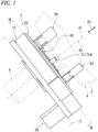
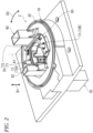
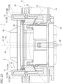
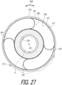
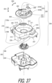
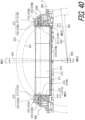
- a rotary connector apparatus 2 comprises a stator 10 and a rotator 20.
- the stator 10 is configured to be attached to a vehicle body 3.
- the rotator 20 is provided rotatably about a rotation axis A1 with respect to the stator 10.
- the stator 10 is configured to be fastened to a combination switch of the vehicle body 3.
- the rotator 20 is configured to rotate together with a steering 4 with respect to the stator 10.
- the steering 4 includes a steering wheel 5 and a steering shaft 6.
- the steering wheel 5 is fastened to an end portion of the steering shaft 6.
- the steering 4 is provided rotatably about a rotation axis A2 with respect to the vehicle body 3.
- the rotary connector apparatus 2 comprises a first electrical connector 30 and second electrical connectors 40 and 42.
- the first electrical connector 30 is attached to the stator 10.
- the second electrical connectors 40 and 42 are attached to the rotator 20.
- the first electrical connector 30 is configured to be electrically connected to electrical equipment (such as a control apparatus and a battery) provided in the vehicle body 3 (see, for example, FIG. 1 ), for example.
- the second electrical connectors 40 and 42 are configured to be electrically connected to a switch and the like of the steering wheel 5 and/or an electric circuit of an air bag apparatus and the like, for example.
- the stator 10 and the rotator 20 form a cable housing space 50 provided to surround the rotation axis A1.
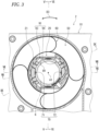
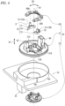
- the rotator 20 includes a rotator body 21.
- the stator 10 and the rotator body 21 form the cable housing space 50.
- the cable housing space 50 has an annular shape, and extends in a circumferential direction D3 with respect to the rotation axis A1.
- the rotary connector apparatus 2 further comprises an electrical cable 60 provided in the cable housing space 50.
- the electrical cable 60 is electrically connected to the first electrical connector 30 and the second electrical connector 40 ( FIG. 1 ).
- the electrical cable 60 has a flat shape with flexibility.
- the electrical cable 60 may also be referred to as a flexible flat cable.
- the electrical cable 60 includes a plurality of flat cables 61.
- the rotator body 21 includes a disk part 21A and a cylindrical part 21B.
- the disk part 21A includes a center opening 21C.
- the cylindrical part 21B extends in an axial direction D1 defined along the rotation axis A1 from the inner periphery portion of the disk part 21A.
- the rotator 20 includes a retainer 22.
- the retainer 22 is fastened to the rotator body 21.
- the retainer 22 is fastened to the cylindrical part 21B. With the rotator body 21 and the retainer 22, the rotator 20 is held rotatably about the rotation axis A1 with respect to the stator 10.
- the rotary connector apparatus 2 comprises an adjustment structure 9.
- the adjustment structure 9 is configured to allow the rotation axis A1 to move with respect to the vehicle body 3 in the state where the stator 10 is attached to the vehicle body 3.
- the adjustment structure 9 comprises a movable member 70.
- the movable member 70 is attached to the rotator 20 and is configured to transmit the rotation of the steering 4 to the rotator 20 (see, for example, FIG. 1 ).
- the movable member 70 is a separate member from the rotator 20 and is movably attached to the rotator 20.
- the movable member 70 is coupled to the steering wheel 5 (see, for example, FIG. 1 ) and is configured to receive the rotational force from the steering 4 (see, for example, FIG. 1 ).
- the movable member 70 includes a rotation input part 73 configured to receive the rotational force from the steering 4 (see, for example, FIG. 1 ).
- the movable member 70 includes a first movable body 71 and a second movable body 72.
- the rotation input part 73 includes a first rotation input part 73A and a second rotation input part 73B.
- the first movable body 71 includes the first rotation input part 73A.
- the second movable body 72 includes the second rotation input part 73B.
- the first movable body 71 is a separate member from the second movable body 72.
- the first movable body 71 may be formed integrally with the second movable body 72 as a one-piece member.
- the movable member 70 may include another movable body in addition to the first movable body 71 and the second movable body 72.
- the first movable body 71 includes a first movable part 74.
- the first rotation input part 73A protrudes from the first movable part 74 along the rotation axis A1.
- the second movable body 72 includes a second movable part 75.
- the second rotation input part 73B protrudes from the second movable part 75 along the rotation axis A1.
- the rotator 20 includes a holding member 80 attached to the rotator body 21.
- the movable member 70 is movably held between the rotator body 21 and the holding member 80.
- the first movable body 71 is movably held between the rotator body 21 and the holding member 80.
- the second movable body 72 is movably held between the rotator body 21 and the holding member 80.
- the holding member 80 is a separate member from the rotator body 21.
- the holding member 80 may be formed integrally with the rotator body 21 as a one-piece member.
- the holding member 80 may be divided into a plurality of parts.
- the holding member 80 includes a first opening 80A.
- the first rotation input part 73A extends through the first opening 80A.
- the holding member 80 includes a second opening 80B.
- the second rotation input part 73B extends through the second opening 80B.
- the stator 10, the rotator body 21, the retainer 22, the movable member 70, and the holding member 80 are each made of a non-metal material.
- the stator 10, the rotator body 21, the retainer 22, the movable member 70, and the holding member 80 are each made of resin.
- the material of each of the stator 10, the rotator body 21, the retainer 22, the movable member 70, and the holding member 80 may be a material other than resin.
- the steering wheel 5 includes a first protrusion 51A, a second protrusion 51B, and an intermediate member 51C.
- the first protrusion 51A and the second protrusion 51B are disposed spaced apart from each other in the circumferential direction D3.
- the rotation input part 73 is disposed between the first protrusion 51A and the second protrusion 51B in the circumferential direction D3.
- the intermediate member 51C is attached to the rotation input part 73, and is disposed between the first protrusion 51A and the second protrusion 51B.
- the intermediate member 51C includes an elastic member.
- the intermediate member 51C is made of rubber.
- the rotation of the steering wheel 5 is transmitted to the first rotation input part 73A of the first movable body 71 through the first protrusion 51A, the second protrusion 51B, and the intermediate member 51C.
- the intermediate member 51C may be included in the movable member 70 as a torque pin cap attached to the first rotation input part 73A.
- the steering wheel 5 includes a first protrusion 52A, a second protrusion 52B, and an intermediate member 52C.
- the first protrusion 52A and the second protrusion 52B are disposed spaced apart from each other in the circumferential direction D3.
- the rotation input part 73 is disposed between the first protrusion 52A and the second protrusion 52B in the circumferential direction D3.
- the intermediate member 52C is attached to the rotation input part 73, and is disposed between the first protrusion 52A and the second protrusion 52B.
- the intermediate member 52C includes an elastic member.
- the intermediate member 52C is made of rubber.
- the rotation of the steering wheel 5 is transmitted to the second rotation input part 73B of the second movable body 72 through the first protrusion 52A, the second protrusion 52B, and the intermediate member 52C.
- the intermediate member 52C may be included in the movable member 70 as a torque pin cap attached to the second rotation input part 73B.
- the rotator 20 includes a support structure 90.
- the support structure 90 movably supports the movable member 70 to change the angle of the rotation input part 73 with respect to the rotator 20 being changeable.
- the support structure 90 movably supports the first movable body 71 to change the angle of the first rotation input part 73A with respect to the rotator 20 being changeable.
- the support structure 90 movably supports the second movable body 72 to change the angle of the second rotation input part 73B with respect to the rotator 20 being changeable.
- the support structure 90 supports the movable member 70 movably within a predetermined range to change the angle of the rotation input part 73 with respect to the rotator 20 being changeable.
- the support structure 90 supports the first movable body 71 movably within a predetermined range to change the angle of the first rotation input part 73A with respect to the rotator 20 being changeable.
- the support structure 90 supports the second movable body 72 movably within a predetermined range to change the angle of the second rotation input part 73B with respect to the rotator 20 being changeable.
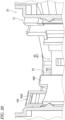
- the support structure 90 includes a first supporting body 91.
- the first supporting body 91 supports the movable member 70 movably along a first virtual sphere S1 centered at a reference point RP.
- the first supporting body 91 and the movable member 70 can have contact with each other on the first virtual sphere S1.
- the support structure 90 includes a second supporting body 92.
- the second supporting body 92 supports the movable member 70 movably along a second virtual sphere S2 centered at the reference point RP.
- the second supporting body 92 and the movable member 70 can have contact with each other on the second virtual sphere S2.
- the movable member 70 is disposed between the first supporting body 91 and the second supporting body 92.
- the first movable part 74 is movably held between first supporting part 93 and the holding member 80.
- the second movable part 75 is movably held between second supporting part 94 and the holding member 80.
- the first supporting body 91 includes a first supporting part 93 and a second supporting part 94.
- the first supporting part 93 supports the first movable body 71 movably along the first virtual sphere S1.
- the second supporting part 94 supports the second movable body 72 movably along the first virtual sphere S1.
- the second supporting body 92 includes a third supporting part 95 and a fourth supporting part 96.
- the third supporting part 95 supports the first movable body 71 movably along the second virtual sphere S2.
- the fourth supporting part 96 supports the second movable body 72 movably along the second virtual sphere S2.
- the first movable body 71 is movably held between the first supporting part 93 and the third supporting part 95.
- the second movable body 72 is movably held between the second supporting part 94 and the fourth supporting part 96.
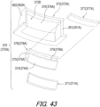
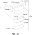
- the first movable body 71 includes a first contact part 76.
- the first contact part 76 can have contact with the first supporting part 93 of the first supporting body 91 on the first virtual sphere S1.
- the first contact part 76 is provided at the first movable part 74.
- the second movable body 72 includes a second contact part 77.
- the second contact part 77 can have contact with the second supporting part 94 of the first supporting body 91 on the first virtual sphere S1.
- the second contact part 77 is provided at the second movable part 75.
- the first movable body 71 includes a third contact part 78.
- the third contact part 78 can have contact with the third supporting part 95 of the second supporting body 92 on the second virtual sphere S2.
- the third contact part 78 is provided at the first movable part 74.
- the second movable body 72 includes a fourth contact part 79.
- the fourth contact part 79 can have contact with the fourth supporting part 96 of the second supporting body 92 on the second virtual sphere S2.
- the fourth contact part 79 is provided at the second movable part 75.
- the reference point RP is defined on the rotation axis A1.
- the first virtual sphere S1 has a first curvature radius R1 defined from the reference point RP.
- the second virtual sphere S2 has a second curvature radius R2 defined from the reference point RP.
- the second curvature radius R2 is larger than the first curvature radius R1.
- the reference point RP may be shifted from the rotation axis A1.
- the second curvature radius R2 may be smaller than the first curvature radius R1.
- the first supporting body 91 is provided at the rotator body 21.
- the second supporting body 92 is provided at the holding member 80.
- the first supporting body 91 may be provided at the holding member 80.
- the second supporting body 92 may be provided at the rotator body 21.
- At least one of the first supporting body 91 and the movable member 70 includes a first curved surface provided along the first virtual sphere S1.
- the first supporting body 91 includes first curved surfaces 93A and 94A provided along the first virtual sphere S1.
- the first supporting part 93 includes the first curved surface 93A.
- the second supporting part 94 includes the first curved surface 94A.
- the movable member 70 can have surface contact, line contact, and/or point contact with the first curved surfaces 93A and 94A.
- the first contact part 76 can have surface contact, line contact, and/or point contact with the first curved surface 93A.
- the second contact part 77 can have surface contact, line contact, and/or point contact with the first curved surface 94A.
- the movable member 70 can have surface contact and/or line contact with the first curved surfaces 93A and 94A.
- the first contact part 76 can have surface contact and/or line contact with the first curved surface 93A.
- the second contact part 77 can have surface contact and/or line contact with the first curved surface 94A.
- the manner of contact between the movable member 70 and the first supporting body 91 is not limited to the above-mentioned manner.
- first supporting body 91 and the movable member 70 may include the first curved surface.
- the movable member 70 (at least one of the first contact part 76 and the second contact part 77) may include the first curved surface, and the first supporting body 91 (at least one of the first supporting part 93 and the second supporting part 94) may have surface contact, line contact, and/or point contact with the first curved surface.
- the first curved surface may be composed of a combination of flat surfaces at least in part.
- At least one of the second supporting body 92 and the movable member 70 includes a second curved surface provided along the second virtual sphere S2.
- the second supporting body 92 includes second curved surfaces 95A and 96A provided along the second virtual sphere S2.
- the third supporting part 95 includes the second curved surface 95A.
- the fourth supporting part 96 includes the second curved surface 96A.
- the movable member 70 can have surface contact, line contact, and/or point contact with the second curved surfaces 95A and 96A.
- the third contact part 78 can have surface contact, line contact, and/or point contact with the second curved surface 95A.
- the fourth contact part 79 can have surface contact, line contact, and/or point contact with the second curved surface 96A.
- the movable member 70 can have surface contact and/or line contact with the second curved surfaces 95A and 96A.
- the third contact part 78 can have surface contact and/or line contact with the second curved surface 95A.
- the fourth contact part 79 can have surface contact and/or line contact with the second curved surface 96A.
- the manner of contact between the movable member 70 and the second supporting body 92 is not limited to the above-mentioned manner.
- the second supporting body 92 and the movable member 70 may include the second curved surface.
- the movable member 70 (at least one of the third contact part 78 and the fourth contact part 79) may include the second curved surface
- the second supporting body 92 (at least one of the third supporting part 95 and the fourth supporting part 96) may have surface contact, line contact, and/or point contact with the second curved surface.
- the second curved surface may be composed of a combination of flat surfaces at least in part.
- the first curved surface 93A extends in the circumferential direction D3.
- the first supporting part 93 includes at least one first recess 93B.
- the first supporting part 93 includes a plurality of the first recesses 93B.
- the first recess 93B is provided in the first curved surface 93A.
- the first recess 93B may be omitted from the first supporting part 93.
- the first curved surface 94A extends in the circumferential direction D3.
- the second supporting part 94 includes at least one second recess 94B.
- the second supporting part 94 includes a plurality of the second recesses 94B.
- the second recess 94B is provided in the first curved surface 94A.
- the second recess 94B may be omitted from the second supporting part 94.
- the first contact part 76 includes a plurality of first contact protrusions 76A, 76B, 76C, and 76D.
- the first contact protrusions 76A, 76B, 76C, and 76D protrude in the axial direction D1 from the first movable part 74 and extend in the circumferential direction D3.
- the first contact protrusions 76A, 76B, and 76C are disposed at approximately the same radial position, and are disposed spaced apart from each other in the circumferential direction D3.
- the first contact protrusion 76D is disposed radially outward of the first contact protrusion 76A, and is disposed spaced apart from the first contact protrusion 76A in the radial direction.
- the first contact protrusions 76A, 76B, 76C, and 76D may be formed as a single contact protrusion at least in part.
- the first contact part 76 may include a curved surface such as that of the first curved surface 93A.
- the first movable part 74 includes a first base 74A, and a plurality of first protruding parts 74B, 74C, and 74D.
- the first protruding parts 74B, 74C, and 74D protrude in the axial direction D1 from the first base 74A.
- the first contact protrusion 76A is provided at a first protruding part 74B, and protrudes in the axial direction D1 from the first protruding part 74B.
- the first contact protrusion 76B is provided at the first protruding part 74C, and protrudes in the axial direction D1 from the first protruding part 74C.
- the first contact protrusion 76C is provided at the first protruding part 74D, and protrudes in the axial direction D1 from the first protruding part 74D.
- the first movable body 71 includes a plurality of first grooves 71A and 71B.
- the first groove 71A is provided between the first protruding part 74B and 74C in the circumferential direction D3.
- the first groove 71B is provided between the first protruding part 74B and 74D in the circumferential direction D3.
- the second contact part 77 includes a plurality of second contact protrusions 77A, 77B, and 77C.
- the second contact protrusions 77A, 77B, and 77C protrude in the axial direction D1 from the second movable part 75, and extend in the circumferential direction D3.
- the second contact protrusions 77A and 77B are disposed at approximately the same radial position, and are disposed spaced apart from each other in the circumferential direction D3.
- the second contact protrusion 77C is disposed radially outward of the second contact protrusion 77A, and is disposed spaced apart from the second contact protrusion 77A in the radial direction.
- the second contact protrusions 77A, 77B, and 77C may be formed as a single contact protrusion at least in part.
- the second contact part 77 may include a curved surface such as that of the first curved surface 94A.
- the second movable part 75 includes a second base 75A, and a plurality of second protruding parts 75B and 75C.
- the second protruding parts 75B and 75C protrude in the axial direction D1 from the second base 75A.
- the second contact protrusion 77A is provided at the second protruding part 75B, and protrudes in the axial direction D1 from the second protruding part 75B.
- the second contact protrusion 77B is provided at the second protruding part 75C, and protrudes in the axial direction D1 from the second protruding part 75C.
- the second movable body 72 includes a second groove 72A.
- the second groove 72A is provided between the second protruding parts 75B and 75C in the circumferential direction D3.
- the first supporting part 93 includes first rotation receiving surfaces 93C and 93G and second rotation receiving surfaces 93D and 93H.
- the first rotation receiving surfaces 93C and 93G can have contact with the movable member 70 in the circumferential direction D3.
- the second rotation receiving surfaces 93D and 93H can have contact with the movable member 70 in the circumferential direction D3.
- the first rotation receiving surfaces 93C and 93G include a curved surface.
- the second rotation receiving surfaces 93D and 93H include a curved surface.
- the first supporting part 93 includes first rotation supporting parts 93E and 93F.
- the first rotation supporting part 93E includes a first rotation receiving surface 93C and a second rotation receiving surface 93D.
- the first rotation supporting part 93F includes a first rotation receiving surface 93G and a second rotation receiving surface 93H.
- one of the first rotation receiving surfaces 93C and 93G may be omitted, and another rotation receiving surface may be provided in addition to the first rotation receiving surfaces 93C and 93G.
- One of the second rotation receiving surfaces 93D and 93H may be omitted, and another rotation receiving surface may be provided in addition to the second rotation receiving surfaces 93D and 93H.
- the first movable body 71 includes first circumferential direction surfaces 71C and 71G and second circumferential direction surfaces 71D and 71H.
- the first circumferential direction surface 71C can have contact with the first rotation receiving surface 93C.
- the second circumferential direction surface 71D can have contact with the second rotation receiving surface 93D.
- the first circumferential direction surface 71G can have contact with the first rotation receiving surface 93G.
- the second circumferential direction surface 71D can have contact with the second rotation receiving surface 93D.
- the second circumferential direction surface 71H can have contact with the second rotation receiving surface 93H.
- the first circumferential direction surfaces 71C and 71G include a curved surface.
- the second circumferential direction surfaces 71D and 71H include a curved surface.
- the first protruding part 74B includes the first circumferential direction surface 71C and the second circumferential direction surface 71H.
- the first protruding part 74C includes the second circumferential direction surface 71D.
- the first protruding part 74D includes the first circumferential direction surface 71G.
- the first rotation supporting part 93E is provided between the first circumferential direction surface 71C and the second circumferential direction surface 71D in the circumferential direction D3.
- the first rotation supporting part 93F is provided between the first circumferential direction surface 71G and the second circumferential direction surface 71H in the circumferential direction D3.
- the first groove 71A is provided between the first circumferential direction surface 71C and the second circumferential direction surface 71D in the circumferential direction D3.
- the first groove 71B is provided between the first circumferential direction surface 71G and the second circumferential direction surface 71H in the circumferential direction D3.
- the second supporting part 94 includes a first rotation receiving surface 94C and a second rotation receiving surface 94D.
- the first rotation receiving surface 94C can have contact with the movable member 70 in the circumferential direction D3.
- the second rotation receiving surface 94D can have contact with the movable member 70 in the circumferential direction D3.
- the first rotation receiving surface 94C includes a curved surface.
- the second rotation receiving surface 94D includes a curved surface.
- the second supporting part 94 includes a first rotation supporting part 94E.
- the first rotation supporting part 94E includes the first rotation receiving surface 94C and the second rotation receiving surface 94D.
- another rotation receiving surface may be provided in addition to the first rotation receiving surface 94C.
- Another rotation receiving surface may be provided in addition to the second rotation receiving surface 94D.
- the second movable body 72 includes a first circumferential direction surface 72C and a second circumferential direction surface 72D.
- the first circumferential direction surface 72C can have contact with the first rotation receiving surface 94C.
- the second circumferential direction surface 72D can have contact with the second rotation receiving surface 94D.
- the first circumferential direction surface 72G can have contact with first rotation receiving surface 94G.
- the second circumferential direction surface 72D can have contact with the second rotation receiving surface 94D.
- the first circumferential direction surface 72C includes a curved surface.
- the second circumferential direction surface 72D includes a curved surface.
- the second protruding part 75B includes the first circumferential direction surface 72C and a second circumferential direction surface 72H.
- the second protruding part 75C includes the second circumferential direction surface 72D.
- the second protruding part 75D includes the first circumferential direction surface 72G.
- the first rotation supporting part 94E is provided between the first circumferential direction surface 72C and the second circumferential direction surface 72D in the circumferential direction D3.
- the first rotation supporting part 94F is provided between the first circumferential direction surface 72G and the second circumferential direction surface 72H in the circumferential direction D3.
- the second groove 72A is provided between the first circumferential direction surface 72C and the second circumferential direction surface 72D in the circumferential direction D3.
- the second curved surface 95A extends in the circumferential direction D3.
- the second curved surface 96A extends in the circumferential direction D3.
- the second curved surface 95A is coupled to the second curved surface 96A.
- the holding member 80 includes a first holding part 81 and a second holding part 82.
- the second curved surface 95A is provided at the first holding part 81.
- the second curved surface 96A is provided at the second holding part 82.
- the first holding part 81 is coupled to the second holding part 82.
- the holding member 80 includes the center opening 80C and an inner peripheral edge 80D.
- the inner peripheral edge 80D defines the center opening 80C.
- the second curved surfaces 95A and 96A extend along the inner peripheral edge 80D.
- the third contact part 78 includes a plurality of third contact protrusions 78A, 78B, and 78C.
- the third contact protrusions 78A, 78B, and 78C protrude in the axial direction D1 from the first movable part 74, and extend in the circumferential direction D3.
- the third contact protrusions 78A, 78B, and 78C protrude in the axial direction D1 from the first base 74A.
- the third contact protrusions 78B and 78C are disposed at approximately the same radial position, and are disposed spaced apart from each other in the circumferential direction D3.
- the third contact protrusions 78B and 78C are disposed radially outward of the third contact protrusion 78A, and are disposed spaced apart from the third contact protrusion 78A in the radial direction.
- the third contact protrusions 78A, 78B, and 78C may be formed as a single contact protrusion at least in part.
- the third contact part 78 may include a curved surface such as that of the second curved surface 95A.
- the fourth contact part 79 includes a plurality of fourth contact protrusions 79A and 79B.
- the fourth contact protrusions 79A and 79B protrude in the axial direction D1 from the second movable part 75, and extend in the circumferential direction D3.
- the fourth contact protrusions 79A and 79B protrude in the axial direction D1 from the second base 75A.
- the fourth contact protrusion 79B is disposed radially outward of the fourth contact protrusion 79A, and is disposed spaced apart from the fourth contact protrusion 79A in the radial direction.
- the fourth contact protrusions 79A and 79B may be formed as a single contact protrusion at least in part.
- the fourth contact part 79 may include a curved surface such as that of the second curved surface 96A.
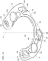
- the rotator body 21 includes a plurality of attaching parts 103, 104, 105, and 106.
- the holding member 80 includes a plurality of engaging portions 83, 84, 85, and 86.
- the engaging portions 83, 84, 85, and 86 are configured to engage with the rotator body 21.
- the engaging portion 83 is configured to engage with the attaching part 103.
- the engaging portion 84 is configured to engage with the attaching part 104.
- the engaging portion 85 is configured to engage with the attaching part 105.
- the engaging portion 86 is configured to engage with the attaching part 106.
- the holding member 80 may be attached to the rotator body 21 with a structure other than the above-mentioned structure.
- the holding member 80 may be fastened to the rotator body 21 with a fixing member such as a screw.
- the engaging portion 83 includes an opening 83A and an engaging claw 83B.
- the engaging claw 83B protrudes from the inner peripheral edge of the opening 83A.
- the engaging portion 84 includes an opening 84A and an engaging claw 84B.
- the engaging claw 84B protrudes from the inner peripheral edge of the opening 84A.
- the engaging portion 85 includes an opening 85A and an engaging claw 85B.
- the engaging claw 85B protrudes from the inner peripheral edge of the opening 85A.
- the engaging portion 86 includes an opening 86A and an engaging claw 86B.
- the engaging claw 86B protrudes from the inner peripheral edge of the opening 86A.
- the attaching part 103 includes an attaching opening 103A.
- the engaging portion 83 see, for example, FIG. 15
- the engaging claw 83B see, for example, FIG. 15
- the attaching part 104 includes an attaching opening 104A.
- the engaging claw 84B see, for example, FIG. 15
- the attaching opening 104A is fitted into the attaching opening 104A.
- the attaching part 105 includes an attaching opening 105A.
- the engaging portion 85 see, for example, FIG. 15
- the engaging claw 85B see, for example, FIG. 15
- the attaching part 106 includes an attaching opening 106A.
- the engaging claw 86B see, for example, FIG. 15
- the attaching opening 106A is fitted into the attaching opening 106A.
- the rotary connector apparatus 2 comprises the stator 10, the rotator 20, and the movable member 70.
- the stator 10 is configured to be fastened to the vehicle body 3.
- the rotator 20 is provided rotatably about the rotation axis A1 with respect to the stator 10.
- the movable member 70 is attached to the rotator 20 and is configured to transmit the rotation of the steering 4 to the rotator 20.
- the stator 10 and the rotator 20 form the cable housing space 50 provided to surround the rotation axis A1.
- the movable member 70 includes the rotation input part 73 configured to receive the rotational force from the steering 4.
- the rotator 20 includes the support structure 90 movably supporting the movable member 70 to change the angle of the rotation input part 73 with respect to the rotator 20 being changeable.
- the support structure 90 movably supports the movable member 70 to change the angle of the rotation input part 73 with respect to the rotator 20 being changeable, and thus even when the rotation axis A2 of the steering 4 is tilted with respect to the rotation axis A1 of the rotary connector apparatus 2, the rotation input part 73 of the movable member 70 can follow the inclination of the rotation axis A2 of the steering 4 in a predetermined range (for example, 2 degrees). Thus, the influence of the declination of the steering 4 can be reduced.
- the rotary connector apparatus 2 comprises the stator 10, the rotator 20, and the adjustment structure 9.
- the stator 10 is configured to be attached to the vehicle body 3.
- the rotator 20 is provided rotatably about the rotation axis A1 with respect to the stator 10.
- the adjustment structure 9 is configured to allow the rotation axis A1 to move with respect to the vehicle body 3 in the state where the stator 10 is attached to the vehicle body 3.
- the stator 10 and the rotator 20 form the cable housing space 50 provided to surround the rotation axis A1.
- the rotation axis A1 can move with respect to the vehicle body 3 with the adjustment structure 9, and thus the influence of at least one of the declination or eccentricity and the steering 4 can be reduced with a simple structure.
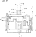
- a steering apparatus 201 is an apparatus for changing the traveling direction of the vehicle, and is provided rotatably with respect to the vehicle body 3.
- the steering apparatus 201 comprises a supporting member 203 and a rotary connector apparatus 204.
- the supporting member 203 is included in the vehicle body 3.
- the supporting member 203 includes a housing for a combination switch, for example.
- the steering apparatus 201 includes the steering 4.
- the steering 4 is provided rotatably about a rotation axis A22 with respect to the supporting member 203.
- the steering 4 includes the steering wheel 5 and the steering shaft 6.
- the steering wheel 5 is fastened to an end portion of the steering shaft 6.
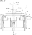
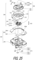
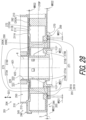
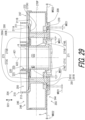
- the rotary connector apparatus 204 comprises a stator 210 and a rotator 220.
- the stator 210 is configured to be coupled to the vehicle body 3.
- the stator 210 is configured to be coupled to the supporting member 203.
- the rotator 220 is provided rotatably about the rotation axis A21 with respect to the stator 210.
- the rotator 220 is coupled to the steering 4 and is configured to rotate about the rotation axis A21 together with the steering 4 with respect to the stator 210.
- the rotary connector apparatus 204 comprises a first electrical connector 230 and second electrical connectors 240 and 242.
- the first electrical connector 230 is attached to the stator 210.
- the second electrical connectors 240 and 242 are attached to the rotator 220.
- the first electrical connector 230 is configured to be electrically connected to electrical equipment (such as a control apparatus and a battery) provided in the vehicle body 3, for example.
- the second electrical connectors 240 and 242 are configured to be electrically connected to a switch and the like of the steering wheel 5 and/or an electric circuit of an air bag apparatus and the like, for example.
- the supporting member 203 comprises a supporting body 244 and a cover 245.
- the cover 245 is configured to be attached to the supporting body 244.
- the cover 245 includes a first cover 246 and a second cover 247.
- the first cover 246 is a separate member from the second cover 247.
- the cover 245 includes an opening 245A.
- the stator 210 is disposed in the opening 245A in the state where the stator 210 and the cover 245 are attached to the supporting body 244.
- the opening 245A is defined by the first cover 246 and the second cover 247.
- the stator 210 includes a baseplate 211, an outer periphery wall 212, and a cover 213.
- the baseplate 211 includes a center opening 211C.
- the outer periphery wall 212 extends from the baseplate 211 in an axial direction D21 defined along the rotation axis A21.
- the cover 213 is coupled to the baseplate 211 and the outer periphery wall 212 with the cover 213 covering the cable path from the outer periphery wall 212 to the first electrical connector 230.
- the rotator 220 includes a rotator body 221, a sleeve 222, and a rotation input part 223.
- the sleeve 222 is fastened to the rotator body 221. With the rotator body 221 and the sleeve 222, the rotator 220 is held rotatably about the rotation axis A21 with respect to the stator 210.
- the rotation input part 223 protrudes from the rotator body 221 in the axial direction D21.
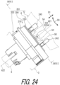
- the rotation input part 223 is configured to receive the rotational force from the steering 4 (see, for example, FIG. 24 ).
- the rotation input part 223 includes a first rotation input part 223A and a second rotation input part 223B.
- the first rotation input part 223A protrudes from the rotator body 221 in the axial direction D21.
- the second rotation input part 223B protrudes from the rotator body 221 in the axial direction D21.
- the steering wheel 5 includes a first protrusion 5A, a second protrusion 5B, and an intermediate member 5C.
- the first protrusion 5A and the second protrusion 5B are disposed spaced apart from each other in a circumferential direction D23.
- the first rotation input part 223A is disposed between the first protrusion 5A and the second protrusion 5B in the circumferential direction D23.
- the intermediate member 5C is attached to the first rotation input part 223A, and is disposed between the first protrusion 5A and the second protrusion 5B.
- the intermediate member 5C includes an elastic member.
- the intermediate member 5C is made of rubber.
- the rotation of the steering wheel 5 is transmitted to the first rotation input part 223A of the rotator 220 through the first protrusion 5A, the second protrusion 5B, and the intermediate member 5C.
- the intermediate member 5C may be included in the rotator 220 as a torque pin cap attached to the first rotation input part 223A.
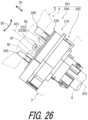
- the steering wheel 5 includes a first protrusion 5D, a second protrusion 5E, and an intermediate member 5F.
- the first protrusion 5D and the second protrusion 5E are disposed spaced apart from each other in the circumferential direction D23.
- the second rotation input part 223B is disposed between the first protrusion 5D and the second protrusion 5E in the circumferential direction D23.
- the intermediate member 5F is attached to the second rotation input part 223B, and is disposed between the first protrusion 5D and the second protrusion 5E.
- the intermediate member 5F includes an elastic member.
- the intermediate member 5F is made of rubber.
- the rotation of the steering wheel 5 is transmitted to the second rotation input part 223B of the rotator 220 through the first protrusion 5D, the second protrusion 5E, and the intermediate member 5F.
- the intermediate member 5F may be included in the rotator 220 as a torque pin cap attached to the second rotation input part 223B.
- the stator 210 and the rotator 220 form a cable housing space 250 provided to surround the rotation axis A21.
- the cable housing space 250 has an annular shape, and extends in the circumferential direction D23 with respect to the rotation axis A21.
- the rotary connector apparatus 204 further comprises an electrical cable 260 provided in the cable housing space 250.
- the electrical cable 260 is electrically connected to the first electrical connector 230 and the second electrical connectors 240 and 242 (see, for example, FIG. 25 ).
- the electrical cable 260 has a flat shape with flexibility.
- the electrical cable 260 may also be referred to as a flexible flat cable.
- the electrical cable 260 includes a plurality of flat cables 261.
- the rotary connector apparatus 204 comprises an adjustment structure 209.
- the adjustment structure 209 is configured to allow the rotation axis A21 to move with respect to the vehicle body 3 in the state where the stator 210 is attached to the vehicle body 3.
- the adjustment structure 209 includes a coupling structure 270.
- the coupling structure 270 is configured to couple the stator 210 to the vehicle body 3.
- the coupling structure 270 is configured to couple the stator 210 to the supporting member 203 of the vehicle body 3.
- the coupling structure 270 is configured to movably couple the stator 210 to the supporting member 203 of the vehicle body 3.
- the coupling structure 270 can have contact with the vehicle body 3 to restrict the movement of the stator 210 with respect to the vehicle body 3 in the axial direction D21 defined along the rotation axis A21 and to allow the stator 210 to move with respect to the vehicle body 3 along a virtual plane 270P perpendicular to the rotation axis A21 in the state where the coupling structure 270 couples the stator 210 to the vehicle body 3.
- the coupling structure 270 can have contact with the supporting member 203 to restrict the movement of the stator 210 with respect to the supporting member 203 in the axial direction D21 and to allow the stator 210 to move with respect to the supporting member 203 along the virtual plane 270P in the state where the coupling structure 270 couples the stator 210 to the supporting member 203.
- the coupling structure 270 includes a first sliding part 271 slidable with the vehicle body 3.
- the first sliding part 271 is slidable with the supporting member 203.
- the first sliding part 271 is disposed spaced apart from the stator 210 in the axial direction D21.
- at least a part of the supporting member 203 is disposed between the stator 210 and the first sliding part 271 in the axial direction D21.
- the coupling structure 270 includes a second sliding part 272 slidable with the vehicle body 3.
- the second sliding part 272 is disposed at a position different from that of the first sliding part 271 in the axial direction D21.
- the second sliding part 272 is disposed spaced apart from the first sliding part 271 in the axial direction D21.
- the second sliding part 272 is provided at the stator 210.
- the second sliding part 272 is provided at the baseplate 211 of the stator 210.
- the baseplate 211 includes a first surface 211A and a second surface 211B.
- the second surface 211B is provided on the rear side of the first surface 211A in the axial direction D21.
- the outer periphery wall 212 extends from the first surface 211A of the baseplate 211 in the axial direction D21.
- the second sliding part 272 is provided at the second surface 211B of the baseplate 211.
- the second sliding part 272 includes a second sliding surface 272A.
- the second sliding surface 272A is included in the second surface 211B of the baseplate 211.
- the second sliding part 272 may be provided at another portion of the stator 210 and a member other than the stator 210.
- the coupling structure 270 includes a coupling member 273.
- the coupling member 273 extends from the stator 210 in the axial direction D21.
- the first sliding part 271 is provided at an end portion of the coupling member 273 and protrudes along the virtual plane 270P from the coupling member 273.
- the coupling member 273 extends from the stator 210 in a direction away from the cable housing space 250 in the axial direction D21.
- the coupling member 273 is provided integrally with the stator 210 as a one-piece member.
- the first sliding part 271 is a separate member from the stator 210 and the coupling member 273.
- the first sliding part 271 may be provided integrally with at least one of the stator 210 and the coupling member 273 as a one-piece member.
- the coupling member 273 may be a separate member from the stator 210.
- the coupling member 273 includes at least one coupling rod 273A, 273B, 273C, and/or 273D extending from the stator 210 in the axial direction D21.
- the coupling member 273 includes a plurality of the coupling rods 273A, 273B, 273C, and 273D extending from the stator 210 in the axial direction D21.
- the total number of the coupling rods 273A, 273B, 273C, and 273D is not limited to four.
- the structure of the coupling member 273 is not limited to the coupling rods 273A, 273B, 273C, and 273D.
- the first sliding part 271 includes at least one restriction plate 274A, 274B, 274C, and/or 274D attached to the at least one coupling rod 273A, 273B, 273C, and/or 273D, respectively.
- the first sliding part 271 includes a plurality of the restriction plates 274A, 274B, 274C, and 274D attached to the plurality of coupling rods 273A, 273B, 273C, and 273D, respectively.
- the total number of the restriction plates is not limited to four.
- the structure of the first sliding part 271 is not limited to the restriction plates 274A, 274B, 274C, and 274D.
- the at least one restriction plate 274A, 274B, 274C, and/or 274D protrudes along the virtual plane 270P from the at least one coupling rod 273A, 273B, 273C, and/or 273D, respectively.
- the plurality of restriction plates 274A, 274B, 274C, and 274D protrude along the virtual plane 270P from the plurality of coupling rods 273A, 273B, 273C, and 273D, respectively.
- the first sliding part 271 includes at least one first sliding surface 271A, 271B, 271C, and/or 271D.
- the at least one first sliding surface 271A, 271B, 271C, and/or 271D is provided at the at least one restriction plate 274A, 274B, 274C, and/or 274D, respectively.
- a plurality of the first sliding surfaces 271A, 271B, 271C, and 271D is provided at the plurality of restriction plates 274A, 274B, 274C, and 274D, respectively.
- the total number of the first sliding surfaces is not limited to four.
- the first sliding surfaces 271A, 271B, 271C, and 271D may be provided at portions other than the restriction plates 274A, 274B, 274C, and 274D.
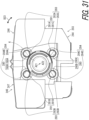
- the supporting member 203 includes an opening 280, and a first supporting part 281 provided at a periphery of the opening 280.
- the coupling structure 270 is inserted into the opening 280 in the state where the coupling structure 270 couples the stator 210 to the supporting member 203.
- the coupling structure 270 can have contact with the first supporting part 281 to restrict the movement of the stator 210 with respect to the supporting member 203 in the axial direction D21 and to allow the stator 210 to move with respect to the supporting member 203 along the virtual plane 270P in the state where the coupling structure 270 couples the stator 210 to the supporting member 203.
- the position of the virtual plane 270P illustrated in the drawing is merely an example, and the virtual plane 270P may be defined at a position other than the position illustrated in the drawing.
- the opening 280 includes at least one opening 280A, 280B, 280C, and/or 280D.
- the first supporting part 281 includes at least one first supporting part 281A, 281B, 281C, and/or 281D.
- the opening 280 includes a plurality of the openings 280A, 280B, 280C, and 280D.
- the first supporting part 281 includes a plurality of the first supporting parts 281A, 281B, 281C, and 281D.
- the total number of the openings is not limited to four.
- the total number of the first supporting parts is not limited to four.
- the coupling member 273 is inserted into the opening 280 in the state where the coupling structure 270 couples the stator 210 to the supporting member 203.
- the coupling rod 273A is each inserted into the opening 280A in the state where the coupling structure 270 couples the stator 210 to the supporting member 203.
- the coupling rod 273B is each inserted into the opening 280B in the state where the coupling structure 270 couples the stator 210 to the supporting member 203.
- the coupling rod 273C is each inserted into the opening 280C in the state where the coupling structure 270 couples the stator 210 to the supporting member 203.
- the coupling rod 273D is each inserted into the opening 280D in the state where the coupling structure 270 couples the stator 210 to the supporting member 203.
- the first sliding part 271 is slidable with the first supporting part 281.
- the first sliding surface 271A is slidable with the first supporting part 281A.
- the first sliding surface 271B is slidable with the first supporting part 281B.
- the first sliding surface 271C is slidable with the first supporting part 281C.
- the first sliding surface 271D is slidable with the first supporting part 281D.
- the first supporting part 281A is provided on the outer periphery side of the opening 280A, and is disposed surrounding the opening 280A.
- the first supporting part 281B is provided on the outer periphery side of the opening 280B, and is disposed surrounding the opening 280B.
- the first supporting part 281C is provided on the outer periphery side of the opening 280C, and is disposed surrounding the opening 280C.
- the first supporting part 281D is provided on the outer periphery side of the opening 280D, and is disposed surrounding the opening 280D.
- the first supporting parts 281A, 281B, 281C, and 281D protrude in the axial direction D21.
- the supporting member 203 includes a second supporting part 282.
- the second supporting part 282 includes at least one second supporting part 282A, 282B, 282C, 282D, 282E, and/or 282F.
- the second supporting part 282 includes a plurality of the second supporting parts 282A, 282B, 282C, 282D, 282E, and 282F.
- the second supporting parts 282A, 282B, 282C, 282D, 282E, and 282F are disposed spaced apart from each other in the circumferential direction D23.
- the total number of the second supporting parts is not limited to six.
- the arrangement of the second supporting parts 282A, 282B, 282C, 282D, 282E, and 282F is not limited to the arrangement illustrated in FIG. 32 .
- the second sliding part 272 is slidable with the second supporting part 282.
- the second sliding surface 272A is slidable with the second supporting part 282.
- the second sliding part 272 is slidable with the plurality of second supporting parts 282A, 282B, 282C, 282D, 282E, and 282F.
- the second sliding surface 272A is slidable with the plurality of second supporting parts 282A, 282B, 282C, 282D, 282E, and 282F.
- the coupling structure 270 can have contact with the vehicle body 3 to restrict the movement of the stator 210 with respect to the vehicle body 3 along the virtual plane 270P perpendicular to the rotation axis A21 within a first movable range MR21 in the state where the coupling structure 270 couples the stator 210 to the vehicle body 3.
- the coupling structure 270 can have contact with the supporting member 203 to restrict the movement of the stator 210 with respect to the supporting member 203 along the virtual plane 270P within the first movable range MR21 in the state where the coupling structure 270 couples the stator 210 to the supporting member 203.
- the first movable range MR21 represents the movable range of the stator 210 with respect to the supporting member 203 along the virtual plane 270P, with a state where the rotation axis A21 of the rotary connector apparatus 204 coincides with the rotation axis A2 of the steering 4 as a reference.
- the first movable range MR21 is defined in the radial direction with respect to the rotation axis A21.
- the coupling structure 270 can have contact with the vehicle body 3 to restrict the movement of the stator 210 with respect to the vehicle body 3 within a second movable range MR22 in the axial direction D21 in the state where the coupling structure 270 couples the stator 210 to the vehicle body 3.
- the coupling structure 270 can have contact with the supporting member 203 to restrict the movement of the stator 210 with respect to the supporting member 203 within the second movable range MR22 in the axial direction D21 in the state where the coupling structure 270 couples the stator 210 to the supporting member 203.
- the second movable range MR22 is defined by the axial direction D21.
- the first movable range MR21 is larger than the second movable range MR22.
- the second movable range MR22 is defined by the first sliding part 271, the second sliding part 272, the first supporting part 281, and the second supporting part 282.
- the supporting member 203 includes a first restriction part 283.
- the first restriction part 283 can have contact with the first sliding part 271.
- the first restriction part 283 can have contact with the restriction plates 274A, 274B, 274C, and 274D.
- the first restriction part 283 includes a plurality of first restriction surfaces 283A, 283B, 283C, and 283D.
- the restriction plate 274A can have contact with the first restriction surface 283A.
- the restriction plate 274B can have contact with the first restriction surface 283B.
- the restriction plate 274C can have contact with the first restriction surface 283C.
- the restriction plate 274D can have contact with the first restriction surface 283D.
- the first restriction surface 283A is provided between the restriction plate 274A and the rotation axis A21 in the radial direction.
- the first restriction surface 283B is provided between the restriction plate 274B and the rotation axis A21 in the radial direction.
- the first restriction surface 283C is provided between the restriction plate 274C and the rotation axis A21 in the radial direction.
- the first restriction surface 283D is provided between the restriction plate 274D and the rotation axis A21 in the radial direction.
- the coupling structure 270 can have contact with the vehicle body 3 to restrict the rotation of the stator 210 about the rotation axis A21 with respect to the vehicle body 3 in the state where the coupling structure 270 couples the stator 210 to the vehicle body 3.
- the coupling structure 270 can have contact with the supporting member 203 to restrict the rotation of the stator 210 about the rotation axis A21 with respect to the supporting member 203 within a predetermined rotation range MR23 in the state where the coupling structure 270 couples the stator 210 to the supporting member 203.
- the supporting member 203 includes a second restriction part 284.
- the second restriction part 284 can have contact with the first sliding part 271.
- the first sliding part 271 can have contact with the second restriction part 284 to restrict the rotation of the stator 210 about the rotation axis A21 with respect to the vehicle body 3 in the state where the coupling structure 270 couples the stator 210 to the supporting member 203.
- the first sliding part 271 can have contact with the second restriction part 284 to restrict the rotation of the stator 210 about the rotation axis A21 with respect to the vehicle body 3 within the predetermined rotation range MR23 in the state where the coupling structure 270 couples the stator 210 to the supporting member 203.
- the second restriction part 284 can have contact with the restriction plates 274A, 274B, 274C, and 274D.
- the second restriction part 284 includes a plurality of second restriction surfaces 284A, 284B, 284C, and 284D.
- the restriction plate 274A can have contact with the second restriction surface 284A when the stator 210 rotates about the rotation axis A21 with respect to the supporting member 203.
- the restriction plate 274B can have contact with the second restriction surface 284B when the stator 210 rotates about the rotation axis A21 with respect to the supporting member 203.
- the restriction plate 274C can have contact with the second restriction surface 284C when the stator 210 rotates about the rotation axis A21 with respect to the supporting member 203.
- the restriction plate 274D can have contact with the second restriction surface 284D when the stator 210 rotates about the rotation axis A21 with respect to the supporting member 203.
- the rotation range MR23 is defined by the restriction plates 274A, 274B, 274C, and 274D and the second restriction surfaces 284A, 284B, 284C, and 284D.
- the second restriction surface 284A is provided to surround the restriction plate 274A.
- the second restriction surface 284B is provided to surround the restriction plate 274B.
- the second restriction surface 284C is provided to surround the restriction plate 274C.
- the second restriction surface 284D is provided to surround the restriction plate 274D.
- the arrangement of the second restriction surfaces 284A, 284B, 284C, and 284D is not limited to the arrangement of the present embodiment.
- the rotary connector apparatus 204 comprises the stator 210, the rotator 220, and the coupling structure 270.
- the rotator 220 is provided rotatably about the rotation axis A21 with respect to the stator 210.
- the coupling structure 270 is configured to couple the stator 210 to the vehicle body 3.
- the stator 210 and the rotator 220 form the cable housing space 250 provided to surround the rotation axis A21.
- the coupling structure 270 can have contact with the vehicle body 3 to restrict the movement of the stator 210 with respect to the vehicle body 3 in the axial direction D21 defined along the rotation axis A21 and to allow the stator 210 to move with respect to the vehicle body 3 along the virtual plane 270P perpendicular to the rotation axis A21 in the state where the coupling structure 270 couples the stator 210 to the vehicle body 3.
- the load at the coupling part between the rotation input part 223 (for example, at least one of the first rotation input part 223A and the second rotation input part 223B illustrated in FIGS. 24 to 26 ) and the steering 4 (for example, the steering wheel 5 illustrated in FIGS. 24 and 26 ) increases, and consequently abnormal noise may be generated from the coupling part or the coupling part may be damaged.
- the stator 210 follows the eccentricity of the steering 4, and thus the rotator 220 can also follow the eccentricity of the steering 4.
- the load that acts on the coupling part between the rotation input part 223 and the steering wheel 5 can be reduced.
- the influence of the eccentricity of the steering 4 can be reduced with a simple structure.
- the rotary connector apparatus 204 comprises the stator 210, the rotator 220, and the adjustment structure 209.
- the stator 210 is configured to be attached to the vehicle body 3.
- the rotator 220 is provided rotatably about the rotation axis A21 with respect to the stator 210.
- the adjustment structure 209 is configured to allow the rotation axis A21 to move with respect to the vehicle body 3 in the state where the stator 210 is attached to the vehicle body 3.
- the stator 210 and the rotator 220 form the cable housing space 250 provided to surround the rotation axis A21.
- the adjustment structure 209 allows the rotation axis A21 to move with respect to the vehicle body 3, and thus the influence of at least one of the declination and eccentricity of the steering 4 can be reduced with a simple structure.
- a steering apparatus 301 is an apparatus for changing the traveling direction of the vehicle, and is provided rotatably with respect to the vehicle body 3.
- the steering apparatus 301 comprises a base member 303 and a rotary connector apparatus 304.
- the base member 303 is included in the vehicle body 3.
- the base member 303 includes a housing for a combination switch, for example.
- the steering apparatus 301 includes the steering 4.
- the steering 4 is provided rotatably about a rotation axis A32 with respect to the base member 303.
- the steering 4 includes the steering wheel 5 and the steering shaft 6.
- the steering wheel 5 is fastened to an end portion of the steering shaft 6.
- the rotary connector apparatus 304 comprises a stator 310 and a rotator 320.
- the stator 310 is configured to be coupled to the vehicle body 3.
- the stator 310 is configured to be coupled to the base member 303.
- the rotator 320 is provided rotatably about a rotation axis A31 with respect to the stator 310.
- the rotator 320 is coupled to the steering 4 and is configured to rotate about the rotation axis A31 together with the steering 4 with respect to the stator 310.
- the rotary connector apparatus 304 comprises a first electrical connector 330 and second electrical connectors 340 and 342.
- the first electrical connector 330 is attached to the stator 310.
- the second electrical connectors 340 and 342 are attached to the rotator 320.
- the first electrical connector 330 is configured to be electrically connected to electrical equipment (such as a control apparatus and a battery) provided in the vehicle body 3, for example.
- the second electrical connectors 340 and 342 are configured to be electrically connected to a switch and the like of the steering wheel 5 and/or an electric circuit of an air bag apparatus and the like, for example.
- the base member 303 comprises a base 244 and a cover 345.
- the cover 345 is configured to be attached to the base 244. As illustrated in FIGS. 37 and 42 , the cover 345 includes a first cover 346 and a second cover 347. The first cover 346 is a separate member from the second cover 347.
- the cover 345 includes an opening 345A.
- the stator 310 is disposed in the opening 345A in the state where the stator 310 and the cover 345 are attached to the base 244.
- the opening 345A is defined by the first cover 346 and the second cover 347.
- the stator 310 includes a baseplate 311, an outer periphery wall 312, and a cover part 313.
- the baseplate 311 includes a center opening 311C.
- the outer periphery wall 312 extends from the baseplate 311 in an axial direction D31 defined along the rotation axis A31.
- the cover part 313 is coupled to the baseplate 311 and the outer periphery wall 312 with the cover part 313 covering the cable path from the outer periphery wall 312 to the first electrical connector 330.
- the rotator 320 includes a rotator body 321, a sleeve 322, and a rotation input part 323.
- the sleeve 322 is fastened to the rotator body 321. With the rotator body 321 and the sleeve 322, the rotator 320 is held rotatably about the rotation axis A31 with respect to the stator 310.
- the rotation input part 323 protrudes in the axial direction D31 from the rotator body 321.
- the rotation input part 323 is configured to receive the rotational force from the steering 4 (see, for example, FIG. 36 ).
- the rotation input part 323 includes a first rotation input part 323A and a second rotation input part 323B.
- the first rotation input part 323A protrudes in the axial direction D31 from the rotator body 321.
- the second rotation input part 323B protrudes in the axial direction D31 from the rotator body 321.
- the steering wheel 5 includes the first protrusion 5A, the second protrusion 5B, and the intermediate member 5C.
- the first protrusion 5A and the second protrusion 5B are disposed spaced apart from each other in a circumferential direction D33.
- the first rotation input part 323A is disposed between the first protrusion 5A and the second protrusion 5B in the circumferential direction D33.
- the intermediate member 5C is attached to the first rotation input part 323A, and is disposed between the first protrusion 5A and the second protrusion 5B.
- the intermediate member 5C includes an elastic member.
- the intermediate member 5C is made of rubber.
- the rotation of the steering wheel 5 is transmitted to the first rotation input part 323A of the rotator 320 through the first protrusion 5A, the second protrusion 5B, and the intermediate member 5C.
- the intermediate member 5C may be included in the rotator 320 as a torque pin cap attached to the first rotation input part 323A.
- the steering wheel 5 includes the first protrusion 5D, the second protrusion 5E, and the intermediate member 5F.
- the first protrusion 5D and the second protrusion 5E are disposed spaced apart from each other in the circumferential direction D33.
- the second rotation input part 323B is disposed between the first protrusion 5D and the second protrusion 5E in the circumferential direction D33.
- the intermediate member 5F is attached to the second rotation input part 323B, and is disposed between the first protrusion 5D and the second protrusion 5E.
- the intermediate member 5F includes an elastic member.
- the intermediate member 5F is made of rubber.
- the rotation of the steering wheel 5 is transmitted to the second rotation input part 323B of the rotator 320 through the first protrusion 5D, the second protrusion 5E, and the intermediate member 5F.
- the intermediate member 5F may be included in the rotator 320 as a torque pin cap attached to the second rotation input part 323B.
- the stator 310 and the rotator 320 form a cable housing space 350 provided to surround the rotation axis A31.
- the cable housing space 350 has an annular shape, and extends in the circumferential direction D33 with respect to the rotation axis A31.
- the rotary connector apparatus 304 further comprises the electrical cable 60 provided in the cable housing space 350.
- the electrical cable 60 is electrically connected to the first electrical connector 330 and the second electrical connectors 340 and 342 (see, for example, FIG. 37 ).
- the electrical cable 60 has a flat shape with flexibility.
- the electrical cable 60 may also be referred to as a flexible flat cable.
- the electrical cable 60 includes a plurality of flat cables 61.
- the rotary connector apparatus 304 comprises an adjustment structure 309.
- the adjustment structure 309 is configured to allow the rotation axis A31 to move with respect to the vehicle body 3 in the state where the stator 310 is attached to the vehicle body 3.
- the adjustment structure 309 includes a coupling structure 370.
- the coupling structure 370 is configured to couple the stator 310 to the vehicle body 3.
- the coupling structure 370 is configured to couple the stator 310 to the base member 303 of the vehicle body 3.
- the coupling structure 370 is configured to movably couple the stator 310 to the base member 303 of the vehicle body 3.
- the coupling structure 370 restricts the movement of the stator 310 with respect to the base member 303 of the vehicle body 3 in the axial direction D31, and allows the stator 310 to move with respect to the base member 303 of the vehicle body 3 in a direction other than the axial direction D31 within a predetermined movable range in the state where the coupling structure 370 couples the stator 310 to the vehicle body 3.
- the coupling structure 370 supports the stator 310 movably with respect to vehicle body 3 to change the angle of the rotation axis A31 with respect to the vehicle body 3 in the state where the coupling structure 370 couples the stator 310 to the vehicle body 3.
- the coupling structure 370 supports the stator 310 movably with respect to the base member 303 to change the angle of the rotation axis A31 with respect to the base member 303 in the state where the coupling structure 370 couples the stator 310 to the base member 303.
- the coupling structure 370 supports the stator 310 movably with respect to the vehicle body 3 to change the angle of the rotation axis A31 with respect to the vehicle body 3 within a first movable range MR31 in the state where the coupling structure 370 couples the stator 310 to the vehicle body 3.
- the coupling structure 370 supports the stator 310 movably with respect to the base member 303 to change the angle of the rotation axis A31 with respect to the base member 303 within the first movable range MR31 in the state where the coupling structure 370 couples the stator 310 to the base member 303.
- the coupling structure 370 supports the stator 310 movably with respect to the vehicle body 3 and to allow the stator 310 to move with respect to the vehicle body 3 along a virtual plane 370P perpendicular to the rotation axis A31 in the state where the coupling structure 370 couples the stator 310 to the vehicle body 3.
- the coupling structure 370 supports the stator 310 movably with respect to the base member 303 of the vehicle body 3 while restricting the movement of the stator 310 with respect to the base member 303 of the vehicle body 3 along the virtual plane 370P perpendicular to the rotation axis A31 within a second movable range MR32 in the state where the coupling structure 370 couples the stator 310 to the vehicle body 3.
- the coupling structure 370 may be configured to restrict the movement of the stator 310 with respect to the vehicle body 3 along the virtual plane 370P perpendicular to the rotation axis A31 in the state where the coupling structure 370 couples the stator 310 to the vehicle body 3.
- the coupling structure 370 includes a first supporting member 371, a second supporting member 372, and a coupling member 373.
- the first supporting member 371 and the second supporting member 372 are coupled to the base member 303 of the vehicle body 3.
- the coupling member 373 is coupled to the stator 310.
- the first supporting member 371 includes first supporting bodies 371A, 371B, and 371C.
- the first supporting bodies 371A, 371B, and 371C are separate members.
- the total number of components included in the first supporting member 371 is not limited to three.
- At least two of the first supporting bodies 371A, 371B, and 371C may be integrally provided as a one-piece member.
- the second supporting member 372 includes second supporting bodies 372A, 372B, and 372C.
- the second supporting bodies 372A, 372B, and 372C are separate members. However, the total number of components included in the second supporting member 372 is not limited to three. At least two of the second supporting bodies 372A, 372B, and 372C may be integrally provided as a one-piece member.
- the second supporting member 372 is a separate member from the first supporting member 371.
- the second supporting body 372A is a separate member from the first supporting body 371A.
- the second supporting body 372B is a separate member from the first supporting body 371B.
- the second supporting body 372C is a separate member from the first supporting body 371C.
- the second supporting member 372 may be provided integrally with the first supporting member 371 as a one-piece member.
- the second supporting body 372A may be provided integrally with the first supporting body 371A as a one-piece member.
- the second supporting body 372B may be provided integrally with the first supporting body 371B as a one-piece member.
- the second supporting body 372C may be provided integrally with the first supporting body 371C as a one-piece member.
- the coupling member 373 includes a first coupling member 377 and a second coupling member 378.
- the first coupling member 377 is fastened to the stator 310.
- the second coupling member 378 is movably coupled to the coupling member 377.
- the first coupling member 377 includes first couplers 377A, 377B, and 377C.
- the first couplers 377A, 377B, and 377C are fastened to the stator 310.
- the first couplers 377A, 377B, and 377C are separate members.
- the total number of components included in the first coupling member 377 is not limited to three. At least two of the first couplers 377A, 377B, and 377C may be integrally provided as a one-piece member.
- the second coupling member 378 includes second couplers 378A, 378B, and 378C.
- the second coupler 378A is movably coupled to the first coupler 377A.
- the second coupler 378B is movably coupled to the first coupler 377B.
- the second coupler 378C is movably coupled to the first coupler 377C.
- the second couplers 378A, 378B, and 378C are separate members. However, the total number of components included in the second coupling member 378 is not limited to three. At least two of the second couplers 378A, 378B, and 378C may be integrally provided as a one-piece member.
- the first supporting body 371B, the second supporting body 372B, the first coupler 377B, and the second coupler 378B have the same structures as the structures of the first supporting body 371A, the second supporting body 372A, the first coupler 377A, and the second coupler 378A.
- the first supporting body 371C, the second supporting body 372C, the first coupler 377C, and the second coupler 378C have substantially the same structures as the structures of the first supporting body 371A, the second supporting body 372A, the first coupler 377A, and the second coupler 378A.
- first supporting body 371B, the second supporting body 372B, the first coupler 377B, and the second coupler 378B may have structures substantially the same as or different from the structures of the first supporting body 371A, the second supporting body 372A, the first coupler 377A, and the second coupler 378A.
- the first supporting body 371C, the second supporting body 372C, the first coupler 377C, and the second coupler 378C may have structures the same as or different from the structures of the first supporting body 371A, the second supporting body 372A, the first coupler 377A, and the second coupler 378A.
- the coupling structure 370 includes a first coupling structure 370A, a second coupling structure 370B, and a third coupling structure 370C.
- the first coupling structure 370A includes the first supporting body 371A, the second supporting body 372A, the first coupler 377A, and the second coupler 378A.
- the second coupling structure 370B includes the first supporting body 371B, the second supporting body 372B, the first coupler 377B, and the second coupler 378B.
- the third coupling structure 370C includes the first supporting body 371C, the second supporting body 372C, the first coupler 377C, and the second coupler 378C.
- the first coupling structure 370A, the second coupling structure 370B, and the third coupling structure 370C are disposed spaced apart from each other in the circumferential direction D33.
- the coupling structure 370 is disposed radially outward of the stator 310.
- the first coupling structure 370A, the second coupling structure 370B, and the third coupling structure 370C are disposed radially outward of the stator 310.
- the arrangement of the coupling structure 370 is not limited to the arrangement illustrated in FIG. 39 .
- the first coupling structure 370A, the second coupling structure 370B, and the third coupling structure 370C are not limited to the arrangement illustrated in FIG. 39 . At least two of the first coupling structure 370A, the second coupling structure 370B, and the third coupling structure 370C may be integrally provided.
- the coupling structure 370 may include another structure in addition to the first coupling structure 370A, the second coupling structure 370B, and the third coupling structure 370C.
- the first supporting member 371 supports the stator 310 movably with respect to the vehicle body 3 along a first virtual sphere S31 centered at a reference point RP3.
- the second supporting member 372 supports the stator 310 movably with respect to the vehicle body 3 along a second virtual sphere S32 centered at the reference point RP3.
- the reference point RP3 is defined on the rotation axis A31.
- the first virtual sphere S31 has a first curvature radius R31 defined from the reference point RP3.
- the second virtual sphere S32 has a second curvature radius R32 defined from the reference point RP3.
- the second curvature radius R32 is larger than the first curvature radius R31.
- the reference point RP3 may be shifted from the rotation axis A31.
- the second curvature radius R32 may be smaller than the first curvature radius R31.
- the second coupling member 378 is coupled to the first coupling member 377 and is movable with respect to the first coupling member 377 along the virtual plane 370P.
- the coupling structure 370 supports the stator 310 movably with respect to the base member 303 while restricting the movement of the stator 310 with respect to the base member 303 along the virtual plane 370P within the second movable range MR32 in the state where the coupling structure 370 couples the stator 310 to the base member 303.
- the coupling member 373 is disposed between the first supporting member 371 and the second supporting member 372.
- the first supporting member 371 can have contact with the coupling member 373 on the first virtual sphere S31.
- the second supporting member 372 can have contact with the coupling member 373 on the second virtual sphere S32.
- the first supporting member 371 can have contact with the coupling member 373 on the first virtual sphere S31.
- the first supporting member 371 can have contact with the second coupling member 378 on the first virtual sphere S31.
- At least one of the first supporting member 371 and the coupling member 373 includes a first curved surface 374 and/or a first curved surface 384 provided along the first virtual sphere S31.
- At least one of the first supporting member 371 and the second coupling member 378 includes the first curved surface 374 and/or the first curved surface 384 provided along the first virtual sphere S31.
- the coupling member 373 includes the first curved surface 374.
- the second coupling member 378 includes the first curved surface 384.
- the first curved surface 374 includes first curved surfaces 374A, 374B, and 374C.
- the first curved surface 384 includes first curved surfaces 384A, 384B, and 384C.
- the total number of surfaces included in the first curved surface 374 is not limited to three.
- the total number of surfaces included in the first curved surface 384 is not limited to three. Only one of the first supporting member 371 and the coupling member 373 (for example, the second coupling member 378) may include the first curved surface 374 or the first curved surface 384.
- the second supporting member 372 can have contact with the coupling member 373 on the second virtual sphere S32.
- the second supporting member 372 can have contact with the second coupling member 378 on the second virtual sphere S32.
- At least one of the second supporting member 372 and the coupling member 373 includes a second curved surface 375 and/or a second curved surface 376 provided along the second virtual sphere S32. For example, when the second coupling member 378 moves radially outward with respect to the stator 310 and the first coupling member 377, the second supporting member 372 comes into contact with the second coupling member 378 on the second virtual sphere S32.
- the movement range of the second coupling member 378 with respect to the stator 310 and the first coupling member 377 can be restricted within a predetermined range and to allow the stator 310 to move with respect to the vehicle body 3 along the second virtual sphere S32, and thus dropout of the second coupling member 378 can be reduced.
- the coupling member 373 includes the second curved surface 375.
- the second supporting member 372 includes the second curved surface 376 slidable with the second curved surface 375.
- the second curved surface 375 includes second curved surfaces 375A, 375B, and 375C.
- the second curved surface 376 includes second curved surfaces 376A, 376B, and 376C.
- the total number of surfaces included in the second curved surface 375 is not limited to three.
- the total number of surfaces included in the second curved surface 376 is not limited to three. Only one of the second supporting member 372 and the coupling member 373 may include the second curved surface 375 or the second curved surface 376.
- One of the first coupling member 377 and the second coupling member 378 includes a guide groove 379.
- the other of the first coupling member 377 and the second coupling member 378 is movably provided in the guide groove 379.
- the second coupling member 378 includes the guide groove 379, and the first coupling member 377 is movably provided in the guide groove 379.
- the guide groove 379 includes guide grooves 379A, 379B, and 379C. However, the total number of grooves included in the guide groove 379 is not limited to three.
- the first coupling member 377 may include the guide groove 379, and the second coupling member 378 may be movably provided in the guide groove 379.
- first coupling member 377 may be provided integrally with the second coupling member 378 as a one-piece member.
- first coupler 377A may be provided integrally with the second coupler 378A as a one-piece member.
- the first coupler 377B may be provided integrally with the second coupler 378B as a one-piece member.
- the first coupler 377C may be provided integrally with the second coupler 378C as a one-piece member.
- the coupling structure 370 is configured to restrict the movement of the stator 310 with respect to the vehicle body 3 along the virtual plane 370P perpendicular to the rotation axis A31 in the state where the coupling structure 370 couples the stator 310 to the vehicle body 3.
- the first supporting body 371A can have contact with the coupling member 373 on the first virtual sphere S31.
- the first supporting body 371A can have contact with the second coupler 378A on the first virtual sphere S31.
- the second coupler 378A includes the first curved surface 374A.
- the first supporting body 371A includes the first curved surface 384A slidable with the first curved surface 374A.
- the first supporting body 371A can have contact with the first curved surface 374A on the first virtual sphere S31.
- the second coupler 378A can have contact with the first curved surface 384A on the first virtual sphere S31.
- the second supporting body 372A can have contact with the coupling member 373 on the second virtual sphere S32.
- the second supporting body 372A can have contact with the second coupler 378A on the second virtual sphere S32.
- the second coupler 378A includes the second curved surface 375A.
- the second supporting body 372A includes the second curved surface 376A slidable with the second curved surface 375A.
- the second supporting body 372A can have contact with the second curved surface 375A on the second virtual sphere S32.
- the second coupler 378A can have contact with the second curved surface 376A on the second virtual sphere S32.
- the coupling member 373 can have contact with the second curved surface 376A on the second virtual sphere S32.
- the second coupler 378A can have contact with the second curved surface 376A on the second virtual sphere S32.
- the second coupler 378A is coupled to the first coupler 377A and is movable with respect to the first coupler 377A along the virtual plane 370P.
- the first supporting body 371A is fastened to the base member 303.
- the base member 303 includes a fixing hole 331A.
- the first supporting body 371A is inserted into the fixing hole 331A.
- the first supporting body 371A is fastened to the base member 303 by an adhesive and/or press fitting, for example.
- the fixing structure of the first supporting body 371A is not limited to the adhesive and press fitting.
- the first supporting body 371A may be provided integrally with at least a part of the base member 303 as a one-piece member.
- the second supporting body 372A includes a housing recess 372D.
- the first supporting body 371A, the first coupler 377A, and the second coupler 378A are disposed in the housing recess 372D.
- the second supporting body 372A is fastened to the base member 303.
- the second supporting body 372A is fastened to the base member 303 by an adhesive, for example.
- the second supporting body 372A may be fastened to the base member 303 by a fixing method other than an adhesive.
- the second supporting body 372A may be provided integrally with at least a part of the base member 303 as a one-piece member.
- the outer periphery wall 312 of the stator 310 includes a fixing hole 314A.
- the first coupler 377A is inserted into the fixing hole 314A.
- the first coupler 377A is fastened to the base member 303 by an adhesive and/or press fitting, for example.
- the fixing structure of the first coupler 377A is not limited to the adhesive and press fitting.
- the first coupler 377A may be provided integrally with the outer periphery wall 312 of the stator 310 as a one-piece member.
- the first coupler 377A protrudes radially outward from the outer periphery wall 312 of the stator 310.
- the second coupler 378A includes the guide groove 379A.
- the first coupler 377A is provided in the guide groove 379A and is movable along the virtual plane 370P.
- the first supporting body 371B can have contact with the coupling member 373 on the first virtual sphere S31.
- the first supporting body 371B can have contact with the second coupler 378B on the first virtual sphere S31.
- the second coupler 378B includes a first curved surface 374B.
- the first supporting body 371B includes a first curved surface 384B slidable with the first curved surface 374B.
- the first supporting body 371B can have contact with the first curved surface 374B on the first virtual sphere S31.
- the second coupler 378B can have contact with the first curved surface 384B on the first virtual sphere S31.
- the second supporting body 372B can have contact with the coupling member 373 on the second virtual sphere S32.
- the second supporting body 372B can have contact with the second coupler 378B on the second virtual sphere S32.
- the second coupler 378B includes a second curved surface 375B.
- the second supporting body 372B includes a second curved surface 376B slidable with the second curved surface 375B.
- the second supporting body 372B can have contact with the second curved surface 375B on the second virtual sphere S32.
- the second coupler 378B can have contact with the second curved surface 376B on the second virtual sphere S32.
- the coupling member 373 can have contact with the second curved surface 376B on the second virtual sphere S32.
- the second coupler 378B can have contact with the second curved surface 376B on the second virtual sphere S32.
- the second coupler 378B is coupled to the first coupler 377B and is movable with respect to the first coupler 377B along the virtual plane 370P.
- the first supporting body 371B is fastened to the base member 303.
- the base member 303 includes a fixing hole 31B.
- the first supporting body 371B is inserted into the fixing hole 31B.
- the first supporting body 371B is fastened to the base member 303 by an adhesive and/or press fitting, for example.
- the fixing structure of the first supporting body 371B is not limited to the adhesive and press fitting.
- the first supporting body 371B may be provided integrally with at least a part of the base member 303 as a one-piece member.
- the second supporting body 372B includes a housing recess 372E.
- the first supporting body 371B, the first coupler 377B, and the second coupler 378B are disposed in the housing recess 372E.
- the second supporting body 372B is fastened to the base member 303.
- the second supporting body 372B is fastened to the base member 303 by an adhesive, for example.
- the second supporting body 372B may be fastened to the base member 303 by a fixing method other than an adhesive.
- the second supporting body 372B may be provided integrally with at least a part of the base member 303 as a one-piece member.
- the outer periphery wall 312 of the stator 310 includes a fixing hole 14B.
- the first coupler 377B is inserted into the fixing hole 14B.
- the first coupler 377B is fastened to the base member 303 by an adhesive and/or press fitting, for example.
- the fixing structure of the first coupler 377B is not limited to the adhesive and press fitting.
- the first coupler 377B may be provided integrally with the outer periphery wall 312 of the stator 310 as a one-piece member.
- the first coupler 377B protrudes radially outward from the outer periphery wall 312 of the stator 310.
- the second coupler 378B includes the guide groove 379B.
- the first coupler 377B is provided in the guide groove 379B and is movable along the virtual plane 370P.
- the first supporting body 371C can have contact with the coupling member 373 on the first virtual sphere S31.
- the first supporting body 371C can have contact with the second coupler 378C on the first virtual sphere S31.
- the second coupler 378C includes the first curved surface 374C.
- the first supporting body 371C includes the first curved surface 384C slidable with the first curved surface 374C.
- the first supporting body 371C can have contact with the first curved surface 374C on the first virtual sphere S31.
- the second coupler 378C can have contact with the first curved surface 384C on the first virtual sphere S31.
- the second supporting body 372C can have contact with the coupling member 373 on the second virtual sphere S32.
- the second supporting body 372C can have contact with the second coupler 378C on the second virtual sphere S32.
- the second coupler 378C includes the second curved surface 375C.
- the second supporting body 372C includes the second curved surface 376C slidable with the second curved surface 375C.
- the second supporting body 372C can have contact with the second curved surface 375C on the second virtual sphere S32.
- the second coupler 378C can have contact with the second curved surface 376C on the second virtual sphere S32.
- the coupling member 373 can have contact with the second curved surface 376C on the second virtual sphere S32.
- the second coupler 378C can have contact with the second curved surface 376C on the second virtual sphere S32.
- the second coupler 378C is coupled to the first coupler 377C and is movable with respect to the first coupler 377C along the virtual plane 370P.
- the first supporting body 371C is fastened to the base member 303.
- the base member 303 includes a fixing hole 31C.
- the first supporting body 371C is inserted into the fixing hole 31C.
- the first supporting body 371C is fastened to the base member 303 by an adhesive and/or press fitting, for example.
- the fixing structure of the first supporting body 371C is not limited to the adhesive and press fitting.
- the first supporting body 371C may be provided integrally with at least a part of the base member 303 as a one-piece member.
- the second supporting body 372C includes a housing recess 372F.
- the first supporting body 371C, the first coupler 377C, and the second coupler 378C are disposed in the housing recess 372F.
- the second supporting body 372C is fastened to the base member 303.
- the second supporting body 372C is fastened to the base member 303 by an adhesive, for example.
- the second supporting body 372C may be fastened to the base member 303 by a fixing method other than an adhesive.
- the second supporting body 372C may be provided integrally with at least a part of the base member 303 as a one-piece member.
- the outer periphery wall 312 of the stator 310 includes a fixing hole 314C.
- the first coupler 377C is inserted into the fixing hole 314C.
- the first coupler 377C is fastened to the base member 303 by an adhesive and/or press fitting, for example.
- the fixing structure of the first coupler 377C is not limited to the adhesive and press fitting.
- the first coupler 377C may be provided integrally with the outer periphery wall 312 of the stator 310 as a one-piece member.
- the first coupler 377C protrudes radially outward from the outer periphery wall 312 of the stator 310.
- the second coupler 378C includes the guide groove 379C.
- the first coupler 377C is provided in the guide groove 379C and is movable along the virtual plane 370P.
- the coupling structure 370 restricts the rotation of the stator 310 about the rotation axis A31 with respect to the base member 303 of the vehicle body 3 in the state where the coupling structure 370 couples the stator 310 to the base member 303 of the vehicle body 3.
- the coupling structure 370 restricts the rotation of the stator 310 about the rotation axis A31 with respect to the base member 303 within a predetermined rotation range MR33 in the state where the coupling structure 370 couples the stator 310 to the base member 303.
- the second supporting member 372 includes a first stopper 381 and a second stopper 382.
- the first stopper 381 and the second stopper 382 restrict the rotation of the stator 310 about the rotation axis A31 with respect to the base member 303 of the vehicle body 3 within the predetermined rotation range MR33 in the state where the coupling structure 370 couples the stator 310 to the base member 303 of the vehicle body 3.
- the first stopper 381 is disposed spaced apart from the second stopper 382 in the circumferential direction D33.
- the first stopper 381 includes first stoppers 381A, 381B, and 381C.
- the second stopper 382 includes second stoppers 382A, 382B, and 382C.
- the first stopper 381A is disposed spaced apart from the second stopper 382A in the circumferential direction D33.
- the first stopper 381B is disposed spaced apart from the second stopper 382B in the circumferential direction D33.
- the first stopper 381C is disposed spaced apart from the second stopper 382C in the circumferential direction D33.
- the coupling member 373 is disposed between the first stopper 381 and the second stopper 382 in the circumferential direction D33.
- the first coupling member 377 and the second coupling member 378 are disposed between the first stopper 381 and the second stopper 382 in the circumferential direction D33.
- the first coupler 377A and the second coupler 378A are disposed between the first stopper 381A and the second stopper 382A in the circumferential direction D33.
- the first coupler 377B and the second coupler 378B are disposed between the first stopper 381B and the second stopper 382B in the circumferential direction D33.
- the first coupler 377C and the second coupler 378C are disposed between the first stopper 381C and the second stopper 382C in the circumferential direction D33.
- the guide groove 379 extends in the circumferential direction D33.
- the guide grooves 379A, 379B, and 379C extend in the circumferential direction D33.
- At least one of the first coupler 377A and the second coupler 378A can have contact with the first stopper 381A and the second stopper 382A in the circumferential direction D33.
- At least one of the first coupler 377B and the second coupler 378B can have contact with the first stopper 381B and the second stopper 382B in the circumferential direction D33.
- At least one of the first coupler 377C and the second coupler 378C can have contact with the first stopper 381C and the second stopper 382C in the circumferential direction D33.
- a first gap 385A is provided between the first coupler 377A and the first stopper 381A.
- a second gap 386A is provided between the first coupler 377A and the second stopper 382A.
- a first gap 385B is provided between the first coupler 377B and the first stopper 381B.
- a second gap 386B is provided between the first coupler 377B and the second stopper 382B.
- a first gap 385C is provided between the first coupler 377C and the first stopper 381C.
- a second gap 386C is provided between the first coupler 377C and the second stopper 382C.
- first gaps 385A, 385B, and 385C and the second gaps 386A, 386B, and 386C suppress a situation where when the stator 310 moves with respect to the base member 303 along the virtual plane 370P (see, for example, FIG. 40 ), the first coupling member 377 comes into contact with the first stopper 381 or the second stopper 382 and the movable range of the stator 310 becomes narrower than the second movable range MR32 (see, for example, FIG. 40 ).
- the rotary connector apparatus 304 comprises the stator 310, the rotator 320, and the coupling structure 370.
- the rotator 320 is provided rotatably about the rotation axis A31 with respect to the stator 310.
- the coupling structure 370 is configured to couple the stator 310 to the vehicle body 3.
- the stator 310 and the rotator 320 form the cable housing space 350 provided to surround the rotation axis A31.
- the coupling structure 370 supports the stator 310 movably with respect to vehicle body 3 to change the angle of the rotation axis A31 with respect to the vehicle body 3 in the state where the coupling structure 370 couples the stator 310 to the vehicle body 3.
- the rotary connector apparatus 304 supports the stator 310 movably with respect to the vehicle body 3 to change the angle of the rotation axis A31 with respect to the vehicle body 3 being changeable, and thus the stator 310 can follow the declination of the steering 4 even when the rotation axis A31 of the steering 4 is tilted with respect to the rotation axis A31 of the rotary connector apparatus. In this manner, the rotator 320 can also follow the declination of the steering, and thus the influence of misalignment of the steering 4 can be reduced with a simple structure.
- the rotary connector apparatus 304 comprises the stator 310, the rotator 320, and the adjustment structure 309.
- the stator 310 is configured to be attached to the vehicle body 3.
- the rotator 320 is provided rotatably about the rotation axis A31 with respect to the stator 310.
- the adjustment structure 309 is configured to allow the rotation axis A31 to move with respect to the vehicle body 3 in the state where the stator 310 is attached to the vehicle body 3.
- the stator 310 and the rotator 320 form the cable housing space 350 provided to surround the rotation axis A31.
- the adjustment structure 309 allows the rotation axis A31 to move with respect to the vehicle body 3, and thus the influence of at least one of the declination and eccentricity of the steering 4 can be reduced with a simple structure.
- ordinal numbers such as “first” and “second” are merely terms used to identify a configuration and do not have any other meaning (e.g., a specific order or the like). For example, the presence of “first element” does not imply the presence of “second element”, and the presence of “second element “does not imply the presence of the "first element”.
- the expression "at least one of A and B” in the present disclosure also includes, for example, all of (1) only A, (2) only B, and (3) both A and B.
- the expression "at least one of A, B, and C” includes, for example, all of (1) only A, (2) only B, (3) only C, (4) A and B, (5) B and C, (6) A and C, and (7) A, B and C.
- the expression "at least one of A and B” is not construed as "at least one of A and at least one of B".
Landscapes
- Engineering & Computer Science (AREA)
- Mechanical Engineering (AREA)
- Chemical & Material Sciences (AREA)
- Combustion & Propulsion (AREA)
- Transportation (AREA)
- Steering Controls (AREA)
- General Engineering & Computer Science (AREA)
Abstract
Description
- The technique disclosed in the present application relates to a rotary connector apparatus and a steering apparatus.
- A rotary connector apparatus is configured to electrically connect an electronic component provided in a steering wheel to an electronic component provided in a vehicle body. For example, the rotary connector apparatus includes a fixing member, a rotation member, and a flexible flat cable. The fixing member is fixed to the vehicle body. The rotation member is rotatable about the rotation axis with respect to the fixing member. The rotation member is coupled to the steering wheel and is configured to rotate together with the steering. The steering wheel is fixed to an end portion of the steering shaft. The steering shaft is rotatably supported by the vehicle body. The flexible flat cable is provided in a space formed by the fixing member and the rotation member, and electrically connects the electronic component provided in the steering wheel to the electronic component provided in the vehicle body.
- However, in some situations, the steering may become misaligned with respect to the rotary connector apparatus due to manufacturing errors, assembling errors, and the like of the components. When the steering becomes misaligned, the load at the coupling part between the steering wheel and the rotation member increases, and consequently abnormal noise may be generated from the coupling part and the coupling part may be damaged.
- In view of this, a rotary connector apparatus that follows the misalignment of the steering has been proposed (see, for example, Patent literature 1).
- Patent literature 1:
WO 2019/181841 - The rotary connector apparatus disclosed in
Patent literature 1 takes into account the eccentricity of the steering, but does not take into account the declination of the steering (tilting of the rotation axis of the steering with respect to the rotation axis of the rotary connector apparatus). - In addition, in the rotary connector apparatus disclosed in
Patent literature 1, the structure for detecting the eccentricity of the steering (the shift between the rotation axis of the rotator and the rotation axis of the steering) is provided, which makes the structure of the rotary connector apparatus complex. - An object of the technique disclosed in the present application is to provide a rotary connector apparatus and a steering apparatus that can reduce the influence of at least one of the declination and eccentricity of the steering with a simple structure.
- According to a first aspect, a rotary connector apparatus comprises a stator, a rotator, and an adjustment structure. The stator is configured to be attached to a vehicle body. The rotator is provided rotatably about a rotation axis with respect to the stator. The adjustment structure is configured to allow the rotation axis to move with respect to the vehicle body in a state where the stator is attached to the vehicle body. The stator and the rotator form a cable housing space provided to surround the rotation axis.
- With the rotary connector apparatus according to the first aspect, the adjustment structure allows the rotation axis to move with respect to the vehicle body, and thus the influence of at least one of the declination and eccentricity of the steering can be reduced with a simple structure.
- According to a second aspect, in the rotary connector apparatus according to the first aspect, the adjustment structure includes a movable member. The movable member is attached to the rotator and is configured to transmit a rotation of a steering to the rotator. The movable member includes a rotation input part configured to receive a rotational force from the steering. The rotator includes a support structure movably supporting the movable member to change an angle of the rotation input part with respect to the rotator.
- With the rotary connector apparatus according to the second aspect, the support structure movably supports the movable member to change the angle of the rotation input part with respect to rotator being changeable, and thus the rotation input part of the movable member can follow the declination of the steering even when the rotation axis of the steering is tilted with respect to the rotation axis of the rotary connector apparatus. Thus, the influence of the declination of the steering can be reduced.
- According to a third aspect, in the rotary connector apparatus according to the second aspect, the support structure includes a first supporting body supporting the movable member movably along a first virtual sphere centered at a reference point.
- With the rotary connector apparatus according to the third aspect, the rotation input part of the movable member can smoothly follow the declination of the steering.
- According to a fourth aspect, in the rotary connector apparatus according to the third aspect, the reference point is defined on the rotation axis.
- With the rotary connector apparatus according to the fourth aspect, the rotation input part of the movable member can further smoothly follow the declination of the steering.
- According to a fifth aspect, in the rotary connector apparatus according to the third or fourth aspect, the first supporting body and the movable member are contactable with each other on the first virtual sphere, and in the rotary connector apparatus according to the fourth aspect, the rotation input part of the movable member can reliably follow the declination of the steering.
- According to a sixth aspect, in the rotary connector apparatus according to any one of the third to fifth aspects, at least one of the first supporting body and the movable member includes a first curved surface provided along the first virtual sphere.
- With the rotary connector apparatus according to the sixth aspect, the rotation input part of the movable member can further smoothly follow the declination of the steering.
- According to a seventh aspect, in the rotary connector apparatus according to any one of the third to sixth aspects, the support structure includes a second supporting body supporting the movable member movably along a second virtual sphere centered at the reference point.
- With the rotary connector apparatus according to the seventh aspect, the rotation input part of the movable member can further smoothly follow the declination of the steering.
- According to an eighth aspect, in the rotary connector apparatus according to the seventh aspect, the second supporting body and the movable member are contactable with each other on the second virtual sphere.
- With the rotary connector apparatus according to the eighth aspect, the rotation input part of the movable member can reliably and smoothly follow the declination of the steering.
- According to a ninth aspect, in the rotary connector apparatus according to the seventh or eighth aspect, at least one of the second supporting body and the movable member includes a second curved surface provided along the second virtual sphere.
- With the rotary connector apparatus according to the ninth aspect, the rotation input part of the movable member can further smoothly follow the declination of the steering.
- According to a tenth aspect, in the rotary connector apparatus according to any one of the seventh to ninth aspects, the first virtual sphere has a first curvature radius defined from the reference point. The second virtual sphere has a second curvature radius defined from the reference point. The second curvature radius is larger than the first curvature radius.
- With the rotary connector apparatus according to the tenth aspect, the rotation input part of the movable member can further smoothly follow the declination of the steering.
- According to an eleventh aspect, in the rotary connector apparatus according to any one of the seventh to tenth aspects, the movable member is disposed between the first supporting body and the second supporting body.
- With the rotary connector apparatus according to the eleventh aspect, the rotation input part of the movable member can further smoothly follow the declination of the steering.
- According to a twelfth aspect, in the rotary connector apparatus according to any one of the seventh to eleventh aspects, the rotator includes a rotator body, and a holding member attached to the rotator body. The stator and the rotator body form the cable housing space. The movable member is movably held between the rotator body and the holding member.
- With the rotary connector apparatus according to the twelfth aspect, the rotation input part of the movable member can further smoothly follow the declination of the steering.
- According to a thirteenth aspect, in the rotary connector apparatus according to the twelfth aspect, the first supporting body is provided at the rotator body. The second supporting body is provided at the holding member.
- With the rotary connector apparatus according to the thirteenth aspect, the movable member can be easily attached to the rotator body.
- According to a fourteenth aspect, in the rotary connector apparatus according to the twelfth or thirteenth aspect, the movable member includes a first movable body and a second movable body. The rotation input part includes a first rotation input part and a second rotation input part. The first movable body includes the first rotation input part. The second movable body includes the second rotation input part. The support structure movably supports the first movable body to change an angle of the first rotation input part with respect to the rotator. The support structure movably supports the second movable body to change an angle of the second rotation input part with respect to the rotator.
- With the rotary connector apparatus according to the fourteenth aspect, the rotation of the steering can be received by the first rotation input part and the second rotation input part, and thus the load of the first rotation input part and the second rotation input part can be distributed. Further, since the first rotation input part and the second rotation input part can separately follow the declination of the steering, the influence of the declination of the steering can be effectively reduced.
- According to a fifteenth aspect, in the rotary connector apparatus according to the fourteenth aspect, the first supporting body includes a first supporting part and a second supporting part. The first supporting part supports the first movable body movably along the first virtual sphere. The second supporting part supports the second movable body movably along the first virtual sphere.
- With the rotary connector apparatus according to the fifteenth aspect, each of the first rotation input part and the second rotation input part can smoothly follow the declination of the steering.
- According to a sixteenth aspect, in the rotary connector apparatus according to the fifteenth aspect, the second supporting body includes a third supporting part and a fourth supporting part. The third supporting part supports the first movable body movably along the second virtual sphere. The fourth supporting part supports the second movable body movably along the second virtual sphere.
- With the rotary connector apparatus according to the sixteenth aspect, each of the first rotation input part and the second rotation input part can further smoothly follow the declination of the steering.
- According to a seventeenth aspect, in the rotary connector apparatus according to the fifteenth or sixteenth aspect, the first movable body includes a first movable part movably held between the first supporting part and the holding member. The first rotation input part protrudes from the first movable part along the rotation axis. The holding member includes a first opening. The first rotation input part extends through the first opening.
- With the rotary connector apparatus according to the seventeenth aspect, the movement of the first movable body with respect to the rotator can be further smoothened while movably holding the first movable body.
- According to an eighteenth aspect, in the rotary connector apparatus according to any one of the fifteenth to seventeenth aspects, the second movable body includes a second movable part movably held between the second supporting part and the holding member. The second rotation input part protrudes from the second movable part along the rotation axis. The holding member includes a second opening. The second rotation input part extends through the second opening.
- With the rotary connector apparatus according to the eighteenth aspect, the movement of the second movable body with respect to the rotator can be further smoothened while movably holding the second movable body.
- According to a nineteenth aspect, in the rotary connector apparatus according to the first aspect, the adjustment structure includes a coupling structure. The coupling structure is configured to couple the stator to the vehicle body. The coupling structure is contactable with the vehicle body to restrict a movement of the stator with respect to the vehicle body in an axial direction defined along the rotation axis and to allow the stator to move with respect to the vehicle body along a virtual plane perpendicular to the rotation axis in a state where the coupling structure couples the stator to the vehicle body.
- With the rotary connector apparatus according to the nineteenth aspect, even when the steering becomes eccentric, the stator follows the eccentricity of the steering, and thus the rotator can also follow the eccentricity of the steering. In this manner, the influence of the eccentricity of the steering can be reduced with a simple structure.
- According to a twentieth aspect, in the rotary connector apparatus according to the nineteenth aspect, the coupling structure is contactable with the vehicle body to restrict the movement of the stator with respect to the vehicle body along the virtual plane perpendicular to the rotation axis within a first movable range in the state where the coupling structure couples the stator to the vehicle body.
- With the rotary connector apparatus according to the twentieth aspect, the movement of the stator with respect to the vehicle body along the virtual plane can be restricted within the minimum necessary range with the stator following the eccentricity of the steering, and thus increase in space required for installation of the rotary connector apparatus can be suppressed.
- According to a twenty-first aspect, in the rotary connector apparatus according to the twentieth aspect, the coupling structure is contactable with the vehicle body to restrict a rotation of the stator about the rotation axis with respect to the vehicle body in the state where the coupling structure couples the stator to the vehicle body.
- With the rotary connector apparatus according to the twenty-first aspect, the rotation of the stator with respect to the vehicle body can be suppressed with the stator following the eccentricity of the steering, and thus the operation of the rotary connector apparatus can be stabilized.
- According to a twenty-second aspect, in the rotary connector apparatus according to any one of the nineteenth to twenty-first aspects, the coupling structure includes a first sliding part slidable with the vehicle body.
- With the rotary connector apparatus according to the twenty-second aspect, with the first sliding part, the stator can move with respect to the vehicle body along the virtual plane while restricting the movement of the stator with respect to the vehicle body in the axial direction. Thus, the coupling structure can be simplified while reducing the influence of the eccentricity of the steering.
- According to a twenty-third aspect, in the rotary connector apparatus according to the twenty-second aspect, the first sliding part is disposed spaced apart from the stator in the axial direction.
- With the rotary connector apparatus according to the twenty-third aspect, since the space between the first sliding part and the stator can be effectively used, the influence of the eccentricity of the steering can be reduced while suppressing increase in space required for installation of the rotary connector apparatus.
- According to a twenty-fourth aspect, in the rotary connector apparatus according to the twenty-second or twenty-third aspect, the coupling structure includes a second sliding part slidable with the vehicle body. The second sliding part is disposed at a position different from that of the first sliding part in the axial direction.
- With the rotary connector apparatus according to the twenty-fourth aspect, with the first sliding part and the second sliding part, the stator can move with respect to the vehicle body along the virtual plane while restricting the movement of the stator with respect to the vehicle body in the axial direction. Thus, the movement of the stator with respect to the vehicle body can be stabilized, and the influence of the eccentricity of the steering can be effectively reduced.
- According to a twenty-fifth aspect, in the rotary connector apparatus according to the twenty-fourth aspect, the second sliding part is disposed spaced apart from the first sliding part in the axial direction.
- With the rotary connector apparatus according to the twenty-fifth aspect, since the space between the first sliding part and the second sliding part can be effectively used, the influence of the eccentricity of the steering can be reduced while suppressing increase in space required for installation of the rotary connector apparatus.
- According to a twenty-sixth aspect, in the rotary connector apparatus according to the twenty-fourth or twenty-fifth aspect, the second sliding part is provided at the stator.
- With the rotary connector apparatus according to the twenty-sixth aspect, the stator can be used as a part of the coupling structure, and thus the coupling structure can be further simplified.
- According to a twenty-seventh aspect, in the rotary connector apparatus according to any one of the twenty-second to twenty-sixth aspects, the coupling structure includes a coupling member extending from the stator in the axial direction. The first sliding part is provided at an end portion of the coupling member and protrudes along the virtual plane from the coupling member.
- With the rotary connector apparatus according to the twenty-seventh aspect, the first sliding part can be achieved with the first sliding part.
- According to a twenty-eighth aspect, in the rotary connector apparatus according to the twenty-seventh aspect, in the axial direction, the coupling member extends from the stator in a direction away from the cable housing space.
- With the rotary connector apparatus according to the twenty-eighth aspect, the space on the rear side of the cable housing space can be effectively used as the space for providing the coupling structure, and thus the influence of the eccentricity of the steering can be reduced while suppressing increase in space required for installation of the rotary connector apparatus.
- According to a twenty-ninth aspect, in the rotary connector apparatus according to the twenty-seventh or twenty-eighth aspect, the coupling member is provided integrally with the stator as a one-piece member.
- With the rotary connector apparatus according to the twenty-ninth aspect, the influence of the eccentricity of the steering can be reduced while increasing the coupling strength between the stator and the coupling member.
- According to a thirtieth aspect, in the rotary connector apparatus according to any one of the twenty-seventh to twenty-ninth aspects, the coupling member includes at least one coupling rod extending from the stator in the axial direction. The first sliding part includes at least one restriction plate attached to an end portion of the at least one coupling rod, respectively. The at least one restriction plate protrudes along the virtual plane from the at least one coupling rod, respectively.
- With the rotary connector apparatus according to the thirtieth aspect, with the at least one coupling rod and the at least one restriction plate, the influence of the eccentricity of the steering can be reduced while further increasing the coupling strength between the stator and the coupling member.
- According to a thirty-first aspect, the steering apparatus comprises a supporting member included in a vehicle body, and the rotary connector apparatus according to any one of the nineteenth to thirtieth aspects. The coupling structure is contactable with the supporting member to restrict the movement of the stator with respect to the supporting member in the axial direction and to allow the stator to move with respect to the supporting member along the virtual plane in the state where the coupling structure couples the stator to the supporting member.
- With the rotary connector apparatus according to the thirty-first aspect, even when the steering becomes eccentric, the stator follows the eccentricity of the steering, and thus the rotator can also follow the eccentricity of the steering. In this manner, the influence of the eccentricity of the steering can be reduced with a simple structure.
- According to a thirty-second aspect, in the steering apparatus according to the thirty-first aspect, the supporting member includes an opening and a first supporting part provided at a periphery of the opening. The coupling structure is inserted into the opening in the state where the coupling structure couples the stator to the supporting member. The coupling structure is contactable with the first supporting part to restrict the movement of the stator with respect to the supporting member in the axial direction and to allow the stator to move with respect to the supporting member along the virtual plane in the state where the coupling structure couples the stator to the supporting member.
- With the steering apparatus the according to the thirty-second aspect, the influence of the eccentricity of the steering can be reduced with a simple structure while suppressing increase in size of the supporting member.
- According to a thirty-third aspect, in the rotary connector apparatus according to the first aspect, the adjustment structure includes a coupling structure. The coupling structure is configured to couple the stator to the vehicle body. The coupling structure supports the stator movably with respect to the vehicle body to change an angle of the rotation axis with respect to the vehicle body in a state where the coupling structure couples the stator to the vehicle body.
- With the rotary connector apparatus according to the thirty-third aspect, since the stator is supported movably with respect to the vehicle body to change the angle of the rotation axis with respect to the vehicle body being changeable, the stator can follow the declination of the steering even when the rotation axis of the steering is tilted with respect to the rotation axis of the rotary connector apparatus. Thus, the rotator can also follow the declination of the steering, and the influence of misalignment of the steering can be reduced with a simple structure.
- According to a thirty-fourth aspect, in the rotary connector apparatus according to the thirty-third aspect, the coupling structure includes a first supporting member supporting the stator movably with respect to the vehicle body along a first virtual sphere centered at a reference point.
- With the rotary connector apparatus according to the thirty-fourth aspect, the stator and the rotator can smoothly follow the declination of the steering.
- According to a thirty-fifth aspect, in the rotary connector apparatus according to the thirty-fourth aspect, the reference point is defined on the rotation axis.
- With the rotary connector apparatus according to the thirty-fifth aspect, the stator and the rotator can further smoothly follow the declination of the steering.
- According to a thirty-sixth aspect, in the rotary connector apparatus according to the thirty-fourth or thirty-fifth aspect, the coupling structure includes a coupling member coupled to the stator. The first supporting member is contactable with the coupling member on the first virtual sphere.
- With the rotary connector apparatus according to the thirty-sixth aspect, the stator and the rotator can reliably follow the declination of the steering.
- According to a thirty-seventh aspect, in the rotary connector apparatus according to the thirty-sixth aspect, at least one of the first supporting member and the coupling member includes a first curved surface provided along the first virtual sphere.
- With the rotary connector apparatus according to the thirty-seventh aspect, the stator and the rotator can further smoothly follow the declination of the steering.
- According to a thirty-eighth aspect, in the rotary connector apparatus according to the thirty-sixth or thirty-seventh aspect, the coupling structure includes a second supporting member supporting the stator movably with respect to the vehicle body along a second virtual sphere centered at the reference point.
- With the rotary connector apparatus according to the thirty-eighth aspect, the stator and the rotator can further smoothly follow the declination of the steering.
- According to a thirty-ninth aspect, in the rotary connector apparatus according to the thirty-eighth aspect, the second supporting member is contactable with the coupling member on the second virtual sphere.
- With the rotary connector apparatus according to the thirty-ninth aspect, the stator and the rotator can reliably and smoothly follow the declination of the steering.
- According to a fortieth aspect, in the rotary connector apparatus according to the thirty-eighth or thirty-ninth aspect, at least one of the second supporting member and the coupling member includes a second curved surface provided along the second virtual sphere.
- With the rotary connector apparatus according to the fortieth aspect, the stator and the rotator can further smoothly follow the declination of the steering.
- According to a forty-first aspect, in the rotary connector apparatus according to any one of the thirty-eighth to fortieth aspects, the first virtual sphere has a first curvature radius defined from the reference point. The second virtual sphere has a second curvature radius defined from the reference point. The second curvature radius is larger than the first curvature radius.
- With the rotary connector apparatus according to the forty-first aspect, the stator and the rotator can further smoothly follow the declination of the steering.
- According to a forty-second aspect, in the rotary connector apparatus according to any one of the thirty-eighth to forty-first aspects, the coupling member is disposed between the first supporting member and the second supporting member.
- With the rotary connector apparatus according to the forty-second aspect, the stator and the rotator can further smoothly follow the declination of the steering.
- According to a forty-third aspect, in the rotary connector apparatus according to any one of the thirty-eighth to forty-second aspects, the coupling structure supports the stator movably with respect to the vehicle body and to allow the stator to move with respect to the vehicle body along a virtual plane perpendicular to the rotation axis in the state where the coupling structure couples the stator to the vehicle body.
- With the rotary connector apparatus according to the forty-third aspect, the stator and the rotator can follow not only the declination of the steering, but also the eccentricity of the steering. Thus, the influence of misalignment of the steering can be further reduced with a simple structure.
- According to a forty-fourth aspect, in the rotary connector apparatus according to the forty-third aspect, the coupling member includes a first coupling member fastened to the stator, and a second coupling member coupled to the first coupling member and movable with respect to the first coupling member along the virtual plane. The first supporting member is contactable with the second coupling member on the first virtual sphere.
- With the rotary connector apparatus according to the forty-fourth aspect, the stator and the rotator can follow the eccentricity of the steering with a simple structure.
- According to a forty-fifth aspect, in the rotary connector apparatus according to the forty-fourth aspect, the second supporting member is contactable with the second coupling member on the second virtual sphere.
- With the rotary connector apparatus according to the forty-fifth aspect, the stator and the rotator can smoothly follow the eccentricity of the steering with a simple structure.
- According to a forty-sixth aspect, in the rotary connector apparatus according to the forty-fourth or forty-fifth aspect, one of the first coupling member and the second coupling member includes a guide groove. The other of the first coupling member and the second coupling member is movably provided in the guide groove.
- With the rotary connector apparatus according to the forty-sixth aspect, the stator and the rotator can smoothly follow the eccentricity of the steering with a simple structure.
- According to a forty-seventh aspect, a steering apparatus comprises a base member included in a vehicle body, and the rotary connector apparatus according to any one of the first to forty-sixth aspects. The coupling structure supports the stator movably with respect to the base member to change the angle of the rotation axis with respect to the base member in the state where the coupling structure couples the stator to the base member.
- With the steering apparatus according to the forty-seventh aspect, since the stator is supported movably with respect to the vehicle body to change the angle of the rotation axis with respect to the vehicle body being changeable, the stator can follow the declination of the steering even when the rotation axis of the steering is tilted with respect to the rotation axis of the rotary connector apparatus. Thus, the rotator can also follow the declination of the steering, and the influence of misalignment of the steering can be reduced with a simple structure.
- The technique disclosed in the present application can provide a rotary connector apparatus that can reduce the influence of at least one of the declination and eccentricity of the steering with a simple structure.
-
-
FIG. 1 is a side view of a rotary connector apparatus according to a first embodiment. -
FIG. 2 is a perspective view of the rotary connector apparatus according to the first embodiment. -
FIG. 3 is a cross-sectional view of the rotary connector apparatus taken along a line III-III inFIG. 1 . -
FIG. 4 is an exploded perspective view of the rotary connector apparatus illustrated inFIG. 1 . -
FIG. 5 is a cross-sectional view of the rotary connector apparatus taken along a line V-V inFIG. 3 . -
FIG. 6 is a cross-sectional view of the rotary connector apparatus taken along a line VI-VI inFIG. 3 . -
FIG. 7 is a cross-sectional view of the rotary connector apparatus taken along a line VII-VII inFIG. 3 . -
FIG. 8 is a cross-sectional view of the rotary connector apparatus taken along a line VIII-VIII inFIG. 3 . -
FIG. 9 is a cross-sectional view of the rotary connector apparatus taken along a line IX-IX inFIG. 3 . -
FIG. 10 is a perspective view of a rotator of the rotary connector apparatus illustrated inFIG. 1 . -
FIG. 11 is a perspective view of the rotator of the rotary connector apparatus illustrated inFIG. 1 . -
FIG. 12 is a perspective view of a movable member (first movable body) of the rotary connector apparatus illustrated inFIG. 1 . -
FIG. 13 is a perspective view of a movable member (second movable body) of the rotary connector apparatus illustrated inFIG. 1 . -
FIG. 14 is an enlarged partial cross-sectional view of the rotary connector apparatus illustrated inFIG. 1 . -
FIG. 15 is a perspective view of a holding member of the rotator of the rotary connector apparatus illustrated inFIG. 1 . -
FIG. 16 is a perspective view of the movable member (first movable body) of the rotary connector apparatus illustrated inFIG. 1 . -
FIG. 17 is a perspective view of the movable member (second movable body) of the rotary connector apparatus illustrated inFIG. 1 . -
FIG. 18 is an exploded perspective view of the rotator of the rotary connector apparatus illustrated inFIG. 1 . -
FIG. 19 is a perspective view of the rotator of the rotary connector apparatus illustrated inFIG. 1 . -
FIG. 20 is a perspective view of the rotator of the rotary connector apparatus illustrated inFIG. 1 . -
FIG. 21 is a partial cross-sectional view of the rotary connector apparatus illustrated inFIG. 1 . -
FIG. 22 is a partial cross-sectional view of the rotary connector apparatus illustrated inFIG. 1 . -
FIG. 23 is a partial cross-sectional view of the rotary connector apparatus illustrated inFIG. 1 . -
FIG. 24 is a side view of a steering apparatus according to a second embodiment. -
FIG. 25 is an exploded perspective view of a rotary connector apparatus of the steering apparatus illustrated inFIG. 24 . -
FIG. 26 is a side view of the steering apparatus illustrated inFIG. 24 . -
FIG. 27 is a cross-sectional view of the rotary connector apparatus taken along a line XXVII-XXVII inFIG. 24 . -
FIG. 28 is a cross-sectional view of the steering apparatus taken along a line XXVIII-XXVIII inFIG. 35 . -
FIG. 29 is a cross-sectional view of the steering apparatus taken along a line XXIX-XXIX inFIG. 35 . -
FIG. 30 is an exploded perspective view of the steering apparatus illustrated inFIG. 24 . -
FIG. 31 is a bottom view of a supporting member of the steering apparatus illustrated inFIG. 24 . -
FIG. 32 is a perspective view of the supporting member of the steering apparatus illustrated inFIG. 24 . -
FIG. 33 is a cross-sectional view of the steering apparatus illustrated inFIG. 24 . -
FIG. 34 is a cross-sectional view of the steering apparatus illustrated inFIG. 24 . -
FIG. 35 is a bottom view of the steering apparatus illustrated inFIG. 24 . -
FIG. 36 is a side view of a steering apparatus according to a third embodiment. -
FIG. 37 is an exploded perspective view of a rotary connector apparatus of the steering apparatus illustrated inFIG. 36 . -
FIG. 38 is a side view of the steering apparatus illustrated inFIG. 36 . -
FIG. 39 is a cross-sectional view of the rotary connector apparatus taken along a line XXXIX-XXXIX inFIG. 36 . -
FIG. 40 is a cross-sectional view of the steering apparatus taken along a line XL-XL inFIG. 39 . -
FIG. 41 is a cross-sectional view of the steering apparatus taken along a line XLI-XLI inFIG. 39 . -
FIG. 42 is an exploded perspective view of the steering apparatus illustrated inFIG. 36 . -
FIG. 43 is an exploded perspective view of a coupling structure of the rotary connector apparatus illustrated inFIG. 36 . -
FIG. 44 is an exploded perspective view of the coupling structure of the rotary connector apparatus illustrated inFIG. 36 . -
FIG. 45 is an exploded perspective view of the coupling structure of the rotary connector apparatus illustrated inFIG. 36 . -
FIG. 46 is an exploded perspective view of the coupling structure of the rotary connector apparatus illustrated inFIG. 36 . -
FIG. 47 is an exploded perspective view of the coupling structure of the rotary connector apparatus illustrated inFIG. 36 . -
FIG. 48 is an exploded perspective view of the coupling structure of the rotary connector apparatus illustrated inFIG. 36 . -
FIG. 49 is a partial cross-sectional view of the coupling structure of the rotary connector apparatus illustrated inFIG. 36 . -
FIG. 50 is a partial cross-sectional view of the coupling structure of the rotary connector apparatus illustrated inFIG. 36 . -
FIG. 51 is a partial cross-sectional view of the coupling structure of the rotary connector apparatus illustrated inFIG. 36 . - Embodiments are described below with reference to the drawings. The same reference signs in the drawings represent corresponding or the same configurations.
- As illustrated in
FIG. 1 , arotary connector apparatus 2 comprises astator 10 and arotator 20. Thestator 10 is configured to be attached to avehicle body 3. Therotator 20 is provided rotatably about a rotation axis A1 with respect to thestator 10. In the present embodiment, for example, thestator 10 is configured to be fastened to a combination switch of thevehicle body 3. Therotator 20 is configured to rotate together with asteering 4 with respect to thestator 10. Thesteering 4 includes asteering wheel 5 and asteering shaft 6. Thesteering wheel 5 is fastened to an end portion of thesteering shaft 6. Thesteering 4 is provided rotatably about a rotation axis A2 with respect to thevehicle body 3. - As illustrated in
FIG. 2 , therotary connector apparatus 2 comprises a firstelectrical connector 30 and secondelectrical connectors electrical connector 30 is attached to thestator 10. The secondelectrical connectors rotator 20. The firstelectrical connector 30 is configured to be electrically connected to electrical equipment (such as a control apparatus and a battery) provided in the vehicle body 3 (see, for example,FIG. 1 ), for example. The secondelectrical connectors steering wheel 5 and/or an electric circuit of an air bag apparatus and the like, for example. - As illustrated in
FIG. 3 , thestator 10 and therotator 20 form acable housing space 50 provided to surround the rotation axis A1. Therotator 20 includes arotator body 21. Thestator 10 and therotator body 21 form thecable housing space 50. For example, thecable housing space 50 has an annular shape, and extends in a circumferential direction D3 with respect to the rotation axis A1. Therotary connector apparatus 2 further comprises anelectrical cable 60 provided in thecable housing space 50. Theelectrical cable 60 is electrically connected to the firstelectrical connector 30 and the second electrical connector 40 (FIG. 1 ). Theelectrical cable 60 has a flat shape with flexibility. Theelectrical cable 60 may also be referred to as a flexible flat cable. In the present embodiment, theelectrical cable 60 includes a plurality of flat cables 61. - As illustrated in
FIG. 4 , therotator body 21 includes adisk part 21A and acylindrical part 21B. Thedisk part 21A includes a center opening 21C. Thecylindrical part 21B extends in an axial direction D1 defined along the rotation axis A1 from the inner periphery portion of thedisk part 21A. - The
rotator 20 includes aretainer 22. Theretainer 22 is fastened to therotator body 21. Theretainer 22 is fastened to thecylindrical part 21B. With therotator body 21 and theretainer 22, therotator 20 is held rotatably about the rotation axis A1 with respect to thestator 10. - The
rotary connector apparatus 2 comprises anadjustment structure 9. Theadjustment structure 9 is configured to allow the rotation axis A1 to move with respect to thevehicle body 3 in the state where thestator 10 is attached to thevehicle body 3. Theadjustment structure 9 comprises amovable member 70. Themovable member 70 is attached to therotator 20 and is configured to transmit the rotation of thesteering 4 to the rotator 20 (see, for example,FIG. 1 ). Themovable member 70 is a separate member from therotator 20 and is movably attached to therotator 20. Themovable member 70 is coupled to the steering wheel 5 (see, for example,FIG. 1 ) and is configured to receive the rotational force from the steering 4 (see, for example,FIG. 1 ). Themovable member 70 includes arotation input part 73 configured to receive the rotational force from the steering 4 (see, for example,FIG. 1 ). - In the present embodiment, the
movable member 70 includes a firstmovable body 71 and a secondmovable body 72. Therotation input part 73 includes a firstrotation input part 73A and a secondrotation input part 73B. The firstmovable body 71 includes the firstrotation input part 73A. The secondmovable body 72 includes the secondrotation input part 73B. The firstmovable body 71 is a separate member from the secondmovable body 72. However, the firstmovable body 71 may be formed integrally with the secondmovable body 72 as a one-piece member. Themovable member 70 may include another movable body in addition to the firstmovable body 71 and the secondmovable body 72. - The first
movable body 71 includes a firstmovable part 74. The firstrotation input part 73A protrudes from the firstmovable part 74 along the rotation axis A1. The secondmovable body 72 includes a secondmovable part 75. The secondrotation input part 73B protrudes from the secondmovable part 75 along the rotation axis A1. - The
rotator 20 includes a holdingmember 80 attached to therotator body 21. Themovable member 70 is movably held between therotator body 21 and the holdingmember 80. The firstmovable body 71 is movably held between therotator body 21 and the holdingmember 80. The secondmovable body 72 is movably held between therotator body 21 and the holdingmember 80. - In the present embodiment, the holding
member 80 is a separate member from therotator body 21. However, the holdingmember 80 may be formed integrally with therotator body 21 as a one-piece member. In addition, the holdingmember 80 may be divided into a plurality of parts. - The holding
member 80 includes afirst opening 80A. The firstrotation input part 73A extends through thefirst opening 80A. The holdingmember 80 includes asecond opening 80B. The secondrotation input part 73B extends through thesecond opening 80B. - In the present embodiment, the
stator 10, therotator body 21, theretainer 22, themovable member 70, and the holdingmember 80 are each made of a non-metal material. For example, thestator 10, therotator body 21, theretainer 22, themovable member 70, and the holdingmember 80 are each made of resin. However, the material of each of thestator 10, therotator body 21, theretainer 22, themovable member 70, and the holdingmember 80 may be a material other than resin. - As illustrated in
FIG. 5 , thesteering wheel 5 includes afirst protrusion 51A, asecond protrusion 51B, and an intermediate member 51C. Thefirst protrusion 51A and thesecond protrusion 51B are disposed spaced apart from each other in the circumferential direction D3. Therotation input part 73 is disposed between thefirst protrusion 51A and thesecond protrusion 51B in the circumferential direction D3. The intermediate member 51C is attached to therotation input part 73, and is disposed between thefirst protrusion 51A and thesecond protrusion 51B. The intermediate member 51C includes an elastic member. For example, the intermediate member 51C is made of rubber. The rotation of thesteering wheel 5 is transmitted to the firstrotation input part 73A of the firstmovable body 71 through thefirst protrusion 51A, thesecond protrusion 51B, and the intermediate member 51C. Note that the intermediate member 51C may be included in themovable member 70 as a torque pin cap attached to the firstrotation input part 73A. - As illustrated in
FIG. 6 , thesteering wheel 5 includes afirst protrusion 52A, asecond protrusion 52B, and anintermediate member 52C. Thefirst protrusion 52A and thesecond protrusion 52B are disposed spaced apart from each other in the circumferential direction D3. Therotation input part 73 is disposed between thefirst protrusion 52A and thesecond protrusion 52B in the circumferential direction D3. Theintermediate member 52C is attached to therotation input part 73, and is disposed between thefirst protrusion 52A and thesecond protrusion 52B. Theintermediate member 52C includes an elastic member. For example, theintermediate member 52C is made of rubber. The rotation of thesteering wheel 5 is transmitted to the secondrotation input part 73B of the secondmovable body 72 through thefirst protrusion 52A, thesecond protrusion 52B, and theintermediate member 52C. Note that theintermediate member 52C may be included in themovable member 70 as a torque pin cap attached to the secondrotation input part 73B. - As illustrated in
FIG. 7 , therotator 20 includes asupport structure 90. Thesupport structure 90 movably supports themovable member 70 to change the angle of therotation input part 73 with respect to therotator 20 being changeable. Thesupport structure 90 movably supports the firstmovable body 71 to change the angle of the firstrotation input part 73A with respect to therotator 20 being changeable. Thesupport structure 90 movably supports the secondmovable body 72 to change the angle of the secondrotation input part 73B with respect to therotator 20 being changeable. - For example, the
support structure 90 supports themovable member 70 movably within a predetermined range to change the angle of therotation input part 73 with respect to therotator 20 being changeable. Thesupport structure 90 supports the firstmovable body 71 movably within a predetermined range to change the angle of the firstrotation input part 73A with respect to therotator 20 being changeable. Thesupport structure 90 supports the secondmovable body 72 movably within a predetermined range to change the angle of the secondrotation input part 73B with respect to therotator 20 being changeable. - The
support structure 90 includes a first supportingbody 91. The first supportingbody 91 supports themovable member 70 movably along a first virtual sphere S1 centered at a reference point RP. The first supportingbody 91 and themovable member 70 can have contact with each other on the first virtual sphere S1. - The
support structure 90 includes a second supportingbody 92. The second supportingbody 92 supports themovable member 70 movably along a second virtual sphere S2 centered at the reference point RP. The second supportingbody 92 and themovable member 70 can have contact with each other on the second virtual sphere S2. - The
movable member 70 is disposed between the first supportingbody 91 and the second supportingbody 92. The firstmovable part 74 is movably held between first supportingpart 93 and the holdingmember 80. The secondmovable part 75 is movably held between second supportingpart 94 and the holdingmember 80. - In the present embodiment, the first supporting
body 91 includes a first supportingpart 93 and a second supportingpart 94. The first supportingpart 93 supports the firstmovable body 71 movably along the first virtual sphere S1. The second supportingpart 94 supports the secondmovable body 72 movably along the first virtual sphere S1. - The second supporting
body 92 includes a third supportingpart 95 and a fourth supportingpart 96. The third supportingpart 95 supports the firstmovable body 71 movably along the second virtual sphere S2. The fourth supportingpart 96 supports the secondmovable body 72 movably along the second virtual sphere S2. - The first
movable body 71 is movably held between the first supportingpart 93 and the third supportingpart 95. The secondmovable body 72 is movably held between the second supportingpart 94 and the fourth supportingpart 96. - The first
movable body 71 includes afirst contact part 76. Thefirst contact part 76 can have contact with the first supportingpart 93 of the first supportingbody 91 on the first virtual sphere S1. Thefirst contact part 76 is provided at the firstmovable part 74. - The second
movable body 72 includes asecond contact part 77. Thesecond contact part 77 can have contact with the second supportingpart 94 of the first supportingbody 91 on the first virtual sphere S1. Thesecond contact part 77 is provided at the secondmovable part 75. - The first
movable body 71 includes athird contact part 78. Thethird contact part 78 can have contact with the third supportingpart 95 of the second supportingbody 92 on the second virtual sphere S2. Thethird contact part 78 is provided at the firstmovable part 74. - The second
movable body 72 includes afourth contact part 79. Thefourth contact part 79 can have contact with the fourth supportingpart 96 of the second supportingbody 92 on the second virtual sphere S2. Thefourth contact part 79 is provided at the secondmovable part 75. - In the present embodiment, the reference point RP is defined on the rotation axis A1. The first virtual sphere S1 has a first curvature radius R1 defined from the reference point RP. The second virtual sphere S2 has a second curvature radius R2 defined from the reference point RP. The second curvature radius R2 is larger than the first curvature radius R1. However, the reference point RP may be shifted from the rotation axis A1. The second curvature radius R2 may be smaller than the first curvature radius R1.
- In the present embodiment, the first supporting
body 91 is provided at therotator body 21. The second supportingbody 92 is provided at the holdingmember 80. However, the first supportingbody 91 may be provided at the holdingmember 80. The second supportingbody 92 may be provided at therotator body 21. - As illustrated in
FIG. 8 , at least one of the first supportingbody 91 and themovable member 70 includes a first curved surface provided along the first virtual sphere S1. In the present embodiment, the first supportingbody 91 includes firstcurved surfaces part 93 includes the firstcurved surface 93A. The second supportingpart 94 includes the firstcurved surface 94A. - The
movable member 70 can have surface contact, line contact, and/or point contact with the firstcurved surfaces first contact part 76 can have surface contact, line contact, and/or point contact with the firstcurved surface 93A. Thesecond contact part 77 can have surface contact, line contact, and/or point contact with the firstcurved surface 94A. - In the present embodiment, the
movable member 70 can have surface contact and/or line contact with the firstcurved surfaces first contact part 76 can have surface contact and/or line contact with the firstcurved surface 93A. Thesecond contact part 77 can have surface contact and/or line contact with the firstcurved surface 94A. However, the manner of contact between themovable member 70 and the first supportingbody 91 is not limited to the above-mentioned manner. - In addition, the first supporting
body 91 and the movable member 70 (at least one of thefirst contact part 76 and the second contact part 77) may include the first curved surface. The movable member 70 (at least one of thefirst contact part 76 and the second contact part 77) may include the first curved surface, and the first supporting body 91 (at least one of the first supportingpart 93 and the second supporting part 94) may have surface contact, line contact, and/or point contact with the first curved surface. Further, the first curved surface may be composed of a combination of flat surfaces at least in part. - As illustrated in
FIG. 9 , at least one of the second supportingbody 92 and themovable member 70 includes a second curved surface provided along the second virtual sphere S2. In the present embodiment, the second supportingbody 92 includes secondcurved surfaces part 95 includes the secondcurved surface 95A. The fourth supportingpart 96 includes the secondcurved surface 96A. - The
movable member 70 can have surface contact, line contact, and/or point contact with the secondcurved surfaces third contact part 78 can have surface contact, line contact, and/or point contact with the secondcurved surface 95A. Thefourth contact part 79 can have surface contact, line contact, and/or point contact with the secondcurved surface 96A. - In the present embodiment, the
movable member 70 can have surface contact and/or line contact with the secondcurved surfaces third contact part 78 can have surface contact and/or line contact with the secondcurved surface 95A. Thefourth contact part 79 can have surface contact and/or line contact with the secondcurved surface 96A. However, the manner of contact between themovable member 70 and the second supportingbody 92 is not limited to the above-mentioned manner. - In addition, the second supporting
body 92 and the movable member 70 (at least one of thethird contact part 78 and the fourth contact part 79) may include the second curved surface. The movable member 70 (at least one of thethird contact part 78 and the fourth contact part 79) may include the second curved surface, and the second supporting body 92 (at least one of the third supportingpart 95 and the fourth supporting part 96) may have surface contact, line contact, and/or point contact with the second curved surface. Further, the second curved surface may be composed of a combination of flat surfaces at least in part. - As illustrated in
FIG. 10 , the firstcurved surface 93A extends in the circumferential direction D3. The first supportingpart 93 includes at least onefirst recess 93B. In the present embodiment, the first supportingpart 93 includes a plurality of thefirst recesses 93B. Thefirst recess 93B is provided in the firstcurved surface 93A. Thefirst recess 93B may be omitted from the first supportingpart 93. - As illustrated in
FIG. 11 , the firstcurved surface 94A extends in the circumferential direction D3. The second supportingpart 94 includes at least onesecond recess 94B. In the present embodiment, the second supportingpart 94 includes a plurality of thesecond recesses 94B. Thesecond recess 94B is provided in the firstcurved surface 94A. Thesecond recess 94B may be omitted from the second supportingpart 94. - As illustrated in
FIG. 12 , thefirst contact part 76 includes a plurality offirst contact protrusions first contact protrusions movable part 74 and extend in the circumferential direction D3. Thefirst contact protrusions first contact protrusion 76D is disposed radially outward of thefirst contact protrusion 76A, and is disposed spaced apart from thefirst contact protrusion 76A in the radial direction. However, thefirst contact protrusions first contact part 76 may include a curved surface such as that of the firstcurved surface 93A. - The first
movable part 74 includes afirst base 74A, and a plurality of first protrudingparts parts first base 74A. Thefirst contact protrusion 76A is provided at a firstprotruding part 74B, and protrudes in the axial direction D1 from the first protrudingpart 74B. Thefirst contact protrusion 76B is provided at the first protrudingpart 74C, and protrudes in the axial direction D1 from the first protrudingpart 74C. Thefirst contact protrusion 76C is provided at the first protrudingpart 74D, and protrudes in the axial direction D1 from the first protrudingpart 74D. - The first
movable body 71 includes a plurality offirst grooves first groove 71A is provided between the first protrudingpart first groove 71B is provided between the first protrudingpart - As illustrated in
FIG. 13 , thesecond contact part 77 includes a plurality ofsecond contact protrusions second contact protrusions movable part 75, and extend in the circumferential direction D3. Thesecond contact protrusions second contact protrusion 77C is disposed radially outward of thesecond contact protrusion 77A, and is disposed spaced apart from thesecond contact protrusion 77A in the radial direction. However, thesecond contact protrusions second contact part 77 may include a curved surface such as that of the firstcurved surface 94A. - The second
movable part 75 includes asecond base 75A, and a plurality of second protrudingparts protruding parts second base 75A. Thesecond contact protrusion 77A is provided at the secondprotruding part 75B, and protrudes in the axial direction D1 from the secondprotruding part 75B. Thesecond contact protrusion 77B is provided at the secondprotruding part 75C, and protrudes in the axial direction D1 from the secondprotruding part 75C. The secondmovable body 72 includes asecond groove 72A. Thesecond groove 72A is provided between the second protrudingparts - As illustrated in
FIG. 14 , the first supportingpart 93 includes firstrotation receiving surfaces rotation receiving surfaces rotation receiving surfaces movable member 70 in the circumferential direction D3. The secondrotation receiving surfaces movable member 70 in the circumferential direction D3. The firstrotation receiving surfaces rotation receiving surfaces - In the present embodiment, the first supporting
part 93 includes firstrotation supporting parts rotation supporting part 93E includes a firstrotation receiving surface 93C and a secondrotation receiving surface 93D. The firstrotation supporting part 93F includes a firstrotation receiving surface 93G and a secondrotation receiving surface 93H. However, one of the firstrotation receiving surfaces rotation receiving surfaces rotation receiving surfaces rotation receiving surfaces - The first
movable body 71 includes first circumferential direction surfaces 71C and 71G and second circumferential direction surfaces 71D and 71H. The firstcircumferential direction surface 71C can have contact with the firstrotation receiving surface 93C. The secondcircumferential direction surface 71D can have contact with the secondrotation receiving surface 93D. The firstcircumferential direction surface 71G can have contact with the firstrotation receiving surface 93G. The secondcircumferential direction surface 71D can have contact with the secondrotation receiving surface 93D. The secondcircumferential direction surface 71H can have contact with the secondrotation receiving surface 93H. The first circumferential direction surfaces 71C and 71G include a curved surface. The second circumferential direction surfaces 71D and 71H include a curved surface. - The first
protruding part 74B includes the first circumferential direction surface 71C and the secondcircumferential direction surface 71H. The firstprotruding part 74C includes the secondcircumferential direction surface 71D. The firstprotruding part 74D includes the firstcircumferential direction surface 71G. The firstrotation supporting part 93E is provided between the first circumferential direction surface 71C and the secondcircumferential direction surface 71D in the circumferential direction D3. The firstrotation supporting part 93F is provided between the firstcircumferential direction surface 71G and the secondcircumferential direction surface 71H in the circumferential direction D3. Thefirst groove 71A is provided between the first circumferential direction surface 71C and the secondcircumferential direction surface 71D in the circumferential direction D3. Thefirst groove 71B is provided between the firstcircumferential direction surface 71G and the secondcircumferential direction surface 71H in the circumferential direction D3. - As illustrated in
FIG. 14 , the second supportingpart 94 includes a firstrotation receiving surface 94C and a secondrotation receiving surface 94D. The firstrotation receiving surface 94C can have contact with themovable member 70 in the circumferential direction D3. The secondrotation receiving surface 94D can have contact with themovable member 70 in the circumferential direction D3. The firstrotation receiving surface 94C includes a curved surface. The secondrotation receiving surface 94D includes a curved surface. - In the present embodiment, the second supporting
part 94 includes a firstrotation supporting part 94E. The firstrotation supporting part 94E includes the firstrotation receiving surface 94C and the secondrotation receiving surface 94D. However, another rotation receiving surface may be provided in addition to the firstrotation receiving surface 94C. Another rotation receiving surface may be provided in addition to the secondrotation receiving surface 94D. - The second
movable body 72 includes a firstcircumferential direction surface 72C and a secondcircumferential direction surface 72D. The firstcircumferential direction surface 72C can have contact with the firstrotation receiving surface 94C. The secondcircumferential direction surface 72D can have contact with the secondrotation receiving surface 94D. The first circumferential direction surface 72G can have contact with first rotation receiving surface 94G. The secondcircumferential direction surface 72D can have contact with the secondrotation receiving surface 94D. The first circumferential direction surface 72C includes a curved surface. The secondcircumferential direction surface 72D includes a curved surface. - The second
protruding part 75B includes the firstcircumferential direction surface 72C and a second circumferential direction surface 72H. The secondprotruding part 75C includes the secondcircumferential direction surface 72D. The second protruding part 75D includes the first circumferential direction surface 72G. The firstrotation supporting part 94E is provided between the first circumferential direction surface 72C and the secondcircumferential direction surface 72D in the circumferential direction D3. The first rotation supporting part 94F is provided between the first circumferential direction surface 72G and the second circumferential direction surface 72H in the circumferential direction D3. Thesecond groove 72A is provided between the first circumferential direction surface 72C and the secondcircumferential direction surface 72D in the circumferential direction D3. - As illustrated in
FIG. 15 , the secondcurved surface 95A extends in the circumferential direction D3. The secondcurved surface 96A extends in the circumferential direction D3. The secondcurved surface 95A is coupled to the secondcurved surface 96A. The holdingmember 80 includes a first holdingpart 81 and a second holdingpart 82. The secondcurved surface 95A is provided at the first holdingpart 81. The secondcurved surface 96A is provided at the second holdingpart 82. The first holdingpart 81 is coupled to the second holdingpart 82. The holdingmember 80 includes the center opening 80C and an innerperipheral edge 80D. The innerperipheral edge 80D defines the center opening 80C. The secondcurved surfaces peripheral edge 80D. - As illustrated in
FIG. 16 , thethird contact part 78 includes a plurality ofthird contact protrusions third contact protrusions movable part 74, and extend in the circumferential direction D3. Thethird contact protrusions first base 74A. Thethird contact protrusions third contact protrusions third contact protrusion 78A, and are disposed spaced apart from thethird contact protrusion 78A in the radial direction. However, thethird contact protrusions third contact part 78 may include a curved surface such as that of the secondcurved surface 95A. - As illustrated in
FIG. 17 , thefourth contact part 79 includes a plurality offourth contact protrusions fourth contact protrusions movable part 75, and extend in the circumferential direction D3. Thefourth contact protrusions second base 75A. Thefourth contact protrusion 79B is disposed radially outward of thefourth contact protrusion 79A, and is disposed spaced apart from thefourth contact protrusion 79A in the radial direction. However, thefourth contact protrusions fourth contact part 79 may include a curved surface such as that of the secondcurved surface 96A. - As illustrated in
FIG. 18 , therotator body 21 includes a plurality of attachingparts member 80 includes a plurality of engagingportions portions rotator body 21. The engagingportion 83 is configured to engage with the attachingpart 103. The engagingportion 84 is configured to engage with the attachingpart 104. The engagingportion 85 is configured to engage with the attachingpart 105. The engagingportion 86 is configured to engage with the attachingpart 106. The holdingmember 80 may be attached to therotator body 21 with a structure other than the above-mentioned structure. For example, the holdingmember 80 may be fastened to therotator body 21 with a fixing member such as a screw. - As illustrated in
FIG. 15 , the engagingportion 83 includes anopening 83A and anengaging claw 83B. The engagingclaw 83B protrudes from the inner peripheral edge of theopening 83A. The engagingportion 84 includes anopening 84A and anengaging claw 84B. The engagingclaw 84B protrudes from the inner peripheral edge of theopening 84A. The engagingportion 85 includes anopening 85A and anengaging claw 85B. The engagingclaw 85B protrudes from the inner peripheral edge of theopening 85A. The engagingportion 86 includes anopening 86A and anengaging claw 86B. The engagingclaw 86B protrudes from the inner peripheral edge of theopening 86A. - As illustrated in
FIG. 19 , the attachingpart 103 includes an attachingopening 103A. In the state where the engaging portion 83 (see, for example,FIG. 15 ) is engaged with the attachingpart 103, the engagingclaw 83B (see, for example,FIG. 15 ) is fitted into the attachingopening 103A. The attachingpart 104 includes an attachingopening 104A. In the state where the engaging portion 84 (see, for example,FIG. 15 ) is engaged with the attachingpart 104, the engagingclaw 84B (see, for example,FIG. 15 ) is fitted into the attachingopening 104A. - As illustrated in
FIG. 18 , the attachingpart 105 includes an attachingopening 105A. In the state where the engaging portion 85 (see, for example,FIG. 15 ) is engaged with the attachingpart 105, the engagingclaw 85B (see, for example,FIG. 15 ) is fitted into the attachingopening 105A. As illustrated inFIG. 20 , the attachingpart 106 includes an attachingopening 106A. In the state where the engaging portion 86 (see, for example,FIG. 15 ) is engaged with the attachingpart 106, the engagingclaw 86B (see, for example,FIG. 15 ) is fitted into the attachingopening 106A. - As illustrated in
FIG. 8 , therotary connector apparatus 2 comprises thestator 10, therotator 20, and themovable member 70. Thestator 10 is configured to be fastened to thevehicle body 3. Therotator 20 is provided rotatably about the rotation axis A1 with respect to thestator 10. Themovable member 70 is attached to therotator 20 and is configured to transmit the rotation of thesteering 4 to therotator 20. Thestator 10 and therotator 20 form thecable housing space 50 provided to surround the rotation axis A1. Themovable member 70 includes therotation input part 73 configured to receive the rotational force from thesteering 4. Therotator 20 includes thesupport structure 90 movably supporting themovable member 70 to change the angle of therotation input part 73 with respect to therotator 20 being changeable. - As illustrated in
FIGS. 21 to 23 , in therotary connector apparatus 2, thesupport structure 90 movably supports themovable member 70 to change the angle of therotation input part 73 with respect to therotator 20 being changeable, and thus even when the rotation axis A2 of thesteering 4 is tilted with respect to the rotation axis A1 of therotary connector apparatus 2, therotation input part 73 of themovable member 70 can follow the inclination of the rotation axis A2 of thesteering 4 in a predetermined range (for example, 2 degrees). Thus, the influence of the declination of thesteering 4 can be reduced. - As described above, the
rotary connector apparatus 2 comprises thestator 10, therotator 20, and theadjustment structure 9. Thestator 10 is configured to be attached to thevehicle body 3. Therotator 20 is provided rotatably about the rotation axis A1 with respect to thestator 10. Theadjustment structure 9 is configured to allow the rotation axis A1 to move with respect to thevehicle body 3 in the state where thestator 10 is attached to thevehicle body 3. Thestator 10 and therotator 20 form thecable housing space 50 provided to surround the rotation axis A1. - With the
rotary connector apparatus 2, the rotation axis A1 can move with respect to thevehicle body 3 with theadjustment structure 9, and thus the influence of at least one of the declination or eccentricity and thesteering 4 can be reduced with a simple structure. - As illustrated in
FIG. 24 , asteering apparatus 201 is an apparatus for changing the traveling direction of the vehicle, and is provided rotatably with respect to thevehicle body 3. Thesteering apparatus 201 comprises a supportingmember 203 and arotary connector apparatus 204. The supportingmember 203 is included in thevehicle body 3. The supportingmember 203 includes a housing for a combination switch, for example. Thesteering apparatus 201 includes thesteering 4. Thesteering 4 is provided rotatably about a rotation axis A22 with respect to the supportingmember 203. Thesteering 4 includes thesteering wheel 5 and thesteering shaft 6. Thesteering wheel 5 is fastened to an end portion of thesteering shaft 6. - The
rotary connector apparatus 204 comprises astator 210 and arotator 220. Thestator 210 is configured to be coupled to thevehicle body 3. Thestator 210 is configured to be coupled to the supportingmember 203. Therotator 220 is provided rotatably about the rotation axis A21 with respect to thestator 210. Therotator 220 is coupled to thesteering 4 and is configured to rotate about the rotation axis A21 together with thesteering 4 with respect to thestator 210. - As illustrated in
FIG. 25 , therotary connector apparatus 204 comprises a firstelectrical connector 230 and secondelectrical connectors electrical connector 230 is attached to thestator 210. The secondelectrical connectors rotator 220. The firstelectrical connector 230 is configured to be electrically connected to electrical equipment (such as a control apparatus and a battery) provided in thevehicle body 3, for example. The secondelectrical connectors steering wheel 5 and/or an electric circuit of an air bag apparatus and the like, for example. - The supporting
member 203 comprises a supportingbody 244 and acover 245. Thecover 245 is configured to be attached to the supportingbody 244. Thecover 245 includes afirst cover 246 and asecond cover 247. Thefirst cover 246 is a separate member from thesecond cover 247. Thecover 245 includes anopening 245A. Thestator 210 is disposed in theopening 245A in the state where thestator 210 and thecover 245 are attached to the supportingbody 244. Theopening 245A is defined by thefirst cover 246 and thesecond cover 247. - The
stator 210 includes abaseplate 211, anouter periphery wall 212, and acover 213. Thebaseplate 211 includes acenter opening 211C. Theouter periphery wall 212 extends from thebaseplate 211 in an axial direction D21 defined along the rotation axis A21. Thecover 213 is coupled to thebaseplate 211 and theouter periphery wall 212 with thecover 213 covering the cable path from theouter periphery wall 212 to the firstelectrical connector 230. - The
rotator 220 includes arotator body 221, asleeve 222, and arotation input part 223. Thesleeve 222 is fastened to therotator body 221. With therotator body 221 and thesleeve 222, therotator 220 is held rotatably about the rotation axis A21 with respect to thestator 210. - The
rotation input part 223 protrudes from therotator body 221 in the axial direction D21. Therotation input part 223 is configured to receive the rotational force from the steering 4 (see, for example,FIG. 24 ). Therotation input part 223 includes a firstrotation input part 223A and a secondrotation input part 223B. The firstrotation input part 223A protrudes from therotator body 221 in the axial direction D21. The secondrotation input part 223B protrudes from therotator body 221 in the axial direction D21. - As illustrated in
FIG. 24 , thesteering wheel 5 includes afirst protrusion 5A, asecond protrusion 5B, and anintermediate member 5C. Thefirst protrusion 5A and thesecond protrusion 5B are disposed spaced apart from each other in a circumferential direction D23. The firstrotation input part 223A is disposed between thefirst protrusion 5A and thesecond protrusion 5B in the circumferential direction D23. Theintermediate member 5C is attached to the firstrotation input part 223A, and is disposed between thefirst protrusion 5A and thesecond protrusion 5B. Theintermediate member 5C includes an elastic member. For example, theintermediate member 5C is made of rubber. The rotation of thesteering wheel 5 is transmitted to the firstrotation input part 223A of therotator 220 through thefirst protrusion 5A, thesecond protrusion 5B, and theintermediate member 5C. Note that theintermediate member 5C may be included in therotator 220 as a torque pin cap attached to the firstrotation input part 223A. - As illustrated in
FIG. 26 , thesteering wheel 5 includes afirst protrusion 5D, asecond protrusion 5E, and anintermediate member 5F. Thefirst protrusion 5D and thesecond protrusion 5E are disposed spaced apart from each other in the circumferential direction D23. The secondrotation input part 223B is disposed between thefirst protrusion 5D and thesecond protrusion 5E in the circumferential direction D23. Theintermediate member 5F is attached to the secondrotation input part 223B, and is disposed between thefirst protrusion 5D and thesecond protrusion 5E. Theintermediate member 5F includes an elastic member. For example, theintermediate member 5F is made of rubber. The rotation of thesteering wheel 5 is transmitted to the secondrotation input part 223B of therotator 220 through thefirst protrusion 5D, thesecond protrusion 5E, and theintermediate member 5F. Note that theintermediate member 5F may be included in therotator 220 as a torque pin cap attached to the secondrotation input part 223B. - As illustrated in
FIG. 27 , thestator 210 and therotator 220 form acable housing space 250 provided to surround the rotation axis A21. For example, thecable housing space 250 has an annular shape, and extends in the circumferential direction D23 with respect to the rotation axis A21. Therotary connector apparatus 204 further comprises anelectrical cable 260 provided in thecable housing space 250. Theelectrical cable 260 is electrically connected to the firstelectrical connector 230 and the secondelectrical connectors 240 and 242 (see, for example,FIG. 25 ). Theelectrical cable 260 has a flat shape with flexibility. Theelectrical cable 260 may also be referred to as a flexible flat cable. In the present embodiment, theelectrical cable 260 includes a plurality offlat cables 261. - As illustrated in
FIGS. 28 and29 , therotary connector apparatus 204 comprises anadjustment structure 209. Theadjustment structure 209 is configured to allow the rotation axis A21 to move with respect to thevehicle body 3 in the state where thestator 210 is attached to thevehicle body 3. Theadjustment structure 209 includes acoupling structure 270. Thecoupling structure 270 is configured to couple thestator 210 to thevehicle body 3. Thecoupling structure 270 is configured to couple thestator 210 to the supportingmember 203 of thevehicle body 3. Thecoupling structure 270 is configured to movably couple thestator 210 to the supportingmember 203 of thevehicle body 3. - The
coupling structure 270 can have contact with thevehicle body 3 to restrict the movement of thestator 210 with respect to thevehicle body 3 in the axial direction D21 defined along the rotation axis A21 and to allow thestator 210 to move with respect to thevehicle body 3 along avirtual plane 270P perpendicular to the rotation axis A21 in the state where thecoupling structure 270 couples thestator 210 to thevehicle body 3. Thecoupling structure 270 can have contact with the supportingmember 203 to restrict the movement of thestator 210 with respect to the supportingmember 203 in the axial direction D21 and to allow thestator 210 to move with respect to the supportingmember 203 along thevirtual plane 270P in the state where thecoupling structure 270 couples thestator 210 to the supportingmember 203. - The
coupling structure 270 includes a first slidingpart 271 slidable with thevehicle body 3. The first slidingpart 271 is slidable with the supportingmember 203. The first slidingpart 271 is disposed spaced apart from thestator 210 in the axial direction D21. In the state where thecoupling structure 270 couples thestator 210 to thevehicle body 3, at least a part of the supportingmember 203 is disposed between thestator 210 and the first slidingpart 271 in the axial direction D21. - The
coupling structure 270 includes a second slidingpart 272 slidable with thevehicle body 3. The second slidingpart 272 is disposed at a position different from that of the first slidingpart 271 in the axial direction D21. The second slidingpart 272 is disposed spaced apart from the first slidingpart 271 in the axial direction D21. In the present embodiment, the second slidingpart 272 is provided at thestator 210. The second slidingpart 272 is provided at thebaseplate 211 of thestator 210. Thebaseplate 211 includes afirst surface 211A and asecond surface 211B. Thesecond surface 211B is provided on the rear side of thefirst surface 211A in the axial direction D21. Theouter periphery wall 212 extends from thefirst surface 211A of thebaseplate 211 in the axial direction D21. The second slidingpart 272 is provided at thesecond surface 211B of thebaseplate 211. The second slidingpart 272 includes a second slidingsurface 272A. The second slidingsurface 272A is included in thesecond surface 211B of thebaseplate 211. However, the second slidingpart 272 may be provided at another portion of thestator 210 and a member other than thestator 210. - The
coupling structure 270 includes acoupling member 273. Thecoupling member 273 extends from thestator 210 in the axial direction D21. The first slidingpart 271 is provided at an end portion of thecoupling member 273 and protrudes along thevirtual plane 270P from thecoupling member 273. Thecoupling member 273 extends from thestator 210 in a direction away from thecable housing space 250 in the axial direction D21. - The
coupling member 273 is provided integrally with thestator 210 as a one-piece member. The first slidingpart 271 is a separate member from thestator 210 and thecoupling member 273. However, the first slidingpart 271 may be provided integrally with at least one of thestator 210 and thecoupling member 273 as a one-piece member. Thecoupling member 273 may be a separate member from thestator 210. - As illustrated in
FIG. 30 , thecoupling member 273 includes at least onecoupling rod stator 210 in the axial direction D21. In the present embodiment, thecoupling member 273 includes a plurality of thecoupling rods stator 210 in the axial direction D21. However, the total number of thecoupling rods coupling member 273 is not limited to thecoupling rods - The first sliding
part 271 includes at least onerestriction plate coupling rod part 271 includes a plurality of therestriction plates coupling rods part 271 is not limited to therestriction plates - As illustrated in
FIGS. 28 and29 , the at least onerestriction plate virtual plane 270P from the at least onecoupling rod restriction plates virtual plane 270P from the plurality ofcoupling rods - The first sliding
part 271 includes at least one first slidingsurface surface restriction plate surfaces restriction plates surfaces restriction plates - The supporting
member 203 includes anopening 280, and a first supportingpart 281 provided at a periphery of theopening 280. Thecoupling structure 270 is inserted into theopening 280 in the state where thecoupling structure 270 couples thestator 210 to the supportingmember 203. Thecoupling structure 270 can have contact with the first supportingpart 281 to restrict the movement of thestator 210 with respect to the supportingmember 203 in the axial direction D21 and to allow thestator 210 to move with respect to the supportingmember 203 along thevirtual plane 270P in the state where thecoupling structure 270 couples thestator 210 to the supportingmember 203. Note that the position of thevirtual plane 270P illustrated in the drawing is merely an example, and thevirtual plane 270P may be defined at a position other than the position illustrated in the drawing. - The
opening 280 includes at least oneopening part 281 includes at least one first supportingpart opening 280 includes a plurality of theopenings part 281 includes a plurality of the first supportingparts - The
coupling member 273 is inserted into theopening 280 in the state where thecoupling structure 270 couples thestator 210 to the supportingmember 203. Thecoupling rod 273A is each inserted into theopening 280A in the state where thecoupling structure 270 couples thestator 210 to the supportingmember 203. Thecoupling rod 273B is each inserted into theopening 280B in the state where thecoupling structure 270 couples thestator 210 to the supportingmember 203. Thecoupling rod 273C is each inserted into theopening 280C in the state where thecoupling structure 270 couples thestator 210 to the supportingmember 203. Thecoupling rod 273D is each inserted into theopening 280D in the state where thecoupling structure 270 couples thestator 210 to the supportingmember 203. - The first sliding
part 271 is slidable with the first supportingpart 281. The first slidingsurface 271A is slidable with the first supportingpart 281A. The first slidingsurface 271B is slidable with the first supportingpart 281B. The first slidingsurface 271C is slidable with the first supportingpart 281C. The first slidingsurface 271D is slidable with the first supportingpart 281D. - As illustrated in
FIG. 31 , the first supportingpart 281A is provided on the outer periphery side of theopening 280A, and is disposed surrounding theopening 280A. The first supportingpart 281B is provided on the outer periphery side of theopening 280B, and is disposed surrounding theopening 280B. The first supportingpart 281C is provided on the outer periphery side of theopening 280C, and is disposed surrounding theopening 280C. The first supportingpart 281D is provided on the outer periphery side of theopening 280D, and is disposed surrounding theopening 280D. As illustrated inFIGS. 28 and29 , the first supportingparts - As illustrated in
FIG. 32 , the supportingmember 203 includes a second supportingpart 282. The second supportingpart 282 includes at least one second supportingpart part 282 includes a plurality of the second supportingparts parts parts FIG. 32 . - As illustrated in
FIGS. 28 ,33 , and34 , the second slidingpart 272 is slidable with the second supportingpart 282. The second slidingsurface 272A is slidable with the second supportingpart 282. The second slidingpart 272 is slidable with the plurality of second supportingparts surface 272A is slidable with the plurality of second supportingparts - As illustrated in
FIGS. 28 and29 , thecoupling structure 270 can have contact with thevehicle body 3 to restrict the movement of thestator 210 with respect to thevehicle body 3 along thevirtual plane 270P perpendicular to the rotation axis A21 within a first movable range MR21 in the state where thecoupling structure 270 couples thestator 210 to thevehicle body 3. Thecoupling structure 270 can have contact with the supportingmember 203 to restrict the movement of thestator 210 with respect to the supportingmember 203 along thevirtual plane 270P within the first movable range MR21 in the state where thecoupling structure 270 couples thestator 210 to the supportingmember 203. The first movable range MR21 represents the movable range of thestator 210 with respect to the supportingmember 203 along thevirtual plane 270P, with a state where the rotation axis A21 of therotary connector apparatus 204 coincides with the rotation axis A2 of thesteering 4 as a reference. The first movable range MR21 is defined in the radial direction with respect to the rotation axis A21. - The
coupling structure 270 can have contact with thevehicle body 3 to restrict the movement of thestator 210 with respect to thevehicle body 3 within a second movable range MR22 in the axial direction D21 in the state where thecoupling structure 270 couples thestator 210 to thevehicle body 3. Thecoupling structure 270 can have contact with the supportingmember 203 to restrict the movement of thestator 210 with respect to the supportingmember 203 within the second movable range MR22 in the axial direction D21 in the state where thecoupling structure 270 couples thestator 210 to the supportingmember 203. The second movable range MR22 is defined by the axial direction D21. The first movable range MR21 is larger than the second movable range MR22. The second movable range MR22 is defined by the first slidingpart 271, the second slidingpart 272, the first supportingpart 281, and the second supportingpart 282. - As illustrated in
FIG. 35 , the supportingmember 203 includes afirst restriction part 283. Thefirst restriction part 283 can have contact with the first slidingpart 271. Thefirst restriction part 283 can have contact with therestriction plates first restriction part 283 includes a plurality of first restriction surfaces 283A, 283B, 283C, and 283D. Therestriction plate 274A can have contact with thefirst restriction surface 283A. Therestriction plate 274B can have contact with thefirst restriction surface 283B. Therestriction plate 274C can have contact with thefirst restriction surface 283C. Therestriction plate 274D can have contact with thefirst restriction surface 283D. Thefirst restriction surface 283A is provided between therestriction plate 274A and the rotation axis A21 in the radial direction. Thefirst restriction surface 283B is provided between therestriction plate 274B and the rotation axis A21 in the radial direction. Thefirst restriction surface 283C is provided between therestriction plate 274C and the rotation axis A21 in the radial direction. Thefirst restriction surface 283D is provided between therestriction plate 274D and the rotation axis A21 in the radial direction. - As illustrated in
FIG. 35 , thecoupling structure 270 can have contact with thevehicle body 3 to restrict the rotation of thestator 210 about the rotation axis A21 with respect to thevehicle body 3 in the state where thecoupling structure 270 couples thestator 210 to thevehicle body 3. Thecoupling structure 270 can have contact with the supportingmember 203 to restrict the rotation of thestator 210 about the rotation axis A21 with respect to the supportingmember 203 within a predetermined rotation range MR23 in the state where thecoupling structure 270 couples thestator 210 to the supportingmember 203. - The supporting
member 203 includes asecond restriction part 284. Thesecond restriction part 284 can have contact with the first slidingpart 271. The first slidingpart 271 can have contact with thesecond restriction part 284 to restrict the rotation of thestator 210 about the rotation axis A21 with respect to thevehicle body 3 in the state where thecoupling structure 270 couples thestator 210 to the supportingmember 203. The first slidingpart 271 can have contact with thesecond restriction part 284 to restrict the rotation of thestator 210 about the rotation axis A21 with respect to thevehicle body 3 within the predetermined rotation range MR23 in the state where thecoupling structure 270 couples thestator 210 to the supportingmember 203. - The
second restriction part 284 can have contact with therestriction plates second restriction part 284 includes a plurality of second restriction surfaces 284A, 284B, 284C, and 284D. Therestriction plate 274A can have contact with thesecond restriction surface 284A when thestator 210 rotates about the rotation axis A21 with respect to the supportingmember 203. Therestriction plate 274B can have contact with thesecond restriction surface 284B when thestator 210 rotates about the rotation axis A21 with respect to the supportingmember 203. Therestriction plate 274C can have contact with thesecond restriction surface 284C when thestator 210 rotates about the rotation axis A21 with respect to the supportingmember 203. Therestriction plate 274D can have contact with thesecond restriction surface 284D when thestator 210 rotates about the rotation axis A21 with respect to the supportingmember 203. The rotation range MR23 is defined by therestriction plates - In the present embodiment, the
second restriction surface 284A is provided to surround therestriction plate 274A. Thesecond restriction surface 284B is provided to surround therestriction plate 274B. Thesecond restriction surface 284C is provided to surround therestriction plate 274C. Thesecond restriction surface 284D is provided to surround therestriction plate 274D. However, the arrangement of the second restriction surfaces 284A, 284B, 284C, and 284D is not limited to the arrangement of the present embodiment. - As illustrated in
FIGS. 28 and29 , therotary connector apparatus 204 comprises thestator 210, therotator 220, and thecoupling structure 270. Therotator 220 is provided rotatably about the rotation axis A21 with respect to thestator 210. Thecoupling structure 270 is configured to couple thestator 210 to thevehicle body 3. Thestator 210 and therotator 220 form thecable housing space 250 provided to surround the rotation axis A21. Thecoupling structure 270 can have contact with thevehicle body 3 to restrict the movement of thestator 210 with respect to thevehicle body 3 in the axial direction D21 defined along the rotation axis A21 and to allow thestator 210 to move with respect to thevehicle body 3 along thevirtual plane 270P perpendicular to the rotation axis A21 in the state where thecoupling structure 270 couples thestator 210 to thevehicle body 3. - When the
steering 4 becomes eccentric, the load at the coupling part between the rotation input part 223 (for example, at least one of the firstrotation input part 223A and the secondrotation input part 223B illustrated inFIGS. 24 to 26 ) and the steering 4 (for example, thesteering wheel 5 illustrated inFIGS. 24 and26 ) increases, and consequently abnormal noise may be generated from the coupling part or the coupling part may be damaged. - However, with the
rotary connector apparatus 204, even when thesteering 4 becomes eccentric, thestator 210 follows the eccentricity of thesteering 4, and thus therotator 220 can also follow the eccentricity of thesteering 4. Even when thesteering 4 becomes eccentric, the load that acts on the coupling part between therotation input part 223 and thesteering wheel 5 can be reduced. Thus, the influence of the eccentricity of thesteering 4 can be reduced with a simple structure. - As described above, the
rotary connector apparatus 204 comprises thestator 210, therotator 220, and theadjustment structure 209. Thestator 210 is configured to be attached to thevehicle body 3. Therotator 220 is provided rotatably about the rotation axis A21 with respect to thestator 210. Theadjustment structure 209 is configured to allow the rotation axis A21 to move with respect to thevehicle body 3 in the state where thestator 210 is attached to thevehicle body 3. Thestator 210 and therotator 220 form thecable housing space 250 provided to surround the rotation axis A21. - With the
rotary connector apparatus 204, theadjustment structure 209 allows the rotation axis A21 to move with respect to thevehicle body 3, and thus the influence of at least one of the declination and eccentricity of thesteering 4 can be reduced with a simple structure. - As illustrated in
FIG. 36 , asteering apparatus 301 is an apparatus for changing the traveling direction of the vehicle, and is provided rotatably with respect to thevehicle body 3. Thesteering apparatus 301 comprises abase member 303 and arotary connector apparatus 304. Thebase member 303 is included in thevehicle body 3. Thebase member 303 includes a housing for a combination switch, for example. Thesteering apparatus 301 includes thesteering 4. Thesteering 4 is provided rotatably about a rotation axis A32 with respect to thebase member 303. Thesteering 4 includes thesteering wheel 5 and thesteering shaft 6. Thesteering wheel 5 is fastened to an end portion of thesteering shaft 6. - The
rotary connector apparatus 304 comprises astator 310 and arotator 320. Thestator 310 is configured to be coupled to thevehicle body 3. Thestator 310 is configured to be coupled to thebase member 303. Therotator 320 is provided rotatably about a rotation axis A31 with respect to thestator 310. Therotator 320 is coupled to thesteering 4 and is configured to rotate about the rotation axis A31 together with thesteering 4 with respect to thestator 310. - As illustrated in
FIG. 37 , therotary connector apparatus 304 comprises a firstelectrical connector 330 and secondelectrical connectors electrical connector 330 is attached to thestator 310. The secondelectrical connectors rotator 320. The firstelectrical connector 330 is configured to be electrically connected to electrical equipment (such as a control apparatus and a battery) provided in thevehicle body 3, for example. The secondelectrical connectors steering wheel 5 and/or an electric circuit of an air bag apparatus and the like, for example. - The
base member 303 comprises abase 244 and acover 345. Thecover 345 is configured to be attached to thebase 244. As illustrated inFIGS. 37 and42 , thecover 345 includes afirst cover 346 and asecond cover 347. Thefirst cover 346 is a separate member from thesecond cover 347. Thecover 345 includes anopening 345A. Thestator 310 is disposed in theopening 345A in the state where thestator 310 and thecover 345 are attached to thebase 244. Theopening 345A is defined by thefirst cover 346 and thesecond cover 347. - As illustrated in
FIG. 37 , thestator 310 includes abaseplate 311, anouter periphery wall 312, and acover part 313. Thebaseplate 311 includes acenter opening 311C. Theouter periphery wall 312 extends from thebaseplate 311 in an axial direction D31 defined along the rotation axis A31. Thecover part 313 is coupled to thebaseplate 311 and theouter periphery wall 312 with thecover part 313 covering the cable path from theouter periphery wall 312 to the firstelectrical connector 330. - The
rotator 320 includes arotator body 321, asleeve 322, and arotation input part 323. Thesleeve 322 is fastened to therotator body 321. With therotator body 321 and thesleeve 322, therotator 320 is held rotatably about the rotation axis A31 with respect to thestator 310. - The
rotation input part 323 protrudes in the axial direction D31 from therotator body 321. Therotation input part 323 is configured to receive the rotational force from the steering 4 (see, for example,FIG. 36 ). Therotation input part 323 includes a firstrotation input part 323A and a secondrotation input part 323B. The firstrotation input part 323A protrudes in the axial direction D31 from therotator body 321. The secondrotation input part 323B protrudes in the axial direction D31 from therotator body 321. - As illustrated in
FIG. 36 , thesteering wheel 5 includes thefirst protrusion 5A, thesecond protrusion 5B, and theintermediate member 5C. Thefirst protrusion 5A and thesecond protrusion 5B are disposed spaced apart from each other in a circumferential direction D33. The firstrotation input part 323A is disposed between thefirst protrusion 5A and thesecond protrusion 5B in the circumferential direction D33. Theintermediate member 5C is attached to the firstrotation input part 323A, and is disposed between thefirst protrusion 5A and thesecond protrusion 5B. Theintermediate member 5C includes an elastic member. For example, theintermediate member 5C is made of rubber. The rotation of thesteering wheel 5 is transmitted to the firstrotation input part 323A of therotator 320 through thefirst protrusion 5A, thesecond protrusion 5B, and theintermediate member 5C. Note that theintermediate member 5C may be included in therotator 320 as a torque pin cap attached to the firstrotation input part 323A. - As illustrated in
FIG. 38 , thesteering wheel 5 includes thefirst protrusion 5D, thesecond protrusion 5E, and theintermediate member 5F. Thefirst protrusion 5D and thesecond protrusion 5E are disposed spaced apart from each other in the circumferential direction D33. The secondrotation input part 323B is disposed between thefirst protrusion 5D and thesecond protrusion 5E in the circumferential direction D33. Theintermediate member 5F is attached to the secondrotation input part 323B, and is disposed between thefirst protrusion 5D and thesecond protrusion 5E. Theintermediate member 5F includes an elastic member. For example, theintermediate member 5F is made of rubber. The rotation of thesteering wheel 5 is transmitted to the secondrotation input part 323B of therotator 320 through thefirst protrusion 5D, thesecond protrusion 5E, and theintermediate member 5F. Note that theintermediate member 5F may be included in therotator 320 as a torque pin cap attached to the secondrotation input part 323B. - As illustrated in
FIG. 39 , thestator 310 and therotator 320 form acable housing space 350 provided to surround the rotation axis A31. For example, thecable housing space 350 has an annular shape, and extends in the circumferential direction D33 with respect to the rotation axis A31. Therotary connector apparatus 304 further comprises theelectrical cable 60 provided in thecable housing space 350. Theelectrical cable 60 is electrically connected to the firstelectrical connector 330 and the secondelectrical connectors 340 and 342 (see, for example,FIG. 37 ). Theelectrical cable 60 has a flat shape with flexibility. Theelectrical cable 60 may also be referred to as a flexible flat cable. In the present embodiment, theelectrical cable 60 includes a plurality of flat cables 61. - As illustrated in
FIGS. 40 and41 , therotary connector apparatus 304 comprises anadjustment structure 309. Theadjustment structure 309 is configured to allow the rotation axis A31 to move with respect to thevehicle body 3 in the state where thestator 310 is attached to thevehicle body 3. Theadjustment structure 309 includes acoupling structure 370. Thecoupling structure 370 is configured to couple thestator 310 to thevehicle body 3. Thecoupling structure 370 is configured to couple thestator 310 to thebase member 303 of thevehicle body 3. Thecoupling structure 370 is configured to movably couple thestator 310 to thebase member 303 of thevehicle body 3. Thecoupling structure 370 restricts the movement of thestator 310 with respect to thebase member 303 of thevehicle body 3 in the axial direction D31, and allows thestator 310 to move with respect to thebase member 303 of thevehicle body 3 in a direction other than the axial direction D31 within a predetermined movable range in the state where thecoupling structure 370 couples thestator 310 to thevehicle body 3. - The
coupling structure 370 supports thestator 310 movably with respect tovehicle body 3 to change the angle of the rotation axis A31 with respect to thevehicle body 3 in the state where thecoupling structure 370 couples thestator 310 to thevehicle body 3. Thecoupling structure 370 supports thestator 310 movably with respect to thebase member 303 to change the angle of the rotation axis A31 with respect to thebase member 303 in the state where thecoupling structure 370 couples thestator 310 to thebase member 303. Thecoupling structure 370 supports thestator 310 movably with respect to thevehicle body 3 to change the angle of the rotation axis A31 with respect to thevehicle body 3 within a first movable range MR31 in the state where thecoupling structure 370 couples thestator 310 to thevehicle body 3. Thecoupling structure 370 supports thestator 310 movably with respect to thebase member 303 to change the angle of the rotation axis A31 with respect to thebase member 303 within the first movable range MR31 in the state where thecoupling structure 370 couples thestator 310 to thebase member 303. - The
coupling structure 370 supports thestator 310 movably with respect to thevehicle body 3 and to allow thestator 310 to move with respect to thevehicle body 3 along avirtual plane 370P perpendicular to the rotation axis A31 in the state where thecoupling structure 370 couples thestator 310 to thevehicle body 3. Thecoupling structure 370 supports thestator 310 movably with respect to thebase member 303 of thevehicle body 3 while restricting the movement of thestator 310 with respect to thebase member 303 of thevehicle body 3 along thevirtual plane 370P perpendicular to the rotation axis A31 within a second movable range MR32 in the state where thecoupling structure 370 couples thestator 310 to thevehicle body 3. - However, the
coupling structure 370 may be configured to restrict the movement of thestator 310 with respect to thevehicle body 3 along thevirtual plane 370P perpendicular to the rotation axis A31 in the state where thecoupling structure 370 couples thestator 310 to thevehicle body 3. - As illustrated in
FIG. 42 , thecoupling structure 370 includes a first supportingmember 371, a second supportingmember 372, and acoupling member 373. The first supportingmember 371 and the second supportingmember 372 are coupled to thebase member 303 of thevehicle body 3. Thecoupling member 373 is coupled to thestator 310. - In the present embodiment, the first supporting
member 371 includes first supportingbodies bodies member 371 is not limited to three. At least two of the first supportingbodies - The second supporting
member 372 includes second supportingbodies bodies member 372 is not limited to three. At least two of the second supportingbodies - In the present embodiment, the second supporting
member 372 is a separate member from the first supportingmember 371. The second supportingbody 372A is a separate member from the first supportingbody 371A. The second supportingbody 372B is a separate member from the first supportingbody 371B. The second supportingbody 372C is a separate member from the first supportingbody 371C. However, the second supportingmember 372 may be provided integrally with the first supportingmember 371 as a one-piece member. The second supportingbody 372A may be provided integrally with the first supportingbody 371A as a one-piece member. The second supportingbody 372B may be provided integrally with the first supportingbody 371B as a one-piece member. The second supportingbody 372C may be provided integrally with the first supportingbody 371C as a one-piece member. - The
coupling member 373 includes afirst coupling member 377 and asecond coupling member 378. Thefirst coupling member 377 is fastened to thestator 310. Thesecond coupling member 378 is movably coupled to thecoupling member 377. - In the present embodiment, the
first coupling member 377 includesfirst couplers first couplers stator 310. Thefirst couplers first coupling member 377 is not limited to three. At least two of thefirst couplers - The
second coupling member 378 includessecond couplers second coupler 378A is movably coupled to thefirst coupler 377A. Thesecond coupler 378B is movably coupled to thefirst coupler 377B. Thesecond coupler 378C is movably coupled to thefirst coupler 377C. Thesecond couplers second coupling member 378 is not limited to three. At least two of thesecond couplers - In the present embodiment, the first supporting
body 371B, the second supportingbody 372B, thefirst coupler 377B, and thesecond coupler 378B have the same structures as the structures of the first supportingbody 371A, the second supportingbody 372A, thefirst coupler 377A, and thesecond coupler 378A. The first supportingbody 371C, the second supportingbody 372C, thefirst coupler 377C, and thesecond coupler 378C have substantially the same structures as the structures of the first supportingbody 371A, the second supportingbody 372A, thefirst coupler 377A, and thesecond coupler 378A. - However, the first supporting
body 371B, the second supportingbody 372B, thefirst coupler 377B, and thesecond coupler 378B may have structures substantially the same as or different from the structures of the first supportingbody 371A, the second supportingbody 372A, thefirst coupler 377A, and thesecond coupler 378A. The first supportingbody 371C, the second supportingbody 372C, thefirst coupler 377C, and thesecond coupler 378C may have structures the same as or different from the structures of the first supportingbody 371A, the second supportingbody 372A, thefirst coupler 377A, and thesecond coupler 378A. - As illustrated in
FIGS. 43 to 48 , thecoupling structure 370 includes afirst coupling structure 370A, asecond coupling structure 370B, and athird coupling structure 370C. As illustrated inFIGS. 43 and44 , thefirst coupling structure 370A includes the first supportingbody 371A, the second supportingbody 372A, thefirst coupler 377A, and thesecond coupler 378A. As illustrated inFIGS. 45 and46 , thesecond coupling structure 370B includes the first supportingbody 371B, the second supportingbody 372B, thefirst coupler 377B, and thesecond coupler 378B. As illustrated inFIGS. 47 and48 , thethird coupling structure 370C includes the first supportingbody 371C, the second supportingbody 372C, thefirst coupler 377C, and thesecond coupler 378C. - As illustrated in
FIG. 39 , thefirst coupling structure 370A, thesecond coupling structure 370B, and thethird coupling structure 370C are disposed spaced apart from each other in the circumferential direction D33. As viewed along the rotation axis A31, thecoupling structure 370 is disposed radially outward of thestator 310. As viewed along the rotation axis A31, thefirst coupling structure 370A, thesecond coupling structure 370B, and thethird coupling structure 370C are disposed radially outward of thestator 310. However, the arrangement of thecoupling structure 370 is not limited to the arrangement illustrated inFIG. 39 . Thefirst coupling structure 370A, thesecond coupling structure 370B, and thethird coupling structure 370C are not limited to the arrangement illustrated inFIG. 39 . At least two of thefirst coupling structure 370A, thesecond coupling structure 370B, and thethird coupling structure 370C may be integrally provided. Thecoupling structure 370 may include another structure in addition to thefirst coupling structure 370A, thesecond coupling structure 370B, and thethird coupling structure 370C. - As illustrated in
FIGS. 40 and41 , the first supportingmember 371 supports thestator 310 movably with respect to thevehicle body 3 along a first virtual sphere S31 centered at a reference point RP3. The second supportingmember 372 supports thestator 310 movably with respect to thevehicle body 3 along a second virtual sphere S32 centered at the reference point RP3. - In the present embodiment, the reference point RP3 is defined on the rotation axis A31. The first virtual sphere S31 has a first curvature radius R31 defined from the reference point RP3. The second virtual sphere S32 has a second curvature radius R32 defined from the reference point RP3. The second curvature radius R32 is larger than the first curvature radius R31. However, the reference point RP3 may be shifted from the rotation axis A31. The second curvature radius R32 may be smaller than the first curvature radius R31.
- The
second coupling member 378 is coupled to thefirst coupling member 377 and is movable with respect to thefirst coupling member 377 along thevirtual plane 370P. Thecoupling structure 370 supports thestator 310 movably with respect to thebase member 303 while restricting the movement of thestator 310 with respect to thebase member 303 along thevirtual plane 370P within the second movable range MR32 in the state where thecoupling structure 370 couples thestator 310 to thebase member 303. - As illustrated in
FIGS. 49 to 51 , thecoupling member 373 is disposed between the first supportingmember 371 and the second supportingmember 372. The first supportingmember 371 can have contact with thecoupling member 373 on the first virtual sphere S31. The second supportingmember 372 can have contact with thecoupling member 373 on the second virtual sphere S32. - The first supporting
member 371 can have contact with thecoupling member 373 on the first virtual sphere S31. The first supportingmember 371 can have contact with thesecond coupling member 378 on the first virtual sphere S31. At least one of the first supportingmember 371 and thecoupling member 373 includes a firstcurved surface 374 and/or a firstcurved surface 384 provided along the first virtual sphere S31. At least one of the first supportingmember 371 and thesecond coupling member 378 includes the firstcurved surface 374 and/or the firstcurved surface 384 provided along the first virtual sphere S31. - In the present embodiment, the
coupling member 373 includes the firstcurved surface 374. Thesecond coupling member 378 includes the firstcurved surface 384. The firstcurved surface 374 includes firstcurved surfaces curved surface 384 includes firstcurved surfaces curved surface 374 is not limited to three. The total number of surfaces included in the firstcurved surface 384 is not limited to three. Only one of the first supportingmember 371 and the coupling member 373 (for example, the second coupling member 378) may include the firstcurved surface 374 or the firstcurved surface 384. - The second supporting
member 372 can have contact with thecoupling member 373 on the second virtual sphere S32. The second supportingmember 372 can have contact with thesecond coupling member 378 on the second virtual sphere S32. At least one of the second supportingmember 372 and thecoupling member 373 includes a secondcurved surface 375 and/or a secondcurved surface 376 provided along the second virtual sphere S32. For example, when thesecond coupling member 378 moves radially outward with respect to thestator 310 and thefirst coupling member 377, the second supportingmember 372 comes into contact with thesecond coupling member 378 on the second virtual sphere S32. In this manner, the movement range of thesecond coupling member 378 with respect to thestator 310 and thefirst coupling member 377 can be restricted within a predetermined range and to allow thestator 310 to move with respect to thevehicle body 3 along the second virtual sphere S32, and thus dropout of thesecond coupling member 378 can be reduced. - In the present embodiment, the
coupling member 373 includes the secondcurved surface 375. The second supportingmember 372 includes the secondcurved surface 376 slidable with the secondcurved surface 375. The secondcurved surface 375 includes secondcurved surfaces curved surface 376 includes secondcurved surfaces curved surface 375 is not limited to three. The total number of surfaces included in the secondcurved surface 376 is not limited to three. Only one of the second supportingmember 372 and thecoupling member 373 may include the secondcurved surface 375 or the secondcurved surface 376. - One of the
first coupling member 377 and thesecond coupling member 378 includes aguide groove 379. The other of thefirst coupling member 377 and thesecond coupling member 378 is movably provided in theguide groove 379. In the present embodiment, thesecond coupling member 378 includes theguide groove 379, and thefirst coupling member 377 is movably provided in theguide groove 379. Theguide groove 379 includesguide grooves guide groove 379 is not limited to three. Thefirst coupling member 377 may include theguide groove 379, and thesecond coupling member 378 may be movably provided in theguide groove 379. - Note that the
first coupling member 377 may be provided integrally with thesecond coupling member 378 as a one-piece member. Specifically, thefirst coupler 377A may be provided integrally with thesecond coupler 378A as a one-piece member. Thefirst coupler 377B may be provided integrally with thesecond coupler 378B as a one-piece member. Thefirst coupler 377C may be provided integrally with thesecond coupler 378C as a one-piece member. In this case, thecoupling structure 370 is configured to restrict the movement of thestator 310 with respect to thevehicle body 3 along thevirtual plane 370P perpendicular to the rotation axis A31 in the state where thecoupling structure 370 couples thestator 310 to thevehicle body 3. - As illustrated in
FIG. 49 , the first supportingbody 371A can have contact with thecoupling member 373 on the first virtual sphere S31. The first supportingbody 371A can have contact with thesecond coupler 378A on the first virtual sphere S31. Thesecond coupler 378A includes the firstcurved surface 374A. The first supportingbody 371A includes the firstcurved surface 384A slidable with the firstcurved surface 374A. The first supportingbody 371A can have contact with the firstcurved surface 374A on the first virtual sphere S31. Thesecond coupler 378A can have contact with the firstcurved surface 384A on the first virtual sphere S31. - The second supporting
body 372A can have contact with thecoupling member 373 on the second virtual sphere S32. The second supportingbody 372A can have contact with thesecond coupler 378A on the second virtual sphere S32. Thesecond coupler 378A includes the secondcurved surface 375A. The second supportingbody 372A includes the secondcurved surface 376A slidable with the secondcurved surface 375A. The second supportingbody 372A can have contact with the secondcurved surface 375A on the second virtual sphere S32. Thesecond coupler 378A can have contact with the secondcurved surface 376A on the second virtual sphere S32. - The
coupling member 373 can have contact with the secondcurved surface 376A on the second virtual sphere S32. Thesecond coupler 378A can have contact with the secondcurved surface 376A on the second virtual sphere S32. Thesecond coupler 378A is coupled to thefirst coupler 377A and is movable with respect to thefirst coupler 377A along thevirtual plane 370P. - The first supporting
body 371A is fastened to thebase member 303. Thebase member 303 includes a fixinghole 331A. The first supportingbody 371A is inserted into the fixinghole 331A. The first supportingbody 371A is fastened to thebase member 303 by an adhesive and/or press fitting, for example. However, the fixing structure of the first supportingbody 371A is not limited to the adhesive and press fitting. The first supportingbody 371A may be provided integrally with at least a part of thebase member 303 as a one-piece member. - The second supporting
body 372A includes ahousing recess 372D. The first supportingbody 371A, thefirst coupler 377A, and thesecond coupler 378A are disposed in thehousing recess 372D. - The second supporting
body 372A is fastened to thebase member 303. The second supportingbody 372A is fastened to thebase member 303 by an adhesive, for example. However, the second supportingbody 372A may be fastened to thebase member 303 by a fixing method other than an adhesive. The second supportingbody 372A may be provided integrally with at least a part of thebase member 303 as a one-piece member. - The
outer periphery wall 312 of thestator 310 includes a fixinghole 314A. Thefirst coupler 377A is inserted into the fixinghole 314A. Thefirst coupler 377A is fastened to thebase member 303 by an adhesive and/or press fitting, for example. However, the fixing structure of thefirst coupler 377A is not limited to the adhesive and press fitting. Thefirst coupler 377A may be provided integrally with theouter periphery wall 312 of thestator 310 as a one-piece member. - The
first coupler 377A protrudes radially outward from theouter periphery wall 312 of thestator 310. Thesecond coupler 378A includes theguide groove 379A. Thefirst coupler 377A is provided in theguide groove 379A and is movable along thevirtual plane 370P. - As illustrated in
FIG. 50 , the first supportingbody 371B can have contact with thecoupling member 373 on the first virtual sphere S31. The first supportingbody 371B can have contact with thesecond coupler 378B on the first virtual sphere S31. Thesecond coupler 378B includes a firstcurved surface 374B. The first supportingbody 371B includes a firstcurved surface 384B slidable with the firstcurved surface 374B. The first supportingbody 371B can have contact with the firstcurved surface 374B on the first virtual sphere S31. Thesecond coupler 378B can have contact with the firstcurved surface 384B on the first virtual sphere S31. - The second supporting
body 372B can have contact with thecoupling member 373 on the second virtual sphere S32. The second supportingbody 372B can have contact with thesecond coupler 378B on the second virtual sphere S32. Thesecond coupler 378B includes a secondcurved surface 375B. The second supportingbody 372B includes a secondcurved surface 376B slidable with the secondcurved surface 375B. The second supportingbody 372B can have contact with the secondcurved surface 375B on the second virtual sphere S32. Thesecond coupler 378B can have contact with the secondcurved surface 376B on the second virtual sphere S32. - The
coupling member 373 can have contact with the secondcurved surface 376B on the second virtual sphere S32. Thesecond coupler 378B can have contact with the secondcurved surface 376B on the second virtual sphere S32. Thesecond coupler 378B is coupled to thefirst coupler 377B and is movable with respect to thefirst coupler 377B along thevirtual plane 370P. - The first supporting
body 371B is fastened to thebase member 303. Thebase member 303 includes a fixing hole 31B. The first supportingbody 371B is inserted into the fixing hole 31B. The first supportingbody 371B is fastened to thebase member 303 by an adhesive and/or press fitting, for example. However, the fixing structure of the first supportingbody 371B is not limited to the adhesive and press fitting. The first supportingbody 371B may be provided integrally with at least a part of thebase member 303 as a one-piece member. - The second supporting
body 372B includes ahousing recess 372E. The first supportingbody 371B, thefirst coupler 377B, and thesecond coupler 378B are disposed in thehousing recess 372E. - The second supporting
body 372B is fastened to thebase member 303. The second supportingbody 372B is fastened to thebase member 303 by an adhesive, for example. However, the second supportingbody 372B may be fastened to thebase member 303 by a fixing method other than an adhesive. The second supportingbody 372B may be provided integrally with at least a part of thebase member 303 as a one-piece member. - The
outer periphery wall 312 of thestator 310 includes a fixing hole 14B. Thefirst coupler 377B is inserted into the fixing hole 14B. Thefirst coupler 377B is fastened to thebase member 303 by an adhesive and/or press fitting, for example. However, the fixing structure of thefirst coupler 377B is not limited to the adhesive and press fitting. Thefirst coupler 377B may be provided integrally with theouter periphery wall 312 of thestator 310 as a one-piece member. - The
first coupler 377B protrudes radially outward from theouter periphery wall 312 of thestator 310. Thesecond coupler 378B includes theguide groove 379B. Thefirst coupler 377B is provided in theguide groove 379B and is movable along thevirtual plane 370P. - As illustrated in
FIG. 51 , the first supportingbody 371C can have contact with thecoupling member 373 on the first virtual sphere S31. The first supportingbody 371C can have contact with thesecond coupler 378C on the first virtual sphere S31. Thesecond coupler 378C includes the firstcurved surface 374C. The first supportingbody 371C includes the firstcurved surface 384C slidable with the firstcurved surface 374C. The first supportingbody 371C can have contact with the firstcurved surface 374C on the first virtual sphere S31. Thesecond coupler 378C can have contact with the firstcurved surface 384C on the first virtual sphere S31. - The second supporting
body 372C can have contact with thecoupling member 373 on the second virtual sphere S32. The second supportingbody 372C can have contact with thesecond coupler 378C on the second virtual sphere S32. Thesecond coupler 378C includes the secondcurved surface 375C. The second supportingbody 372C includes the secondcurved surface 376C slidable with the secondcurved surface 375C. The second supportingbody 372C can have contact with the secondcurved surface 375C on the second virtual sphere S32. Thesecond coupler 378C can have contact with the secondcurved surface 376C on the second virtual sphere S32. - The
coupling member 373 can have contact with the secondcurved surface 376C on the second virtual sphere S32. Thesecond coupler 378C can have contact with the secondcurved surface 376C on the second virtual sphere S32. Thesecond coupler 378C is coupled to thefirst coupler 377C and is movable with respect to thefirst coupler 377C along thevirtual plane 370P. - The first supporting
body 371C is fastened to thebase member 303. Thebase member 303 includes a fixing hole 31C. The first supportingbody 371C is inserted into the fixing hole 31C. The first supportingbody 371C is fastened to thebase member 303 by an adhesive and/or press fitting, for example. However, the fixing structure of the first supportingbody 371C is not limited to the adhesive and press fitting. The first supportingbody 371C may be provided integrally with at least a part of thebase member 303 as a one-piece member. - The second supporting
body 372C includes ahousing recess 372F. The first supportingbody 371C, thefirst coupler 377C, and thesecond coupler 378C are disposed in thehousing recess 372F. - The second supporting
body 372C is fastened to thebase member 303. The second supportingbody 372C is fastened to thebase member 303 by an adhesive, for example. However, the second supportingbody 372C may be fastened to thebase member 303 by a fixing method other than an adhesive. The second supportingbody 372C may be provided integrally with at least a part of thebase member 303 as a one-piece member. - The
outer periphery wall 312 of thestator 310 includes a fixinghole 314C. Thefirst coupler 377C is inserted into the fixinghole 314C. Thefirst coupler 377C is fastened to thebase member 303 by an adhesive and/or press fitting, for example. However, the fixing structure of thefirst coupler 377C is not limited to the adhesive and press fitting. Thefirst coupler 377C may be provided integrally with theouter periphery wall 312 of thestator 310 as a one-piece member. - The
first coupler 377C protrudes radially outward from theouter periphery wall 312 of thestator 310. Thesecond coupler 378C includes theguide groove 379C. Thefirst coupler 377C is provided in theguide groove 379C and is movable along thevirtual plane 370P. - As illustrated in
FIG. 39 , thecoupling structure 370 restricts the rotation of thestator 310 about the rotation axis A31 with respect to thebase member 303 of thevehicle body 3 in the state where thecoupling structure 370 couples thestator 310 to thebase member 303 of thevehicle body 3. Thecoupling structure 370 restricts the rotation of thestator 310 about the rotation axis A31 with respect to thebase member 303 within a predetermined rotation range MR33 in the state where thecoupling structure 370 couples thestator 310 to thebase member 303. - The second supporting
member 372 includes afirst stopper 381 and asecond stopper 382. Thefirst stopper 381 and thesecond stopper 382 restrict the rotation of thestator 310 about the rotation axis A31 with respect to thebase member 303 of thevehicle body 3 within the predetermined rotation range MR33 in the state where thecoupling structure 370 couples thestator 310 to thebase member 303 of thevehicle body 3. - The
first stopper 381 is disposed spaced apart from thesecond stopper 382 in the circumferential direction D33. In the present embodiment, thefirst stopper 381 includesfirst stoppers second stopper 382 includessecond stoppers first stopper 381A is disposed spaced apart from thesecond stopper 382A in the circumferential direction D33. Thefirst stopper 381B is disposed spaced apart from thesecond stopper 382B in the circumferential direction D33. Thefirst stopper 381C is disposed spaced apart from thesecond stopper 382C in the circumferential direction D33. - The
coupling member 373 is disposed between thefirst stopper 381 and thesecond stopper 382 in the circumferential direction D33. Thefirst coupling member 377 and thesecond coupling member 378 are disposed between thefirst stopper 381 and thesecond stopper 382 in the circumferential direction D33. With thefirst coupling member 377 coming into contact with one of thefirst stopper 381 and thesecond stopper 382, the rotation of thestator 310 with respect to thebase member 303 of thevehicle body 3 is restricted within the predetermined rotation range MR33. - The
first coupler 377A and thesecond coupler 378A are disposed between thefirst stopper 381A and thesecond stopper 382A in the circumferential direction D33. Thefirst coupler 377B and thesecond coupler 378B are disposed between thefirst stopper 381B and thesecond stopper 382B in the circumferential direction D33. Thefirst coupler 377C and thesecond coupler 378C are disposed between thefirst stopper 381C and thesecond stopper 382C in the circumferential direction D33. - The
guide groove 379 extends in the circumferential direction D33. Theguide grooves first coupler 377A and thesecond coupler 378A can have contact with thefirst stopper 381A and thesecond stopper 382A in the circumferential direction D33. At least one of thefirst coupler 377B and thesecond coupler 378B can have contact with thefirst stopper 381B and thesecond stopper 382B in the circumferential direction D33. At least one of thefirst coupler 377C and thesecond coupler 378C can have contact with thefirst stopper 381C and thesecond stopper 382C in the circumferential direction D33. - A
first gap 385A is provided between thefirst coupler 377A and thefirst stopper 381A. Asecond gap 386A is provided between thefirst coupler 377A and thesecond stopper 382A. Afirst gap 385B is provided between thefirst coupler 377B and thefirst stopper 381B. Asecond gap 386B is provided between thefirst coupler 377B and thesecond stopper 382B. Afirst gap 385C is provided between thefirst coupler 377C and thefirst stopper 381C. Asecond gap 386C is provided between thefirst coupler 377C and thesecond stopper 382C. - With the
first coupler 377A coming contact with thefirst stopper 381A and thesecond stopper 382A, the rotation of thestator 310 with respect to thebase member 303 of thevehicle body 3 is restricted within the predetermined rotation range MR33. With thefirst coupler 377B coming contact with thefirst stopper 381B and thesecond stopper 382B, the rotation of thestator 310 with respect to thebase member 303 of thevehicle body 3 is restricted within the predetermined rotation range MR33. With thefirst coupler 377C coming contact with thefirst stopper 381C and thesecond stopper 382C, the rotation of thestator 310 with respect to thebase member 303 of thevehicle body 3 is restricted within the predetermined rotation range MR33. - In addition, the
first gaps second gaps stator 310 moves with respect to thebase member 303 along thevirtual plane 370P (see, for example,FIG. 40 ), thefirst coupling member 377 comes into contact with thefirst stopper 381 or thesecond stopper 382 and the movable range of thestator 310 becomes narrower than the second movable range MR32 (see, for example,FIG. 40 ). - As described above, the
rotary connector apparatus 304 comprises thestator 310, therotator 320, and thecoupling structure 370. Therotator 320 is provided rotatably about the rotation axis A31 with respect to thestator 310. Thecoupling structure 370 is configured to couple thestator 310 to thevehicle body 3. For thecable housing space 350, thestator 310 and therotator 320 form thecable housing space 350 provided to surround the rotation axis A31. Thecoupling structure 370 supports thestator 310 movably with respect tovehicle body 3 to change the angle of the rotation axis A31 with respect to thevehicle body 3 in the state where thecoupling structure 370 couples thestator 310 to thevehicle body 3. - The
rotary connector apparatus 304 supports thestator 310 movably with respect to thevehicle body 3 to change the angle of the rotation axis A31 with respect to thevehicle body 3 being changeable, and thus thestator 310 can follow the declination of thesteering 4 even when the rotation axis A31 of thesteering 4 is tilted with respect to the rotation axis A31 of the rotary connector apparatus. In this manner, therotator 320 can also follow the declination of the steering, and thus the influence of misalignment of thesteering 4 can be reduced with a simple structure. - As described above, the
rotary connector apparatus 304 comprises thestator 310, therotator 320, and theadjustment structure 309. Thestator 310 is configured to be attached to thevehicle body 3. Therotator 320 is provided rotatably about the rotation axis A31 with respect to thestator 310. Theadjustment structure 309 is configured to allow the rotation axis A31 to move with respect to thevehicle body 3 in the state where thestator 310 is attached to thevehicle body 3. Thestator 310 and therotator 320 form thecable housing space 350 provided to surround the rotation axis A31. - With the
rotary connector apparatus 304, theadjustment structure 309 allows the rotation axis A31 to move with respect to thevehicle body 3, and thus the influence of at least one of the declination and eccentricity of thesteering 4 can be reduced with a simple structure. - In the present application, the term "comprise" and its derivatives are non-limiting terms for explaining the existence of a component, and the existence of other components not described is not excluded. This also applies to "have", "include", and their derivatives.
- In the present application, ordinal numbers such as "first" and "second" are merely terms used to identify a configuration and do not have any other meaning (e.g., a specific order or the like). For example, the presence of "first element" does not imply the presence of "second element", and the presence of "second element "does not imply the presence of the "first element".
- In addition, the expressions such as "parallel", "orthogonal", and "the same" in the present disclosure should not be strictly interpreted, and the expressions may include the meanings of "substantially parallel", "substantially orthogonal", and "substantially the same", respectively. In addition, the terms such as "substantially", "about", and "approximately" for describing degrees mean that the modifying term may include a reasonable amount of deviation that does not significantly change the final result.
- The expression "at least one of A and B" in the present disclosure also includes, for example, all of (1) only A, (2) only B, and (3) both A and B. The expression "at least one of A, B, and C" includes, for example, all of (1) only A, (2) only B, (3) only C, (4) A and B, (5) B and C, (6) A and C, and (7) A, B and C. In the present disclosure, the expression "at least one of A and B" is not construed as "at least one of A and at least one of B".
- It is apparent from the above disclosure that various changes and modifications of the present invention are possible. Accordingly, the present invention may be implemented in a manner different from the specific disclosure of the present application without departing from the spirit of the present invention.
-
- 2, 204, 304: Rotary connector apparatus
- 3: Vehicle body
- 4: Steering
- 5: Steering wheel
- 6: Steering shaft
- 9, 209, 309: Adjustment structure
- 10, 210, 310: Stator
- 20, 220, 320: Rotator
- 21, 221, 321: Rotator body
- 50, 250, 350: Cable housing space
- 70: Movable member
- 71: First movable body
- 72: Second movable body
- 73: Rotation input part
- 73A: First rotation input part
- 73B: Second rotation input part
- 74: First movable part
- 75: Second movable part
- 76: First contact part
- 77: Second contact part
- 78: Third contact part
- 79: Fourth contact part
- 80: Holding member
- 90: Support structure
- 91: First supporting body
- 92: Second supporting body
- 93: First supporting part
- 93A: First curved surface
- 94: Second supporting part
- 94A: First curved surface
- 95: Third supporting part
- 95A: Second curved surface
- 96: Fourth supporting part
- 96A: Second curved surface
- A1, A21, A31: Rotation axis
- R1: First curvature radius
- R2: Second curvature radius
- RP: Reference point
- S1: First virtual sphere
- S2: Second virtual sphere
- 201, 301: Steering apparatus
- 22, 222, 322: Sleeve (Retainer)
- 223: Rotation input part
- 270: Coupling structure
- 270P: Virtual plane
- 271: First sliding part
- 271A: First sliding surface
- 271B: First sliding surface
- 271C: First sliding surface
- 271D: First sliding surface
- 272: Second sliding part
- 272A: Second sliding surface
- 273: Coupling member
- 273A, 273B, 273C, 273D: Coupling rod
- 274A, 274B, 274C, 274D: Restriction plate
- 280: Opening
- 281: First supporting part
- 282: Second supporting part
- 283: First restriction part
- 284: Second restriction part
- MR21: First movable range
- MR22: Second movable range
- MR23: Rotation range
- 370: Coupling structure
- 370A: First coupling structure
- 370B: Second coupling structure
- 370C: Third coupling structure
- 370P: Virtual plane
- 371: First supporting member
- 371A, 371B, 371C: First supporting body
- 372: Second supporting member
- 372A, 372B, 372C: Second supporting body
- 373: Coupling member
- 374: First curved surface
- 375: Second curved surface
- 376: Second curved surface
- 377: First coupling member
- 377A, 377B, 377C: First coupler
- 378: Second coupling member
- 378A, 378B, 378C: Second coupler
- 379: Guide groove
- 384: First curved surface
- A31: Rotation axis
- MR31: First movable range
- MR32: Second movable range
- MR33: Rotation range
- R1: First curvature radius
- R2: Second curvature radius
- RP: Reference point
- S1: First virtual sphere
- S2: Second virtual sphere
Claims (47)
- A rotary connector apparatus comprising:a stator configured to be attached to a vehicle body;a rotator provided rotatably about a rotation axis with respect to the stator; andan adjustment structure configured to allow the rotation axis to move with respect to the vehicle body in a state where the stator is attached to the vehicle body,the stator and the rotator forming a cable housing space provided to surround the rotation axis.
- The rotary connector apparatus according to claim 1, whereinthe adjustment structure comprises a movable member attached to the rotator and configured to transmit a rotation of a steering to the rotator,the movable member comprises a rotation input part configured to receive a rotational force from the steering, andthe rotator comprises a support structure movably supporting the movable member to change an angle of the rotation input part with respect to the rotator.
- The rotary connector apparatus according to claim 2, wherein the support structure comprises a first supporting body supporting the movable member movably along a first virtual sphere centered at a reference point.
- The rotary connector apparatus according to claim 3, wherein the reference point is defined on the rotation axis.
- The rotary connector apparatus according to claim 3 or 4, wherein the first supporting body and the movable member are contactable with each other on the first virtual sphere.
- The rotary connector apparatus according to any one of claims 3 to 5, wherein at least one of the first supporting body and the movable member comprises a first curved surface provided along the first virtual sphere.
- The rotary connector apparatus according to any one of claims 3 to 6, wherein the support structure comprises a second supporting body supporting the movable member movably along a second virtual sphere centered at the reference point.
- The rotary connector apparatus according to claim 7, wherein the second supporting body and the movable member are contactable with each other on the second virtual sphere.
- The rotary connector apparatus according to claim 7 or 8, wherein at least one of the second supporting body and the movable member comprises a second curved surface provided along the second virtual sphere.
- The rotary connector apparatus according to any one of claims 7 to 9, whereinthe first virtual sphere has a first curvature radius defined from the reference point,the second virtual sphere has a second curvature radius defined from the reference point, andthe second curvature radius is larger than the first curvature radius.
- The rotary connector apparatus according to any one of claims 7 to 10, wherein the movable member is disposed between the first supporting body and the second supporting body.
- The rotary connector apparatus according to any one of claims 7 to 11, wherein
the rotator comprises:a rotator body, anda holding member attached to the rotator body,the stator and the rotator body form the cable housing space, andthe movable member is movably held between the rotator body and the holding member. - The rotary connector apparatus according to claim 12, whereinthe first supporting body is provided at the rotator body, andthe second supporting body is provided at the holding member.
- The rotary connector apparatus according to claim 12 or 13, whereinthe movable member comprises a first movable body and a second movable body,the rotation input part comprises a first rotation input part and a second rotation input part,the first movable body comprises the first rotation input part,the second movable body comprises the second rotation input part,the support structure movably supports the first movable body to change an angle of the first rotation input part with respect to the rotator, andthe support structure movably supports the second movable body to change an angle of the second rotation input part with respect to the rotator.
- The rotary connector apparatus according to claim 14, whereinthe first supporting body comprises a first supporting part and a second supporting part,the first supporting part supports the first movable body movably along the first virtual sphere, andthe second supporting part supports the second movable body movably along the first virtual sphere.
- The rotary connector apparatus according to claim 15, whereinthe second supporting body comprises a third supporting part and a fourth supporting part,the third supporting part supports the first movable body movably along the second virtual sphere, andthe fourth supporting part supports the second movable body movably along the second virtual sphere.
- The rotary connector apparatus according to claim 15 or 16, whereinthe first movable body comprises a first movable part movably held between the first supporting part and the holding member,the first rotation input part protrudes from the first movable part along the rotation axis,the holding member comprises a first opening, andthe first rotation input part extends through the first opening.
- The rotary connector apparatus according to any one of claims 15 to 17, whereinthe second movable body comprises a second movable part movably held between the second supporting part and the holding member,the second rotation input part protrudes from the second movable part along the rotation axis,the holding member comprises a second opening, andthe second rotation input part extends through the second opening.
- The rotary connector apparatus according to claim 1, whereinthe adjustment structure comprises a coupling structure configured to couple the stator to the vehicle body, andthe coupling structure is contactable with the vehicle body to restrict a movement of the stator with respect to the vehicle body in an axial direction defined along the rotation axis and to allow the stator to move with respect to the vehicle body along a virtual plane perpendicular to the rotation axis in a state where the coupling structure couples the stator to the vehicle body.
- The rotary connector apparatus according to claim 19, wherein the coupling structure is contactable with the vehicle body to restrict the movement of the stator with respect to the vehicle body along the virtual plane perpendicular to the rotation axis within a first movable range in the state where the coupling structure couples the stator to the vehicle body.
- The rotary connector apparatus according to claim 20, wherein the coupling structure is contactable with the vehicle body to restrict a rotation of the stator about the rotation axis with respect to the vehicle body in the state where the coupling structure couples the stator to the vehicle body.
- The rotary connector apparatus according to any one of claims 19 to 21, wherein the coupling structure comprises a first sliding part slidable with the vehicle body.
- The rotary connector apparatus according to claim 22, wherein the first sliding part is disposed spaced apart from the stator in the axial direction.
- The rotary connector apparatus according to claim 22 or 23, whereinthe coupling structure comprises a second sliding part slidable with the vehicle body, andthe second sliding part is disposed at a position different from that of the first sliding part in the axial direction.
- The rotary connector apparatus according to claim 24, wherein the second sliding part is disposed spaced apart from the first sliding part in the axial direction.
- The rotary connector apparatus according to claim 24 or 25, wherein the second sliding part is provided at the stator.
- The rotary connector apparatus according to any one of claims 22 to 26, whereinthe coupling structure comprises a coupling member extending in the axial direction from the stator, andthe first sliding part is provided at an end portion of the coupling member and protrudes along the virtual plane from the coupling member.
- The rotary connector apparatus according to claim 27, wherein the coupling member extends from the stator away from the cable housing space in the axial direction.
- The rotary connector apparatus according to claim 27 or 28, wherein the coupling member is provided integrally with the stator as a one-piece member.
- The rotary connector apparatus according to any one of claims 27 to 29, whereinthe coupling member comprises at least one coupling rod extending from the stator in the axial direction,the first sliding part comprises at least one restriction plate attached to an end portion of the at least one coupling rod, respectively, andthe at least one restriction plate protrudes along the virtual plane from the at least one coupling rod, respectively.
- A steering apparatus comprising:a supporting member comprised in the vehicle body; andthe rotary connector apparatus according to any one of claims 19 to 30, whereinthe coupling structure is contactable with the supporting member to restrict the movement of the stator with respect to the supporting member in the axial direction and to allow the stator to move with respect to the supporting member along the virtual plane in the state where the coupling structure couples the stator to the supporting member.
- The steering apparatus according to claim 31, wherein
the supporting member comprises:an opening, anda first supporting part provided at a periphery of the opening,the coupling structure is inserted into the opening in the state where the coupling structure couples the stator to the supporting member, andthe coupling structure is contactable with the first supporting part to restrict the movement of the stator with respect to the supporting member in the axial direction and to allow the stator to move with respect to the supporting member along the virtual plane in the state where the coupling structure couples the stator to the supporting member. - The rotary connector apparatus according to claim 1, whereinthe adjustment structure comprises a coupling structure configured to couple the stator to the vehicle body, andthe coupling structure supports the stator movably with respect to the vehicle body to change an angle of the rotation axis with respect to the vehicle body in a state where the coupling structure couples the stator to the vehicle body.
- The rotary connector apparatus according to claim 33, wherein the coupling structure comprises a first supporting member supporting the stator movably with respect to the vehicle body along a first virtual sphere centered at a reference point.
- The rotary connector apparatus according to claim 34, wherein the reference point is defined on the rotation axis.
- The rotary connector apparatus according to claim 34 or 35, whereinthe coupling structure comprises a coupling member coupled to the stator, andthe first supporting member is contactable with the coupling member on the first virtual sphere.
- The rotary connector apparatus according to claim 36, wherein at least one of the first supporting member and the coupling member comprises a first curved surface provided along the first virtual sphere.
- The rotary connector apparatus according to claim 36 or 37, wherein the coupling structure comprises a second supporting member supporting the stator movably with respect to the vehicle body along a second virtual sphere centered at the reference point.
- The rotary connector apparatus according to claim 38, wherein the second supporting member is contactable with the coupling member on the second virtual sphere.
- The rotary connector apparatus according to claim 38 or 39, wherein at least one of the second supporting member and the coupling member comprises a second curved surface provided along the second virtual sphere.
- The rotary connector apparatus according to any one of claims 38 to 40, whereinthe first virtual sphere has a first curvature radius defined from the reference point,the second virtual sphere has a second curvature radius defined from the reference point, andthe second curvature radius is larger than the first curvature radius.
- The rotary connector apparatus according to any one of claims 38 to 41, wherein the coupling member is disposed between the first supporting member and the second supporting member.
- The rotary connector apparatus according to any one of claims 38 to 42, wherein the coupling structure supports the stator movably with respect to the vehicle body and to allow the stator to move with respect to the vehicle body along a virtual plane perpendicular to the rotation axis in the state where the coupling structure couples the stator to the vehicle body.
- The rotary connector apparatus according to claim 43, wherein
the coupling member comprises:a first coupling member fastened to the stator, anda second coupling member coupled to the first coupling member and movable with respect to the first coupling member along the virtual plane, andthe first supporting member is contactable with the second coupling member on the first virtual sphere. - The rotary connector apparatus according to claim 44, wherein the second supporting member is contactable with the second coupling member on the second virtual sphere.
- The rotary connector apparatus according to claim 44 or 45, whereinone of the first coupling member and the second coupling member comprises a guide groove, andthe other of the first coupling member and the second coupling member is movably provided in the guide groove.
- A steering apparatus comprising:a base member comprised in the vehicle body; andthe rotary connector apparatus according to any one of claims 33 to 46, whereinthe coupling structure supports the stator movably with respect to the base member to change the angle of the rotation axis with respect to the base member in the state where the coupling structure couples the stator to the base member.
Applications Claiming Priority (4)
| Application Number | Priority Date | Filing Date | Title |
|---|---|---|---|
| JP2021076376A JP7640356B2 (en) | 2021-04-28 | 2021-04-28 | Rotating Connector Device |
| JP2021089441A JP7640368B2 (en) | 2021-05-27 | 2021-05-27 | Rotating connector device and steering device |
| JP2021093074A JP7558895B2 (en) | 2021-06-02 | 2021-06-02 | Rotating connector device and steering device |
| PCT/JP2022/018747 WO2022230816A1 (en) | 2021-04-28 | 2022-04-25 | Rotary connector device and steering device |
Publications (2)
| Publication Number | Publication Date |
|---|---|
| EP4333221A1 true EP4333221A1 (en) | 2024-03-06 |
| EP4333221A4 EP4333221A4 (en) | 2024-09-18 |
Family
ID=83847227
Family Applications (1)
| Application Number | Title | Priority Date | Filing Date |
|---|---|---|---|
| EP22795729.7A Pending EP4333221A4 (en) | 2021-04-28 | 2022-04-25 | Rotary connector device and steering device |
Country Status (4)
| Country | Link |
|---|---|
| US (1) | US20240067109A1 (en) |
| EP (1) | EP4333221A4 (en) |
| KR (1) | KR20240000517A (en) |
| WO (1) | WO2022230816A1 (en) |
Families Citing this family (1)
| Publication number | Priority date | Publication date | Assignee | Title |
|---|---|---|---|---|
| WO2021176932A1 (en) * | 2020-03-02 | 2021-09-10 | 古河電気工業株式会社 | Cancel cam |
Family Cites Families (7)
| Publication number | Priority date | Publication date | Assignee | Title |
|---|---|---|---|---|
| JP4491013B2 (en) * | 2007-12-17 | 2010-06-30 | アルプス電気株式会社 | Rotating connector |
| DE102008063951A1 (en) * | 2008-12-19 | 2010-06-24 | Leopold Kostal Gmbh & Co. Kg | angle sensor |
| JP5241016B2 (en) * | 2009-01-29 | 2013-07-17 | 矢崎総業株式会社 | Rotating connector |
| WO2011142341A1 (en) * | 2010-05-10 | 2011-11-17 | 古河電気工業株式会社 | Rotating connector apparatus |
| JP5624972B2 (en) * | 2011-10-31 | 2014-11-12 | 古河電気工業株式会社 | Rotating connector device |
| JP7028638B2 (en) * | 2017-12-28 | 2022-03-02 | 古河電気工業株式会社 | Assembly structure of rotary connector device and rotary connector device |
| WO2019181841A1 (en) | 2018-03-19 | 2019-09-26 | 古河電気工業株式会社 | Rotary connector device and assembly structure of rotary connector device |
-
2022
- 2022-04-25 KR KR1020237038543A patent/KR20240000517A/en active Pending
- 2022-04-25 EP EP22795729.7A patent/EP4333221A4/en active Pending
- 2022-04-25 WO PCT/JP2022/018747 patent/WO2022230816A1/en not_active Ceased
-
2023
- 2023-10-24 US US18/383,472 patent/US20240067109A1/en active Pending
Also Published As
| Publication number | Publication date |
|---|---|
| WO2022230816A1 (en) | 2022-11-03 |
| KR20240000517A (en) | 2024-01-02 |
| EP4333221A4 (en) | 2024-09-18 |
| US20240067109A1 (en) | 2024-02-29 |
Similar Documents
| Publication | Publication Date | Title |
|---|---|---|
| EP4333221A1 (en) | Rotary connector device and steering device | |
| CN111615602B (en) | Strain wave gear | |
| US20060000969A1 (en) | Rotation angle detecting device | |
| KR100816672B1 (en) | Automatic transmission with electronic control unit | |
| EP0405476B1 (en) | Gimbal module | |
| US8570031B2 (en) | Angle sensor | |
| CN111699126B (en) | Steering sensor arrangement with plug-in rotary connection | |
| KR20200022429A (en) | Arrangement structure of the angle measuring device | |
| CN109070937A (en) | Motor turning component | |
| CN117178441A (en) | Rotary connector units and steering units | |
| USRE39328E1 (en) | Mirror carrier mounting arrangement for a vehicle rear view mirror | |
| JP2008167551A (en) | Telescopic actuator | |
| JP2013221921A (en) | Rotary encoder | |
| CN111216111B (en) | Module unit and modular robot | |
| KR100424690B1 (en) | Switch unit for steering wheel of vehicle | |
| WO2024197123A1 (en) | Image sensor assembly | |
| KR100304129B1 (en) | Modular encoder and its manufacturing method | |
| JP7640356B2 (en) | Rotating Connector Device | |
| EP2538496B1 (en) | Electrical connection system for a strut rod | |
| CN217508507U (en) | Hollow shaft motor | |
| CN211806149U (en) | Module unit and modular robot | |
| EP1731876A1 (en) | Absolute angle detecting device | |
| CN215806498U (en) | Rotary valve | |
| CN220101963U (en) | Unidirectional screwing device | |
| CN216216318U (en) | Multi-magnetic pole double-shaft motor |
Legal Events
| Date | Code | Title | Description |
|---|---|---|---|
| STAA | Information on the status of an ep patent application or granted ep patent |
Free format text: STATUS: THE INTERNATIONAL PUBLICATION HAS BEEN MADE |
|
| PUAI | Public reference made under article 153(3) epc to a published international application that has entered the european phase |
Free format text: ORIGINAL CODE: 0009012 |
|
| STAA | Information on the status of an ep patent application or granted ep patent |
Free format text: STATUS: REQUEST FOR EXAMINATION WAS MADE |
|
| 17P | Request for examination filed |
Effective date: 20231127 |
|
| AK | Designated contracting states |
Kind code of ref document: A1 Designated state(s): AL AT BE BG CH CY CZ DE DK EE ES FI FR GB GR HR HU IE IS IT LI LT LU LV MC MK MT NL NO PL PT RO RS SE SI SK SM TR |
|
| DAV | Request for validation of the european patent (deleted) | ||
| DAX | Request for extension of the european patent (deleted) | ||
| REG | Reference to a national code |
Ref country code: DE Ref legal event code: R079 Free format text: PREVIOUS MAIN CLASS: H01R0035040000 Ipc: B60R0016027000 |
|
| A4 | Supplementary search report drawn up and despatched |
Effective date: 20240820 |
|
| RIC1 | Information provided on ipc code assigned before grant |
Ipc: H01R 35/02 20060101ALI20240813BHEP Ipc: B62D 1/10 20060101ALI20240813BHEP Ipc: H01R 35/04 20060101ALI20240813BHEP Ipc: B62D 1/04 20060101ALI20240813BHEP Ipc: B60R 16/027 20060101AFI20240813BHEP |
|
| GRAP | Despatch of communication of intention to grant a patent |
Free format text: ORIGINAL CODE: EPIDOSNIGR1 |
|
| STAA | Information on the status of an ep patent application or granted ep patent |
Free format text: STATUS: GRANT OF PATENT IS INTENDED |