EP4333129A1 - Composite current collector, electrode assembly, methods for manufacturing composite current collector and electrode assembly, and secondary battery - Google Patents
Composite current collector, electrode assembly, methods for manufacturing composite current collector and electrode assembly, and secondary battery Download PDFInfo
- Publication number
- EP4333129A1 EP4333129A1 EP22927667.0A EP22927667A EP4333129A1 EP 4333129 A1 EP4333129 A1 EP 4333129A1 EP 22927667 A EP22927667 A EP 22927667A EP 4333129 A1 EP4333129 A1 EP 4333129A1
- Authority
- EP
- European Patent Office
- Prior art keywords
- current collector
- layer
- electrode plate
- composite current
- active material
- Prior art date
- Legal status (The legal status is an assumption and is not a legal conclusion. Google has not performed a legal analysis and makes no representation as to the accuracy of the status listed.)
- Pending
Links
- 239000002131 composite material Substances 0.000 title claims abstract description 192
- 238000000034 method Methods 0.000 title claims description 49
- 238000004519 manufacturing process Methods 0.000 title claims description 28
- 230000035699 permeability Effects 0.000 claims abstract description 29
- 239000010410 layer Substances 0.000 claims description 318
- 239000011149 active material Substances 0.000 claims description 51
- -1 polyethylene Polymers 0.000 claims description 48
- 239000011148 porous material Substances 0.000 claims description 31
- OKTJSMMVPCPJKN-UHFFFAOYSA-N Carbon Chemical compound [C] OKTJSMMVPCPJKN-UHFFFAOYSA-N 0.000 claims description 30
- 239000011241 protective layer Substances 0.000 claims description 28
- 239000004698 Polyethylene Substances 0.000 claims description 25
- 229920000573 polyethylene Polymers 0.000 claims description 25
- PXHVJJICTQNCMI-UHFFFAOYSA-N Nickel Chemical compound [Ni] PXHVJJICTQNCMI-UHFFFAOYSA-N 0.000 claims description 24
- 229910052751 metal Inorganic materials 0.000 claims description 24
- 239000002184 metal Substances 0.000 claims description 24
- 230000007704 transition Effects 0.000 claims description 24
- 238000009713 electroplating Methods 0.000 claims description 22
- 239000011230 binding agent Substances 0.000 claims description 13
- 239000006258 conductive agent Substances 0.000 claims description 13
- 229910052759 nickel Inorganic materials 0.000 claims description 13
- 229910052799 carbon Inorganic materials 0.000 claims description 11
- 238000000576 coating method Methods 0.000 claims description 11
- 239000002346 layers by function Substances 0.000 claims description 11
- 230000008719 thickening Effects 0.000 claims description 11
- 239000004743 Polypropylene Substances 0.000 claims description 10
- 229920001155 polypropylene Polymers 0.000 claims description 10
- 238000004804 winding Methods 0.000 claims description 10
- VNWKTOKETHGBQD-UHFFFAOYSA-N methane Chemical compound C VNWKTOKETHGBQD-UHFFFAOYSA-N 0.000 claims description 9
- RYGMFSIKBFXOCR-UHFFFAOYSA-N Copper Chemical compound [Cu] RYGMFSIKBFXOCR-UHFFFAOYSA-N 0.000 claims description 8
- XEEYBQQBJWHFJM-UHFFFAOYSA-N Iron Chemical compound [Fe] XEEYBQQBJWHFJM-UHFFFAOYSA-N 0.000 claims description 6
- 229910045601 alloy Inorganic materials 0.000 claims description 6
- 239000000956 alloy Substances 0.000 claims description 6
- 229910052802 copper Inorganic materials 0.000 claims description 6
- 239000010949 copper Substances 0.000 claims description 6
- 238000007747 plating Methods 0.000 claims description 6
- 238000007740 vapor deposition Methods 0.000 claims description 6
- 239000006230 acetylene black Substances 0.000 claims description 5
- 239000006229 carbon black Substances 0.000 claims description 5
- 239000002134 carbon nanofiber Substances 0.000 claims description 5
- 229910021393 carbon nanotube Inorganic materials 0.000 claims description 5
- 239000002041 carbon nanotube Substances 0.000 claims description 5
- 239000004020 conductor Substances 0.000 claims description 5
- 229910021389 graphene Inorganic materials 0.000 claims description 5
- 239000003273 ketjen black Substances 0.000 claims description 5
- 229920001328 Polyvinylidene chloride Polymers 0.000 claims description 4
- RTAQQCXQSZGOHL-UHFFFAOYSA-N Titanium Chemical compound [Ti] RTAQQCXQSZGOHL-UHFFFAOYSA-N 0.000 claims description 4
- 229910052782 aluminium Inorganic materials 0.000 claims description 4
- XAGFODPZIPBFFR-UHFFFAOYSA-N aluminium Chemical compound [Al] XAGFODPZIPBFFR-UHFFFAOYSA-N 0.000 claims description 4
- 239000005033 polyvinylidene chloride Substances 0.000 claims description 4
- 229910001316 Ag alloy Inorganic materials 0.000 claims description 3
- 229910000838 Al alloy Inorganic materials 0.000 claims description 3
- VYZAMTAEIAYCRO-UHFFFAOYSA-N Chromium Chemical compound [Cr] VYZAMTAEIAYCRO-UHFFFAOYSA-N 0.000 claims description 3
- 229910000881 Cu alloy Inorganic materials 0.000 claims description 3
- 229910000640 Fe alloy Inorganic materials 0.000 claims description 3
- 229910000990 Ni alloy Inorganic materials 0.000 claims description 3
- BQCADISMDOOEFD-UHFFFAOYSA-N Silver Chemical compound [Ag] BQCADISMDOOEFD-UHFFFAOYSA-N 0.000 claims description 3
- 229910001069 Ti alloy Inorganic materials 0.000 claims description 3
- WGLPBDUCMAPZCE-UHFFFAOYSA-N Trioxochromium Chemical compound O=[Cr](=O)=O WGLPBDUCMAPZCE-UHFFFAOYSA-N 0.000 claims description 3
- 229910052804 chromium Inorganic materials 0.000 claims description 3
- 239000011651 chromium Substances 0.000 claims description 3
- 229910000423 chromium oxide Inorganic materials 0.000 claims description 3
- 229910000428 cobalt oxide Inorganic materials 0.000 claims description 3
- IVMYJDGYRUAWML-UHFFFAOYSA-N cobalt(ii) oxide Chemical compound [Co]=O IVMYJDGYRUAWML-UHFFFAOYSA-N 0.000 claims description 3
- 229910002804 graphite Inorganic materials 0.000 claims description 3
- 239000010439 graphite Substances 0.000 claims description 3
- 238000010952 in-situ formation Methods 0.000 claims description 3
- 229910052742 iron Inorganic materials 0.000 claims description 3
- 229910044991 metal oxide Inorganic materials 0.000 claims description 3
- 150000004706 metal oxides Chemical class 0.000 claims description 3
- 229910000480 nickel oxide Inorganic materials 0.000 claims description 3
- TWNQGVIAIRXVLR-UHFFFAOYSA-N oxo(oxoalumanyloxy)alumane Chemical compound O=[Al]O[Al]=O TWNQGVIAIRXVLR-UHFFFAOYSA-N 0.000 claims description 3
- GNRSAWUEBMWBQH-UHFFFAOYSA-N oxonickel Chemical compound [Ni]=O GNRSAWUEBMWBQH-UHFFFAOYSA-N 0.000 claims description 3
- 229910052709 silver Inorganic materials 0.000 claims description 3
- 239000004332 silver Substances 0.000 claims description 3
- 239000010936 titanium Substances 0.000 claims description 3
- 229910052719 titanium Inorganic materials 0.000 claims description 3
- 239000007774 positive electrode material Substances 0.000 description 26
- 239000007773 negative electrode material Substances 0.000 description 25
- 230000010220 ion permeability Effects 0.000 description 18
- 238000002360 preparation method Methods 0.000 description 18
- 239000000463 material Substances 0.000 description 16
- 239000002002 slurry Substances 0.000 description 16
- 230000000052 comparative effect Effects 0.000 description 13
- 230000001351 cycling effect Effects 0.000 description 12
- 150000002500 ions Chemical class 0.000 description 12
- 239000003792 electrolyte Substances 0.000 description 11
- 239000008151 electrolyte solution Substances 0.000 description 11
- 239000000243 solution Substances 0.000 description 11
- 239000002904 solvent Substances 0.000 description 10
- HBBGRARXTFLTSG-UHFFFAOYSA-N Lithium ion Chemical compound [Li+] HBBGRARXTFLTSG-UHFFFAOYSA-N 0.000 description 9
- 239000002033 PVDF binder Substances 0.000 description 9
- 229910001416 lithium ion Inorganic materials 0.000 description 9
- 229920002981 polyvinylidene fluoride Polymers 0.000 description 9
- 239000011248 coating agent Substances 0.000 description 8
- WHXSMMKQMYFTQS-UHFFFAOYSA-N Lithium Chemical compound [Li] WHXSMMKQMYFTQS-UHFFFAOYSA-N 0.000 description 7
- 239000000654 additive Substances 0.000 description 7
- 230000000996 additive effect Effects 0.000 description 7
- 229910052744 lithium Inorganic materials 0.000 description 7
- 230000008569 process Effects 0.000 description 7
- 239000000126 substance Substances 0.000 description 7
- 238000012360 testing method Methods 0.000 description 7
- 102000004310 Ion Channels Human genes 0.000 description 6
- 230000007797 corrosion Effects 0.000 description 6
- 238000005260 corrosion Methods 0.000 description 6
- 238000001035 drying Methods 0.000 description 6
- 230000000694 effects Effects 0.000 description 6
- XLYOFNOQVPJJNP-UHFFFAOYSA-N water Chemical compound O XLYOFNOQVPJJNP-UHFFFAOYSA-N 0.000 description 6
- SECXISVLQFMRJM-UHFFFAOYSA-N N-Methylpyrrolidone Chemical compound CN1CCCC1=O SECXISVLQFMRJM-UHFFFAOYSA-N 0.000 description 5
- 229920000642 polymer Polymers 0.000 description 5
- 239000006245 Carbon black Super-P Substances 0.000 description 4
- 239000004372 Polyvinyl alcohol Substances 0.000 description 4
- 238000007765 extrusion coating Methods 0.000 description 4
- 230000007774 longterm Effects 0.000 description 4
- 238000005192 partition Methods 0.000 description 4
- 229920001343 polytetrafluoroethylene Polymers 0.000 description 4
- 239000004810 polytetrafluoroethylene Substances 0.000 description 4
- 229920002451 polyvinyl alcohol Polymers 0.000 description 4
- 238000012805 post-processing Methods 0.000 description 4
- XEKOWRVHYACXOJ-UHFFFAOYSA-N Ethyl acetate Chemical compound CCOC(C)=O XEKOWRVHYACXOJ-UHFFFAOYSA-N 0.000 description 3
- 229910019142 PO4 Inorganic materials 0.000 description 3
- 229920002125 Sokalan® Polymers 0.000 description 3
- 229910021383 artificial graphite Inorganic materials 0.000 description 3
- 150000001721 carbon Chemical class 0.000 description 3
- 229920001577 copolymer Polymers 0.000 description 3
- 239000008367 deionised water Substances 0.000 description 3
- 229910021641 deionized water Inorganic materials 0.000 description 3
- 238000007599 discharging Methods 0.000 description 3
- 239000011267 electrode slurry Substances 0.000 description 3
- 238000004146 energy storage Methods 0.000 description 3
- 230000008595 infiltration Effects 0.000 description 3
- 238000001764 infiltration Methods 0.000 description 3
- 235000021317 phosphate Nutrition 0.000 description 3
- 229920003023 plastic Polymers 0.000 description 3
- 239000004033 plastic Substances 0.000 description 3
- 229920001707 polybutylene terephthalate Polymers 0.000 description 3
- 238000003756 stirring Methods 0.000 description 3
- 239000002562 thickening agent Substances 0.000 description 3
- IXPNQXFRVYWDDI-UHFFFAOYSA-N 1-methyl-2,4-dioxo-1,3-diazinane-5-carboximidamide Chemical compound CN1CC(C(N)=N)C(=O)NC1=O IXPNQXFRVYWDDI-UHFFFAOYSA-N 0.000 description 2
- 229920002134 Carboxymethyl cellulose Polymers 0.000 description 2
- 229920002292 Nylon 6 Polymers 0.000 description 2
- 229920002302 Nylon 6,6 Polymers 0.000 description 2
- 229920002845 Poly(methacrylic acid) Polymers 0.000 description 2
- 239000004952 Polyamide Substances 0.000 description 2
- 239000002202 Polyethylene glycol Substances 0.000 description 2
- 239000004642 Polyimide Substances 0.000 description 2
- 239000004734 Polyphenylene sulfide Substances 0.000 description 2
- 230000002159 abnormal effect Effects 0.000 description 2
- XECAHXYUAAWDEL-UHFFFAOYSA-N acrylonitrile butadiene styrene Chemical compound C=CC=C.C=CC#N.C=CC1=CC=CC=C1 XECAHXYUAAWDEL-UHFFFAOYSA-N 0.000 description 2
- 229920000122 acrylonitrile butadiene styrene Polymers 0.000 description 2
- 239000004676 acrylonitrile butadiene styrene Substances 0.000 description 2
- 235000010948 carboxy methyl cellulose Nutrition 0.000 description 2
- 239000011247 coating layer Substances 0.000 description 2
- 150000001875 compounds Chemical class 0.000 description 2
- 230000002596 correlated effect Effects 0.000 description 2
- 239000007772 electrode material Substances 0.000 description 2
- 125000002573 ethenylidene group Chemical group [*]=C=C([H])[H] 0.000 description 2
- FKRCODPIKNYEAC-UHFFFAOYSA-N ethyl propionate Chemical compound CCOC(=O)CC FKRCODPIKNYEAC-UHFFFAOYSA-N 0.000 description 2
- 239000000835 fiber Substances 0.000 description 2
- 239000011888 foil Substances 0.000 description 2
- PCHJSUWPFVWCPO-UHFFFAOYSA-N gold Chemical compound [Au] PCHJSUWPFVWCPO-UHFFFAOYSA-N 0.000 description 2
- 229910052737 gold Inorganic materials 0.000 description 2
- 239000010931 gold Substances 0.000 description 2
- 230000020169 heat generation Effects 0.000 description 2
- GELKBWJHTRAYNV-UHFFFAOYSA-K lithium iron phosphate Chemical compound [Li+].[Fe+2].[O-]P([O-])([O-])=O GELKBWJHTRAYNV-UHFFFAOYSA-K 0.000 description 2
- 229910021437 lithium-transition metal oxide Inorganic materials 0.000 description 2
- DVATZODUVBMYHN-UHFFFAOYSA-K lithium;iron(2+);manganese(2+);phosphate Chemical compound [Li+].[Mn+2].[Fe+2].[O-]P([O-])([O-])=O DVATZODUVBMYHN-UHFFFAOYSA-K 0.000 description 2
- ILXAVRFGLBYNEJ-UHFFFAOYSA-K lithium;manganese(2+);phosphate Chemical compound [Li+].[Mn+2].[O-]P([O-])([O-])=O ILXAVRFGLBYNEJ-UHFFFAOYSA-K 0.000 description 2
- TZIHFWKZFHZASV-UHFFFAOYSA-N methyl formate Chemical compound COC=O TZIHFWKZFHZASV-UHFFFAOYSA-N 0.000 description 2
- 239000000203 mixture Substances 0.000 description 2
- 239000010450 olivine Substances 0.000 description 2
- 229910052609 olivine Inorganic materials 0.000 description 2
- 239000012044 organic layer Substances 0.000 description 2
- 239000002245 particle Substances 0.000 description 2
- 230000035515 penetration Effects 0.000 description 2
- 238000011056 performance test Methods 0.000 description 2
- 150000003013 phosphoric acid derivatives Chemical class 0.000 description 2
- 230000010287 polarization Effects 0.000 description 2
- 229920001467 poly(styrenesulfonates) Polymers 0.000 description 2
- 229920002401 polyacrylamide Polymers 0.000 description 2
- 239000004584 polyacrylic acid Substances 0.000 description 2
- 229920002647 polyamide Polymers 0.000 description 2
- 229920000767 polyaniline Polymers 0.000 description 2
- 229920001223 polyethylene glycol Polymers 0.000 description 2
- 229920000139 polyethylene terephthalate Polymers 0.000 description 2
- 239000005020 polyethylene terephthalate Substances 0.000 description 2
- 229920001721 polyimide Polymers 0.000 description 2
- 229920006324 polyoxymethylene Polymers 0.000 description 2
- 229920000069 polyphenylene sulfide Polymers 0.000 description 2
- 229920000128 polypyrrole Polymers 0.000 description 2
- 229960002796 polystyrene sulfonate Drugs 0.000 description 2
- 239000011970 polystyrene sulfonate Substances 0.000 description 2
- 229920000123 polythiophene Polymers 0.000 description 2
- 238000001556 precipitation Methods 0.000 description 2
- 238000003825 pressing Methods 0.000 description 2
- 238000012545 processing Methods 0.000 description 2
- 230000001681 protective effect Effects 0.000 description 2
- 150000003839 salts Chemical class 0.000 description 2
- 239000002210 silicon-based material Substances 0.000 description 2
- 239000000661 sodium alginate Substances 0.000 description 2
- 235000010413 sodium alginate Nutrition 0.000 description 2
- 229940005550 sodium alginate Drugs 0.000 description 2
- 239000000758 substrate Substances 0.000 description 2
- HHVIBTZHLRERCL-UHFFFAOYSA-N sulfonyldimethane Chemical compound CS(C)(=O)=O HHVIBTZHLRERCL-UHFFFAOYSA-N 0.000 description 2
- 229920001897 terpolymer Polymers 0.000 description 2
- 239000011366 tin-based material Substances 0.000 description 2
- ZZXUZKXVROWEIF-UHFFFAOYSA-N 1,2-butylene carbonate Chemical compound CCC1COC(=O)O1 ZZXUZKXVROWEIF-UHFFFAOYSA-N 0.000 description 1
- HNAGHMKIPMKKBB-UHFFFAOYSA-N 1-benzylpyrrolidine-3-carboxamide Chemical compound C1C(C(=O)N)CCN1CC1=CC=CC=C1 HNAGHMKIPMKKBB-UHFFFAOYSA-N 0.000 description 1
- MBDUIEKYVPVZJH-UHFFFAOYSA-N 1-ethylsulfonylethane Chemical compound CCS(=O)(=O)CC MBDUIEKYVPVZJH-UHFFFAOYSA-N 0.000 description 1
- YBJCDTIWNDBNTM-UHFFFAOYSA-N 1-methylsulfonylethane Chemical compound CCS(C)(=O)=O YBJCDTIWNDBNTM-UHFFFAOYSA-N 0.000 description 1
- UHOPWFKONJYLCF-UHFFFAOYSA-N 2-(2-sulfanylethyl)isoindole-1,3-dione Chemical compound C1=CC=C2C(=O)N(CCS)C(=O)C2=C1 UHOPWFKONJYLCF-UHFFFAOYSA-N 0.000 description 1
- KXGFMDJXCMQABM-UHFFFAOYSA-N 2-methoxy-6-methylphenol Chemical compound [CH]OC1=CC=CC([CH])=C1O KXGFMDJXCMQABM-UHFFFAOYSA-N 0.000 description 1
- YEJRWHAVMIAJKC-UHFFFAOYSA-N 4-Butyrolactone Chemical compound O=C1CCCO1 YEJRWHAVMIAJKC-UHFFFAOYSA-N 0.000 description 1
- SBLRHMKNNHXPHG-UHFFFAOYSA-N 4-fluoro-1,3-dioxolan-2-one Chemical compound FC1COC(=O)O1 SBLRHMKNNHXPHG-UHFFFAOYSA-N 0.000 description 1
- 239000004925 Acrylic resin Substances 0.000 description 1
- 229920001661 Chitosan Polymers 0.000 description 1
- OIFBSDVPJOWBCH-UHFFFAOYSA-N Diethyl carbonate Chemical compound CCOC(=O)OCC OIFBSDVPJOWBCH-UHFFFAOYSA-N 0.000 description 1
- KMTRUDSVKNLOMY-UHFFFAOYSA-N Ethylene carbonate Chemical compound O=C1OCCO1 KMTRUDSVKNLOMY-UHFFFAOYSA-N 0.000 description 1
- YCKRFDGAMUMZLT-UHFFFAOYSA-N Fluorine atom Chemical compound [F] YCKRFDGAMUMZLT-UHFFFAOYSA-N 0.000 description 1
- JGFBQFKZKSSODQ-UHFFFAOYSA-N Isothiocyanatocyclopropane Chemical compound S=C=NC1CC1 JGFBQFKZKSSODQ-UHFFFAOYSA-N 0.000 description 1
- 229910032387 LiCoO2 Inorganic materials 0.000 description 1
- 229910052493 LiFePO4 Inorganic materials 0.000 description 1
- 229910002993 LiMnO2 Inorganic materials 0.000 description 1
- 229910000668 LiMnPO4 Inorganic materials 0.000 description 1
- 229910012619 LiNi0.5Co0.25Mn0.25O2 Inorganic materials 0.000 description 1
- 229910002991 LiNi0.5Co0.2Mn0.3O2 Inorganic materials 0.000 description 1
- 229910011328 LiNi0.6Co0.2Mn0.2O2 Inorganic materials 0.000 description 1
- 229910015717 LiNi0.85Co0.15Al0.05O2 Inorganic materials 0.000 description 1
- 229910015872 LiNi0.8Co0.1Mn0.1O2 Inorganic materials 0.000 description 1
- 229910003005 LiNiO2 Inorganic materials 0.000 description 1
- 229910001290 LiPF6 Inorganic materials 0.000 description 1
- 229910001228 Li[Ni1/3Co1/3Mn1/3]O2 (NCM 111) Inorganic materials 0.000 description 1
- 229910000572 Lithium Nickel Cobalt Manganese Oxide (NCM) Inorganic materials 0.000 description 1
- 229910002097 Lithium manganese(III,IV) oxide Inorganic materials 0.000 description 1
- RJUFJBKOKNCXHH-UHFFFAOYSA-N Methyl propionate Chemical compound CCC(=O)OC RJUFJBKOKNCXHH-UHFFFAOYSA-N 0.000 description 1
- AUBNQVSSTJZVMY-UHFFFAOYSA-M P(=O)([O-])(O)O.C(C(=O)O)(=O)F.C(C(=O)O)(=O)F.C(C(=O)O)(=O)F.C(C(=O)O)(=O)F.[Li+] Chemical compound P(=O)([O-])(O)O.C(C(=O)O)(=O)F.C(C(=O)O)(=O)F.C(C(=O)O)(=O)F.C(C(=O)O)(=O)F.[Li+] AUBNQVSSTJZVMY-UHFFFAOYSA-M 0.000 description 1
- 229920000265 Polyparaphenylene Polymers 0.000 description 1
- 239000004721 Polyphenylene oxide Substances 0.000 description 1
- 239000004793 Polystyrene Substances 0.000 description 1
- XBDQKXXYIPTUBI-UHFFFAOYSA-M Propionate Chemical compound CCC([O-])=O XBDQKXXYIPTUBI-UHFFFAOYSA-M 0.000 description 1
- 229910000676 Si alloy Inorganic materials 0.000 description 1
- XUIMIQQOPSSXEZ-UHFFFAOYSA-N Silicon Chemical compound [Si] XUIMIQQOPSSXEZ-UHFFFAOYSA-N 0.000 description 1
- 229910001128 Sn alloy Inorganic materials 0.000 description 1
- 229920002472 Starch Polymers 0.000 description 1
- 229910000831 Steel Inorganic materials 0.000 description 1
- 229920006172 Tetrafluoroethylene propylene Polymers 0.000 description 1
- ATJFFYVFTNAWJD-UHFFFAOYSA-N Tin Chemical compound [Sn] ATJFFYVFTNAWJD-UHFFFAOYSA-N 0.000 description 1
- HMDDXIMCDZRSNE-UHFFFAOYSA-N [C].[Si] Chemical class [C].[Si] HMDDXIMCDZRSNE-UHFFFAOYSA-N 0.000 description 1
- VIEVWNYBKMKQIH-UHFFFAOYSA-N [Co]=O.[Mn].[Li] Chemical compound [Co]=O.[Mn].[Li] VIEVWNYBKMKQIH-UHFFFAOYSA-N 0.000 description 1
- QTHKJEYUQSLYTH-UHFFFAOYSA-N [Co]=O.[Ni].[Li] Chemical compound [Co]=O.[Ni].[Li] QTHKJEYUQSLYTH-UHFFFAOYSA-N 0.000 description 1
- SYRDSFGUUQPYOB-UHFFFAOYSA-N [Li+].[Li+].[Li+].[O-]B([O-])[O-].FC(=O)C(F)=O Chemical compound [Li+].[Li+].[Li+].[O-]B([O-])[O-].FC(=O)C(F)=O SYRDSFGUUQPYOB-UHFFFAOYSA-N 0.000 description 1
- UMVBXBACMIOFDO-UHFFFAOYSA-N [N].[Si] Chemical class [N].[Si] UMVBXBACMIOFDO-UHFFFAOYSA-N 0.000 description 1
- FBDMTTNVIIVBKI-UHFFFAOYSA-N [O-2].[Mn+2].[Co+2].[Ni+2].[Li+] Chemical compound [O-2].[Mn+2].[Co+2].[Ni+2].[Li+] FBDMTTNVIIVBKI-UHFFFAOYSA-N 0.000 description 1
- KXKVLQRXCPHEJC-UHFFFAOYSA-N acetic acid trimethyl ester Natural products COC(C)=O KXKVLQRXCPHEJC-UHFFFAOYSA-N 0.000 description 1
- DPXJVFZANSGRMM-UHFFFAOYSA-N acetic acid;2,3,4,5,6-pentahydroxyhexanal;sodium Chemical compound [Na].CC(O)=O.OCC(O)C(O)C(O)C(O)C=O DPXJVFZANSGRMM-UHFFFAOYSA-N 0.000 description 1
- HSFWRNGVRCDJHI-UHFFFAOYSA-N alpha-acetylene Natural products C#C HSFWRNGVRCDJHI-UHFFFAOYSA-N 0.000 description 1
- NDPGDHBNXZOBJS-UHFFFAOYSA-N aluminum lithium cobalt(2+) nickel(2+) oxygen(2-) Chemical compound [Li+].[O--].[O--].[O--].[O--].[Al+3].[Co++].[Ni++] NDPGDHBNXZOBJS-UHFFFAOYSA-N 0.000 description 1
- 150000001413 amino acids Chemical class 0.000 description 1
- 125000006615 aromatic heterocyclic group Chemical group 0.000 description 1
- 125000003118 aryl group Chemical group 0.000 description 1
- 238000000429 assembly Methods 0.000 description 1
- 230000000712 assembly Effects 0.000 description 1
- 239000012752 auxiliary agent Substances 0.000 description 1
- 230000015572 biosynthetic process Effects 0.000 description 1
- MTAZNLWOLGHBHU-UHFFFAOYSA-N butadiene-styrene rubber Chemical compound C=CC=C.C=CC1=CC=CC=C1 MTAZNLWOLGHBHU-UHFFFAOYSA-N 0.000 description 1
- OBNCKNCVKJNDBV-UHFFFAOYSA-N butanoic acid ethyl ester Natural products CCCC(=O)OCC OBNCKNCVKJNDBV-UHFFFAOYSA-N 0.000 description 1
- PWLNAUNEAKQYLH-UHFFFAOYSA-N butyric acid octyl ester Natural products CCCCCCCCOC(=O)CCC PWLNAUNEAKQYLH-UHFFFAOYSA-N 0.000 description 1
- 239000001768 carboxy methyl cellulose Substances 0.000 description 1
- 125000002057 carboxymethyl group Chemical group [H]OC(=O)C([H])([H])[*] 0.000 description 1
- 239000001913 cellulose Substances 0.000 description 1
- 229920002678 cellulose Polymers 0.000 description 1
- 238000004140 cleaning Methods 0.000 description 1
- 238000004891 communication Methods 0.000 description 1
- 239000000470 constituent Substances 0.000 description 1
- 238000001816 cooling Methods 0.000 description 1
- 230000000875 corresponding effect Effects 0.000 description 1
- 238000011161 development Methods 0.000 description 1
- IEJIGPNLZYLLBP-UHFFFAOYSA-N dimethyl carbonate Chemical compound COC(=O)OC IEJIGPNLZYLLBP-UHFFFAOYSA-N 0.000 description 1
- VUPKGFBOKBGHFZ-UHFFFAOYSA-N dipropyl carbonate Chemical compound CCCOC(=O)OCCC VUPKGFBOKBGHFZ-UHFFFAOYSA-N 0.000 description 1
- KPUWHANPEXNPJT-UHFFFAOYSA-N disiloxane Chemical class [SiH3]O[SiH3] KPUWHANPEXNPJT-UHFFFAOYSA-N 0.000 description 1
- 230000005518 electrochemistry Effects 0.000 description 1
- 239000003822 epoxy resin Substances 0.000 description 1
- 229940093499 ethyl acetate Drugs 0.000 description 1
- JBTWLSYIZRCDFO-UHFFFAOYSA-N ethyl methyl carbonate Chemical compound CCOC(=O)OC JBTWLSYIZRCDFO-UHFFFAOYSA-N 0.000 description 1
- CYEDOLFRAIXARV-UHFFFAOYSA-N ethyl propyl carbonate Chemical compound CCCOC(=O)OCC CYEDOLFRAIXARV-UHFFFAOYSA-N 0.000 description 1
- 238000001914 filtration Methods 0.000 description 1
- 239000011737 fluorine Substances 0.000 description 1
- 229910052731 fluorine Inorganic materials 0.000 description 1
- 239000003365 glass fiber Substances 0.000 description 1
- 150000004676 glycans Chemical class 0.000 description 1
- 229910021385 hard carbon Inorganic materials 0.000 description 1
- 238000010030 laminating Methods 0.000 description 1
- 238000003475 lamination Methods 0.000 description 1
- LQBJWKCYZGMFEV-UHFFFAOYSA-N lead tin Chemical compound [Sn].[Pb] LQBJWKCYZGMFEV-UHFFFAOYSA-N 0.000 description 1
- 239000007788 liquid Substances 0.000 description 1
- 229910000625 lithium cobalt oxide Inorganic materials 0.000 description 1
- DEUISMFZZMAAOJ-UHFFFAOYSA-N lithium dihydrogen borate oxalic acid Chemical compound B([O-])(O)O.C(C(=O)O)(=O)O.C(C(=O)O)(=O)O.[Li+] DEUISMFZZMAAOJ-UHFFFAOYSA-N 0.000 description 1
- 229910002102 lithium manganese oxide Inorganic materials 0.000 description 1
- FRMOHNDAXZZWQI-UHFFFAOYSA-N lithium manganese(2+) nickel(2+) oxygen(2-) Chemical compound [O-2].[Mn+2].[Ni+2].[Li+] FRMOHNDAXZZWQI-UHFFFAOYSA-N 0.000 description 1
- MHCFAGZWMAWTNR-UHFFFAOYSA-M lithium perchlorate Chemical compound [Li+].[O-]Cl(=O)(=O)=O MHCFAGZWMAWTNR-UHFFFAOYSA-M 0.000 description 1
- 229910001486 lithium perchlorate Inorganic materials 0.000 description 1
- 229910001496 lithium tetrafluoroborate Inorganic materials 0.000 description 1
- QSZMZKBZAYQGRS-UHFFFAOYSA-N lithium;bis(trifluoromethylsulfonyl)azanide Chemical compound [Li+].FC(F)(F)S(=O)(=O)[N-]S(=O)(=O)C(F)(F)F QSZMZKBZAYQGRS-UHFFFAOYSA-N 0.000 description 1
- IGILRSKEFZLPKG-UHFFFAOYSA-M lithium;difluorophosphinate Chemical compound [Li+].[O-]P(F)(F)=O IGILRSKEFZLPKG-UHFFFAOYSA-M 0.000 description 1
- BFZPBUKRYWOWDV-UHFFFAOYSA-N lithium;oxido(oxo)cobalt Chemical compound [Li+].[O-][Co]=O BFZPBUKRYWOWDV-UHFFFAOYSA-N 0.000 description 1
- VLXXBCXTUVRROQ-UHFFFAOYSA-N lithium;oxido-oxo-(oxomanganiooxy)manganese Chemical compound [Li+].[O-][Mn](=O)O[Mn]=O VLXXBCXTUVRROQ-UHFFFAOYSA-N 0.000 description 1
- URIIGZKXFBNRAU-UHFFFAOYSA-N lithium;oxonickel Chemical compound [Li].[Ni]=O URIIGZKXFBNRAU-UHFFFAOYSA-N 0.000 description 1
- MCVFFRWZNYZUIJ-UHFFFAOYSA-M lithium;trifluoromethanesulfonate Chemical compound [Li+].[O-]S(=O)(=O)C(F)(F)F MCVFFRWZNYZUIJ-UHFFFAOYSA-M 0.000 description 1
- 238000005259 measurement Methods 0.000 description 1
- 238000001883 metal evaporation Methods 0.000 description 1
- 229940017219 methyl propionate Drugs 0.000 description 1
- KKQAVHGECIBFRQ-UHFFFAOYSA-N methyl propyl carbonate Chemical compound CCCOC(=O)OC KKQAVHGECIBFRQ-UHFFFAOYSA-N 0.000 description 1
- 238000012986 modification Methods 0.000 description 1
- 230000004048 modification Effects 0.000 description 1
- YKYONYBAUNKHLG-UHFFFAOYSA-N n-Propyl acetate Natural products CCCOC(C)=O YKYONYBAUNKHLG-UHFFFAOYSA-N 0.000 description 1
- UUIQMZJEGPQKFD-UHFFFAOYSA-N n-butyric acid methyl ester Natural products CCCC(=O)OC UUIQMZJEGPQKFD-UHFFFAOYSA-N 0.000 description 1
- 229910021382 natural graphite Inorganic materials 0.000 description 1
- 150000004767 nitrides Chemical class 0.000 description 1
- 239000004745 nonwoven fabric Substances 0.000 description 1
- 230000003647 oxidation Effects 0.000 description 1
- 238000007254 oxidation reaction Methods 0.000 description 1
- 229920001568 phenolic resin Polymers 0.000 description 1
- 239000005011 phenolic resin Substances 0.000 description 1
- NBIIXXVUZAFLBC-UHFFFAOYSA-K phosphate Chemical compound [O-]P([O-])([O-])=O NBIIXXVUZAFLBC-UHFFFAOYSA-K 0.000 description 1
- 239000010452 phosphate Substances 0.000 description 1
- 229920003366 poly(p-phenylene terephthalamide) Polymers 0.000 description 1
- 229920001495 poly(sodium acrylate) polymer Polymers 0.000 description 1
- 229920002492 poly(sulfone) Polymers 0.000 description 1
- 229920001197 polyacetylene Polymers 0.000 description 1
- 229920002961 polybutylene succinate Polymers 0.000 description 1
- 239000004631 polybutylene succinate Substances 0.000 description 1
- 239000004417 polycarbonate Substances 0.000 description 1
- 229920000515 polycarbonate Polymers 0.000 description 1
- 229920000647 polyepoxide Polymers 0.000 description 1
- 229920000728 polyester Polymers 0.000 description 1
- 229920000570 polyether Polymers 0.000 description 1
- 239000011112 polyethylene naphthalate Substances 0.000 description 1
- 229920000098 polyolefin Polymers 0.000 description 1
- 229920013636 polyphenyl ether polymer Polymers 0.000 description 1
- 229920001282 polysaccharide Polymers 0.000 description 1
- 239000005017 polysaccharide Substances 0.000 description 1
- 239000004800 polyvinyl chloride Substances 0.000 description 1
- 229940090181 propyl acetate Drugs 0.000 description 1
- RUOJZAUFBMNUDX-UHFFFAOYSA-N propylene carbonate Chemical compound CC1COC(=O)O1 RUOJZAUFBMNUDX-UHFFFAOYSA-N 0.000 description 1
- 102000004169 proteins and genes Human genes 0.000 description 1
- 108090000623 proteins and genes Proteins 0.000 description 1
- 238000007789 sealing Methods 0.000 description 1
- 239000010703 silicon Substances 0.000 description 1
- 229910052710 silicon Inorganic materials 0.000 description 1
- LIVNPJMFVYWSIS-UHFFFAOYSA-N silicon monoxide Chemical class [Si-]#[O+] LIVNPJMFVYWSIS-UHFFFAOYSA-N 0.000 description 1
- 229910052814 silicon oxide Inorganic materials 0.000 description 1
- 239000002153 silicon-carbon composite material Substances 0.000 description 1
- 229920002379 silicone rubber Polymers 0.000 description 1
- 239000004945 silicone rubber Substances 0.000 description 1
- 239000002356 single layer Substances 0.000 description 1
- 239000011734 sodium Substances 0.000 description 1
- 235000019812 sodium carboxymethyl cellulose Nutrition 0.000 description 1
- 229920001027 sodium carboxymethylcellulose Polymers 0.000 description 1
- NNMHYFLPFNGQFZ-UHFFFAOYSA-M sodium polyacrylate Chemical compound [Na+].[O-]C(=O)C=C NNMHYFLPFNGQFZ-UHFFFAOYSA-M 0.000 description 1
- 229910021384 soft carbon Inorganic materials 0.000 description 1
- 239000007787 solid Substances 0.000 description 1
- 239000008107 starch Substances 0.000 description 1
- 235000019698 starch Nutrition 0.000 description 1
- 239000010959 steel Substances 0.000 description 1
- 150000005846 sugar alcohols Polymers 0.000 description 1
- HXJUTPCZVOIRIF-UHFFFAOYSA-N sulfolane Chemical compound O=S1(=O)CCCC1 HXJUTPCZVOIRIF-UHFFFAOYSA-N 0.000 description 1
- 229910052718 tin Inorganic materials 0.000 description 1
- 229910001887 tin oxide Inorganic materials 0.000 description 1
- QHGNHLZPVBIIPX-UHFFFAOYSA-N tin(ii) oxide Chemical class [Sn]=O QHGNHLZPVBIIPX-UHFFFAOYSA-N 0.000 description 1
- 238000001771 vacuum deposition Methods 0.000 description 1
- 238000007738 vacuum evaporation Methods 0.000 description 1
- NQPDZGIKBAWPEJ-UHFFFAOYSA-N valeric acid Chemical compound CCCCC(O)=O NQPDZGIKBAWPEJ-UHFFFAOYSA-N 0.000 description 1
- 238000011179 visual inspection Methods 0.000 description 1
Images


Classifications
-
- H—ELECTRICITY
- H01—ELECTRIC ELEMENTS
- H01M—PROCESSES OR MEANS, e.g. BATTERIES, FOR THE DIRECT CONVERSION OF CHEMICAL ENERGY INTO ELECTRICAL ENERGY
- H01M10/00—Secondary cells; Manufacture thereof
- H01M10/05—Accumulators with non-aqueous electrolyte
- H01M10/052—Li-accumulators
- H01M10/0525—Rocking-chair batteries, i.e. batteries with lithium insertion or intercalation in both electrodes; Lithium-ion batteries
-
- H—ELECTRICITY
- H01—ELECTRIC ELEMENTS
- H01M—PROCESSES OR MEANS, e.g. BATTERIES, FOR THE DIRECT CONVERSION OF CHEMICAL ENERGY INTO ELECTRICAL ENERGY
- H01M4/00—Electrodes
- H01M4/02—Electrodes composed of, or comprising, active material
- H01M4/64—Carriers or collectors
- H01M4/66—Selection of materials
- H01M4/665—Composites
- H01M4/667—Composites in the form of layers, e.g. coatings
-
- H—ELECTRICITY
- H01—ELECTRIC ELEMENTS
- H01M—PROCESSES OR MEANS, e.g. BATTERIES, FOR THE DIRECT CONVERSION OF CHEMICAL ENERGY INTO ELECTRICAL ENERGY
- H01M10/00—Secondary cells; Manufacture thereof
- H01M10/05—Accumulators with non-aqueous electrolyte
- H01M10/052—Li-accumulators
-
- H—ELECTRICITY
- H01—ELECTRIC ELEMENTS
- H01M—PROCESSES OR MEANS, e.g. BATTERIES, FOR THE DIRECT CONVERSION OF CHEMICAL ENERGY INTO ELECTRICAL ENERGY
- H01M10/00—Secondary cells; Manufacture thereof
- H01M10/05—Accumulators with non-aqueous electrolyte
- H01M10/058—Construction or manufacture
-
- H—ELECTRICITY
- H01—ELECTRIC ELEMENTS
- H01M—PROCESSES OR MEANS, e.g. BATTERIES, FOR THE DIRECT CONVERSION OF CHEMICAL ENERGY INTO ELECTRICAL ENERGY
- H01M4/00—Electrodes
- H01M4/02—Electrodes composed of, or comprising, active material
- H01M4/62—Selection of inactive substances as ingredients for active masses, e.g. binders, fillers
- H01M4/624—Electric conductive fillers
-
- H—ELECTRICITY
- H01—ELECTRIC ELEMENTS
- H01M—PROCESSES OR MEANS, e.g. BATTERIES, FOR THE DIRECT CONVERSION OF CHEMICAL ENERGY INTO ELECTRICAL ENERGY
- H01M4/00—Electrodes
- H01M4/02—Electrodes composed of, or comprising, active material
- H01M4/64—Carriers or collectors
- H01M4/66—Selection of materials
- H01M4/661—Metal or alloys, e.g. alloy coatings
-
- H—ELECTRICITY
- H01—ELECTRIC ELEMENTS
- H01M—PROCESSES OR MEANS, e.g. BATTERIES, FOR THE DIRECT CONVERSION OF CHEMICAL ENERGY INTO ELECTRICAL ENERGY
- H01M4/00—Electrodes
- H01M4/02—Electrodes composed of, or comprising, active material
- H01M4/64—Carriers or collectors
- H01M4/66—Selection of materials
- H01M4/663—Selection of materials containing carbon or carbonaceous materials as conductive part, e.g. graphite, carbon fibres
-
- H—ELECTRICITY
- H01—ELECTRIC ELEMENTS
- H01M—PROCESSES OR MEANS, e.g. BATTERIES, FOR THE DIRECT CONVERSION OF CHEMICAL ENERGY INTO ELECTRICAL ENERGY
- H01M4/00—Electrodes
- H01M4/02—Electrodes composed of, or comprising, active material
- H01M4/64—Carriers or collectors
- H01M4/66—Selection of materials
- H01M4/668—Composites of electroconductive material and synthetic resins
-
- Y—GENERAL TAGGING OF NEW TECHNOLOGICAL DEVELOPMENTS; GENERAL TAGGING OF CROSS-SECTIONAL TECHNOLOGIES SPANNING OVER SEVERAL SECTIONS OF THE IPC; TECHNICAL SUBJECTS COVERED BY FORMER USPC CROSS-REFERENCE ART COLLECTIONS [XRACs] AND DIGESTS
- Y02—TECHNOLOGIES OR APPLICATIONS FOR MITIGATION OR ADAPTATION AGAINST CLIMATE CHANGE
- Y02E—REDUCTION OF GREENHOUSE GAS [GHG] EMISSIONS, RELATED TO ENERGY GENERATION, TRANSMISSION OR DISTRIBUTION
- Y02E60/00—Enabling technologies; Technologies with a potential or indirect contribution to GHG emissions mitigation
- Y02E60/10—Energy storage using batteries
Definitions
- the present application relates to the field of electrochemistry, and in particular to, a composite current collector and a manufacturing method therefor, a secondary battery having the same, and a power consuming device.
- lithium-ion batteries are widely used in energy storage power systems such as hydroelectric, thermal, wind and solar power stations, as well as electric tools, electric bicycles, electric motorcycles, electric vehicles, military equipment, aerospace and other fields. Due to the great development of lithium-ion batteries, higher requirements have also been placed on the lithium-ion secondary batteries in terms of energy density, cycle performance, safety performance, etc.
- An electrode plate of the prior art includes: a metal current collector and active material layers formed on two surfaces of the current collector. Moreover, electrode plates of different polarities are separated from each other by separators. Such an electrode plate structure requires winding up or stacking two layers of separators during manufacturing, and its manufacturing process is complicated. In addition, a secondary battery using this electrode plate structure has a long ion channel, which affects charge and discharge characteristics.
- the present application has been made in view of the above problems, and an objective thereof is to provide a composite current collector and a manufacturing method therefor, a secondary battery having the same, and a power consuming device.
- a separator provided between electrode plates can be omitted, the manufacturing process can be simplified, the ion channel can be shortened, and the charge and discharge characteristics can be improved.
- a space for providing the separator is saved, more active material can be coated per unit volume, thereby increasing the energy density.
- a first aspect of the present application provides a composite current collector, including: an organic support layer having an air permeability greater than or equal to 50 s/100mL; and an electrically conductive layer arranged on one surface of the organic support layer.
- An organic layer having an air permeability greater than or equal to 50 s/100mL is used as a support layer of the composite current collector, and the support layer can be used as a separator, so that a separator provided between electrode plates can be omitted, the manufacturing process can be simplified, the ion channel can be shortened, and the charge and discharge characteristics can be improved. In addition, since a space for providing the separator is saved, more active material can be coated per unit volume, thereby increasing the energy density.
- the organic support layer has an air permeability of 50 s/100 mL to 2000 s/100 mL, and optionally, 100 s/100 mL to 500 s/100 mL.
- the air permeability of the organic support layer is controlled within the above-mentioned range, so that the ion permeability can be ensured, and an electrolyte solution can have a good infiltration performance, allowing lithium ions of the electrolyte solution to pass through smoothly. If the air permeability is too high, pores of the separator are equivalent to closed pores, and lithium ions of the electrolyte solution cannot pass through the separator, so that high ion permeability cannot be achieved.
- the air permeability is too low, pores of the separator are equivalent to through pores, and large-particle ions of other materials may also pass through, so that the separator is ineffective.
- the charge and discharge characteristics of the secondary battery can be further improved.
- the electrically conductive layer has pores, and the electrically conductive layer has a porosity of 10% to 95%, and optionally, 10% to 50%. Since the porosity of the electrically conductive layer is controlled within the above-mentioned range, the required ion permeability can be met, further improving the charge and discharge characteristics of the secondary battery. By keeping the porosity in an appropriate range, insufficient ion permeability can be avoided, and a circumstance where ions are immersed into the electrically conductive layer while surplus ions fail to penetrate due to the lack of space in the organic support layer can be avoided. In addition, an upper limit of a fiber pore permeability of the organic support layer is positively correlated with an upper limit of the porosity of the electrically conductive layer, which can ensure ion permeability.
- the organic support layer is a polyethylene film, a polypropylene film, a polyvinylidene chloride film or a multi-layer composite film thereof.
- the organic support layer made of the above-mentioned material can reliably form a support layer with a high ion permeability.
- the electrically conductive layer has a thickness of 200 nm to 3000 nm, and optionally, 500 nm to 1500 nm. Since the thickness of the electrically conductive layer is within the above-mentioned range, it is conductive to improving the volumetric energy density of the secondary battery, and under an abnormal condition such as nail penetration of the secondary battery, burr generated by the electrically conductive layer is reduced greatly, short-circuit resistance of the secondary battery is increased, and short-circuit current and short-circuit heat generation are reduced, thereby improving the safety performance of the secondary battery; moreover, it is conducive to making the composite current collector have a good electrical conductivity and current collection performance, and less prone to breakage during processing and use of the composite current collector, so that the composite current collector has a good mechanical stability and a long service life.
- the electrically conductive layer includes a pore-making transition layer, a thickening layer, a functional layer, and a protective layer that are stacked in sequence from the organic support layer.
- the ion channel can be formed on the electrically conductive layer well and the thickness of the electrically conductive layer can be adjusted easily.
- the protective layer can prevent the electrically conductive layer from chemical corrosion, mechanical damage or other damages, to ensure that the composite current collector has a high working stability and a long service life.
- the protective layer can also enhance the mechanical strength of the composite current collector.
- the pore-making transition layer, the thickening layer, and the functional layer each are made of one or more of aluminum, an aluminum alloy, copper, a copper alloy, nickel, a nickel alloy, titanium, a titanium alloy, iron, an iron alloy, silver and a silver alloy
- the protective layer includes one or more of metal, metal oxide, and conductive carbon, and preferably includes one or more of nickel, chromium, a nickel-based alloy, a copper-based alloy, aluminum oxide, cobalt oxide, chromium oxide, nickel oxide, graphite, superconducting carbon, acetylene black, carbon black, Ketjen black, a carbon dot, a carbon nanotube, graphene, and a carbon nanofiber.
- the protective layer can play a protective role against chemical corrosion and mechanical damage to the electrically conductive layer, and can also improve an interface between the composite current collector and the active material layer, increase a bonding force between the composite current collector and the positive electrode active material layer, and improve the performance of the secondary battery.
- the pore-making transition layer has a thickness of 2 nm to 100 nm, and optionally, 10 nm to 50 nm; the thickening layer has a thickness of 5 nm to 300 nm, and optionally, 20 nm to 100 nm; and the functional layer has a thickness of 500 nm to 5000 nm, and optionally, 500 nm to 2000 nm. In this way, the ion permeability, the electrical conductivity and the mechanical stability of the composite current collector can be balanced.
- a primer layer is further provided between the active material layer and the electrically conductive layer, the primer layer including a binder and a conductive agent.
- the primer layer can improve an interface of the composite current collector and overcome shortcomings such as poor electrical conductivity and current flow capacity of the composite current collector and the electrically conductive layer of the composite current collector being susceptible to damage, and can improve the electron transport efficiency, and reduce the resistance between the current collector and the electrode active material layer by effectively mending the surface of the current collector and constructing a conductive network between the current collector, the conductive primer layer and the active material, thereby effectively reducing the internal direct-current internal resistance in the secondary battery, improving the power performance of the secondary battery, and ensuring that a cell is less prone to large polarization, lithium precipitation and other phenomena during long-term cycling, that is, the long-term reliability of the secondary battery is effectively improved.
- a second aspect of the present application provides an electrode assembly, including a first electrode plate and a second electrode plate, wherein one of the first electrode plate and the second electrode plate includes the composite current collector in the first aspect, an active material layer is provided on the electrically conductive layer of the composite current collector, and the organic support layer of the one of the first electrode plate and the second electrode plate is arranged in close contact with an active material layer of the other one of the first electrode plate and the second electrode plate.
- the electrode plate including the composite current collector in the first aspect of the present application may be used with a common electrode plate with the opposite polarity, thereby omitting the use of a separator layer.
- a third aspect of the present application provides an electrode assembly, including a first electrode plate and a second electrode plate, wherein the first electrode plate and the second electrode plate each include the composite current collector in the first aspect of the present application, an active material layer is provided on the electrically conductive layer of the composite current collector, the organic support layer of the first electrode plate is arranged in close contact with the active material layer of the second electrode plate, and the organic support layer of the second electrode plate is arranged in close contact with the active material layer of the first electrode plate.
- the second battery can be formed without a separator.
- a fourth aspect of the present application provides a method for manufacturing the composite current collector according to the first aspect of the present application, the method including the following steps (1) to (3):
- pores can be formed in the electrically conductive metal layer by using a photomask, so that high ion permeability can be achieved, further improving the charge and discharge characteristics of the secondary battery.
- the pore-making transition layer serves as a substrate for an electroplated layer, so that an electroplated layer with pores can be formed easily, and the thickness of the electrically conductive metal layer can be adjusted easily by electroplating.
- the method further includes: step (4): forming a protective layer on the electrically conductive metal layer.
- the protective layer can prevent the electrically conductive layer from chemical corrosion, mechanical damage or other damages, to ensure that the composite current collector has a high working stability and a long service life.
- the protective layer can also enhance the mechanical strength of the composite current collector.
- a pore size and a porosity of the pore-making transition layer are adjusted with a pore size and a pore density of the photomask. In this way, ion permeability and the electrical conductivity of the composite current collector can be balanced.
- step (2) an electrically conductive material is evaporated in a vacuum plating chamber at a temperature of 1300°C to 2000°C, and is then cooled and deposited on the organic support layer to form the pore-making transition layer. In this way, a bonding force between the electrically conductive metal layer and the organic support layer can be increased, and the organic support layer is effective in supporting the electrically conductive metal layer.
- the protective layer is formed on the electrically conductive metal layer by at least one of a vapor deposition method, an in-situ formation method or a coating method. In this way, a relatively high bonding force is provided between the electrically conductive layer and the protective layer, so that the protective layer better protects the composite current collector, and a higher operating performance of the composite current collector is ensured.
- a fifth aspect of the present application provides a method for manufacturing a battery assembly, the method including:
- a sixth aspect of the present application provides a method for manufacturing a battery assembly, the method including:
- the electrode assembly can be manufactured without a separator.
- a seventh aspect of the present application provides a secondary battery including at least one of an electrode assembly according to the second and third aspects of the present application and an electrode assembly manufactured by the manufacturing method according to the fifth and sixth aspects of the present application.
- An eighth aspect of the present application provides a power consuming device including a secondary battery according to the seventh aspect of the present application.
- the cycling performance, the rate performance and the low internal resistance of the secondary battery can be balanced.
- Ranges disclosed in the present application are defined in the form of lower and upper limits, and a given range is defined by selection of a lower limit and an upper limit, the selected lower and upper limits defining the boundaries of the particular range. Ranges defined in this manner may be inclusive or exclusive, and may be arbitrarily combined, that is, any lower limit may be combined with any upper limit to form a range. For example, if the ranges of 60 to 120 and 80 to 110 are listed for a particular parameter, it should be understood that the ranges of 60 to 110 and 80 to 120 are also contemplated.
- the term "or” is inclusive unless otherwise specified.
- the phrase "A or B” means “A, B, or both A and B.” More specifically, a condition "A or B” is satisfied by any one of the following: A is true (or present) and B is false (or not present); A is false (or not present) and B is true (or present); or both A and B are true (or present).
- a composite current collector including: an organic support layer having an air permeability greater than or equal to 50 s/100 mL; and an electrically conductive layer arranged on one surface of the organic support layer.
- an organic layer having an air permeability greater than or equal to 50 s/100 mL is used as a support layer of the composite current collector, and the support layer can be used as a separator, so that a separator provided between electrode plates can be omitted, the manufacturing process can be simplified, the ion channel can be shortened, and the charge and discharge characteristics can be improved.
- a space for providing the separator is saved, more active material can be coated per unit volume, thereby increasing the energy density.
- Fig. 1 is a schematic cross-sectional view of a composite current collector according to an embodiment of the present application.
- the composite current collector 610 includes: an organic support layer 611 having an air permeability greater than or equal to 50 s/100 mL; and an electrically conductive layer 612 arranged on one surface of the organic support layer 611, with an active material layer 62 being provided on the electrically conductive layer 612.
- the organic support layer 611 has an air permeability of 50 s/100 mL to 2000 s/100 mL, and optionally, 100 s/100 mL to 500 s/100 mL.
- the air permeability of the organic support layer is controlled within the above-mentioned range, so that the ion permeability can be ensured, and an electrolyte solution can have a good infiltration performance, allowing lithium ions of the electrolyte solution to pass through smoothly. If the air permeability is too high, pores of the separator are equivalent to closed pores, and lithium ions of the electrolyte solution cannot pass through the separator, so that high ion permeability cannot be achieved.
- the air permeability is too low, pores of the separator are equivalent to through pores, and large-particle ions of other materials may also pass through, so that the separator is ineffective.
- the charge and discharge characteristics of the secondary battery can be further improved.
- the electrically conductive layer 612 has pores, and the electrically conductive layer 612 has a porosity of 10% to 95%, and optionally, 10% to 50%. Since the porosity of the electrically conductive layer 612 is controlled within the above-mentioned range, the required ion permeability can be met, further improving the charge and discharge characteristics of the secondary battery. By keeping the porosity in an appropriate range, insufficient ion permeability can be avoided, and a circumstance where ions are immersed into the electrically conductive layer while surplus ions fail to penetrate due to the lack of space in the organic support layer 611 can be avoided. In addition, an upper limit of a fiber pore permeability of the organic support layer 611 is positively correlated with an upper limit of the porosity of the electrically conductive layer, which can ensure ion permeability.
- an average pore size of the electrically conductive layer 612 may be set to be from 100 nm to 1000 nm.
- the organic support layer 611 is a polyethylene film, a polypropylene film, a polyvinylidene chloride film or a multi-layer composite film thereof.
- the organic support layer made of the above-mentioned material can reliably form a support layer with a high ion permeability.
- the organic support layer 611 has a thickness of, for example, 1000 nm to 8000 nm. In this way, a sufficient supporting strength can be provided.
- the organic support layer may be made of one or more of polyamide (PA), polyimide (PI), polyester, polyolefin, polyyne, siloxane polymer, polyether, polyalcohol, polysulfone, polysaccharide polymer, amino acid polymer, polysulfur nitride, aromatic ring polymer, aromatic heterocyclic polymer, epoxy resin, phenolic resin, derivatives thereof, crosslinked products thereof, and copolymers thereof.
- PA polyamide
- PI polyimide
- polyester polyolefin
- polyyne polyyne
- siloxane polymer polyether
- polyalcohol polysulfone
- polysaccharide polymer amino acid polymer
- polysulfur nitride aromatic ring polymer
- aromatic heterocyclic polymer aromatic heterocyclic polymer
- epoxy resin phenolic resin, derivatives thereof, crosslinked products thereof, and copolymers thereof.
- the organic support layer is made of, for example, one or more of polycaprolactam (commonly known as nylon 6), polyhexamethylene adipamide (commonly known as nylon 66), polyp-phenylene terephthamide (PPTA), poly(isophthaloyl metaphenylene diamine) (PMIA), polyethylene terephthalate (PET), polybutylene terephthalate (PBT), polyethylene naphthalate (PEN), polycarbonate (PC), polyethylene (PE), polypropylene (PP), polypropylene ethylene (PPE), polyvinyl alcohol (PVA), polystyrene (PS), polyvinyl chloride (PVC), polyvinylidene fluoride (PVDF), polytetrafluoroethylene (PTEE), polystyrene sulfonate (PSS), polyacetylene, polypyrrole (PPy), polyaniline (PAN), polythiophene (PT), polypyridine (PPY),
- the electrically conductive layer 612 has a thickness of 200 nm to 3000 nm, and optionally, 500 nm to 1500 nm. Since the thickness of the electrically conductive layer is within the above-mentioned range, it is conductive to improving the volumetric energy density of the secondary battery, and under an abnormal condition such as nail penetration of the secondary battery, burr generated by the electrically conductive layer is reduced greatly, short-circuit resistance of the secondary battery is increased, and short-circuit current and short-circuit heat generation are reduced, thereby improving the safety performance of the secondary battery; moreover, it is conducive to making the composite current collector have a good electrical conductivity and current collection performance, and less prone to breakage during processing and use of the composite current collector, so that the composite current collector has a good mechanical stability and a long service life.
- the electrically conductive layer 612 includes a pore-making transition layer 6121, a thickening layer 6122, a functional layer 6123, and a protective layer 6124 that are stacked in sequence from the organic support layer 611.
- the ion channel can be formed on the electrically conductive layer 612 well and the thickness of the electrically conductive layer 612 can be adjusted easily.
- the protective layer 6124 can prevent the electrically conductive layer 612 from chemical corrosion, mechanical damage or other damages, to ensure that the composite current collector 610 has a high working stability and a long service life.
- the protective layer 6124 can also enhance the mechanical strength of the composite current collector 610.
- the pore-making transition layer 6121, the thickening layer 6122, and the functional layer 6123 each are made of one or more of aluminum, an aluminum alloy, copper, a copper alloy, nickel, a nickel alloy, titanium, a titanium alloy, iron, an iron alloy, silver and a silver alloy
- the protective layer 6124 includes one or more of metal, metal oxide, and conductive carbon, and preferably includes one or more of nickel, chromium, a nickel-based alloy, a copper-based alloy, aluminum oxide, cobalt oxide, chromium oxide, nickel oxide, graphite, superconducting carbon, acetylene black, carbon black, Ketjen black, a carbon dot, a carbon nanotube, graphene, and a carbon nanofiber.
- the protective layer 6124 can play a protective role against chemical corrosion and mechanical damage to the electrically conductive layer, and can also improve an interface between the composite current collector and the active material layer, increase a bonding force between the composite current collector and the positive electrode active material layer, and improve the performance of the secondary battery.
- the pore-making transition layer 6121 has a thickness of 2 nm to 100 nm, and optionally, 10 nm to 50 nm; the thickening layer 6122 has a thickness of 5 nm to 300 nm, and optionally, 20 nm to 100 nm; and the functional layer 6123 has a thickness of 500 nm to 5000 nm, and optionally, 500 nm to 2000 nm. In this way, the ion permeability, the electrical conductivity and the mechanical stability of the composite current collector 610 can be balanced.
- the protective layer 6124 has a thickness of 20 nm to 100 nm. In this way, oxidation of the electrically conductive layer can be avoided.
- a primer layer 64 is further provided between the active material layer 62 and the electrically conductive layer 612, the primer layer 64 including a binder and a conductive agent.
- the primer layer 64 can improve an interface of the composite current collector 610 and overcome shortcomings such as poor electrical conductivity and current flow capacity of the composite current collector and the electrically conductive layer of the composite current collector being susceptible to damage, and can improve the electron transport efficiency, and reduce the resistance between the current collector and the electrode active material layer by effectively mending the surface of the current collector and constructing a conductive network between the current collector, the conductive primer layer and the active material, thereby effectively reducing the internal direct-current internal resistance in the secondary battery, improving the power performance of the secondary battery, and ensuring that a cell is less prone to large polarization, lithium precipitation and other phenomena during long-term cycling, that is, the long-term reliability of the secondary battery is effectively improved.
- the composite current collector in the present application can be used for either positive or negative electrode plates.
- the composite current collector and the active material layer are a positive electrode current collector and a positive electrode active material layer, respectively.
- the composite current collector and the active material layer are a negative electrode current collector and a negative electrode active material layer, respectively.
- the positive electrode plate When the composite current collector 610 of the present application is a positive electrode current collector, the positive electrode plate includes a positive electrode composite current collector and a positive electrode active material layer arranged on one surface of the positive electrode current collector.
- the positive electrode active material layer includes a positive electrode active material.
- the positive electrode active material may be a positive electrode active material known in the art for batteries.
- the positive electrode active material may include at least one of the following materials: lithium-containing phosphates of an olivine structure, lithium transition metal oxides and their respective modified compounds.
- the present application is not limited to these materials, and other conventional materials that can be used as positive electrode active materials for batteries may also be used.
- These positive electrode active materials may be used alone or in combination of two or more.
- Examples of lithium transition metal oxides may include, but are not limited to, at least one of lithium cobalt oxide (e.g. LiCoO 2 ), lithium nickel oxide (e.g. LiNiO 2 ), lithium manganese oxide (e.g.
- LiMnO 2 , and LiMn 2 O 4 lithium nickel cobalt oxide, lithium manganese cobalt oxide, lithium nickel manganese oxide, lithium nickel cobalt manganese oxide (e.g. LiNi 1/3 Co 1/3 Mn 1/3 O 2 (also abbreviated as NCM333), LiNi 0.5 Co 0.2 Mn 0.3 O 2 (also abbreviated as NCM523), LiNi 0.5 Co 0.25 Mn 0.25 O 2 (also abbreviated as NCM211), LiNi 0.6 Co 0.2 Mn 0.2 O 2 (also abbreviated as NCM622), LiNi 0.8 Co 0.1 Mn 0.1 O 2 (also abbreviated as NCM811), lithium nickel cobalt aluminum oxide (e.g. LiNi 1/3 Co 1/3 Mn 1/3 O 2 (also abbreviated as NCM333), LiNi 0.5 Co 0.2 Mn 0.3 O 2 (also abbreviated as NCM523), LiNi 0.5 Co 0.25 Mn 0.25 O 2 (also abbre
- lithium-containing phosphates of olivine structure may include, but are not limited to, at least one of lithium iron phosphate (e.g. LiFePO 4 (also abbreviated as LFP)), lithium iron phosphate and carbon composites, lithium manganese phosphate (e.g. LiMnPO 4 ), lithium manganese phosphate and carbon composites, lithium iron manganese phosphate, and lithium iron manganese phosphate and carbon composites.
- LiFePO 4 also abbreviated as LFP
- LiMnPO 4 lithium manganese phosphate and carbon composites
- lithium iron manganese phosphate and carbon composites lithium iron manganese phosphate and carbon composites.
- the positive electrode active material layer also optionally includes a binder.
- the binder may include at least one of polyvinylidene fluoride (PVDF), polytetrafluoroethylene (PTFE), vinylidene fluoride-tetrafluoroethylene-propylene terpolymer, vinylidene fluoride-hexafluoropropylene-tetrafluoroethylene terpolymer, tetrafluoroethylenehexafluoropropylene copolymer, and fluorine-containing acrylate resin.
- PVDF polyvinylidene fluoride
- PTFE polytetrafluoroethylene
- VDF polytetrafluoroethylene
- PTFE polytetrafluoroethylene
- vinylidene fluoride-hexafluoropropylene-tetrafluoroethylene terpolymer vinylidene fluoride-hexafluoropropylene-tetrafluoroethylene terpolymer
- the positive electrode active material layer also optionally includes a conductive agent.
- the conductive agent may include at least one of superconducting carbon, acetylene black, carbon black, Ketjen black, carbon dots, carbon nanotubes, graphene, and carbon nanofibers.
- the positive electrode plate may be prepared as follows: dispersing the above-described components for preparing the positive electrode plate, such as a positive electrode active material, a conductive agent, a binder and any other components, in a solvent (e.g., N-methylpyrrolidone) to form a positive slurry; and coating the positive electrode composite current collector with the positive electrode slurry, followed by the procedures such as drying and cold pressing, so as to obtain the positive electrode plate.
- a solvent e.g., N-methylpyrrolidone
- the negative electrode plate When the composite current collector 610 of the present application is a negative electrode current collector, the negative electrode plate includes a negative electrode composite current collector and a negative electrode active material layer arranged on one surface of the negative electrode current collector.
- the negative electrode active material layer includes a negative electrode active material.
- the negative electrode active material may be a negative electrode active material known in the art for batteries.
- the negative electrode active material may include at least one of the following materials: artificial graphite, natural graphite, soft carbon, hard carbon, a silicon-based material, a tin-based material and lithium titanate, etc.
- the silicon-based material may be selected from at least one of elemental silicon, silicon oxides, silicon carbon composites, silicon nitrogen composites and silicon alloys.
- the tin-based material may be selected from at least one of elemental tin, tin oxides, and tin alloys.
- the present application is not limited to these materials, and other conventional materials that can be used as negative electrode active materials for batteries can also be used. These negative electrode active materials may be used alone or in combination of two or more.
- the negative electrode active material layer also optionally includes a binder.
- the binder may be selected from at least one of a butadiene styrene rubber (SBR), polyacrylic acid (PAA), sodium polyacrylate (PAAS), polyacrylamide (PAM), polyvinyl alcohol (PVA), sodium alginate (SA), polymethacrylic acid (PMAA) and carboxymethyl chitosan (CMCS).
- SBR butadiene styrene rubber
- PAA polyacrylic acid
- PAAS sodium polyacrylate
- PAM polyacrylamide
- PVA polyvinyl alcohol
- SA sodium alginate
- PMAA polymethacrylic acid
- CMCS carboxymethyl chitosan
- the negative electrode active material layer also optionally includes a conductive agent.
- the conductive agent may be selected from at least one of superconductive carbon, acetylene black, carbon black, ketjenblack, carbon dots, carbon nanotubes, graphene, and carbon nanofibers.
- the negative electrode active material layer also optionally includes other auxiliary agents, e.g., a thickener (e.g. sodium carboxymethyl cellulose (CMC-Na)).
- a thickener e.g. sodium carboxymethyl cellulose (CMC-Na)
- the negative electrode plate may be prepared as follows: dispersing the above-mentioned components for preparing the negative electrode plate, such as negative electrode active material, conductive agent, binder and any other components, in a solvent (e.g. deionized water) to form a negative electrode slurry; and coating a negative electrode composite current collector with the negative electrode slurry, followed by procedures such as drying and cold pressing, so as to obtain the negative electrode plate.
- a solvent e.g. deionized water
- a method for manufacturing a composite current collector including the following steps (1) to (3):
- pores can be formed in the electrically conductive metal layer by using a photomask, so that high ion permeability can be achieved, further improving the charge and discharge characteristics of the secondary battery.
- the pore-making transition layer serves as a substrate for an electroplated layer, so that an electroplated layer with pores can be formed easily, and the thickness of the electrically conductive metal layer can be adjusted easily by electroplating.
- the method further includes: step (4): forming a protective layer on the electrically conductive metal layer.
- the protective layer can prevent the electrically conductive layer from chemical corrosion, mechanical damage or other damages, to ensure that the composite current collector has a high working stability and a long service life.
- the protective layer can also enhance the mechanical strength of the composite current collector.
- a pore size and a porosity of the pore-making transition layer are adjusted with a pore size and a pore density of the photomask. In this way, ion permeability and the electrical conductivity of the composite current collector can be balanced.
- step (2) an electrically conductive material is evaporated in a vacuum plating chamber at a temperature of 13 00°C to 2000°C, and is then cooled and deposited on the organic support layer to form the pore-making transition layer. In this way, a bonding force between the electrically conductive metal layer and the organic support layer can be increased, and the support layer is effective in supporting the electrically conductive metal layer.
- the protective layer is formed on the electrically conductive metal layer by at least one of a vapor deposition method, an in-situ formation method or a coating method. In this way, a relatively high bonding force is provided between the electrically conductive layer and the protective layer, so that the protective layer better protects the composite current collector, and a higher operating performance of the composite current collector is ensured.
- a thickening layer and a functional layer may be formed separately by electroplating twice in step (3). In this way, electrically conductive metal layers of different thicknesses can be easily formed.
- an electrode assembly is provided.
- the electrode assembly 52 includes a positive electrode plate (first electrode plate) 6, a negative electrode plate (second electrode plate) 7, and a separator 8 which prevents short-circuiting of positive and negative electrodes when the electrode assembly is made by a winding process and which also allows ions to pass through.
- the positive electrode plate is referred to as the first electrode plate and the negative electrode plate is referred to as the second electrode plate, and vice versa.
- the positive electrode plate among the positive and negative electrode plates is the electrode plate 6 having the above-mentioned structure of the present application.
- the negative electrode plate among the positive and negative electrode plates is the electrode plate 7 having a conventional structure, and vice versa.
- the positive electrode plate 6 includes the composite current collector 610, the active material layer 62 arranged on one surface of the composite current collector 610, and an electrical connection member 63 electrically connected to the electrically conductive layer 612 of the composite current collector 610.
- the negative electrode plate 7 includes a negative electrode current collector 71, negative electrode active material layers 72 formed on two surfaces of the negative electrode current collector 71, and an electrical connection member 73 electrically connected to the negative electrode current collector 71.
- the organic support layer 611 of the positive electrode plate 6 is arranged in close contact with the active material layer 72 of the negative electrode plate 7 as viewed in a length direction X of the electrode plate.
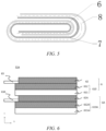
- Fig. 5 is a top view of the electrode assembly 52 shown in Fig. 4 after being wound up. After the electrode assembly is wound up, the positive electrode active material layer of the positive electrode plate 6 is arranged in close contact with the separator 8, and the organic support layer of the positive electrode plate 6 is arranged in close contact with one of the negative electrode active material layers 72 of the negative electrode plate 7.
- the support layer 611 functions as a separator between the positive electrode plate 6 and the negative electrode plate 7.
- the negative electrode plate 7 is separated from the positive electrode plate 6 by the separator 8.
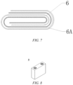
- Fig. 6 is a cross-sectional view of an electrode assembly 52A according to an embodiment of the present application.
- Fig. 7 is a top view of the electrode assembly 52A shown in Fig. 6 after being wound up.
- the electrode assembly 52A differs from the electrode assembly 52 described above in that the positive electrode plate and the negative electrode plate are respectively the electrode plates having the above structure of the present application. That is, the negative electrode plate 6A includes a current collector 610A, an active material layer 62A arranged on one surface of the current collector 610A, and an electrical connection member 63A electrically connected to the current collector 610A.
- the organic support layer 611 of the positive electrode plate 6 is arranged in close contact with the negative electrode active material layer 62A of the negative electrode plate 6A, and an organic support layer 611A of the negative electrode plate 6A is arranged in close contact with the positive electrode active material layer 62 of the positive electrode plate 6.
- the foregoing method is illustrated in the form of wound electrode plates as an example, and it is also applicable to stacked electrode plates.
- a method for manufacturing an electrode assembly including:
- a method for manufacturing an electrode assembly including:
- a secondary battery in one embodiment, includes the composite current collector as described above in the present application or the electrode assembly as described above in the present application.
- the secondary battery further includes an electrolyte.
- active ions are intercalated and de-intercalated back and forth between a positive electrode plate and a negative electrode plate.
- the electrolyte serves to conduct ions between the positive electrode plate and the negative electrode plate.
- the electrolyte serves to conduct ions between the positive electrode plate and the negative electrode plate.
- the type of the electrolyte is not specifically limited in the present application, and can be selected according to actual requirements.
- the electrolyte may be in a liquid state, a gel state or an all-solid state.
- the electrolyte is an electrolyte solution.
- the electrolyte solution includes an electrolyte salt and a solvent.
- the electrolyte salt may be selected from at least one of lithium hexafluorophosphate, lithium tetrafluoroborate, lithium perchlorate, lithium hexafluoroarsenate, lithium bisfluorosulfonimide, lithium bistrifluoromethanesulfonimide, lithium trifluoromethanesulfonate, lithium difluorophosphate, lithium difluorooxalate borate, lithium dioxalate borate, lithium difluorodioxalate phosphate and lithium tetrafluorooxalate phosphate.
- the solvent may be selected from at least one of ethylene carbonate, propylene carbonate, ethyl methyl carbonate, diethyl carbonate, dimethyl carbonate, dipropyl carbonate, methyl propyl carbonate, ethyl propyl carbonate, butylene carbonate, fluoroethylene carbonate, methyl formate, methyl acetate, ethyl acetate, propyl acetate, methyl propionate, ethyl propionate, propyl propionate, methyl butyrate, ethyl butyrate, 1,4-butyrolactone, sulfolane, dimethyl sulfone, ethyl methyl sulfone, and diethyl sulfone.
- the electrolytic solution may optionally include an additive.
- the additive may include a negative electrode film-forming additive and a positive electrode film-forming additive, and may further include an additive that can improve certain performances of the battery, such as an additive that improves the overcharge performance of the battery, or an additive that improves the high temperature or low-temperature performance of the battery.
- the secondary battery may further include a separator provided between the positive electrode plate and the negative electrode plate.
- a separator provided between the positive electrode plate and the negative electrode plate.
- a support layer in the electrode plate of the present application can also function as a separator, in the secondary battery of the present application, when the positive electrode plate and the negative electrode plate are separated by the support layer, no additional separator may be provided.
- the type of the separator is not particularly limited in the present application, and any well known porous-structure separator with good chemical stability and mechanical stability may be selected.
- the material of the separator may be selected from at least one of glass fibers, non-woven fabrics, polyethylene, polypropylene and polyvinylidene fluoride.
- the separator may be a single-layer film and also a multi-layer composite film, and is not limited particularly. When the separator is a multi-layer composite film, the materials in the respective layers may be same or different, which is not limited particularly.
- the positive electrode plate and the negative electrode plate, and the separator provided as required can be made into the electrode assembly by a winding process or a lamination process.
- the secondary battery may include an outer package.
- the outer package can be used to encapsulate the above-mentioned electrode assembly and electrolyte.
- the outer package of the secondary battery may be a hard shell, such as a hard plastic shell, an aluminum shell, or a steel shell.
- the outer package of the secondary battery may also be a soft bag, such as a pouch-type soft bag.
- the material of the soft bag may be plastics, and the examples of plastics may include polypropylene, polybutylene terephthalate, and polybutylene succinate, etc.
- the shape of the secondary battery is not particularly limited in the present application, and may be cylindrical, square or of any other shape.
- Fig. 8 shows a secondary battery 5 of a square structure as an example.
- an outer package may include a housing 51 and a cover plate 53.
- the housing 51 may include a bottom plate and side plates connected to the bottom plate, and the bottom plate and the side plates enclose to form an accommodating cavity.
- the housing 51 has an opening in communication with the accommodating cavity, and the cover plate 53 can cover the opening to close the accommodating cavity.
- the positive electrode plate and the negative electrode plate, and the separator provided as required may be subjected to a winding process or a laminating process to form the electrode assembly 52.
- the electrode assembly 52 is packaged in the accommodating cavity.
- the electrolyte is infiltrated into the electrode assembly 52.
- the number of the electrode assemblies 52 contained in the secondary battery 5 may be one or more, and can be selected by those skilled in the art according to actual requirements.
- the secondary battery may be assembled into a battery module, and the number of the secondary batteries contained in the battery module may be one or more, and the specific number can be selected by those skilled in the art according to the application and capacity of the battery module.
- Fig. 10 shows a battery module 4 as an example.
- a plurality of secondary batteries 5 may be arranged in sequence in the length direction of the battery module 4.
- the secondary batteries may also be arranged in any other manner.
- the plurality of secondary batteries 5 may be fixed by fasteners.
- the battery module 4 may further include a housing with an accommodating space, and a plurality of secondary batteries 5 are accommodated in the accommodating space.
- the above battery module may also be assembled into a battery pack, the number of the battery modules contained in the battery pack may be one or more, and the specific number can be selected by those skilled in the art according to the application and capacity of the battery pack.
- the battery pack 1 may include a battery case and a plurality of battery modules 4 provided in the battery case.
- the battery case includes an upper case body 2 and a lower case body 3.
- the upper case body 2 can cover the lower case body 3 to form a closed space for accommodating the battery modules 4.
- the plurality of battery modules 4 may be arranged in the battery case in any manner.
- the present application further provides a power consuming device including at least one of the secondary battery, the battery module, or the battery pack provided by the present application.
- the secondary battery, the battery module or the battery pack can be used as a power source of the power consuming device or as an energy storage unit of the power consuming device.
- the power consuming device may include a mobile device (e.g., a mobile phone, a laptop computer, etc.), an electric vehicle (e.g., a pure electric vehicle, a hybrid electric vehicle, a plug-in hybrid electric vehicle, an electric bicycle, an electric scooter, an electric golf cart, an electric truck), an electric train, ship, and satellite, an energy storage system, and the like, but is not limited thereto.
- the secondary battery, the battery module or the battery pack can be selected according to the usage requirements thereof.
- Fig. 13 shows a power consuming device as an example.
- the power consuming device may be a pure electric vehicle, a hybrid electric vehicle, a plug-in hybrid electric vehicle or the like.
- a battery pack or a battery module may be used.
- the electrical apparatus may be a mobile phone, a tablet computer, a laptop computer, etc.
- the electrical apparatus is generally required to be thin and light, and may use the secondary battery as a power supply.
- a support layer having a thickness of 5000 nm and an air permeability (greater than or equal to 50 s/100 mL) is selected, and an electrically conductive layer having a thickness is formed on a surface of the support layer by using a photomask with pores and by vacuum evaporation, electroplating and the like.
- the air permeability may be tested by referring to GB/T 36363-2018 .
- the forming conditions of a vacuum evaporation method are as follows: the support layer subjected to a surface cleaning treatment is placed into a vacuum plating chamber, and a high-purity metal wire in the metal evaporation chamber is melted and evaporated at a high temperature of 1300°C to 2000°C. The evaporated metal passes through a cooling system in the vacuum plating chamber, and finally is deposited on the surface of the support layer to form an electrically conductive layer.
- the forming conditions of an electroplating method are as follows:
- a 92 wt% positive electrode active material (if no specific material is specified, NCM333 is used by default), a 5 wt% conductive agent Super-P ("SP" for short), and a 3 wt% PVDF are stirred evenly with a solvent NMP, to prepare a positive electrode active material layer slurry (the composition of the active material layer slurry in some embodiments may vary, and in this case, the specified composition in this embodiment shall prevail).
- Extrusion coating is performed to apply, through partition coating, the positive electrode active material layer slurry on one surface of the composite current collector prepared by the foregoing method;and drying is performed at 85°C to obtain a positive electrode active material layer. Then, the current collector with the respective coating layer is cold-pressed, cut, and then dried under vacuum at 85°C for 4 hours, and a tab is welded to obtain a positive electrode plate.
- the current collector is an Al foil having a thickness of 12 ⁇ m. Similar to the preparation method of the foregoing positive electrode plate, the positive electrode active material layer slurry is directly applied on the surface of the current collector of the Al foil, and then the conventional positive electrode plate is obtained through post-processing.
- a conductive material such as conductive carbon black
- a binder such as PVDF or polyacrylic acid
- an optional active material are dissolved in an appropriate solvent (such as NMP or water), and stirred evenly to form a primer slurry.
- the primer slurry is evenly applied on a surface of the electrically conductive layer of the composite current collector at a coating speed of 20 m/min, and a primer layer is dried at an oven temperature is 70°C to 100°C for 5 min.
- a 92 wt% positive electrode active material, a 5 wt% conductive agent Super-P ("SP" for short), and 3 wt% PVDF are stirred evenly with a solvent NMP, to prepare a positive electrode active material layer slurry.
- Extrusion coating is performed to apply the positive electrode active material layer slurry on the surface of the primer layer through partition coating; and drying is performed at 85°C to obtain a positive electrode active material layer. Then, post-processing is performed to obtain a positive electrode plate with a conductive primer layer.
- a negative electrode active material artificial graphite, a conductive agent Super-P, a thickener CMC, and a binder SBR are added to a deionized water solvent at a mass ratio of 96.5 : 1.0 : 1.0 : 1.5, and mixed evenly to prepare a negative electrode active material layer slurry.
- Extrusion coating is performed to apply the negative electrode active material layer slurry on one surface of the composite current collector prepared by the foregoing methods through partition coating; and drying is performed at 85°C to obtain a negative electrode active material layer.
- the current collector with the respective coating layer is cold-pressed, cut, and then dried under vacuum at 110°C for 4 hours, and a tab is welded to obtain a negative electrode plate.
- the current collector is a Cu foil having a thickness of 8 ⁇ m. Similar to the preparation method of the above negative electrode plate, the negative electrode active material layer slurry is directly applied on the surface of the current collector of the Cu foil, and then the conventional negative electrode plate is obtained through post-processing.
- Negative electrode plate with conductive primer layer
- a conductive material such as conductive carbon black
- a binder such as PVDF or polyacrylic acid
- an optional active material are dissolved in an appropriate solvent (such as NMP or water), and stirred evenly to form a primer slurry.
- the primer slurry is evenly applied on a surface of the electrically conductive layer of the composite current collector at a coating speed of 20 m/min, and a primer layer is dried at an oven temperature is 70°C to 100°C for 5 min.
- a negative electrode active material artificial graphite, a conductive agent Super-P, a thickener CMC, and a binder SBR are added to a deionized water solvent at a mass ratio of 96.5 : 1.0 : 1.0 : 1.5, and mixed evenly to prepare a negative electrode active material layer slurry.
- Extrusion coating is performed to apply the negative electrode active material layer slurry on the primer layer of the current collector by partition coating; and drying is performed at 85°C to obtain a negative electrode active material layer.
- post-processing is performed to obtain a negative electrode plate having a conductive primer layer in an extension area.
- a positive electrode plate having a compacted density of 3.4 g/cm 3
- a negative electrode plate having a compacted density of 1.6 g/cm 3
- a PP/PE/PP separator which may be two separators, one separator or no separator as required
- an electrolyte solution having a volume ratio of EC to EMC of 3 : 7, and a concentration of LiPF6 of 1 mol/L
- a lithium-ion secondary battery hereinafter referred to as the battery for short
- a battery is discharged to 3.0V at 25 ⁇ 5 °Cwith a constant current of 1.0 CmA, and is fully charged and subjected to standing for 2 hours, followed by visual inspection on the battery, measurement of size, open-circuit voltage and internal resistance of the battery, and after the test, cycling at 1.0 CmA is performed for three times (discharging; fully charging and discharging; fully charging and discharging; 50% charging or fully charging), and the discharge capacity and the midpoint voltage in the 3rd week are then tested.
- the battery After the battery is fully charged at an ambient temperature of 25 ⁇ 5°C, it is subj ected to standing for 10 min, discharged to 3.0V at a current of 10.0 CmA or nominal rate, and subjected to standing for 10 min, and cycling is performed by repeating the above steps until the battery discharge capacity is not greater than 80% of the discharge capacity in the 3rd week twice.
- a large constant DC current (currently, a large current of 40A-80A is generally used) is forcedly introduced by a test apparatus to the battery for a short period of time (generally 2-3 seconds), the voltage across the battery is then measured, and the current internal resistance of the battery is calculated according to the formula.
- composite current collectors 1 to 9 and Examples 1 to 7 and Comparative Examples 1 and 2 of secondary batteries are prepared substantially based on "1. Preparation of composite current collector", "2. Preparation of electrode plate” and "3. Preparation of battery” described above, and are tested.
- composite current collectors 10 to 20 and Examples 8 to 18 and Comparative Examples 3 of secondary batteries are prepared substantially based on "1. Preparation of composite current collector", "2. Preparation of electrode plate” and "3. Preparation of battery” described above, and are tested.
- Example 3, 19, and Comparative Example 3 of secondary batteries are prepared substantially based on "1, Preparation of composite current collector”, "2, Preparation of electrode plate”, and “3, Preparation of battery” described above, and are subjected to volumetric energy density tests.
- Example 3, 19, and Comparative Example 3 of secondary batteries are prepared substantially based on "1, Preparation of composite current collector", "2, Preparation of electrode plate”, and “3, Preparation of battery” described above, and are subjected to volumetric energy density tests.
- Example 10 Composite current collector 12, with one side coated Conventional electrode plate, with both sides coated 1.1 m ⁇
- Example 20 Composite current collector 12, having primer layer, with one side coated Conventional electrode plate, with both sides coated 0.95 m ⁇
- Example 21 Composite current collector 12, having primer layer, with one side coated Composite current collector 12, having primer layer, with one side coated Composite current collector 12, having primer layer, with one side coated 1.05 m ⁇
- Example 10 shows that secondary batteries having primer layers in Examples 20 and 21 have a lower internal resistance.
Landscapes
- Chemical & Material Sciences (AREA)
- Chemical Kinetics & Catalysis (AREA)
- Electrochemistry (AREA)
- General Chemical & Material Sciences (AREA)
- Engineering & Computer Science (AREA)
- Materials Engineering (AREA)
- Manufacturing & Machinery (AREA)
- Composite Materials (AREA)
- Cell Electrode Carriers And Collectors (AREA)
- Secondary Cells (AREA)
- Cell Separators (AREA)
- Battery Electrode And Active Subsutance (AREA)
Abstract
The present application provides a composite current collector, including: an organic support layer having an air permeability greater than or equal to 50 s/100 mL; and an electrically conductive layer arranged on one surface of the organic support layer. In this way, the organic support layer can also be used as a separator, thereby increasing the volumetric energy density of a secondary battery using the composite current collector.
Description
- The present application relates to the field of electrochemistry, and in particular to, a composite current collector and a manufacturing method therefor, a secondary battery having the same, and a power consuming device.
- In recent years, with the increasing application range of lithium-ion batteries, lithium-ion batteries are widely used in energy storage power systems such as hydroelectric, thermal, wind and solar power stations, as well as electric tools, electric bicycles, electric motorcycles, electric vehicles, military equipment, aerospace and other fields. Due to the great development of lithium-ion batteries, higher requirements have also been placed on the lithium-ion secondary batteries in terms of energy density, cycle performance, safety performance, etc.
- An electrode plate of the prior art includes: a metal current collector and active material layers formed on two surfaces of the current collector.Moreover, electrode plates of different polarities are separated from each other by separators. Such an electrode plate structure requires winding up or stacking two layers of separators during manufacturing, and its manufacturing process is complicated. In addition, a secondary battery using this electrode plate structure has a long ion channel, which affects charge and discharge characteristics.
- The present application has been made in view of the above problems, and an objective thereof is to provide a composite current collector and a manufacturing method therefor, a secondary battery having the same, and a power consuming device. With the composite current collector, a separator provided between electrode plates can be omitted, the manufacturing process can be simplified, the ion channel can be shortened, and the charge and discharge characteristics can be improved. In addition, since a space for providing the separator is saved, more active material can be coated per unit volume, thereby increasing the energy density.
- In order to achieve the above objective, a first aspect of the present application provides a composite current collector, including: an organic support layer having an air permeability greater than or equal to 50 s/100mL; and an electrically conductive layer arranged on one surface of the organic support layer.
- An organic layer having an air permeability greater than or equal to 50 s/100mL is used as a support layer of the composite current collector, and the support layer can be used as a separator, so that a separator provided between electrode plates can be omitted, the manufacturing process can be simplified, the ion channel can be shortened, and the charge and discharge characteristics can be improved. In addition, since a space for providing the separator is saved, more active material can be coated per unit volume, thereby increasing the energy density.
- In some embodiments, the organic support layer has an air permeability of 50 s/100 mL to 2000 s/100 mL, and optionally, 100 s/100 mL to 500 s/100 mL. The air permeability of the organic support layer is controlled within the above-mentioned range, so that the ion permeability can be ensured, and an electrolyte solution can have a good infiltration performance, allowing lithium ions of the electrolyte solution to pass through smoothly. If the air permeability is too high, pores of the separator are equivalent to closed pores, and lithium ions of the electrolyte solution cannot pass through the separator, so that high ion permeability cannot be achieved. If the air permeability is too low, pores of the separator are equivalent to through pores, and large-particle ions of other materials may also pass through, so that the separator is ineffective. Thus, by setting the air permeability reasonably, the charge and discharge characteristics of the secondary battery can be further improved.
- In some embodiments, the electrically conductive layer has pores, and the electrically conductive layer has a porosity of 10% to 95%, and optionally, 10% to 50%. Since the porosity of the electrically conductive layer is controlled within the above-mentioned range, the required ion permeability can be met, further improving the charge and discharge characteristics of the secondary battery. By keeping the porosity in an appropriate range, insufficient ion permeability can be avoided, and a circumstance where ions are immersed into the electrically conductive layer while surplus ions fail to penetrate due to the lack of space in the organic support layer can be avoided. In addition, an upper limit of a fiber pore permeability of the organic support layer is positively correlated with an upper limit of the porosity of the electrically conductive layer, which can ensure ion permeability.
- In some embodiments, the organic support layer is a polyethylene film, a polypropylene film, a polyvinylidene chloride film or a multi-layer composite film thereof. The organic support layer made of the above-mentioned material can reliably form a support layer with a high ion permeability.
- In some embodiments, the electrically conductive layer has a thickness of 200 nm to 3000 nm, and optionally, 500 nm to 1500 nm. Since the thickness of the electrically conductive layer is within the above-mentioned range, it is conductive to improving the volumetric energy density of the secondary battery, and under an abnormal condition such as nail penetration of the secondary battery, burr generated by the electrically conductive layer is reduced greatly, short-circuit resistance of the secondary battery is increased, and short-circuit current and short-circuit heat generation are reduced, thereby improving the safety performance of the secondary battery; moreover, it is conducive to making the composite current collector have a good electrical conductivity and current collection performance, and less prone to breakage during processing and use of the composite current collector, so that the composite current collector has a good mechanical stability and a long service life.
- In some embodiments, the electrically conductive layer includes a pore-making transition layer, a thickening layer, a functional layer, and a protective layer that are stacked in sequence from the organic support layer. In this way, the ion channel can be formed on the electrically conductive layer well and the thickness of the electrically conductive layer can be adjusted easily. In addition, the protective layer can prevent the electrically conductive layer from chemical corrosion, mechanical damage or other damages, to ensure that the composite current collector has a high working stability and a long service life. In addition, the protective layer can also enhance the mechanical strength of the composite current collector.
- In some embodiments, the pore-making transition layer, the thickening layer, and the functional layer each are made of one or more of aluminum, an aluminum alloy, copper, a copper alloy, nickel, a nickel alloy, titanium, a titanium alloy, iron, an iron alloy, silver and a silver alloy, and the protective layer includes one or more of metal, metal oxide, and conductive carbon, and preferably includes one or more of nickel, chromium, a nickel-based alloy, a copper-based alloy, aluminum oxide, cobalt oxide, chromium oxide, nickel oxide, graphite, superconducting carbon, acetylene black, carbon black, Ketjen black, a carbon dot, a carbon nanotube, graphene, and a carbon nanofiber. In this way, the protective layer can play a protective role against chemical corrosion and mechanical damage to the electrically conductive layer, and can also improve an interface between the composite current collector and the active material layer, increase a bonding force between the composite current collector and the positive electrode active material layer, and improve the performance of the secondary battery.
- In some embodiments, the pore-making transition layer has a thickness of 2 nm to 100 nm, and optionally, 10 nm to 50 nm; the thickening layer has a thickness of 5 nm to 300 nm, and optionally, 20 nm to 100 nm; and the functional layer has a thickness of 500 nm to 5000 nm, and optionally, 500 nm to 2000 nm. In this way, the ion permeability, the electrical conductivity and the mechanical stability of the composite current collector can be balanced.
- A primer layer is further provided between the active material layer and the electrically conductive layer, the primer layer including a binder and a conductive agent. The primer layer can improve an interface of the composite current collector and overcome shortcomings such as poor electrical conductivity and current flow capacity of the composite current collector and the electrically conductive layer of the composite current collector being susceptible to damage, and can improve the electron transport efficiency, and reduce the resistance between the current collector and the electrode active material layer by effectively mending the surface of the current collector and constructing a conductive network between the current collector, the conductive primer layer and the active material, thereby effectively reducing the internal direct-current internal resistance in the secondary battery, improving the power performance of the secondary battery, and ensuring that a cell is less prone to large polarization, lithium precipitation and other phenomena during long-term cycling, that is, the long-term reliability of the secondary battery is effectively improved.
- A second aspect of the present application provides an electrode assembly, including a first electrode plate and a second electrode plate, wherein one of the first electrode plate and the second electrode plate includes the composite current collector in the first aspect, an active material layer is provided on the electrically conductive layer of the composite current collector, and the organic support layer of the one of the first electrode plate and the second electrode plate is arranged in close contact with an active material layer of the other one of the first electrode plate and the second electrode plate. In this way, the electrode plate including the composite current collector in the first aspect of the present application may be used with a common electrode plate with the opposite polarity, thereby omitting the use of a separator layer.
- A third aspect of the present application provides an electrode assembly, including a first electrode plate and a second electrode plate, wherein the first electrode plate and the second electrode plate each include the composite current collector in the first aspect of the present application, an active material layer is provided on the electrically conductive layer of the composite current collector, the organic support layer of the first electrode plate is arranged in close contact with the active material layer of the second electrode plate, and the organic support layer of the second electrode plate is arranged in close contact with the active material layer of the first electrode plate. In this way, with the electrode plates that include the composite current collector in the first aspect of the present application and have different polarities, the second battery can be formed without a separator.
- A fourth aspect of the present application provides a method for manufacturing the composite current collector according to the first aspect of the present application, the method including the following steps (1) to (3):
- step (1): forming an organic support layer having an air permeability greater than or equal to 50 s/100 mL;
- step (2): forming a pore-making transition layer on one surface of the organic support layer by vapor deposition and by using a photomask with pores; and
- step (3): forming an electrically conductive metal layer on the pore-making transition layer by electroplating.
- By the foregoing method, pores can be formed in the electrically conductive metal layer by using a photomask, so that high ion permeability can be achieved, further improving the charge and discharge characteristics of the secondary battery. In addition, the pore-making transition layer serves as a substrate for an electroplated layer, so that an electroplated layer with pores can be formed easily, and the thickness of the electrically conductive metal layer can be adjusted easily by electroplating.
- In some embodiments, the method further includes:
step (4): forming a protective layer on the electrically conductive metal layer. - In this way, the protective layer can prevent the electrically conductive layer from chemical corrosion, mechanical damage or other damages, to ensure that the composite current collector has a high working stability and a long service life. In addition, the protective layer can also enhance the mechanical strength of the composite current collector.
- In some embodiments, in step (2), a pore size and a porosity of the pore-making transition layer are adjusted with a pore size and a pore density of the photomask. In this way, ion permeability and the electrical conductivity of the composite current collector can be balanced.
- In some embodiments, in step (2), an electrically conductive material is evaporated in a vacuum plating chamber at a temperature of 1300°C to 2000°C, and is then cooled and deposited on the organic support layer to form the pore-making transition layer. In this way, a bonding force between the electrically conductive metal layer and the organic support layer can be increased, and the organic support layer is effective in supporting the electrically conductive metal layer.
- In some embodiments, in step (4), the protective layer is formed on the electrically conductive metal layer by at least one of a vapor deposition method, an in-situ formation method or a coating method. In this way, a relatively high bonding force is provided between the electrically conductive layer and the protective layer, so that the protective layer better protects the composite current collector, and a higher operating performance of the composite current collector is ensured.
- A fifth aspect of the present application provides a method for manufacturing a battery assembly, the method including:
- preparing a first electrode plate, the first electrode plate including a first composite current collector which is a composite current collector in the first aspect of the present application, an active material layer being provided on the electrically conductive layer of the composite current collector;
- preparing a second electrode plate, the second electrode plate including a second current collector and active material layers provided on two surfaces of the second current collector;
- preparing a separator; and
- stacking the first electrode plate, the second electrode plate and the separator in sequence in such a way that the organic support layer of the first composite current collector of the first electrode plate is in contact with one of the active material layers of the second electrode plate and the other active material layer of the second electrode plate is in contact with the separator, to obtain a stacked structure, and winding up the stacked structure.
- In this way, the use of a separator layer for manufacturing the electrode assembly can be omitted.
- A sixth aspect of the present application provides a method for manufacturing a battery assembly, the method including:
- preparing a first electrode plate and a second electrode plate, the first electrode plate including a first composite current collector and the second electrode plate including a second composite current collector, the first composite current collector and the second composite current collector each being a composite current collector in the first aspect of the present application, an active material layer being provided on the electrically conductive layer of the composite current collector; and
- winding up the first electrode plate and the second electrode plate in such a way that the organic support layer of the first composite current collector of the first electrode plate is in contact with the active material layer of the second electrode plate and the organic support layer of the second composite current collector of the second electrode plate is in contact with the active material layer of the first electrode plate.
- In this way, the electrode assembly can be manufactured without a separator.
- A seventh aspect of the present application provides a secondary battery including at least one of an electrode assembly according to the second and third aspects of the present application and an electrode assembly manufactured by the manufacturing method according to the fifth and sixth aspects of the present application.
- An eighth aspect of the present application provides a power consuming device including a secondary battery according to the seventh aspect of the present application.
- According to the present application, the cycling performance, the rate performance and the low internal resistance of the secondary battery can be balanced.
-
-
Fig. 1 is a schematic cross-sectional view of a composite current collector according to an embodiment of the present application. -
Fig. 2 is a schematic cross-sectional view of a composite current collector according to an embodiment of the present application. -
Fig. 3 is a schematic cross-sectional view of a composite current collector according to an embodiment of the present application. -
Fig. 4 is a cross-sectional view of an electrode assembly according to an embodiment of the present application. -
Fig. 5 is a top view of the electrode assembly shown inFig. 4 after being wound up. -
Fig. 6 is a cross-sectional view of an electrode assembly according to an embodiment of the present application. -
Fig. 7 is a top view of the electrode assembly shown inFig. 6 after being wound up. -
Fig. 8 is a schematic view of a secondary battery according to an embodiment of the present application. -
Fig. 9 is an exploded view of a secondary battery according to an embodiment of the present application as shown inFig. 8 . -
Fig. 10 is a schematic view of a battery module according to an embodiment of the present application. -
Fig. 11 is a schematic view of a battery pack according to an embodiment of the present application. -
Fig. 12 is an exploded view of a battery pack according to an embodiment of the present application as shown inFig. 11 . -
Fig. 13 is a schematic view of a power consuming device using a secondary battery as a power source according to an embodiment of the present application. - 1 battery pack; 2 upper case body; 3 lower case body; 4 battery module; 5 secondary battery; 51 housing; 52, 52A electrode assembly; 53 top cover assembly; 610, 610A composite current collector; 611, 611A organic support layer; 612, 612A electrically conductive layer; 62, 62A active material layer; 6121 pore-making transition layer; 6122 thickening layer; 6123 functional layer; 6124 protective layer; 63, 63A electrical connection member; 64 primer layer; 6, 6A, 7 electrode plate; 71 current collector; 72 active material layer; 73 electrical connection member; 8 separator.
- Hereinafter, embodiments of a positive electrode material and a manufacturing method therefor, a secondary battery, a battery module, a battery pack, and an electrical device of the present application are specifically disclosed in the detailed description with reference to the accompanying drawings as appropriate. However, unnecessary detailed illustrations may be omitted in some instances. For example, there are situations where detailed description of well known items and repeated description of actually identical structures are omitted. This is to prevent the following description from being unnecessarily verbose, and facilitates understanding by those skilled in the art. Moreover, the accompanying drawings and the descriptions below are provided for enabling those skilled in the art to fully understand the present application, rather than limiting the subject matter disclosed in claims.
- "Ranges" disclosed in the present application are defined in the form of lower and upper limits, and a given range is defined by selection of a lower limit and an upper limit, the selected lower and upper limits defining the boundaries of the particular range. Ranges defined in this manner may be inclusive or exclusive, and may be arbitrarily combined, that is, any lower limit may be combined with any upper limit to form a range. For example, if the ranges of 60 to 120 and 80 to 110 are listed for a particular parameter, it should be understood that the ranges of 60 to 110 and 80 to 120 are also contemplated. Additionally, if
minimum range values maximum range values 3, 4, and 5 are listed, the following ranges are all contemplated: 1 to 3, 1 to 4, 1 to 5, 2 to 3, 2 to 4, and 2 to 5. In the present application, unless stated otherwise, the numerical range "a to b" denotes an abbreviated representation of any combination of real numbers between a and b, where both a and b are real numbers. For example, the numerical range "0 to 5" means that all real numbers between "0 to 5" have been listed herein, and "0 to 5" is just an abbreviated representation of combinations of these numerical values. In addition, when a parameter is expressed as an integer of≥ 2, it is equivalent to disclosing that the parameter is, for example, an integer of 2, 3, 4, 5, 6, 7, 8, 9, 10, 11, 12, and the like. - All the embodiments and optional embodiments of the present application can be combined with one another to form new technical solutions, unless otherwise stated.
- All technical features and optional technical features of the present application can be combined with one another to form a new technical solution, unless otherwise stated.
- The terms "comprise" and "include" mentioned in the present application are open-ended or closed-ended, unless otherwise stated. For example, the terms "comprising" and "including" may mean that other components not listed may also be comprised or included, or only the listed components may be comprised or included.
- In the present application, the term "or" is inclusive unless otherwise specified. For example, the phrase "A or B" means "A, B, or both A and B." More specifically, a condition "A or B" is satisfied by any one of the following: A is true (or present) and B is false (or not present); A is false (or not present) and B is true (or present); or both A and B are true (or present).
- In an embodiment of the present application, a composite current collector is provided, including: an organic support layer having an air permeability greater than or equal to 50 s/100 mL; and an electrically conductive layer arranged on one surface of the organic support layer.
- The applicant has found that an organic layer having an air permeability greater than or equal to 50 s/100 mL is used as a support layer of the composite current collector, and the support layer can be used as a separator, so that a separator provided between electrode plates can be omitted, the manufacturing process can be simplified, the ion channel can be shortened, and the charge and discharge characteristics can be improved. In addition, since a space for providing the separator is saved, more active material can be coated per unit volume, thereby increasing the energy density.
- In addition, the composite current collector, the secondary battery, and the power consuming device of the present application will be described below by appropriately referring to the accompanying drawings.
-
Fig. 1 is a schematic cross-sectional view of a composite current collector according to an embodiment of the present application. As shown inFig. 1 , the compositecurrent collector 610 includes: anorganic support layer 611 having an air permeability greater than or equal to 50 s/100 mL; and an electricallyconductive layer 612 arranged on one surface of theorganic support layer 611, with anactive material layer 62 being provided on the electricallyconductive layer 612. - In some embodiments, optionally, the
organic support layer 611 has an air permeability of 50 s/100 mL to 2000 s/100 mL, and optionally, 100 s/100 mL to 500 s/100 mL. The air permeability of the organic support layer is controlled within the above-mentioned range, so that the ion permeability can be ensured, and an electrolyte solution can have a good infiltration performance, allowing lithium ions of the electrolyte solution to pass through smoothly. If the air permeability is too high, pores of the separator are equivalent to closed pores, and lithium ions of the electrolyte solution cannot pass through the separator, so that high ion permeability cannot be achieved. If the air permeability is too low, pores of the separator are equivalent to through pores, and large-particle ions of other materials may also pass through, so that the separator is ineffective. Thus, by setting the air permeability reasonably, the charge and discharge characteristics of the secondary battery can be further improved. - In some embodiments, optionally, the electrically
conductive layer 612 has pores, and the electricallyconductive layer 612 has a porosity of 10% to 95%, and optionally, 10% to 50%. Since the porosity of the electricallyconductive layer 612 is controlled within the above-mentioned range, the required ion permeability can be met, further improving the charge and discharge characteristics of the secondary battery. By keeping the porosity in an appropriate range, insufficient ion permeability can be avoided, and a circumstance where ions are immersed into the electrically conductive layer while surplus ions fail to penetrate due to the lack of space in theorganic support layer 611 can be avoided. In addition, an upper limit of a fiber pore permeability of theorganic support layer 611 is positively correlated with an upper limit of the porosity of the electrically conductive layer, which can ensure ion permeability. - In some embodiments, in order to increase an infiltration rate of the electrolyte solution and to allow rapid permeation of ions, an average pore size of the electrically
conductive layer 612 may be set to be from 100 nm to 1000 nm. - In some embodiments, optionally, the
organic support layer 611 is a polyethylene film, a polypropylene film, a polyvinylidene chloride film or a multi-layer composite film thereof. The organic support layer made of the above-mentioned material can reliably form a support layer with a high ion permeability. - In some embodiments, optionally, the
organic support layer 611 has a thickness of, for example, 1000 nm to 8000 nm. In this way, a sufficient supporting strength can be provided. - In some embodiments, optionally, when the air permeability is 50 s/100 mL to 2000 s/100 mL, the organic support layer may be made of one or more of polyamide (PA), polyimide (PI), polyester, polyolefin, polyyne, siloxane polymer, polyether, polyalcohol, polysulfone, polysaccharide polymer, amino acid polymer, polysulfur nitride, aromatic ring polymer, aromatic heterocyclic polymer, epoxy resin, phenolic resin, derivatives thereof, crosslinked products thereof, and copolymers thereof. Further, the organic support layer is made of, for example, one or more of polycaprolactam (commonly known as nylon 6), polyhexamethylene adipamide (commonly known as nylon 66), polyp-phenylene terephthamide (PPTA), poly(isophthaloyl metaphenylene diamine) (PMIA), polyethylene terephthalate (PET), polybutylene terephthalate (PBT), polyethylene naphthalate (PEN), polycarbonate (PC), polyethylene (PE), polypropylene (PP), polypropylene ethylene (PPE), polyvinyl alcohol (PVA), polystyrene (PS), polyvinyl chloride (PVC), polyvinylidene fluoride (PVDF), polytetrafluoroethylene (PTEE), polystyrene sulfonate (PSS), polyacetylene, polypyrrole (PPy), polyaniline (PAN), polythiophene (PT), polypyridine (PPY), silicone rubber, polyformaldehyde (POM), polyphenylene, polyphenyl ether (PPO), polyphenylene sulfide (PPS), polyethylene glycol (PEG), acrylonitrile-butadiene-styrene copolymer (ABS), cellulose, starch, protein, derivatives thereof, crosslinked products thereof, and copolymers thereof.
- In some embodiments, optionally, the electrically
conductive layer 612 has a thickness of 200 nm to 3000 nm, and optionally, 500 nm to 1500 nm. Since the thickness of the electrically conductive layer is within the above-mentioned range, it is conductive to improving the volumetric energy density of the secondary battery, and under an abnormal condition such as nail penetration of the secondary battery, burr generated by the electrically conductive layer is reduced greatly, short-circuit resistance of the secondary battery is increased, and short-circuit current and short-circuit heat generation are reduced, thereby improving the safety performance of the secondary battery; moreover, it is conducive to making the composite current collector have a good electrical conductivity and current collection performance, and less prone to breakage during processing and use of the composite current collector, so that the composite current collector has a good mechanical stability and a long service life. - In some embodiments, optionally, as shown in
Fig. 2 , the electricallyconductive layer 612 includes a pore-makingtransition layer 6121, athickening layer 6122, afunctional layer 6123, and aprotective layer 6124 that are stacked in sequence from theorganic support layer 611. In this way, the ion channel can be formed on the electricallyconductive layer 612 well and the thickness of the electricallyconductive layer 612 can be adjusted easily. In addition, theprotective layer 6124 can prevent the electricallyconductive layer 612 from chemical corrosion, mechanical damage or other damages, to ensure that the compositecurrent collector 610 has a high working stability and a long service life. In addition, theprotective layer 6124 can also enhance the mechanical strength of the compositecurrent collector 610. - In some embodiments, optionally, the pore-making
transition layer 6121, the thickeninglayer 6122, and thefunctional layer 6123 each are made of one or more of aluminum, an aluminum alloy, copper, a copper alloy, nickel, a nickel alloy, titanium, a titanium alloy, iron, an iron alloy, silver and a silver alloy, and theprotective layer 6124 includes one or more of metal, metal oxide, and conductive carbon, and preferably includes one or more of nickel, chromium, a nickel-based alloy, a copper-based alloy, aluminum oxide, cobalt oxide, chromium oxide, nickel oxide, graphite, superconducting carbon, acetylene black, carbon black, Ketjen black, a carbon dot, a carbon nanotube, graphene, and a carbon nanofiber. In this way, theprotective layer 6124 can play a protective role against chemical corrosion and mechanical damage to the electrically conductive layer, and can also improve an interface between the composite current collector and the active material layer, increase a bonding force between the composite current collector and the positive electrode active material layer, and improve the performance of the secondary battery. - In some embodiments, optionally, the pore-making
transition layer 6121 has a thickness of 2 nm to 100 nm, and optionally, 10 nm to 50 nm; thethickening layer 6122 has a thickness of 5 nm to 300 nm, and optionally, 20 nm to 100 nm; and thefunctional layer 6123 has a thickness of 500 nm to 5000 nm, and optionally, 500 nm to 2000 nm. In this way, the ion permeability, the electrical conductivity and the mechanical stability of the compositecurrent collector 610 can be balanced. - In some embodiments, optionally, the
protective layer 6124 has a thickness of 20 nm to 100 nm. In this way, oxidation of the electrically conductive layer can be avoided. - In some embodiments, optionally, as shown in
Fig. 3 , aprimer layer 64 is further provided between theactive material layer 62 and the electricallyconductive layer 612, theprimer layer 64 including a binder and a conductive agent. Theprimer layer 64 can improve an interface of the compositecurrent collector 610 and overcome shortcomings such as poor electrical conductivity and current flow capacity of the composite current collector and the electrically conductive layer of the composite current collector being susceptible to damage, and can improve the electron transport efficiency, and reduce the resistance between the current collector and the electrode active material layer by effectively mending the surface of the current collector and constructing a conductive network between the current collector, the conductive primer layer and the active material, thereby effectively reducing the internal direct-current internal resistance in the secondary battery, improving the power performance of the secondary battery, and ensuring that a cell is less prone to large polarization, lithium precipitation and other phenomena during long-term cycling, that is, the long-term reliability of the secondary battery is effectively improved. - Apparently, the composite current collector in the present application can be used for either positive or negative electrode plates. When it is used for the positive electrode plate, correspondingly, the composite current collector and the active material layer are a positive electrode current collector and a positive electrode active material layer, respectively. When it is used for a negative electrode plate, correspondingly, the composite current collector and the active material layer are a negative electrode current collector and a negative electrode active material layer, respectively.
- When the composite
current collector 610 of the present application is a positive electrode current collector, the positive electrode plate includes a positive electrode composite current collector and a positive electrode active material layer arranged on one surface of the positive electrode current collector. The positive electrode active material layer includes a positive electrode active material. - In some embodiments, the positive electrode active material may be a positive electrode active material known in the art for batteries. As an example, the positive electrode active material may include at least one of the following materials: lithium-containing phosphates of an olivine structure, lithium transition metal oxides and their respective modified compounds. However, the present application is not limited to these materials, and other conventional materials that can be used as positive electrode active materials for batteries may also be used. These positive electrode active materials may be used alone or in combination of two or more. Examples of lithium transition metal oxides may include, but are not limited to, at least one of lithium cobalt oxide (e.g. LiCoO2), lithium nickel oxide (e.g. LiNiO2), lithium manganese oxide (e.g. LiMnO2, and LiMn2O4), lithium nickel cobalt oxide, lithium manganese cobalt oxide, lithium nickel manganese oxide, lithium nickel cobalt manganese oxide (e.g. LiNi1/3Co1/3Mn1/3O2 (also abbreviated as NCM333), LiNi0.5Co0.2Mn0.3O2 (also abbreviated as NCM523), LiNi0.5Co0.25Mn0.25O2 (also abbreviated as NCM211), LiNi0.6Co0.2Mn0.2O2 (also abbreviated as NCM622), LiNi0.8Co0.1Mn0.1O2 (also abbreviated as NCM811), lithium nickel cobalt aluminum oxide (e.g. LiNi0.85Co0.15Al0.05O2), modified compounds thereof, and the like. Examples of lithium-containing phosphates of olivine structure may include, but are not limited to, at least one of lithium iron phosphate (e.g. LiFePO4 (also abbreviated as LFP)), lithium iron phosphate and carbon composites, lithium manganese phosphate (e.g. LiMnPO4), lithium manganese phosphate and carbon composites, lithium iron manganese phosphate, and lithium iron manganese phosphate and carbon composites.
- In some embodiments, the positive electrode active material layer also optionally includes a binder. As an example, the binder may include at least one of polyvinylidene fluoride (PVDF), polytetrafluoroethylene (PTFE), vinylidene fluoride-tetrafluoroethylene-propylene terpolymer, vinylidene fluoride-hexafluoropropylene-tetrafluoroethylene terpolymer, tetrafluoroethylenehexafluoropropylene copolymer, and fluorine-containing acrylate resin.
- In some embodiments, the positive electrode active material layer also optionally includes a conductive agent. As an example, the conductive agent may include at least one of superconducting carbon, acetylene black, carbon black, Ketjen black, carbon dots, carbon nanotubes, graphene, and carbon nanofibers.
- In some embodiments, the positive electrode plate may be prepared as follows: dispersing the above-described components for preparing the positive electrode plate, such as a positive electrode active material, a conductive agent, a binder and any other components, in a solvent (e.g., N-methylpyrrolidone) to form a positive slurry; and coating the positive electrode composite current collector with the positive electrode slurry, followed by the procedures such as drying and cold pressing, so as to obtain the positive electrode plate.
- When the composite
current collector 610 of the present application is a negative electrode current collector, the negative electrode plate includes a negative electrode composite current collector and a negative electrode active material layer arranged on one surface of the negative electrode current collector. The negative electrode active material layer includes a negative electrode active material. - In some embodiments, the negative electrode active material may be a negative electrode active material known in the art for batteries. As an example, the negative electrode active material may include at least one of the following materials: artificial graphite, natural graphite, soft carbon, hard carbon, a silicon-based material, a tin-based material and lithium titanate, etc. The silicon-based material may be selected from at least one of elemental silicon, silicon oxides, silicon carbon composites, silicon nitrogen composites and silicon alloys. The tin-based material may be selected from at least one of elemental tin, tin oxides, and tin alloys. However, the present application is not limited to these materials, and other conventional materials that can be used as negative electrode active materials for batteries can also be used. These negative electrode active materials may be used alone or in combination of two or more.
- In some embodiments, the negative electrode active material layer also optionally includes a binder. The binder may be selected from at least one of a butadiene styrene rubber (SBR), polyacrylic acid (PAA), sodium polyacrylate (PAAS), polyacrylamide (PAM), polyvinyl alcohol (PVA), sodium alginate (SA), polymethacrylic acid (PMAA) and carboxymethyl chitosan (CMCS).
- In some embodiments, the negative electrode active material layer also optionally includes a conductive agent. The conductive agent may be selected from at least one of superconductive carbon, acetylene black, carbon black, ketjenblack, carbon dots, carbon nanotubes, graphene, and carbon nanofibers.
- In some embodiments, the negative electrode active material layer also optionally includes other auxiliary agents, e.g., a thickener (e.g. sodium carboxymethyl cellulose (CMC-Na)).
- In some embodiments, the negative electrode plate may be prepared as follows: dispersing the above-mentioned components for preparing the negative electrode plate, such as negative electrode active material, conductive agent, binder and any other components, in a solvent (e.g. deionized water) to form a negative electrode slurry; and coating a negative electrode composite current collector with the negative electrode slurry, followed by procedures such as drying and cold pressing, so as to obtain the negative electrode plate.
- In another embodiment of the present application, a method for manufacturing a composite current collector is provided, the method including the following steps (1) to (3):
- step (1): forming an organic support layer having an air permeability greater than or equal to 50 s/100 mL;
- step (2): forming a pore-making transition layer on one surface of the organic support layer by vapor deposition and by using a photomask with pores; and
- step (3): forming an electrically conductive metal layer on the pore-making transition layer by electroplating.
- By the foregoing method, pores can be formed in the electrically conductive metal layer by using a photomask, so that high ion permeability can be achieved, further improving the charge and discharge characteristics of the secondary battery. In addition, the pore-making transition layer serves as a substrate for an electroplated layer, so that an electroplated layer with pores can be formed easily, and the thickness of the electrically conductive metal layer can be adjusted easily by electroplating.
- In some embodiments, the method further includes:
step (4): forming a protective layer on the electrically conductive metal layer. - In this way, the protective layer can prevent the electrically conductive layer from chemical corrosion, mechanical damage or other damages, to ensure that the composite current collector has a high working stability and a long service life. In addition, the protective layer can also enhance the mechanical strength of the composite current collector.
- In some embodiments, in step (2), a pore size and a porosity of the pore-making transition layer are adjusted with a pore size and a pore density of the photomask. In this way, ion permeability and the electrical conductivity of the composite current collector can be balanced.
- In some embodiments, in step (2), an electrically conductive material is evaporated in a vacuum plating chamber at a temperature of 13 00°C to 2000°C, and is then cooled and deposited on the organic support layer to form the pore-making transition layer. In this way, a bonding force between the electrically conductive metal layer and the organic support layer can be increased, and the support layer is effective in supporting the electrically conductive metal layer.
- In some embodiments, in step (4), the protective layer is formed on the electrically conductive metal layer by at least one of a vapor deposition method, an in-situ formation method or a coating method. In this way, a relatively high bonding force is provided between the electrically conductive layer and the protective layer, so that the protective layer better protects the composite current collector, and a higher operating performance of the composite current collector is ensured.
- In some embodiments, a thickening layer and a functional layer may be formed separately by electroplating twice in step (3). In this way, electrically conductive metal layers of different thicknesses can be easily formed.
- In an embodiment of the present application, an electrode assembly is provided. The
electrode assembly 52 includes a positive electrode plate (first electrode plate) 6, a negative electrode plate (second electrode plate) 7, and aseparator 8 which prevents short-circuiting of positive and negative electrodes when the electrode assembly is made by a winding process and which also allows ions to pass through. In this specification, the positive electrode plate is referred to as the first electrode plate and the negative electrode plate is referred to as the second electrode plate, and vice versa. - In some embodiments, the positive electrode plate among the positive and negative electrode plates is the
electrode plate 6 having the above-mentioned structure of the present application. The negative electrode plate among the positive and negative electrode plates is theelectrode plate 7 having a conventional structure, and vice versa. - As shown in
Fig. 4 , thepositive electrode plate 6 includes the compositecurrent collector 610, theactive material layer 62 arranged on one surface of the compositecurrent collector 610, and anelectrical connection member 63 electrically connected to the electricallyconductive layer 612 of the compositecurrent collector 610. - The
negative electrode plate 7 includes a negative electrodecurrent collector 71, negative electrode active material layers 72 formed on two surfaces of the negative electrodecurrent collector 71, and anelectrical connection member 73 electrically connected to the negative electrodecurrent collector 71. Theorganic support layer 611 of thepositive electrode plate 6 is arranged in close contact with theactive material layer 72 of thenegative electrode plate 7 as viewed in a length direction X of the electrode plate. -
Fig. 5 is a top view of theelectrode assembly 52 shown inFig. 4 after being wound up. After the electrode assembly is wound up, the positive electrode active material layer of thepositive electrode plate 6 is arranged in close contact with theseparator 8, and the organic support layer of thepositive electrode plate 6 is arranged in close contact with one of the negative electrode active material layers 72 of thenegative electrode plate 7. - In this way, it is not necessary to provide a separator between the
positive electrode plate 6 and thenegative electrode plate 7 in this embodiment, and thesupport layer 611 functions as a separator between thepositive electrode plate 6 and thenegative electrode plate 7. Thenegative electrode plate 7 is separated from thepositive electrode plate 6 by theseparator 8. -
Fig. 6 is a cross-sectional view of anelectrode assembly 52A according to an embodiment of the present application.Fig. 7 is a top view of theelectrode assembly 52A shown inFig. 6 after being wound up. Theelectrode assembly 52A differs from theelectrode assembly 52 described above in that the positive electrode plate and the negative electrode plate are respectively the electrode plates having the above structure of the present application. That is, thenegative electrode plate 6A includes acurrent collector 610A, anactive material layer 62A arranged on one surface of thecurrent collector 610A, and anelectrical connection member 63A electrically connected to thecurrent collector 610A. - As shown in
Figs. 6 and7 , in this embodiment, theorganic support layer 611 of thepositive electrode plate 6 is arranged in close contact with the negative electrodeactive material layer 62A of thenegative electrode plate 6A, and anorganic support layer 611A of thenegative electrode plate 6A is arranged in close contact with the positive electrodeactive material layer 62 of thepositive electrode plate 6. In this way, in this embodiment, it is not necessary to provide a separator between the positive andnegative electrode plates negative electrode plates - In addition, the foregoing method is illustrated in the form of wound electrode plates as an example, and it is also applicable to stacked electrode plates.
- In another embodiment of the present application, a method for manufacturing an electrode assembly is provided, the method including:
- preparing a first electrode plate, the first electrode plate including a first composite current collector which is a composite current collector in the first aspect of the present application;and
- preparing a second electrode plate, the second electrode plate including a second current collector and active material layers provided on two surfaces of the second current collector;
- preparing a separator; and
- stacking the first electrode plate, the second electrode plate and the separator in sequence in such a way that the organic support layer of the first composite current collector of the first electrode plate is in contact with one of the active material layers of the second electrode plate and the other active material layer of the second electrode plate is in contact with the separator, to obtain a stacked structure, and winding up the stacked structure.
- In this way, the use of a separator layer for manufacturing the electrode assembly can be omitted.
- In another embodiment of the present application, a method for manufacturing an electrode assembly is provided, the method including:
- preparing a first electrode plate and a second electrode plate, the first electrode plate including a first composite current collector and the second electrode plate including a second composite current collector, the first composite current collector and the second composite current collector each being a composite current collector in the first aspect of the present application;and
- winding up the first electrode plate and the second electrode plate in such a way that the organic support layer of the first composite current collector of the first electrode plate is in contact with the active material layer of the second electrode plate and the organic support layer of the second composite current collector of the second electrode plate is in contact with the active material layer of the first electrode plate.
- In this way, a secondary battery can be manufactured without a separator.
- In one embodiment of the present application, a secondary battery is provided. The secondary battery includes the composite current collector as described above in the present application or the electrode assembly as described above in the present application.
- The secondary battery further includes an electrolyte. During a charge/discharge process of the battery, active ions are intercalated and de-intercalated back and forth between a positive electrode plate and a negative electrode plate. The electrolyte serves to conduct ions between the positive electrode plate and the negative electrode plate.
- The electrolyte serves to conduct ions between the positive electrode plate and the negative electrode plate. The type of the electrolyte is not specifically limited in the present application, and can be selected according to actual requirements. For example, the electrolyte may be in a liquid state, a gel state or an all-solid state.
- In some embodiments, the electrolyte is an electrolyte solution. The electrolyte solution includes an electrolyte salt and a solvent.
- In some embodiments, the electrolyte salt may be selected from at least one of lithium hexafluorophosphate, lithium tetrafluoroborate, lithium perchlorate, lithium hexafluoroarsenate, lithium bisfluorosulfonimide, lithium bistrifluoromethanesulfonimide, lithium trifluoromethanesulfonate, lithium difluorophosphate, lithium difluorooxalate borate, lithium dioxalate borate, lithium difluorodioxalate phosphate and lithium tetrafluorooxalate phosphate.
- In some embodiments, the solvent may be selected from at least one of ethylene carbonate, propylene carbonate, ethyl methyl carbonate, diethyl carbonate, dimethyl carbonate, dipropyl carbonate, methyl propyl carbonate, ethyl propyl carbonate, butylene carbonate, fluoroethylene carbonate, methyl formate, methyl acetate, ethyl acetate, propyl acetate, methyl propionate, ethyl propionate, propyl propionate, methyl butyrate, ethyl butyrate, 1,4-butyrolactone, sulfolane, dimethyl sulfone, ethyl methyl sulfone, and diethyl sulfone.
- In some embodiments, the electrolytic solution may optionally include an additive. For example, the additive may include a negative electrode film-forming additive and a positive electrode film-forming additive, and may further include an additive that can improve certain performances of the battery, such as an additive that improves the overcharge performance of the battery, or an additive that improves the high temperature or low-temperature performance of the battery.
- In some embodiments, in order to prevent short-circuiting of positive and negative electrodes and to allow ions to pass through, the secondary battery may further include a separator provided between the positive electrode plate and the negative electrode plate. However, since a support layer in the electrode plate of the present application can also function as a separator, in the secondary battery of the present application, when the positive electrode plate and the negative electrode plate are separated by the support layer, no additional separator may be provided. The type of the separator is not particularly limited in the present application, and any well known porous-structure separator with good chemical stability and mechanical stability may be selected.
- In some embodiments, the material of the separator may be selected from at least one of glass fibers, non-woven fabrics, polyethylene, polypropylene and polyvinylidene fluoride. The separator may be a single-layer film and also a multi-layer composite film, and is not limited particularly. When the separator is a multi-layer composite film, the materials in the respective layers may be same or different, which is not limited particularly.
- In some embodiments, the positive electrode plate and the negative electrode plate, and the separator provided as required can be made into the electrode assembly by a winding process or a lamination process.
- In some embodiments, the secondary battery may include an outer package. The outer package can be used to encapsulate the above-mentioned electrode assembly and electrolyte.
- In some embodiments, the outer package of the secondary battery may be a hard shell, such as a hard plastic shell, an aluminum shell, or a steel shell. The outer package of the secondary battery may also be a soft bag, such as a pouch-type soft bag. The material of the soft bag may be plastics, and the examples of plastics may include polypropylene, polybutylene terephthalate, and polybutylene succinate, etc.
- The shape of the secondary battery is not particularly limited in the present application, and may be cylindrical, square or of any other shape. For example,
Fig. 8 shows asecondary battery 5 of a square structure as an example. - In some embodiments, referring to
Fig. 9 , an outer package may include ahousing 51 and acover plate 53. Herein, thehousing 51 may include a bottom plate and side plates connected to the bottom plate, and the bottom plate and the side plates enclose to form an accommodating cavity. Thehousing 51 has an opening in communication with the accommodating cavity, and thecover plate 53 can cover the opening to close the accommodating cavity. The positive electrode plate and the negative electrode plate, and the separator provided as required may be subjected to a winding process or a laminating process to form theelectrode assembly 52. Theelectrode assembly 52 is packaged in the accommodating cavity. The electrolyte is infiltrated into theelectrode assembly 52. The number of theelectrode assemblies 52 contained in thesecondary battery 5 may be one or more, and can be selected by those skilled in the art according to actual requirements. - In some embodiments, the secondary battery may be assembled into a battery module, and the number of the secondary batteries contained in the battery module may be one or more, and the specific number can be selected by those skilled in the art according to the application and capacity of the battery module.
-
Fig. 10 shows a battery module 4 as an example. Referring toFig. 10 , in the battery module 4, a plurality ofsecondary batteries 5 may be arranged in sequence in the length direction of the battery module 4. Apparently, the secondary batteries may also be arranged in any other manner. Furthermore, the plurality ofsecondary batteries 5 may be fixed by fasteners. - Optionally, the battery module 4 may further include a housing with an accommodating space, and a plurality of
secondary batteries 5 are accommodated in the accommodating space. - In some embodiments, the above battery module may also be assembled into a battery pack, the number of the battery modules contained in the battery pack may be one or more, and the specific number can be selected by those skilled in the art according to the application and capacity of the battery pack.
-
Figs. 11 and12 show abattery pack 1 as an example. Referring toFigs. 11 and12 , thebattery pack 1 may include a battery case and a plurality of battery modules 4 provided in the battery case. The battery case includes anupper case body 2 and a lower case body 3. Theupper case body 2 can cover the lower case body 3 to form a closed space for accommodating the battery modules 4. The plurality of battery modules 4 may be arranged in the battery case in any manner. - In addition, the present application further provides a power consuming device including at least one of the secondary battery, the battery module, or the battery pack provided by the present application. The secondary battery, the battery module or the battery pack can be used as a power source of the power consuming device or as an energy storage unit of the power consuming device. The power consuming device may include a mobile device (e.g., a mobile phone, a laptop computer, etc.), an electric vehicle (e.g., a pure electric vehicle, a hybrid electric vehicle, a plug-in hybrid electric vehicle, an electric bicycle, an electric scooter, an electric golf cart, an electric truck), an electric train, ship, and satellite, an energy storage system, and the like, but is not limited thereto.
- As for the power consuming device, the secondary battery, the battery module or the battery pack can be selected according to the usage requirements thereof.
-
Fig. 13 shows a power consuming device as an example. The power consuming device may be a pure electric vehicle, a hybrid electric vehicle, a plug-in hybrid electric vehicle or the like. In order to meet the requirements of the power consuming device for a high power and a high energy density of a secondary battery, a battery pack or a battery module may be used. - As another example, the electrical apparatus may be a mobile phone, a tablet computer, a laptop computer, etc. The electrical apparatus is generally required to be thin and light, and may use the secondary battery as a power supply.
- Current collectors used in the electrode plates in examples and comparative examples are prepared as follows:
- A support layer having a thickness of 5000 nm and an air permeability (greater than or equal to 50 s/100 mL) is selected, and an electrically conductive layer having a thickness is formed on a surface of the support layer by using a photomask with pores and by vacuum evaporation, electroplating and the like. The air permeability may be tested by referring to
GB/T 36363-2018 - The forming conditions of a vacuum evaporation method are as follows: the support layer subjected to a surface cleaning treatment is placed into a vacuum plating chamber, and a high-purity metal wire in the metal evaporation chamber is melted and evaporated at a high temperature of 1300°C to 2000°C. The evaporated metal passes through a cooling system in the vacuum plating chamber, and finally is deposited on the surface of the support layer to form an electrically conductive layer.
- The forming conditions of an electroplating method are as follows:
- (1) Current density: a current per unit electroplating area. In general, the higher the current density, the thicker the film, but when the current density is too high, the electroplated layer will be burnt and rough.
- (2) Electroplating position: the position of an electroplated part in an electroplating solution or the position corresponding to an anode will affect the thickness profile of the film.
- (3) Stirring condition: the better the stirring effect, the better the electroplating efficiency. There are air, water flow, cathode and other stirring methods.
- (4) Current waveform: in general, the better the filtering degree, the more uniform the electroplated structure.
- (5) Temperature of electroplating solution: gold electroplating temperature is about 50-60°C, nickel electroplating temperature is about 50-60°C, tin-lead electroplating temperature is about 17-23°C, and palladium-nickel electroplating temperature is about 45-55°C.
- (6) pH of electroplating solution: pH of gold electroplating solution is about 4.0 to 4.8, pH of nickel electroplating solution is about 3.8 to 4.4, and pH of palladium-nickel electroplating solution is about 8.0 to 8.5.
- (7) Specific weight of electroplating solution: basically, low specific weight leads to poor conductivity of the solution, resulting in a poor plating efficiency.
- A 92 wt% positive electrode active material (if no specific material is specified, NCM333 is used by default), a 5 wt% conductive agent Super-P ("SP" for short), and a 3 wt% PVDF are stirred evenly with a solvent NMP, to prepare a positive electrode active material layer slurry (the composition of the active material layer slurry in some embodiments may vary, and in this case, the specified composition in this embodiment shall prevail). Extrusion coating is performed to apply, through partition coating, the positive electrode active material layer slurry on one surface of the composite current collector prepared by the foregoing method;and drying is performed at 85°C to obtain a positive electrode active material layer. Then, the current collector with the respective coating layer is cold-pressed, cut, and then dried under vacuum at 85°C for 4 hours, and a tab is welded to obtain a positive electrode plate.
- The current collector is an Al foil having a thickness of 12 µm. Similar to the preparation method of the foregoing positive electrode plate, the positive electrode active material layer slurry is directly applied on the surface of the current collector of the Al foil, and then the conventional positive electrode plate is obtained through post-processing.
- A conductive material (such as conductive carbon black) and a binder (such as PVDF or polyacrylic acid) at a specified ratio (4 : 1), and an optional active material are dissolved in an appropriate solvent (such as NMP or water), and stirred evenly to form a primer slurry.
- The primer slurry is evenly applied on a surface of the electrically conductive layer of the composite current collector at a coating speed of 20 m/min, and a primer layer is dried at an oven temperature is 70°C to 100°C for 5 min.
- After the primer layer is fully dried, a 92 wt% positive electrode active material, a 5 wt% conductive agent Super-P ("SP" for short), and 3 wt% PVDF are stirred evenly with a solvent NMP, to prepare a positive electrode active material layer slurry. Extrusion coating is performed to apply the positive electrode active material layer slurry on the surface of the primer layer through partition coating; and drying is performed at 85°C to obtain a positive electrode active material layer. Then, post-processing is performed to obtain a positive electrode plate with a conductive primer layer.
- A negative electrode active material artificial graphite, a conductive agent Super-P, a thickener CMC, and a binder SBR are added to a deionized water solvent at a mass ratio of 96.5 : 1.0 : 1.0 : 1.5, and mixed evenly to prepare a negative electrode active material layer slurry. Extrusion coating is performed to apply the negative electrode active material layer slurry on one surface of the composite current collector prepared by the foregoing methods through partition coating; and drying is performed at 85°C to obtain a negative electrode active material layer.
- Then, the current collector with the respective coating layer is cold-pressed, cut, and then dried under vacuum at 110°C for 4 hours, and a tab is welded to obtain a negative electrode plate.
- The current collector is a Cu foil having a thickness of 8 µm. Similar to the preparation method of the above negative electrode plate, the negative electrode active material layer slurry is directly applied on the surface of the current collector of the Cu foil, and then the conventional negative electrode plate is obtained through post-processing.
- A conductive material (such as conductive carbon black) and a binder (such as PVDF or polyacrylic acid) at a specified ratio (4 : 1), and an optional active material are dissolved in an appropriate solvent (such as NMP or water), and stirred evenly to form a primer slurry.
- The primer slurry is evenly applied on a surface of the electrically conductive layer of the composite current collector at a coating speed of 20 m/min, and a primer layer is dried at an oven temperature is 70°C to 100°C for 5 min.
- After the primer layer is completely dried, a negative electrode active material artificial graphite, a conductive agent Super-P, a thickener CMC, and a binder SBR are added to a deionized water solvent at a mass ratio of 96.5 : 1.0 : 1.0 : 1.5, and mixed evenly to prepare a negative electrode active material layer slurry. Extrusion coating is performed to apply the negative electrode active material layer slurry on the primer layer of the current collector by partition coating; and drying is performed at 85°C to obtain a negative electrode active material layer. Then, post-processing is performed to obtain a negative electrode plate having a conductive primer layer in an extension area.
- Through a conventional battery preparation process, a positive electrode plate (having a compacted density of 3.4 g/cm3), a negative electrode plate (having a compacted density of 1.6 g/cm3) and a PP/PE/PP separator (which may be two separators, one separator or no separator as required) are wound up together into a bare cell, and the bare cell is then placed in a battery housing; an electrolyte solution (having a volume ratio of EC to EMC of 3 : 7, and a concentration of LiPF6 of 1 mol/L) is filled; then after processes such as sealing and formation, a lithium-ion secondary battery (hereinafter referred to as the battery for short) is finally obtained.
- A battery is discharged to 3.0V at 25 ± 5 °Cwith a constant current of 1.0 CmA, and is fully charged and subjected to standing for 2 hours, followed by visual inspection on the battery, measurement of size, open-circuit voltage and internal resistance of the battery, and after the test, cycling at 1.0 CmA is performed for three times (discharging; fully charging and discharging; fully charging and discharging; 50% charging or fully charging), and the discharge capacity and the midpoint voltage in the 3rd week are then tested.
- After the battery is fully charged at an ambient temperature of 25 ± 5°C, it is subj ected to standing for 10 min, discharged to 3.0V at a current of 10.0 CmA or nominal rate, and subjected to standing for 10 min, and cycling is performed by repeating the above steps until the battery discharge capacity is not greater than 80% of the discharge capacity in the 3rd week twice.
- According to the physical formula R = V/I, a large constant DC current (currently, a large current of 40A-80A is generally used) is forcedly introduced by a test apparatus to the battery for a short period of time (generally 2-3 seconds), the voltage across the battery is then measured, and the current internal resistance of the battery is calculated according to the formula.
- In accordance with the parameters in Tables 1 and 2 below, composite
current collectors 1 to 9 and Examples 1 to 7 and Comparative Examples 1 and 2 of secondary batteries are prepared substantially based on "1. Preparation of composite current collector", "2. Preparation of electrode plate" and "3. Preparation of battery" described above, and are tested.[Table 1] Organic support layer Electrically conductive layer Material Air permeability (s/100 mL) Composite current collector 1 Polyethylene film 50 Thickness: 1000 nm; Porosity: 30% Composite current collector 2 Polyethylene film 100 Thickness: 1000 nm; Porosity: 30% Composite current collector 3 Polyethylene film 200 Thickness: 1000 nm; Porosity: 30% Composite current collector 4 Polyethylene film 500 Thickness: 1000 nm; Porosity: 30% Composite current collector 5 Polyethylene film 2000 Thickness: 1000 nm; Porosity: 30% Composite current collector 6 Polypropylene film 200 Thickness: 1000 nm; Porosity: 30% Composite current collector 7 Polyvinylidene chloride film 200 Thickness: 1000 nm; Porosity: 30% Composite current collector 8 Polyethylene film 30 Thickness: 1000 nm; Porosity: 30% Composite current collector 9 Polyethylene film 3000 Thickness: 1000 nm; Porosity: 30% [Table 2] Secondary battery Positive electrode plate Negative electrode plate Rate performance Cycling performance Example 1 Composite current collector 1, with one side coated Conventional electrode plate, with both sides coated 1C (95%) 25°C 2C (80%) (2500 Cycles) Example 2 Composite current collector 2, with one side coated Conventional electrode plate, with both sides coated 1C (96%) 25°C 2C (82%) (2700 Cycles) Example 3 Composite current collector 3, with one side coated Conventional electrode plate, with both sides coated 1C (96%) 25°C 2C (86%) (2900 Cycles) Example 4 Composite current collector 4, with one side coated Conventional electrode plate, with both sides coated 1C (91%) 25°C 2C (85%) (2800 Cycles) Example 5 Composite current collector 5, with one side coated Conventional electrode plate, with both sides coated 1C (93%) 25°C 2C (84%) (3100 Cycles) Example 6 Composite current collector 6, with one side coated Conventional electrode plate, with both sides coated 1C (96%) 25°C 2C (87%) (3300 Cycles) Example 7 Composite current collector 7, with one side coated Conventional electrode plate, with both sides coated 1C (98%) 25°C 2C (89%) (3500 Cycles) Comparative Example 1 Composite current collector 8, with one side coated Conventional electrode plate, with both sides coated 1C (88%) 25°C 2C (75%) (2000 Cycles) Comparative Example 2 Composite current collector 9, with one side coated Conventional electrode plate, with both sides coated 1C (85%) 25°C 2C (76%) (2100 Cycles) - From the results in Tables 1 and 2, by comparing Examples 1 to 7 with Comparative Examples 1 to 2, it can be seen that by setting the air permeability of the organic support layer in the range of 50 to 2000 s/100 mL, excellent rate performance and cycling performance can be obtained as compared with Comparative Examples 1 and 2.
- In accordance with parameters in Tables 3 and 4 below, composite current collectors 10 to 20 and Examples 8 to 18 and Comparative Examples 3 of secondary batteries are prepared substantially based on "1. Preparation of composite current collector", "2. Preparation of electrode plate" and "3. Preparation of battery" described above, and are tested.
[Table 3] Organic support layer Electrically conductive layer Material Air permeability (s/100 mL) Thickness (nm) Porosity Composite current collector 10 Polyethylene film 200 200 30% Composite current collector 11 Polyethylene film 200 500 30% Composite current collector 12 Polyethylene film 200 1500 30% Composite current collector 13 Polyethylene film 200 3000 30% Composite current collector 14 Polyethylene film 200 500 10% Composite current collector 15 Polyethylene film 200 500 50% Composite current collector 16 Polyethylene film 200 500 95% Composite current collector 17 Polyethylene film 200 100 30% Composite current collector 18 Polyethylene film 200 5000 30% Composite current collector 19 Polyethylene film 200 500 5% Composite current collector 20 Polyethylene film 200 500 98% [Table 4] Secondary battery Positive electrode plate Negative electrode plate Rate performance Cycling performance Internal resistance Example 8 Composite current collector 10, with one side coated Conventional electrode plate, with both sides coated 1C (96%) 25°C 2C (82%) (2700 Cycles) 0.95 mΩ Example 9 Composite current collector 11, with one side coated Conventional electrode plate, with both sides coated 1C (96%) 25°C 2C (85%) (2800 Cycles) 1.1 mΩ Example 10 Composite current collector 12, with one side coated Conventional electrode plate, with both sides coated 1C (97%) 25°C 2C (85%) (3000 Cycles) 1.2 mΩ Example 11 Composite current collector 13, with one side coated Conventional electrode plate, with both sides coated 1C (98%) 25°C 2C (89%) (3100 Cycles) 1.25 mΩ Example 12 Composite current collector 14, with one side coated Conventional electrode plate, with both sides coated 1C (97%) 25°C 2C (86%) (2700 Cycles) 0.95 mΩ Example 13 Composite current collector 15, with one side coated Conventional electrode plate, with both sides coated 1C (98%) 25°C 2C (90%) (2900 Cycles) 1.1 mΩ Example 14 Composite current collector 16, with one side coated Conventional electrode plate, with both sides coated 1C (95%) 25°C 2C (95%) (3100 Cycles) 1.2 mΩ Example 15 Composite current collector 17, with one side coated Conventional electrode plate, with both sides coated 1C (96%) 25°C 2C (80%) (3000 Cycles) 1.12 mΩ Example 16 Composite current collector 18, with one side coated Conventional electrode plate, with both sides coated 1C (98%) 25°C 2C (90%) (2000 Cycles) 1.6 mΩ Example 17 Composite current collector 19, with one side coated Conventional electrode plate, with both sides coated 1C (96%) 25°C 2C (75%) (3000 Cycles) 1.18 mΩ Example 18 Composite current collector 20, with one side coated Conventional electrode plate, with both sides coated 1C (96%) 25°C 2C (85%) (2900 Cycles) 1.15 mΩ Comparative Example 3 Conventional electrode plate, with both sides coated Conventional electrode plate, with both sides coated 1C (88%) 25°C 2C (70%) (2000 Cycles) 1.6 mΩ - As can be seen from the results in Tables 3 and 4, a comparison of Examples 8 to 11 with Examples 15 to 16 shows that by setting the thickness of the electrically conductive layer in the range of 200 to 3000 nm, the internal resistance of the secondary battery can be reduced while excellent rate performance and cycling performance can be maintained.
- As can be seen from the results in Tables 3 and 4, a comparison of Examples 8 and 12 to 14 with Examples 17 to 18 shows that by setting the porosity of the electrically conductive layer in the range of 10% to 95%, the low internal resistance and excellent rate performance and cycling performance of the secondary battery can be maintained.
- As can be seen from the results in Tables 3 and 4, a comparison of Examples 8 to 18 with Comparative Example 3 shows that the secondary battery with the composite current collector of the present application has a low internal resistance and excellent rate performance and cycling performance.
- In accordance with parameters in Table 5 below, Example 3, 19, and Comparative Example 3 of secondary batteries are prepared substantially based on "1, Preparation of composite current collector", "2, Preparation of electrode plate", and "3, Preparation of battery" described above, and are subjected to volumetric energy density tests.
[Table 5] Secondary battery Positive electrode plate Negative electrode plate Volumetric energy density Example 10 Composite current collector 12, with one side coated Conventional electrode plate, with both sides coated 550 Wh/L Example 19 Composite current collector 12, with one side coated Composite current collector 12, with one side coated 670 Wh/L Comparative Example 3 Conventional electrode plate, with both sides coated Conventional electrode plate, with both sides coated 490 Wh/L - As can be seen from the results in Table 5, a comparison of Examples 10 and 19 with Comparative Example 3 shows that the secondary battery with the composite current collector of the present application has a higher volumetric energy density. Moreover, it can be seen from a comparison of Examples 10 and 19 that the secondary battery of which positive and negative electrode plates are both provided with composite current collectors has a higher volumetric energy density.
- In accordance with parameters in Table 6 below, Example 3, 19, and Comparative Example 3 of secondary batteries are prepared substantially based on "1, Preparation of composite current collector", "2, Preparation of electrode plate", and "3, Preparation of battery" described above, and are subjected to volumetric energy density tests.
[Table 6] Secondary battery Positive electrode plate Negative electrode plate Internal resistance Example 10 Composite current collector 12, with one side coated Conventional electrode plate, with both sides coated 1.1 mΩ Example 20 Composite current collector 12, having primer layer, with one side coated Conventional electrode plate, with both sides coated 0.95 mΩ Example 21 Composite current collector 12, having primer layer, with one side coated Composite current collector 12, having primer layer, with one side coated 1.05 mΩ - As can be seen from the results in Table 6, a comparison of Example 10 with Examples 20 and 21 shows that secondary batteries having primer layers in Examples 20 and 21 have a lower internal resistance.
- It should be noted that the present application is not limited to the above embodiments. The above embodiments are exemplary only, and any embodiment that has substantially same constitutions as the technical ideas and has the same effects within the scope of the technical solution of the present application falls within the technical scope of the present application. In addition, without departing from the gist of the present application, various modifications that can be conceived by those skilled in the art to the embodiments, and other modes constructed by combining some of the constituent elements of the embodiments also fall within the scope of the present application.
Claims (20)
- A composite current collector, comprising:an organic support layer having an air permeability greater than or equal to 50 s/100mL; andan electrically conductive layer arranged on one surface of the organic support layer.
- The composite current collector according to claim 1, wherein
the organic support layer has an air permeability of 50 s/100 mL to 2000 s/100 mL, and optionally, 100 s/100 mL to 500 s/100 mL. - The composite current collector according to claim 1 or 2, whereinthe electrically conductive layer has pores, andthe electrically conductive layer has a porosity of 10% to 95%, and optionally, 10% to 50%.
- The composite current collector according to any one of claims 1 to 3, wherein
the organic support layer is a polyethylene film, a polypropylene film, a polyvinylidene chloride film or a multi-layer composite film thereof. - The composite current collector according to any one of claims 1 to 4, wherein
the electrically conductive layer has a thickness of 200 nm to 3000 nm, and optionally, 500 nm to 1500 nm. - The composite current collector according to any one of claims 1 to 5, wherein
the electrically conductive layer comprises a pore-making transition layer, a thickening layer, a functional layer, and a protective layer that are stacked in sequence from the organic support layer. - The composite current collector according to claim 6, whereinthe pore-making transition layer, the thickening layer, and the functional layer each are made of one or more of aluminum, an aluminum alloy, copper, a copper alloy, nickel, a nickel alloy, titanium, a titanium alloy, iron, an iron alloy, silver and a silver alloy, andthe protective layer comprises one or more of metal, metal oxide, and conductive carbon, and preferably comprises one or more of nickel, chromium, a nickel-based alloy, a copper-based alloy, aluminum oxide, cobalt oxide, chromium oxide, nickel oxide, graphite, superconducting carbon, acetylene black, carbon black, Ketjen black, a carbon dot, a carbon nanotube, graphene, and a carbon nanofiber.
- The composite current collector according to claim 6, whereinthe pore-making transition layer has a thickness of 2 nm to 100 nm, and optionally, 10 nm to 50 nm,the thickening layer has a thickness of 5 nm to 300 nm, and optionally, 20 nm to 100 nm, andthe functional layer has a thickness of 500 nm to 5000 nm, and optionally, 500 nm to 2000 nm.
- The composite current collector according to any one of claims 1 to 8, wherein
a primer layer is further provided between the active material layer and the electrically conductive layer, the primer layer comprising a binder and a conductive agent. - An electrode assembly, comprising:a first electrode plate and a second electrode plate, whereinone of the first electrode plate and the second electrode plate comprises a composite current collector according to any one of claims 1 to 9 and an active material layer arranged on the electrically conductive layer of the composite current collector, andthe organic support layer of the one of the first electrode plate and the second electrode plate is arranged in close contact with an active material layer of the other one of the first electrode plate and the second electrode plate.
- An electrode assembly, comprising:a first electrode plate and a second electrode plate, whereinthe first electrode plate and the second electrode plate each comprise a composite current collector according to any one of claims 1 to 9 and an active material layer arranged on the electrically conductive layer of the composite current collector,the organic support layer of the first electrode plate is arranged in close contact with the active material layer of the second electrode plate, andthe organic support layer of the second electrode plate is arranged in close contact with the active material layer of the first electrode plate.
- A method for manufacturing a composite current collector, the method comprising:step (1): forming an organic support layer having an air permeability greater than or equal to 50 s/100 mL;step (2): forming a pore-making transition layer on one surface of the organic support layer by vapor deposition and by using a photomask with pores; andstep (3): forming an electrically conductive metal layer on the pore-making transition layer by electroplating.
- The method for manufacturing a composite current collector according to claim 12, further comprising:
step (4): forming a protective layer on the electrically conductive metal layer. - The method for manufacturing a composite current collector according to claim 12, wherein
in step (2), a pore size and a porosity of the pore-making transition layer are adjusted with a pore size and a pore density of the photomask. - The method for manufacturing a composite current collector according to claim 12, wherein
in step (2), an electrically conductive material is evaporated in a vacuum plating chamber at a temperature of 1300°C to 2000°C, and is then cooled and deposited on the organic support layer to form the pore-making transition layer. - The method for manufacturing a composite current collector according to claim 13, wherein
in step (4), the protective layer is formed on the electrically conductive metal layer by at least one of a vapor deposition method, an in-situ formation method or a coating method. - A method for manufacturing an electrode assembly, the method comprising:preparing a first electrode plate, the first electrode plate comprising a first composite current collector which is a composite current collector of any one of claims 1 to 9, an active material layer being provided on the electrically conductive layer of the composite current collector;preparing a second electrode plate, the second electrode plate comprising a second current collector and active material layers provided on two surfaces of the second current collector;preparing a separator; andstacking the first electrode plate, the second electrode plate and the separator in sequence in such a way that the organic support layer of the first composite current collector of the first electrode plate is in contact with one of the active material layers of the second electrode plate and the other active material layer of the second electrode plate is in contact with the separator, to obtain a stacked structure, and winding up the stacked structure.
- A method for manufacturing an electrode assembly, the method comprising:preparing a first electrode plate and a second electrode plate, the first electrode plate comprising a first composite current collector and the second electrode plate comprising a second composite current collector, the first composite current collector and the second composite current collector each being a composite current collector of any one of claims 1 to 9, an active material layer being provided on the electrically conductive layer of the composite current collector; andwinding up the first electrode plate and the second electrode plate in such a way that the organic support layer of the first composite current collector of the first electrode plate is in contact with the active material layer of the second electrode plate and the organic support layer of the second composite current collector of the second electrode plate is in contact with the active material layer of the first electrode plate.
- A secondary battery, comprising
at least one of an electrode assembly of claim 10 or 11 and an electrode assembly prepared by the manufacturing method of claim 17 or 18. - A power consuming device, comprising
a secondary battery of claim 19.
Applications Claiming Priority (1)
| Application Number | Priority Date | Filing Date | Title |
|---|---|---|---|
| PCT/CN2022/077399 WO2023159372A1 (en) | 2022-02-23 | 2022-02-23 | Composite current collector, electrode assembly, methods for manufacturing composite current collector and electrode assembly, and secondary battery |
Publications (1)
| Publication Number | Publication Date |
|---|---|
| EP4333129A1 true EP4333129A1 (en) | 2024-03-06 |
Family
ID=87764359
Family Applications (1)
| Application Number | Title | Priority Date | Filing Date |
|---|---|---|---|
| EP22927667.0A Pending EP4333129A1 (en) | 2022-02-23 | 2022-02-23 | Composite current collector, electrode assembly, methods for manufacturing composite current collector and electrode assembly, and secondary battery |
Country Status (5)
| Country | Link |
|---|---|
| EP (1) | EP4333129A1 (en) |
| JP (1) | JP2024510695A (en) |
| KR (1) | KR20230128480A (en) |
| CN (1) | CN116964787A (en) |
| WO (1) | WO2023159372A1 (en) |
Families Citing this family (1)
| Publication number | Priority date | Publication date | Assignee | Title |
|---|---|---|---|---|
| CN117913286B (en) * | 2024-03-15 | 2024-05-17 | 江阴纳力新材料科技有限公司 | Composite copper-based current collector, preparation method thereof and lithium ion battery |
Family Cites Families (5)
| Publication number | Priority date | Publication date | Assignee | Title |
|---|---|---|---|---|
| JPH05279841A (en) * | 1992-03-31 | 1993-10-26 | Japan Gore Tex Inc | Product formed by using vapor deposited metal or ceramic film and production of vapor deposited metal or ceramic film |
| JP5386900B2 (en) * | 2008-09-18 | 2014-01-15 | 日産自動車株式会社 | Bipolar Lithium Ion Secondary Battery Current Collector Containing Organic Structure |
| JP2016178077A (en) * | 2014-10-16 | 2016-10-06 | 三菱マテリアル株式会社 | Current collector for electrochemical cell, lithium ion secondary battery, electric double layer capacitor and lithium ion capacitor |
| CN110660999A (en) * | 2018-09-30 | 2020-01-07 | 宁德时代新能源科技股份有限公司 | Current collector, pole piece and electrochemical device |
| CN113013546A (en) * | 2021-02-08 | 2021-06-22 | 上海恩捷新材料科技有限公司 | Organic/inorganic particle coating composite diaphragm, preparation method and battery |
-
2022
- 2022-02-23 JP JP2023540513A patent/JP2024510695A/en active Pending
- 2022-02-23 EP EP22927667.0A patent/EP4333129A1/en active Pending
- 2022-02-23 CN CN202280019073.8A patent/CN116964787A/en active Pending
- 2022-02-23 KR KR1020237022943A patent/KR20230128480A/en unknown
- 2022-02-23 WO PCT/CN2022/077399 patent/WO2023159372A1/en active Application Filing
Also Published As
| Publication number | Publication date |
|---|---|
| JP2024510695A (en) | 2024-03-11 |
| KR20230128480A (en) | 2023-09-05 |
| CN116964787A (en) | 2023-10-27 |
| WO2023159372A1 (en) | 2023-08-31 |
Similar Documents
| Publication | Publication Date | Title |
|---|---|---|
| CN109526240B (en) | Rechargeable battery | |
| WO2022133960A1 (en) | Battery pack, battery package, electrical apparatus, and method and device for fabricating battery pack | |
| CN114243023A (en) | Positive electrode slurry, method for preparing positive electrode plate, secondary battery, battery module, battery pack and electric device | |
| US10541453B2 (en) | Battery module for starting a power equipment | |
| CN108370026B (en) | Non-aqueous electrolyte secondary battery | |
| CN107431234A (en) | The battery of high security and high-energy-density | |
| US20230231137A1 (en) | Positive electrode slurry, positive electrode plate and secondary battery comprising the positive electrode plate | |
| JP2023550168A (en) | Composite separators, electrochemical energy storage devices and electrical equipment | |
| CN113497218A (en) | Negative electrode plate, secondary battery and device containing secondary battery | |
| EP4333129A1 (en) | Composite current collector, electrode assembly, methods for manufacturing composite current collector and electrode assembly, and secondary battery | |
| US20230369556A1 (en) | Long-life secondary battery, battery module, battery pack, and power consumption apparatus | |
| US20230246157A1 (en) | Anode plate of lithium-ion battery and application thereof | |
| US20230344011A1 (en) | Electrode assembly, secondary battery, battery module, battery pack and electrical device | |
| US20230112421A1 (en) | Electrode assembly, secondary battery, battery module, battery pack and electrical device | |
| EP4386963A1 (en) | Separator and preparation method therefor, and related secondary battery, battery module, battery pack and electric device | |
| EP4228048A1 (en) | Battery cell, battery set, battery pack, and electrical device | |
| EP4195349A1 (en) | Secondary battery | |
| EP4235902A1 (en) | Negative electrode sheet and preparation method therefor, secondary battery, battery module, battery pack, and power-consuming apparatus | |
| US20240356044A1 (en) | Composite current collector, electrode assembly, manufacturing methods therefor, and secondary battery | |
| CN114792844A (en) | Electrolyte for electrochemical cells with silicon-containing electrodes | |
| EP4325593A1 (en) | Electrode plate, electrode assembly and secondary battery | |
| US20230395776A1 (en) | Lithium-ion battery, battery module, battery pack, and power consumption apparatus | |
| CN115832276B (en) | Positive electrode active material, method for preparing the same, and secondary battery comprising the same | |
| EP4358176A1 (en) | Positive pole piece, secondary battery, and electrical apparatus | |
| EP4258383A1 (en) | Positive electrode sheet, secondary battery, battery module, battery pack, electric device, and method for balancing internal voltage difference of battery |
Legal Events
| Date | Code | Title | Description |
|---|---|---|---|
| STAA | Information on the status of an ep patent application or granted ep patent |
Free format text: STATUS: THE INTERNATIONAL PUBLICATION HAS BEEN MADE |
|
| PUAI | Public reference made under article 153(3) epc to a published international application that has entered the european phase |
Free format text: ORIGINAL CODE: 0009012 |
|
| STAA | Information on the status of an ep patent application or granted ep patent |
Free format text: STATUS: REQUEST FOR EXAMINATION WAS MADE |
|
| 17P | Request for examination filed |
Effective date: 20231127 |
|
| AK | Designated contracting states |
Kind code of ref document: A1 Designated state(s): AL AT BE BG CH CY CZ DE DK EE ES FI FR GB GR HR HU IE IS IT LI LT LU LV MC MK MT NL NO PL PT RO RS SE SI SK SM TR |
|
| RAP1 | Party data changed (applicant data changed or rights of an application transferred) |
Owner name: CONTEMPORARY AMPEREX TECHNOLOGY(HONG KONG) LIMITED |