EP4333097A1 - Dry process-based battery pole piece and battery - Google Patents
Dry process-based battery pole piece and battery Download PDFInfo
- Publication number
- EP4333097A1 EP4333097A1 EP22841451.2A EP22841451A EP4333097A1 EP 4333097 A1 EP4333097 A1 EP 4333097A1 EP 22841451 A EP22841451 A EP 22841451A EP 4333097 A1 EP4333097 A1 EP 4333097A1
- Authority
- EP
- European Patent Office
- Prior art keywords
- electrode film
- current collector
- metal
- electrode plate
- metal current
- Prior art date
- Legal status (The legal status is an assumption and is not a legal conclusion. Google has not performed a legal analysis and makes no representation as to the accuracy of the status listed.)
- Pending
Links
Images
Classifications
-
- H—ELECTRICITY
- H01—ELECTRIC ELEMENTS
- H01M—PROCESSES OR MEANS, e.g. BATTERIES, FOR THE DIRECT CONVERSION OF CHEMICAL ENERGY INTO ELECTRICAL ENERGY
- H01M4/00—Electrodes
- H01M4/02—Electrodes composed of, or comprising, active material
- H01M4/13—Electrodes for accumulators with non-aqueous electrolyte, e.g. for lithium-accumulators; Processes of manufacture thereof
-
- H—ELECTRICITY
- H01—ELECTRIC ELEMENTS
- H01M—PROCESSES OR MEANS, e.g. BATTERIES, FOR THE DIRECT CONVERSION OF CHEMICAL ENERGY INTO ELECTRICAL ENERGY
- H01M4/00—Electrodes
- H01M4/02—Electrodes composed of, or comprising, active material
- H01M4/04—Processes of manufacture in general
-
- H—ELECTRICITY
- H01—ELECTRIC ELEMENTS
- H01M—PROCESSES OR MEANS, e.g. BATTERIES, FOR THE DIRECT CONVERSION OF CHEMICAL ENERGY INTO ELECTRICAL ENERGY
- H01M4/00—Electrodes
- H01M4/02—Electrodes composed of, or comprising, active material
- H01M4/64—Carriers or collectors
- H01M4/70—Carriers or collectors characterised by shape or form
- H01M4/75—Wires, rods or strips
-
- H—ELECTRICITY
- H01—ELECTRIC ELEMENTS
- H01M—PROCESSES OR MEANS, e.g. BATTERIES, FOR THE DIRECT CONVERSION OF CHEMICAL ENERGY INTO ELECTRICAL ENERGY
- H01M10/00—Secondary cells; Manufacture thereof
- H01M10/04—Construction or manufacture in general
- H01M10/0436—Small-sized flat cells or batteries for portable equipment
-
- H—ELECTRICITY
- H01—ELECTRIC ELEMENTS
- H01M—PROCESSES OR MEANS, e.g. BATTERIES, FOR THE DIRECT CONVERSION OF CHEMICAL ENERGY INTO ELECTRICAL ENERGY
- H01M10/00—Secondary cells; Manufacture thereof
- H01M10/05—Accumulators with non-aqueous electrolyte
- H01M10/052—Li-accumulators
-
- H—ELECTRICITY
- H01—ELECTRIC ELEMENTS
- H01M—PROCESSES OR MEANS, e.g. BATTERIES, FOR THE DIRECT CONVERSION OF CHEMICAL ENERGY INTO ELECTRICAL ENERGY
- H01M10/00—Secondary cells; Manufacture thereof
- H01M10/05—Accumulators with non-aqueous electrolyte
- H01M10/052—Li-accumulators
- H01M10/0525—Rocking-chair batteries, i.e. batteries with lithium insertion or intercalation in both electrodes; Lithium-ion batteries
-
- H—ELECTRICITY
- H01—ELECTRIC ELEMENTS
- H01M—PROCESSES OR MEANS, e.g. BATTERIES, FOR THE DIRECT CONVERSION OF CHEMICAL ENERGY INTO ELECTRICAL ENERGY
- H01M4/00—Electrodes
- H01M4/02—Electrodes composed of, or comprising, active material
- H01M4/04—Processes of manufacture in general
- H01M4/043—Processes of manufacture in general involving compressing or compaction
- H01M4/0435—Rolling or calendering
-
- H—ELECTRICITY
- H01—ELECTRIC ELEMENTS
- H01M—PROCESSES OR MEANS, e.g. BATTERIES, FOR THE DIRECT CONVERSION OF CHEMICAL ENERGY INTO ELECTRICAL ENERGY
- H01M4/00—Electrodes
- H01M4/02—Electrodes composed of, or comprising, active material
- H01M4/64—Carriers or collectors
- H01M4/66—Selection of materials
- H01M4/661—Metal or alloys, e.g. alloy coatings
-
- H—ELECTRICITY
- H01—ELECTRIC ELEMENTS
- H01M—PROCESSES OR MEANS, e.g. BATTERIES, FOR THE DIRECT CONVERSION OF CHEMICAL ENERGY INTO ELECTRICAL ENERGY
- H01M4/00—Electrodes
- H01M4/02—Electrodes composed of, or comprising, active material
- H01M4/64—Carriers or collectors
- H01M4/66—Selection of materials
- H01M4/665—Composites
- H01M4/667—Composites in the form of layers, e.g. coatings
-
- H—ELECTRICITY
- H01—ELECTRIC ELEMENTS
- H01M—PROCESSES OR MEANS, e.g. BATTERIES, FOR THE DIRECT CONVERSION OF CHEMICAL ENERGY INTO ELECTRICAL ENERGY
- H01M4/00—Electrodes
- H01M4/02—Electrodes composed of, or comprising, active material
- H01M4/64—Carriers or collectors
- H01M4/70—Carriers or collectors characterised by shape or form
- H01M4/72—Grids
- H01M4/74—Meshes or woven material; Expanded metal
-
- H—ELECTRICITY
- H01—ELECTRIC ELEMENTS
- H01M—PROCESSES OR MEANS, e.g. BATTERIES, FOR THE DIRECT CONVERSION OF CHEMICAL ENERGY INTO ELECTRICAL ENERGY
- H01M4/00—Electrodes
- H01M4/02—Electrodes composed of, or comprising, active material
- H01M4/64—Carriers or collectors
- H01M4/70—Carriers or collectors characterised by shape or form
- H01M4/80—Porous plates, e.g. sintered carriers
-
- H—ELECTRICITY
- H01—ELECTRIC ELEMENTS
- H01M—PROCESSES OR MEANS, e.g. BATTERIES, FOR THE DIRECT CONVERSION OF CHEMICAL ENERGY INTO ELECTRICAL ENERGY
- H01M4/00—Electrodes
- H01M4/02—Electrodes composed of, or comprising, active material
- H01M4/64—Carriers or collectors
- H01M4/70—Carriers or collectors characterised by shape or form
- H01M4/80—Porous plates, e.g. sintered carriers
- H01M4/806—Nonwoven fibrous fabric containing only fibres
-
- H—ELECTRICITY
- H01—ELECTRIC ELEMENTS
- H01M—PROCESSES OR MEANS, e.g. BATTERIES, FOR THE DIRECT CONVERSION OF CHEMICAL ENERGY INTO ELECTRICAL ENERGY
- H01M4/00—Electrodes
- H01M4/02—Electrodes composed of, or comprising, active material
- H01M4/64—Carriers or collectors
- H01M4/70—Carriers or collectors characterised by shape or form
- H01M4/80—Porous plates, e.g. sintered carriers
- H01M4/808—Foamed, spongy materials
-
- Y—GENERAL TAGGING OF NEW TECHNOLOGICAL DEVELOPMENTS; GENERAL TAGGING OF CROSS-SECTIONAL TECHNOLOGIES SPANNING OVER SEVERAL SECTIONS OF THE IPC; TECHNICAL SUBJECTS COVERED BY FORMER USPC CROSS-REFERENCE ART COLLECTIONS [XRACs] AND DIGESTS
- Y02—TECHNOLOGIES OR APPLICATIONS FOR MITIGATION OR ADAPTATION AGAINST CLIMATE CHANGE
- Y02E—REDUCTION OF GREENHOUSE GAS [GHG] EMISSIONS, RELATED TO ENERGY GENERATION, TRANSMISSION OR DISTRIBUTION
- Y02E60/00—Enabling technologies; Technologies with a potential or indirect contribution to GHG emissions mitigation
- Y02E60/10—Energy storage using batteries
Definitions
- the present disclosure relates to the field of batteries, and specifically to a dry battery electrode plate and a battery.
- an electrode material is mixed with a conductive agent and other raw materials to form an electrode film, and then an adhesive is applied on a surface of a current collector or applied between the current collector and the electrode film to adhere the electrode film and the current collector, to form an electrode plate.
- the contact area between the current collector and the electrode film is reduced, and the electrical conductivity of the battery electrode plate is reduced.
- the proportion of inactive materials is increased, leading to a reduced energy density.
- the number of procedures for preparing the battery electrode plates is also increased, leading to increased production costs.
- the connection between the electrode film and the current collector is not tight, and the electrode film is likely to separate from the current collector, affecting the structural stability of the battery electrode plate.
- An objective of the present disclosure is to provide new technical solutions of a dry battery electrode plate and a battery.
- a first aspect of the present disclosure provides a dry battery electrode plate, including
- the metal current collector is provided with pores.
- the self-supporting electrode film includes a first electrode film and a second electrode film.
- the first electrode film is arranged on one side of the metal current collector.
- the second electrode film is arranged on one side of the metal current collector facing away from the first electrode film.
- the first electrode film and the second electrode film are configured to be press-fit connected by an external force.
- the first electrode film and the second electrode film are attached to the metal current collector.
- the first electrode film and the second electrode film are connected to each other at positions corresponding to the pores.
- a carbon layer is arranged on a surface of the metal current collector.
- a metal lithium layer is arranged on a surface of the metal current collector.
- the metal current collector includes a plurality of metal wires, the plurality of metal wires are arranged in an array, and adjacent metal wires are spaced apart from each other.
- the metal wires are arranged to intersect to form a network structure, and gaps are formed between the plurality of the metal wires to constitute the pores, and the pores are polygonal.
- a side length of the pore is 5 ⁇ m to 500 ⁇ m.
- the plurality of the metal wires are arranged in parallel, and the pore is formed between any two adjacent metal wires.
- a spacing between adjacent metal wires is 5 ⁇ m to 500 ⁇ m.
- a diameter of the metal wire is 1 ⁇ m to 100 ⁇ m.
- the metal current collector and the self-supporting electrode film are configured to be fixedly connected by hot rolling.
- One technical effect of the embodiments of the present disclosure is as follows.
- the energy density of the battery and the electrical conductivity of the battery electrode plate are improved without requiring additional procedures for processing the battery electrode plate.
- a second aspect of the present disclosure provides a battery, including the dry battery electrode plate according to the first aspect.
- a dry battery electrode plate including a metal current collector 1 and a self-supporting electrode film 2.
- the metal current collector 1 is made of a metal material such as Cu, Al, Ni, Fe, etc.
- the metal current collector 1 is provided with pores 12.
- the pores 12 run through the metal current collector 1.
- the pores 12 are configured for solid, gas, and liquid materials to pass through the metal current collector 1.
- the metal current collector 1 may be a complete piece of metal material provided with pores 12, or may be formed by metal materials arranged in an array, with the pores 12 being formed between the metal materials.
- the self-supporting electrode film 2 includes a first electrode film and a second electrode film.
- the first electrode film is arranged on one side of the metal current collector 1.
- the second electrode film is arranged on one side of the metal current collector 1 facing away from the first electrode film.
- One side of each of the first electrode film and the second electrode film close to the metal current collector 1 is attached to the metal current collector 1.
- the first electrode film and the second electrode film are configured to be press-fit connected by an external force. After the first electrode film and the second electrode film are compressed by a force, the side of the first electrode film attached to the metal current collector 1 and the side of the second electrode film attached to the metal current collector 1 are connected to each other at positions corresponding to the pores 12.
- the metal current collector 1 is located between the first electrode film and the second electrode film, thereby achieving connection between the first electrode film, the second electrode film, and the metal current collector 1.
- the first electrode film and the second electrode film are deformed to connect to each other through the pores 12.
- the self-supporting electrode film 2 is prepared by a dry process. First, an electrode material, a conductive agent, a binder, and other raw materials are mixed and dispersed to form a dough-like composite slurry. Then, the composite slurry is extruded and calendered to form a continuous self-supporting electrode film 2.
- the electrode material includes a positive electrode material and a negative electrode material.
- the negative electrode material is selected from one or more of a carbon material, Si, SiO x (0.1 ⁇ x ⁇ 1.5), Si-C, SiO x -C (0.1 ⁇ x ⁇ 1.5), Li 4 Ti 5 O 12 , tin alloy, silicon alloy, silicon, tin, germanium, or indium.
- the above materials are negative electrode active materials in which lithium intercalation may occur in the art.
- the conductive agent is selected from at least one of carbon black, conductive graphite, carbon nanotubes, carbon fibers, and graphene.
- the binder is selected from at least one of the following materials:
- the pores 12 are provided on the metal current collector 1, and a dry process is used to prepare the self-supporting electrode film 2.
- the first electrode film, the metal current collector 1, and the second electrode mold are laminated, and then press-fit by an external force, so that the first electrode film and the second electrode film are connected to each other through the pores 12 on the metal current collector 1, to obtain the battery electrode plate.
- the metal current collector 1 is provided with the pores 12, the metal current collector 1 accounts for a smaller proportion in the whole battery electrode plate, and the self-supporting electrode film 2 made of the electrode material accounts for a higher proportion, so that the energy density of the whole battery electrode plate is improved.
- the solvent and the binder form a binder layer, and particles of the conductive agent are completely surrounded by the binder layer, hindering the contact between the particles of the conductive agent and between the particles of the conductive agent and particles of the electrode material, and resulting in a poor electrical conductivity of the battery electrode plate.
- the residual solvent in the battery electrode plate undergoes side reactions with the electrolyte solution, leading to the degradation of the battery performance, such as capacity reduction, gas generation, shortening of the service life, etc.
- the binder exists in a fiber state, allowing for a closer contact between the particles of the conductive agent and between the particles of the electrode material and the particles of the conductive agent, thereby achieving a high energy density, good electrical conductivity, and high capacity of the battery electrode plate.
- the battery electrode plate prepared by the dry process has better cohesion and adhesion performance in the presence of a high temperature electrolyte solution.
- Preparation of an electrode plate of a battery by a wet process includes five steps: slurry preparation, slurry coating, electrode plate rolling, electrode plate cutting, and electrode plate drying.
- Electrode plate rolling is used for compacting an electrode material coated on a surface of a current collector of the battery. In the process of electrode plate rolling, the slurry layer is stretched to produce stress, leading to the stretching of the current collector after rolling. As a result, the electrode plate is likely to curl.
- the self-supporting electrode film 2 bears more pressure when a large external force is applied for press-fit, there is no need to consider the problems of foil extension and wrinkling. Therefore, a higher compaction density can be achieved, thereby improving the structural stability of the battery electrode plate.
- first electrode film and the second electrode film are press-fit connected by the external force, adhesion using an adhesive is not required, thereby reducing processing steps and improving the processing efficiency.
- a carbon layer is arranged on a surface of the metal current collector 1.
- the carbon layer adopts one or more of non-graphitized carbon, graphite, carbon obtained by high-temperature oxidation of polyacetylene polymer materials, pyrolytic carbon, coke, organic polymer sintered matter, or activated carbon.
- the surface of the metal current collector 1 is coated with the carbon layer, and the carbon layer covers the whole surface of the metal current collector 1, thereby facilitating the electrical contact between the metal current collector 1 and the self-supporting electrode film 2, and improving the overcurrent performance of the battery electrode plate.
- a metal lithium layer is arranged on a surface of the metal current collector 1.
- the battery electrode plate when used as a negative electrode, a layer of metal lithium is plated on the surface of the metal current collector 1.
- the metal lithium covers the whole surface of the metal current collector 1. After injection of an electrolyte solution, the lithium metal is intercalated in the negative electrode to realize the pre-lithiation of the battery electrode plate.
- the metal current collector 1 includes a plurality of metal wires 11, the plurality of metal wires 11 are arranged in an array, and adjacent metal wires 11 are spaced apart from each other.
- the metal current collector 1 is formed by a plurality of metal wires 11 arranged in an array, adjacent metal wires 11 are spaced apart from each other, and a gap is formed between adjacent metal wires 11 to form the pore 12.
- the metal wires 11 occupy a smaller volume
- the formed metal current collector 1 occupies a smaller volume in the whole battery electrode plate
- the self-supporting electrode film 2 occupies a larger volume, thereby achieving a higher energy density of the battery electrode plate.
- the metal wires 11 are arranged to intersect to form a network structure.
- the metal wires 11 include transverse and longitudinal metal wires intersecting each other.
- the transverse and longitudinal metal wires 11 may be woven to intersect to form a mesh structure, or may be laminated to intersect to form a mesh structure.
- closed pores 12 are formed between the plurality of metal wires 11, and the pores 12 are polygonal.
- the metal current collector 1 is a mesh structure formed by a plurality of transverse metal wires 11 and longitudinal metal wires 11 intersecting each other, a gap is formed between any two transverse metal wires 11 and any two longitudinal metal wires 11.
- the gaps forms the pore 12, and the pore 12 is quadrilateral.
- An included angle between two metal wires 11 in different directions is 10° to 90°. When the included angle between the metal wires 11 is 10° to 90°, the pore 12 is of a rhomboid structure.
- a side length of the pore 12 is 5 ⁇ m to 500 ⁇ m, that is, lengths of the transverse metal wires 11 and the longitudinal metal wires 11 constituting the pore 12 ranges from 5 ⁇ m to 500 ⁇ m.
- the side length of the pore 12 is 5 ⁇ m to 200 ⁇ m.
- An area of the pore 12 is related to a connection area between the first electrode film and the second electrode film.
- an effective connection area can be achieved between the first electrode film and the second electrode film, thereby ensuring the stability of connection between the first electrode film and the second electrode film.
- the side length of the pore 12 ranges from 5 ⁇ m to 200 ⁇ m
- distances between the plurality of metal wires 11 defining the pores 12 is small, i.e., the plurality of metal wires 11 defining the pores 12 can be kept in a dense arrangement structure, and the number of metal wires 11 connected to the self-supporting electrode film per unit area can ensure the structural stability of the metal current collector 1.
- the plurality of the metal wires 11 are arranged in parallel, and the pore 12 is formed between any two adjacent metal wires 11.
- the metal current collector 1 is formed by a plurality of parallel metal wires 11. In this case, a gap between adjacent metal wires 11 is the pore 12.
- the plurality of metal wires 11 are arranged side by side between the first electrode film and the second electrode film, and are press-fit by an external force to form the battery electrode plate.
- a spacing between adjacent metal wires 11 is 5 ⁇ m to 500 ⁇ m.
- a spacing between adjacent metal wires 11 is 5 ⁇ m to 200 ⁇ m.
- the spacing between adjacent and parallel metal wires 11 is within this range, the strength of the metal current collector 1 can be ensured, the volume ratio of the metal current collector 1 to the battery electrode plate can be reduced, and the volume ratio of the self-supporting electrode film 2 to the battery electrode plate can be increased, thereby improving the energy density of the battery electrode plate.
- a diameter of the metal wire 11 is 1 ⁇ m to 100 ⁇ m.
- the diameter of the metal wire 11 is 5 ⁇ m to 50 ⁇ m.
- the diameter of the metal wire 11 is within this range, good mechanical properties can be achieved, and the volume ratio of the metal current collector 1 formed by the metal wires 11 to the battery electrode plate can be reduced, and the volume ratio of the self-supporting electrode film 2 to the battery electrode plate can be increased, thereby improving the energy density of the battery electrode plate.
- the metal current collector 1 and the self-supporting electrode film 2 are configured to be fixedly connected by hot rolling.
- the first electrode film, the metal current collector 1, and the second electrode film are laminated in sequence, hot-rolled by a roller press, and cooled to obtain the dry battery electrode plate.
- the dry battery electrode plate prepared by hot rolling has the following advantages.
- a battery including the dry battery electrode plate described above.
- the self-supporting electrode film 2 bears more pressure when a large external force is applied for press-fit, there is no need to consider the problems of foil extension and wrinkling. Therefore, a higher compaction density can be achieved, thereby improving the structural stability of the battery electrode plate, and ensuring the capacity and stability of the battery.
Landscapes
- Chemical & Material Sciences (AREA)
- Chemical Kinetics & Catalysis (AREA)
- Electrochemistry (AREA)
- General Chemical & Material Sciences (AREA)
- Engineering & Computer Science (AREA)
- Manufacturing & Machinery (AREA)
- Materials Engineering (AREA)
- Composite Materials (AREA)
- Cell Electrode Carriers And Collectors (AREA)
- Battery Electrode And Active Subsutance (AREA)
- Primary Cells (AREA)
Abstract
Description
- This application claims priority to and benefits of
Chinese Patent Application No. 202121615791.0, filed on July 15, 2021 - The present disclosure relates to the field of batteries, and specifically to a dry battery electrode plate and a battery.
- In a conventional process of preparing a battery electrode plate, an electrode material is mixed with a conductive agent and other raw materials to form an electrode film, and then an adhesive is applied on a surface of a current collector or applied between the current collector and the electrode film to adhere the electrode film and the current collector, to form an electrode plate.
- Due to the existence of the adhesive layer, the contact area between the current collector and the electrode film is reduced, and the electrical conductivity of the battery electrode plate is reduced. In addition, the proportion of inactive materials is increased, leading to a reduced energy density. The number of procedures for preparing the battery electrode plates is also increased, leading to increased production costs.
- However, if the adhesion using the adhesive is not used, the connection between the electrode film and the current collector is not tight, and the electrode film is likely to separate from the current collector, affecting the structural stability of the battery electrode plate.
- Therefore, it is necessary to improve the structure of the battery electrode plate.
- An objective of the present disclosure is to provide new technical solutions of a dry battery electrode plate and a battery.
- A first aspect of the present disclosure provides a dry battery electrode plate, including
- a metal current collector and a self-supporting electrode film. The metal current collector is provided with pores.
- The self-supporting electrode film includes a first electrode film and a second electrode film. The first electrode film is arranged on one side of the metal current collector. The second electrode film is arranged on one side of the metal current collector facing away from the first electrode film.
- The first electrode film and the second electrode film are configured to be press-fit connected by an external force.
- The first electrode film and the second electrode film are attached to the metal current collector. The first electrode film and the second electrode film are connected to each other at positions corresponding to the pores.
- Optionally, a carbon layer is arranged on a surface of the metal current collector.
- Optionally, a metal lithium layer is arranged on a surface of the metal current collector.
- Optionally, the metal current collector includes a plurality of metal wires, the plurality of metal wires are arranged in an array, and adjacent metal wires are spaced apart from each other.
- Optionally, the metal wires are arranged to intersect to form a network structure, and gaps are formed between the plurality of the metal wires to constitute the pores, and the pores are polygonal.
- Optionally, a side length of the pore is 5 µm to 500 µm.
- Optionally, the plurality of the metal wires are arranged in parallel, and the pore is formed between any two adjacent metal wires.
- Optionally, a spacing between adjacent metal wires is 5 µm to 500 µm.
- Optionally, a diameter of the metal wire is 1 µm to 100 µm.
- Optionally, the metal current collector and the self-supporting electrode film are configured to be fixedly connected by hot rolling.
- One technical effect of the embodiments of the present disclosure is as follows. The energy density of the battery and the electrical conductivity of the battery electrode plate are improved without requiring additional procedures for processing the battery electrode plate.
- A second aspect of the present disclosure provides a battery, including the dry battery electrode plate according to the first aspect.
- Other features and advantages of the present disclosure will become apparent from the following detailed description of exemplary embodiments of the present disclosure with reference to the drawings.
- Accompanying drawings are incorporated into and constitute a part of this specification, show embodiments that conform to the present disclosure, and are used together with this specification to describe the principle of the present disclosure.
-
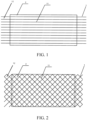
FIG. 1 is a specific schematic structural diagram of Embodiment 1 of a dry battery electrode plate according to an embodiment of the present disclosure; and -
FIG. 2 is a specific schematic structural diagram ofEmbodiment 2 of a dry battery electrode plate according to an embodiment of the present disclosure. - In the drawings: 1 - metal current collector; 11 - metal wire; 12 - pore; 2 - self-supporting electrode film.
- Various exemplary embodiments of the present disclosure are now be described in detail with reference to the accompanying drawings. It should be noted that unless otherwise specified, opposite arrangement, numerical expressions, and numerical values of components and steps described in the embodiments do not limit the scope of the present disclosure.
- The following descriptions of at least one exemplary embodiment are merely illustrative, and in no way constitute any limitation on the present disclosure and application or use of the present disclosure.
- Technologies, methods, and devices known to those of ordinary skill in related arts may not be discussed in detail, but where appropriate, the techniques, the methods, and the devices should be considered as a part of the specification.
- In all examples shown and discussed herein, any specific value should be construed as merely exemplary and not as limitations. Therefore, other examples of exemplary embodiments may have different values.
- It should be noted that like numerals and letters denote like terms in the following drawings. Therefore, once an item is defined in one accompanying drawing, the item does not need to be further discussed in the subsequent accompanying drawings.
- A dry battery electrode plate is provided, including a metal current collector 1 and a self-supporting
electrode film 2. - The metal current collector 1 is made of a metal material such as Cu, Al, Ni, Fe, etc. The metal current collector 1 is provided with
pores 12. Thepores 12 run through the metal current collector 1. Thepores 12 are configured for solid, gas, and liquid materials to pass through the metal current collector 1. - The metal current collector 1 may be a complete piece of metal material provided with
pores 12, or may be formed by metal materials arranged in an array, with thepores 12 being formed between the metal materials. - Two sides of the metal current collector 1 are each provided with the self-supporting
electrode film 2. The self-supportingelectrode film 2 includes a first electrode film and a second electrode film. The first electrode film is arranged on one side of the metal current collector 1. The second electrode film is arranged on one side of the metal current collector 1 facing away from the first electrode film. One side of each of the first electrode film and the second electrode film close to the metal current collector 1 is attached to the metal current collector 1. - The first electrode film and the second electrode film are configured to be press-fit connected by an external force. After the first electrode film and the second electrode film are compressed by a force, the side of the first electrode film attached to the metal current collector 1 and the side of the second electrode film attached to the metal current collector 1 are connected to each other at positions corresponding to the
pores 12. The metal current collector 1 is located between the first electrode film and the second electrode film, thereby achieving connection between the first electrode film, the second electrode film, and the metal current collector 1. - Through the arrangement of the
pores 12 on the metal current collector 1, when the self-supportingelectrode film 2 is press-fit by a force, the first electrode film and the second electrode film are deformed to connect to each other through thepores 12. In addition, it is not necessary to consider whether thicknesses of the first electrode film and the second electrode film are the same, and the first electrode film and the second electrode film will be uniformly dispersed through thepores 12 during the press-fit process. - The self-supporting
electrode film 2 is prepared by a dry process. First, an electrode material, a conductive agent, a binder, and other raw materials are mixed and dispersed to form a dough-like composite slurry. Then, the composite slurry is extruded and calendered to form a continuous self-supportingelectrode film 2. - The electrode material includes a positive electrode material and a negative electrode material. The positive electrode material is selected from at least one of LiCoO2, LiNiO2, LiCoxNi1-xO2 (where 0≤x≤1), LiCoxNi1-x-yAlyO2 (where 0≤x≤1, and 0≤y≤1), LiMn2O4, LiFexMnyMzO4 (where M is at least one of Al, Mg, Ga, Cr, Co, Ni, Cu, Zn, or Mo, 0≤x≤1, 0≤y≤1, 0≤z≤1, and x+y+z=1), Li1+xL1-y-zMyNzO2 (where L, M, and N are each independently at least one of Li, Co, Mn, Ni, Fe, Al, Mg, Ga, Ti, Cr, Cu, Zn, Mo, F, I, S, or B, -0.1<x<0.2, 0≤y≤1, 0≤z≤1, and 0≤y+z≤1), LiFePO4, Li3V2(PO4)3, Li3V3(PO4)3, LiVPO4F, Li2CuO2, Li5FeO4, a metal sulfide (e.g., TiS2, V2S3, FeS, FeS2, or LiMSx (where M is at least one of transition metal elements such as Ti, Fe, Ni, Cu, and Mo, and 1≤x≤2.5)), and an oxide (e.g., TiO2, Cr3O8, V2O5, or MnO2).
- The negative electrode material is selected from one or more of a carbon material, Si, SiOx (0.1<x<1.5), Si-C, SiOx-C (0.1≤x≤1.5), Li4Ti5O12, tin alloy, silicon alloy, silicon, tin, germanium, or indium. The above materials are negative electrode active materials in which lithium intercalation may occur in the art.
- The conductive agent is selected from at least one of carbon black, conductive graphite, carbon nanotubes, carbon fibers, and graphene.
- The binder is selected from at least one of the following materials:
- 1. fluoropolymers (PTFE), and polyolefins (polyethylene (PE), polypropylene (PP), polyvinylidene fluoride (PVDF) copolymers, and/or mixtures thereof);
- 2. composite binders, including: PTFE and polyolefins, polyethers, polyether precursors, polysiloxanes, polysiloxanes and copolymers thereof; PTFE and branched polyethers, polyvinyl ethers and copolymers thereof; or PTFE and polyethylene oxide (PEO), polyphenylene ether (PPO), polyethylene-block-poly(ethylene glycol), polydimethylsiloxane (PDMS), poly(dimethylsiloxane-co-alkylmethylsiloxane) and combinations thereof;
- 3. thermoplastic materials, including polymeric copolymers, olefin oxides, rubber, styrene-butadiene rubber, acrylonitrile-butadiene rubber, polyisobutylene, polyvinyl ester, polyvinyl acetate, polyacrylate, fluorocarbon polymers, etc.
- In the present disclosure, the
pores 12 are provided on the metal current collector 1, and a dry process is used to prepare the self-supportingelectrode film 2. The first electrode film, the metal current collector 1, and the second electrode mold are laminated, and then press-fit by an external force, so that the first electrode film and the second electrode film are connected to each other through thepores 12 on the metal current collector 1, to obtain the battery electrode plate. - In the battery electrode plate of the present disclosure, because the metal current collector 1 is provided with the
pores 12, the metal current collector 1 accounts for a smaller proportion in the whole battery electrode plate, and the self-supportingelectrode film 2 made of the electrode material accounts for a higher proportion, so that the energy density of the whole battery electrode plate is improved. - Because a solvent is used in a wet molding process, the solvent and the binder form a binder layer, and particles of the conductive agent are completely surrounded by the binder layer, hindering the contact between the particles of the conductive agent and between the particles of the conductive agent and particles of the electrode material, and resulting in a poor electrical conductivity of the battery electrode plate. In addition, the residual solvent in the battery electrode plate undergoes side reactions with the electrolyte solution, leading to the degradation of the battery performance, such as capacity reduction, gas generation, shortening of the service life, etc.
- In a dry molding process, no solvent is used, and the binder exists in a fiber state, allowing for a closer contact between the particles of the conductive agent and between the particles of the electrode material and the particles of the conductive agent, thereby achieving a high energy density, good electrical conductivity, and high capacity of the battery electrode plate. In addition, the battery electrode plate prepared by the dry process has better cohesion and adhesion performance in the presence of a high temperature electrolyte solution.
- Preparation of an electrode plate of a battery by a wet process includes five steps: slurry preparation, slurry coating, electrode plate rolling, electrode plate cutting, and electrode plate drying. Electrode plate rolling is used for compacting an electrode material coated on a surface of a current collector of the battery. In the process of electrode plate rolling, the slurry layer is stretched to produce stress, leading to the stretching of the current collector after rolling. As a result, the electrode plate is likely to curl.
- For the dry battery electrode plate provided by the present disclosure, because the self-supporting
electrode film 2 bears more pressure when a large external force is applied for press-fit, there is no need to consider the problems of foil extension and wrinkling. Therefore, a higher compaction density can be achieved, thereby improving the structural stability of the battery electrode plate. - Further, because the first electrode film and the second electrode film are press-fit connected by the external force, adhesion using an adhesive is not required, thereby reducing processing steps and improving the processing efficiency.
- Optionally, a carbon layer is arranged on a surface of the metal current collector 1. The carbon layer adopts one or more of non-graphitized carbon, graphite, carbon obtained by high-temperature oxidation of polyacetylene polymer materials, pyrolytic carbon, coke, organic polymer sintered matter, or activated carbon.
- The surface of the metal current collector 1 is coated with the carbon layer, and the carbon layer covers the whole surface of the metal current collector 1, thereby facilitating the electrical contact between the metal current collector 1 and the self-supporting
electrode film 2, and improving the overcurrent performance of the battery electrode plate. - Optionally, a metal lithium layer is arranged on a surface of the metal current collector 1.
- Usually, when the battery electrode plate is used as a negative electrode, a layer of metal lithium is plated on the surface of the metal current collector 1. The metal lithium covers the whole surface of the metal current collector 1. After injection of an electrolyte solution, the lithium metal is intercalated in the negative electrode to realize the pre-lithiation of the battery electrode plate.
- Optionally, the metal current collector 1 includes a plurality of
metal wires 11, the plurality ofmetal wires 11 are arranged in an array, andadjacent metal wires 11 are spaced apart from each other. - In a dry battery electrode plate, the metal current collector 1 is formed by a plurality of
metal wires 11 arranged in an array,adjacent metal wires 11 are spaced apart from each other, and a gap is formed betweenadjacent metal wires 11 to form thepore 12. Compared with the manner where pores 12 are opened in the metal current collector 1, in the metal current collector 1 formed by themetal wires 11 arranged in an array, themetal wires 11 occupy a smaller volume, the formed metal current collector 1 occupies a smaller volume in the whole battery electrode plate, and the self-supportingelectrode film 2 occupies a larger volume, thereby achieving a higher energy density of the battery electrode plate. - Optionally, referring to
FIG. 2 , themetal wires 11 are arranged to intersect to form a network structure. Themetal wires 11 include transverse and longitudinal metal wires intersecting each other. The transverse andlongitudinal metal wires 11 may be woven to intersect to form a mesh structure, or may be laminated to intersect to form a mesh structure. - Referring to
FIG. 2 , closed pores 12 are formed between the plurality ofmetal wires 11, and thepores 12 are polygonal. In this embodiment, the metal current collector 1 is a mesh structure formed by a plurality oftransverse metal wires 11 andlongitudinal metal wires 11 intersecting each other, a gap is formed between any twotransverse metal wires 11 and any twolongitudinal metal wires 11. The gaps forms thepore 12, and thepore 12 is quadrilateral. An included angle between twometal wires 11 in different directions is 10° to 90°. When the included angle between themetal wires 11 is 10° to 90°, thepore 12 is of a rhomboid structure. - Optionally, a side length of the
pore 12 is 5 µm to 500 µm, that is, lengths of thetransverse metal wires 11 and thelongitudinal metal wires 11 constituting thepore 12 ranges from 5 µm to 500 µm. - Optionally, the side length of the
pore 12 is 5 µm to 200 µm. - An area of the
pore 12 is related to a connection area between the first electrode film and the second electrode film. When the side length of thepore 12 ranges from 5 µm to 200 µm, an effective connection area can be achieved between the first electrode film and the second electrode film, thereby ensuring the stability of connection between the first electrode film and the second electrode film. - Moreover, when the side length of the
pore 12 ranges from 5 µm to 200 µm, distances between the plurality ofmetal wires 11 defining thepores 12 is small, i.e., the plurality ofmetal wires 11 defining thepores 12 can be kept in a dense arrangement structure, and the number ofmetal wires 11 connected to the self-supporting electrode film per unit area can ensure the structural stability of the metal current collector 1. - Optionally, referring to
FIG. 1 , the plurality of themetal wires 11 are arranged in parallel, and thepore 12 is formed between any twoadjacent metal wires 11. The metal current collector 1 is formed by a plurality ofparallel metal wires 11. In this case, a gap betweenadjacent metal wires 11 is thepore 12. The plurality ofmetal wires 11 are arranged side by side between the first electrode film and the second electrode film, and are press-fit by an external force to form the battery electrode plate. - Optionally, a spacing between
adjacent metal wires 11 is 5 µm to 500 µm. - Optionally, a spacing between
adjacent metal wires 11 is 5 µm to 200 µm. - When the spacing between adjacent and
parallel metal wires 11 is within this range, the strength of the metal current collector 1 can be ensured, the volume ratio of the metal current collector 1 to the battery electrode plate can be reduced, and the volume ratio of the self-supportingelectrode film 2 to the battery electrode plate can be increased, thereby improving the energy density of the battery electrode plate. - Optionally, a diameter of the
metal wire 11 is 1 µm to 100 µm. - Optionally, the diameter of the
metal wire 11 is 5 µm to 50 µm. - When the diameter of the
metal wire 11 is within this range, good mechanical properties can be achieved, and the volume ratio of the metal current collector 1 formed by themetal wires 11 to the battery electrode plate can be reduced, and the volume ratio of the self-supportingelectrode film 2 to the battery electrode plate can be increased, thereby improving the energy density of the battery electrode plate. - Optionally, the metal current collector 1 and the self-supporting
electrode film 2 are configured to be fixedly connected by hot rolling. The first electrode film, the metal current collector 1, and the second electrode film are laminated in sequence, hot-rolled by a roller press, and cooled to obtain the dry battery electrode plate. - The dry battery electrode plate prepared by hot rolling has the following advantages.
- 1. Moisture in the self-supporting
electrode film 2 is reduced during heating, so that after the self-supportingelectrode film 2 and the metal current collector 1 are press-fit connected, the battery electrode plate material is less likely to rebound to affect the performance of the battery electrode plate. - 2. During heating, vibration of the binder molecules on the surface of the self-supporting
electrode film 2 is strengthened, the spacing between molecules becomes smaller, the adhesion strength is enhanced, and the self-supportingelectrode film 2 is more tightly connected to the metal current collector 1. Therefore, the adhesion strength between the self-supportingelectrode film 2 and the metal current collector 1 can be increased by hot rolling. - A battery is provided, including the dry battery electrode plate described above.
- Specifically, for the dry battery electrode plate in the battery provided by the present disclosure, because the self-supporting
electrode film 2 bears more pressure when a large external force is applied for press-fit, there is no need to consider the problems of foil extension and wrinkling. Therefore, a higher compaction density can be achieved, thereby improving the structural stability of the battery electrode plate, and ensuring the capacity and stability of the battery. - Although some specific embodiments of the present disclosure have been described in detail by way of examples, a person skilled in the art should understand that the foregoing examples are only for description and are not intended to limit the scope of the present disclosure. A person skilled in the art should appreciate that modifications may be made to the foregoing embodiments without departing from the scope and spirit of the present disclosure. The scope of protection of the present disclosure is defined by the appended claims.
Claims (11)
- A dry battery electrode plate, comprising:a metal current collector (1), the metal current collector (1) being provided with pores (12); anda self-supporting electrode film (2), the self-supporting electrode film (2) comprising a first electrode film and a second electrode film, the first electrode film being arranged on one side of the metal current collector (1), and the second electrode film being arranged on one side of the metal current collector (1) facing away from the first electrode film;the first electrode film and the second electrode film being configured to be press-fit connected by an external force;the first electrode film and the second electrode film being attached to the metal current collector (1), and the first electrode film and the second electrode film being connected to each other at positions corresponding to the pores (12).
- The dry battery electrode plate according to claim 1, wherein a carbon layer is arranged on a surface of the metal current collector (1).
- The dry battery electrode plate according to claim 1 or 2, wherein a metal lithium layer is arranged on a surface of the metal current collector (1).
- The dry battery electrode plate according to any one of claims 1 to 3, wherein the metal current collector (1) comprises a plurality of metal wires (11), the plurality of metal wires (11) are arranged in an array, and adjacent metal wires (11) are spaced apart from each other.
- The dry battery electrode plate according to any one of claims 1 to 4, wherein the metal wires (11) are arranged to intersect to form a network structure, and gaps are formed between the plurality of the metal wires (11) to constitute the pores (12), and the pores (12) are polygonal.
- The dry battery electrode plate according to any one of claims 1 to 5, wherein a side length of the pore (12) is 5 µm to 500 µm.
- The dry battery electrode plate according to any one of claims 1 to 6, wherein the plurality of the metal wires (11) are arranged in parallel, and the pore (12) is formed between any two adjacent metal wires (11).
- The dry battery electrode plate according to any one of claims 1 to 7, wherein a spacing between adjacent metal wires (11) is 5 µm to 500 µm.
- The dry battery electrode plate according to any one of claims 1 to 8, wherein a diameter of the metal wire (11) is 1 µm to 100 µm.
- The dry battery electrode plate according to any one of claims 1 to 9, wherein the metal current collector (1) and the self-supporting electrode film (2) are configured to be fixedly connected by hot rolling.
- A battery, comprising the dry battery electrode plate according to any one of claims 1 to 10.
Applications Claiming Priority (2)
| Application Number | Priority Date | Filing Date | Title |
|---|---|---|---|
| CN202121615791.0U CN215451469U (en) | 2021-07-15 | 2021-07-15 | Dry method battery pole piece |
| PCT/CN2022/105666 WO2023284818A1 (en) | 2021-07-15 | 2022-07-14 | Dry process-based battery pole piece and battery |
Publications (2)
| Publication Number | Publication Date |
|---|---|
| EP4333097A1 true EP4333097A1 (en) | 2024-03-06 |
| EP4333097A4 EP4333097A4 (en) | 2025-07-30 |
Family
ID=79682805
Family Applications (1)
| Application Number | Title | Priority Date | Filing Date |
|---|---|---|---|
| EP22841451.2A Pending EP4333097A4 (en) | 2021-07-15 | 2022-07-14 | DRY PROCESS BATTERY TERMINAL AND BATTERY |
Country Status (9)
| Country | Link |
|---|---|
| US (1) | US20240097142A1 (en) |
| EP (1) | EP4333097A4 (en) |
| JP (1) | JP2024525291A (en) |
| KR (1) | KR20240004824A (en) |
| CN (1) | CN215451469U (en) |
| AU (1) | AU2022309785B2 (en) |
| BR (1) | BR112023026043A2 (en) |
| CA (1) | CA3223286A1 (en) |
| WO (1) | WO2023284818A1 (en) |
Families Citing this family (3)
| Publication number | Priority date | Publication date | Assignee | Title |
|---|---|---|---|---|
| CN215451469U (en) * | 2021-07-15 | 2022-01-07 | 比亚迪股份有限公司 | Dry method battery pole piece |
| DE102022105852A1 (en) * | 2022-03-14 | 2023-09-14 | Bayerische Motoren Werke Aktiengesellschaft | Method for producing an electrode for an electrochemical cell, composite electrode and electrochemical cell |
| CN118610388B (en) * | 2024-05-22 | 2024-12-20 | 江苏天合储能有限公司 | A pole piece and a method for preparing the same |
Family Cites Families (18)
| Publication number | Priority date | Publication date | Assignee | Title |
|---|---|---|---|---|
| JPH07254432A (en) * | 1994-01-25 | 1995-10-03 | Toray Ind Inc | Anode current collector for sodium-sulfur battery and method for producing the same |
| JPH08213026A (en) * | 1994-11-28 | 1996-08-20 | Katayama Tokushu Kogyo Kk | Metallic porous body for battery electrode substrate, battery plate, and manufacture thereof |
| JPH11144738A (en) * | 1997-11-12 | 1999-05-28 | Toshiba Battery Co Ltd | Polymer electrolyte secondary battery |
| CN1215202C (en) * | 2000-11-13 | 2005-08-17 | 松下电器产业株式会社 | Porous nickel foil for negative electrode of alkaline storage battery, method for producing the nickel foil, and production device thereof |
| JP2010097830A (en) * | 2008-10-16 | 2010-04-30 | Nippon Zeon Co Ltd | Manufacturing method of electrode for electrochemical element |
| KR101147241B1 (en) * | 2010-05-20 | 2012-05-18 | 삼성에스디아이 주식회사 | Electrode assembly, rechargeable battery, and fabricating methode of electrode used thereof |
| DE102013201853A1 (en) * | 2013-02-05 | 2014-08-07 | Robert Bosch Gmbh | Electrode for a galvanic element and method for producing the electrode |
| CN110073531B (en) * | 2016-10-28 | 2022-09-02 | 爱德温工业公司 | Conductive flake reinforced, polymer stabilized electrode compositions and methods of making |
| DE102017209960A1 (en) * | 2017-06-13 | 2018-12-13 | Robert Bosch Gmbh | Method for producing an electrode, in particular for a battery |
| JP6990532B2 (en) * | 2017-06-29 | 2022-01-12 | 藤倉コンポジット株式会社 | Air electrode and metal-air battery |
| CN108461756A (en) * | 2017-12-28 | 2018-08-28 | 广州倬粤动力新能源有限公司 | Horizon battery metal material mesh |
| US10797353B2 (en) * | 2018-01-04 | 2020-10-06 | GM Global Technology Operations LLC | Method of manufacturing an electrochemical cell |
| US11502287B2 (en) * | 2018-01-04 | 2022-11-15 | GM Global Technology Operations LLC | Method of manufacturing an electrochemical cell |
| US20200052279A1 (en) * | 2018-08-13 | 2020-02-13 | Tuqiang Chen | Method of preparing energy storage electrodes |
| CN111342053A (en) * | 2020-03-02 | 2020-06-26 | 太仓中科赛诺新能源科技有限公司 | Flexible integrated electrode plate and preparation method and application thereof |
| CN111952679B (en) * | 2020-08-06 | 2022-02-25 | 郜明文 | Battery cell preparation process based on dry film forming |
| CN112466681B (en) * | 2020-11-20 | 2022-01-14 | 东莞东阳光科研发有限公司 | Electrode and preparation method thereof |
| CN215451469U (en) * | 2021-07-15 | 2022-01-07 | 比亚迪股份有限公司 | Dry method battery pole piece |
-
2021
- 2021-07-15 CN CN202121615791.0U patent/CN215451469U/en active Active
-
2022
- 2022-07-14 WO PCT/CN2022/105666 patent/WO2023284818A1/en not_active Ceased
- 2022-07-14 AU AU2022309785A patent/AU2022309785B2/en active Active
- 2022-07-14 EP EP22841451.2A patent/EP4333097A4/en active Pending
- 2022-07-14 CA CA3223286A patent/CA3223286A1/en active Pending
- 2022-07-14 JP JP2023574120A patent/JP2024525291A/en active Pending
- 2022-07-14 BR BR112023026043A patent/BR112023026043A2/en unknown
- 2022-07-14 KR KR1020237041457A patent/KR20240004824A/en active Pending
-
2023
- 2023-11-29 US US18/523,574 patent/US20240097142A1/en active Pending
Also Published As
| Publication number | Publication date |
|---|---|
| EP4333097A4 (en) | 2025-07-30 |
| BR112023026043A2 (en) | 2024-03-05 |
| CA3223286A1 (en) | 2023-01-19 |
| US20240097142A1 (en) | 2024-03-21 |
| AU2022309785B2 (en) | 2025-08-07 |
| WO2023284818A1 (en) | 2023-01-19 |
| CN215451469U (en) | 2022-01-07 |
| JP2024525291A (en) | 2024-07-12 |
| AU2022309785A1 (en) | 2024-01-18 |
| KR20240004824A (en) | 2024-01-11 |
Similar Documents
| Publication | Publication Date | Title |
|---|---|---|
| US20240097142A1 (en) | Dry battery electrode plate and battery | |
| CN110546787B (en) | Positive electrode, secondary battery including the same, and method for manufacturing the same | |
| CN114556611B (en) | Negative electrode and secondary battery containing said negative electrode | |
| KR102095008B1 (en) | Negative electrode, secondary battery, battery module and battery pack comprising the same | |
| CN104067417B (en) | Electrode for secondary battery, secondary battery including same, and cable-type secondary battery | |
| US10741878B2 (en) | Non-aqueous electrolyte and lithium secondary battery including the same | |
| JP7536069B2 (en) | Electrode, lithium battery including same, and method of manufacturing same | |
| JP5163439B2 (en) | FIBER-CONTAINING POLYMER FILM AND METHOD FOR PRODUCING SAME, ELECTROCHEMICAL DEVICE AND METHOD FOR PRODUCING SAME | |
| KR101618218B1 (en) | An Electrochemical Device Comprising The Nano-Fiber Membrane Cellulose And Preparation Method Thereof | |
| JP2023520192A (en) | secondary battery | |
| EP3624243A1 (en) | Bipolar secondary battery | |
| KR102771681B1 (en) | Negative electrode and secondary battery comprising the negative electrode | |
| CN111937210B (en) | Method for manufacturing battery | |
| KR20210058172A (en) | Negative electrode and secondary battery comprising the negative electrode | |
| CN111527627A (en) | Method for manufacturing negative electrode and negative electrode obtained therefrom | |
| KR20220061641A (en) | Negative electrode and method of pre-lithiating a negative electrode | |
| EP4037010A1 (en) | Electrode for secondary battery, and secondary battery comprising same | |
| KR102264546B1 (en) | Electrode assembly for secondary battery | |
| KR20230157243A (en) | All solid battery | |
| WO2019198495A1 (en) | Battery production method | |
| KR102872092B1 (en) | Method for manufacturing an electrode having a resistance layer | |
| CN116779947A (en) | Lithium-ion battery and preparation method thereof | |
| JP2012104274A (en) | Electrode, battery, and manufacturing method of electrode | |
| JP2025524068A (en) | Secondary battery manufacturing method | |
| CN117613357A (en) | Solid composite electrolyte membrane and preparation method thereof, battery |
Legal Events
| Date | Code | Title | Description |
|---|---|---|---|
| STAA | Information on the status of an ep patent application or granted ep patent |
Free format text: STATUS: THE INTERNATIONAL PUBLICATION HAS BEEN MADE |
|
| PUAI | Public reference made under article 153(3) epc to a published international application that has entered the european phase |
Free format text: ORIGINAL CODE: 0009012 |
|
| STAA | Information on the status of an ep patent application or granted ep patent |
Free format text: STATUS: REQUEST FOR EXAMINATION WAS MADE |
|
| 17P | Request for examination filed |
Effective date: 20231128 |
|
| AK | Designated contracting states |
Kind code of ref document: A1 Designated state(s): AL AT BE BG CH CY CZ DE DK EE ES FI FR GB GR HR HU IE IS IT LI LT LU LV MC MK MT NL NO PL PT RO RS SE SI SK SM TR |
|
| DAV | Request for validation of the european patent (deleted) | ||
| DAX | Request for extension of the european patent (deleted) | ||
| A4 | Supplementary search report drawn up and despatched |
Effective date: 20250702 |
|
| RIC1 | Information provided on ipc code assigned before grant |
Ipc: H01M 4/13 20100101AFI20250626BHEP |