EP4332940A1 - Measurement device and method for transmitting output of sensor in measurement device - Google Patents
Measurement device and method for transmitting output of sensor in measurement device Download PDFInfo
- Publication number
- EP4332940A1 EP4332940A1 EP22824583.3A EP22824583A EP4332940A1 EP 4332940 A1 EP4332940 A1 EP 4332940A1 EP 22824583 A EP22824583 A EP 22824583A EP 4332940 A1 EP4332940 A1 EP 4332940A1
- Authority
- EP
- European Patent Office
- Prior art keywords
- sensor
- measurement device
- pins
- environmental
- signal processor
- Prior art date
- Legal status (The legal status is an assumption and is not a legal conclusion. Google has not performed a legal analysis and makes no representation as to the accuracy of the status listed.)
- Withdrawn
Links
Images

Classifications
-
- H—ELECTRICITY
- H04—ELECTRIC COMMUNICATION TECHNIQUE
- H04Q—SELECTING
- H04Q9/00—Arrangements in telecontrol or telemetry systems for selectively calling a substation from a main station, in which substation desired apparatus is selected for applying a control signal thereto or for obtaining measured values therefrom
-
- H—ELECTRICITY
- H04—ELECTRIC COMMUNICATION TECHNIQUE
- H04Q—SELECTING
- H04Q2209/00—Arrangements in telecontrol or telemetry systems
- H04Q2209/30—Arrangements in telecontrol or telemetry systems using a wired architecture
Definitions
- the present invention relates to a measurement device and a method for transmitting sensor output in the measurement device.
- an environmental information acquisition device (10) which is convenient and expensive and is used for applications such as agriculture.
- a device including: an environmental information acquisition unit (11) that communicates with an environmental sensor (20) configured to include one or more sensors to acquire environmental information; a storage unit (12) that stores the environmental information acquired by the environmental information acquisition unit; and a transmission processing unit (11) that transmits the environmental information stored in the storage unit to the outside (e.g., see Patent Document 1).
- an environmental measurement device that corrects a difference in measurement time among various types of environmental data has been proposed.
- a device including: a plurality of environmental sensors (S1 to Sn) that respectively detect a plurality of types of environmental information; conversion units (C1 to Cn) that are provided for the respective environmental sensor and convert the detection signals of the respective environmental sensors into predetermined environmental data; and a processor (P) that collects the environmental data from each of the conversion units and transmits the collected environmental data to a management device (KS) at a remote location via a communication network (N).
- the processor collects environmental data with the same time by providing common time information to each of the conversion units simultaneously (e.g., see Patent Document 2).
- environmental information acquisition devices and environmental measurement devices that enable environmental measurement using one or more sensors, as described in the above patent documents, have become widespread.
- the environmental devices as described above are often required to be configured such that the sensor matches a device to which the sensor is connected, such as a signal processor (or sensor adapter).
- the matching of the sensor with the device to which the sensor is connected is easy for the user of the measurement device.
- the present invention has been made in view of the above problems. Regarding the measurement device as described above, it is the ultimate purpose of the present invention to provide a measurement device that reduces the complexity related to installation of sensors for various measurements or the burden related to the expertise required for installation of sensors for various measurements.
- the present invention for solving the above problems is a measurement device including:
- Pins of the connector unit include a plurality of identification pins for identification of the sensor, and each of the plurality of identification pins is short-circuited using a short-circuit pattern that corresponds to a type of the sensor and/or a type of a communication protocol of the sensor.
- the present invention it is possible to easily recognize, in the signal processor, which type is connected to which and to the signal processor, based on the short-circuit patterns of the plurality of identification pins. It is thus possible to reduce the complexity of installation work by an operator installing the sensor in the measurement device or the burden related to the expertise required for installation of sensors for various measurements.
- the senor may be capable of acquiring measurement data
- the measurement device may include a communication unit configured to transmit the output signal processed by the signal processor.
- the remote computing device may be a personal computer (PC) or a server connected via wireless communication or a wired network.
- the measurement data acquired by the sensor may be visualized to facilitate the management of the site of work by the operator.
- the signal processor may be configured to be applicable to a communication standard of the sensor connected, and a signal compliant with the communication standard may be assigned to a pin other than the identification pin in the connector unit. This makes it possible to selectively use some pins of the connector unit for identifying the sensor and the communication protocol, and the remaining pins for exchanging signals according to the communication standard of the sensor.
- the communication standard here corresponds to a hard interface (IF) of each sensor.
- the signal processor may be configured to be applicable to a communication standard of the sensor connected, and the identification pin in the connector unit may be also used for exchanging a signal compliant with the communication standard.
- the number of pins required for the measurement device is reduced, and a reduction in size and weight of the measurement device can be achieved.
- the communication standard of the sensor may be RS485. This enables the sensor and the signal processor to communicate using general-purpose RS485. As a result, more types of sensors can be connected.
- one type of the communication protocol may be MODBUS RTU. Due to good transmission efficiency of MODBUS RTU, it is possible to quickly and accurately transmit the output information of the short-circuit pattern of each of the plurality of identification pins to the information processor.
- the present invention may be a method for transmitting sensor output in a measurement device that includes one or more sensors, and a signal processor configured to process an output signal of the sensor, the method including identifying a type of the sensor in the signal processor by short-circuiting one of output lines of the sensor, using a short-circuit pattern that corresponds to the type of the sensor and/or a type of a communication protocol of the sensor.
- the measurement device it is possible to reduce the complexity of installation work by an operator installing the sensor or the burden related to the expertise required for installation of sensors for various measurements. As a result, it becomes easier to install the sensor in the measurement device.
- the measurement device according to the present application example is a device used in agriculture to measure environmental parameters that affect agriculture and calculate an index.
- the measurement device in the present invention is not limited thereto.
- Fig. 1 is a schematic view illustrating an example of a measurement device 1 to which the present invention can be applied.
- the measurement device 1 in the present application example includes: a plurality of environmental sensors 2; a plurality of sensor adapters 3, each connected to its corresponding one of the plurality of environmental sensors 2; a communication module 6 that is connected to a battery 4 and transmits a signal to a network in which a cloud service 5 is deployed; and an automatic recognition connector 7 interposed between the environmental sensor 2 and the sensor adapter 3 to enable connection therebetween.
- the environmental sensor 2 in the present application example can acquire various measurement data by using a plurality of sensors.
- the environmental sensor 2 includes, for example, a weather sensor 2a related to measurement of weather, a soil moisture sensor 2b related to measurement of a moisture content of soil, and a water level sensor 2c related to measurement of a water level.
- a plurality of pins are incorporated in the automatic recognition connector 7. Some of the plurality of pins are a group of pins for identifying the environmental sensor 2, and are short-circuited using a short-circuit pattern that corresponds to the type of the environmental sensor 2 connected to the sensor adapter 3. The plurality of pins also include a group of pins for transmitting the output signal of the environmental sensor 2 from the automatic recognition connector 7 to the sensor adapter 3. Fig. 2 and Fig. 3 illustrate details of the plurality of pins incorporated in the automatic recognition connector 7.
- the sensor adapter 3 automatically recognizes the type of the environmental sensor 2 connected to the sensor adapter 3, using a short-circuit pattern of pins for identifying the environmental sensor 2 in the automatic recognition connector 7.
- the circuit of the sensor adapter 3 includes a signal processor 8 in addition to a surge suppression integrated circuit (IC) 3a and an isolator 3b.
- the output signal of the environmental sensor 2 is adjusted in a processable manner in the circuit of the sensor adapter 3 and transmitted to the communication module 6.
- the communication module 6 wirelessly communicates the output signal of the environmental sensor 2, which has been adjusted in a processable manner, to the cloud service 5, using an antenna attached to the communication module 6.
- Calculation processing is applied to environmental parameters, obtained from the environmental sensor 2, in the cloud service 5. In this way, an index of the environmental parameter is obtained, and the index is visualized in the cloud service 5. Visualizing the index makes it easier to manage the agricultural field.
- a measurement device according to a first embodiment of the present invention will be described in detail with reference to the drawings.
- an example of the present invention being applied for agricultural use as an environmental control device will be described.
- the present invention may be applied to other uses, such as factory automation (FA) in a factory.
- FA factory automation
- the measurement device according to the present invention is not intended to be limited to the following configuration.
- the description returns to Fig. 1 .
- the output signal obtained from the environmental sensor 2 is transmitted to the network (cloud), in which the cloud service 5 is deployed, via the automatic recognition connector 7, the sensor adapter 3, and the communication module 6.
- the cloud service 5 performs processing for visualizing the information on the environmental parameters and provides the information to a user.
- the sensor adapter 3 is created depending on the hard IF of each environmental sensor 2.
- the hard IF of the sensor adapter 3 corresponds to RS485.
- the serial communication standard may be other than RS485.
- the length of the output line between each environmental sensor 2 and the automatic recognition connector 7 may be, for example, about 10 m.
- the length of the output line between the automatic recognition connector 7 and the sensor adapter 3 may be, for example, about 5 cm.
- the communication standard from the communication module 6 to the cloud is, for example, NBIoT, CAT.M1, or the like. Note that the information may be transmitted from the communication module 6 to the cloud service 5 via wired communication or wireless communication.
- the environmental sensor 2 corresponds to a sensor in the present invention.
- the communication module 6 particularly corresponds to a communication unit in the present invention.
- the automatic recognition connector 7 corresponds to a connector unit in the present invention.
- the signal output from the environmental sensor 2 and adjusted by the sensor adapter 3 is transmitted via wireless communication by the communication module 6 to a PC or a server operating in the cloud service 5.
- the signal may be directly transmitted from the sensor adapter 3 to the PC or the server in a wired manner.
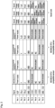
- Fig. 2 is an explanatory diagram of the signal assignment of a plurality of pins incorporated in the automatic recognition connector 7 of the measurement device 1 in the first embodiment.
- the automatic recognition connector 7 in the first embodiment includes eight pins, which will be described below as Pins 1 to 8. Eight pins are connected to the sensor adapter 3 through the output lines, and Pins 2 and 3 are assigned to exchange output information between the environmental sensor 2 and the sensor adapter 3.
- Pin 2 is a pin that enables transmission of a command signal, after being processed in the sensor adapter 3, from the PC or the server in the cloud service 5 to the environmental sensor 2.
- Pin 3 receives the output signal of the environmental sensor 2.
- TxD illustrated in Fig. 2 indicates that the pin is a terminal for transmitting data to the environmental sensor 2.
- RxD represents that the pin is a terminal for receiving data from the environmental sensor 2.
- Y and “Z” illustrated in Fig. 2 indicate that the respective pins are connected to the driver of the inversion output and the non-inversion output in the sensor adapter 3.
- Pin 1 is a pin connected to a power supply
- Pin 4 is a pin connected to a ground G.
- Pins 5 to 8 are used as a group of pins for identifying the environmental sensor 2 connected to the sensor adapter 3.
- Pin 8 is a pin connected to the ground G.
- the measurement device 1 can be connected to both a MODBUS RTU-compatible environmental sensor which is a type of communication protocol, and a MODBUS RTU-incompatible environmental sensor ( Fig. 2 illustrates an environmental sensor A, an environmental sensor B, and an environmental sensor C).
- the manner in which Pins 5 to 8 automatically recognize the environmental sensor 2 varies depending on whether the target of automatic recognition is the MODBUS RTU-compatible environmental sensor or the MODBUS RTU-incompatible environmental sensor.
- the target of the automatic recognition is the MODBUS RTU-compatible environmental sensor
- Pins 5 to 8 of the automatic recognition connector 7 are short-circuited using a common short-circuit pattern.
- the common short-circuit pattern indicates that Pins 5 and 8 are short-circuited in Fig. 2 .
- the target of the automatic recognition is the MODBUS RTU-incompatible environmental sensor
- a short-circuit pattern has been determined for Pins 5 to 8 according to the type of environmental sensor, and the type of MODBUS RTU-incompatible environmental sensor is recognized using this short-circuit pattern.
- Fig. 2 when Pins 6 and 8 are short-circuited, it is automatically recognized that the connected sensor is the environmental sensor A.
- a different IP address has been assigned to each of the environmental sensor A, the environmental sensor B, and the environmental sensor C.
- a communication protocol unique to a manufacturer of each sensor may be used.
- the functions of Pin 1 to Pin 8 and the short-circuit pattern are not limited to those illustrated in Fig. 2 , and the number of pins is not limited to eight.
- seven sensor adapters 3 are provided, and seven types of environmental sensors 2 can be connected. However, the number of sensor adapters 3 and the number of connectable environmental sensors 2 are not limited thereto.
- Pins 5 to 8 are pins that recognize the type of environmental sensor. However, in addition to being pins that recognize the type of environmental sensor, these pins may be shared with pins that exchange signals, such as Pins 2 and 3. In this case, the timing for identifying the sensor and the timing for exchanging signals may be switched in time. At this time, the pins that are used may be enabled, and the pins that are not used may be disabled by bringing the pins into a high impedance state.
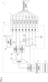
- Fig. 3 is a functional block diagram illustrating the functions of the measurement device 1 in the first embodiment.
- the environmental sensor 2 is connected to the sensor adapter 3 through the output lines via the eight pins incorporated in the automatic recognition connector 7.
- the output lines connected by Pins 2 and 3 pass through the surge suppression IC 3a and the isolator 3b in the sensor adapter 3.
- the surge suppression IC 3a suppresses an abnormally high voltage, which is generated instantaneously, and protects a circuit in the measurement device 1 including the sensor adapter 3.
- the isolator 3b insulates noise generated in the circuit in the sensor adapter 3.
- the output line connected by Pin 1 is connected to the power supply (not illustrated), and is connected to the ground G via an electrostatic discharge (ESD) suppressor 3c, thereby protecting the sensor adapter 3 and the connected environmental sensor 2 from static electricity.
- ESD electrostatic discharge
- Pins 5 to 8 are short-circuited using a short-circuit pattern that corresponds to the type of the environmental sensor 2.
- Fig. 3 is an example of the measurement device 1 in which Pins 5 and 8 are short-circuited, and according to the example illustrated in Fig. 2 , the environmental sensor 2 is recognized as being compatible with MODBUS RTU.
- the output signals output from Pin 2, Pin 3, and Pins 5 to 8 are finally processed by the signal processor 8. Thereafter, as described above, the output signals are transmitted to the PC or the server in the cloud service 5 via wireless communication by the communication module 6, and subjected to signal processing. Even if a surge or noise that is instantaneously generated is included, when little influence is exerted on the function of the signal processor 8, the surge suppression IC 3a or the isolator 3b is not necessarily required. In that case, the sensor adapter 3 corresponds to a signal processor in the present invention.
- the short-circuit pattern in the automatic recognition connector 7 may be set for each type of sensor or for each type of communication protocol.
- a measurement device (1) including:
- a method for transmitting sensor output in a measurement device (1) that includes
Landscapes
- Engineering & Computer Science (AREA)
- Computer Networks & Wireless Communication (AREA)
- Arrangements For Transmission Of Measured Signals (AREA)
Abstract
Description
- The present invention relates to a measurement device and a method for transmitting sensor output in the measurement device.
- Conventionally, there has been proposed an environmental information acquisition device (10), which is convenient and expensive and is used for applications such as agriculture. As the environmental information acquisition device, there is known a device including: an environmental information acquisition unit (11) that communicates with an environmental sensor (20) configured to include one or more sensors to acquire environmental information; a storage unit (12) that stores the environmental information acquired by the environmental information acquisition unit; and a transmission processing unit (11) that transmits the environmental information stored in the storage unit to the outside (e.g., see Patent Document 1).
- Also, an environmental measurement device that corrects a difference in measurement time among various types of environmental data has been proposed. As the environmental measurement device, there is known a device including: a plurality of environmental sensors (S1 to Sn) that respectively detect a plurality of types of environmental information; conversion units (C1 to Cn) that are provided for the respective environmental sensor and convert the detection signals of the respective environmental sensors into predetermined environmental data; and a processor (P) that collects the environmental data from each of the conversion units and transmits the collected environmental data to a management device (KS) at a remote location via a communication network (N). The processor collects environmental data with the same time by providing common time information to each of the conversion units simultaneously (e.g., see Patent Document 2).
- In recent years, environmental information acquisition devices and environmental measurement devices (hereinafter simply referred to as "measurement devices") that enable environmental measurement using one or more sensors, as described in the above patent documents, have become widespread. The environmental devices as described above are often required to be configured such that the sensor matches a device to which the sensor is connected, such as a signal processor (or sensor adapter). Ideally, the matching of the sensor with the device to which the sensor is connected is easy for the user of the measurement device.
-
- Patent Document 1:
Japanese Unexamined Patent Publication No. 2012-027702 - Patent Document 2:
Japanese Unexamined Patent Publication No. 2013-256971 - Patent Document 3:
Japanese Unexamined Patent Publication No. 2012-098901 - Patent Document 4:
Japanese Unexamined Patent Publication No. 2018-151264 - The present invention has been made in view of the above problems. Regarding the measurement device as described above, it is the ultimate purpose of the present invention to provide a measurement device that reduces the complexity related to installation of sensors for various measurements or the burden related to the expertise required for installation of sensors for various measurements.
- The present invention for solving the above problems is a measurement device including:
- one or more sensors;
- a signal processor configured to process an output signal of the sensor; and
- a connector unit interposed between the sensor and the signal processor and configured to connect the sensor and the signal processor.
- Pins of the connector unit include a plurality of identification pins for identification of the sensor, and each of the plurality of identification pins is short-circuited using a short-circuit pattern that corresponds to a type of the sensor and/or a type of a communication protocol of the sensor.
- According to the present invention, it is possible to easily recognize, in the signal processor, which type is connected to which and to the signal processor, based on the short-circuit patterns of the plurality of identification pins. It is thus possible to reduce the complexity of installation work by an operator installing the sensor in the measurement device or the burden related to the expertise required for installation of sensors for various measurements.
- Further, in the present invention, the sensor may be capable of acquiring measurement data, and the measurement device may include a communication unit configured to transmit the output signal processed by the signal processor. Thereby, it is possible to transmit the measurement data acquired by the sensor to a remote computing device and process the measurement data. The remote computing device may be a personal computer (PC) or a server connected via wireless communication or a wired network. In the remote computing device, the measurement data acquired by the sensor may be visualized to facilitate the management of the site of work by the operator.
- Further, in the present invention, the signal processor may be configured to be applicable to a communication standard of the sensor connected, and a signal compliant with the communication standard may be assigned to a pin other than the identification pin in the connector unit. This makes it possible to selectively use some pins of the connector unit for identifying the sensor and the communication protocol, and the remaining pins for exchanging signals according to the communication standard of the sensor. Note that the communication standard here corresponds to a hard interface (IF) of each sensor.
- Further, in the present invention, the signal processor may be configured to be applicable to a communication standard of the sensor connected, and the identification pin in the connector unit may be also used for exchanging a signal compliant with the communication standard. Thereby, the number of pins required for the measurement device is reduced, and a reduction in size and weight of the measurement device can be achieved.
- Further, in the present invention, the communication standard of the sensor may be RS485. This enables the sensor and the signal processor to communicate using general-purpose RS485. As a result, more types of sensors can be connected.
- Further, in the present invention, one type of the communication protocol may be MODBUS RTU. Due to good transmission efficiency of MODBUS RTU, it is possible to quickly and accurately transmit the output information of the short-circuit pattern of each of the plurality of identification pins to the information processor.
- Further, the present invention may be a method for transmitting sensor output in a measurement device that includes one or more sensors, and a signal processor configured to process an output signal of the sensor, the method including identifying a type of the sensor in the signal processor by short-circuiting one of output lines of the sensor, using a short-circuit pattern that corresponds to the type of the sensor and/or a type of a communication protocol of the sensor.
- Note that means for solving the above problems can be used in combination as much as possible.
- According to the present invention, in the measurement device, it is possible to reduce the complexity of installation work by an operator installing the sensor or the burden related to the expertise required for installation of sensors for various measurements. As a result, it becomes easier to install the sensor in the measurement device.
-
-
Fig. 1 is a schematic view illustrating an example of a measurement device in a first embodiment. -
Fig. 2 is an explanatory diagram of a plurality of pins incorporated in an automatic recognition connector of the measurement device in the first embodiment. -
Fig. 3 is a functional block diagram illustrating functions of the measurement device in the first embodiment. - In the present application example, a measurement device equipped with an automatic recognition connector including a pin for identifying an environmental sensor will be described. The measurement device according to the present application example is a device used in agriculture to measure environmental parameters that affect agriculture and calculate an index. However, the measurement device in the present invention is not limited thereto.
-
Fig. 1 is a schematic view illustrating an example of ameasurement device 1 to which the present invention can be applied. Themeasurement device 1 in the present application example includes: a plurality ofenvironmental sensors 2; a plurality ofsensor adapters 3, each connected to its corresponding one of the plurality ofenvironmental sensors 2; acommunication module 6 that is connected to abattery 4 and transmits a signal to a network in which acloud service 5 is deployed; and anautomatic recognition connector 7 interposed between theenvironmental sensor 2 and thesensor adapter 3 to enable connection therebetween. Theenvironmental sensor 2 in the present application example can acquire various measurement data by using a plurality of sensors. Theenvironmental sensor 2 includes, for example, aweather sensor 2a related to measurement of weather, asoil moisture sensor 2b related to measurement of a moisture content of soil, and awater level sensor 2c related to measurement of a water level. - A plurality of pins are incorporated in the
automatic recognition connector 7. Some of the plurality of pins are a group of pins for identifying theenvironmental sensor 2, and are short-circuited using a short-circuit pattern that corresponds to the type of theenvironmental sensor 2 connected to thesensor adapter 3. The plurality of pins also include a group of pins for transmitting the output signal of theenvironmental sensor 2 from theautomatic recognition connector 7 to thesensor adapter 3.Fig. 2 andFig. 3 illustrate details of the plurality of pins incorporated in theautomatic recognition connector 7. - In
Fig. 1 , thesensor adapter 3 automatically recognizes the type of theenvironmental sensor 2 connected to thesensor adapter 3, using a short-circuit pattern of pins for identifying theenvironmental sensor 2 in theautomatic recognition connector 7. The circuit of thesensor adapter 3 includes asignal processor 8 in addition to a surge suppression integrated circuit (IC) 3a and anisolator 3b. The output signal of theenvironmental sensor 2 is adjusted in a processable manner in the circuit of thesensor adapter 3 and transmitted to thecommunication module 6. Thecommunication module 6 wirelessly communicates the output signal of theenvironmental sensor 2, which has been adjusted in a processable manner, to thecloud service 5, using an antenna attached to thecommunication module 6. Calculation processing is applied to environmental parameters, obtained from theenvironmental sensor 2, in thecloud service 5. In this way, an index of the environmental parameter is obtained, and the index is visualized in thecloud service 5. Visualizing the index makes it easier to manage the agricultural field. - Hereinafter, a measurement device according to a first embodiment of the present invention will be described in detail with reference to the drawings. In the following embodiment, an example of the present invention being applied for agricultural use as an environmental control device will be described. However, the present invention may be applied to other uses, such as factory automation (FA) in a factory. Note that the measurement device according to the present invention is not intended to be limited to the following configuration.
- Here, the description returns to
Fig. 1 . As described above, the output signal obtained from theenvironmental sensor 2 is transmitted to the network (cloud), in which thecloud service 5 is deployed, via theautomatic recognition connector 7, thesensor adapter 3, and thecommunication module 6. Thecloud service 5 performs processing for visualizing the information on the environmental parameters and provides the information to a user. Regarding the serial communication standard between theenvironmental sensor 2 and thesensor adapter 3, thesensor adapter 3 is created depending on the hard IF of eachenvironmental sensor 2. In themeasurement device 1 according to the first embodiment, the hard IF of thesensor adapter 3 corresponds to RS485. Note that the serial communication standard may be other than RS485. - The length of the output line between each
environmental sensor 2 and theautomatic recognition connector 7 may be, for example, about 10 m. The length of the output line between theautomatic recognition connector 7 and thesensor adapter 3 may be, for example, about 5 cm. The communication standard from thecommunication module 6 to the cloud is, for example, NBIoT, CAT.M1, or the like. Note that the information may be transmitted from thecommunication module 6 to thecloud service 5 via wired communication or wireless communication. Here, theenvironmental sensor 2 corresponds to a sensor in the present invention. - The
communication module 6 particularly corresponds to a communication unit in the present invention. Theautomatic recognition connector 7 corresponds to a connector unit in the present invention. In the embodiment, the signal output from theenvironmental sensor 2 and adjusted by thesensor adapter 3 is transmitted via wireless communication by thecommunication module 6 to a PC or a server operating in thecloud service 5. However, the signal may be directly transmitted from thesensor adapter 3 to the PC or the server in a wired manner. -
Fig. 2 is an explanatory diagram of the signal assignment of a plurality of pins incorporated in theautomatic recognition connector 7 of themeasurement device 1 in the first embodiment. Theautomatic recognition connector 7 in the first embodiment includes eight pins, which will be described below asPins 1 to 8. Eight pins are connected to thesensor adapter 3 through the output lines, and Pins 2 and 3 are assigned to exchange output information between theenvironmental sensor 2 and thesensor adapter 3. - More specifically,
Pin 2 is a pin that enables transmission of a command signal, after being processed in thesensor adapter 3, from the PC or the server in thecloud service 5 to theenvironmental sensor 2.Pin 3 receives the output signal of theenvironmental sensor 2. Note that "TxD" illustrated inFig. 2 indicates that the pin is a terminal for transmitting data to theenvironmental sensor 2. In addition, "RxD" represents that the pin is a terminal for receiving data from theenvironmental sensor 2. Further, "Y" and "Z" illustrated inFig. 2 indicate that the respective pins are connected to the driver of the inversion output and the non-inversion output in thesensor adapter 3.Pin 1 is a pin connected to a power supply, andPin 4 is a pin connected to a ground G. - Among the eight pins,
Pins 5 to 8 are used as a group of pins for identifying theenvironmental sensor 2 connected to thesensor adapter 3.Pin 8 is a pin connected to the ground G. Themeasurement device 1 can be connected to both a MODBUS RTU-compatible environmental sensor which is a type of communication protocol, and a MODBUS RTU-incompatible environmental sensor (Fig. 2 illustrates an environmental sensor A, an environmental sensor B, and an environmental sensor C). The manner in which Pins 5 to 8 automatically recognize theenvironmental sensor 2 varies depending on whether the target of automatic recognition is the MODBUS RTU-compatible environmental sensor or the MODBUS RTU-incompatible environmental sensor. - In the embodiment, in a case where the target of the automatic recognition is the MODBUS RTU-compatible environmental sensor, Pins 5 to 8 of the
automatic recognition connector 7 are short-circuited using a common short-circuit pattern. The common short-circuit pattern indicates thatPins Fig. 2 . In other words, whenPins Pins 5 to 8 according to the type of environmental sensor, and the type of MODBUS RTU-incompatible environmental sensor is recognized using this short-circuit pattern. - For example, in
Fig. 2 , whenPins Pin 1 to Pin 8 and the short-circuit pattern are not limited to those illustrated inFig. 2 , and the number of pins is not limited to eight. As illustrated inFig. 2 , in the embodiment, sevensensor adapters 3 are provided, and seven types ofenvironmental sensors 2 can be connected. However, the number ofsensor adapters 3 and the number of connectableenvironmental sensors 2 are not limited thereto. - In
Fig. 2 , Pins 5 to 8 are pins that recognize the type of environmental sensor. However, in addition to being pins that recognize the type of environmental sensor, these pins may be shared with pins that exchange signals, such asPins -
Fig. 3 is a functional block diagram illustrating the functions of themeasurement device 1 in the first embodiment. As described above, in themeasurement device 1, theenvironmental sensor 2 is connected to thesensor adapter 3 through the output lines via the eight pins incorporated in theautomatic recognition connector 7. InFig. 3 , the output lines connected byPins surge suppression IC 3a and theisolator 3b in thesensor adapter 3. Thesurge suppression IC 3a suppresses an abnormally high voltage, which is generated instantaneously, and protects a circuit in themeasurement device 1 including thesensor adapter 3. Theisolator 3b insulates noise generated in the circuit in thesensor adapter 3. - The output line connected by
Pin 1 is connected to the power supply (not illustrated), and is connected to the ground G via an electrostatic discharge (ESD) suppressor 3c, thereby protecting thesensor adapter 3 and the connectedenvironmental sensor 2 from static electricity. As also illustrated inFig. 2 , Pins 5 to 8 are short-circuited using a short-circuit pattern that corresponds to the type of theenvironmental sensor 2.Fig. 3 is an example of themeasurement device 1 in which Pins 5 and 8 are short-circuited, and according to the example illustrated inFig. 2 , theenvironmental sensor 2 is recognized as being compatible with MODBUS RTU. - The output signals output from
Pin 2,Pin 3, and Pins 5 to 8 are finally processed by thesignal processor 8. Thereafter, as described above, the output signals are transmitted to the PC or the server in thecloud service 5 via wireless communication by thecommunication module 6, and subjected to signal processing. Even if a surge or noise that is instantaneously generated is included, when little influence is exerted on the function of thesignal processor 8, thesurge suppression IC 3a or theisolator 3b is not necessarily required. In that case, thesensor adapter 3 corresponds to a signal processor in the present invention. The short-circuit pattern in theautomatic recognition connector 7 may be set for each type of sensor or for each type of communication protocol. - To enable a comparison between the constituent elements of the present invention and the configurations of the embodiments, the constituent elements of the present invention will be described below with reference signs in the drawings.
- A measurement device (1) including:
- one or more sensors (2);
- a signal processor (8) configured to process an output signal of the sensor; and
- a connector unit (7) interposed between the sensor and the signal processor and configured to connect the sensor and the signal processor,
- in which pins of the connector unit include a plurality of identification pins for identification of the sensor, and each of the plurality of identification pins is short-circuited using a short-circuit pattern that corresponds to a type of the sensor and/or a type of a communication protocol of the sensor.
- A method for transmitting sensor output in a measurement device (1) that includes
- one or more sensors (2), and
- a signal processor (8) configured to process an output signal of the sensor,
- the method including
- identifying a type of the sensor in the signal processor by short-circuiting one of output lines of the sensor, using a short-circuit pattern that corresponds to the type of the sensor and/or a type of a communication protocol of the sensor.
-
- 1
- measurement device
- 2
- environmental sensor
- 2a
- weather sensor
- 2b
- soil moisture sensor
- 2c
- water level sensor
- 3
- sensor adapter
- 3a
- surge suppression IC
- 3b
- isolator
- 3c
- ESD suppressor
- 4
- battery
- 5
- cloud service
- 6
- communication module
- 7
- automatic recognition connector
- 8
- signal processor
Claims (7)
- A measurement device comprising:one or more sensors;a signal processor configured to process an output signal of the sensor; anda connector unit interposed between the sensor and the signal processor and configured to connect the sensor and the signal processor,wherein pins of the connector unit comprise a plurality of identification pins for identification of the sensor, and each of the plurality of identification pins is short-circuited using a short-circuit pattern that corresponds to a type of the sensor and/or a type of a communication protocol of the sensor.
- The measurement device according to claim 1, whereinthe sensor is capable of acquiring measurement data, andthe measurement device further comprises a communication unit configured to transmit the output signal processed by the signal processor.
- The measurement device according to claim 1 or 2, whereinthe signal processor is configured to be applicable to a communication standard of the sensor connected, anda signal compliant with the communication standard is assigned to a pin other than the identification pin in the connector unit.
- The measurement device according to claim 1 or 2, whereinthe signal processor is configured to be applicable to a communication standard of the sensor connected, andthe identification pin in the connector unit is also used for exchanging a signal compliant with the communication standard.
- The measurement device according to claim 1 or 2, wherein a communication standard of the sensor is RS485.
- The measurement device according to any one of claims 1 to 5, wherein one type of the communication protocol is MODBUS RTU.
- A method for transmitting sensor output in a measurement device that comprises one or more sensors, anda signal processor configured to process an output signal of the sensor,the method comprisingidentifying a type of the sensor in the signal processor by short-circuiting one of output lines of the sensor, using a short-circuit pattern that corresponds to the type of the sensor and/or a type of a communication protocol of the sensor.
Applications Claiming Priority (2)
| Application Number | Priority Date | Filing Date | Title |
|---|---|---|---|
| JP2021098540A JP2022190284A (en) | 2021-06-14 | 2021-06-14 | Measuring device and method for transmitting sensor output in measuring device |
| PCT/JP2022/012801 WO2022264587A1 (en) | 2021-06-14 | 2022-03-18 | Measurement device and method for transmitting output of sensor in measurement device |
Publications (2)
| Publication Number | Publication Date |
|---|---|
| EP4332940A1 true EP4332940A1 (en) | 2024-03-06 |
| EP4332940A4 EP4332940A4 (en) | 2025-05-07 |
Family
ID=84527038
Family Applications (1)
| Application Number | Title | Priority Date | Filing Date |
|---|---|---|---|
| EP22824583.3A Withdrawn EP4332940A4 (en) | 2021-06-14 | 2022-03-18 | MEASURING DEVICE AND METHOD FOR TRANSMITTING THE OUTPUT OF A SENSOR IN THE MEASURING DEVICE |
Country Status (5)
| Country | Link |
|---|---|
| US (1) | US20240276126A1 (en) |
| EP (1) | EP4332940A4 (en) |
| JP (1) | JP2022190284A (en) |
| CN (1) | CN117355878A (en) |
| WO (1) | WO2022264587A1 (en) |
Families Citing this family (1)
| Publication number | Priority date | Publication date | Assignee | Title |
|---|---|---|---|---|
| CN115801915B (en) * | 2023-02-07 | 2023-05-05 | 南京九维测控科技有限公司 | Automatic data communication protocol adapting interface between digital sensor and host |
Family Cites Families (13)
| Publication number | Priority date | Publication date | Assignee | Title |
|---|---|---|---|---|
| JP3458905B2 (en) * | 1993-09-30 | 2003-10-20 | 株式会社島津製作所 | Magnetic bearing device |
| JPH08320748A (en) * | 1995-05-24 | 1996-12-03 | Japan Aviation Electron Ind Ltd | Sensor processing device and system |
| JP2000019147A (en) * | 1998-07-01 | 2000-01-21 | Nok Corp | Reaction product measuring device |
| JP2005309742A (en) * | 2004-04-21 | 2005-11-04 | Takachiho Sangyo Kk | Environmental measuring device |
| JP2012027702A (en) | 2010-07-23 | 2012-02-09 | Nippon Seiki Co Ltd | Environmental information acquisition device, portable terminal, environmental information gathering system and program |
| JP2012098901A (en) | 2010-11-02 | 2012-05-24 | Hitachi Ltd | Environmental monitoring system |
| JP2013256971A (en) | 2012-06-11 | 2013-12-26 | Hitachi Constr Mach Co Ltd | Piping structure in housing |
| US10342163B2 (en) * | 2015-12-02 | 2019-07-02 | Google Llc | Cooling a data center |
| WO2017105699A1 (en) * | 2015-12-16 | 2017-06-22 | Pillar Technologies, Inc. | Systems and methods for providing environmental monitoring and response measures in connection with remote sites |
| JP6680546B2 (en) * | 2016-01-26 | 2020-04-15 | 日本特殊陶業株式会社 | Measuring device |
| KR102657535B1 (en) * | 2016-11-24 | 2024-04-15 | 삼성전자주식회사 | Electronic apparatus and operating method thereof |
| JP6838435B2 (en) | 2017-03-13 | 2021-03-03 | オムロン株式会社 | Environment sensor |
| BE1026569B1 (en) * | 2018-08-27 | 2020-03-23 | Phoenix Contact Gmbh & Co | Control and data transmission system to support various communication protocols and an adapter module |
-
2021
- 2021-06-14 JP JP2021098540A patent/JP2022190284A/en not_active Withdrawn
-
2022
- 2022-03-18 CN CN202280037105.7A patent/CN117355878A/en active Pending
- 2022-03-18 WO PCT/JP2022/012801 patent/WO2022264587A1/en not_active Ceased
- 2022-03-18 US US18/564,220 patent/US20240276126A1/en not_active Abandoned
- 2022-03-18 EP EP22824583.3A patent/EP4332940A4/en not_active Withdrawn
Also Published As
| Publication number | Publication date |
|---|---|
| CN117355878A (en) | 2024-01-05 |
| WO2022264587A1 (en) | 2022-12-22 |
| US20240276126A1 (en) | 2024-08-15 |
| JP2022190284A (en) | 2022-12-26 |
| EP4332940A4 (en) | 2025-05-07 |
Similar Documents
| Publication | Publication Date | Title |
|---|---|---|
| CN102027330B (en) | Data acquisition module and system | |
| JP5584118B2 (en) | Data acquisition system and method for automatically performing diagnostic inspection of process equipment using the data acquisition system | |
| US6105093A (en) | Interface monitor for communicating between different communication protocols | |
| US12399201B2 (en) | Modular sensor platform apparatus | |
| US20240276126A1 (en) | Measurement device and method for transmitting output of sensor in measurement device | |
| EP2954696A1 (en) | Dedicated network diagnostics module for a process network | |
| KR20260048488A (en) | Operation method between AMI device and modem in advanced metering infrastructure system | |
| CN209786878U (en) | Intelligent power distribution room online monitoring system | |
| JP3100335B2 (en) | Sensor signal processing module | |
| CN214202630U (en) | Magnetic force detection device | |
| WO2017189954A1 (en) | Base station antenna unified system for sensors and test calls | |
| CN119476337A (en) | A multi-RFID tag sensing method, system, terminal and storage medium | |
| US20030151489A1 (en) | Using a wireless interface for monitoring, maintenance, and control of devices | |
| WO2011028096A1 (en) | Zigbee-can integrated system for precision agriculture | |
| CN113938536A (en) | Multi-protocol and multi-connection mode commercial vehicle fault diagnosis instrument adapter | |
| CN106657275A (en) | Internet of Things sensing module with information processing based on narrow-band communication | |
| US20150155956A1 (en) | Procedure and arrangement for testing the operational state of a process tool | |
| CN118444070A (en) | Distributed cable fault accurate positioning on-line monitoring system | |
| CN106408773A (en) | Electricity meter using Internet of Things sensing module with information processing | |
| CN113438144A (en) | Ethernet bus data acquisition system, method, storage medium and computer equipment | |
| US20120010856A1 (en) | Wireless data retrieval and collection system and methods therefor | |
| CN106600926A (en) | Calorimeter using internet-of-things sensing module | |
| CN114793141B (en) | Performance test system based on built-in antenna | |
| CN213545525U (en) | Novel wireless communication device suitable for photovoltaic combiner box measurement and control equipment | |
| CN110162017B (en) | Vehicle LIN bus communication information abnormity diagnosis system and method |
Legal Events
| Date | Code | Title | Description |
|---|---|---|---|
| STAA | Information on the status of an ep patent application or granted ep patent |
Free format text: STATUS: THE INTERNATIONAL PUBLICATION HAS BEEN MADE |
|
| PUAI | Public reference made under article 153(3) epc to a published international application that has entered the european phase |
Free format text: ORIGINAL CODE: 0009012 |
|
| STAA | Information on the status of an ep patent application or granted ep patent |
Free format text: STATUS: REQUEST FOR EXAMINATION WAS MADE |
|
| 17P | Request for examination filed |
Effective date: 20231127 |
|
| AK | Designated contracting states |
Kind code of ref document: A1 Designated state(s): AL AT BE BG CH CY CZ DE DK EE ES FI FR GB GR HR HU IE IS IT LI LT LU LV MC MK MT NL NO PL PT RO RS SE SI SK SM TR |
|
| DAV | Request for validation of the european patent (deleted) | ||
| DAX | Request for extension of the european patent (deleted) | ||
| STAA | Information on the status of an ep patent application or granted ep patent |
Free format text: STATUS: THE APPLICATION HAS BEEN WITHDRAWN |
|
| A4 | Supplementary search report drawn up and despatched |
Effective date: 20250409 |
|
| RIC1 | Information provided on ipc code assigned before grant |
Ipc: H04Q 9/00 20060101ALI20250403BHEP Ipc: G08C 15/00 20060101ALI20250403BHEP Ipc: G08C 19/00 20060101AFI20250403BHEP |
|
| 18W | Application withdrawn |
Effective date: 20250422 |