EP4332724A2 - Electronic device, control method of electronic device, and program - Google Patents
Electronic device, control method of electronic device, and program Download PDFInfo
- Publication number
- EP4332724A2 EP4332724A2 EP23187775.4A EP23187775A EP4332724A2 EP 4332724 A2 EP4332724 A2 EP 4332724A2 EP 23187775 A EP23187775 A EP 23187775A EP 4332724 A2 EP4332724 A2 EP 4332724A2
- Authority
- EP
- European Patent Office
- Prior art keywords
- mode
- unit
- notification
- electronic device
- information
- Prior art date
- Legal status (The legal status is an assumption and is not a legal conclusion. Google has not performed a legal analysis and makes no representation as to the accuracy of the status listed.)
- Pending
Links
Images




Classifications
-
- G—PHYSICS
- G06—COMPUTING OR CALCULATING; COUNTING
- G06F—ELECTRIC DIGITAL DATA PROCESSING
- G06F1/00—Details not covered by groups G06F3/00 - G06F13/00 and G06F21/00
- G06F1/16—Constructional details or arrangements
- G06F1/1613—Constructional details or arrangements for portable computers
- G06F1/163—Wearable computers, e.g. on a belt
-
- G—PHYSICS
- G06—COMPUTING OR CALCULATING; COUNTING
- G06F—ELECTRIC DIGITAL DATA PROCESSING
- G06F3/00—Input arrangements for transferring data to be processed into a form capable of being handled by the computer; Output arrangements for transferring data from processing unit to output unit, e.g. interface arrangements
- G06F3/14—Digital output to display device ; Cooperation and interconnection of the display device with other functional units
- G06F3/1454—Digital output to display device ; Cooperation and interconnection of the display device with other functional units involving copying of the display data of a local workstation or window to a remote workstation or window so that an actual copy of the data is displayed simultaneously on two or more displays, e.g. teledisplay
-
- G—PHYSICS
- G09—EDUCATION; CRYPTOGRAPHY; DISPLAY; ADVERTISING; SEALS
- G09G—ARRANGEMENTS OR CIRCUITS FOR CONTROL OF INDICATING DEVICES USING STATIC MEANS TO PRESENT VARIABLE INFORMATION
- G09G3/00—Control arrangements or circuits, of interest only in connection with visual indicators other than cathode-ray tubes
- G09G3/04—Control arrangements or circuits, of interest only in connection with visual indicators other than cathode-ray tubes for presentation of a single character by selection from a plurality of characters, or by composing the character by combination of individual elements, e.g. segments using a combination of such display devices for composing words, rows or the like, in a frame with fixed character positions
- G09G3/06—Control arrangements or circuits, of interest only in connection with visual indicators other than cathode-ray tubes for presentation of a single character by selection from a plurality of characters, or by composing the character by combination of individual elements, e.g. segments using a combination of such display devices for composing words, rows or the like, in a frame with fixed character positions using controlled light sources
- G09G3/12—Control arrangements or circuits, of interest only in connection with visual indicators other than cathode-ray tubes for presentation of a single character by selection from a plurality of characters, or by composing the character by combination of individual elements, e.g. segments using a combination of such display devices for composing words, rows or the like, in a frame with fixed character positions using controlled light sources using electroluminescent elements
- G09G3/14—Semiconductor devices, e.g. diodes
-
- G—PHYSICS
- G04—HOROLOGY
- G04G—ELECTRONIC TIME-PIECES
- G04G19/00—Electric power supply circuits specially adapted for use in electronic time-pieces
- G04G19/08—Arrangements for preventing voltage drop due to overloading the power supply
-
- G—PHYSICS
- G04—HOROLOGY
- G04G—ELECTRONIC TIME-PIECES
- G04G21/00—Input or output devices integrated in time-pieces
- G04G21/04—Input or output devices integrated in time-pieces using radio waves
-
- G—PHYSICS
- G04—HOROLOGY
- G04G—ELECTRONIC TIME-PIECES
- G04G9/00—Visual time or date indication means
- G04G9/0064—Visual time or date indication means in which functions not related to time can be displayed
-
- G—PHYSICS
- G04—HOROLOGY
- G04G—ELECTRONIC TIME-PIECES
- G04G9/00—Visual time or date indication means
- G04G9/0064—Visual time or date indication means in which functions not related to time can be displayed
- G04G9/007—Visual time or date indication means in which functions not related to time can be displayed combined with a calculator or computing means
-
- G—PHYSICS
- G06—COMPUTING OR CALCULATING; COUNTING
- G06F—ELECTRIC DIGITAL DATA PROCESSING
- G06F1/00—Details not covered by groups G06F3/00 - G06F13/00 and G06F21/00
- G06F1/16—Constructional details or arrangements
- G06F1/1613—Constructional details or arrangements for portable computers
- G06F1/1633—Constructional details or arrangements of portable computers not specific to the type of enclosures covered by groups G06F1/1615 - G06F1/1626
- G06F1/1684—Constructional details or arrangements related to integrated I/O peripherals not covered by groups G06F1/1635 - G06F1/1675
- G06F1/1698—Constructional details or arrangements related to integrated I/O peripherals not covered by groups G06F1/1635 - G06F1/1675 the I/O peripheral being a sending/receiving arrangement to establish a cordless communication link, e.g. radio or infrared link, integrated cellular phone
-
- G—PHYSICS
- G06—COMPUTING OR CALCULATING; COUNTING
- G06F—ELECTRIC DIGITAL DATA PROCESSING
- G06F1/00—Details not covered by groups G06F3/00 - G06F13/00 and G06F21/00
- G06F1/26—Power supply means, e.g. regulation thereof
- G06F1/32—Means for saving power
- G06F1/3203—Power management, i.e. event-based initiation of a power-saving mode
- G06F1/3206—Monitoring of events, devices or parameters that trigger a change in power modality
- G06F1/3209—Monitoring remote activity, e.g. over telephone lines or network connections
-
- G—PHYSICS
- G06—COMPUTING OR CALCULATING; COUNTING
- G06F—ELECTRIC DIGITAL DATA PROCESSING
- G06F1/00—Details not covered by groups G06F3/00 - G06F13/00 and G06F21/00
- G06F1/26—Power supply means, e.g. regulation thereof
- G06F1/32—Means for saving power
- G06F1/3203—Power management, i.e. event-based initiation of a power-saving mode
- G06F1/3234—Power saving characterised by the action undertaken
- G06F1/325—Power saving in peripheral device
- G06F1/3265—Power saving in display device
-
- G—PHYSICS
- G06—COMPUTING OR CALCULATING; COUNTING
- G06F—ELECTRIC DIGITAL DATA PROCESSING
- G06F3/00—Input arrangements for transferring data to be processed into a form capable of being handled by the computer; Output arrangements for transferring data from processing unit to output unit, e.g. interface arrangements
- G06F3/14—Digital output to display device ; Cooperation and interconnection of the display device with other functional units
- G06F3/1407—General aspects irrespective of display type, e.g. determination of decimal point position, display with fixed or driving decimal point, suppression of non-significant zeros
-
- H—ELECTRICITY
- H04—ELECTRIC COMMUNICATION TECHNIQUE
- H04R—LOUDSPEAKERS, MICROPHONES, GRAMOPHONE PICK-UPS OR LIKE ACOUSTIC ELECTROMECHANICAL TRANSDUCERS; ELECTRIC HEARING AIDS; PUBLIC ADDRESS SYSTEMS
- H04R1/00—Details of transducers, loudspeakers or microphones
- H04R1/02—Casings; Cabinets ; Supports therefor; Mountings therein
- H04R1/028—Casings; Cabinets ; Supports therefor; Mountings therein associated with devices performing functions other than acoustics, e.g. electric candles
-
- G—PHYSICS
- G08—SIGNALLING
- G08B—SIGNALLING SYSTEMS, e.g. PERSONAL CALLING SYSTEMS; ORDER TELEGRAPHS; ALARM SYSTEMS
- G08B5/00—Visible signalling systems, e.g. visible personal calling systems or remote indication of seats occupied
- G08B5/22—Visible signalling systems, e.g. visible personal calling systems or remote indication of seats occupied using electric transmission; using electromagnetic transmission
- G08B5/36—Visible signalling systems, e.g. visible personal calling systems or remote indication of seats occupied using electric transmission; using electromagnetic transmission using visible light sources
-
- G—PHYSICS
- G09—EDUCATION; CRYPTOGRAPHY; DISPLAY; ADVERTISING; SEALS
- G09G—ARRANGEMENTS OR CIRCUITS FOR CONTROL OF INDICATING DEVICES USING STATIC MEANS TO PRESENT VARIABLE INFORMATION
- G09G2354/00—Aspects of interface with display user
-
- G—PHYSICS
- G09—EDUCATION; CRYPTOGRAPHY; DISPLAY; ADVERTISING; SEALS
- G09G—ARRANGEMENTS OR CIRCUITS FOR CONTROL OF INDICATING DEVICES USING STATIC MEANS TO PRESENT VARIABLE INFORMATION
- G09G2370/00—Aspects of data communication
- G09G2370/16—Use of wireless transmission of display information
-
- H—ELECTRICITY
- H04—ELECTRIC COMMUNICATION TECHNIQUE
- H04R—LOUDSPEAKERS, MICROPHONES, GRAMOPHONE PICK-UPS OR LIKE ACOUSTIC ELECTROMECHANICAL TRANSDUCERS; ELECTRIC HEARING AIDS; PUBLIC ADDRESS SYSTEMS
- H04R2499/00—Aspects covered by H04R or H04S not otherwise provided for in their subgroups
- H04R2499/10—General applications
- H04R2499/15—Transducers incorporated in visual displaying devices, e.g. televisions, computer displays, laptops
Definitions
- the present invention relates to an electronic device, a control method of an electronic device, and a program.
- Illustrative aspects of the present invention provide an electronic device, a control method of an electronic device, and a program that enhance user convenience regarding access to information.
- One illustrative aspect of the present invention provides an electronic device including: a communication unit configured to transmit a communication start request to an external device and to perform data communication with the external device, the communication start request being for starting the data communication with the external device having a battery capacity greater than that of the electronic device; a display unit; and a control unit.
- the control unit is configured to: control the communication unit to transmit the communication start request to the external device and to start the data communication with the external device; and based on obtaining notification information from the external device in the started data communication, shift an operation mode of the electronic device from a first mode to a second mode, the display unit displaying a normal operation of the electronic device in the first mode, the display unit performing a display based on the notification information in the second mode.
- Another illustrative aspect of the present invention provides a control method of an electronic device, the electronic device including a display unit and a communication unit configured to transmit a communication start request to an external device and to perform data communication with the external device, the communication start request being for starting data communication with the external device having a battery capacity greater than that of the electronic device.
- the control method includes: controlling the communication unit to transmit the communication start request to the external device and to start the data communication with the external device; and based on obtaining notification information from the external device in the started data communication, shifting an operation mode of the electronic device from a first mode to a second mode, the display unit displaying a normal operation of the electronic device in the first mode, the display unit performing a display based on the notification information in the second mode.
- Still another illustrative aspect of the present invention provides a program executable on a computer of an electronic device, the electronic device including a display unit and a communication unit configured to transmit a communication start request to an external device and to perform data communication with the external device, the communication start request being for starting data communication with the external device having a battery capacity greater than that of the electronic device to the external device.
- the program when executed by the computer, causes the computer to perform: controlling the communication unit to transmit the communication start request to the external device and to start the data communication with the external device; and based on obtaining notification information from the external device in the started data communication, shifting an operation mode of the electronic device from a first mode to a second mode, the display unit displaying a normal operation of the electronic device in the first mode, the display unit performing a display based on the notification information in the second mode.
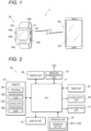
- FIG. 1 shows an information processing system 1 according to a first illustrative embodiment.
- the information processing system 1 includes an electronic timepiece 10 (electronic device) and a smart phone 20 (external device).
- the electronic timepiece 10 is a wristwatch that is worn on a user's wrist and used.
- the electronic timepiece 10 includes a body part 101 provided with a display unit 13, a first operation button 141 to a fifth operation button 145, and the like, and a belt 102 attached to the body part 101.
- the display unit 13 is configured to digitally display various types of information including a time.
- a first operation button 141 is provided on an upper side of a right side surface of the body part 101
- a second operation button 142 is provided on a lower side of the right side surface of the body part 101
- a third operation button 143 is provided on an upper side of a left side surface
- a fourth operation button 144 is provided on a lower side of the left side surface.
- a fifth operation button 145 is provided below the display unit 13 in a front surface of the body part 101.
- the electronic timepiece 10 is adapted to be able to perform data communication with the smart phone 20 by near field communication.
- BLE which is an abbreviation for Bluetooth (registered trademark) Low Energy
- the electronic timepiece 10 corresponds to a peripheral (slave device) in BLE
- the smart phone 20 corresponds to a central (master device) in BLE.
- the electronic timepiece 10 can operate in a notification mode of performing a display based on notification data ND (which is one example of notification information) (refer to FIGS. 2 and 4 ) received from the smart phone 20.
- the basic timepiece mode corresponds to "the first mode in which the display unit performs a display related to a normal operation of the own device (electronic device)".
- the notification mode corresponds to "the second mode in which the display unit performs a display based on the notification information”. The basic timepiece mode and the notification mode will be described in detail later.
- the electronic timepiece 10 can also operate in various operation modes such as a world timepiece mode for displaying a time in every corner of the world, an alarm mode for setting an alarm time, a stopwatch mode, and a timer mode, in addition to the basic timepiece mode and the notification mode
- a world timepiece mode for displaying a time in every corner of the world
- an alarm mode for setting an alarm time
- a stopwatch mode for setting an alarm time
- a timer mode in addition to the basic timepiece mode and the notification mode
- the world timepiece mode, the alarm mode, the stopwatch mode, and the timer mode may also be included in the "first mode".
- the smart phone 20 is a terminal device that is mainly carried and used by a user, and has a call function, a data communication function, and various information processing functions.
- an application program hereinafter referred to as a cooperative application 221 (refer to FIG. 4 ) for performing cooperative operations with the electronic timepiece 10 is installed.
- the smart phone 20 can set the electronic timepiece 10 (setting of an alarm time, a world time, etc.) or display stopwatch data obtained from the electronic timepiece 10 on the cooperative application 221.
- the smart phone 20 When the smart phone 20 receives an advertise packet from the electronic timepiece 10 registered (i.e., paired) in advance by exchanging a public key or the like, the smart phone starts data communication with the electronic timepiece 10 by BLE.
- An operation in which the electronic timepiece 10, which is a peripheral, transmits an advertise packet corresponds to "transmitting a communication start request for starting data communication".
- the smart phone 20, which is a central does not request communication start to the electronic timepiece 10.
- the electronic timepiece 10 may also be adapted not to accept a communication start request from the smart phone 20.
- the smart phone 20 receives device data 123 (device information) described later from the electronic timepiece 10, and transmits time data for time correction and notification data ND described above to the electronic timepiece 10. Further, during data communication for manual connection described later, the smart phone further transmits setting contents and the like set on the cooperative application 221 to the electronic timepiece 10.
- FIG. 2 is a block diagram showing a functional configuration of the electronic timepiece 10.
- the electronic timepiece 10 includes a CPU 11 (which is an abbreviation for Central Processing Unit), a memory 12 (storage unit), a display unit 13, an operation unit 14, a timer unit 15, a sound output unit 16, a light-emitting unit 17, a sensor unit 18, a wireless communication unit 19 (communication unit), and the like.
- the CPU 11 is a processor that controls an operation of each unit of the electronic timepiece 10 by reading and executing the program 121 stored in the memory 12 and performing various types of arithmetic processing.
- the CPU 11 corresponds to the "control unit".
- the electronic timepiece 10 may include a plurality of processors (for example, a plurality of CPUs), and the plurality of processors may execute a plurality of processing that is executed by the CPU 11 of the present illustrative embodiment.
- the plurality of processors correspond to the "control unit".
- the plurality of processors may be involved in common processing, or the plurality of processors may independently execute different processes in parallel.
- the memory 12 is a non-transitory recording medium that is readable by the CPU 11 as a computer.
- the memory 12 includes, for example, a non-volatile memory such as a flash memory.
- the memory 12 stores various types of data including a notification flag 122 (notification setting), device data 123, and notification data ND, in addition to the program 121.
- the program 121 is stored in the memory 12 in the form of computer-readable program codes.
- the memory 12 may include a RAM (which is an abbreviation for Random Access Memory) that is used for arithmetic processing of the CPU 11.
- the notification flag 122 is notification setting data that is referenced when determining whether to perform a transition between the basic timepiece mode and the notification mode, in notification control processing described later.
- the notification flag 122 is, for example, one-bit data.
- the device data 123 includes information related to a user's operation history on the first operation button 141 to the fifth operation button 145 of the operation unit 14, information related to a time being measured or a measured time in the stopwatch mode, and information related to a posture, an operation, a history thereof or the like of the own device by the sensor unit 18.
- the notification data ND is data that is received from the smart phone 20, and includes various types of setting information that designates an operation in the notification mode.
- the content of the notification data ND will be described later.
- the display unit 13 is a liquid crystal monitor that performs a digital display under control of the CPU 11.
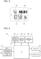
- FIG. 3 is a view showing the display unit 13 when the electronic timepiece 10 is operating in the basic timepiece mode.
- the display unit 13 includes a first segment display region 131 for displaying an hour and a minute, a second segment display region 132 for displaying a second or the like, a third segment display region 133 for displaying a day of the week, or the like, and a dot display region 134 (image display region) for displaying a date, or the like.
- the first segment display region 131 to the third segment display region 133 are so-called 7-segment type display regions, and display numbers and characters by switching between on and off states of a drive voltage for a segment electrode constituting each segment to switch between lighting and non-lighting of each segment (to switch a drive state of a liquid crystal layer).
- the dot display region 134 is here a display region having rectangular dot electrodes aligned in a matrix shape of 5 vertical rows and 17 horizontal columns.
- the dot display region 134 displays an image such as a number, a character or a figure according to arrangement of lighted dots by individually switching between on and off states of the drive electrode for each dot electrode to switch between lighting and non-lighting of each dot.
- the display unit 13 may further include display elements not shown in FIG. 3 (for example, display elements for displaying various statuses of the electronic timepiece 10, and the like).
- the operation unit 14 is an operation input device including the first operation button 141 to the fifth operation button 145 described above.
- the operation unit 14 receives user operations on the first operation button 141 to the fifth operation button 145 (for example, an operation of pressing each operation button), and outputs an operation signal corresponding to each operation button to the CPU 11.
- the CPU 11 executes processing corresponding to a function assigned to the operation button on which the user operation has been performed.
- a history of user operations on the operation unit 14 is stored in the device data 123.
- the operation unit 14 may further include other operation target members such as a crown.
- the operation unit 14 may have a touch panel provided superimposed on a display screen of the display unit 13.
- the timer unit 15 is a timer module including an oscillator circuit, a frequency divider circuit, a timer circuit, and the like.
- the frequency divider circuit frequency-divides a clock signal generated by the oscillator circuit, and the timer circuit counts the frequency-divided signal, so that current date and time are derived and held.
- the sound output unit 16 is a speaker that outputs a sound such as a beep sound in response to a control signal transmitted from the CPU 11.
- the sound output unit 16 of the present illustrative embodiment can switch between an output and a non-output of the sound in a unit of 1/16 second. Further, the sound output unit 16 may be configured to switch a frequency of the sound to be output in two or more stages.
- the light-emitting unit 17 includes a light-emitting element such as an LED (which is an abbreviation for Light Emitting Diode), and emits light in a pattern according to a control signal transmitted from the CPU 11.
- the light-emitting unit 17 may emit light in a direction of illuminating an inside of a display surface of the display unit 13 or may emit light toward the outside of the body part 101.
- the sensor unit 18 includes at least one of a 3-axis acceleration sensor, a 3-axis gyro sensor, and a 3-axis geomagnetic sensor, and detects a posture and a motion state of the own device (electronic timepiece 10).
- the sensor unit 18 includes an amplifier that amplifies analog detection signals output from the respective sensors, respectively, and an AD converter that converts the amplified analog signals into digital data and outputs the same to the CPU 11.
- the wireless communication unit 19 is a communication module having an antenna, a modulation/demodulation circuit, a signal processing circuit, and the like, and performs wireless data communication with the smart phone 20 according to the BLE standard.
- FIG. 4 is a block diagram showing a functional configuration of the smart phone 20.
- the smart phone 20 includes a CPU 21, a memory 22, a display unit 23, an operation unit 24, a wireless communication unit 25, a telephone communication unit 26, a satellite radio wave reception processing unit 27, and the like.
- the CPU 21 is a processor that controls an operation of each unit of the smart phone 20 by reading and executing various programs such as a cooperative application 221 stored in the memory 22 and performing various arithmetic processing.
- the memory 22 includes, for example, a non-volatile memory such as a flash memory.
- the memory 22 stores various types of data, such as notification data ND and identification data for identifying the paired electronic timepiece 10, in addition to various programs including the cooperative application 221.
- the display unit 23 has a display screen and performs a digital display on the display screen under control of the CPU 21.
- the display screen is a screen configured to perform a display in a dot matrix format, and is, for example, a liquid crystal display screen.
- the operation unit 24 receives a user's input operation and outputs an input signal corresponding to the input operation to the CPU 21.
- the operation unit 24 includes a touch panel provided superimposed on the display screen of the display unit 23, and detects, as an input operation, contact of a user's finger or the like by the touch panel. Further, the operation unit 24 may have a hardware button, together with the touch panel or instead of the touch panel, and may be able to accept an input operation by the hardware button.
- the wireless communication unit 25 is a communication module having an antenna, a modulation/demodulation circuit, a signal processing circuit, and the like, and performs wireless data communication according to wireless communication standards such as BLE and wireless LAN.
- the wireless communication unit 25 performs wireless data communication with the electronic timepiece 10 by BLE.
- the telephone communication unit 26 communicates with a mobile phone base station and the like, and transmits and receives voice data of telephone communication, packet data related to Internet connection, and the like.
- the satellite radio wave reception processing unit 27 is a module that receives and decodes radio waves transmitted from positioning satellites of a GNSS (which is an abbreviation for Global Positioning Satellite System) such as a GPS (which is an abbreviation for Global Positioning System) and calculates the current position and date and time.
- the satellite radio wave reception processing unit 27 calculates the current position and date and time under control of the CPU 21, and outputs a result to the CPU 21. In this way, in the smart phone 20, accurate time can be obtained by the satellite radio wave reception processing unit 27, and time data related to the time is transmitted to the electronic timepiece 10, and is used to correct time in the electronic timepiece 10.
- the electronic timepiece 10 normally operates in the basic timepiece mode in which a time, a date, a day of the week and the like are displayed. As shown in FIG. 3 , in the basic timepiece mode, an hour and a minute of time are displayed by the first segment display region 131, seconds of time are displayed by the second segment display region 132, a day of the week is displayed by the third segment display region 133, and a date is displayed by the dot display region 134.
- the displayed date and time in the basic timepiece mode reflect the date and time derived and maintained by the timer unit 15. The date and time derived by the timer unit 15 are corrected based on time data for time correction when the time data is received from the smart phone 20.
- the electronic timepiece 10 periodically performs data communication with the smart phone 20 by BLE at a predetermined timing during the day (in the present illustrative embodiment, four times every 6 hours during the day) to acquire time data for time correction, and corrects the date and time derived by the timer unit 15.
- the communication connection with the smart phone 20 automatically performed at this timing is described as "automatic connection” below.
- the communication connection between the electronic timepiece 10 and the smart phone 20 in the information processing system 1 of the present illustrative embodiment is limited to a case where it is started in response to a connection start request from the electronic timepiece 10 at the timings of the automatic connection, manual time connection, and manual connection described above. Therefore, even when information for a user is obtained or generated in the smart phone 20, push notification from the smart phone 20 to the electronic timepiece 10 cannot be performed at an arbitrary timing.
- the electronic timepiece 10 receives the notification data ND from the smart phone 20, and the electronic timepiece 10 notifies the user based on the notification data ND. This makes it possible to notify the user at the earliest possible timing, even in a communication connection mode of the present illustrative embodiment in which push notification from the smart phone 20 to the electronic timepiece 10 cannot be performed.
- the device data 123 including at least one of information related to a state of the electronic timepiece 10 and information related to an operation history is transmitted from the electronic timepiece 10 to the smart phone 20.
- notification data ND which designates a notification content and a notification mode to the user, is generated based on the received device data 123.
- the notification data ND is transmitted from the smart phone 20 to the electronic timepiece 10.
- the notification data ND for notifying the user of the usage conditions of the electronic timepiece 10 may be generated based on information related to the state and operation history of the electronic timepiece 10.
- the notification data ND for notifying information that is likely to attract the user's interest may be generated based on the information related to the state and operation history of the electronic timepiece 10.
- the device data 123 transmitted from the electronic timepiece 10 in certain data communication may be reflected in the notification data ND that is to be transmitted to the electronic timepiece 10 in next data communication.
- the transmission of the device data 123 may be omitted, and the smart phone 20 may generate the notification data ND without depending on the device data 123.
- the electronic timepiece 10 When the electronic timepiece 10 receives the notification data ND, the electronic timepiece shifts an operation mode to a notification mode in which a display based on the notification data ND is performed. In the notification mode, the electronic timepiece 10 performs an operation designated by the notification data ND.
- FIG. 5 shows contents of the notification data ND.
- the notification data ND includes notification flag information I1, image information I2, sound information 13, light emission information I4, indicator indicating position information I5 (indicating position information), and segment display information I6.
- the notification flag information I1 is one-bit data that takes any one value of "1 (on)" instructing transition to the notification mode and "0 (off)" instructing not to transition to the notification mode.
- a content of the notification flag information I1 is reflected (copied) in the notification flag 122 in the memory 12.
- the image information I2 includes data relating to an image Im (refer to FIG. 6 ) that is to be displayed in the dot display region 134 of the display unit 13 in the notification mode. Specifically, the image information I2 includes data indicating the number of dots in the vertical and horizontal directions of the image Im, and image data of the image Im (data indicating on/off of each dot).
- the sound information I3 includes data that designates an output mode of sound by the sound output unit 16 in the notification mode.
- the sound information I3 includes bit data that designates on/off of sound in a unit of 1/16 second, for example.
- the number of the bit data can be set, for example, to about 160 bits (equivalent to 10 seconds).
- the sound information I3 may contain data that designates a frequency of sound to be output.
- the light emission information I4 includes data that designates a light emission mode by the light-emitting unit 17 in the notification mode.
- the light emission information I4 may be data that designates any one of a plurality of preset light emission patterns, or may be data that directly designates on/off timings of light emission by the light-emitting unit 17.
- the indicator indicating position information I5 includes data that designates an indicating position of an indicator in the notification mode, when the electronic timepiece 10 has an indicator (e.g., a mode hand (which may also be referred to as a mode indicator) 137 (refer to FIGS. 11 and 12 )). As in the electronic timepiece 10 of the present illustrative embodiment, when no indicator is provided, the indicator indicating position information I5 is not used.
- an indicator e.g., a mode hand (which may also be referred to as a mode indicator) 137 (refer to FIGS. 11 and 12 )
- the indicator indicating position information I5 when no indicator is provided, the indicator indicating position information I5 is not used.
- the segment display information I6 includes data that designates a lighting mode of each segment in the second segment display region 132 in the notification mode.
- FIG. 6 is a view showing the display unit 13 when the electronic timepiece 10 is operating in the notification mode.
- the operation mode of the electronic timepiece 10 transitions to the notification mode.
- the image Im is displayed based on the image information I2 included in the notification data ND in the dot display region 134.
- an image Im of characters "INFO" which indicates that there is new information, is displayed in the dot display region 134.
- a size of the image Im in FIG. 6 is 5 vertical dots x 17 horizontal dots, which is the same as the size of the dot display region 134.
- the present invention is not limited thereto.
- the number of vertical dots of the image Im may be made larger than 5 dots, and the image may be scrolled in the vertical direction in the dot display region 134.
- FIG. 7 shows another example of the image Im that is displayed in the dot display region 134.
- a size of the image Im shown in FIG. 7 is 20 vertical dots x 17 horizontal dots, and an illustration of a timepiece is included at an upper portion of the image Im, and characters "NEW" are included at a lower portion.
- the image Im is displayed, for example, when notifying the user that there is a new timepiece.
- a range A of 5 dots from the top including an upper portion of the timepiece, is displayed.
- the image is switched at a predetermined frame rate such that the display range goes downward one dot by one dot in FIG. 7 , and finally, a range B of 5 dots from the bottom, including the characters "NEW", is displayed.
- the image Im is displayed so as to scroll downward from the upper end.
- the image Im that is displayed in the dot display region 134 is not limited to those illustrated in FIGS. 6 and 7 .
- the user may be notified that there is new information, an event or the like in a service by setting the image Im (image of a character, image of a sign, etc.) related to the service such as a metaverse that the user uses.
- an amount of information to be notified to the user may be increased by setting the image Im including characters spanning over a plurality of rows.
- a display is performed in the second segment display region 132 according to the segment display information I6 included in the notification data ND.
- “L9” indicating that the user's level is "9” is displayed.
- the user level may be, for example, a value related to a number of times or a frequency of obtaining the notification data ND in a certain application or a certain service of the smart phone 20.
- the value of the number of obtaining times or the obtaining frequency may be, for example, a value in one day or a value in a predetermined period.
- the content that is displayed in the second segment display region 132 may be explanation information or supplementation information related to the image Im displayed in the dot display region 134.
- the image Im indicates that there is a brand-new timepiece
- characters or numbers indicating at least a part of identification information (model number, product name, nickname, etc.) of the brand-new timepiece are displayed in the second segment display region 132.
- the display in the second segment display region 132 is not limited to the user level, and may be any information that can be expressed by a combination of two numbers or letters.
- a two-letter code that can be referenced in a reference table possessed by the user may be used, and information corresponding to the code may be grasped by the user from the reference table.
- a notification based on the notification data ND is displayed in a notification region R including the second segment display region 132 and the dot display region 134 of the display unit 13.
- the display of the hour and minute by the first segment display region 131 and the display of the day of the week by the third segment display region 133 are continuously performed.
- a part of the display in the basic timepiece mode may be continuously performed.
- the sound output unit 16 outputs a sound in an output mode corresponding to the sound information I3 in the notification mode.
- the light-emitting unit 17 emits light in a light emission mode (light emission pattern) corresponding to the light emission information I4 in the notification mode.
- the sound output unit 16 when an input operation (pressing operation) by the user is performed on the fourth operation button 144 (first operation accepting unit) in the notification mode, the sound output unit 16 outputs sound according to the sound information I3. Further, when an input operation (pressing operation) by the user is performed on the fifth operation button 145 (second operation accepting unit) in the notification mode, the light-emitting unit 17 emits light in a light emission mode according to the light emission information I4.
- a sound output control for causing the sound output unit 16 to output sound in the output mode according to the sound information I3 and a light emission control for causing the light-emitting unit 17 to emit light in the light emission mode according to the light emission information I4 may be executed so as to be alternately switched.
- the notification flag 122 is set to "1 (on)" in response to reception of the notification data ND, when any one of the first operation button 141 to the third operation button 143 is operated, the operation mode of the electronic timepiece 10 transitions to the basic timepiece mode shown in FIG. 3 . Further, when the second operation button 142 is operated in this state, the operation mode again transitions to the notification mode shown in FIG. 6 if the notification flag 122 remains "1 (on)". That is, when the notification flag 122 is "1 (on)", the user can switch the operation mode between the notification mode and the basic timepiece mode by performing a predetermined operation.
- the notification flag 122 is changed to "0 (off)" when a predetermined notification termination condition is satisfied.
- the notification termination condition in the present illustrative embodiment is satisfied when the time reaches 0:00 A.M. Therefore, after the notification flag 122 becomes “1 (on)" in response to reception of the notification data ND, if dates are crossed, the notification flag 122 is set to "0 (off)", and thereafter, the transition to the notification mode will not occur even though the second operation button 142 is operated.
- the operation mode is the notification mode at 0:00 A.M.
- the operation mode transitions from the notification mode to the basic timepiece mode, in response to the notification flag 122 being set to "0 (off)".
- the notification termination condition is not limited to one exemplified above.
- the notification termination condition may be assumed to be satisfied when a predetermined time other than 0:00 A.M. is reached, or when a predetermined operation (e.g., an operation of pressing and holding a predetermined operation button for a predetermined period of time or longer, or an operation of pressing two or more predetermined operations at the same time) is performed by the user.
- a predetermined operation e.g., an operation of pressing and holding a predetermined operation button for a predetermined period of time or longer, or an operation of pressing two or more predetermined operations at the same time
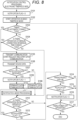
- FIG. 8 is a flowchart showing a control procedure of notification control processing that is executed by the CPU 11 of the electronic timepiece 10.
- the notification control processing is started when the electronic timepiece 10 is activated.
- the CPU 11 sets the notification flag 122 to "0" (step S101), and starts an operation of each unit in the basic timepiece mode (step S102).
- the CPU 11 determines whether it is a timing of automatic connection that is made four times in a day (step S103). If it is determined that it is not the timing of automatic connection ("NO” in step S103), the CPU determines whether an operation for the manual connection or manual time connection has been performed (step S104). If it is determined that it is the timing of automatic connection ("YES” in step S103), or if it is determined that the operation for the manual connection or manual time connection has been performed (“YES” in step S104), the CPU 11 causes the wireless communication unit 19 to transmit a communication start request (advertise packet in BLE), and to start data communication with the smart phone 20 (step S105). Note that, although not shown in FIG. 8 , in the data communication, the CPU 11 receives time data for time correction, data related to various settings made on the cooperative application 221, and the like from the smart phone 20.
- the CPU 11 transmits the device data 123 stored in the memory 12 at that time to the smart phone 20 (step S106) and resets the device data 123. Further, the CPU 11 determines whether the notification data ND has been received from the smart phone 20 within a predetermined standby period (step S107). Here, it is assumed that the notification flag information I1 of the received notification data ND is "1". If it is determined that the notification data ND has not been received within the standby period ("NO" in step S107), the CPU 11 terminates data communication with the smart phone 20 (step S108) and advances the processing to step S112.
- step S107 If it is determined that the notification data ND has been received ("YES” in step S107), the CPU 11 sets the notification flag 122 to "1" (step S109), terminates data communication with the smart phone 20 (step S110), and executes notification mode processing (step S111).
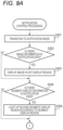
- FIGS. 9A and 9B are a flowchart showing a control procedure of notification mode processing that is executed by the CPU 11 of the electronic timepiece 10.
- the CPU 11 shifts the operation mode of the electronic timepiece 10 to the notification mode (step S201), and starts processing of step S202 and subsequent steps relating to the notification mode.
- the CPU 11 determines whether the image information I2 is included in the received notification data ND (step S202). If it is determined that the image information I2 is included ("YES" in step S202), the CPU causes the image Im to be displayed in the dot display region 134 according to the image information I2 (step S203). Here, when the number of vertical dots of the image Im is larger than the number of vertical dots of the dot display region 134, the CPU 11 scrolls the image Im by the method described above.
- step S203 When the processing of step S203 terminates, or if it is determined that the notification flag information I1 is not included in the notification data ND ("NO" in step S202), the CPU 11 determines whether the segment display information I6 is included in the notification data ND (step S204). If it is determined that the segment display information I6 is included (“YES” in step S204), the CPU 11 lights up segments in the second segment display region 132 according to the segment display information I6 for display (step S205).
- step S205 determines whether an operation on the fourth operation button 144 has been performed (step S206). If it is determined that an operation on the fourth operation button 144 has been performed ("YES” in step S206) and the sound information I3 is included in the notification data ND ("YES” in step S207), the CPU 11 causes the sound output unit 16 to output sound in the output mode corresponding to the sound information I3 (step S208). In addition, in parallel with the sound output by the sound output unit 16, the CPU may scroll once the image Im in the dot display region 134.
- step S208 terminates, or if it is determined in step S207 that the sound information I3 is not included in the notification data ND ("NO” in step S207), the CPU 11 advances the processing to step S212.
- step S206 determines whether an operation on the fifth operation button 145 has been performed (step S209). If it is determined that an operation on the fifth operation button 145 has been performed ("YES” in step S209) and the light emission information I4 is included in the notification data ND ("YES” in step S210), the CPU 11 causes the light-emitting unit 17 to emit light in the light emission mode corresponding to the light emission information I4 (step S211). In addition, in parallel with the light emission by the light-emitting unit 17, the CPU may scroll once the image Im in the dot display region 134.
- step S211 When the processing of step S211 terminates, if it is determined in step S209 that no operation has been performed on the fifth operation button 145 ("NO" in step S209), or if it is determined in step S210 that the light emission information I4 is not included in the notification data ND ("NO" in step S210), the CPU 11 advances the processing to step S212.
- step S209 may be omitted, and step S207 and step S210 may be alternately executed each time it is determined in step S206 that the fourth operation button 144 has been operated.
- step S212 the CPU 11 determines whether an operation on any one of the first operation button 141 to the third operation button 143 has been performed. If it is determined that the operation has not been performed ("NO" in step S212), the CPU determines whether the time measured by the timer unit 15 has passed 0:00 A.M. (step S213). If it is determined that the time has passed 0:00 A.M. ("YES” in step S213), the CPU 11 determines that the notification termination condition of the notification mode is satisfied, and sets the notification flag 122 to "0" (step S214). If it is determined that the time has not passed 0:00 A.M. ("NO" in step S213), the CPU 11 returns the processing to step S206, and again accepts the user operations for instructing the sound output by the sound output unit 16 and the light emission by the light-emitting unit 17.
- step S214 When the processing of step S214 is executed, or if it is determined in step S212 that an operation on any one of the first operation button 141 to the third operation button 143 has been performed ("YES" in step S212), the CPU 11 shifts the operation mode of the electronic timepiece 10 to the basic timepiece mode (step S215). That is, as shown in FIG. 3 , the display in the dot display region 134 is switched to the display of the date, and the display in the second segment display region 132 is switched to the display of the seconds of the current time.
- step S215 terminates, the CPU 11 terminates the notification mode processing and returns the processing to the notification control processing in FIG. 8 .
- step S108 when the processing of step S108 or the notification mode processing of step S111 terminates, or if it is determined in step S104 that no operation for the manual connection and manual time connection has been performed ("NO” in step S104), the CPU 11 determines whether an operation on the second operation button 142 has been performed (step S112). If it is determined that an operation on the second operation button 142 has been performed ("YES” in step S112) and the notification flag 122 is "1" (“YES” in step S113), the CPU 11 returns the processing to S111, and executes the notification mode processing.
- step S112 determines whether an operation on the second operation button 142 has been performed ("YES” in step S112) and the notification flag 122 is "0" ("NO” in step S113).
- step S114 determines whether the time measured by the timer unit 15 has passed 0:00 A.M.
- step S114 determines that the time has passed 0:00 A.M. ("YES” in step S114) and the notification flag 122 is "1" (“YES” in step S115).
- step S116 determines that the notification termination condition of the notification mode is satisfied, and sets the notification flag 122 to "0" (step S116).
- step S116 sets the notification flag 122 to "0" (step S116).
- step S117 the CPU 11 advances the processing to step S117.
- the CPU 11 advances the processing to step S117 without changing the notification flag 122.
- step S117 the CPU 11 determines whether an operation for turning off the power of the electronic timepiece 10 has been performed.
- the CPU 11 returns the processing to step S103 if it is determined that the above operation has not been performed ("NO” in step S117), and terminates the notification control processing if it is determined that the above operation has been performed ("YES" in step S117).
- step S107 it is assumed that the notification flag information I1 of the notification data ND received in step S107 is "1". However, if the notification flag information I1 of the received notification data ND is "0", the processing may be advanced to step S116 to set the notification flag 122 to "0".
- FIG. 10 is a flowchart showing a control procedure of notification control processing that is executed by the CPU 21 of the smart phone 20.
- the notification control processing is started when the smart phone 20 is activated.
- the CPU 21 determines whether a communication start request has been made from the electronic timepiece 10 (whether the BLE advertise packet has been transmitted) (step S301). If it is determined that a communication start request has been made (if an advertise packet is received), the CPU 21 starts data communication with the electronic timepiece 10 (step S302).
- the CPU 21 receives the device data 123 from the electronic timepiece 10 in the started data communication (step S303), and generates the notification data ND based on the device data 123 (step S304).
- the notification data ND may be generated without being based on the device data 123 as described above. Further, in this case, the CPU 21 may generate the notification data ND in advance (for example, in a stage in which the CPU 21 acquires notification-related information) before data communication starts in step S302.
- the CPU 21 transmits the generated notification data ND to the electronic timepiece 10 (step S305). Note that, although not shown in FIG. 10 , in the data communication, time data for time correction, data related to various settings made on the cooperative application 221, and the like are also transmitted to the electronic timepiece 10.
- the CPU 21 After transmitting the notification data ND, the CPU 21 terminates data communication with the electronic timepiece 10 (step S306).
- the CPU 21 determines whether an operation for turning off the power of the smart phone 20 has been performed (step S307).
- the CPU 21 returns the processing to step S301 if it is determined that the above operation has not been performed ("NO” in step S307), and terminates the notification control processing if it is determined that the above operation has been performed ("YES" in step S307).
- the electronic timepiece 10 includes the wireless communication unit 19, the display unit 13, and the CPU 11.
- the wireless communication unit 19 transmits a communication start request for starting data communication with the smart phone 20 to the smart phone 20, and performs data communication.
- the CPU 11 causes the wireless communication unit 19 to transmit a communication start request to the smart phone 20 and to start data communication with the smart phone 20 (step S105 in FIG. 8 ).
- the CPU 11 shifts the operation mode of the own device from the basic timepiece mode in which the display unit 13 displays a normal operation of the own device to the notification mode in which the display unit 13 performs a display based on the notification data ND (step S111, and step S201 in FIG. 9A ).
- step S111, and step S201 in FIG. 9A As a result, even in a mode of communication connection in which push notification from the smart phone 20 to the electronic timepiece 10 cannot be performed, when information for the user is obtained or generated in the smart phone 20, notification to the user can be performed via the electronic timepiece 10 at the earliest possible timing.
- the user can recognize that there is information for the user by checking the electronic timepiece 10 that has automatically transitioned to the notification mode, without checking the smart phone 20.
- the user who has checked the notification on the electronic timepiece 10 can timely access more detailed information on an application or the like on the smart phone 20. In this way, according to the configuration of the above illustrative embodiment, user convenience regarding access to information can be enhanced.
- the CPU 11 switches the operation mode of the own device from the notification mode to the basic timepiece mode (step S215). This makes it possible not to continue the notification mode when there is no new information for the user. Therefore, when there is new information for the user, notification in the notification mode can be made in a timely manner.
- the electronic timepiece 10 includes the memory 12 in which the notification flag 122 related to the presence or absence of notification by the notification data ND is stored.
- the CPU 11 sets the notification flag 122 to ON (step S109 in FIG. 8 ).
- the CPU sets the notification flag 122 to OFF (step S116 in FIG. 8 or step S214 in FIG. 9B ).
- the CPU switches the operation mode of the own device between the notification mode and the basic timepiece mode, in response to a predetermined user operation (steps S111 to S113 in FIG. 8 and steps S201, S212 and S215 in FIGS. 9A and 9B ).
- the notification flag 122 is OFF, the CPU does not perform the transition to the notification mode corresponding to the user operation.
- the user can switch and check information such as notification in the notification mode and time in the basic timepiece mode at a desired timing.
- the electronic timepiece 10 includes the timer unit 15 that measures a time, and when the time measured by the timer unit 15 reaches a predetermined time ("YES" in step S114 of FIG. 8 , or "YES” in step S213 of FIG. 9B ), the CPU 11 determines that the notification termination condition is satisfied.
- a predetermined time "YES" in step S114 of FIG. 8 , or "YES” in step S213 of FIG. 9B .
- the display unit 13 has the dot display region 134 configured to display an image, and when the image information I2 related to an image is included in the obtained notification data ND, the CPU 11 causes the image Im based on the image information I2 to be displayed in the dot display region 134 of the display unit 13 in the notification mode (steps S202 and S203 in FIG. 9A ). This allows for visually easy-to-understand notification using the image Im.
- the electronic timepiece 10 includes the sound output unit 16, and when the sound information I3 related to the sound output mode is included in the obtained notification data ND, the CPU 11 causes the sound output unit 16 to output sound in an output mode corresponding to the sound information I3 in the notification mode (steps S207 and S208 in FIG. 9B ). This enables notification by sound of various output modes corresponding to the sound information I3, together with the display by the display unit 13.
- the electronic timepiece 10 includes the light-emitting unit 17, and when the light emission information I4 related to the light emission mode is included in the obtained notification data ND, the CPU 11 causes the light-emitting unit 17 to emit light in a light emission mode corresponding to the light emission information I4 in the notification mode (steps S209 and S210 in FIG. 9B ). This enables notification by light emission of various light emission modes corresponding to the light emission information I4, together with the display by the display unit 13.
- the electronic timepiece 10 includes the fourth operation button 144 and the fifth operation button 145 that are input operation targets by the user.
- the CPU 11 causes the sound output unit 16 to output sound in an output mode according to the sound information I3 (step S208), and when the light emission information I4 is included in the obtained notification data ND and an input operation has been performed on the fifth operation button 145 in the notification mode ("YES" in step S209), the CPU causes the light-emitting unit 17 to emit light in a light emission mode according to the light emission information I4 (step S211).
- the user can cause the sound output unit 16 to output sound and the light-emitting unit 17 to emit light at a desired timing.
- the CPU 11 may alternately switch and execute the sound output control (step S208 in FIG. 9B ) for causing the sound output unit 16 to output sound in an output mode according to the sound information I3 and the light emission control (step S211) for causing the light-emitting unit 17 to emit light in a light emission mode according to the light emission information I4 each time an input operation is performed on the fourth operation button 144 in the notification mode.
- the user can cause the sound output unit 16 to output sound and the light-emitting unit 17 to emit light at a desired timing by using one operation button.
- the CPU 11 transmits the device data 123, which includes at least one of the information related to the state of the own device and the information related to the operation history of the own device, to the smart phone 20, and acquires the notification data ND generated based on the device data 123 from the smart phone 20. This allows for notification in which the state and operation history of the own device are reflected.
- the CPU 11 causes the number of obtaining times or obtaining frequency of the notification data ND to be displayed in the second segment display region 132 of the display unit 13 in the notification mode. This allows for various notifications in which the user's usage conditions and the like of the electronic timepiece 10 are reflected.
- the electronic timepiece 10 corresponds to a peripheral. This makes it possible to start data communication with the smart phone 20 by transmitting an advertise packet from the electronic timepiece 10 (transmitting a communication start request).
- control method of the electronic timepiece 10 causes the wireless communication unit 19 to transmit a communication start request to the smart phone 20 and to start data communication with the smart phone 20.
- the control method shifts the operation mode of the electronic device from the basic timepiece mode in which the display unit 13 displays a normal operation of the electronic device to the notification mode in which the display unit 13 performs a display based on the notification data ND.
- the program 121 causes the CPU 11 as a computer provided in the electronic timepiece 10 to execute processing of causing the wireless communication unit 19 to transmit a communication start request to the smart phone 20 and to start data communication with the smart phone 20, and processing of, when the notification data ND is obtained from the smart phone 20 in the started data communication, shifting the operation mode of the electronic device from the basic timepiece mode in which the display unit 13 displays a normal operation of the electronic device to the notification mode in which the display unit 13 performs a display based on the notification data ND.
- the information processing system 1 of the second illustrative embodiment is different from the first illustrative embodiment in that the display unit 13 of the electronic timepiece 10 can display a combination of a digital display and an analog display based on an indicator.
- the display unit 13 of the electronic timepiece 10 can display a combination of a digital display and an analog display based on an indicator.
- FIG. 11 shows the display unit 13 of the electronic timepiece 10 according to the second illustrative embodiment.
- FIG. 11 shows the display unit 13 when the electronic timepiece is operating in the basic timepiece mode.
- the display unit 13 of the electronic timepiece 10 of the present illustrative embodiment includes a minute hand 135, an hour hand 136, and a mode hand 137 for displaying information such as time in an analog manner, and a first segment display region 131, a second segment display region 132, and a dot display region 134 for displaying information such as a date and a day of the week in a digital manner.
- the first segment display region 131 of the present illustrative embodiment displays a date.
- a content that is displayed by at least one of the first segment display region 131, the second segment display region 132, and the dot display region 134 may be changed by operating a predetermined operation button. For example, each time the second operation button 142 is operated, the display content by the first segment display region 131 may be switched between a date and an hour and minute.
- the mode hand 137 is an indicator configured to indicate any one of a plurality of different indicating positions, and is an indicator that displays an operation mode of the electronic timepiece 10.
- the mode hand 137 indicates an indicating position "BT"
- it represents that an operation mode is a basic timepiece mode
- the mode hand 137 indicates an indicating position of "AL” it represents that an operation mode is an alarm mode
- the mode hand 137 indicates an indicating position "ST” it represents that an operation mode is a stopwatch mode
- the mode hand 137 indicates an indicating position "INFO”
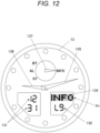
- FIG. 12 is a view showing the display unit 13 when the electronic timepiece 10 according to the second illustrative embodiment is operating in the notification mode.
- the image Im is displayed in the dot display region 134 and the user level is displayed in the second segment display region 132.
- the indicating position of the mode hand 137 is changed to "INFO".
- the notification mode is indicated by the mode hand 137, and the content based on the notification data ND is displayed in the dot display region 134 and the second segment display region 132.
- the sound output by the sound output unit 16 and/or the light emission by the light-emitting unit 17 may be performed.
- the electronic timepiece 10 that performs a combination of a digital display and an analog display has been exemplified.
- the present invention is not limited thereto.
- a configuration is also possible in which only an analog display by an indicator is performed.
- one or two or more indicators indicate the indicating position corresponding to the content of the notification data ND, so that necessary notification can be made to the user.
- the display unit 13 has the mode hand 137 configured to indicate any one of a plurality of different indicating positions.
- the CPU 11 causes the mode hand 137 of the display unit 13 to indicate an indicating position corresponding to the indicator indicating position information I5 among the plurality of indicating positions in the notification mode.
- the electronic timepiece 10 has been exemplified as an electronic device, the present invention is not limited thereto.
- the electronic device may be a clock set up and used on a desk or a wall, or may be various devices other than a timepiece (for example, a wearable device worn on the body and used).
- the external device is not limited to the smart phone 20, and may be a tablet-type terminal, a laptop computer, a stationary type PC, or the like.
- the digital display unit 13 has been exemplified as being configured by the 7-segment type display region or dot display region, the display unit is not limited thereto and may have a display region of an active matrix type. In this case, in the notification mode, detailed information corresponding to the resolution of the display region of the active matrix type may be displayed.
- At least one of the sound output by the sound output unit 16 and the light emission by the light-emitting unit 17 may not be performed.
- the sound output unit 16 can be omitted, and the sound information I3 can be omitted in the notification data ND.
- the light-emitting unit 17 when the light emission by the light-emitting unit 17 is not performed, the light-emitting unit 17 can be omitted, and the light emission information I4 can be omitted in the notification data ND.
- the electronic timepiece 10 corresponds to a peripheral (slave device), and the smart phone 20 corresponds to a central (master device), but the present invention is not limited thereto.
- the electronic timepiece 10 may correspond to a central (master device) and the smart phone 20 may correspond to a peripheral (slave device).
- the reception of the communication start request from the smart phone 20 may trigger the start of communication processing by the wireless communication unit 19.
- the present invention is not limited to this example.
- information recording media such as HDD (which is an abbreviation for Hard Disk Drive), SSD (which is an abbreviation for Solid State Drive) and CD-ROM (which is an abbreviation for Compact Disc Read Only Memory) can be applied.
- a carrier wave is also applied to the present invention.
Landscapes
- Engineering & Computer Science (AREA)
- Physics & Mathematics (AREA)
- Theoretical Computer Science (AREA)
- General Physics & Mathematics (AREA)
- General Engineering & Computer Science (AREA)
- Computer Hardware Design (AREA)
- Human Computer Interaction (AREA)
- Acoustics & Sound (AREA)
- Signal Processing (AREA)
- Mathematical Physics (AREA)
- Power Engineering (AREA)
- Electric Clocks (AREA)
- Telephone Function (AREA)
- Electromechanical Clocks (AREA)
Abstract
Description
- The present invention relates to an electronic device, a control method of an electronic device, and a program.
- In recent years, even in small electronic devices such as wristwatches, a technology for acquiring necessary information through data communication with an external device and reflecting the information in operations has been used. In such an electronic device, it is required to suppress power consumption to a low level so that a continuous operation for a long time can be performed with a battery having a small capacity (for example, a button-type battery). In particular, since data communication with an external device consumes a large amount of power, it is necessary to suppress the communication frequency and communication time. For example, in
JP2008-39396A - However, if the timing of data communication is restricted as described above, push notification cannot be performed from the external device to the electronic device. For this reason, even if information for a user is obtained or generated in the external device, the user cannot check the presence or absence of the information or the content of the information with the electronic device. Thus, the technology of the related art has a problem in that user convenience regarding access to information is low.
- Illustrative aspects of the present invention provide an electronic device, a control method of an electronic device, and a program that enhance user convenience regarding access to information.
- One illustrative aspect of the present invention provides an electronic device including: a communication unit configured to transmit a communication start request to an external device and to perform data communication with the external device, the communication start request being for starting the data communication with the external device having a battery capacity greater than that of the electronic device; a display unit; and a control unit. The control unit is configured to: control the communication unit to transmit the communication start request to the external device and to start the data communication with the external device; and based on obtaining notification information from the external device in the started data communication, shift an operation mode of the electronic device from a first mode to a second mode, the display unit displaying a normal operation of the electronic device in the first mode, the display unit performing a display based on the notification information in the second mode.
- Another illustrative aspect of the present invention provides a control method of an electronic device, the electronic device including a display unit and a communication unit configured to transmit a communication start request to an external device and to perform data communication with the external device, the communication start request being for starting data communication with the external device having a battery capacity greater than that of the electronic device. The control method includes: controlling the communication unit to transmit the communication start request to the external device and to start the data communication with the external device; and based on obtaining notification information from the external device in the started data communication, shifting an operation mode of the electronic device from a first mode to a second mode, the display unit displaying a normal operation of the electronic device in the first mode, the display unit performing a display based on the notification information in the second mode.
- Still another illustrative aspect of the present invention provides a program executable on a computer of an electronic device, the electronic device including a display unit and a communication unit configured to transmit a communication start request to an external device and to perform data communication with the external device, the communication start request being for starting data communication with the external device having a battery capacity greater than that of the electronic device to the external device. The program, when executed by the computer, causes the computer to perform: controlling the communication unit to transmit the communication start request to the external device and to start the data communication with the external device; and based on obtaining notification information from the external device in the started data communication, shifting an operation mode of the electronic device from a first mode to a second mode, the display unit displaying a normal operation of the electronic device in the first mode, the display unit performing a display based on the notification information in the second mode.
-
-
FIG. 1 shows an information processing system according to a first illustrative embodiment. -
FIG. 2 is a block diagram showing a functional configuration of an electronic timepiece. -
FIG. 3 is a view showing a display unit when the electronic timepiece is operating in a basic timepiece mode. -
FIG. 4 is a block diagram showing a functional configuration of a smart phone. -
FIG. 5 shows contents of notification data. -
FIG. 6 is a view showing the display unit when the electronic timepiece is operating in a notification mode. -
FIG. 7 shows another example of an image that is displayed in a dot display region. -
FIG. 8 is a flowchart showing a control procedure of notification control processing that is executed by a CPU of the electronic timepiece. -
FIGS. 9A and9B are a flowchart showing a control procedure of notification mode processing that is executed by the CPU of the electronic timepiece. -
FIG. 10 is a flowchart showing a control procedure of notification control processing that is executed by a CPU of a smart phone. -
FIG. 11 is a view showing a display unit of an electronic timepiece according to a second illustrative embodiment. -
FIG. 12 is a view showing the display unit when the electronic timepiece according to the second illustrative embodiment is operating in the notification mode. - Hereinafter, illustrative embodiments of the present invention will be described with reference to the drawings.
-
FIG. 1 shows aninformation processing system 1 according to a first illustrative embodiment. - The
information processing system 1 includes an electronic timepiece 10 (electronic device) and a smart phone 20 (external device). - The
electronic timepiece 10 is a wristwatch that is worn on a user's wrist and used. Theelectronic timepiece 10 includes abody part 101 provided with adisplay unit 13, afirst operation button 141 to afifth operation button 145, and the like, and abelt 102 attached to thebody part 101. In the present illustrative embodiment, thedisplay unit 13 is configured to digitally display various types of information including a time. When thedisplay unit 13 of thebody part 101 is viewed from the front, afirst operation button 141 is provided on an upper side of a right side surface of thebody part 101, asecond operation button 142 is provided on a lower side of the right side surface of thebody part 101, athird operation button 143 is provided on an upper side of a left side surface, and afourth operation button 144 is provided on a lower side of the left side surface. In addition, afifth operation button 145 is provided below thedisplay unit 13 in a front surface of thebody part 101. - The
electronic timepiece 10 is adapted to be able to perform data communication with thesmart phone 20 by near field communication. In the present illustrative embodiment, BLE (which is an abbreviation for Bluetooth (registered trademark) Low Energy) is used as near field communication, but the standard of near field communication to be used is not limited thereto. Theelectronic timepiece 10 corresponds to a peripheral (slave device) in BLE, and thesmart phone 20 corresponds to a central (master device) in BLE. - In addition to a basic timepiece mode of displaying a time, a date, a day of the week, and the like, the
electronic timepiece 10 can operate in a notification mode of performing a display based on notification data ND (which is one example of notification information) (refer toFIGS. 2 and4 ) received from thesmart phone 20. The basic timepiece mode corresponds to "the first mode in which the display unit performs a display related to a normal operation of the own device (electronic device)". In addition, the notification mode corresponds to "the second mode in which the display unit performs a display based on the notification information". The basic timepiece mode and the notification mode will be described in detail later. Note that theelectronic timepiece 10 can also operate in various operation modes such as a world timepiece mode for displaying a time in every corner of the world, an alarm mode for setting an alarm time, a stopwatch mode, and a timer mode, in addition to the basic timepiece mode and the notification mode The world timepiece mode, the alarm mode, the stopwatch mode, and the timer mode may also be included in the "first mode". - The
smart phone 20 is a terminal device that is mainly carried and used by a user, and has a call function, a data communication function, and various information processing functions. In thesmart phone 20, an application program (hereinafter referred to as a cooperative application 221 (refer toFIG. 4 )) for performing cooperative operations with theelectronic timepiece 10 is installed. Thesmart phone 20 can set the electronic timepiece 10 (setting of an alarm time, a world time, etc.) or display stopwatch data obtained from theelectronic timepiece 10 on thecooperative application 221. - When the
smart phone 20 receives an advertise packet from theelectronic timepiece 10 registered (i.e., paired) in advance by exchanging a public key or the like, the smart phone starts data communication with theelectronic timepiece 10 by BLE. An operation in which theelectronic timepiece 10, which is a peripheral, transmits an advertise packet corresponds to "transmitting a communication start request for starting data communication". On the other hand, thesmart phone 20, which is a central, does not request communication start to theelectronic timepiece 10. Note that theelectronic timepiece 10 may also be adapted not to accept a communication start request from thesmart phone 20. - In data communication with the
electronic timepiece 10, thesmart phone 20 receives device data 123 (device information) described later from theelectronic timepiece 10, and transmits time data for time correction and notification data ND described above to theelectronic timepiece 10. Further, during data communication for manual connection described later, the smart phone further transmits setting contents and the like set on thecooperative application 221 to theelectronic timepiece 10. -
FIG. 2 is a block diagram showing a functional configuration of theelectronic timepiece 10. - The
electronic timepiece 10 includes a CPU 11 (which is an abbreviation for Central Processing Unit), a memory 12 (storage unit), adisplay unit 13, anoperation unit 14, atimer unit 15, asound output unit 16, a light-emitting unit 17, asensor unit 18, a wireless communication unit 19 (communication unit), and the like. - The
CPU 11 is a processor that controls an operation of each unit of theelectronic timepiece 10 by reading and executing theprogram 121 stored in thememory 12 and performing various types of arithmetic processing. In the present illustrative embodiment, theCPU 11 corresponds to the "control unit". Note that theelectronic timepiece 10 may include a plurality of processors (for example, a plurality of CPUs), and the plurality of processors may execute a plurality of processing that is executed by theCPU 11 of the present illustrative embodiment. In this case, the plurality of processors correspond to the "control unit". In this case, the plurality of processors may be involved in common processing, or the plurality of processors may independently execute different processes in parallel. - The
memory 12 is a non-transitory recording medium that is readable by theCPU 11 as a computer. Thememory 12 includes, for example, a non-volatile memory such as a flash memory. Thememory 12 stores various types of data including a notification flag 122 (notification setting),device data 123, and notification data ND, in addition to theprogram 121. Theprogram 121 is stored in thememory 12 in the form of computer-readable program codes. Thememory 12 may include a RAM (which is an abbreviation for Random Access Memory) that is used for arithmetic processing of theCPU 11. - The
notification flag 122 is notification setting data that is referenced when determining whether to perform a transition between the basic timepiece mode and the notification mode, in notification control processing described later. Thenotification flag 122 is, for example, one-bit data. - The
device data 123 includes information related to a user's operation history on thefirst operation button 141 to thefifth operation button 145 of theoperation unit 14, information related to a time being measured or a measured time in the stopwatch mode, and information related to a posture, an operation, a history thereof or the like of the own device by thesensor unit 18. - The notification data ND is data that is received from the
smart phone 20, and includes various types of setting information that designates an operation in the notification mode. The content of the notification data ND will be described later. - The
display unit 13 is a liquid crystal monitor that performs a digital display under control of theCPU 11. -
FIG. 3 is a view showing thedisplay unit 13 when theelectronic timepiece 10 is operating in the basic timepiece mode. - As shown in
FIG. 3 , thedisplay unit 13 includes a firstsegment display region 131 for displaying an hour and a minute, a secondsegment display region 132 for displaying a second or the like, a thirdsegment display region 133 for displaying a day of the week, or the like, and a dot display region 134 (image display region) for displaying a date, or the like. - The first
segment display region 131 to the thirdsegment display region 133 are so-called 7-segment type display regions, and display numbers and characters by switching between on and off states of a drive voltage for a segment electrode constituting each segment to switch between lighting and non-lighting of each segment (to switch a drive state of a liquid crystal layer). - The
dot display region 134 is here a display region having rectangular dot electrodes aligned in a matrix shape of 5 vertical rows and 17 horizontal columns. Thedot display region 134 displays an image such as a number, a character or a figure according to arrangement of lighted dots by individually switching between on and off states of the drive electrode for each dot electrode to switch between lighting and non-lighting of each dot. - Note that the
display unit 13 may further include display elements not shown inFIG. 3 (for example, display elements for displaying various statuses of theelectronic timepiece 10, and the like). - The
operation unit 14 is an operation input device including thefirst operation button 141 to thefifth operation button 145 described above. Theoperation unit 14 receives user operations on thefirst operation button 141 to the fifth operation button 145 (for example, an operation of pressing each operation button), and outputs an operation signal corresponding to each operation button to theCPU 11. In response to the operation signal, theCPU 11 executes processing corresponding to a function assigned to the operation button on which the user operation has been performed. A history of user operations on theoperation unit 14 is stored in thedevice data 123. - Note that the
operation unit 14 may further include other operation target members such as a crown. In addition, theoperation unit 14 may have a touch panel provided superimposed on a display screen of thedisplay unit 13. - The
timer unit 15 is a timer module including an oscillator circuit, a frequency divider circuit, a timer circuit, and the like. In thetimer unit 15, the frequency divider circuit frequency-divides a clock signal generated by the oscillator circuit, and the timer circuit counts the frequency-divided signal, so that current date and time are derived and held. - The
sound output unit 16 is a speaker that outputs a sound such as a beep sound in response to a control signal transmitted from theCPU 11. Thesound output unit 16 of the present illustrative embodiment can switch between an output and a non-output of the sound in a unit of 1/16 second. Further, thesound output unit 16 may be configured to switch a frequency of the sound to be output in two or more stages. - The light-emitting
unit 17 includes a light-emitting element such as an LED (which is an abbreviation for Light Emitting Diode), and emits light in a pattern according to a control signal transmitted from theCPU 11. The light-emittingunit 17 may emit light in a direction of illuminating an inside of a display surface of thedisplay unit 13 or may emit light toward the outside of thebody part 101. - The
sensor unit 18 includes at least one of a 3-axis acceleration sensor, a 3-axis gyro sensor, and a 3-axis geomagnetic sensor, and detects a posture and a motion state of the own device (electronic timepiece 10). Thesensor unit 18 includes an amplifier that amplifies analog detection signals output from the respective sensors, respectively, and an AD converter that converts the amplified analog signals into digital data and outputs the same to theCPU 11. - The
wireless communication unit 19 is a communication module having an antenna, a modulation/demodulation circuit, a signal processing circuit, and the like, and performs wireless data communication with thesmart phone 20 according to the BLE standard. -
FIG. 4 is a block diagram showing a functional configuration of thesmart phone 20. - The
smart phone 20 includes aCPU 21, amemory 22, adisplay unit 23, anoperation unit 24, awireless communication unit 25, atelephone communication unit 26, a satellite radio wavereception processing unit 27, and the like. - The
CPU 21 is a processor that controls an operation of each unit of thesmart phone 20 by reading and executing various programs such as acooperative application 221 stored in thememory 22 and performing various arithmetic processing. - The
memory 22 includes, for example, a non-volatile memory such as a flash memory. Thememory 22 stores various types of data, such as notification data ND and identification data for identifying the pairedelectronic timepiece 10, in addition to various programs including thecooperative application 221. - The
display unit 23 has a display screen and performs a digital display on the display screen under control of theCPU 21. Here, the display screen is a screen configured to perform a display in a dot matrix format, and is, for example, a liquid crystal display screen. - The
operation unit 24 receives a user's input operation and outputs an input signal corresponding to the input operation to theCPU 21. Theoperation unit 24 includes a touch panel provided superimposed on the display screen of thedisplay unit 23, and detects, as an input operation, contact of a user's finger or the like by the touch panel. Further, theoperation unit 24 may have a hardware button, together with the touch panel or instead of the touch panel, and may be able to accept an input operation by the hardware button. - The
wireless communication unit 25 is a communication module having an antenna, a modulation/demodulation circuit, a signal processing circuit, and the like, and performs wireless data communication according to wireless communication standards such as BLE and wireless LAN. For example, thewireless communication unit 25 performs wireless data communication with theelectronic timepiece 10 by BLE. - The
telephone communication unit 26 communicates with a mobile phone base station and the like, and transmits and receives voice data of telephone communication, packet data related to Internet connection, and the like. - The satellite radio wave
reception processing unit 27 is a module that receives and decodes radio waves transmitted from positioning satellites of a GNSS (which is an abbreviation for Global Positioning Satellite System) such as a GPS (which is an abbreviation for Global Positioning System) and calculates the current position and date and time. The satellite radio wavereception processing unit 27 calculates the current position and date and time under control of theCPU 21, and outputs a result to theCPU 21. In this way, in thesmart phone 20, accurate time can be obtained by the satellite radio wavereception processing unit 27, and time data related to the time is transmitted to theelectronic timepiece 10, and is used to correct time in theelectronic timepiece 10. - Next, an operation of the
information processing system 1 will be described. - The
electronic timepiece 10 normally operates in the basic timepiece mode in which a time, a date, a day of the week and the like are displayed. As shown inFIG. 3 , in the basic timepiece mode, an hour and a minute of time are displayed by the firstsegment display region 131, seconds of time are displayed by the secondsegment display region 132, a day of the week is displayed by the thirdsegment display region 133, and a date is displayed by thedot display region 134. The displayed date and time in the basic timepiece mode reflect the date and time derived and maintained by thetimer unit 15. The date and time derived by thetimer unit 15 are corrected based on time data for time correction when the time data is received from thesmart phone 20. - The
electronic timepiece 10 periodically performs data communication with thesmart phone 20 by BLE at a predetermined timing during the day (in the present illustrative embodiment, four times every 6 hours during the day) to acquire time data for time correction, and corrects the date and time derived by thetimer unit 15. The communication connection with thesmart phone 20 automatically performed at this timing is described as "automatic connection" below. - In addition, even when a predetermined user operation (for example, an operation of pressing the first operation button 141) for instructing time correction is performed, data communication with the
smart phone 20 is started by BLE, in response to the user operation, and time data for time correction is obtained. In the below, the communication connection with thesmart phone 20 performed in response to a user operation for instructing time correction is described as "manual time connection". - In addition, when predetermined another user operation (for example, an operation of pressing and holding the
third operation button 143 for 3 seconds or longer) is performed, in addition to the time data for time correction, data related to various settings performed on thecooperative application 221 of thesmart phone 20 is obtained and reflected in the operation settings and the like of theelectronic timepiece 10. In the below, the communication connection with thesmart phone 20 performed in response to a user operation for acquiring data related to thecooperative application 221 from thesmart phone 20 in this way is described as "manual connection". - The communication connection between the
electronic timepiece 10 and thesmart phone 20 in theinformation processing system 1 of the present illustrative embodiment is limited to a case where it is started in response to a connection start request from theelectronic timepiece 10 at the timings of the automatic connection, manual time connection, and manual connection described above. Therefore, even when information for a user is obtained or generated in thesmart phone 20, push notification from thesmart phone 20 to theelectronic timepiece 10 cannot be performed at an arbitrary timing. - Therefore, in the
information processing system 1 of the present illustrative embodiment, in each of the automatic connection, manual time connection, and manual connection described above, theelectronic timepiece 10 receives the notification data ND from thesmart phone 20, and theelectronic timepiece 10 notifies the user based on the notification data ND. This makes it possible to notify the user at the earliest possible timing, even in a communication connection mode of the present illustrative embodiment in which push notification from thesmart phone 20 to theelectronic timepiece 10 cannot be performed. - Specifically, in each of the automatic connection, manual time connection and manual connection described above, first, the
device data 123 including at least one of information related to a state of theelectronic timepiece 10 and information related to an operation history is transmitted from theelectronic timepiece 10 to thesmart phone 20. In addition, in thesmart phone 20, notification data ND, which designates a notification content and a notification mode to the user, is generated based on the receiveddevice data 123. Then, the notification data ND is transmitted from thesmart phone 20 to theelectronic timepiece 10. For example, the notification data ND for notifying the user of the usage conditions of theelectronic timepiece 10 may be generated based on information related to the state and operation history of theelectronic timepiece 10. In addition, the notification data ND for notifying information that is likely to attract the user's interest may be generated based on the information related to the state and operation history of theelectronic timepiece 10. - Note that the
device data 123 transmitted from theelectronic timepiece 10 in certain data communication may be reflected in the notification data ND that is to be transmitted to theelectronic timepiece 10 in next data communication. In addition, the transmission of thedevice data 123 may be omitted, and thesmart phone 20 may generate the notification data ND without depending on thedevice data 123. - When the
electronic timepiece 10 receives the notification data ND, the electronic timepiece shifts an operation mode to a notification mode in which a display based on the notification data ND is performed. In the notification mode, theelectronic timepiece 10 performs an operation designated by the notification data ND. -
FIG. 5 shows contents of the notification data ND. - The notification data ND includes notification flag information I1, image information I2,
sound information 13, light emission information I4, indicator indicating position information I5 (indicating position information), and segment display information I6. - The notification flag information I1 is one-bit data that takes any one value of "1 (on)" instructing transition to the notification mode and "0 (off)" instructing not to transition to the notification mode. When the
electronic timepiece 10 receives the notification data ND, a content of the notification flag information I1 is reflected (copied) in thenotification flag 122 in thememory 12. - The image information I2 includes data relating to an image Im (refer to
FIG. 6 ) that is to be displayed in thedot display region 134 of thedisplay unit 13 in the notification mode. Specifically, the image information I2 includes data indicating the number of dots in the vertical and horizontal directions of the image Im, and image data of the image Im (data indicating on/off of each dot). - The sound information I3 includes data that designates an output mode of sound by the
sound output unit 16 in the notification mode. The sound information I3 includes bit data that designates on/off of sound in a unit of 1/16 second, for example. The number of the bit data can be set, for example, to about 160 bits (equivalent to 10 seconds). The sound information I3 may contain data that designates a frequency of sound to be output. - The light emission information I4 includes data that designates a light emission mode by the light-emitting
unit 17 in the notification mode. The light emission information I4 may be data that designates any one of a plurality of preset light emission patterns, or may be data that directly designates on/off timings of light emission by the light-emittingunit 17. - The indicator indicating position information I5 includes data that designates an indicating position of an indicator in the notification mode, when the
electronic timepiece 10 has an indicator (e.g., a mode hand (which may also be referred to as a mode indicator) 137 (refer toFIGS. 11 and12 )). As in theelectronic timepiece 10 of the present illustrative embodiment, when no indicator is provided, the indicator indicating position information I5 is not used. - The segment display information I6 includes data that designates a lighting mode of each segment in the second
segment display region 132 in the notification mode. -
FIG. 6 is a view showing thedisplay unit 13 when theelectronic timepiece 10 is operating in the notification mode. - When the
electronic timepiece 10 receives the notification data ND, the content of the notification flag information I1 is reflected in thenotification flag 122. When thenotification flag 122 becomes "1 (on)", the operation mode of theelectronic timepiece 10 transitions to the notification mode. As shown inFIG. 6 , in the notification mode, the image Im is displayed based on the image information I2 included in the notification data ND in thedot display region 134. In the example shown inFIG. 6 , an image Im of characters "INFO", which indicates that there is new information, is displayed in thedot display region 134. A size of the image Im inFIG. 6 is 5 vertical dots x 17 horizontal dots, which is the same as the size of thedot display region 134. However, the present invention is not limited thereto. For example, the number of vertical dots of the image Im may be made larger than 5 dots, and the image may be scrolled in the vertical direction in thedot display region 134. -
FIG. 7 shows another example of the image Im that is displayed in thedot display region 134. - A size of the image Im shown in
FIG. 7 is 20 vertical dots x 17 horizontal dots, and an illustration of a timepiece is included at an upper portion of the image Im, and characters "NEW" are included at a lower portion. The image Im is displayed, for example, when notifying the user that there is a new timepiece. When the image Im is displayed in thedot display region 134, first, a range A of 5 dots from the top, including an upper portion of the timepiece, is displayed. Next, the image is switched at a predetermined frame rate such that the display range goes downward one dot by one dot inFIG. 7 , and finally, a range B of 5 dots from the bottom, including the characters "NEW", is displayed. Thereby, in thedot display region 134, the image Im is displayed so as to scroll downward from the upper end. - The image Im that is displayed in the
dot display region 134 is not limited to those illustrated inFIGS. 6 and7 . For example, the user may be notified that there is new information, an event or the like in a service by setting the image Im (image of a character, image of a sign, etc.) related to the service such as a metaverse that the user uses. Further, an amount of information to be notified to the user may be increased by setting the image Im including characters spanning over a plurality of rows. - Returning to
FIG. 6 , in the notification mode, a display is performed in the secondsegment display region 132 according to the segment display information I6 included in the notification data ND. Here, "L9" indicating that the user's level is "9" is displayed. The user level may be, for example, a value related to a number of times or a frequency of obtaining the notification data ND in a certain application or a certain service of thesmart phone 20. The value of the number of obtaining times or the obtaining frequency may be, for example, a value in one day or a value in a predetermined period. Further, the content that is displayed in the secondsegment display region 132 may be explanation information or supplementation information related to the image Im displayed in thedot display region 134. For example, when the image Im indicates that there is a brand-new timepiece, characters or numbers indicating at least a part of identification information (model number, product name, nickname, etc.) of the brand-new timepiece are displayed in the secondsegment display region 132. Note that the display in the secondsegment display region 132 is not limited to the user level, and may be any information that can be expressed by a combination of two numbers or letters. For example, a two-letter code that can be referenced in a reference table possessed by the user may be used, and information corresponding to the code may be grasped by the user from the reference table. - In this way, in the notification mode, a notification based on the notification data ND is displayed in a notification region R including the second
segment display region 132 and thedot display region 134 of thedisplay unit 13. - On the other hand, even in the notification mode, the display of the hour and minute by the first
segment display region 131 and the display of the day of the week by the thirdsegment display region 133 are continuously performed. In this way, in the notification mode, a part of the display in the basic timepiece mode may be continuously performed. - In the notification mode, in addition to the display by the
display unit 13, sound output by thesound output unit 16 and light emission by the light-emittingunit 17 are performed. - Specifically, when the notification data ND obtained by the
electronic timepiece 10 includes the sound information I3 related to the sound output mode, thesound output unit 16 outputs a sound in an output mode corresponding to the sound information I3 in the notification mode. - Further, when the notification data ND obtained by the
electronic timepiece 10 includes the light emission information I4 related to the light emission mode, the light-emittingunit 17 emits light in a light emission mode (light emission pattern) corresponding to the light emission information I4 in the notification mode. - In the present illustrative embodiment, when an input operation (pressing operation) by the user is performed on the fourth operation button 144 (first operation accepting unit) in the notification mode, the
sound output unit 16 outputs sound according to the sound information I3. Further, when an input operation (pressing operation) by the user is performed on the fifth operation button 145 (second operation accepting unit) in the notification mode, the light-emittingunit 17 emits light in a light emission mode according to the light emission information I4. - Note that, in the
electronic timepiece 10 or the like in which thefifth operation button 145 is not provided, each time an input operation by the user is performed on a certain operation button (e.g., fourth operation button 144 (operation accepting unit)), a sound output control for causing thesound output unit 16 to output sound in the output mode according to the sound information I3 and a light emission control for causing the light-emittingunit 17 to emit light in the light emission mode according to the light emission information I4 may be executed so as to be alternately switched. - After the
notification flag 122 is set to "1 (on)" in response to reception of the notification data ND, when any one of thefirst operation button 141 to thethird operation button 143 is operated, the operation mode of theelectronic timepiece 10 transitions to the basic timepiece mode shown inFIG. 3 . Further, when thesecond operation button 142 is operated in this state, the operation mode again transitions to the notification mode shown inFIG. 6
if thenotification flag 122 remains "1 (on)". That is, when thenotification flag 122 is "1 (on)", the user can switch the operation mode between the notification mode and the basic timepiece mode by performing a predetermined operation. - The
notification flag 122 is changed to "0 (off)" when a predetermined notification termination condition is satisfied. The notification termination condition in the present illustrative embodiment is satisfied when the time reaches 0:00 A.M. Therefore, after thenotification flag 122 becomes "1 (on)" in response to reception of the notification data ND, if dates are crossed, thenotification flag 122 is set to "0 (off)", and thereafter, the transition to the notification mode will not occur even though thesecond operation button 142 is operated. In addition, when the operation mode is the notification mode at 0:00 A.M., the operation mode transitions from the notification mode to the basic timepiece mode, in response to thenotification flag 122 being set to "0 (off)". - Note that the notification termination condition is not limited to one exemplified above. For example, the notification termination condition may be assumed to be satisfied when a predetermined time other than 0:00 A.M. is reached, or when a predetermined operation (e.g., an operation of pressing and holding a predetermined operation button for a predetermined period of time or longer, or an operation of pressing two or more predetermined operations at the same time) is performed by the user.
- Next, notification control processing for performing the operation of the notification mode described above will be described.
-
FIG. 8 is a flowchart showing a control procedure of notification control processing that is executed by theCPU 11 of theelectronic timepiece 10. - The notification control processing is started when the
electronic timepiece 10 is activated. - When the notification control processing is started, the
CPU 11 sets thenotification flag 122 to "0" (step S101), and starts an operation of each unit in the basic timepiece mode (step S102). - The
CPU 11 determines whether it is a timing of automatic connection that is made four times in a day (step S103). If it is determined that it is not the timing of automatic connection ("NO" in step S103), the CPU determines whether an operation for the manual connection or manual time connection has been performed (step S104). If it is determined that it is the timing of automatic connection ("YES" in step S103), or if it is determined that the operation for the manual connection or manual time connection has been performed ("YES" in step S104), theCPU 11 causes thewireless communication unit 19 to transmit a communication start request (advertise packet in BLE), and to start data communication with the smart phone 20 (step S105). Note that, although not shown inFIG. 8 , in the data communication, theCPU 11 receives time data for time correction, data related to various settings made on thecooperative application 221, and the like from thesmart phone 20. - The
CPU 11 transmits thedevice data 123 stored in thememory 12 at that time to the smart phone 20 (step S106) and resets thedevice data 123. Further, theCPU 11 determines whether the notification data ND has been received from thesmart phone 20 within a predetermined standby period (step S107). Here, it is assumed that the notification flag information I1 of the received notification data ND is "1". If it is determined that the notification data ND has not been received within the standby period ("NO" in step S107), theCPU 11 terminates data communication with the smart phone 20 (step S108) and advances the processing to step S112. If it is determined that the notification data ND has been received ("YES" in step S107), theCPU 11 sets thenotification flag 122 to "1" (step S109), terminates data communication with the smart phone 20 (step S110), and executes notification mode processing (step S111). -
FIGS. 9A and9B are a flowchart showing a control procedure of notification mode processing that is executed by theCPU 11 of theelectronic timepiece 10. - When the notification mode processing is called up, the
CPU 11 shifts the operation mode of theelectronic timepiece 10 to the notification mode (step S201), and starts processing of step S202 and subsequent steps relating to the notification mode. - The
CPU 11 determines whether the image information I2 is included in the received notification data ND (step S202). If it is determined that the image information I2 is included ("YES" in step S202), the CPU causes the image Im to be displayed in thedot display region 134 according to the image information I2 (step S203). Here, when the number of vertical dots of the image Im is larger than the number of vertical dots of thedot display region 134, theCPU 11 scrolls the image Im by the method described above. - When the processing of step S203 terminates, or if it is determined that the notification flag information I1 is not included in the notification data ND ("NO" in step S202), the
CPU 11 determines whether the segment display information I6 is included in the notification data ND (step S204). If it is determined that the segment display information I6 is included ("YES" in step S204), theCPU 11 lights up segments in the secondsegment display region 132 according to the segment display information I6 for display (step S205). - When the processing of step S205 terminates, or if it is determined that the segment display information I6 is not included in the notification data ND ("NO" in step S204), the
CPU 11 determines whether an operation on thefourth operation button 144 has been performed (step S206). If it is determined that an operation on thefourth operation button 144 has been performed ("YES" in step S206) and the sound information I3 is included in the notification data ND ("YES" in step S207), theCPU 11 causes thesound output unit 16 to output sound in the output mode corresponding to the sound information I3 (step S208). In addition, in parallel with the sound output by thesound output unit 16, the CPU may scroll once the image Im in thedot display region 134. When the processing of step S208 terminates, or if it is determined in step S207 that the sound information I3 is not included in the notification data ND ("NO" in step S207), theCPU 11 advances the processing to step S212. - On the other hand, if it is determined in step S206 that no operation has been performed on the fourth operation button 144 ("NO" in step S206), the
CPU 11 determines whether an operation on thefifth operation button 145 has been performed (step S209). If it is determined that an operation on thefifth operation button 145 has been performed ("YES" in step S209) and the light emission information I4 is included in the notification data ND ("YES" in step S210), theCPU 11 causes the light-emittingunit 17 to emit light in the light emission mode corresponding to the light emission information I4 (step S211). In addition, in parallel with the light emission by the light-emittingunit 17, the CPU may scroll once the image Im in thedot display region 134. When the processing of step S211 terminates, if it is determined in step S209 that no operation has been performed on the fifth operation button 145 ("NO" in step S209), or if it is determined in step S210 that the light emission information I4 is not included in the notification data ND ("NO" in step S210), theCPU 11 advances the processing to step S212. - Note that when the
electronic timepiece 10 is not provided with thefifth operation button 145, step S209 may be omitted, and step S207 and step S210 may be alternately executed each time it is determined in step S206 that thefourth operation button 144 has been operated. - In step S212, the
CPU 11 determines whether an operation on any one of thefirst operation button 141 to thethird operation button 143 has been performed. If it is determined that the operation has not been performed ("NO" in step S212), the CPU determines whether the time measured by thetimer unit 15 has passed 0:00 A.M. (step S213). If it is determined that the time has passed 0:00 A.M. ("YES" in step S213), theCPU 11 determines that the notification termination condition of the notification mode is satisfied, and sets thenotification flag 122 to "0" (step S214). If it is determined that the time has not passed 0:00 A.M. ("NO" in step S213), theCPU 11 returns the processing to step S206, and again accepts the user operations for instructing the sound output by thesound output unit 16 and the light emission by the light-emittingunit 17. - When the processing of step S214 is executed, or if it is determined in step S212 that an operation on any one of the
first operation button 141 to thethird operation button 143 has been performed ("YES" in step S212), theCPU 11 shifts the operation mode of theelectronic timepiece 10 to the basic timepiece mode (step S215). That is, as shown inFIG. 3 , the display in thedot display region 134 is switched to the display of the date, and the display in the secondsegment display region 132 is switched to the display of the seconds of the current time. When the processing of step S215 terminates, theCPU 11 terminates the notification mode processing and returns the processing to the notification control processing inFIG. 8 . - Returning to
FIG. 8 , when the processing of step S108 or the notification mode processing of step S111 terminates, or if it is determined in step S104 that no operation for the manual connection and manual time connection has been performed ("NO" in step S104), theCPU 11 determines whether an operation on thesecond operation button 142 has been performed (step S112). If it is determined that an operation on thesecond operation button 142 has been performed ("YES" in step S112) and thenotification flag 122 is "1" ("YES" in step S113), theCPU 11 returns the processing to S111, and executes the notification mode processing. On the other hand, if it is determined that an operation on thesecond operation button 142 has been performed ("YES" in step S112) and thenotification flag 122 is "0" ("NO" in step S113), theCPU 11 determines whether the time measured by thetimer unit 15 has passed 0:00 A.M. (step S114), without executing the notification mode processing. In addition, if it is determined in step S112 that no operation on thesecond operation button 142 has been performed ("NO" in step S112), theCPU 11 executes the processing of step S114. - If it is determined that the time has passed 0:00 A.M. ("YES" in step S114) and the
notification flag 122 is "1" ("YES" in step S115), theCPU 11 determines that the notification termination condition of the notification mode is satisfied, and sets thenotification flag 122 to "0" (step S116). When the processing of step S116 terminates, theCPU 11 advances the processing to step S117. On the other hand, if it is determined that the time has not passed 0:00 A.M. ("NO" in step S114), or if it is determined that the time has passed 0:00 A.M. ("YES" in step S114) and thenotification flag 122 is "0" ("NO" in step S115), theCPU 11 advances the processing to step S117 without changing thenotification flag 122. - In step S117, the
CPU 11 determines whether an operation for turning off the power of theelectronic timepiece 10 has been performed. TheCPU 11 returns the processing to step S103 if it is determined that the above operation has not been performed ("NO" in step S117), and terminates the notification control processing if it is determined that the above operation has been performed ("YES" in step S117). - Note that, in the above description, it is assumed that the notification flag information I1 of the notification data ND received in step S107 is "1". However, if the notification flag information I1 of the received notification data ND is "0", the processing may be advanced to step S116 to set the
notification flag 122 to "0". -
FIG. 10 is a flowchart showing a control procedure of notification control processing that is executed by theCPU 21 of thesmart phone 20. - The notification control processing is started when the
smart phone 20 is activated. - When the notification control process is started, the
CPU 21 determines whether a communication start request has been made from the electronic timepiece 10 (whether the BLE advertise packet has been transmitted) (step S301). If it is determined that a communication start request has been made (if an advertise packet is received), theCPU 21 starts data communication with the electronic timepiece 10 (step S302). - The
CPU 21 receives thedevice data 123 from theelectronic timepiece 10 in the started data communication (step S303), and generates the notification data ND based on the device data 123 (step S304). - Note that, in step S304, the notification data ND may be generated without being based on the
device data 123 as described above. Further, in this case, theCPU 21 may generate the notification data ND in advance (for example, in a stage in which theCPU 21 acquires notification-related information) before data communication starts in step S302. - The
CPU 21 transmits the generated notification data ND to the electronic timepiece 10 (step S305). Note that, although not shown inFIG. 10 , in the data communication, time data for time correction, data related to various settings made on thecooperative application 221, and the like are also transmitted to theelectronic timepiece 10. - After transmitting the notification data ND, the
CPU 21 terminates data communication with the electronic timepiece 10 (step S306). - The
CPU 21 determines whether an operation for turning off the power of thesmart phone 20 has been performed (step S307). TheCPU 21 returns the processing to step S301 if it is determined that the above operation has not been performed ("NO" in step S307), and terminates the notification control processing if it is determined that the above operation has been performed ("YES" in step S307). - As described above, the
electronic timepiece 10 according to the present illustrative embodiment includes thewireless communication unit 19, thedisplay unit 13, and theCPU 11. Thewireless communication unit 19 transmits a communication start request for starting data communication with thesmart phone 20 to thesmart phone 20, and performs data communication. TheCPU 11 causes thewireless communication unit 19 to transmit a communication start request to thesmart phone 20 and to start data communication with the smart phone 20 (step S105 inFIG. 8 ). When the notification data ND is obtained from the smart phone 20 ("YES" in step S107) in the started data communication, theCPU 11 shifts the operation mode of the own device from the basic timepiece mode in which thedisplay unit 13 displays a normal operation of the own device to the notification mode in which thedisplay unit 13 performs a display based on the notification data ND (step S111, and step S201 inFIG. 9A ). As a result, even in a mode of communication connection in which push notification from thesmart phone 20 to theelectronic timepiece 10 cannot be performed, when information for the user is obtained or generated in thesmart phone 20, notification to the user can be performed via theelectronic timepiece 10 at the earliest possible timing. Therefore, the user can recognize that there is information for the user by checking theelectronic timepiece 10 that has automatically transitioned to the notification mode, without checking thesmart phone 20. The user who has checked the notification on theelectronic timepiece 10 can timely access more detailed information on an application or the like on thesmart phone 20. In this way, according to the configuration of the above illustrative embodiment, user convenience regarding access to information can be enhanced. - In addition, when it is determined that the own device is operating in the notification mode and the predetermined notification termination condition is satisfied ("YES" in step S213 in
FIG. 9B ), theCPU 11 switches the operation mode of the own device from the notification mode to the basic timepiece mode (step S215). This makes it possible not to continue the notification mode when there is no new information for the user. Therefore, when there is new information for the user, notification in the notification mode can be made in a timely manner. - Further, the
electronic timepiece 10 includes thememory 12 in which thenotification flag 122 related to the presence or absence of notification by the notification data ND is stored. When the notification data ND is obtained, theCPU 11 sets thenotification flag 122 to ON (step S109 inFIG. 8 ). After setting thenotification flag 122 to ON, when it is determined that the notification termination condition is satisfied ("YES" in step S114 inFIG. 8 or "YES" in step S213 inFIG. 9B ), the CPU sets thenotification flag 122 to OFF (step S116 inFIG. 8 or step S214 inFIG. 9B ). When thenotification flag 122 is ON, the CPU switches the operation mode of the own device between the notification mode and the basic timepiece mode, in response to a predetermined user operation (steps S111 to S113 inFIG. 8 and steps S201, S212 and S215 inFIGS. 9A and9B ). When thenotification flag 122 is OFF, the CPU does not perform the transition to the notification mode corresponding to the user operation. With this configuration, the user can switch and check information such as notification in the notification mode and time in the basic timepiece mode at a desired timing. - Further, the
electronic timepiece 10 includes thetimer unit 15 that measures a time, and when the time measured by thetimer unit 15 reaches a predetermined time ("YES" in step S114 ofFIG. 8 , or "YES" in step S213 ofFIG. 9B ), theCPU 11 determines that the notification termination condition is satisfied. This makes it possible to prevent notification corresponding to one reception of the notification data ND from being continuously performed for one day or more. Therefore, when there is new information for the user, notification in the notification mode can be made in a timely manner. - Further, the
display unit 13 has thedot display region 134 configured to display an image, and when the image information I2 related to an image is included in the obtained notification data ND, theCPU 11 causes the image Im based on the image information I2 to be displayed in thedot display region 134 of thedisplay unit 13 in the notification mode (steps S202 and S203 inFIG. 9A ). This allows for visually easy-to-understand notification using the image Im. - Further, the
electronic timepiece 10 includes thesound output unit 16, and when the sound information I3 related to the sound output mode is included in the obtained notification data ND, theCPU 11 causes thesound output unit 16 to output sound in an output mode corresponding to the sound information I3 in the notification mode (steps S207 and S208 inFIG. 9B ). This enables notification by sound of various output modes corresponding to the sound information I3, together with the display by thedisplay unit 13. - Further, the
electronic timepiece 10 includes the light-emittingunit 17, and when the light emission information I4 related to the light emission mode is included in the obtained notification data ND, theCPU 11 causes the light-emittingunit 17 to emit light in a light emission mode corresponding to the light emission information I4 in the notification mode (steps S209 and S210 inFIG. 9B ). This enables notification by light emission of various light emission modes corresponding to the light emission information I4, together with the display by thedisplay unit 13. - Further, the
electronic timepiece 10 includes thefourth operation button 144 and thefifth operation button 145 that are input operation targets by the user. When the sound information I3 is included in the obtained notification data ND and an input operation has been performed on thefourth operation button 144 in the notification mode ("YES" in step S206 ofFIG. 9B ), theCPU 11 causes thesound output unit 16 to output sound in an output mode according to the sound information I3 (step S208), and when the light emission information I4 is included in the obtained notification data ND and an input operation has been performed on thefifth operation button 145 in the notification mode ("YES" in step S209), the CPU causes the light-emittingunit 17 to emit light in a light emission mode according to the light emission information I4 (step S211). Thereby, the user can cause thesound output unit 16 to output sound and the light-emittingunit 17 to emit light at a desired timing. - Further, in the case where the
fifth operation button 145 is not provided, for example, when the sound information I3 and the light emission information I4 are included in the obtained notification data ND, theCPU 11 may alternately switch and execute the sound output control (step S208 inFIG. 9B ) for causing thesound output unit 16 to output sound in an output mode according to the sound information I3 and the light emission control (step S211) for causing the light-emittingunit 17 to emit light in a light emission mode according to the light emission information I4 each time an input operation is performed on thefourth operation button 144 in the notification mode. Thereby, the user can cause thesound output unit 16 to output sound and the light-emittingunit 17 to emit light at a desired timing by using one operation button. - Further, in data communication, the
CPU 11 transmits thedevice data 123, which includes at least one of the information related to the state of the own device and the information related to the operation history of the own device, to thesmart phone 20, and acquires the notification data ND generated based on thedevice data 123 from thesmart phone 20. This allows for notification in which the state and operation history of the own device are reflected. - Further, when the notification data ND is obtained, the
CPU 11 causes the number of obtaining times or obtaining frequency of the notification data ND to be displayed in the secondsegment display region 132 of thedisplay unit 13 in the notification mode. This allows for various notifications in which the user's usage conditions and the like of theelectronic timepiece 10 are reflected. - In data communication with the
smart phone 20, theelectronic timepiece 10 corresponds to a peripheral. This makes it possible to start data communication with thesmart phone 20 by transmitting an advertise packet from the electronic timepiece 10 (transmitting a communication start request). - Further, the control method of the
electronic timepiece 10 according to the present illustrative embodiment causes thewireless communication unit 19 to transmit a communication start request to thesmart phone 20 and to start data communication with thesmart phone 20. When the notification data ND is obtained from thesmart phone 20 in the started data communication, the control method shifts the operation mode of the electronic device from the basic timepiece mode in which thedisplay unit 13 displays a normal operation of the electronic device to the notification mode in which thedisplay unit 13 performs a display based on the notification data ND. As a result, even in a mode of communication connection in which push notification from thesmart phone 20 to theelectronic timepiece 10 cannot be performed, when information for the user is obtained or generated in thesmart phone 20, notification to the user can be performed via theelectronic timepiece 10 at the earliest possible timing. Therefore, user convenience regarding access to information can be enhanced. - Further, the
program 121 according to the present illustrative embodiment causes theCPU 11 as a computer provided in theelectronic timepiece 10 to execute processing of causing thewireless communication unit 19 to transmit a communication start request to thesmart phone 20 and to start data communication with thesmart phone 20, and processing of, when the notification data ND is obtained from thesmart phone 20 in the started data communication, shifting the operation mode of the electronic device from the basic timepiece mode in which thedisplay unit 13 displays a normal operation of the electronic device to the notification mode in which thedisplay unit 13 performs a display based on the notification data ND. As a result, even in a mode of communication connection in which push notification from thesmart phone 20 to theelectronic timepiece 10 cannot be performed, when information for the user is obtained or generated in thesmart phone 20, notification to the user can be performed via theelectronic timepiece 10 at the earliest possible timing. Therefore, user convenience regarding access to information can be improved. - Next, a second illustrative embodiment will be described. The
information processing system 1 of the second illustrative embodiment is different from the first illustrative embodiment in that thedisplay unit 13 of theelectronic timepiece 10 can display a combination of a digital display and an analog display based on an indicator. In the below, differences from the first illustrative embodiment will be described, and the description of points in common with the first illustrative embodiment will be omitted. -
FIG. 11 shows thedisplay unit 13 of theelectronic timepiece 10 according to the second illustrative embodiment. -
FIG. 11 shows thedisplay unit 13 when the electronic timepiece is operating in the basic timepiece mode. Thedisplay unit 13 of theelectronic timepiece 10 of the present illustrative embodiment includes aminute hand 135, anhour hand 136, and amode hand 137 for displaying information such as time in an analog manner, and a firstsegment display region 131, a secondsegment display region 132, and adot display region 134 for displaying information such as a date and a day of the week in a digital manner. The firstsegment display region 131 of the present illustrative embodiment displays a date. In addition, a content that is displayed by at least one of the firstsegment display region 131, the secondsegment display region 132, and thedot display region 134 may be changed by operating a predetermined operation button. For example, each time thesecond operation button 142 is operated, the display content by the firstsegment display region 131 may be switched between a date and an hour and minute. - The
mode hand 137 is an indicator configured to indicate any one of a plurality of different indicating positions, and is an indicator that displays an operation mode of theelectronic timepiece 10. In the example shown inFIG. 11 , when themode hand 137 indicates an indicating position "BT", it represents that an operation mode is a basic timepiece mode, when themode hand 137 indicates an indicating position of "AL", it represents that an operation mode is an alarm mode, when themode hand 137 indicates an indicating position "ST", it represents that an operation mode is a stopwatch mode, and when themode hand 137 indicates an indicating position "INFO", it represents that an operation mode is a notification mode. -
FIG. 12 is a view showing thedisplay unit 13 when theelectronic timepiece 10 according to the second illustrative embodiment is operating in the notification mode. - When transitioning to the notification mode, similar to the first illustrative embodiment, the image Im is displayed in the
dot display region 134 and the user level is displayed in the secondsegment display region 132. In addition, based on the indicator indicating position information I5 of the notification data ND shown inFIG. 5 , the indicating position of themode hand 137 is changed to "INFO". In this way, in theelectronic timepiece 10 of the present illustrative embodiment, in the notification mode, the notification mode is indicated by themode hand 137, and the content based on the notification data ND is displayed in thedot display region 134 and the secondsegment display region 132. In addition, the sound output by thesound output unit 16 and/or the light emission by the light-emittingunit 17 may be performed. - Note that, in
FIGS. 11 and12 , theelectronic timepiece 10 that performs a combination of a digital display and an analog display has been exemplified. However, the present invention is not limited thereto. For example, a configuration is also possible in which only an analog display by an indicator is performed. Also in this case, in the notification mode, one or two or more indicators indicate the indicating position corresponding to the content of the notification data ND, so that necessary notification can be made to the user. - As described above, the
display unit 13 according to the second illustrative embodiment has themode hand 137 configured to indicate any one of a plurality of different indicating positions. When the indicator indicating position information I5 related to an indicating position of an indicator is included in the obtained notification data ND, theCPU 11 causes themode hand 137 of thedisplay unit 13 to indicate an indicating position corresponding to the indicator indicating position information I5 among the plurality of indicating positions in the notification mode. Thereby, it is possible to allow for the display, which indicates that an operation mode is the notification mode, and to display the information about the content of a notification, depending on the position of the indicator. - Note that the description in the above illustrative embodiments is an example of the electronic device, the control method of an electronic device and the program according to the present invention, and is not limited thereto.
- For example, although the
electronic timepiece 10 has been exemplified as an electronic device, the present invention is not limited thereto. The electronic device may be a clock set up and used on a desk or a wall, or may be various devices other than a timepiece (for example, a wearable device worn on the body and used). - In addition, the external device is not limited to the
smart phone 20, and may be a tablet-type terminal, a laptop computer, a stationary type PC, or the like. - In addition, although the
digital display unit 13 has been exemplified as being configured by the 7-segment type display region or dot display region, the display unit is not limited thereto and may have a display region of an active matrix type. In this case, in the notification mode, detailed information corresponding to the resolution of the display region of the active matrix type may be displayed. - In addition, in the notification mode, at least one of the sound output by the
sound output unit 16 and the light emission by the light-emittingunit 17 may not be performed. - When the sound output by the
sound output unit 16 is not performed, thesound output unit 16 can be omitted, and the sound information I3 can be omitted in the notification data ND. - In addition, when the light emission by the light-emitting
unit 17 is not performed, the light-emittingunit 17 can be omitted, and the light emission information I4 can be omitted in the notification data ND. - Further, in the above illustrative embodiments, in BLE communication, the
electronic timepiece 10 corresponds to a peripheral (slave device), and thesmart phone 20 corresponds to a central (master device), but the present invention is not limited thereto. Theelectronic timepiece 10 may correspond to a central (master device) and thesmart phone 20 may correspond to a peripheral (slave device). In this case, in step S105 of the flowchart ofFIG. 8 , the reception of the communication start request from thesmart phone 20 may trigger the start of communication processing by thewireless communication unit 19. - In the above description, the example where the
memory 12 is used as a computer-readable medium for the program of the present invention has been disclosed, but the present invention is not limited to this example. As other computer-readable media, information recording media such as HDD (which is an abbreviation for Hard Disk Drive), SSD (which is an abbreviation for Solid State Drive) and CD-ROM (which is an abbreviation for Compact Disc Read Only Memory) can be applied. In addition, as a medium for providing program data related to the present invention via a communication line, a carrier wave is also applied to the present invention. - Further, the detailed configuration and detailed operation of each component of the
electronic timepiece 10 as an electronic device and thesmart phone 20 as an external device in the above illustrative embodiments can be appropriately changed without departing from the scope of the present invention. - Although the illustrative embodiments of the present invention have been described, the scope of the present invention is not limited to the illustrative embodiments described above, and includes the scope of the invention recited in the claims and the scope of the equivalents thereof.
Claims (15)
- An electronic device (10) comprising:a communication unit (19) configured to transmit a communication start request to an external device (20) and to perform data communication with the external device, the communication start request being for starting the data communication with the external device (20) having a battery capacity greater than that of the electronic device;a display unit (13); anda control unit (11),wherein the control unit (11) is configured to:control the communication unit (19) to transmit the communication start request to the external device (20) and to start the data communication with the external device (20); andbased on obtaining notification information from the external device (20) in the started data communication, shift an operation mode of the electronic device from a first mode to a second mode, the display unit (13) displaying a normal operation of the electronic device in the first mode, the display unit (13) performing a display based on the notification information in the second mode.
- The electronic device (10) according to claim 1, wherein in a case where it is determined that a predetermined notification termination condition is satisfied when the electronic device is operating in the second mode, the control unit (11) is configured to switch the operation mode of the electronic device from the second mode to the first mode.
- The electronic device (10) according to claim 2, further comprising:a storage unit (12), a notification setting related to presence or absence of a notification by the notification information being stored in the storage unit,wherein the control unit (11) is further configured to:based on obtaining the notification information, set the notification setting to ON;in a case where it is determined that the notification termination condition is satisfied after the notification setting is set to ON, set the notification setting to OFF;in a case where the notification setting is ON, switch the operation mode of the electronic device between the second mode and the first mode in accordance with a user's operation; andin a case where the notification setting is OFF, not to perform the switching of the operation mode to the second mode corresponding to the user's operation.
- The electronic device (10) according to claim 2 or 3, further comprising:a timer unit (15) configured to measure a time,wherein in a case where a time measured by the timer unit (15) becomes a predetermined time, the control unit (11) is configured to determine that the notification termination condition is satisfied.
- The electronic device (10) according to claim 1,wherein the display unit (13) has an image display region configured to display an image, andwherein in a case where image information related to an image is included in the obtained notification information, the control unit (11) is configured to control the display unit (13) to display an image based on the image information in the image display region of the display unit (13) in the second mode.
- The electronic device (10) according to claim 1,wherein the display unit (13) includes an indicator configured to indicate any one of a plurality of different indicating positions, andwherein in a case where indicating position information related to an indicating position of the indicator is included in the obtained notification information, the control unit (11) is configured to control the indicator of the display unit (13) to indicate a position corresponding to the indicating position information among the plurality of indicating positions in the second mode.
- The electronic device (10) according to claim 1, further comprising:a sound output unit (16),wherein in a case where sound information related to an output mode of sound is included in the obtained notification information, the control unit (11) is configured to control the sound output unit (16) to output sound in an output mode corresponding to the sound information in the second mode.
- The electronic device (10) according to claim 1 or 7, further comprising:a light-emitting unit (17),wherein in a case where light emission information related to a light emission mode is included in the obtained notification information, the control unit (11) is configured to cause the light-emitting unit (17) to emit light in a light emission mode corresponding to the light emission information in the second mode.
- The electronic device (10) according to claim 1, further comprising:a sound output unit (16);a light-emitting unit (17); anda first operation accepting unit (14) and a second operation accepting unit (14) each configured to receive a user's input operation,wherein the control unit (11) is configured to:in a case where sound information related to an output mode of sound is included in the obtained notification information and the first operation accepting unit (14) receives the user's input operation in the second mode, control the sound output unit (16) to output sound in an output mode corresponding to the sound information; andin a case where light emission information related to a light emission mode is included in the obtained notification information and the second operation accepting unit (14) receives the user's input operation in the second mode, control the light-emitting unit (17) to emit light in a light emission mode corresponding to the light emission information.
- The electronic device (10) according to claim 1, further comprising:a sound output unit (16);a light-emitting unit (17); andan operation accepting unit (14) configured to receive a user's input operation,wherein in a case where sound information related to an output mode of sound and light emission information related to a light emission mode are included in the obtained notification information, each time the input operation is performed on the operation accepting unit (14) in the second mode, the control unit (11) is configured to alternately switch and perform:a sound output control comprising controlling the sound output unit (16) to output sound in an output mode according to the sound information; anda light emission control comprising controlling the light-emitting unit (17) to emit light in a light emission mode according to the light emission information.
- The electronic device (10) according to claim 1, wherein the control unit (11) is configured to:in the data communication, transmit device information to the external device (20), the device information comprising at least one of information related to a state of the electronic device and information related to an operation history of the electronic device; andobtain the notification information generated based on the device information from the external device (20).
- The electronic device (10) according to claim 1, wherein based on obtaining the notification information, the control unit (11) is configured to control the display unit (13) to display a number of times or a frequency of obtaining of the notification information in the second mode.
- The electronic device (10) according to claim 1, wherein in the data communication with the external device (20), the electronic device corresponds to a peripheral.
- A control method of an electronic device (10), the electronic device comprising a display unit (13) and a communication unit (19) configured to transmit a communication start request to an external device (20) and to perform data communication with the external device (20), the communication start request being for starting data communication with the external device (20) having a battery capacity greater than that of the electronic device, the control method comprising:controlling the communication unit (19) to transmit the communication start request to the external device (20) and to start the data communication with the external device (20); andbased on obtaining notification information from the external device (20) in the started data communication, shifting an operation mode of the electronic device (10) from a first mode to a second mode, the display unit (13) displaying a normal operation of the electronic device (10) in the first mode, the display unit (13) performing a display based on the notification information in the second mode.
- A program executable on a computer of an electronic device (10), the electronic device comprising a display unit (13) and a communication unit (19) configured to transmit a communication start request to an external device (20) and to perform data communication with the external device (20), the communication start request being for starting data communication with the external device (20) having a battery capacity greater than that of the electronic device to the external device (20), the program, when executed by the computer, causes the computer to perform:controlling the communication unit (19) to transmit the communication start request to the external device (20) and to start the data communication with the external device (20); andbased on obtaining notification information from the external device (20) in the started data communication, shifting an operation mode of the electronic device (10) from a first mode to a second mode, the display unit (13) displaying a normal operation of the electronic device (10) in the first mode, the display unit (13) performing a display based on the notification information in the second mode.
Applications Claiming Priority (1)
| Application Number | Priority Date | Filing Date | Title |
|---|---|---|---|
| JP2022126730A JP7567875B2 (en) | 2022-08-09 | 2022-08-09 | Electronic device, electronic device control method, and program |
Publications (2)
| Publication Number | Publication Date |
|---|---|
| EP4332724A2 true EP4332724A2 (en) | 2024-03-06 |
| EP4332724A3 EP4332724A3 (en) | 2024-06-19 |
Family
ID=87474447
Family Applications (1)
| Application Number | Title | Priority Date | Filing Date |
|---|---|---|---|
| EP23187775.4A Pending EP4332724A3 (en) | 2022-08-09 | 2023-07-26 | Electronic device, control method of electronic device, and program |
Country Status (4)
| Country | Link |
|---|---|
| US (1) | US12112671B2 (en) |
| EP (1) | EP4332724A3 (en) |
| JP (1) | JP7567875B2 (en) |
| CN (1) | CN117591049A (en) |
Families Citing this family (1)
| Publication number | Priority date | Publication date | Assignee | Title |
|---|---|---|---|---|
| KR102575890B1 (en) * | 2020-11-16 | 2023-09-08 | 본와이즈 주식회사 | Electronic device configured to process image data for training artificial intelligence system |
Citations (1)
| Publication number | Priority date | Publication date | Assignee | Title |
|---|---|---|---|---|
| JP2008039396A (en) | 2006-08-01 | 2008-02-21 | Seiko Epson Corp | Time correction system, time correction method, and portable watch |
Family Cites Families (27)
| Publication number | Priority date | Publication date | Assignee | Title |
|---|---|---|---|---|
| JPS6291289U (en) | 1985-11-26 | 1987-06-11 | ||
| US5572488A (en) | 1993-12-17 | 1996-11-05 | Seiko Communications Holding N.V. | Wristwatch paging receiver having analog message display |
| WO2013114923A1 (en) | 2012-02-01 | 2013-08-08 | Necカシオモバイルコミュニケーションズ株式会社 | Information apparatus, timing information transmission device, notification system, notification method, timing information transmission method and program |
| JP2015021740A (en) | 2013-07-16 | 2015-02-02 | セイコーインスツル株式会社 | Electronic clock |
| US9448755B2 (en) | 2013-12-28 | 2016-09-20 | Intel Corporation | Wearable electronic device having heterogeneous display screens |
| US10129325B2 (en) * | 2014-03-05 | 2018-11-13 | ShowKit, Inc. | Systems and methods for controlling a device via gestures received by a remote device |
| US9377762B2 (en) | 2014-06-02 | 2016-06-28 | Google Technology Holdings LLC | Displaying notifications on a watchface |
| US10095189B2 (en) | 2014-06-12 | 2018-10-09 | Nokia Technologies Oy | Analog type watch and time set method |
| JP6345568B2 (en) | 2014-10-16 | 2018-06-20 | パナソニック インテレクチュアル プロパティ コーポレーション オブ アメリカPanasonic Intellectual Property Corporation of America | Network-compatible home appliances |
| KR20160113906A (en) | 2015-03-23 | 2016-10-04 | 엘지전자 주식회사 | Mobile terminal and control method thereof |
| KR20160120103A (en) | 2015-04-07 | 2016-10-17 | 엘지전자 주식회사 | Mobile terminal and control method thereof |
| KR102415898B1 (en) * | 2015-10-21 | 2022-07-01 | 삼성전자 주식회사 | Method and apparatus for controlling function according to connection of external device |
| JP6508025B2 (en) * | 2015-12-14 | 2019-05-08 | ヤマハ株式会社 | INFORMATION PROCESSING APPARATUS, PROGRAM, AND INFORMATION PROCESSING METHOD |
| JP6672836B2 (en) | 2016-01-28 | 2020-03-25 | セイコーエプソン株式会社 | Wristwatch type notification device |
| JP6645358B2 (en) * | 2016-05-27 | 2020-02-14 | カシオ計算機株式会社 | Communication device, electronic clock, time correction method, and program |
| JP2018044931A (en) * | 2016-09-16 | 2018-03-22 | カシオ計算機株式会社 | Radio communication device, electronic timepiece, time change method, time information providing method, and program |
| JP6859252B2 (en) | 2017-12-19 | 2021-04-14 | シチズン時計株式会社 | Electronic clock |
| KR102521194B1 (en) | 2018-08-08 | 2023-04-13 | 삼성전자주식회사 | Electronic device for providing notification message |
| JP7310129B2 (en) | 2018-12-17 | 2023-07-19 | カシオ計算機株式会社 | Electronic clock and control method |
| US11265416B2 (en) | 2019-06-05 | 2022-03-01 | Kyndryl, Inc. | Management of communication notifications based upon geographic location |
| KR102852019B1 (en) * | 2020-02-10 | 2025-08-28 | 삼성전자주식회사 | Method for communication based on state of external electronic apparatus and electronic appratus thereof |
| WO2021163347A1 (en) * | 2020-02-11 | 2021-08-19 | Life Patch International | Wearable patches for sports |
| EP4145854B1 (en) | 2020-04-27 | 2026-04-22 | Sony Group Corporation | Information processing device, information processing method, output device, output method, program, and notification system |
| JP6876182B2 (en) | 2020-06-05 | 2021-05-26 | シチズン時計株式会社 | Communication control system between electronic clocks and electronic devices, electronic clocks |
| JP7068399B2 (en) | 2020-08-12 | 2022-05-16 | シチズン時計株式会社 | Event notification system, electronic clock and event notification method |
| US12170579B2 (en) * | 2021-03-05 | 2024-12-17 | Apple Inc. | User interfaces for multi-participant live communication |
| US12543028B2 (en) * | 2021-09-13 | 2026-02-03 | Apple Inc. | Low-bandwidth and emergency communication user interfaces |
-
2022
- 2022-08-09 JP JP2022126730A patent/JP7567875B2/en active Active
-
2023
- 2023-07-07 US US18/348,883 patent/US12112671B2/en active Active
- 2023-07-26 EP EP23187775.4A patent/EP4332724A3/en active Pending
- 2023-08-08 CN CN202310992745.XA patent/CN117591049A/en active Pending
Patent Citations (1)
| Publication number | Priority date | Publication date | Assignee | Title |
|---|---|---|---|---|
| JP2008039396A (en) | 2006-08-01 | 2008-02-21 | Seiko Epson Corp | Time correction system, time correction method, and portable watch |
Also Published As
| Publication number | Publication date |
|---|---|
| JP7567875B2 (en) | 2024-10-16 |
| US20240054929A1 (en) | 2024-02-15 |
| CN117591049A (en) | 2024-02-23 |
| EP4332724A3 (en) | 2024-06-19 |
| US12112671B2 (en) | 2024-10-08 |
| JP2024024136A (en) | 2024-02-22 |
Similar Documents
| Publication | Publication Date | Title |
|---|---|---|
| US11774916B2 (en) | Electronic device capable of appropriately using various time displays | |
| ES2526789T3 (en) | Electronic device and method that provide processing of a predetermined clock event during operation of a rest time mode | |
| US20190240537A1 (en) | Exercise data display device, exercise data display method, and computer readable non-transitory storage medium with program stored thereon | |
| US11209895B2 (en) | Electronic device, control method, and recording medium | |
| EP3432090B1 (en) | Electronic watch and communication control system | |
| US12112671B2 (en) | Electronic device, control method of electronic device, and non-transitory computer-readable storage medium | |
| JP2013130562A (en) | Electronic timepiece, time correction method, and program | |
| JP6555379B2 (en) | Electronic device and time display control method | |
| JP2018159644A (en) | Time device, method for correcting time, and program | |
| JP2018100911A (en) | Electronic timepiece, position information acquisition control method, and program | |
| US10841414B2 (en) | Information terminal, wrist information device, and system | |
| JP6866760B2 (en) | Electronic clock, date and time acquisition control method and program | |
| JP2020030392A (en) | Information processing apparatus, information processing method, and information processing program | |
| CN110244331A (en) | Satellite radio wave receiving device, electronic watch, and radio wave reception report control method | |
| JP2019168372A (en) | Electronic clock and method for acquiring information | |
| JP2019219308A (en) | Electronic apparatus, information processing method, and information processing program | |
| JP7581711B2 (en) | Electronic device, control method, and switching control program | |
| JP7155995B2 (en) | Display device, display control method, and program | |
| US20250244719A1 (en) | Electronic timepiece, method for controlling timepiece, and recording medium | |
| JP2020060906A (en) | Electronic apparatus, information processing method and information processing program | |
| JP2025174228A (en) | Electronic device, notification method, program, and notification system | |
| JP2025092923A (en) | Electronic device, notification control method, program, and notification system | |
| US12079656B2 (en) | Cooperation system, first terminal device, and second terminal device | |
| JP2026051754A (en) | Electronic equipment, notification control method, program, and notification system | |
| JP2026001277A (en) | Electronic device, notification control method, program, and communication system |
Legal Events
| Date | Code | Title | Description |
|---|---|---|---|
| PUAI | Public reference made under article 153(3) epc to a published international application that has entered the european phase |
Free format text: ORIGINAL CODE: 0009012 |
|
| STAA | Information on the status of an ep patent application or granted ep patent |
Free format text: STATUS: REQUEST FOR EXAMINATION WAS MADE |
|
| 17P | Request for examination filed |
Effective date: 20230726 |
|
| AK | Designated contracting states |
Kind code of ref document: A2 Designated state(s): AL AT BE BG CH CY CZ DE DK EE ES FI FR GB GR HR HU IE IS IT LI LT LU LV MC ME MK MT NL NO PL PT RO RS SE SI SK SM TR |
|
| PUAL | Search report despatched |
Free format text: ORIGINAL CODE: 0009013 |
|
| AK | Designated contracting states |
Kind code of ref document: A3 Designated state(s): AL AT BE BG CH CY CZ DE DK EE ES FI FR GB GR HR HU IE IS IT LI LT LU LV MC ME MK MT NL NO PL PT RO RS SE SI SK SM TR |
|
| RIC1 | Information provided on ipc code assigned before grant |
Ipc: G06F 1/16 20060101AFI20240515BHEP |