EP4332701A1 - Systems and methods for assisting a machining process - Google Patents
Systems and methods for assisting a machining process Download PDFInfo
- Publication number
- EP4332701A1 EP4332701A1 EP22192867.4A EP22192867A EP4332701A1 EP 4332701 A1 EP4332701 A1 EP 4332701A1 EP 22192867 A EP22192867 A EP 22192867A EP 4332701 A1 EP4332701 A1 EP 4332701A1
- Authority
- EP
- European Patent Office
- Prior art keywords
- tool
- axis
- tool path
- machine
- limit value
- Prior art date
- Legal status (The legal status is an assumption and is not a legal conclusion. Google has not performed a legal analysis and makes no representation as to the accuracy of the status listed.)
- Pending
Links
- 238000000034 method Methods 0.000 title claims abstract description 84
- 238000003754 machining Methods 0.000 title claims abstract description 16
- 230000008569 process Effects 0.000 claims abstract description 71
- 238000007689 inspection Methods 0.000 claims abstract description 9
- 238000012544 monitoring process Methods 0.000 claims abstract description 9
- 230000036461 convulsion Effects 0.000 claims description 14
- 230000006870 function Effects 0.000 claims description 14
- 230000001133 acceleration Effects 0.000 claims description 11
- 238000004590 computer program Methods 0.000 claims description 3
- 230000001419 dependent effect Effects 0.000 claims description 3
- 230000035939 shock Effects 0.000 claims description 3
- 238000004519 manufacturing process Methods 0.000 description 10
- 238000012800 visualization Methods 0.000 description 7
- 239000000654 additive Substances 0.000 description 5
- 230000000996 additive effect Effects 0.000 description 5
- 238000004040 coloring Methods 0.000 description 4
- 238000013461 design Methods 0.000 description 3
- 238000012545 processing Methods 0.000 description 3
- 230000008859 change Effects 0.000 description 2
- 238000005520 cutting process Methods 0.000 description 2
- 230000000694 effects Effects 0.000 description 2
- 238000002372 labelling Methods 0.000 description 2
- 238000003801 milling Methods 0.000 description 2
- 230000036962 time dependent Effects 0.000 description 2
- 230000000007 visual effect Effects 0.000 description 2
- 241000238631 Hexapoda Species 0.000 description 1
- 230000004888 barrier function Effects 0.000 description 1
- 238000006243 chemical reaction Methods 0.000 description 1
- 239000003086 colorant Substances 0.000 description 1
- 238000012937 correction Methods 0.000 description 1
- 238000009795 derivation Methods 0.000 description 1
- 238000006073 displacement reaction Methods 0.000 description 1
- 238000005553 drilling Methods 0.000 description 1
- 230000008030 elimination Effects 0.000 description 1
- 238000003379 elimination reaction Methods 0.000 description 1
- 238000000227 grinding Methods 0.000 description 1
- 230000003993 interaction Effects 0.000 description 1
- 230000002427 irreversible effect Effects 0.000 description 1
- 239000000463 material Substances 0.000 description 1
- 238000012360 testing method Methods 0.000 description 1
- 230000009466 transformation Effects 0.000 description 1
- 238000007514 turning Methods 0.000 description 1
- XLYOFNOQVPJJNP-UHFFFAOYSA-N water Substances O XLYOFNOQVPJJNP-UHFFFAOYSA-N 0.000 description 1
Images


Classifications
-
- G—PHYSICS
- G05—CONTROLLING; REGULATING
- G05B—CONTROL OR REGULATING SYSTEMS IN GENERAL; FUNCTIONAL ELEMENTS OF SUCH SYSTEMS; MONITORING OR TESTING ARRANGEMENTS FOR SUCH SYSTEMS OR ELEMENTS
- G05B19/00—Programme-control systems
- G05B19/02—Programme-control systems electric
- G05B19/18—Numerical control [NC], i.e. automatically operating machines, in particular machine tools, e.g. in a manufacturing environment, so as to execute positioning, movement or co-ordinated operations by means of programme data in numerical form
- G05B19/406—Numerical control [NC], i.e. automatically operating machines, in particular machine tools, e.g. in a manufacturing environment, so as to execute positioning, movement or co-ordinated operations by means of programme data in numerical form characterised by monitoring or safety
-
- G—PHYSICS
- G05—CONTROLLING; REGULATING
- G05B—CONTROL OR REGULATING SYSTEMS IN GENERAL; FUNCTIONAL ELEMENTS OF SUCH SYSTEMS; MONITORING OR TESTING ARRANGEMENTS FOR SUCH SYSTEMS OR ELEMENTS
- G05B2219/00—Program-control systems
- G05B2219/30—Nc systems
- G05B2219/35—Nc in input of data, input till input file format
- G05B2219/35336—Display locus and corresponding actual block
-
- G—PHYSICS
- G05—CONTROLLING; REGULATING
- G05B—CONTROL OR REGULATING SYSTEMS IN GENERAL; FUNCTIONAL ELEMENTS OF SUCH SYSTEMS; MONITORING OR TESTING ARRANGEMENTS FOR SUCH SYSTEMS OR ELEMENTS
- G05B2219/00—Program-control systems
- G05B2219/30—Nc systems
- G05B2219/35—Nc in input of data, input till input file format
- G05B2219/35473—Input limit values of speed, position, acceleration or force
-
- G—PHYSICS
- G05—CONTROLLING; REGULATING
- G05B—CONTROL OR REGULATING SYSTEMS IN GENERAL; FUNCTIONAL ELEMENTS OF SUCH SYSTEMS; MONITORING OR TESTING ARRANGEMENTS FOR SUCH SYSTEMS OR ELEMENTS
- G05B2219/00—Program-control systems
- G05B2219/30—Nc systems
- G05B2219/37—Measurements
- G05B2219/37093—Display speed
Definitions
- the present disclosure relates to a system for automated support of inspection and/or monitoring of a process performed by a machine tool, comprising a memory for storing machine-executable components and a processor operatively coupled to the memory and configured to execute the machine-executable components, wherein the machine-executable components include a tool path analysis component, the tool path analysis component being configured to process data, the process data being representative of a process consisting of at least one axis for moving a tool and a controller for controlling the at least one axis having machine tool is carried out, for example, to machine or manufacture a workpiece, to generate signals for visualizing a path of the tool - a tool path -, and to determine at least one variable which characterizes an axis movement of the at least one axis.
- the machine-executable components include a tool path analysis component, the tool path analysis component being configured to process data, the process data being representative of a process consisting of at least one axis for moving a tool and a controller for controlling the at
- a computer-aided method for the automated support of an inspection and/or monitoring of a process carried out by means of a machine tool wherein process data obtained from the machine tool, in particular during operation, for example in real time, the process data being representative of a process which is carried out by a at least one axis for moving a tool and a control device for controlling the machine tool having at least one axis is executed in order to machine a workpiece, signals for visualizing a path of the tool - a tool path - are generated, and at least one size, for example by deriving, is determined, which characterizes an axis movement of the at least one axis.
- control device In addition, a control device, a machine tool and a computer program are disclosed.
- a process-optimal feed rate is required.
- the feed of the tool is an important criterion in machining production in sub-processes such as finishing in order to be able to produce workpieces with high surface quality.
- Examples include 5-axis machines and machines with a non-Cartesian axis structure (e.g. hexapods). Two typical variants are known for defining the traversing movements.
- the user can program the spatial contour using either a circle or a straight line or a polynomial shape, so that the TCP (tool center point) is guided along the path according to the programmed contour.
- the user can program the target point in space/workpiece coordinates (WCS), which are mapped in machine coordinates (MCS machine coordinate system).
- WCS space/workpiece coordinates
- MCS machine coordinate system machine coordinates
- the TCP moves according to the maximum possible speeds in the axes on a curve that is not easily predictable (PTP for point-to-point). Due to the elimination of the movement of the TCP along a spatial curve, the PTP movement is faster than the TCP path movement. PTP movement is faster because it is direct (the PTP path is the shortest).
- the machine axes involved move directly from a selected coordinate transformation to the WCS target position without taking any constraints into account.
- Methods are known from the prior art in which the speed, acceleration or jerk of the movement of the TCP can be made visible using the process data recorded, for example, during a milling process or an additive manufacturing process.
- the TCP path can be colored with the feed rate, for example.
- the speed can be determined from process data and marked accordingly along the tool path, for example by coloring the tool path according to the determined speed.
- the task on which the present disclosure is based is to provide systems and methods that make it easier to identify drops in speed in manufacturing processes and to draw conclusions about their cause.
- the tool path analysis component is configured to check whether the determined variable exceeds at least one limit value assigned to at least one variable, and if the limit value is exceeded, at least an additional signal for, preferably visual, to generate identification of at least one area of the tool path where the limit value is exceeded.
- “Immediate readability” can be achieved, for example, by displaying the position in color, for example as a colored dot, and visualizing the extent of the deviation according to a color scale.
- the measures can include one or more measures from the group: NC part program change, changing the clamping situation in the machine's work area, changing tool lengths and, if necessary, tool orientations.
- the process data contains, for example, sensors attached or arranged on and/or in the machine tool recorded measured values and/or data derived from the measured values.
- the process can be, for example, a subtractive or additive machining process or manufacturing process.
- the tool can therefore be a cutting tool or cutting tool for drilling, milling, turning, grinding, honing, etc. or a laser or a nozzle.
- the process is a measuring process in which, for example, a workpiece is measured or measured.
- the tool can therefore be a measuring tool, for example a sensor device, in particular a sensor, for example a laser scanner, ultrasonic sensor or parabolic mirror, which can be fastened in a tool holder of an arm of the machine tool.
- it can be a measuring process using ultrasonic sensors.
- the surface of a workpiece can be examined, for example for its porosity.
- the sound can be delivered to a workpiece surface (e.g. from several sides) using water jets.
- the reaction of the workpiece can then be measured with one or more ultrasonic sensors, whereby the ultrasonic sensors can be positioned in tool holders and thus represent a “measuring tool”.
- a machine tool can also be a robot or a robot arm, since a robot - from a control perspective - can be viewed as a machine tool with robot kinematics.
- the robots have - mainly - rotary axes.
- the tool path analysis component is configured to: Visualize signals and the additional signal on a display device.
- control device has a parameterization, wherein the parameterization includes the at least one limit value.
- the limit value can be, for example, a dynamic limit of the axis, for example the feed axis of the machine tool.
- a possible cause of speed drops are the dynamic limits of the feed axes of the machine tool.
- Each machine axis has a speed, acceleration and jerk limit set by the machine manufacturer.
- a jerk limit related to the tool path can be provided.
- the dynamic limits are part of the parameterization of the CNC (NC control). They limit the dynamics of the axes according to the design, electrical or control specifications/project planning of the distributor/machine manufacturer.
- the dynamic limits can, among other things, ensure that the corresponding axes do not experience forces that can, for example, lead to their constructive irreversible changes.
- the process data includes data representative of the position of the at least one axis and/or the tool, in particular position data of the axis, which are preferably representative of the tool position.
- the tool path analysis component can then determine the actual speeds, accelerations and displacements over time, for example by deriving the tool path (the tool path) or the positions of the machine axes over time. The tool path analysis component can then, for example, check whether one of the dynamic limits has been exceeded at the respective coordinates.
- the tool path analysis component indicates, for example via color coding and additional information, where in the point cloud that forms the visualization of the tool path which dynamic limit has been exceeded.
- the process data has a reference to the part program that runs on the control device and in particular on an NC control (NC for numerical control).
- the process data contains references to certain G functions (which can correspond, for example, to certain dynamic groups of the machine tool, e.g. finishing, roughing, positioning, etc.) and preferably to G code lines, so that the search for possible errors and causes is simplified.
- the process data can therefore have a reference to a part program for the machining process or to the part program of the machining process, the process data in particular containing a reference to G functions of the part program and preferably to G code lines of the part program
- the process data can include the following information.
- the process data can include axis position of each axis of a multi-axis (3, 4, 5, 6, ...) machine tool.
- the process data can include tool positions in the spatial or workpiece coordinate system.
- the process data can contain information about which G function, i.e. H. a specific function in the part program is currently active (if the process is carried out in real time) or was active.
- the process data can therefore contain a relationship between the axis positions, the tool positions and the specific G functions, so that specific G functions can be assigned to the axis positions and the tool positions.
- the tool path analysis component is configured to determine position data of the at least one axis, for example in a machine tool coordinate system, from the signals for visualizing the tool path, which are generated, for example, in a workpiece coordinate system. Through this The knowledge is gained as to which axis and how, in relation to the workpiece coordinate system, was involved.
- the at least one variable is a physical, time-dependent variable that preferably directly describes the axis movement.
- the at least one variable is speed, acceleration, jerk or shock. This can be a speed-related and/or position-related jerk.
- the limit values can be one or more of the following dynamic limits of the machine: maximum axis speed - MAX AX_SPEED, maximum axis acceleration - MAX_AX_BESCHL, maximum axis jerk - MAX_AX_RUCK, maximum tool tip jerk - MAX_BAHN_RUCK. These limits can be changed and adjusted in the part program.
- the dynamic limits are usually stored in the machine configuration (in channel or axis machine data) and can be made available to the tool path analysis component or retrieved from the tool path analysis component.
- the tool path is a trajectory (movement path or path) stored by the tool, in particular by the tool center point (e.g. from the tool tip or from the tool center (for ball mills)) or, if the process is simulated before it is actually carried out, to be stored. is.
- the visualization is a 2D or 3D visualization.
- the tool path analysis component is configured to obtain the process data during operation, i.e., during operation of the machine tool. This is therefore real-time data.
- the tool path analysis component is configured to generate the additional signal or a further additional signal when the at least one variable exceeds a threshold value that can be predetermined by an operator and is dependent on the at least one limit value.
- the threshold value can be set, for example, as a fraction of the limit value.
- such thresholds are user-defined warning limits.
- the additional signal or the further additional signal is thus generated when the value of the at least one variable comes too close to the limit value, for example the dynamic limit.
- the axis is a feed axis and the axis movement is a feed movement.
- the machine tool comprises two or more axes, with the tool path analysis component being configured to determine the at least one size for each axis and to check whether the at least one limit value is exceeded.
- two or more axes can be combined (in terms of software) to form a (machine tool) channel.
- the control of the machine tool or the robot can be programmed so that several axes are moved simultaneously in a common movement (as a unit). In this case we can speak of a channel movement.
- Limit values e.g. dynamic limits
- the parameterization of an NC control can include channel limit values.
- Usually a channel movement is slower than the movements of individual axes. Compliance with the limit values assigned to channel movement is therefore safer.
- the channel limit values set, for example, dynamic limits for the interaction of the axes on your path, path jerk, path speed, path acceleration.
- the tool path analysis component is set up to generate different additional signals for different axes, which preferably lead to different markings, for example in terms of design.
- the task is also solved with a control device with the system described above.
- control device has a part program (NC program, G-code file) that can be executed on the control device.
- control device can include an NC control or be designed as an NC control.
- control device can include a computing device (e.g. an industrial computer (industrial PC), for example in the form of an edge device, or laptop, etc.).
- industrial PC industrial computer
- the task is also achieved with a machine tool with at least one axis for moving a tool, for example for subtractive or additive manufacturing of a workpiece, and with an above-mentioned control device.
- the machine tool further comprises a display device assigned to the control device, on which the signals and the additional signal can be visualized, preferably simultaneously.
- the object is also achieved according to the invention with a method mentioned at the beginning by checking whether the determined variable exceeds at least one limit value assigned to at least one variable, and when the limit value is exceeded, at least an additional signal for, for example visual, identification of at least one area of the tool path at which the limit value is exceeded is generated.
- the task is solved with a computer program which includes commands which, when the program is executed by a computer, cause it to carry out the aforementioned method.
- the user therefore does not need any in-depth mechatronic knowledge in order to be able to attribute drops in path speed/points of limited productivity and quality to the fact that limit values have been reached.
- Such an analysis can be carried out with just a few mouse clicks. Leads the user the analysis with virtual data from the virtual NCK, which in this case is no less meaningful than with data from the real machine, then he already receives a statement as to whether the dynamic values can be maintained without having to produce a single missing part. Based on recorded target values, production can be fully validated in the virtual world.
- FIG 1 shows a system 1, which corresponds to a system for automated support of an inspection and/or monitoring of a machining process.
- the system 1 includes a memory 2.
- Machine-executable or computer-executable components can be stored on the memory 2.
- a processor 3 which can be designed, for example, as an electronic circuit, is operatively coupled to the memory 2.
- the processor 3 is configured to execute the machine-executable components.
- the machine-executable components include a tool path analysis component 20.
- the tool path analysis component 20 can, for example, be designed as software, in particular as a software module.
- the tool path analysis component includes 20 commands or instructions that the processor 3 can process.
- the tool path analysis component 20 is configured to receive process data PD or to retrieve the process data PD, for example.
- the process data PD contains from and/or in the machine tool 100 (see FIG 4 ) attached or arranged sensors (not shown) recorded measured values and / or data derived from the measured values, for example KPIs (Key Performance Indicators), secondary measured variables, etc.
- KPIs Key Performance Indicators
- the process data PD is representative of a machining process which is carried out by at least one axis for moving a tool 101 and a control device for controlling the machine tool 100 having at least one axis in order to machine a workpiece 103 (see FIG 4 ).
- the axis is, for example, a feed axis. Preferably it is subtractive processing.
- the tool path analysis component 20 is configured to generate PD signals Sx, Sy, Sz for visualizing a path of the tool - a tool path WB1, WB2 - from the process data.
- FIG 2 and FIG 3 illustrate such a visualization.
- the tool path WB1 and WB2 can, for example, be visualized in a Cartesian coordinate system X, Y, Z.
- the tool path WB1, WB2 is visualized, which is a tool, for example a tool 101 FIG 4 during a subtractive machining process.
- Such a tool path WB1, WB2 also corresponds to the surface of the workpiece, for example the workpiece 103 FIG 4 , which occurs when machining with the tool.
- the signals Sx, Sy, Sz can, for example, describe the position of the tool in the X, Y, Z coordinate system.
- the tool path analysis component 20 is configured to determine variables that characterize an axis movement of the at least one axis.
- a further signal can be generated to correspondingly identify the size on or along the tool path WB1, WB2.
- the tool path WB1, WB2 can be colored according to the determined values of the at least one variable. This is in FIG 2 and FIG 3 illustrated in grayscale.
- the variable can, for example, be a physical, time-dependent variable that preferably directly describes the axis movement.
- the quantity is a speed, an acceleration, or a jerk of the corresponding axis.
- the size can be a corresponding component of the speed, acceleration, or jerk in the X, Y, Z coordinate system.
- tool path analysis component 20 is configured to check whether the determined size is at least one that exceeds at least one size assigned limit.
- the limit value can be, for example, a dynamic limit of the axes, for example the feed axis of the machine tool.
- Each machine axis has a speed, acceleration and jerk limit set, for example, by the machine manufacturer. Furthermore, a jerk limit related to the tool path (tool center point) WB1, WB2 can be provided. These values are also known as dynamic limits.
- the limit values in particular the dynamic limits, can be part of a parameterization of an NC control (NC for numerical control), for example the NC control 102 of the control device of the machine tool 100 FIG 4 .
- NC control for numerical control
- the limit values prevent the corresponding axis from moving faster than specified by the part program. If such a case occurs, the NC control reduces the corresponding size, e.g. the feed, in order not to exceed the limit values, especially the dynamic limits.
- This can, for example, lead to drops of at least one magnitude, for example to drops in speed, which can be noticeable in the surface quality of the workpiece.
- the tool path analysis component 20 is configured to generate at least one additional signal ZS when at least one of the limit values, preferably the dynamic limits, is reached or exceeded.
- the additional signal ZS serves to preferably visually identify that area or those areas BG of the tool path WB1 in which the limit value has been reached or exceeded.
- FIG 3 It can be seen that the tool path WB2 was traversed without reaching or exceeding the limit values have been.
- the tool path WB2 corresponds to a process in which, based on the information of the FIG 2 Corresponding corrections have been made in the machining process, preferably the corresponding controlled system has been optimized.
- the tool path analysis component 20 can be configured to display the signals Sx, Sy, Sz and the additional signal ZS on a display device, for example on a display device 104 of the machine tool 100 FIG 4 to visualize.
- the marking can be designed as an oval or rectangular border, for example.
- the marking preferably includes information about exactly which limit value has been reached or exceeded.
- the identification includes the information about the at least one size and/or the at least one axis. This information can, for example, be displayed in an additional window on the display device.
- the labeling can include information about what percentage of the limit value has been reached or by what percentage the limit value has been exceeded.
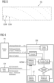
- FIG 5 is an enlarged section of one of the BG areas
- FIG 2 represents, illustrates.
- the marking of the areas BG means that a deviation of the at least one variable at a specific position on the tool path WB1, WB2 can be immediately determined and read.
- the information in the marking makes it possible, among other things, to determine the cause of the speed drops that led to the BG areas.
- the position can be displayed in color, for example as a colored dot, and/or the extent of deviation according to a color scale.
- the points can be designed differently.
- FIG 5 reveals three points GSW, which are shown as filled circles. All other points can be seen as empty circles.
- a filled circle can be represented as a red dot and an empty circle as a green dot.
- the reference symbol "GSW” and the arrows pointing to the points can also be visualized.
- the displayed “GSW” can contain an indication of which limit value or user-defined threshold value was reached or exceeded for which axis and/or channel.
- the process data PD includes data representative of the position of the at least one axis, in particular position data of the axis, which are preferably representative of the tool position.
- the at least one variable can be determined, for example, from position data by derivation (according to time).
- the tool path WB1, WB2 can be visualized as a 2D or 3D contour or line. More dimensions for visualization are also conceivable: 3D contour and coloring (of the point cloud) - 4D; 3D contour and coloring and line thickness - 5D; 3D and 3D vector (to show curvature direction, for example) - 6D.
- the tool path analysis component 20 can also be configured to generate the additional signal when the at least one variable exceeds a threshold value that is dependent on the at least one limit value, for example predetermined by an operator.
- the threshold value can be set, for example, as a fraction of the limit value.
- the marking can preferably indicate or contain information about the percentage by which the threshold value has been exceeded.
- FIG 4 shows a machine tool 100, for example a system 1 of FIG 1 can include.
- the machine tool 100 can have multiple axes, for example feed axes, for moving the tool 101 and a control device that includes an NC controller 102 for controlling the axes.
- the machine tool 100 is a 5- or 6-axis machine tool.
- the machine tool 100 usually processes a workpiece 103. This is preferably subtractive processing. It goes without saying that the system 1 can also be used in an additive manufacturing process.
- the system 1 can be implemented, for example, in the control device, in particular in the NC control 102.
- the control device can also include further units that are structurally separate from the NC control 102, for example.
- control device may include an edge device 105.
- the edge device 105 can, for example, be designed as an industrial computer and be set up to record the process data PD, cache it, pre-process it, make it available to a cloud platform (not shown here), etc.
- the system 1 can also be implemented in such an edge device 105 and, for example, the display device 104 Use the NC control 102 to visualize the signals Sx, Sy, Sz and the additional signal ZS.
- the control device can also include one or more other preferably mobile devices 106, for example smartphone, laptop, tablet, etc.
- the system 1 can be in each of these, for example via a local network with the edge device 105 and/or with the NC Controller 102 connected devices are implemented. Alternatively or additionally, the devices 106 may be connected to the cloud platform.
- the tool path analysis component 20 is configured to obtain the process data PD during operation, i.e., during operation of the machine tool 100. This means that process data PD is received in real time.
- the tool path analysis component 20 can be configured to determine the at least one quantity for each axis and to check whether the at least one limit value has been reached or exceeded.
- Different axes can be assigned different limit values for the at least one variable, whereby the tool path analysis component 20 can be configured to check for each axis whether the corresponding at least one limit value has been reached or exceeded.
- the tool path analysis component 20 can be set up to generate different additional signals for different axes, which preferably lead to different (eg in design) identification.
- each axis can be assigned a specific color of identification, and different colors can be used for different axes.
- the parameterization of the NC control 102 preferably has at least one limit value for the at least one variable for each axis.
- control device in particular NC control 102, includes a machine-executable program code, for example a part program or G-code file.
- FIG 6 shows a flowchart showing a computer-aided method for automatically supporting an inspection and/or monitoring of a subtractive machining process, which is carried out when a tool path analysis component runs on a computing device, for example the tool path analysis component 20 on the control device.
- the tool path analysis component 200 receives process data PD that is representative of the machining process during operation of the machine tool.
- the process data PD can include, for example, the following information.
- the machine tool is, for example, a five-axis machine tool, so that the process data PD includes axis position A1, ..., A5 ("Axis position [A1, ..., A5]" in FIG 6 ).
- the process data PD includes tool positions in the spatial or workpiece coordinate system u1, u2, u3.
- the process data PD can contain information about which G function, ie a specific function in the part program that is executed on the control device, in particular on the NC control, is currently active ("Active G function" in FIG 6 ). In this way it is possible to create a relationship between the G-code lines and the process data PD.
- a specific G function can be assigned to the axis positions A1, ..., A5 and the tool positions u1, u2, u3.
- the process data PD can be sent to the tool path analysis component 200 in the form of corresponding signals (see FIG 6 ) to provide.
- the tool path analysis component 200 receives limit values GW assigned to the corresponding axes and the corresponding quantities.
- the GW limits include limit values in machine coordinates - the "MCS limits" MAX_AX_SCHW[0..5] ⁇ 1..5>; MAX_AX_BESCHL[0..5] ⁇ 1..5>; MAX_AX_RUCK[0..5] ⁇ 1..5> - and the limit values in spatial/workpiece coordinates - the "WCS limit values" MAX_BAHN_RUCK[0..5].
- the tool path analysis component can include 200 user-defined limits or thresholds UT - SPEED_LIM [in % of limit], ACCE_LIM [in % of limit], RUCK_LIM [in % of limit], where each barrier corresponds to a limit.
- the tool path analysis component 200 can expediently have an interface, in particular a user interface, via which the limits or the threshold values can be changed.
- the limit values GW and/or the user-defined limits UT can be supplied to one or more machine tool models WZMM, which includes, for example, the tool path analysis component 200.
- the machine tool models WZMM include the limit values GW and the user-defined limits UT. This means that the limit values GW can be stored in the tool path analysis component 20 or the tool path analysis component 20 can download the limit values GW from the NC control.
- the tool path analysis component From the process data PD, the tool path analysis component generates 200 signals to visualize the tool path.
- the tool path can be displayed in the form of a point cloud in a Cartesian coordinate system ("Show point cloud" in FIG 6 ).
- speed, acceleration, shock, speed-related and position-related jerk can be determined by deriving them based on time - AKT_AX_SCHW ⁇ 1 ..5>;AKT_AX_BESCHL ⁇ 1..5>;AKT_AX_RUCK ⁇ 1..5>; and AKT_BAHN_RUCK[0..5] ("Determine size" in FIG 6 ).
- the variables that characterize the axis movement of the corresponding axis are determined.
- each point on the tool path it is then checked whether the determined variable reaches or exceeds at least one limit value assigned to this variable.
- Each point can be associated with the G function that is executed to create that point.
- the tool path analysis component 200 If one of the corresponding limit values MAX_AX_SPEED[0..5] ⁇ 1..5>, MAX_AX_BESCHL[0..5] ⁇ 1..5>, MAX_AX_RUCK[0..5] ⁇ 1..5>, MAX_BAHN_RUCK[0 ..5] or if one of the user-defined threshold values is reached or exceeded, the tool path analysis component 200 generates at least one additional signal for visually identifying the area of the tool path at which the limit value or the user-defined threshold value was reached or exceeded.
- an area can be marked using the additional signal or signals, for example point by point, and the marking can be visualized ("mark the area of the point cloud" in FIG 6 ).
- the points of the point cloud that are in the aforementioned areas BG or in the aforementioned regions can be colored with a different color.
- information in the form of a text “GSW” can also be displayed for respective points ( FIG 5 ), which, for example, indicates which limit value or user-defined threshold value was reached or exceeded for which axis and/or channel.
- the text can contain the following information: "The speed value for axis B1 is 98% of the limit value".
- the control of the machine tool can be optimized. For example, the parameterization of the NC control 102 and in particular the individual G functions can be adjusted. This can reduce the number of speed drops.
Abstract
System zur automatisierten Unterstützung einer Inspektion und/oder Überwachung eines Bearbeitungsprozess umfassend einen Speicher (2) zum Speichern von maschinenausführbaren Komponenten und einen Prozessor (3), der operativ mit dem Speicher (2) gekoppelt ist und dazu konfiguriert ist, die maschinenausführbaren Komponenten auszuführen, wobei die maschinenausführbaren Komponenten eine Werkzeugbahnanalyse-Komponente (20, 200) umfassen, wobei die Werkzeugbahnanalyse-Komponente (20, 200) dazu konfiguriert ist, aus Prozessdaten (PD), wobei die Prozessdaten (PD) für einen Bearbeitungsprozess repräsentativ sind, welcher von einer zumindest eine Achse zum Bewegen eines Werkzeugs (101) und eine Steuereinrichtung (102) zum Steuern der zumindest einen Achse aufweisenden Werkzeugmaschine (100) ausgeführt wird, Signale (Sx, Sy, Sz) zur Visualisierung einer Bahn des Werkzeugs - einer Werkzeugbahn (WB1, WB2) - zu generieren, und zumindest eine Größe zu ermitteln, welche eine Achsenbewegung der zumindest einen Achse charakterisiert, zu prüfen, ob die ermittelte Größe zumindest einen, der zumindest einen Größe zugewiesenen Grenzwert (GW) erreicht oder überschreitet, beim Erreichen oder Überschreiten des Grenzwerts (GW) zumindest ein Zusatzsignal (ZS) zur Kennzeichnung zumindest eines Bereichs (BG) der Werkzeugbahn (WB1, WB2), an dem der Grenzwert überschritten ist, zu generieren.System for automated support of an inspection and/or monitoring of a machining process, comprising a memory (2) for storing machine-executable components and a processor (3) which is operatively coupled to the memory (2) and is configured to execute the machine-executable components, wherein the machine-executable components include a tool path analysis component (20, 200), wherein the tool path analysis component (20, 200) is configured to process data (PD), the process data (PD) being representative of a machining process which is of a at least one axis for moving a tool (101) and a control device (102) for controlling the machine tool (100) having at least one axis, signals (Sx, Sy, Sz) for visualizing a path of the tool - a tool path (WB1, WB2) - to generate, and to determine at least one variable which characterizes an axis movement of the at least one axis, to check whether the determined variable reaches or exceeds at least one limit value (GW) assigned to at least one variable when reaching or exceeding the Limit value (GW) to generate at least one additional signal (ZS) for identifying at least one area (BG) of the tool path (WB1, WB2) where the limit value is exceeded.
Description
Die vorliegende Offenbarung betrifft ein System zur automatisierten Unterstützung einer Inspektion und/oder Überwachung eines mittels einer Werkzeugmaschine ausgeführten Prozesses umfassend einen Speicher zum Speichern von maschinenausführbaren Komponenten und einen Prozessor, der operativ mit dem Speicher gekoppelt ist und dazu konfiguriert ist, die maschinenausführbaren Komponenten auszuführen, wobei die maschinenausführbaren Komponenten eine Werkzeugbahnanalyse-Komponente umfassen, wobei die Werkzeugbahnanalyse-Komponente dazu konfiguriert ist, aus Prozessdaten, wobei die Prozessdaten für einen Prozess repräsentativ sind, welcher von einer zumindest eine Achse zum Bewegen eines Werkzeugs und eine Steuereinrichtung zum Steuern der zumindest einen Achse aufweisenden Werkzeugmaschine ausgeführt wird, um beispielsweise ein Werkstück zu bearbeiten oder zu fertigen, Signale zur Visualisierung einer Bahn des Werkzeugs - einer Werkzeugbahn - zu generieren, und zumindest eine Größe zu ermitteln, welche eine Achsenbewegung der zumindest einen Achse charakterisiert.The present disclosure relates to a system for automated support of inspection and/or monitoring of a process performed by a machine tool, comprising a memory for storing machine-executable components and a processor operatively coupled to the memory and configured to execute the machine-executable components, wherein the machine-executable components include a tool path analysis component, the tool path analysis component being configured to process data, the process data being representative of a process consisting of at least one axis for moving a tool and a controller for controlling the at least one axis having machine tool is carried out, for example, to machine or manufacture a workpiece, to generate signals for visualizing a path of the tool - a tool path -, and to determine at least one variable which characterizes an axis movement of the at least one axis.
Außerdem wird ein computergestütztes Verfahren zur automatisierten Unterstützung einer Inspektion und/oder Überwachung eines mittels einer Werkzeugmaschine ausgeführten Prozesses, wobei aus, insbesondere während des Betriebs, z.B. in Echtzeit, der Werkzeugmaschine erhaltenen Prozessdaten, wobei die Prozessdaten für einen Prozess repräsentativ sind, welcher von einer zumindest eine Achse zum Bewegen eines Werkzeugs und eine Steuereinrichtung zum Steuern der zumindest einen Achse aufweisenden Werkzeugmaschine ausgeführt wird, um ein Werkstück zu bearbeiten, Signale zur Visualisierung einer Bahn des Werkzeugs - einer Werkzeugbahn - generiert werden, und zumindest eine Größe, beispielsweise durch Ableiten, ermittelt wird, welche eine Achsenbewegung der zumindest einen Achse charakterisiert.In addition, a computer-aided method for the automated support of an inspection and/or monitoring of a process carried out by means of a machine tool, wherein process data obtained from the machine tool, in particular during operation, for example in real time, the process data being representative of a process which is carried out by a at least one axis for moving a tool and a control device for controlling the machine tool having at least one axis is executed in order to machine a workpiece, signals for visualizing a path of the tool - a tool path - are generated, and at least one size, for example by deriving, is determined, which characterizes an axis movement of the at least one axis.
Darüber hinaus wird eine Steuereinrichtung, eine Werkzeugmaschine und ein Computerprogramm offenbart.In addition, a control device, a machine tool and a computer program are disclosed.
Bei mittels Werkzeugmaschinen und/oder Robotern ausgeführten Prozessen ist es wichtig, den Vorschub, also die Geschwindigkeit, mit der die Relativbewegung zwischen Werkzeug und Werkstück ausgeführt wird, zu überwachen.In processes carried out using machine tools and/or robots, it is important to monitor the feed, i.e. the speed at which the relative movement between the tool and the workpiece is carried out.
Je nach Prozess beziehungsweise Art des Prozesses ist ein prozessoptimaler Vorschub erforderlich. Der Vorschub des Werkzeugs ist in der spanenden Fertigung in Teilprozessen wie z.B. Schlichten ein wichtiges Kriterium, um Werkstücke mit hoher Oberflächenqualität fertigen zu können.Depending on the process or type of process, a process-optimal feed rate is required. The feed of the tool is an important criterion in machining production in sub-processes such as finishing in order to be able to produce workpieces with high surface quality.
Oft ist es wünschenswert, einen homogenen Vorschub, d.h. stetige Vorschubänderungen im Rahmen der verfügbaren Dynamik der Maschine sicherzustellen.It is often desirable to ensure a homogeneous feed, i.e. constant changes in feed within the available dynamics of the machine.
Ungewollte Geschwindigkeitseinbrüche führen zu Qualitätseinbüßen in der Oberflächenqualität, erhöhen der Verschleiß an Werkzeugen und Maschine, können zu einem Werkzeugbruch führen.Unintentional drops in speed lead to a loss of surface quality, increase wear on tools and machines, and can lead to tool breakage.
Kommt es beispielsweise zu einem (im Raum lokalen) Geschwindigkeitsabfall beziehungsweise -einbruch in der subtraktiven oder additiven Fertigung, kann sich dies später am fertigen Werkstück als Marke zeigen, weil beispielsweise am Ort des Geschwindigkeitseinbruchs mehr Material abgetragen oder hinzugefügt wurde als bei homogenem Vorschub. In Industrien mit hohen Anforderungen an die Oberflächenqualität führt dies oftmals zu Ausschuss.For example, if there is a (local spatial) drop or drop in speed in subtractive or additive manufacturing, this can later show up as a mark on the finished workpiece because, for example, more material was removed or added at the location of the drop in speed than with homogeneous feed. In industries with high demands on surface quality, this often leads to rejects.
Als Beispiel seien 5-Achsmaschinen und Maschinen mit nicht kartesischem Achsaufbau (z.B. Hexapoden) genannt. Für die Festlegung der Verfahrbewegungen sind zwei typische Varianten bekannt.Examples include 5-axis machines and machines with a non-Cartesian axis structure (e.g. hexapods). Two typical variants are known for defining the traversing movements.
Der Anwender kann die Raumkontur entweder über Kreis oder Gerade beziehungsweise Polynomform programmieren, sodass der TCP (für engl. Tool-Center-Point) entsprechend dem programmierten Konturverlauf auf der Bahn geführt wird.The user can program the spatial contour using either a circle or a straight line or a polynomial shape, so that the TCP (tool center point) is guided along the path according to the programmed contour.
Alternativ kann der Anwender den Zielpunkt in Raum/Werkstücckoordinaten (WCS für engl. workpiece coordinate system) programmieren, die in Maschinenkoordinaten (MCS machine coordinate system) abgebildet werden. Der TCP bewegt sich entsprechend den maximal möglichen Geschwindigkeiten in den Achsen auf einer nicht einfach vorhersehbaren Kurve (PTP für engl. Point-to-Point). Bedingt durch den Wegfall der Bewegung des TCP entlang einer Raumkurve ist die PTP-Bewegung schneller als die TCP-Bahnbewegung ist. Die PTP-Bewegung ist schneller, weil sie direkt ist (der PTP-Weg ist der kürzeste). Die beteiligten Maschinenachsen fahren direkt ohne Berücksichtigung von Zwangsbedingungen aus einer angewählten Koordinatentransformation direkt auf die WCS-Zielposition.Alternatively, the user can program the target point in space/workpiece coordinates (WCS), which are mapped in machine coordinates (MCS machine coordinate system). The TCP moves according to the maximum possible speeds in the axes on a curve that is not easily predictable (PTP for point-to-point). Due to the elimination of the movement of the TCP along a spatial curve, the PTP movement is faster than the TCP path movement. PTP movement is faster because it is direct (the PTP path is the shortest). The machine axes involved move directly from a selected coordinate transformation to the WCS target position without taking any constraints into account.
Aus dem Stand der Technik sind Verfahren bekannt, bei welchen anhand der Prozessdaten, die beispielsweise während eines Fräsprozesses oder eines additiven Fertigungsprozesses aufgezeichnet worden sind, die Geschwindigkeit, die Beschleunigung oder der Ruck der Bewegung des TCP sichtbar gemacht werden kann. Dabei kann die TCP-Bahn beispielsweise mit der Vorschubgeschwindigkeit eingefärbt werden.Methods are known from the prior art in which the speed, acceleration or jerk of the movement of the TCP can be made visible using the process data recorded, for example, during a milling process or an additive manufacturing process. The TCP path can be colored with the feed rate, for example.
Mit anderen Worten kann aus Prozessdaten die Geschwindigkeit ermittelt und entlang der Werkzeugbahn entsprechend gekennzeichnet werden, indem die Werkzeugbahn beispielsweise entsprechend der ermittelten Geschwindigkeit eingefärbt wird.In other words, the speed can be determined from process data and marked accordingly along the tool path, for example by coloring the tool path according to the determined speed.
Eine solche Einfärbung ist allerdings nicht ausreichend, wenn die (lokalen) Geschwindigkeitseinbrüche und ihre Ursache identifiziert werden sollen, um sie in Zukunft zu vermeiden. Dabei reicht oft nicht die Expertise von Mechatronik-Experten aus, die Prozessdaten an der Werkzeugmaschine aufzeichnen und mit eigenen Tools analysieren (z.B. Matlab). Ohnehin ist dieses Wissen bei den Anwendern / Bedienern der Werkzeugmaschine selten vorhanden.However, such coloring is not sufficient if the (local) speed drops and their cause are to be identified in order to avoid them in the future. The expertise of mechatronics experts who record process data on the machine tool and analyze it with their own tools (e.g. Matlab) is often not sufficient. Anyway, this is it Knowledge is rarely present among the users/operators of the machine tool.
Die Aufgabe, die der vorliegenden Offenbarung zugrunde liegt, ist, Systeme und Verfahren bereitzustellen, die ermöglichen, die Geschwindigkeitseinbrüche in Fertigungsprozessen einfacher zu identifizieren und auf ihre Ursache rückzuschließen.The task on which the present disclosure is based is to provide systems and methods that make it easier to identify drops in speed in manufacturing processes and to draw conclusions about their cause.
Diese Aufgabe wird mit einem System der oben genannten Art erfindungsgemäß dadurch gelöst, dass die Werkzeugbahnanalyse-Komponente dazu konfiguriert ist, zu prüfen, ob die ermittelte Größe zumindest einen, der zumindest einen Größe zugewiesenen Grenzwert überschreitet, beim Überschreiten des Grenzwerts zumindest ein Zusatzsignal zur, vorzugsweise visuellen, Kennzeichnung zumindest eines Bereichs der Werkzeugbahn, an dem der Grenzwert überschritten ist, zu generieren.This object is achieved according to the invention with a system of the type mentioned above in that the tool path analysis component is configured to check whether the determined variable exceeds at least one limit value assigned to at least one variable, and if the limit value is exceeded, at least an additional signal for, preferably visual, to generate identification of at least one area of the tool path where the limit value is exceeded.
Hierdurch wird eine Abweichung der zumindest einen Größe an einer bestimmten Position unmittelbar feststellbar und ablesbar.This makes a deviation of at least one variable at a specific position immediately detectable and readable.
Eine "unmittelbare Ablesbarkeit" kann beispielsweise dadurch erreicht werden, dass die Position in Farbe, beispielsweise als ein gefärbter Punkt, angezeigt wird und das Ausmaß der Abweichung gemäß einer Farbskala visualisiert wird.“Immediate readability” can be achieved, for example, by displaying the position in color, for example as a colored dot, and visualizing the extent of the deviation according to a color scale.
Bediener können nun Maßnahmen ergreifen und den Prozess so verändern, dass die dynamikbegrenzende Wirkung aufgrund des Erreichens oder des Überschreitens des zumindest einen Grenzwerts reduziert oder beseitigt wird. Die Maßnahmen können eine oder mehrere Maßnahmen aus der Gruppe umfassen: NC-Teileprogrammänderung, Aufspannsituation im Arbeitsraum der Maschine verändern, Werkzeuglängen und gegebenenfalls Werkzeugorientierungen ändern.Operators can now take measures and change the process so that the dynamic-limiting effect due to reaching or exceeding at least one limit value is reduced or eliminated. The measures can include one or more measures from the group: NC part program change, changing the clamping situation in the machine's work area, changing tool lengths and, if necessary, tool orientations.
Die Prozessdaten enthalten beispielsweise von an und/oder in der Werkzeugmaschine angebrachten bzw. angeordneten Sensoren erfasste Messwerte und/oder aus den Messwerten abgeleitete Daten.The process data contains, for example, sensors attached or arranged on and/or in the machine tool recorded measured values and/or data derived from the measured values.
Der Prozess kann beispielsweise ein subtraktiver oder additiver Bearbeitungsprozess beziehungsweise Fertigungsprozess sein. Somit kann es sich beim Werkzeug um ein Zerspanungswerkzeug oder Scheidwerkzeug zum Bohren, Fräsen, Drehen, Schleifen, Honen, etc. oder um ein Laser oder eine Düse handeln.The process can be, for example, a subtractive or additive machining process or manufacturing process. The tool can therefore be a cutting tool or cutting tool for drilling, milling, turning, grinding, honing, etc. or a laser or a nozzle.
Es ist auch denkbar, dass der Prozess ein Messprozess ist, bei dem beispielsweise ein Werkstück ausgemessen beziehungsweise vermessen wird. Bei dem Werkzeug kann es sich somit um ein Messwerkzeug handeln, beispielsweise um eine Sensorvorrichtung, insbesondere um einen Sensor, z.B. einen Laserscanner, Ultraschallsensor oder Parabolspiegel, die in einer Werkzeugaufnahme eines Arms der Werkzeugmaschine befestigt werden kann.It is also conceivable that the process is a measuring process in which, for example, a workpiece is measured or measured. The tool can therefore be a measuring tool, for example a sensor device, in particular a sensor, for example a laser scanner, ultrasonic sensor or parabolic mirror, which can be fastened in a tool holder of an arm of the machine tool.
Beispielsweise kann es sich um einen Messprozess mit Ultraschallsensoren handeln. Bei so einem Prozess kann die Oberfläche eines Werkstücks, z.B. auf ihre Porosität, untersucht werden. Der Schall kann mit Hilfe von Wasserstrahlen einer Werkstückoberfläche (z.B. von mehreren Seiten) zugeführt werden. Anschließend kann die Reaktion des Werkstücks mit einem oder mehreren Ultraschallsensoren vermessen werden, wobei die Ultraschallsensoren in Werkzeugaufnahmen positioniert sein können und somit ein "Messwerkzeug" darstellen.For example, it can be a measuring process using ultrasonic sensors. With such a process, the surface of a workpiece can be examined, for example for its porosity. The sound can be delivered to a workpiece surface (e.g. from several sides) using water jets. The reaction of the workpiece can then be measured with one or more ultrasonic sensors, whereby the ultrasonic sensors can be positioned in tool holders and thus represent a “measuring tool”.
Es versteht sich, dass es sich bei einer Werkzeugmaschine auch um einen Roboter beziehungsweise einen Roboterarm handeln kann, da ein Roboter - aus steuertechnischer Sicht - als eine Werkzeugmaschine mit einer Roboterkinematik angesehen werden kann. Die Roboter weisen - hauptsächlich - Rundachsen auf.It is understood that a machine tool can also be a robot or a robot arm, since a robot - from a control perspective - can be viewed as a machine tool with robot kinematics. The robots have - mainly - rotary axes.
Bei einer Ausführungsform kann es vorgesehen sein, dass die Werkzeugbahnanalyse-Komponente dazu konfiguriert ist, die Signale und das Zusatzsignal an einer Anzeigeeinrichtung zu visualisieren.In one embodiment, it may be provided that the tool path analysis component is configured to: Visualize signals and the additional signal on a display device.
Bei einer Ausführungsform kann es vorgesehen sein, dass die Steuereinrichtung eine Parametrierung aufweist, wobei die Parametrierung den zumindest einen Grenzwert umfasst.In one embodiment, it can be provided that the control device has a parameterization, wherein the parameterization includes the at least one limit value.
Bei dem Grenzwert kann es sich beispielsweise um eine Dynamikgrenze der Achse, beispielsweise der Vorschubachse der Werkzeugmaschine handeln.The limit value can be, for example, a dynamic limit of the axis, for example the feed axis of the machine tool.
Eine mögliche Ursache für Geschwindigkeitseinbrüche sind die Dynamikgrenzen der Vorschubachsen der Werkzeugmaschine. Jede Maschinenachse hat eine vom Maschinenhersteller festgelegte Geschwindigkeits-, Beschleunigungs- und Ruckgrenze. Darüber hinaus kann noch eine auf die Werkzeugbahn (Tool Center Point) bezogene Ruckgrenze vorgesehen sein. Die Dynamikgrenzen sind Teil der Parametrierung der CNC (NC-Steuerung). Sie begrenzen die Dynamik der Achsen entsprechend der konstruktiven, elektrischen oder regelungstechnischen Vorgaben / Projektierung des Inverkehrbringers / Maschinenherstellers.A possible cause of speed drops are the dynamic limits of the feed axes of the machine tool. Each machine axis has a speed, acceleration and jerk limit set by the machine manufacturer. In addition, a jerk limit related to the tool path (tool center point) can be provided. The dynamic limits are part of the parameterization of the CNC (NC control). They limit the dynamics of the axes according to the design, electrical or control specifications/project planning of the distributor/machine manufacturer.
Mit anderen Worten kann durch die Dynamikgrenzen unter anderem gewährleistet werden, dass die entsprechenden Achsen nicht Kräfte erfahren, die beispielsweise zu ihren konstruktiven irreversiblen Veränderungen führen können.In other words, the dynamic limits can, among other things, ensure that the corresponding axes do not experience forces that can, for example, lead to their constructive irreversible changes.
Bei Robotern (geringere Steifigkeit und deshalb geringere Eigenfrequenzen) können durch die Dynamikgrenzen bestimmte Schwingungen reduziert beziehungsweise vermieden werden.In robots (lower rigidity and therefore lower natural frequencies), certain vibrations can be reduced or avoided through the dynamic limits.
Wird eine Achse schneller als vom Teileprogramm vorgegeben verfahren, kann dies zu einem oder mehreren Geschwindigkeitseinbrüchen, weil die Steuereinrichtung, beispielsweise die CNC den Vorschub reduziert, um die Dynamikgrenzen nicht zu überschreiten.If an axis moves faster than specified by the part program, this can lead to one or more drops in speed because the control device, for example the CNC, reduces the feed in order not to exceed the dynamic limits.
Bei einer Ausführungsform kann es vorgesehen sein, dass die Prozessdaten für Position der zumindest einen Achse und/oder des Werkzeugs repräsentative Daten, insbesondere Positionsdaten der Achse, die vorzugsweise für Werkzeugposition repräsentativ sind, umfassen.In one embodiment, it can be provided that the process data includes data representative of the position of the at least one axis and/or the tool, in particular position data of the axis, which are preferably representative of the tool position.
Anschließend kann die Werkzeugbahnanalyse-Komponente beispielsweise über die Ableitung des Werkzeugpfades (der Werkzeugbahn) beziehungsweise der Positionen der Maschinenachsen nach der Zeit die tatsächlichen Geschwindigkeiten, Beschleunigungen und Rücke ermitteln. Die Werkzeugbahnanalyse-Komponente kann dann beispielsweise prüfen, ob an den jeweiligen Koordinaten eine der Dynamikgrenzen überschritten wurde.The tool path analysis component can then determine the actual speeds, accelerations and displacements over time, for example by deriving the tool path (the tool path) or the positions of the machine axes over time. The tool path analysis component can then, for example, check whether one of the dynamic limits has been exceeded at the respective coordinates.
Bei einer Ausführungsform kann es vorgesehen sein, dass die Werkzeugbahnanalyse-Komponente beispielsweise über eine Farbkodierung und Zusatzinformation darauf hinweist, wo in der Punktewolke, die die Visualisierung der Werkzeugbahn bildet, welche Dynamikgrenze überschritten worden ist.In one embodiment, it can be provided that the tool path analysis component indicates, for example via color coding and additional information, where in the point cloud that forms the visualization of the tool path which dynamic limit has been exceeded.
Dadurch kann die Information darüber gewonnen werden, wo genau am Werkstück die Grenzwerte, insbesondere die Dynamikgrenzen erreicht oder überschritten wurden. Ist beispielsweise an einer bestimmten Stelle im Werkstück eine ungewünschte und entsprechend gekennzeichnete Oberflächenmarke oder ein sonstiger lokaler Geschwindigkeitseinbruch ersichtlich, so kann dieser Effekt mit dem Überschreiten oder Erreichen des Grenzwertes und insbesondere der Dynamikgrenzen der jeweiligen Achse oder eines Maschinenkanals in Verbindung gebracht werden.This allows information to be obtained about exactly where on the workpiece the limit values, in particular the dynamic limits, have been reached or exceeded. If, for example, an undesirable and correspondingly marked surface mark or another local drop in speed is visible at a certain point in the workpiece, this effect can be associated with exceeding or reaching the limit value and in particular the dynamic limits of the respective axis or a machine channel.
Es bietet sich dann die Möglichkeit, entweder das Teileprogramm anzupassen oder die Aufspannsituation zu ändern, sodass die Grenzwerte nicht mehr erreicht werden.This then offers the option of either adapting the part program or changing the clamping situation so that the limit values are no longer reached.
Beispielsweise können für verschiedene G-Funktionen unterschiedliche Dynamikgrenzen gelten.For example, different dynamic limits may apply to different G functions.
Bei einer Ausführungsform kann es vorgesehen sein, dass die Prozessdaten einen Bezug zum Teileprogramm aufweisen, welches auf der Steuereinrichtung und insbesondere auf einer NC-Steuerung (NC für engl. numerical control) abläuft. Insbesondere enthalten die Prozessdaten Bezug zu bestimmten G-Funktionen (die z.B. bestimmten Dynamikgruppen der Werkzeugmaschine, z.B. Schlicht-, Schruppbearbeitung, Positionieren etc. entsprechen können) und vorzugsweise zu G-Code-Zeilen, sodass die Suche nach möglichen Fehlern und Ursachen vereinfacht wird.In one embodiment, it can be provided that the process data has a reference to the part program that runs on the control device and in particular on an NC control (NC for numerical control). In particular, the process data contains references to certain G functions (which can correspond, for example, to certain dynamic groups of the machine tool, e.g. finishing, roughing, positioning, etc.) and preferably to G code lines, so that the search for possible errors and causes is simplified.
Die Prozessdaten können also einen Bezug zu einem Teileprogramm für den Bearbeitungsprozess beziehungsweise zu dem Teileprogramm des Bearbeitungsprozesses aufweisen, wobei die Prozessdaten insbesondere einen Bezug zu G-Funktionen des Teileprogramms und vorzugsweise zu G-Code-Zeilen Teileprogramms enthaltenThe process data can therefore have a reference to a part program for the machining process or to the part program of the machining process, the process data in particular containing a reference to G functions of the part program and preferably to G code lines of the part program
Mit anderen Worten können die Prozessdaten folgende Informationen umfassen. Die Prozessdaten können Achsenposition jeder Achse einer mehrachsigen (3, 4, 5, 6, ...) Werkzeugmaschine umfassen. Darüber hinaus können die Prozessdaten Werkzeugpositionen im Raum- beziehungsweise Werkstückkoordinatensystem umfassen. Außerdem können die Prozessdaten Information darüber aufweisen, welche G-Funktion, d. h. eine bestimmte Funktion im Teileprogramm, gerade aktiv ist (wenn das Verfahren in Echtzeit ausgeführt wird) oder aktiv war. Die Prozessdaten können also einen Bezug zwischen den Achsenpositionen, den Werkzeugpositionen und den bestimmten G-Funktionen enthalten, sodass bestimmte G-Funktionen den Achsenpositionen und den Werkzeugpositionen zugewiesen werden können.In other words, the process data can include the following information. The process data can include axis position of each axis of a multi-axis (3, 4, 5, 6, ...) machine tool. In addition, the process data can include tool positions in the spatial or workpiece coordinate system. In addition, the process data can contain information about which G function, i.e. H. a specific function in the part program is currently active (if the process is carried out in real time) or was active. The process data can therefore contain a relationship between the axis positions, the tool positions and the specific G functions, so that specific G functions can be assigned to the axis positions and the tool positions.
Bei einer Ausführungsform kann es vorgesehen sein, dass die Werkzeugbahnanalyse-Komponente dazu konfiguriert ist, aus den Signalen zur Visualisierung der Werkzeugbahn, die beispielsweise in einem Werkstückkoordinatensystem generiert werden, Positionsdaten der zumindest einen Achse, beispielsweise in einem Werkzeugmaschinenkoordinatensystem zu ermitteln. Hierdurch wird die Erkenntnis erlangt, welche Achse und wie, in Bezug auf das Werkstückkoordinatensystem, beteiligt war.In one embodiment, it can be provided that the tool path analysis component is configured to determine position data of the at least one axis, for example in a machine tool coordinate system, from the signals for visualizing the tool path, which are generated, for example, in a workpiece coordinate system. Through this The knowledge is gained as to which axis and how, in relation to the workpiece coordinate system, was involved.
Bei einer Ausführungsform kann es vorgesehen sein, dass die zumindest eine Größe eine physikalische, zeitabhängige Größe ist, die die Achsenbewegung vorzugsweise unmittelbar beschreibt.In one embodiment, it can be provided that the at least one variable is a physical, time-dependent variable that preferably directly describes the axis movement.
Bei einer Ausführungsform kann es vorgesehen sein, dass die zumindest eine Größe Geschwindigkeit, Beschleunigung, Ruck oder Stoß ist. Dabei kann es sich um einen auf die Geschwindigkeit bezogenen und/oder auf die Position bezogenen Ruck handeln.In one embodiment it can be provided that the at least one variable is speed, acceleration, jerk or shock. This can be a speed-related and/or position-related jerk.
Bei den Grenzwerten kann es sich um eine oder mehrere der folgenden Dynamikgrenzen der Maschine handeln: maximale Achsengeschwindigkeit - MAX AX_GESCHW, maximale Achsenbeschleunigung - MAX_AX_BESCHL, maximaler Achsenruck - MAX_AX_RUCK, maximaler Ruck der Werkzeugspitze - MAX_BAHN_RUCK. Diese Grenzen können im Teileprogramm geändert, angepasst werden.The limit values can be one or more of the following dynamic limits of the machine: maximum axis speed - MAX AX_SPEED, maximum axis acceleration - MAX_AX_BESCHL, maximum axis jerk - MAX_AX_RUCK, maximum tool tip jerk - MAX_BAHN_RUCK. These limits can be changed and adjusted in the part program.
Die Dynamikgrenzen sind üblicherweise in der Maschinenkonfiguration (in Kanal- beziehungsweise Achsmaschinendaten) abgelegt und können der Werkzeugbahnanalyse-Komponente zur Verfügung gestellt oder von der Werkzeugbahnanalyse-Komponente abgerufen werden.The dynamic limits are usually stored in the machine configuration (in channel or axis machine data) and can be made available to the tool path analysis component or retrieved from the tool path analysis component.
Die Werkzeugbahn eine von dem Werkzeug, insbesondere von dem Tool-Center-Point (z.B. von der Werkzeugspitze oder von dem Werkzeugmittelpunkt (bei Kugelfräsern)) hinterlegte oder, wenn der Prozess vor seiner tatsächlichen Durchführung simuliert wird, zu hinterlegende Trajektorie (Bewegungsweg oder Bahn) ist.The tool path is a trajectory (movement path or path) stored by the tool, in particular by the tool center point (e.g. from the tool tip or from the tool center (for ball mills)) or, if the process is simulated before it is actually carried out, to be stored. is.
Bei einer Ausführungsform kann es vorgesehen sein, dass die Visualisierung eine 2D- oder 3D-Visualisierung ist.In one embodiment, it can be provided that the visualization is a 2D or 3D visualization.
Bei einer Ausführungsform kann es vorgesehen sein, dass die die Werkzeugbahnanalyse-Komponente dazu konfiguriert ist, die Prozessdaten im Betrieb, i.e., während des Betriebs der Werkzeugmaschine zu erhalten. Es handelt sich somit um Echtzeit-Daten.In one embodiment, it can be provided that the tool path analysis component is configured to obtain the process data during operation, i.e., during operation of the machine tool. This is therefore real-time data.
Bei einer Ausführungsform kann es vorgesehen sein, dass die Werkzeugbahnanalyse-Komponente dazu konfiguriert ist, das Zusatzsignal oder ein weiteres Zusatzsignal zu generieren, wenn die zumindest eine Größe einen, z.B. von einem Bediener vorgebbaren von dem zumindest einen Grenzwert abhängigen Schwellenwert überschreitet. Der Schwellenwert kann z.B. als Bruchteil von dem Grenzwert festgelegt werden.In one embodiment, it can be provided that the tool path analysis component is configured to generate the additional signal or a further additional signal when the at least one variable exceeds a threshold value that can be predetermined by an operator and is dependent on the at least one limit value. The threshold value can be set, for example, as a fraction of the limit value.
Insbesondere handelt es sich bei solchen Schwellenwerten um benutzerdefinierte Warngrenzen. Das Zusatzsignal oder das weitere Zusatzsignal wird somit dann generiert, wenn sich der Wert der zumindest einen Größe dem Grenzwert, beispielsweise der Dynamikgrenze zu nahe kommt.In particular, such thresholds are user-defined warning limits. The additional signal or the further additional signal is thus generated when the value of the at least one variable comes too close to the limit value, for example the dynamic limit.
Bei einer Ausführungsform kann es vorgesehen sein, dass die Achse eine Vorschubachse ist und die Achsenbewegung eine Vorschubbewegung ist.In one embodiment it can be provided that the axis is a feed axis and the axis movement is a feed movement.
Bei einer Ausführungsform kann es vorgesehen sein, dass die Werkzeugmaschine zwei oder mehr Achsen umfasst, wobei die Werkzeugbahnanalyse-Komponente dazu konfiguriert ist, die zumindest eine Größe für jede Achse zu ermitteln und die Überschreitung des zumindest einen Grenzwerts zu prüfen.In one embodiment, it can be provided that the machine tool comprises two or more axes, with the tool path analysis component being configured to determine the at least one size for each axis and to check whether the at least one limit value is exceeded.
Bei mehrachsigen Werkzeugmaschinen können zwei oder mehr Achsen (softwaretechnisch) zu einem (Werkzeugmaschinen-)Kanal zusammengefasst werden. Beispielsweise kann die Steuerung der Werkzeugmaschine beziehungsweise des Roboters so programmiert werden, dass mehrere Achsen gleichzeitig in einer gemeinsamen Bewegung (als eine Einheit) bewegt werden. In diesem Fall kann von einer Kanalbewegung gesprochen werden.In multi-axis machine tools, two or more axes can be combined (in terms of software) to form a (machine tool) channel. For example, the control of the machine tool or the robot can be programmed so that several axes are moved simultaneously in a common movement (as a unit). In this case we can speak of a channel movement.
Der Kanalbewegung kann ebenfalls Grenzwerte, z.B. Dynamikgrenzen zugewiesen werden. Beispielsweise kann die Parametrierung einer NC-Steuerung Kanal-Grenzwerte umfassen. Für gewöhnlich ist eine Kanalbewegung langsamer als die Bewegungen einzelner Achsen. Das Einhalten der der Kanalbewegung zugewiesenen Grenzwerte ist somit sicherer.Limit values, e.g. dynamic limits, can also be assigned to the channel movement. For example, the parameterization of an NC control can include channel limit values. Usually a channel movement is slower than the movements of individual axes. Compliance with the limit values assigned to channel movement is therefore safer.
Die Kanal-Grenzwerte stellen beispielsweise Dynamikgrenzen für das Zusammenwirken der Achsen auf Ihrer Bahn, Bahnruck, Bahngeschwindigkeit, Bahnbeschleunigung.The channel limit values set, for example, dynamic limits for the interaction of the axes on your path, path jerk, path speed, path acceleration.
Auch die Maschinendaten die die Bahn dynamisch begrenzen können hier relevant werden.The machine data that dynamically limit the path can also become relevant here.
Es kann dabei zweckmäßig sein, wenn unterschiedlichen Achsen unterschiedliche Grenzwerte für die zumindest eine Größe zugewiesen sind, wobei die Werkzeugbahnanalyse-Komponente dazu konfiguriert ist, die Überschreitung des entsprechenden zumindest einen Grenzwerts für jede Achse zu prüfen.It may be useful if different axes are assigned different limit values for the at least one variable, with the tool path analysis component being configured to check whether the corresponding at least one limit value is exceeded for each axis.
Darüber hinaus kann es mit Vorteil vorgesehen sein, wenn die Werkzeugbahnanalyse-Komponente dazu eingerichtet ist, für unterschiedliche Achsen unterschiedliche Zusatzsignale zu generieren, die vorzugsweise zur unterschiedlichen, z.B. in Gestaltung, Kennzeichnung führen.In addition, it can advantageously be provided if the tool path analysis component is set up to generate different additional signals for different axes, which preferably lead to different markings, for example in terms of design.
Die Aufgabe wird außerdem mit einer Steuereinrichtung mit oben beschriebenem System gelöst.The task is also solved with a control device with the system described above.
Bei einer Ausführungsform kann es vorgesehen sein, dass die Steuereinrichtung ein auf der Steuereinrichtung ausführbares Teileprogramm (NC-Programm, G-Code-File) aufweist. Beispielsweise kann die Steuereinrichtung eine NC-Steuerung umfassen beziehungsweise als eine NC-Steuerung ausgebildet sein. Darüber hinaus kann die Steuereinrichtung eine Rechenvorrichtung (z.B. einen industriellen Rechner (industrial PC), beispielsweise in Form eines Edge-Geräts, oder Laptop, etc.) umfassen.In one embodiment, it can be provided that the control device has a part program (NC program, G-code file) that can be executed on the control device. For example, the control device can include an NC control or be designed as an NC control. In addition, the control device can include a computing device (e.g. an industrial computer (industrial PC), for example in the form of an edge device, or laptop, etc.).
Die Aufgabe wird auch mit einer Werkzeugmaschine mit zumindest einer Achse zum Bewegen eines Werkzeugs, beispielsweise zum subtraktiven oder additiven Fertigen eines Werkstücks und mit einer oben genannten Steuereinrichtung.The task is also achieved with a machine tool with at least one axis for moving a tool, for example for subtractive or additive manufacturing of a workpiece, and with an above-mentioned control device.
Bei einer Ausführungsform kann es vorgesehen sein, dass die Werkzeugmaschine ferner eine der Steuereinrichtung zugeordnete Anzeigeeinrichtung umfasst, auf welcher die Signale und das Zusatzsignal, vorzugsweise gleichzeitig visualisierbar sind.In one embodiment, it can be provided that the machine tool further comprises a display device assigned to the control device, on which the signals and the additional signal can be visualized, preferably simultaneously.
Die Aufgabe wird außerdem mit einem eingangs genannten Verfahren erfindungsgemäß dadurch gelöst, dass geprüft wird, ob die ermittelte Größe zumindest einen, der zumindest einen Größe zugewiesenen Grenzwert überschreitet, beim Überschreiten des Grenzwerts zumindest ein Zusatzsignal zur, beispielsweise visuellen, Kennzeichnung zumindest eines Bereichs der Werkzeugbahn, an dem der Grenzwert überschritten ist, generiert wird.The object is also achieved according to the invention with a method mentioned at the beginning by checking whether the determined variable exceeds at least one limit value assigned to at least one variable, and when the limit value is exceeded, at least an additional signal for, for example visual, identification of at least one area of the tool path at which the limit value is exceeded is generated.
Obendrein wird die Aufgabe mit einem Computerprogramm gelöst, welches Befehle umfasst, die bei der Ausführung des Programms durch einen Computer diesen veranlassen, das vorgenannte Verfahren auszuführen.On top of that, the task is solved with a computer program which includes commands which, when the program is executed by a computer, cause it to carry out the aforementioned method.
Zusammenfassend ermöglicht das vorliegend Offenbarte, eine Meldung beziehungsweise eine Serie von Meldungen an den Bediener der Werkzeugmaschine beziehungsweise des Roboters zu generieren, aus der hervorgeht, wo und weshalb Grenzwerte überschritten werden, die auf die an dem Fertigungsprozess beteiligten Achsen und/oder auf die Werkzeugbahn bezogen sind.In summary, what has been disclosed here makes it possible to generate a message or a series of messages to the operator of the machine tool or the robot, which shows where and why limit values are exceeded, which relate to the axes involved in the manufacturing process and/or to the tool path are.
Der Anwender benötigt also kein tiefgreifendes mechatronisches Wissen, um Bahngeschwindigkeitseinbrüche/Stellen eingeschränkter Produktivität und Qualität auf das Erreichen von Grenzwerten zurückführen zu können. Mit wenigen Mausklicks kann solch eine Analyse realisiert werden. Führt der Anwender die Analyse mit virtuellen Daten aus dem virtuellen NCK durch was in diesem Fall nicht weniger aussagekräftig ist als mit Daten der realen Maschine dann erhält er bereits eine Aussage, ob die Dynamikwerte eingehalten werden können, ohne auch nur ein einziges Fehlteil produzieren zu müssen. Auf Basis von aufgezeichneten Sollwerten kann die Fertigung in der virtuellen Welt vollständig validiert werden.The user therefore does not need any in-depth mechatronic knowledge in order to be able to attribute drops in path speed/points of limited productivity and quality to the fact that limit values have been reached. Such an analysis can be carried out with just a few mouse clicks. Leads the user the analysis with virtual data from the virtual NCK, which in this case is no less meaningful than with data from the real machine, then he already receives a statement as to whether the dynamic values can be maintained without having to produce a single missing part. Based on recorded target values, production can be fully validated in the virtual world.
Weitere Merkmale, Eigenschaften und Vorteile der vorliegenden Erfindung ergeben sich aus der nachfolgenden Beschreibung unter Bezugnahme auf die beiliegenden Figuren. Darin zeigen schematisch:
- FIG 1
- ein System zur automatisierten Unterstützung einer Inspektion und/oder Überwachung eines Bearbeitungsprozess,
- FIG 2
- eine Visualisierung eines Werkzeugpfades,
- FIG 3
- eine Visualisierung eines Werkzeugpfades,
- FIG 4
- eine Werkzeugmaschine,
- FIG 5
- eine Kennzeichnung von Informationen an einem Werkzeugpfad, und
- FIG 6
- ein Ablaufdiagramm eines computergestützten Verfahrens zur automatisierten Unterstützung einer Inspektion und/oder Überwachung eines Prozesses.
- FIG 1
- a system for automated support of an inspection and/or monitoring of a processing process,
- FIG 2
- a visualization of a tool path,
- FIG 3
- a visualization of a tool path,
- FIG 4
- a machine tool,
- FIG 5
- a labeling of information on a tool path, and
- FIG 6
- a flowchart of a computer-aided method for automatically supporting an inspection and/or monitoring of a process.
In den Ausführungsbeispielen und Figuren können gleiche oder gleich wirkende Elemente jeweils mit den gleichen Bezugszeichen versehen sein.In the exemplary embodiments and figures, identical or identically acting elements can each be provided with the same reference numerals.
Das System 1 umfasst einen Speicher 2. Auf dem Speicher 2 können maschinenausführbare beziehungsweise computerausführbare Komponenten gespeichert werden.The
Mit dem Speicher 2 ist ein Prozessor 3, der beispielsweise als eine elektronische Schaltung ausgeführt werden kann, operativ gekoppelt. Der Prozessor 3 ist dazu konfiguriert, die maschinenausführbaren Komponenten auszuführen.A
Vorliegend umfassen die maschinenausführbaren Komponenten eine Werkzeugbahnanalyse-Komponente 20. Die Werkzeugbahnanalyse-Komponente 20 kann beispielsweise als eine Software, insbesondere als ein Software-Modul ausgeführt sein. Jedenfalls umfasst die Werkzeugbahnanalyse-Komponente 20 Befehle beziehungsweise Instruktionen, die der Prozessor 3 abarbeiten kann.In the present case, the machine-executable components include a tool
Die Werkzeugbahnanalyse-Komponente 20 ist dazu konfiguriert Prozessdaten PD zu erhalten oder die Prozessdaten PD beispielsweise abzurufen.The tool
Die Prozessdaten PD enthalten von an und/oder in der Werkzeugmaschine 100 (siehe
Vorliegend sind die Prozessdaten PD für einen Bearbeitungsprozess repräsentativ, welcher von einer zumindest eine Achse zum Bewegen eines Werkzeugs 101 und eine Steuereinrichtung zum Steuern der zumindest einen Achse aufweisenden Werkzeugmaschine 100 ausgeführt wird, um ein Werkstück 103 zu bearbeiten (siehe
Die Werkzeugbahnanalyse-Komponente 20 ist dazu konfiguriert, aus den Prozessdaten PD Signale Sx, Sy, Sz zur Visualisierung einer Bahn des Werkzeugs - einer Werkzeugbahn WB1, WB2 - zu generieren.The tool
Die Signale Sx, Sy, Sz können beispielsweise die Position des Werkzeugs im Koordinatensystem X, Y, Z beschreiben.The signals Sx, Sy, Sz can, for example, describe the position of the tool in the X, Y, Z coordinate system.
Darüber hinaus ist die Werkzeugbahnanalyse-Komponente 20 dazu konfiguriert, Größen zu ermitteln, welche eine Achsenbewegung der zumindest einen Achse charakterisieren.In addition, the tool
Für die ermittelte Größe kann ein weiteres Signal zu einer entsprechenden Kennzeichnung der Größe an bzw. entlang der Werkzeugbahn WB1, WB2 generiert werden. Beispielsweise kann die Werkzeugbahn WB1, WB2 entsprechend den ermittelten Werten der zumindest einen Größe eingefärbt werden. Dies ist in
Die Größe kann beispielsweise eine physikalische, zeitabhängige Größe sein, die die Achsenbewegung vorzugsweise unmittelbar beschreibt.The variable can, for example, be a physical, time-dependent variable that preferably directly describes the axis movement.
Insbesondere ist die Größe eine Geschwindigkeit, eine Beschleunigung, oder ein Ruck der entsprechenden Achse.In particular, the quantity is a speed, an acceleration, or a jerk of the corresponding axis.
Beispielsweise kann die Größe eine entsprechende Komponente der Geschwindigkeit, der Beschleunigung, oder des Rucks im Koordinatensystem X, Y, Z sein.For example, the size can be a corresponding component of the speed, acceleration, or jerk in the X, Y, Z coordinate system.
Darüber hinaus ist die Werkzeugbahnanalyse-Komponente 20 dazu konfiguriert, zu prüfen, ob die ermittelte Größe zumindest einen, der zumindest einen Größe zugewiesenen Grenzwert überschreitet.In addition, the tool
Bei dem Grenzwert kann es sich beispielsweise um eine Dynamikgrenze der Achsen, beispielsweise der Vorschubachse der Werkzeugmaschine handeln.The limit value can be, for example, a dynamic limit of the axes, for example the feed axis of the machine tool.
Jede Maschinenachse hat eine beispielsweise vom Maschinenbauer festgelegte Geschwindigkeits-, Beschleunigungs- und Ruckgrenze. Weiterhin kann noch eine auf die Werkzeugbahn (Tool Center Point) WB1, WB2 bezogene Ruckgrenze vorgesehen sein. Diese Werte sind auch als Dynamikgrenzen bekannt.Each machine axis has a speed, acceleration and jerk limit set, for example, by the machine manufacturer. Furthermore, a jerk limit related to the tool path (tool center point) WB1, WB2 can be provided. These values are also known as dynamic limits.
Die Grenzwerte, insbesondere die Dynamikgrenzen können Teil eine Parametrierung einer NC-Steuerung (NC für numerical control), beispielsweise der NC-Steuerung 102 der Steuereinrichtung der Werkzeugmaschine 100 der
Dies kann beispielsweise zu Einbrüchen der zumindest einen Größe, beispielsweise zu den Geschwindigkeitseinbrüchen führen, die sich an der Oberflächenqualität des Werkstücks bemerkbar machen können.This can, for example, lead to drops of at least one magnitude, for example to drops in speed, which can be noticeable in the surface quality of the workpiece.
Die Werkzeugbahnanalyse-Komponente 20 ist dazu konfiguriert, zumindest ein Zusatzsignal ZS zu generieren, wenn zumindest ein der Grenzwerte, vorzugsweise der Dynamikgrenzen, erreicht oder überschritten wird. Das Zusatzsignal ZS dient einer vorzugsweise visuellen Kennzeichnung jenes Bereichs beziehungsweise jener Bereiche BG der Werkzeugbahn WB1, in dem der Grenzwert erreicht oder überschritten worden ist.The tool
Die Werkzeugbahnanalyse-Komponente 20 kann dazu konfiguriert sein, die Signale Sx, Sy, Sz und das Zusatzsignal ZS an einer Anzeigeeinrichtung, beispielsweise an einer Anzeigeeinrichtung 104 der Werkzeugmaschine 100 der
Die Kennzeichnung kann als eine, beispielsweise oval- oder rechteckförmige Umrandung ausgebildet sein.The marking can be designed as an oval or rectangular border, for example.
Die Kennzeichnung umfasst vorzugsweise Informationen darüber, welcher Grenzwert genau erreicht beziehungsweise überschritten worden ist. Insbesondere umfasst die Kennzeichnung die Information über die zumindest eine Größe und/oder die zumindest eine Achse. Diese Informationen können beispielsweise in einem Zusatzfenster an der Anzeigevorrichtung eingeblendet werden.The marking preferably includes information about exactly which limit value has been reached or exceeded. In particular, the identification includes the information about the at least one size and/or the at least one axis. This information can, for example, be displayed in an additional window on the display device.
Darüber hinaus kann die Kennzeichnung Informationen darüber umfassen, wie viel Prozent des Grenzwertes erreicht worden ist oder um wie viel Prozent der Grenzwert überschritten worden ist.In addition, the labeling can include information about what percentage of the limit value has been reached or by what percentage the limit value has been exceeded.
Die Kennzeichnung solcher Informationen ist beispielsweise in
Die Kennzeichnung der Bereiche BG bewirkt, dass eine Abweichung der zumindest einen Größe an einer bestimmten Position der Werkzeugbahn WB1, WB2 unmittelbar feststellbar und ablesbar ist. Die Informationen in der Kennzeichnung ermöglichen unter anderem, die Ursache der Geschwindigkeitseinbrüche, die zu den Bereichen BG geführt haben, festzustellen.The marking of the areas BG means that a deviation of the at least one variable at a specific position on the tool path WB1, WB2 can be immediately determined and read. The information in the marking makes it possible, among other things, to determine the cause of the speed drops that led to the BG areas.
Um unmittelbare Ablesbarkeit zu verbessern, kann die Position in Farbe, beispielsweise als ein gefärbter Punkt, und/oder das Ausmaß der Abweichung gemäß einer Farbskala angezeigt werden. Alternativ oder zusätzlich können die Punkte unterschiedlich ausgestaltet sein.
Das Bezugszeichen "GSW" und die auf die Punkte zeigende Pfeile können ebenfalls visualisiert werden. Im eingeblendeten "GSW" kann beispielsweise ein Hinweis darauf enthalten sein, bei welcher Achse und/oder welchem Kanal welcher Grenzwert beziehungsweise welcher benutzerdefinierte Schwellenwert erreicht oder überschritten wurde.The reference symbol "GSW" and the arrows pointing to the points can also be visualized. For example, the displayed "GSW" can contain an indication of which limit value or user-defined threshold value was reached or exceeded for which axis and/or channel.
Es kann vorgesehen sein, dass die Prozessdaten PD für Position der zumindest einen Achse repräsentative Daten, insbesondere Positionsdaten der Achse, die vorzugsweise für Werkzeugposition repräsentativ sind, umfassen.It can be provided that the process data PD includes data representative of the position of the at least one axis, in particular position data of the axis, which are preferably representative of the tool position.
Die zumindest eine Größe kann beispielsweise aus Positionsdaten durch Ableiten (nach der Zeit) ermittelt werden.The at least one variable can be determined, for example, from position data by derivation (according to time).
Die Werkzeugbahn WB1, WB2 kann als eine 2D- oder 3D-Kontur beziehungsweise -Linie visualisiert werden. Auch mehr Dimensionen bei der Visualisierung sind denkbar: 3D-Kontur und Einfärbung (der Punktewolke) - 4D; 3D-Kontur und Einfärbung und Strichdicke - 5D; 3D und 3D-Vector (um beispielsweise Krümmungsrichtung aufzuzeigen) - 6D.The tool path WB1, WB2 can be visualized as a 2D or 3D contour or line. More dimensions for visualization are also conceivable: 3D contour and coloring (of the point cloud) - 4D; 3D contour and coloring and line thickness - 5D; 3D and 3D vector (to show curvature direction, for example) - 6D.
Die Werkzeugbahnanalyse-Komponente 20 kann darüber hinaus dazu konfiguriert sein, das Zusatzsignal zu generieren, wenn die zumindest eine Größe einen, beispielsweise von einem Bediener vorgebbaren von dem zumindest einen Grenzwert abhängigen Schwellenwert überschreitet.The tool
Der Schwellenwert kann z.B. als Bruchteil von dem Grenzwert festgelegt werden.The threshold value can be set, for example, as a fraction of the limit value.
Dabei kann die Kennzeichnung vorzugsweise angeben beziehungsweise Informationen darüber enthalten, um wie viel Prozent der Schwellenwert überschritten worden ist.The marking can preferably indicate or contain information about the percentage by which the threshold value has been exceeded.
Im Betrieb bearbeitet die Werkzeugmaschine 100 für gewöhnlich ein Werkstück 103. Vorzugsweise handelt es sich um eine subtraktive Bearbeitung. Es versteht sich, dass das System 1 auch bei einem Prozess einer additiven Fertigung eingesetzt werden kann.During operation, the
Das System 1 kann beispielsweise in der Steuereinrichtung, insbesondere in der NC-Steuerung 102 implementiert werden.The
Die Steuereinrichtung kann außerdem weitere, beispielsweise von der NC-Steuerung 102 baulich getrennt ausgebildete Einheiten umfassen.The control device can also include further units that are structurally separate from the
Beispielsweise kann die Steuereinrichtung ein Edge-Gerät 105 umfassen. Das Edge-Gerät 105 kann beispielsweise als ein industrieller Computer ausgebildet und dazu eingerichtet sein, die Prozessdaten PD zu erfassen, diese zwischenzuspeichern, vorzuverarbeiten, einer Cloud-Plattform (hier nicht gezeigt) zur Verfügung zu stellen, etc.For example, the control device may include an
Das System 1 kann auch in einem solchen Edge-Gerät 105 implementiert sein und beispielsweise die Anzeigeeinrichtung 104 der NC-Steuerung 102 zum Visualisieren der Signale Sx, Sy, Sz und des Zusatzsignals ZS verwenden.The
Die Steuereinrichtung kann darüber hinaus ein oder mehrere weitere vorzugsweise mobile Geräte 106 umfassen, beispielsweise Smartphone, Laptop, Tablett, etc. Das System 1 kann in jedem dieser, beispielsweise über ein lokales Netzwerk mit dem Edge-Gerät 105 und/oder mit der NC-Steuerung 102 verbundenen Geräte implementiert werden. Alternativ oder zusätzlich können die Geräte 106 mit der Cloud-Plattform verbunden sein.The control device can also include one or more other preferably
Vorzugsweise ist die Werkzeugbahnanalyse-Komponente 20 dazu konfiguriert, die Prozessdaten PD im Betrieb, i.e., während des Betriebs der Werkzeugmaschine 100 zu erhalten. Somit handelt es sich um in Echtzeit empfangene Prozessdaten PD.Preferably, the tool
Bei einer mehrachsigen Werkzeugmaschine 100 kann die Werkzeugbahnanalyse-Komponente 20 dazu konfiguriert sein, die zumindest eine Größe für jede Achse zu ermitteln und zu prüfen, ob der zumindest eine Grenzwert erreicht oder überschritten worden ist.In a
Dabei können unterschiedlichen Achsen unterschiedliche Grenzwerte für die zumindest eine Größe zugewiesen sein, wobei die Werkzeugbahnanalyse-Komponente 20 dazu konfiguriert sein kann, für jede Achse zu prüfen, ob der entsprechende zumindest eine Grenzwert erreicht oder überschritten worden ist.Different axes can be assigned different limit values for the at least one variable, whereby the tool
Die Werkzeugbahnanalyse-Komponente 20 kann dazu eingerichtet sein, für unterschiedliche Achsen unterschiedliche Zusatzsignale zu generieren, die vorzugsweise zur unterschiedlichen (z.B. in Gestaltung) Kennzeichnung führen. Beispielsweise kann jede Achse eine bestimmte Farbe der Kennzeichnung zugewiesen sein, wobei für unterschiedliche Achsen unterschiedliche Farben verwendet werden können.The tool
Die Parametrierung der NC-Steuerung 102 weist vorzugsweise für jede Achse zumindest einen Grenzwert für die zumindest eine Größe auf.The parameterization of the
Es versteht sich, dass die Steuereinrichtung, insbesondere NC-Steuerung 102 einen maschinell ausführbaren Programmcode, beispielsweise ein Teileprogramm beziehungsweise G-Code-File umfasst.It is understood that the control device, in
Die Werkzeugbahnanalyse-Komponente 200 erhält beispielsweise während des Betriebs der Werkzeugmaschine Prozessdaten PD, die für den Bearbeitungsprozess repräsentativ sind.The tool
Die Prozessdaten PD können beispielsweise folgende Informationen umfassen. Die Werkzeugmaschine ist beispielsweise eine fünfachsige Werkzeugmaschine, sodass die Prozessdaten PD Achsenposition A1, ..., A5 umfassen ("Achsenposition [A1, ..., A5]" in
Die Prozessdaten PD können der Werkzeugbahnanalyse-Komponente 200 in Form entsprechender Signale (siehe
Außerdem erhält die Werkzeugbahnanalyse-Komponente 200 der entsprechenden Achsen und der entsprechenden Größen zugewiesene Grenzwerte GW. Insbesondere umfassen die Grenzwerte GW Grenzwerte in Maschinenkoordinaten - die "MCS-Grenzwerte" MAX_AX_GESCHW[0..5]<1..5>; MAX_AX_BESCHL[0..5]<1..5>; MAX_AX_RUCK[0..5]<1..5> - und die Grenzwerte in Raum-/ Werkstückkoordinaten - die "WCS-Grenzwerte" MAX_BAHN_RUCK[0..5].In addition, the tool
Darüber hinaus kann die Werkzeugbahnanalyse-Komponente 200 benutzerdefinierte Schranken beziehungsweise Schwellenwerte UT umfassen - GESCHW_LIM [in % vom Grenzwert], BESCHL_LIM [in % vom Grenzwert], RUCK_LIM [in % vom Grenzwert], wobei jede Schranke einem Grenzwert korrespondiert. Um die Schranken anzupassen, kann die Werkzeugbahnanalyse-Komponente 200 zweckmäßigerweise eine Schnittstelle, insbesondere eine Benutzerschnittstelle aufweisen, über die die Schranken beziehungsweise die Schwellenwerte geändert werden können.In addition, the tool path analysis component can include 200 user-defined limits or thresholds UT - SPEED_LIM [in % of limit], ACCE_LIM [in % of limit], RUCK_LIM [in % of limit], where each barrier corresponds to a limit. In order to adapt the limits, the tool
Die Grenzwerte GW und/oder die benutzerdefinierten Schranken UT können einem oder mehreren Werkzeugmaschinenmodellen WZMM zugeführt werden, die beispielsweise die Werkzeugbahnanalyse-Komponente 200 umfasst. Die Werkzeugmaschinenmodelle WZMM umfassen im einfachsten Fall die Grenzwerte GW und die die benutzerdefinierten Schranken UT. D.h. die Grenzwerte GW können in der Werkzeugbahnanalyse-Komponente 20 gespeichert sein oder Werkzeugbahnanalyse-Komponente 20 kann die Grenzwerte GW von der NC-Steuerung herunterladen.The limit values GW and/or the user-defined limits UT can be supplied to one or more machine tool models WZMM, which includes, for example, the tool
Aus den Prozessdaten PD generiert die Werkzeugbahnanalysekomponente 200 Signale zur Visualisierung der Werkzeugbahn. Die Werkzeugbahn kann beispielsweise in Form einer Punktwolke in einem kartesischen Koordinatensystem angezeigt werden ("Punktwolke anzeigen" in
Anhand der Achsenpositionen A1, ..., A5 umfassen und/oder Werkzeugpositionen, beispielsweise im Raum- beziehungsweise Werkstückkoordinatensystem u1, u2, u3 können durch Ableiten nach der Zeit Geschwindigkeit, Beschleunigung, Stoß, geschwindigkeitsbezogener, und positionsbezogener Ruck ermittelt werden - AKT_AX_GESCHW<1..5>; AKT_AX_BESCHL<1..5>; AKT_AX_RUCK<1..5>; und AKT_BAHN_RUCK[0..5] ("Größe ermitteln" in
Für jeden Punkt der Werkzeugbahn wird anschließend geprüft, ob die ermittelte Größe zumindest einen, dieser Größe zugewiesenen Grenzwert erreicht oder überschreitet. Dabei kann jeder Punkt mit der G-Funktion assoziiert sein, die ausgeführt wird, um diesen Punkt zu erzeugen.For each point on the tool path, it is then checked whether the determined variable reaches or exceeds at least one limit value assigned to this variable. Each point can be associated with the G function that is executed to create that point.
Wird einer der entsprechenden Grenzwerte MAX_AX_GESCHW[0..5]<1..5>, MAX_AX_BESCHL[0..5]<1..5>, MAX_AX_RUCK[0..5]<1..5>, MAX_BAHN_RUCK[0..5] oder wird einer der benutzerdefinierten Schwellenwerte erreicht beziehungsweise überschritten, generiert die Werkzeugbahnanalyse-Komponente 200 zumindest ein Zusatzsignal zur visuellen Kennzeichnung des Bereichs der Werkzeugbahn, an dem der Grenzwert beziehungsweise der benutzerdefinierte Schwellenwert erreicht oder überschritten wurde.If one of the corresponding limit values MAX_AX_SPEED[0..5]<1..5>, MAX_AX_BESCHL[0..5]<1..5>, MAX_AX_RUCK[0..5]<1..5>, MAX_BAHN_RUCK[0 ..5] or if one of the user-defined threshold values is reached or exceeded, the tool
Beispielsweise kann ein Bereich mittels des Zusatzsignals beziehungsweise der Zusatzsignale gekennzeichnet, beispielsweise Punkt für Punkt, und die Kennzeichnung visualisiert werden ("Bereich der Punktwolke kennzeichnen" in
Die bei der Prüfung implementierten Bedingungen können beispielsweise wie folgt ausgestaltet werden:
- AKT_AX_GESCHW<1..5> > GESCHW_LIM * MAX_AX_GESCHW[n]<1..5> | |
- AKT_AX_BESCHL<1..5> > BESCHL_LIM * MAX_AX_BESCHL[n]<1..5> | |
- AKT_AX_RUCK<1..5> > RUCK_LIM * MAX_AX_RUCK[n]<1..5> | |
- AKT_BAHN_RUCK > RUCK_LIM * MAX_BAHN_RUCK[n]?
- AKT_AX_GESW<1..5>> SPEED_LIM * MAX_AX_GESW[n]<1..5> | |
- AKT_AX_BESCHL<1..5>> BESCHL_LIM * MAX_AX_BESCHL[n]<1..5> | |
- AKT_AX_RUCK<1..5>> RUCK_LIM * MAX_AX_RUCK[n]<1..5> | |
- AKT_BAHN_RUCK > RUCK_LIM * MAX_BAHN_RUCK[n]?
Mithilfe des Zusatzsignals kann nicht nur die Region beziehungsweise der Bereich der Werkzeugbahn eindeutig identifiziert werden, bei dem die Grenzwerte erreicht oder überschritten worden sind, was zu den Geschwindigkeitseinbrüchen führt, sondern sofort die Ursache der Geschwindigkeitseinbrüche erkannt werden.With the help of the additional signal, not only can the region or area of the tool path in which the limit values have been reached or exceeded, which leads to the speed drops, be clearly identified, but the cause of the speed drops can be identified immediately.
Beispielsweise können die Punkte der Punktwolke, die in den vorgenannten Bereichen BG beziehungsweise in den vorgenannten Regionen mit einer anderen Farbe eingefärbt werden. Darüber hinaus kann für jeweilige Punkte auch Information in Form eines Textes "GSW" eingeblendet werden (
Wird die Ursache einmal erkannt, kann die Steuerung der Werkzeugmaschine optimiert werden. Beispielsweise kann die Parametrierung der NC-Steuerung 102 und insbesondere der einzelnen G-Funktionen angepasst werden. Dadurch kann die Anzahl der Geschwindigkeitseinbrüche vermindert werden.Once the cause is identified, the control of the machine tool can be optimized. For example, the parameterization of the
Die Aufgabe dieser Beschreibung besteht lediglich darin, veranschaulichende Beispiele bereitzustellen und weitere Vorteile und Besonderheiten dieser Erfindung anzugeben. Somit kann sie nicht als Einschränkung des Anwendungsgebiets der Erfindung beziehungsweise der in den Ansprüchen beanspruchten Patentrechte interpretiert werden. Beispielsweise kommen Werkzeugmaschinen nicht nur mit fünf oder sechs Achsen in Betracht. Vielmehr gilt ist die Erfindung auf die Werkzeugmaschinen und/oder Roboter mit 7, 8, ... bis zu 31 Achsen anwendbar, die z.B. dazu geeignet sind mehr als ein Werkstück gleichzeitig zu bearbeiten. Insbesondere können die im Zusammenhang mit den hier beschriebenen Verfahren offenbarte Merkmale sinnvollerweise zur Weiterbildung der hier beschriebenen Systeme eingesetzt werden und vica versa. The purpose of this description is merely to provide illustrative examples and to indicate further advantages and features of this invention. Therefore, it cannot be interpreted as a restriction on the field of application of the invention or the patent rights claimed in the claims. For example, machine tools with five or six axes are not the only option. Rather, the invention is applicable to machine tools and/or robots with 7, 8, ... up to 31 axes, which are suitable, for example, for machining more than one workpiece at the same time. In particular, the features disclosed in connection with the methods described here be used sensibly to further develop the systems described here and vica versa.
Claims (15)
Priority Applications (1)
| Application Number | Priority Date | Filing Date | Title |
|---|---|---|---|
| EP22192867.4A EP4332701A1 (en) | 2022-08-30 | 2022-08-30 | Systems and methods for assisting a machining process |
Applications Claiming Priority (1)
| Application Number | Priority Date | Filing Date | Title |
|---|---|---|---|
| EP22192867.4A EP4332701A1 (en) | 2022-08-30 | 2022-08-30 | Systems and methods for assisting a machining process |
Publications (1)
| Publication Number | Publication Date |
|---|---|
| EP4332701A1 true EP4332701A1 (en) | 2024-03-06 |
Family
ID=83152102
Family Applications (1)
| Application Number | Title | Priority Date | Filing Date |
|---|---|---|---|
| EP22192867.4A Pending EP4332701A1 (en) | 2022-08-30 | 2022-08-30 | Systems and methods for assisting a machining process |
Country Status (1)
| Country | Link |
|---|---|
| EP (1) | EP4332701A1 (en) |
Citations (5)
| Publication number | Priority date | Publication date | Assignee | Title |
|---|---|---|---|---|
| JPH0772914A (en) * | 1993-09-06 | 1995-03-17 | Sharp Corp | Tool route display device |
| DE102010017763A1 (en) * | 2009-07-14 | 2011-02-17 | Fanuc Ltd. | Device for displaying the toolpath for machine tools |
| DE102011051392A1 (en) * | 2010-07-12 | 2012-01-12 | Fanuc Corporation | TOOL DISPLAY DEVICE WITH DELAY FACTOR IDENTIFIER FOR TOOLING MACHINES |
| DE112015004920T5 (en) * | 2014-10-31 | 2017-07-13 | Cloudbased Industry 4.0 Technologies Ag | Computer-implemented method for partial analysis of a workpiece, which is processed by at least one CNC machine |
| US20190171189A1 (en) * | 2017-12-06 | 2019-06-06 | D.P. Technology Corp. | Systems, Methods, and Devices for Toolpath Virtualization and Optimization |
-
2022
- 2022-08-30 EP EP22192867.4A patent/EP4332701A1/en active Pending
Patent Citations (5)
| Publication number | Priority date | Publication date | Assignee | Title |
|---|---|---|---|---|
| JPH0772914A (en) * | 1993-09-06 | 1995-03-17 | Sharp Corp | Tool route display device |
| DE102010017763A1 (en) * | 2009-07-14 | 2011-02-17 | Fanuc Ltd. | Device for displaying the toolpath for machine tools |
| DE102011051392A1 (en) * | 2010-07-12 | 2012-01-12 | Fanuc Corporation | TOOL DISPLAY DEVICE WITH DELAY FACTOR IDENTIFIER FOR TOOLING MACHINES |
| DE112015004920T5 (en) * | 2014-10-31 | 2017-07-13 | Cloudbased Industry 4.0 Technologies Ag | Computer-implemented method for partial analysis of a workpiece, which is processed by at least one CNC machine |
| US20190171189A1 (en) * | 2017-12-06 | 2019-06-06 | D.P. Technology Corp. | Systems, Methods, and Devices for Toolpath Virtualization and Optimization |
Non-Patent Citations (1)
| Title |
|---|
| THORSTEN SCHREINER ET AL: "The influence of CAD/CAM application driven tool path generation on the design process of electric drive trains for machine tools", ELECTRIC DRIVES PRODUCTION CONFERENCE (EDPC), 2012 2ND INTERNATIONAL, IEEE, 15 October 2012 (2012-10-15), pages 1 - 7, XP032322634, ISBN: 978-1-4673-3007-7, DOI: 10.1109/EDPC.2012.6425137 * |
Similar Documents
| Publication | Publication Date | Title |
|---|---|---|
| DE102010036499B4 (en) | Tool vector display device for a machine tool with a rotation axis | |
| DE102010017763B4 (en) | Device for displaying the toolpath for machine tools | |
| DE112015004939B4 (en) | Method for optimizing the productivity of a machining process of a CNC machine | |
| EP2138914B1 (en) | Method and device for optimising, monitoring or analysing a process | |
| EP1447770B1 (en) | Method and apparatus for visualization of computer-based information | |
| EP2188684B1 (en) | Virtual machine tool for representing operations of machining units of a real machine tool | |
| DE102011108282B4 (en) | Numerical control for a multi-axis machine for machining a tilted working plane | |
| DE102013114372A1 (en) | LASTSTAND DISPLAY FOR A TOOL MACHINE | |
| EP1914612B1 (en) | Method for positioning axes in machine tools | |
| EP2285537A1 (en) | Device and method for the computer-assisted generation of a manipulator track | |
| DE102007045595A1 (en) | Method and virtual machine tool for displaying actions of a real machine tool | |
| EP3873703B1 (en) | Computer-aided optimization of a numerically controlled machining of a workpiece | |
| DE112010005510B4 (en) | Numerical control method and apparatus therefor | |
| DE10114811A1 (en) | System for producing multi-axis machining processes on workpieces, determines current path data and/or deviation while taking into account material removed by workpiece machining | |
| DE102004019653B4 (en) | simulation device | |
| DE102014103194A1 (en) | Numerical control | |
| EP3221094B1 (en) | Method and system for correcting a processing path of a robot-guided tool | |
| DE102014014524A1 (en) | Tool path display device, with a display unit for web data | |
| DE102019126691A1 (en) | Machine tool | |
| DE102019208624A1 (en) | CONTROL DEVICE FOR USE ON A NUMERICALLY CONTROLLED MACHINE TOOL AND MACHINE TOOL WITH A CONTROL DEVICE | |
| DE10393527T5 (en) | Systems and methods for displaying complex n-curves for direct control of tool motion | |
| DE102016004185B4 (en) | Numerical control with control of an intervention between tool and workpiece | |
| EP3168701B1 (en) | Method for representing the processing in a machine tool | |
| EP4332701A1 (en) | Systems and methods for assisting a machining process | |
| DE102017105078B4 (en) | Robot control, which allows a robot to perform machining movements, and robot program generator |
Legal Events
| Date | Code | Title | Description |
|---|---|---|---|
| PUAI | Public reference made under article 153(3) epc to a published international application that has entered the european phase |
Free format text: ORIGINAL CODE: 0009012 |
|
| STAA | Information on the status of an ep patent application or granted ep patent |
Free format text: STATUS: THE APPLICATION HAS BEEN PUBLISHED |
|
| AK | Designated contracting states |
Kind code of ref document: A1 Designated state(s): AL AT BE BG CH CY CZ DE DK EE ES FI FR GB GR HR HU IE IS IT LI LT LU LV MC MK MT NL NO PL PT RO RS SE SI SK SM TR |