EP4332570A1 - Food texture measuring apparatus and food texture measuring method - Google Patents
Food texture measuring apparatus and food texture measuring method Download PDFInfo
- Publication number
- EP4332570A1 EP4332570A1 EP22901607.6A EP22901607A EP4332570A1 EP 4332570 A1 EP4332570 A1 EP 4332570A1 EP 22901607 A EP22901607 A EP 22901607A EP 4332570 A1 EP4332570 A1 EP 4332570A1
- Authority
- EP
- European Patent Office
- Prior art keywords
- stage
- module
- probe
- pins
- plate
- Prior art date
- Legal status (The legal status is an assumption and is not a legal conclusion. Google has not performed a legal analysis and makes no representation as to the accuracy of the status listed.)
- Pending
Links
Images





Classifications
-
- G—PHYSICS
- G01—MEASURING; TESTING
- G01N—INVESTIGATING OR ANALYSING MATERIALS BY DETERMINING THEIR CHEMICAL OR PHYSICAL PROPERTIES
- G01N33/00—Investigating or analysing materials by specific methods not covered by groups G01N1/00 - G01N31/00
- G01N33/02—Food
-
- G—PHYSICS
- G01—MEASURING; TESTING
- G01N—INVESTIGATING OR ANALYSING MATERIALS BY DETERMINING THEIR CHEMICAL OR PHYSICAL PROPERTIES
- G01N3/00—Investigating strength properties of solid materials by application of mechanical stress
- G01N3/02—Details
- G01N3/06—Special adaptations of indicating or recording means
- G01N3/066—Special adaptations of indicating or recording means with electrical indicating or recording means
-
- G—PHYSICS
- G01—MEASURING; TESTING
- G01N—INVESTIGATING OR ANALYSING MATERIALS BY DETERMINING THEIR CHEMICAL OR PHYSICAL PROPERTIES
- G01N3/00—Investigating strength properties of solid materials by application of mechanical stress
- G01N3/40—Investigating hardness or rebound hardness
- G01N3/42—Investigating hardness or rebound hardness by performing impressions under a steady load by indentors, e.g. sphere, pyramid
Definitions
- the present invention relates to a food texture measuring apparatus and a food texture measuring method, and more specifically to a food texture measuring apparatus which is capable of simultaneously measuring texture patterns of a subject and capable of measuring texture according to the size and shape of the subject.
- Such texture analysis apparatus can analyze the texture of various types of foods by using a variety of probes.
- textures may appear different from each other depending on the part.
- the hardness of the texture may appear different according to the position of the pizza dough.
- FIG. 11 shows texture of such a pizza dough, showing that the center has medium strength, the sides have high strength, and a portion between the center and the sides (middle) has low strength.
- the present invention provides a food texture measuring module and a food texture measuring apparatus, which are capable of individually specifying texture of food according to sections and simultaneously measuring texture in one section so that a texture of food can be accurately and quickly measured.
- a food texture measuring apparatus including: a frame in which a power device is built; a stage module, which is connected to the frame and on which a subject is put; and a probe module, which is connected to the frame, located on the stage module and of which a position is changed, wherein the probe module includes: a probe plate having a predetermined area; pins arranged on a bottom surface of the probe plate; and a connector connecting the probe plate and the power device to each other, the probe plate and the pins are integrally displaced, and the pins are configured to measure texture of the subject put on the stage module.
- the frame may include: a base; a head disposed on the base; and a neck connecting the base and the head to each other and having a predetermined height, the stage module may be connected to the base, and the probe module may be connected to the head.
- the frame may include a guide beam extending in at least one direction
- the probe module may include a guide block connecting the probe plate and the guide beam to each other, and displacement of the probe module may be guided by the guide beam and the guide block.
- the probe module may be connected to the head, and a connection position of the probe module and the head may be optionally changed.
- the probe module may include a linkage part connecting the head and the connector to each other, and a position where the connector is connected to the linkage part and a position where the head is connected to the linkage part may be changed.
- the frame may include a connection jig connected to the base and protruding toward at least one side, a plurality of connection jigs may be provided, a distance between the plurality of connection jigs may be changed, the stage module may be connected to the connection jig, and a size of the stage module connected to the connection jig may be optionally changed according to the distance between the connection jigs.
- a plurality of pins may be provided, and the plurality of pins may have a predetermined arrangement according to texture patterns of food to be measured.
- the stage module may include a stage plate having a predetermined area, the stage plate may include one or more stage holes penetrating the stage plate vertically, the pins may be located in the stage holes, and, when the probe module descends, the pins may be capable of being put into the stage holes.
- a food texture measuring method by using a food texture measuring apparatus, the food texture measuring apparatus including a frame in which a power device is built; a stage module, which is connected to the frame and on which a subject is put; and a probe module, which is connected to the frame, located on the stage module and of which a position is changed, the food texture measuring method including: a first step of determining a size of a subject; a second step of selecting the stage module and the probe module; a third step of installing the selected stage module and probe module at the frame; and a fourth step of measuring texture of the subject.
- the third step may include arranging the stage module and the probe module so that a center of the stage module and a center of the probe module are arranged to be positioned on a straight line with each other.
- the probe module may include: a probe plate having a predetermined area; and pins arranged on a bottom surface of the probe plate, the stage module may include a stage plate having a predetermined area, the stage plate may include one or more stage holes penetrating the stage plate vertically, the pins may be located in the stage holes, and, when the probe module descends, the pins may be capable of being put into the stage holes, and the fourth step may include lowering the probe module and allowing the pins to penetrate the subject and the pins to be put into the stage holes.
- the probe module may include: a probe plate having a predetermined area; pins arranged on a bottom surface of the probe plate; a connector connecting the probe plate and the power device to each other; and a linkage part connecting the head and the connector to each other, the linkage part may be configured in such a way that a position where the connector is connected to the linkage part and a position where the head is connected to the linkage part may be changed, and the third step may include changing a position of the probe module by using the linkage part.
- the arrangement of pins is an arrangement corresponding to texture patterns of a subject, texture patterns of the subject can be appropriately measured.
- a texture measuring apparatus can be properly implemented according to the specifications of the subject.
- a stage hole is provided in a stage plate of the stage module, and the stage hole and the pins may have arrangements corresponding to each other. According to this, an empty space due to the stage hole is located below a texture measurement point (a point where the subject is in contact with the pins) of the subject to be measured. Thus, when the texture of food is measured by the pin, resistance due to the stage plate may not be encountered. For example, as the probe module located on the stage module descends, an examination environment in which the pins penetrate the subject can be created. Thus, the texture of the subject (variation in force from contact with the pins to penetration) can be accurately measured according to the purpose.
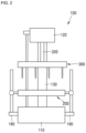
- FIGS. 1 and 2 are views illustrating a food texture measuring apparatus 1 according to an embodiment of the present invention.
- the food texture measuring apparatus 1 includes a frame 100, a stage module 200 on which a subject is put, and a probe module 300 that is placed on the stage module 200 and is displaceable.
- the frame 100 may include a base 110, a head 120 disposed on the base 110, and a neck 130 that connects the base 110 and the head 120 to each other and extends vertically.
- the frame 100 may have a U-shaped structure as a whole.
- a power device 140 may be built in the frame 100.
- the power device 140 is a device that can displace the probe module 300.
- the power device 140 may be, for example, a servo motor or the like, and the present invention is not limited thereto.
- the power device 140 is built in the head 120. However, the present invention is not limited thereto.
- the frame 100 may further include a guide beam 150 that is connected to the probe module 300 and guides displacement of the probe module 300.
- the guide beam 150 may include a beam connected between the base 110 and the head 120.
- the guide beam 150 may be an upright beam, and the present invention is not limited thereto.
- the frame 100 may further include a connection jig 160.
- the connection jig 160 may be an intermediate member that connects the stage module 200 and the base 110 to each other.
- the connection jig 160 may include a finger 162 that protrudes toward at least one side of the base 110, and a connection beam 164 that extends in the finger 162.
- the stage module 200 to be described later may be connected to the connection beam 164.
- connection jig 160 A specific embodiment of the connection jig 160 will be described in the description relating to the stage module 200 to be described later.
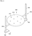
- FIGS. 3 and 4 are views illustrating the stage module 200 of the food texture measuring apparatus 1 according to an embodiment.
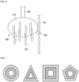
- FIG. 5 is a view illustrating the shape of the stage module 200 of the food texture measuring apparatus 1 according to an embodiment.
- the stage module 200 may include a stage plate 210 having a predetermined area. A subject that is a texture measurement target may be put on the stage plate 210.
- the stage plate 210 is a member having predetermined thickness and area.
- the material of the stage plate 210 is not limited and may include a synthetic resin or a metal material.
- the shape of the stage plate 210 may have various shapes according to texture patterns of the subject to be measured.
- the stage plate 210 may have a shape, such as a circle, a triangle, a square, or a pentagon, according to the arrangement of texture patterns of the subject.
- An example of the shape of the stage plate 210 described above is shown in FIG. 5 .
- the matters shown in the drawings are only examples, and the present invention is not limited thereto.
- One or more stage holes 212 penetrating the stage plate 210 vertically may be provided in the stage plate 210.
- stage holes 212 There may be a plurality of stage holes 212.
- the plurality of stage holes 212 may have an arbitrary arrangement according to texture patterns of the subject to be measured.
- the stage holes 212 may be arranged radially around the center of the probe plate 310, or may be respectively arranged at positions of vertices of a predetermined figure.
- At least one side of the stage plate 210 may be provided with a predetermined connection portion 220 connecting the frame 100 and the stage plate 210 to each other.
- the connection portion 220 may be connected to the connection beam 164 of the connection jig 160 described above.
- connection jig 160 and the connection portion 220 Connection between the connection jig 160 and the connection portion 220 and changing the size of the stage plate 210 thereby will be described as below.
- a plurality of connection jigs 160 may be provided in the frame 100, and a distance between the plurality of connection jigs 160 may be changed.
- the connection jig 160 may protrude from the base 110 in one direction, wherein a protruding width of the connection jig 160 may be changed.
- connection jig 160 may include a finger 162 that protrudes toward at least one side of the base 110, and a connection beam 164 that extends to the finger 162.
- the protruding width of the connection jig 160 is changed so that a distance between the connection beams 164 located on the finger 162 can be changed.
- the stage module 200 is connected to the connection jig 160. Specifically, the stage module 200 may be connected to the connection beam 164. In this case, the distance between the connection beams 164 is changed so that the size of the stage module 200 can be optionally changed.
- the stage module 200 having a large size may be connected to the connection jig 160.
- the texture of the subject having a large area can be measured.
- the stage module 200 having a small size can be connected to the connection jig 160.
- the texture of the subject having a small area can be measured.
- FIG. 6 is a view illustrating the probe module 300 of the food texture measuring apparatus 1 according to an embodiment of the present invention.
- FIG. 7 is a view illustrating an example of the arrangement of the probe module 300 of the food texture measuring apparatus according to an embodiment of the present invention.
- FIGS. 8 and 9 are views illustrating connection between the frame 100 and the probe module 300 of the food texture measuring apparatus 1 according to an embodiment of the present invention.
- FIG. 10 is a view illustrating the probe module 300 of the food texture measuring apparatus 1 according to an embodiment of the present invention.
- FIG. 11 is a view illustrating the relationship between the stage module 200 and the probe module 300 of the food texture measuring apparatus 1 according to an embodiment of the present invention.
- the probe module 300 may include the probe plate 310 having a predetermined area, pins 312 arranged on the bottom surface of the probe plate 310, and a connector 320 that connects the probe plate 310 and the power device 140 to each other.
- the probe plate 310 is a member having a predetermined thickness and area.
- the material of the probe plate 310 is not limited thereto and may include a synthetic resin or a metal material.
- the shape of the probe plate 310 may have various shapes according to texture patterns of the subject to be measured.
- the stage plate 210 may have a shape, such as a circle, a triangle, a square, or a pentagon, according to the arrangement of texture patterns of the subject.
- the pins 312 may be a predetermined sensor that is capable of measuring the texture of the subject.
- the pins 312 may measure the viscosity, moisture content, hardness, and the like of food that is the subject.
- the pins 312 may include an appropriate sensor unit.
- the present invention is not limited thereto.
- the pins 312 are arranged on the bottom surface of the probe plate 310.
- the pins 312 may be integrally connected to the probe plate 310.
- the pins 312 may be displaced integrally with the probe plate 310.
- the pins 312 descend together, and when the probe plate 310 ascends, the pins 312 may ascend together.
- the pins 312 may have various forms and shapes. That is, the shape of the pins 312 is not limited to the shape shown in the drawings.
- a plurality of pins 312 may be provided.
- the plurality of pins 312 may have an arbitrary arrangement.
- the plurality of pins 312 may have an arrangement according to established rules. In an example, a distance between the adjacent pins 312 may be the same. In another example, a plurality of pins 312 may have a predetermined polygonal or circular arrangement shape around the center of the probe plate 310. In addition, in another example, the plurality of pins 312 may have the polygonal or circular arrangement and may also have a multi-layered arrangement. For example, as shown in FIG. 7 , the probe module 300 may have a structure in which the pins 312 are arranged in an inner region of a relatively large polygon or circular shape (outer layer) and the pins 312 are arranged in an inner region of a relatively small polygon or circular shape (inner layer). However, the present invention is not limited thereto.
- a plurality of stage holes 212 may be provided in the stage module 200, and the arrangement of the plurality of stage holes 212 may be determined according to texture patterns of the subject to be measured.
- the pins 312 may be in plural, and a plurality of pins 312 may have an arrangement according to texture patterns of the subject to be measured. That is, the arrangement of the pins 312 and the arrangement of the stage holes 212 may correspond to each other.
- the pins 312 may be arranged radially around the center of the probe plate 310, or may also be respectively arranged at positions of vertices of a predetermined figure.
- the arrangement of the pins 312 may be determined according to texture patterns of the subject to the measured.
- the size of each of the pins 312 may be smaller than the size of each of the stage holes 212.
- the pins 312 may be put into the stage holes 212.
- the connector 320 may be connected to the probe plate 310 and may be a connection unit that connects the probe plate 310 and the frame 100 to each other.
- the connector 320 may be a predetermined beam that is located at the center of the probe plate 310 and extends vertically.
- a guide block 330 may be provided at one side of the probe plate 310.
- the guide block 330 may be a predetermined block connected to the guide beam 150 to be described below.
- the guide block 330 may be connected to the guide beam 150 and may be displaced along the guide beam 150.
- the guide block 330 may have guide holes through which the guide beam 150 passes.
- the guide block 330 and the guide beam 150 are provided so that the displacement of the probe module 300 can be stably guided.
- the probe module 300 may be connected to a head 120 of the frame 100.
- a connection position between the probe module 300 and the head 120 can be optionally changed.
- connection positions C1 and C2 between the probe module 300 and the head 120 may be relatively rear positions, as shown in FIG. 8 , and may be relatively front positions, as shown in FIG. 9 . That is, a distance between the central point of the probe module 300 and the neck 130 can be relatively changed.
- the probe module 300 having an appropriate size according to the size of the subject can be used.
- a unit and a method for changing the connection position of the probe module 300 are not limited thereto.
- a predetermined sliding device that changes the position of the probe module 300 in a state where the probe module 300 is connected to the head 120 may also be provided in the frame 100.
- a plurality of connection units e.g., screw holes or the like
- the probe module 300 may also be optionally connected to the plurality of connection units.
- the probe module 300 may include a predetermined linkage part 340 that connects the frame 300 and the connector 320 to each other. Furthermore, the connection position of the probe module 300 can be changed according to selection of the linkage part 340.
- the linkage part 340 may include a link block 342 having a plurality of connection holes 344 and 346 formed therein, and a connection screw 348 that connects the link block 342 to the head 120.
- the connector 320 may be connected to one of the connection holes 344 and 346.
- a connection end 322 having a predetermined male screw formed therein may be provided at an upper end of the connector 320.
- the connection screw 348 may pass through one connection hole 346 and may be connected to the head 120 of the frame 100.
- a connection position (accurately, the position of the connector 320) between the probe module 300 and the frame 100 may be changed.
- the probe module 300 may be located at an arbitrary position other than the center of the stage module 200.
- texture measurement of an arbitrary portion of the subject put on the stage module 200 can be performed.
- the probe module 300 may descend. In this case, when the pins 312 of the probe module 300 make contact with the subject, the texture of the subject can be measured. As described above, since the arrangement of the pins 312 is an arrangement corresponding to texture patterns of the subject, the texture patterns of the subject can be properly measured.
- the texture measuring apparatus 1 can be properly implemented according to the specifications of the subject.
- connection position of the probe module 300 may be different, texture measurement at several positions of the subject can be optionally performed.
- stage holes 212 are provided in the stage plate 210 of the stage module 200, and the stage holes 212 and the pins 312 may have an arrangement in which they correspond to each other. That is, the pins 312 and the stage holes 212 may be located in a straight line in a vertical direction with each other.
- an empty space is located under a texture measurement point (a point located directly below the pins 312) of the subject to be measured due to the stage holes 212.
- a texture measurement point a point located directly below the pins 312 of the subject to be measured due to the stage holes 212.
- resistance due to the stage plate 210 may not be received.
- the texture for example, the degree of elongation from when the pins 312 make contact until they penetrate
- the texture for example, the degree of elongation from when the pins 312 make contact until they penetrate
- the size of the pins 312 may be smaller than the size of the stage holes 212.
- the pins 312 can be put into the stage holes 212.
- a jamming phenomenon of the pins 312 may not occur.
- the texture of each position of food that is a subject can be simultaneously measured. Furthermore, the texture (e.g., changes in force from when the pins 312 make contact until they penetrate) of the subject can be accurately measured according to purposes.
- the food texture measuring apparatus and the food texture measuring method according to embodiments of the present invention may be properly used, in particular, in texture measurement of wide and flat food such as a pizza dough, for example.
- the pizza dough has a little viscosity (characteristics such as chewy, weeping or the like)
- the above-described properties can be effectively measured in a procedure in which, when the pins 312 make contact the pizza dough and penetrate the pizza dough, the pins 312 are put into the stage holes 212.
- FIG. 13 is a flowchart illustrating the order of a food texture measuring method by using a food texture measuring apparatus according to an embodiment of the present invention.
- the food texture measuring method according to an embodiment of the present invention is described as follows.
- First step first, the size of a subject is determined.
- the subject may be food having predetermined area and thickness, such as a pizza dough.
- the subject may be a product that can be cooked in a cooking appliance such as a microwave or an air fryer, and thus, preferably, may have a size acceptable in the cooking appliance.
- the subject may have a length of 3 to 10 inches.
- Second step a stage module 200 and a probe module 300 are selected according to the determined size of the subject. For example, when the size of the subject is large, the stage module 200 and the probe module 300 each having a large area can be selected.
- Third step the selected stage module 200 and probe module 300 are installed at the frame 100.
- the center of the stage module 200 and the center of the probe module 300 may be arranged to be positioned on a straight line with each other.
- the present invention is not necessarily limited thereto, and the probe module 300 is placed at one position of the stage module 200 so that the texture of an arbitrary part of the subject can also be measured.
- the probe module 300 includes a linkage part 340, and the position (a connection position between the probe module 300 and the head 120) of the probe module 300 can be optionally changed by the linkage part 340.
- the position of the probe module 300 can be changed by using the linkage part 340, and the probe module 300 can also be placed at an arbitrary position of the stage module 200.
- Fourth step the texture of the subject is measured.
- the stage module 200 includes a stage plate 210 having a predetermined area, and the stage plate 210 may include one or more stage holes 212 that penetrate the stage plate 210 vertically. Furthermore, the pins 312 may be located in the stage holes 212, and when the probe module 300 descends, the pins 312 may be put into the stage holes 212.
- the fourth step of measuring the texture of the subject a procedure in which the probe module 300 descends, the pins 312 penetrate the subject and are put into the stage holes 212, can be performed. According to this, the texture (changes in force from when the pins make contact until they penetrate) of the subject can be accurately measured according to purposes.
- the food texture measuring apparatus can be utilized in texture measurement of various food such as breads, confectionary, tortillas, and the like. Furthermore, when, as a result of performing measurement, data that do not meet the standard value are derived, factors (material, a mixing process, heating temperature and time, and the like) of the subject can be changed and supplemented. In addition, after changing these factors, texture can be measured again in the same environment (the use of the same probe) so that the accuracy of texture measurement can be enhanced. In addition, texture measurement can be conveniently performed for each area of the same food according to user's selection (configuration change and the like). Furthermore, according to texture measurement of these food and measurement results, the texture of each food can be optimized for distribution and cooking.
Landscapes
- Health & Medical Sciences (AREA)
- Life Sciences & Earth Sciences (AREA)
- Chemical & Material Sciences (AREA)
- Engineering & Computer Science (AREA)
- Food Science & Technology (AREA)
- Immunology (AREA)
- General Health & Medical Sciences (AREA)
- General Physics & Mathematics (AREA)
- Physics & Mathematics (AREA)
- Pathology (AREA)
- Biochemistry (AREA)
- Analytical Chemistry (AREA)
- Medicinal Chemistry (AREA)
- Investigating Or Analyzing Materials By The Use Of Ultrasonic Waves (AREA)
- Length Measuring Devices With Unspecified Measuring Means (AREA)
- Investigating Strength Of Materials By Application Of Mechanical Stress (AREA)
- General Preparation And Processing Of Foods (AREA)
Abstract
Description
- The present invention relates to a food texture measuring apparatus and a food texture measuring method, and more specifically to a food texture measuring apparatus which is capable of simultaneously measuring texture patterns of a subject and capable of measuring texture according to the size and shape of the subject.
- As a method for measuring the texture of food, there is a predetermined texture analysis apparatus. Such texture analysis apparatus can analyze the texture of various types of foods by using a variety of probes.
- Meanwhile, after food is cooked, textures may appear different from each other depending on the part. For example, in the case of pizza, the hardness of the texture may appear different according to the position of the pizza dough.
FIG. 11 shows texture of such a pizza dough, showing that the center has medium
strength, the sides have high strength, and a portion between the center and the sides (middle) has low strength. - Depending on these texture characteristics, the taste for food may change. Thus, food companies and food research institutes are conducting research to increase or decrease the difference in texture according to parts of food by improving raw materials and processing processes of food.
- In order to conduct such research, an apparatus capable of measuring texture characteristics quickly and accurately according to the size and shape of food is required.
-
Korean Patent Registration Laid-open Publication No. 10-2061419 - The present invention provides a food texture measuring module and a food texture measuring apparatus, which are capable of individually specifying texture of food according to sections and simultaneously measuring texture in one section so that a texture of food can be accurately and quickly measured.
- According to an aspect of the present invention, there is provided a food texture measuring apparatus including: a frame in which a power device is built; a stage module, which is connected to the frame and on which a subject is put; and a probe module, which is connected to the frame, located on the stage module and of which a position is changed, wherein the probe module includes: a probe plate having a predetermined area; pins arranged on a bottom surface of the probe plate; and a connector connecting the probe plate and the power device to each other, the probe plate and the pins are integrally displaced, and the pins are configured to measure texture of the subject put on the stage module.
- The frame may include: a base; a head disposed on the base; and a neck connecting the base and the head to each other and having a predetermined height, the stage module may be connected to the base, and the probe module may be connected to the head.
- The frame may include a guide beam extending in at least one direction, and the probe module may include a guide block connecting the probe plate and the guide beam to each other, and displacement of the probe module may be guided by the guide beam and the guide block.
- The probe module may be connected to the head, and a connection position of the probe module and the head may be optionally changed.
- The probe module may include a linkage part connecting the head and the connector to each other, and a position where the connector is connected to the linkage part and a position where the head is connected to the linkage part may be changed.
- The frame may include a connection jig connected to the base and protruding toward at least one side, a plurality of connection jigs may be provided, a distance between the plurality of connection jigs may be changed, the stage module may be connected to the connection jig, and a size of the stage module connected to the connection jig may be optionally changed according to the distance between the connection jigs.
- A plurality of pins may be provided, and the plurality of pins may have a predetermined arrangement according to texture patterns of food to be measured.
- The stage module may include a stage plate having a predetermined area, the stage plate may include one or more stage holes penetrating the stage plate vertically, the pins may be located in the stage holes, and, when the probe module descends, the pins may be capable of being put into the stage holes.
- According to another aspect of the present invention, there is provided a food texture measuring method by using a food texture measuring apparatus, the food texture measuring apparatus including a frame in which a power device is built; a stage module, which is connected to the frame and on which a subject is put; and a probe module, which is connected to the frame, located on the stage module and of which a position is changed, the food texture measuring method including: a first step of determining a size of a subject; a second step of selecting the stage module and the probe module; a third step of installing the selected stage module and probe module at the frame; and a fourth step of measuring texture of the subject.
- The third step may include arranging the stage module and the probe module so that a center of the stage module and a center of the probe module are arranged to be positioned on a straight line with each other.
- The probe module may include: a probe plate having a predetermined area; and pins arranged on a bottom surface of the probe plate, the stage module may include a stage plate having a predetermined area, the stage plate may include one or more stage holes penetrating the stage plate vertically, the pins may be located in the stage holes, and, when the probe module descends, the pins may be capable of being put into the stage holes, and the fourth step may include lowering the probe module and allowing the pins to penetrate the subject and the pins to be put into the stage holes.
- The probe module may include: a probe plate having a predetermined area; pins arranged on a bottom surface of the probe plate; a connector connecting the probe plate and the power device to each other; and a linkage part connecting the head and the connector to each other, the linkage part may be configured in such a way that a position where the connector is connected to the linkage part and a position where the head is connected to the linkage part may be changed, and the third step may include changing a position of the probe module by using the linkage part.
- According to an embodiment of the present invention, since the arrangement of pins is an arrangement corresponding to texture patterns of a subject, texture patterns of the subject can be appropriately measured.
- In addition, since the size and shape of a stage module and the size, shape, and position of a probe module can be changed, a texture measuring apparatus can be properly implemented according to the specifications of the subject.
- In addition, a stage hole is provided in a stage plate of the stage module, and the stage hole and the pins may have arrangements corresponding to each other. According to this, an empty space due to the stage hole is located below a texture measurement point (a point where the subject is in contact with the pins) of the subject to be measured. Thus, when the texture of food is measured by the pin, resistance due to the stage plate may not be encountered. For example, as the probe module located on the stage module descends, an examination environment in which the pins penetrate the subject can be created. Thus, the texture of the subject (variation in force from contact with the pins to penetration) can be accurately measured according to the purpose.
-
-
FIGS. 1 and2 are views illustrating a food texture measuring apparatus according to an embodiment of the present invention. -
FIGS. 3 and4 are views illustrating a stage module of a food texture measuring apparatus according to an embodiment of the present invention. -
FIG. 5 is a view illustrating the shape of a stage module of a food texture measuring apparatus according to an embodiment of the present invention. -
FIG. 6 is a view illustrating a probe module of a food texture measuring apparatus according to an embodiment of the present invention. -
FIG. 7 is a view illustrating an example of the arrangement of a probe module of a food texture measuring apparatus according to an embodiment of the present invention. -
FIGS. 8 and 9 are views illustrating connection between a frame and a probe module of a food texture measuring apparatus according to an embodiment of the present invention. -
FIG. 10 is a view illustrating a probe module of a food texture measuring apparatus according to an embodiment of the present invention. -
FIG. 11 is a view illustrating the relationship between a stage module and a probe module of a food texture measuring apparatus according to an embodiment of the present invention. -
FIG. 12 is a view illustrating an example of a texture of a pizza dough. -
FIG. 13 is a flowchart illustrating the order of a food texture measuring method by using a food texture measuring apparatus according to an embodiment of the present invention. - Hereinafter, the present invention will be described in detail by describing embodiments of the present invention with reference to the accompanying drawings.
-
FIGS. 1 and2 are views illustrating a food texture measuringapparatus 1 according to an embodiment of the present invention. - The food texture measuring
apparatus 1 according to an embodiment of the present invention includes aframe 100, astage module 200 on which a subject is put, and aprobe module 300 that is placed on thestage module 200 and is displaceable. - According to an embodiment, the
frame 100 may include abase 110, ahead 120 disposed on thebase 110, and aneck 130 that connects thebase 110 and thehead 120 to each other and extends vertically. Thus, theframe 100 may have a U-shaped structure as a whole. - A
power device 140 may be built in theframe 100. Thepower device 140 is a device that can displace theprobe module 300. Thepower device 140 may be, for example, a servo motor or the like, and the present invention is not limited thereto. InFIG. 1 , thepower device 140 is built in thehead 120. However, the present invention is not limited thereto. - According to an embodiment, the
frame 100 may further include aguide beam 150 that is connected to theprobe module 300 and guides displacement of theprobe module 300. - In an example, the
guide beam 150 may include a beam connected between thebase 110 and thehead 120. Theguide beam 150 may be an upright beam, and the present invention is not limited thereto. - According to an embodiment, the
frame 100 may further include aconnection jig 160. Theconnection jig 160 may be an intermediate member that connects thestage module 200 and thebase 110 to each other. According to an embodiment, theconnection jig 160 may include afinger 162 that protrudes toward at least one side of thebase 110, and aconnection beam 164 that extends in thefinger 162. Thestage module 200 to be described later may be connected to theconnection beam 164. - A specific embodiment of the
connection jig 160 will be described in the description relating to thestage module 200 to be described later. -
FIGS. 3 and4 are views illustrating thestage module 200 of the foodtexture measuring apparatus 1 according to an embodiment.FIG. 5 is a view illustrating the shape of thestage module 200 of the foodtexture measuring apparatus 1 according to an embodiment. - The
stage module 200 may include astage plate 210 having a predetermined area. A subject that is a texture measurement target may be put on thestage plate 210. - The
stage plate 210 is a member having predetermined thickness and area. The material of thestage plate 210 is not limited and may include a synthetic resin or a metal material. - The shape of the
stage plate 210 may have various shapes according to texture patterns of the subject to be measured. For example, thestage plate 210 may have a shape, such as a circle, a triangle, a square, or a pentagon, according to the arrangement of texture patterns of the subject. An example of the shape of thestage plate 210 described above is shown inFIG. 5 . However, the matters shown in the drawings are only examples, and the present invention is not limited thereto. - One or more stage holes 212 penetrating the
stage plate 210 vertically may be provided in thestage plate 210. - There may be a plurality of stage holes 212. The plurality of stage holes 212 may have an arbitrary arrangement according to texture patterns of the subject to be measured.
- For example, the stage holes 212 may be arranged radially around the center of the
probe plate 310, or may be respectively arranged at positions of vertices of a predetermined figure. - According to an embodiment, at least one side of the
stage plate 210 may be provided with apredetermined connection portion 220 connecting theframe 100 and thestage plate 210 to each other. Specifically, theconnection portion 220 may be connected to theconnection beam 164 of theconnection jig 160 described above. - Connection between the
connection jig 160 and theconnection portion 220 and changing the size of thestage plate 210 thereby will be described as below. - According to an embodiment, a plurality of connection jigs 160 may be provided in the
frame 100, and a distance between the plurality of connection jigs 160 may be changed. For example, as the arrow A shown inFIGS. 3 and4 , theconnection jig 160 may protrude from the base 110 in one direction, wherein a protruding width of theconnection jig 160 may be changed. - For example, according to an embodiment, the
connection jig 160 may include afinger 162 that protrudes toward at least one side of thebase 110, and aconnection beam 164 that extends to thefinger 162. The protruding width of theconnection jig 160 is changed so that a distance between the connection beams 164 located on thefinger 162 can be changed. - The
stage module 200 is connected to theconnection jig 160. Specifically, thestage module 200 may be connected to theconnection beam 164. In this case, the distance between the connection beams 164 is changed so that the size of thestage module 200 can be optionally changed. - For example, as shown in
FIG. 4 , when the distance between the connection beams 164 is set to be relatively large, thestage module 200 having a large size may be connected to theconnection jig 160. Thus, the texture of the subject having a large area can be measured. In contrast, when the distance between the connection beams 164 is set to be relatively small, as shown inFIG. 3 , thestage module 200 having a small size can be connected to theconnection jig 160. Thus, the texture of the subject having a small area can be measured. -
FIG. 6 is a view illustrating theprobe module 300 of the foodtexture measuring apparatus 1 according to an embodiment of the present invention.FIG. 7 is a view illustrating an example of the arrangement of theprobe module 300 of the food texture measuring apparatus according to an embodiment of the present invention.FIGS. 8 and 9 are views illustrating connection between theframe 100 and theprobe module 300 of the foodtexture measuring apparatus 1 according to an embodiment of the present invention.FIG. 10 is a view illustrating theprobe module 300 of the foodtexture measuring apparatus 1 according to an embodiment of the present invention.FIG. 11 is a view illustrating the relationship between thestage module 200 and theprobe module 300 of the foodtexture measuring apparatus 1 according to an embodiment of the present invention. - The
probe module 300 may include theprobe plate 310 having a predetermined area, pins 312 arranged on the bottom surface of theprobe plate 310, and aconnector 320 that connects theprobe plate 310 and thepower device 140 to each other. - The
probe plate 310 is a member having a predetermined thickness and area. The material of theprobe plate 310 is not limited thereto and may include a synthetic resin or a metal material. - The shape of the
probe plate 310 may have various shapes according to texture patterns of the subject to be measured. For example, thestage plate 210 may have a shape, such as a circle, a triangle, a square, or a pentagon, according to the arrangement of texture patterns of the subject. - The
pins 312 may be a predetermined sensor that is capable of measuring the texture of the subject. For example, thepins 312 may measure the viscosity, moisture content, hardness, and the like of food that is the subject. In order to measure such a texture, thepins 312 may include an appropriate sensor unit. However, the present invention is not limited thereto. - The
pins 312 are arranged on the bottom surface of theprobe plate 310. Thepins 312 may be integrally connected to theprobe plate 310. Thus, when theprobe plate 310 is displaced, thepins 312 may be displaced integrally with theprobe plate 310. For example, when theprobe plate 310 descends, thepins 312 descend together, and when theprobe plate 310 ascends, thepins 312 may ascend together. - The
pins 312 may have various forms and shapes. That is, the shape of thepins 312 is not limited to the shape shown in the drawings. - A plurality of
pins 312 may be provided. The plurality ofpins 312 may have an arbitrary arrangement. - According to an embodiment, the plurality of
pins 312 may have an arrangement according to established rules. In an example, a distance between theadjacent pins 312 may be the same. In another example, a plurality ofpins 312 may have a predetermined polygonal or circular arrangement shape around the center of theprobe plate 310. In addition, in another example, the plurality ofpins 312 may have the polygonal or circular arrangement and may also have a multi-layered arrangement. For example, as shown inFIG. 7 , theprobe module 300 may have a structure in which thepins 312 are arranged in an inner region of a relatively large polygon or circular shape (outer layer) and thepins 312 are arranged in an inner region of a relatively small polygon or circular shape (inner layer). However, the present invention is not limited thereto. - As described above, a plurality of stage holes 212 may be provided in the
stage module 200, and the arrangement of the plurality of stage holes 212 may be determined according to texture patterns of the subject to be measured. In response, thepins 312 may be in plural, and a plurality ofpins 312 may have an arrangement according to texture patterns of the subject to be measured. That is, the arrangement of thepins 312 and the arrangement of the stage holes 212 may correspond to each other. - For example, the
pins 312 may be arranged radially around the center of theprobe plate 310, or may also be respectively arranged at positions of vertices of a predetermined figure. The arrangement of thepins 312 may be determined according to texture patterns of the subject to the measured. - In this case, according to an embodiment, the size of each of the
pins 312 may be smaller than the size of each of the stage holes 212. Thus, thepins 312 may be put into the stage holes 212. - The
connector 320 may be connected to theprobe plate 310 and may be a connection unit that connects theprobe plate 310 and theframe 100 to each other. For example, theconnector 320 may be a predetermined beam that is located at the center of theprobe plate 310 and extends vertically. - According to an embodiment, a
guide block 330 may be provided at one side of theprobe plate 310. Theguide block 330 may be a predetermined block connected to theguide beam 150 to be described below. - The
guide block 330 may be connected to theguide beam 150 and may be displaced along theguide beam 150. For example, theguide block 330 may have guide holes through which theguide beam 150 passes. - As described above, the
guide block 330 and theguide beam 150 are provided so that the displacement of theprobe module 300 can be stably guided. - According to an embodiment, the
probe module 300 may be connected to ahead 120 of theframe 100. In this case, a connection position between theprobe module 300 and thehead 120 can be optionally changed. - For example, when a position where a
neck 130 of theframe 100 is located, is referred to as rear, connection positions C1 and C2 between theprobe module 300 and thehead 120 may be relatively rear positions, as shown inFIG. 8 , and may be relatively front positions, as shown inFIG. 9 . That is, a distance between the central point of theprobe module 300 and theneck 130 can be relatively changed. - Thus, when the area of the subject is large and the size of the
probe plate 310 provided in theprobe module 300 is set to be large, the distance between theneck 130 and the center point of theprobe module 300 can be increased. Thus, theprobe module 300 having an appropriate size according to the size of the subject can be used. - A unit and a method for changing the connection position of the
probe module 300 are not limited thereto. For example, a predetermined sliding device that changes the position of theprobe module 300 in a state where theprobe module 300 is connected to thehead 120, may also be provided in theframe 100. Alternatively, a plurality of connection units (e.g., screw holes or the like) may be provided in thehead 120, and theprobe module 300 may also be optionally connected to the plurality of connection units. - According to an embodiment, the
probe module 300 may include apredetermined linkage part 340 that connects theframe 300 and theconnector 320 to each other. Furthermore, the connection position of theprobe module 300 can be changed according to selection of thelinkage part 340. - For example, as shown in
FIG. 10 , thelinkage part 340 may include alink block 342 having a plurality of connection holes 344 and 346 formed therein, and aconnection screw 348 that connects thelink block 342 to thehead 120. Theconnector 320 may be connected to one of the connection holes 344 and 346. In an example, aconnection end 322 having a predetermined male screw formed therein may be provided at an upper end of theconnector 320. Furthermore, theconnection screw 348 may pass through oneconnection hole 346 and may be connected to thehead 120 of theframe 100. Thus, a connection position (accurately, the position of the connector 320) between theprobe module 300 and theframe 100 may be changed. - According to an embodiment, the
probe module 300 may be located at an arbitrary position other than the center of thestage module 200. Thus, texture measurement of an arbitrary portion of the subject put on thestage module 200 can be performed. - Hereinafter, the operation and effects of the food
texture measuring apparatus 1 according to the present invention will be described. - In a state where the subject is put on the
stage module 200, theprobe module 300 may descend. In this case, when thepins 312 of theprobe module 300 make contact with the subject, the texture of the subject can be measured. As described above, since the arrangement of thepins 312 is an arrangement corresponding to texture patterns of the subject, the texture patterns of the subject can be properly measured. - In addition, since the size and shape of the
stage module 200 and the size, shape, and position of theprobe module 300 can be changed, thetexture measuring apparatus 1 can be properly implemented according to the specifications of the subject. - In addition, since the connection position of the
probe module 300 may be different, texture measurement at several positions of the subject can be optionally performed. - In addition, the stage holes 212 are provided in the
stage plate 210 of thestage module 200, and the stage holes 212 and thepins 312 may have an arrangement in which they correspond to each other. That is, thepins 312 and the stage holes 212 may be located in a straight line in a vertical direction with each other. - According to this, an empty space is located under a texture measurement point (a point located directly below the pins 312) of the subject to be measured due to the stage holes 212. Thus, when the texture of food is measured by the
pins 312, resistance due to thestage plate 210 may not be received. For example, as theprobe module 300 located on thestage module 200 descends, an inspection environment in which thepins 312 penetrate the subject, may be established. According to this, the texture (for example, the degree of elongation from when thepins 312 make contact until they penetrate) of the subject can be accurately measured according to purposes. - In addition, in this case, according to an embodiment, the size of the
pins 312 may be smaller than the size of the stage holes 212. Thus, when thepins 312 drop, thepins 312 can be put into the stage holes 212. Thus, a jamming phenomenon of thepins 312 may not occur. - In a food texture measuring method by using a food texture measuring apparatus according to the present invention, the texture of each position of food that is a subject can be simultaneously measured. Furthermore, the texture (e.g., changes in force from when the
pins 312 make contact until they penetrate) of the subject can be accurately measured according to purposes. - The food texture measuring apparatus and the food texture measuring method according to embodiments of the present invention may be properly used, in particular, in texture measurement of wide and flat food such as a pizza dough, for example. In particular, since the pizza dough has a little viscosity (characteristics such as chewy, weeping or the like), the above-described properties can be effectively measured in a procedure in which, when the
pins 312 make contact the pizza dough and penetrate the pizza dough, thepins 312 are put into the stage holes 212. -
FIG. 13 is a flowchart illustrating the order of a food texture measuring method by using a food texture measuring apparatus according to an embodiment of the present invention. - Hereinafter, the food texture measuring method according to an embodiment of the present invention will be described.
- The food texture measuring method according to an embodiment of the present invention is described as follows.
- First step: first, the size of a subject is determined. The subject may be food having predetermined area and thickness, such as a pizza dough. Meanwhile, the subject may be a product that can be cooked in a cooking appliance such as a microwave or an air fryer, and thus, preferably, may have a size acceptable in the cooking appliance. In an example, the subject may have a length of 3 to 10 inches.
- Second step: a
stage module 200 and aprobe module 300 are selected according to the determined size of the subject. For example, when the size of the subject is large, thestage module 200 and theprobe module 300 each having a large area can be selected. - Third step: the selected
stage module 200 andprobe module 300 are installed at theframe 100. - In this case, the center of the
stage module 200 and the center of theprobe module 300 may be arranged to be positioned on a straight line with each other. Meanwhile, according to another embodiment, the present invention is not necessarily limited thereto, and theprobe module 300 is placed at one position of thestage module 200 so that the texture of an arbitrary part of the subject can also be measured. - In this case, according to an embodiment, the
probe module 300 includes alinkage part 340, and the position (a connection position between theprobe module 300 and the head 120) of theprobe module 300 can be optionally changed by thelinkage part 340. Thus, the position of theprobe module 300 can be changed by using thelinkage part 340, and theprobe module 300 can also be placed at an arbitrary position of thestage module 200. - Fourth step: the texture of the subject is measured.
- In this case, the
stage module 200 includes astage plate 210 having a predetermined area, and thestage plate 210 may include one or more stage holes 212 that penetrate thestage plate 210 vertically. Furthermore, thepins 312 may be located in the stage holes 212, and when theprobe module 300 descends, thepins 312 may be put into the stage holes 212. - Thus, in the fourth step of measuring the texture of the subject, a procedure in which the
probe module 300 descends, thepins 312 penetrate the subject and are put into the stage holes 212, can be performed. According to this, the texture (changes in force from when the pins make contact until they penetrate) of the subject can be accurately measured according to purposes. - The food texture measuring apparatus according to an embodiment of the present invention can be utilized in texture measurement of various food such as breads, confectionary, tortillas, and the like. Furthermore, when, as a result of performing measurement, data that do not meet the standard value are derived, factors (material, a mixing process, heating temperature and time, and the like) of the subject can be changed and supplemented. In addition, after changing these factors, texture can be measured again in the same environment (the use of the same probe) so that the accuracy of texture measurement can be enhanced. In addition, texture measurement can be conveniently performed for each area of the same food according to user's selection (configuration change and the like). Furthermore, according to texture measurement of these food and measurement results, the texture of each food can be optimized for distribution and cooking.
- While the present invention has been particularly shown and described with reference to exemplary embodiments thereof, it will be understood by those of ordinary skill in the art that various changes in form and details may be made therein without departing from the spirit and scope of the present invention as defined by the following claims.
-
- 1: food texture measuring apparatus
- 100: frame
- 110: base
- 120: head
- 130: neck
- 140: power device
- 150: guide beam
- 160: connection jig
- 162: finger
- 164: connection beam
- 200: stage module
- 210: stage plate
- 212: stage holes
- 220: connection portion
- 300: probe module
- 310: probe plate
- 312: pins
- 320: connector
- 322: connection end
- 330: guide block
- 340: linkage part
- 342: link block
- 344,346: connection hole
- 348: connection screw
Claims (12)
- A food texture measuring apparatus comprising:a frame in which a power device is built;a stage module, which is connected to the frame and on which a subject is put; anda probe module, which is connected to the frame, located on the stage module and of which a position is changed,wherein the probe module comprises:a probe plate having a predetermined area;pins arranged on a bottom surface of the probe plate; anda connector connecting the probe plate and the power device to each other,the probe plate and the pins are integrally displaced, andthe pins are configured to measure texture of the subject put on the stage module.
- The food texture measuring apparatus of claim 1, wherein the frame comprises:a base;a head disposed on the base; anda neck connecting the base and the head to each other and having a predetermined height,the stage module is connected to the base, andthe probe module is connected to the head.
- The food texture measuring apparatus of claim 1, wherein the frame comprises a guide beam extending in at least one direction, the probe module comprises a guide block connecting the probe plate and the guide beam to each other, and displacement of the probe module is guided by the guide beam and the guide block.
- The food texture measuring apparatus of claim 2, wherein the probe module is connected to the head, and a connection position of the probe module and the head is optionally changed.
- The food texture measuring apparatus of claim 4, wherein the probe module comprises a linkage part connecting the head and the connector to each other, and a position where the connector is connected to the linkage part and a position where the head is connected to the linkage part are changed.
- The food texture measuring apparatus of claim 2, wherein the frame comprises a connection jig connected to the base and protruding toward at least one side, a plurality of connection jigs are provided, a distance between the plurality of connection jigs is changed, the stage module is connected to the connection jig, and a size of the stage module connected to the connection jig is optionally changed according to the distance between the connection jigs.
- The food texture measuring apparatus of claim 1, wherein a plurality of pins are provided, and the plurality of pins have a predetermined arrangement according to texture patterns of food to be measured.
- The food texture measuring apparatus of claim 1, wherein the stage module comprises a stage plate having a predetermined area, the stage plate comprises one or more stage holes penetrating the stage plate vertically, and the pins are located in the stage holes, and, when the probe module descends, the pins are capable of being put into the stage holes.
- A food texture measuring method by using a food texture measuring apparatus, the food texture measuring apparatus including a frame in which a power device is built; a stage module, which is connected to the frame and on which a subject is put; and a probe module, which is connected to the frame, is located on the stage module and of which position is changed, the food texture measuring method comprising:a first step of determining a size of a subject;a second step of selecting the stage module and the probe module;a third step of installing the selected stage module and probe module at the frame; anda fourth step of measuring texture of the subject.
- The food texture measuring method of claim 9, wherein the third step comprises arranging the stage module and the probe module so that a center of the stage module and a center of the probe module are arranged to be positioned on a straight line with each other.
- The food texture measuring method of claim 9, wherein the probe module comprises:a probe plate having a predetermined area; andpins arranged on a bottom surface of the probe plate,the stage module comprises a stage plate having a predetermined area, the stage plate comprises one or more stage holes penetrating the stage plate vertically, the pins are located in the stage holes, and, when the probe module descends, the pins are capable of being put into the stage holes, andthe fourth step comprises lowering the probe module and allowing the pins to penetrate the subject and the pins to be put into the stage holes.
- The food texture measuring method of claim 9, wherein the probe module comprises:a probe plate having a predetermined area;pins arranged on a bottom surface of the probe plate;a connector connecting the probe plate and the power device to each other; anda linkage part connecting the head and the connector to each other,the linkage part is configured in such a way that a position where the connector is connected to the linkage part and a position where the head is connected to the linkage part are changed, andthe third step comprises changing a position of the probe module by using the linkage part.
Applications Claiming Priority (2)
| Application Number | Priority Date | Filing Date | Title |
|---|---|---|---|
| KR1020210169439A KR102789295B1 (en) | 2021-11-30 | 2021-11-30 | Texture measuring apparatus and texture measuring method |
| PCT/KR2022/017558 WO2023101249A1 (en) | 2021-11-30 | 2022-11-09 | Food texture measuring apparatus and food texture measuring method |
Publications (2)
| Publication Number | Publication Date |
|---|---|
| EP4332570A1 true EP4332570A1 (en) | 2024-03-06 |
| EP4332570A4 EP4332570A4 (en) | 2024-10-30 |
Family
ID=86612530
Family Applications (1)
| Application Number | Title | Priority Date | Filing Date |
|---|---|---|---|
| EP22901607.6A Pending EP4332570A4 (en) | 2021-11-30 | 2022-11-09 | DEVICE AND METHOD FOR MEASURING FOOD TEXTURE |
Country Status (7)
| Country | Link |
|---|---|
| US (1) | US20240319158A1 (en) |
| EP (1) | EP4332570A4 (en) |
| JP (1) | JP7690069B2 (en) |
| KR (1) | KR102789295B1 (en) |
| CN (1) | CN117546021A (en) |
| AU (1) | AU2022401334B2 (en) |
| WO (1) | WO2023101249A1 (en) |
Family Cites Families (9)
| Publication number | Priority date | Publication date | Assignee | Title |
|---|---|---|---|---|
| US3732727A (en) * | 1971-12-07 | 1973-05-15 | Us Army | Method and apparatus for testing the tenderness of meat |
| US4007632A (en) * | 1976-01-29 | 1977-02-15 | The United States Of America As Represented By The Secretary Of The Army | Apparatus for determining the textural qualities of food |
| EP1219947B1 (en) * | 2000-12-20 | 2006-10-18 | Consismetric S.A. | Method for penetrometrically measuring the consistency of substances and apparatus for the application of the method |
| CN100344168C (en) * | 2003-07-17 | 2007-10-17 | 华为技术有限公司 | Method for ensuring consistency during context deleting of packet data protocol |
| JP6375178B2 (en) * | 2014-08-26 | 2018-08-15 | 国立大学法人広島大学 | Balance type texture measuring device |
| JP6723633B2 (en) * | 2015-12-10 | 2020-07-15 | 株式会社ディスコ | Inspection equipment |
| CN207557231U (en) * | 2017-12-27 | 2018-06-29 | 广东新供销天润粮油集团有限公司 | Texture instrument |
| KR102061419B1 (en) | 2018-06-29 | 2019-12-31 | 강원대학교산학협력단 | Removable Repetitive Measuring Apparatus for texture of food |
| EP4036568B1 (en) * | 2021-01-28 | 2025-12-31 | Tata Consultancy Services Limited | METHOD AND SYSTEM FOR DETERMINING THE VISCOSITY INFORMATION OF FLUIDS |
-
2021
- 2021-11-30 KR KR1020210169439A patent/KR102789295B1/en active Active
-
2022
- 2022-11-09 JP JP2023577270A patent/JP7690069B2/en active Active
- 2022-11-09 CN CN202280044562.9A patent/CN117546021A/en active Pending
- 2022-11-09 WO PCT/KR2022/017558 patent/WO2023101249A1/en not_active Ceased
- 2022-11-09 US US18/577,144 patent/US20240319158A1/en active Pending
- 2022-11-09 EP EP22901607.6A patent/EP4332570A4/en active Pending
- 2022-11-09 AU AU2022401334A patent/AU2022401334B2/en active Active
Also Published As
| Publication number | Publication date |
|---|---|
| WO2023101249A1 (en) | 2023-06-08 |
| AU2022401334A1 (en) | 2023-12-14 |
| EP4332570A4 (en) | 2024-10-30 |
| US20240319158A1 (en) | 2024-09-26 |
| KR20230081403A (en) | 2023-06-07 |
| AU2022401334B2 (en) | 2025-08-28 |
| JP7690069B2 (en) | 2025-06-09 |
| JP2024522711A (en) | 2024-06-21 |
| CN117546021A (en) | 2024-02-09 |
| KR102789295B1 (en) | 2025-04-01 |
Similar Documents
| Publication | Publication Date | Title |
|---|---|---|
| US10520458B2 (en) | Identification method for electrochemical test strips | |
| US20240319158A1 (en) | Food texture measuring apparatus and food texture measuring method | |
| US6250147B1 (en) | Device and method for analyzing starch-containing product | |
| WO2015045222A1 (en) | Inspection system, inspection method, and readable recording medium | |
| TW487607B (en) | Apparatus for measuring conformance of a manufactured food product | |
| WO2006073736A2 (en) | Probe head arrays | |
| CN109507055B (en) | Method for measuring hardness distribution of fastener | |
| JPH05273237A (en) | Probe card | |
| JP2006226735A (en) | Edible oil deterioration degree evaluation method and edible oil deterioration degree evaluation device | |
| KR20020025786A (en) | Calibration Device for Semiconductor Testing Apparatus, Calibration Method and Semiconductor Testing Apparatus | |
| KR101027332B1 (en) | Egg white height measuring device and measuring method using the same | |
| Bourne | Texture measurements on finished baked goods | |
| KR102514508B1 (en) | Atomic layer deposition apparatus and atomic layer deposition method | |
| JP2003302437A (en) | Substrate inspection method and substrate inspection device | |
| CN208155189U (en) | A kind of hole location detecting cubing based on Different Plane | |
| JP2005049314A (en) | Probing test method and probe state detection device | |
| CN117268965B (en) | Texture analyzer, sample slot thereof, and sample hardness testing method | |
| CN209706778U (en) | Elastic slice height detecting device | |
| CN217238212U (en) | Electronic component measuring value device | |
| CN115164803B (en) | Method for rapidly calculating copper thickness of PCB (printed circuit board) | |
| KR200214606Y1 (en) | Jig for semiconductor package lead inspection | |
| JP2001153773A (en) | Measuring machine for deflection temperature under load | |
| CN206756032U (en) | One kind selects gear shift housing detecting tool | |
| JPH09127037A (en) | Apparatus and method for quality control of food | |
| CN118330430A (en) | Embedded coil panel inductance testing device |
Legal Events
| Date | Code | Title | Description |
|---|---|---|---|
| STAA | Information on the status of an ep patent application or granted ep patent |
Free format text: STATUS: THE INTERNATIONAL PUBLICATION HAS BEEN MADE |
|
| PUAI | Public reference made under article 153(3) epc to a published international application that has entered the european phase |
Free format text: ORIGINAL CODE: 0009012 |
|
| STAA | Information on the status of an ep patent application or granted ep patent |
Free format text: STATUS: REQUEST FOR EXAMINATION WAS MADE |
|
| 17P | Request for examination filed |
Effective date: 20231129 |
|
| AK | Designated contracting states |
Kind code of ref document: A1 Designated state(s): AL AT BE BG CH CY CZ DE DK EE ES FI FR GB GR HR HU IE IS IT LI LT LU LV MC ME MK MT NL NO PL PT RO RS SE SI SK SM TR |
|
| A4 | Supplementary search report drawn up and despatched |
Effective date: 20240926 |
|
| RIC1 | Information provided on ipc code assigned before grant |
Ipc: G01N 33/02 20060101AFI20240920BHEP |
|
| DAV | Request for validation of the european patent (deleted) | ||
| DAX | Request for extension of the european patent (deleted) |