EP4332526A1 - Temperature measuring device and temperature measuring method - Google Patents
Temperature measuring device and temperature measuring method Download PDFInfo
- Publication number
- EP4332526A1 EP4332526A1 EP21944144.1A EP21944144A EP4332526A1 EP 4332526 A1 EP4332526 A1 EP 4332526A1 EP 21944144 A EP21944144 A EP 21944144A EP 4332526 A1 EP4332526 A1 EP 4332526A1
- Authority
- EP
- European Patent Office
- Prior art keywords
- image
- target
- thermal infrared
- unit
- distance
- Prior art date
- Legal status (The legal status is an assumption and is not a legal conclusion. Google has not performed a legal analysis and makes no representation as to the accuracy of the status listed.)
- Granted
Links
Images







Classifications
-
- G—PHYSICS
- G01—MEASURING; TESTING
- G01J—MEASUREMENT OF INTENSITY, VELOCITY, SPECTRAL CONTENT, POLARISATION, PHASE OR PULSE CHARACTERISTICS OF INFRARED, VISIBLE OR ULTRAVIOLET LIGHT; COLORIMETRY; RADIATION PYROMETRY
- G01J5/00—Radiation pyrometry, e.g. infrared or optical thermometry
- G01J5/48—Thermography; Techniques using wholly visual means
-
- H—ELECTRICITY
- H04—ELECTRIC COMMUNICATION TECHNIQUE
- H04N—PICTORIAL COMMUNICATION, e.g. TELEVISION
- H04N23/00—Cameras or camera modules comprising electronic image sensors; Control thereof
- H04N23/20—Cameras or camera modules comprising electronic image sensors; Control thereof for generating image signals from infrared radiation only
- H04N23/23—Cameras or camera modules comprising electronic image sensors; Control thereof for generating image signals from infrared radiation only from thermal infrared radiation
-
- G—PHYSICS
- G01—MEASURING; TESTING
- G01J—MEASUREMENT OF INTENSITY, VELOCITY, SPECTRAL CONTENT, POLARISATION, PHASE OR PULSE CHARACTERISTICS OF INFRARED, VISIBLE OR ULTRAVIOLET LIGHT; COLORIMETRY; RADIATION PYROMETRY
- G01J5/00—Radiation pyrometry, e.g. infrared or optical thermometry
- G01J5/0022—Radiation pyrometry, e.g. infrared or optical thermometry for sensing the radiation of moving bodies
- G01J5/0025—Living bodies
-
- G—PHYSICS
- G01—MEASURING; TESTING
- G01J—MEASUREMENT OF INTENSITY, VELOCITY, SPECTRAL CONTENT, POLARISATION, PHASE OR PULSE CHARACTERISTICS OF INFRARED, VISIBLE OR ULTRAVIOLET LIGHT; COLORIMETRY; RADIATION PYROMETRY
- G01J5/00—Radiation pyrometry, e.g. infrared or optical thermometry
- G01J5/02—Constructional details
- G01J5/026—Control of working procedures of a pyrometer, other than calibration; Bandwidth calculation; Gain control
-
- G—PHYSICS
- G01—MEASURING; TESTING
- G01J—MEASUREMENT OF INTENSITY, VELOCITY, SPECTRAL CONTENT, POLARISATION, PHASE OR PULSE CHARACTERISTICS OF INFRARED, VISIBLE OR ULTRAVIOLET LIGHT; COLORIMETRY; RADIATION PYROMETRY
- G01J5/00—Radiation pyrometry, e.g. infrared or optical thermometry
- G01J5/02—Constructional details
- G01J5/0275—Control or determination of height or distance or angle information for sensors or receivers
-
- G—PHYSICS
- G01—MEASURING; TESTING
- G01J—MEASUREMENT OF INTENSITY, VELOCITY, SPECTRAL CONTENT, POLARISATION, PHASE OR PULSE CHARACTERISTICS OF INFRARED, VISIBLE OR ULTRAVIOLET LIGHT; COLORIMETRY; RADIATION PYROMETRY
- G01J5/00—Radiation pyrometry, e.g. infrared or optical thermometry
- G01J5/02—Constructional details
- G01J5/08—Optical arrangements
- G01J5/0859—Sighting arrangements, e.g. cameras
-
- G—PHYSICS
- G01—MEASURING; TESTING
- G01J—MEASUREMENT OF INTENSITY, VELOCITY, SPECTRAL CONTENT, POLARISATION, PHASE OR PULSE CHARACTERISTICS OF INFRARED, VISIBLE OR ULTRAVIOLET LIGHT; COLORIMETRY; RADIATION PYROMETRY
- G01J5/00—Radiation pyrometry, e.g. infrared or optical thermometry
- G01J5/02—Constructional details
- G01J5/08—Optical arrangements
- G01J5/0896—Optical arrangements using a light source, e.g. for illuminating a surface
-
- G—PHYSICS
- G01—MEASURING; TESTING
- G01J—MEASUREMENT OF INTENSITY, VELOCITY, SPECTRAL CONTENT, POLARISATION, PHASE OR PULSE CHARACTERISTICS OF INFRARED, VISIBLE OR ULTRAVIOLET LIGHT; COLORIMETRY; RADIATION PYROMETRY
- G01J5/00—Radiation pyrometry, e.g. infrared or optical thermometry
- G01J2005/0077—Imaging
Definitions
- the present disclosure relates to a temperature measuring device and a temperature measuring method.
- a thermal image correcting device that is an example of a temperature measuring device and is described in Patent Literature 1 acquires a temperature distribution of an observation target from a thermal image of the observation target captured by a camera.
- Patent Literature 1 JP 2020-153737 A
- the above thermal image correcting device using for the above camera a low-cost lens such as a lens whose cost of a material or number of lenses is reduced expands the above thermal image. As a result, there has been a problem that the accuracy of the temperature distribution of the observation target to be acquired deteriorates.
- An object of the present disclosure is to provide a temperature measuring device and a temperature measuring method that improve accuracy of temperatures of measurement targets.
- a temperature measuring device includes: a thermal infrared illuminating unit to irradiate with thermal infrared light a target whose temperature needs to be measured; a thermal infrared illumination image acquiring unit to acquire a thermal infrared illumination image including an image of the target irradiated with the thermal infrared light; a thermal infrared image acquiring unit to acquire a thermal infrared image including the image of the target; a visible light image acquiring unit to acquire a visible light image including the image of the target; a calculating unit to calculate an image expansion amount of the image of the target based on the image of the target in the acquired visible light image and the image of the target in the acquired IR illumination image; an adding unit to add the calculated image expansion amount in the acquired thermal infrared image to luminance of the image of the target; and a measuring unit to measure a temperature of the target based on the image of the target to which the image expansion amount has been added.
- the temperature measuring device can improve accuracy of temperatures of measurement targets.
- the temperature measuring device according to Embodiment 1 will be described.
- FIG. 1 is a functional block diagram of a temperature measuring device TMD according to Embodiment 1.
- the temperature measuring device TMD includes an IR image acquiring unit 1, an IR illuminating unit 2, a visible light image acquiring unit 3, a processing unit 4, and a measuring unit 5.
- the IR image acquiring unit 1 corresponds to a "thermal infrared image acquiring unit” and a “thermal infrared illumination image acquiring unit”
- the IR illuminating unit 2 corresponds to a “thermal infrared irradiating unit”
- the visible light image acquiring unit 3 corresponds to a "visible light image acquiring unit”
- the processing unit 4 corresponds to a "calculating unit” and an “adding unit”
- the measuring unit 5 corresponds to a "measuring unit”.
- IR InfraRed
- the IR image acquiring unit 1 acquires an IR image IRG of the persons JB1 and JB2 by receiving IR light IRK.
- the IR image acquiring unit 1 includes an IR camera (not illustrated) that has sensitivity that comes to a peak in, for example, a mid-infrared wavelength range (3 to 5 ⁇ m) and a far-infrared wavelength range (8 to 15 ⁇ m), and a wavelength selection device (e.g., a narrow band bandpass filter whose wavelength is 10 ⁇ m).
- the IR image acquiring unit 1 When acquiring an IR illumination image IRSG, the IR image acquiring unit 1 selectively receives IR illumination light IRSK using the above wavelength selection device, and thereby eliminates light other than the IR illumination light IRSK such as most of the IR light IRK that is reflected by the persons JB 1 and JB2 and influenced by temperatures of the persons JB1 and JB2.
- the IR illuminating unit 2 radiates the IR illumination light IRSK that is infrared light (e.g., above 10 ⁇ m) in a wavelength range for which the IR image acquiring unit 1 has the sensitivity.
- the IR illuminating unit 2 includes, for example, a halogen lamp, a mid-infrared fiber laser, and a quantum cascade laser.
- the IR illuminating unit 2 irradiates the persons JB1 and JB2 with the IR illumination light IRSK, and the IR image acquiring unit 1 acquires the IR illumination image IRSG of the persons JB1 and JB2 by receiving the IR illumination light IRSK reflected by the persons JB1 and JB2.
- the visible light image acquiring unit 3 acquires a visible light image KG of the persons JB1 and JB2.
- the visible light image acquiring unit 3 includes, for example, a visible camera that has sensitivity whose peak comes in a visible light range.
- FIG. 2 illustrates the visible light image KG according to Embodiment 1.
- the person JB1 is captured larger than the person JB2 as illustrated in FIG. 2A .
- the intensity of the visible light KK to be received has a rectangular shape as illustrated in FIG. 2B , that is, there is only the visible light KK from the persons JB1 and JB2, i.e., there are only images GZ1 and GZ2 of the persons JB1 and JB2. Consequently, by scanning the intensity of the visible light KK at a plurality of the broken line parts HS (not illustrated) in the front image illustrated in FIG. 2A , it is possible to obtain outer shapes GK1 and GK2 of the persons JB1 and JB2.
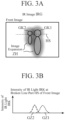
- FIG. 3 illustrates the IR image IRG according to Embodiment 1.
- the low-cost lens causes dispersion of luminance obtained from the IR light IRK to be received, that is, image expansion ZH occurs in the outer shapes GK1 and GK2 of the images GZ1 and GZ2 of the persons JB1 and JB2. Occurrence of the image expansion ZH becomes a factor that deteriorates accuracy of temperatures measured from the persons JB1 and JB2.
- the intensity of the IR light IRK on the broken line part HS in the front image illustrated in FIG. 3A by contrast with the intensity of the visible light KK illustrated in FIG. 2B , as illustrated in FIG. 3B , the intensity of the IR light IRK to be received has a shape of a collapsed rectangle and an extended skirt, in other words, the images GZ1 and GZ2 of the persons JB1 and JB2 are blurred.
- the intensity of the IR light IRK is determined according to what the temperatures of the persons JB1 and JB2 that are measurement targets are, and therefore the peak of the intensity of the IR light IRK reflected by each of the persons JB1 and JB2 is substantially the same.
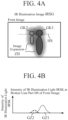
- FIG. 4 illustrates the IR illumination image IRSG according to Embodiment 1.
- the low-cost lens causes occurrence of the image expansion ZH in the IR illumination image IRSG, too.
- the intensity of the IR illumination light IRSK varies according to distances L1 and L2 (illustrated in FIG. 1 ) to the persons JB1 and JB2 in the IR illumination image IRSG.
- An intensity Pr of the IR illumination light IRSK is given by following equation (1). Pr ⁇ P 0 ⁇ exp ⁇ 2 ⁇ L ⁇ R / L 2
- P0 represents power of IR illumination light radiated by the IR illuminating unit 2
- ⁇ represents an attenuation coefficient
- R represents reflectivities of the persons JB1 and JB2
- L represents distances (corresponding to above L1 and L2) to the persons JB1 and JB2.
- the power P0 of the IR illumination light IRSK radiated by the IR illuminating unit 2 is set to such a magnitude that the IR illumination light IRSK can reach the IR image acquiring unit 1 after being reflected by the persons JB1 and JB2 taking an attenuation amount during propagation of the IR illumination light IRSK into account.
- the IR image acquiring unit 1 may receive the IR light IRK and the IR illumination light IRSK without using the wavelength selection device, acquire the IR illumination image IRSG, then calculate a difference between the IR illumination image IRSG and the IR image IRG, and thereby eliminate an influence of the IR light IRK later.
- the processing unit 4 calculates an image expansion amount ZHR (illustrated in FIG. 8 ) of the persons JB1 and JB2.
- the processing unit 4 adds the image expansion amount ZHR to the images GZ1 and GZ2 of the persons JB1 and JB2 in the IR image IRG (illustrated in FIG. 3 ).
- the measuring unit 5 measures the temperatures of the persons JB1 and JB2 based on the images GZ1 and GZ2 of the persons JB1 and JB2 to which the image expansion amount ZHR has been added in the IR image IRG (illustrated in FIG. 3 ).
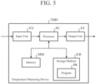
- FIG. 5 illustrates a configuration of the temperature measuring device TMD according to Embodiment 1.
- the temperature measuring device TMD according to Embodiment 1 includes an input unit NY, a processor PC, an output unit SY, a memory MM, and a storage medium KB as illustrated in FIG. 5 to achieve the above-described function. To be more precise, the temperature measuring device TMD according to Embodiment 1 includes the input unit NY and the output unit SY if necessary.
- the input unit NY includes, for example, a camera, a microphone, a keyboard, a mouse, and a touch panel.
- the processor PC is a well-known core of a computer that causes hardware to operate according to software.
- the output unit SY includes, for example, a liquid crystal monitor, a printer, and a touch panel.
- the memory MM includes, for example, a Dynamic Random Access Memory (DRAM) and a Static Random Access Memory (SRAM).
- the storage medium KB includes, for example, a Hard Disk Drive (HDD), a Solid State Drive (SSD), and a Read Only Memory (ROM).
- the storage medium KB stores a program PR.
- the program PR is an instruction set that defines contents of processing that the processor PC needs to execute.
- the processor PC executes the program PR stored in the storage medium KB on the memory MM of the hardware, control operations of the input unit NY and the output unit SY as needed, and thereby implements the function of each unit from the IR image acquiring unit 1 to the measuring unit 5.
- FIG. 6 is a flowchart illustrating an operation of the temperature measuring device TMD according to Embodiment 1. The operation of the temperature measuring device TMD according to Embodiment 1 will be described with reference to the flowchart in FIG. 6 below.
- Step ST11 The IR image acquiring unit 1 (illustrated in FIG. 1 ) acquires the IR image IRG (illustrated in FIG. 3 ) of the persons JB1 and JB2 (illustrated in FIG. 1 ), and acquires the IR illumination image IRSG (illustrated in FIG. 4 ) of the persons JB1 and JB2 under of radiation of the IR illumination light IRSK from the IR illuminating unit 2 (illustrated in FIG. 1 ).
- the visible light image acquiring unit 3 (illustrated in FIG. 1 ) acquires the visible light image KG (illustrated in FIG. 2 ) of the persons JB1 and JB2.
- Step ST12 As illustrated in FIG. 4B , the processing unit 4 (illustrated in FIG. 1 ) calculates the distances L1 and L2 (illustrated in FIG. 1 ) to the persons JB1 and JB2 from the IR illumination image IRSG using the equation (1).
- Step ST13 As illustrated in FIG. 2B , the processing unit 4 derives the outer shapes GK1 and GK2 of the persons JB1 and JB2 from the visible light image KG.
- FIG. 7 illustrates a range ZHH of the image expansion ZH according to Embodiment 1.
- FIG. 8 illustrates the range ZHH and the amount ZHR of the image expansion ZH according to Embodiment 1.
- Step ST14 The processing unit 4 compares the IR illumination image IRSG (illustrated in FIG. 4A ) with the visible light image KG (illustrated in FIG. 2A ), and thereby calculates the range of the image expansion ZH (hereinafter, referred to as the "image expansion range ZHH") in the IR illumination image IRSG as illustrated in FIG. 7 .
- the image expansion range ZHH is a range of the images GZ1 and GZ2 of the persons JB1 and JB2 that expand toward an outer side of the outer shapes GK1 and GK2 of the persons JB1 and JB2.
- Step ST15 As illustrated in FIGS. 8A and 8B , the processing unit 4 integrates luminances of the image expansion range ZHH, and thereby calculates the amount of the image expansion ZH (hereinafter, referred to as the "image expansion amount ZHR").
- the image expansion ZH (illustrated in FIG. 4A ) in the IR illumination image IRSG is equivalent to the image expansion ZH (illustrated in FIG. 3A ) in the IR image IRG. Consequently, the image expansion range ZHH and the image expansion amount ZHR obtained on the IR illumination image IRSG are applicable as is to the IR image IRG.
- Step ST16 The processing unit 4 adds the luminance of the image expansion amount ZHR to luminances of the images GZ1 and GZ2 of the persons JB1 and JB2 on the IR image IRG, and thereby corrects the luminances of the images GZ1 and GZ2 of the persons JB1 and JB2.
- Step ST17 The measuring unit 5 estimates the temperatures of the persons JB1 and JB2 based on the corrected luminances of the images GZ1 and GZ2 of the persons JB1 and JB2, that is, measures the temperatures of the persons JB1 and JB2.
- the temperature measuring device TMD acquires the outer shapes GK1 and GK2 of the images GZ1 and GZ2 of the persons JB1 and JB2 from the visible light image KG, calculates the image expansion amount ZHR by comparing the IR illumination image IRSG with the visible light image KG, adds the image expansion amount ZHR to the images GZ1 and GZ2 of the persons JB1 and JB2 on the IR image IRG, and thereby corrects the luminances of the images GZ1 and GZ2 of the persons JB1 and JB2 on the IR image IRG.
- the temperatures of the persons JB1 and JB2 are measured based on the corrected luminances of the images GZ1 and GZ2 of the persons JB1 and JB2, that is, by taking the image expansion amount ZHR into account, so that it is possible to more accurately measure the temperatures of the persons JB1 and JB2 than the conventional technique that does not take the image expansion ZH into account at all.
- the temperature measuring device TMD according to Embodiment 1 acquires the distances L1 and L2 to the persons JB1 to JB2. Consequently, in addition to the above effect, the temperature measuring device TMD according to Embodiment 1 can separate the images GZ1 and GZ2 of the persons JB1 and JB2 from each other using the above outer shapes GK1 and GK2 of the images GZ1 and GZ2 of the persons JB1 and JB2 and distances L1 and L2 to the persons JB1 and JB2.
- a temperature measuring device according to Embodiment 2 will be described.
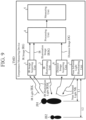
- FIG. 9 is a functional block diagram of a temperature measuring device TMD according to Embodiment 2.
- the temperature measuring device TMD according to Embodiment 2 includes an IR image acquiring unit 1, an IR illuminating unit 2, a processing unit 4, and a measuring unit 5.
- the temperature measuring device TMD according to Embodiment 2 includes a distance image acquiring unit 6 and a near infrared light illuminating unit 7 instead of the visible light image acquiring unit 3.
- IR image acquiring unit 1 Functions of the IR image acquiring unit 1, the IR illuminating unit 2, the processing unit 4, and the measuring unit 5 according to Embodiment 2 are the same as the functions of the IR image acquiring unit 1, the IR illuminating unit 2, the processing unit 4, and the measuring unit 5 according to Embodiment 1.
- the distance image acquiring unit 6 receives near infrared light NK, and thereby acquires an image (hereinafter, referred to as a "distance image DG") showing distances L1 and L2 to persons JB1 and JB2.
- the near infrared light illuminating unit 7 irradiates targets to measure such as the persons JB1 and JB2 with the near infrared light NK (whose wavelength range is 1 to 2 ⁇ m) to enable the distance image acquiring unit 6 to acquire the distance image DG.
- the distance image acquiring unit 6 and the near infrared light illuminating unit 7 adopt, for example, Light Detection and Ranging (LiDAR).
- the distance image acquiring unit 6 and the near infrared light illuminating unit 7 may use, for example, visible light or ultraviolet light instead of the above near infrared light NK.
- the distance image acquiring unit 6 corresponds to a “distance image acquiring unit”
- the near infrared light illuminating unit 7 corresponds to a “distance measurement illuminating unit”
- the near infrared light NK corresponds to "distance measurement illumination light”.
- the processing unit 4 corresponds to a "first acquiring unit” and a “second acquiring unit” in addition to the correspondence in Embodiment 1.
- FIG. 10 illustrates the distance image DG according to Embodiment 2.
- a front image of the distance image DG shows outer shapes GK1 and GK2 of images GZ1 and GZ2 of the persons JB1 and JB2.
- distances L1 and L2 to the persons JB1 and JB2 are obtained according to the intensity of the near infrared light NK in the distance image DG.
- a configuration of the temperature measuring device TMD according to Embodiment 2 is the same as the configuration (illustrated in FIG. 5 ) of the temperature measuring device TMD according to Embodiment 1.
- FIG. 11 is a flowchart illustrating an operation of the temperature measuring device TMD according to Embodiment 2. The operation of the temperature measuring device TMD according to Embodiment 2 will be described with reference to the flowchart in FIG. 11 below.
- Step ST21 Similar to step ST11 in Embodiment 1, the IR image acquiring unit 1 acquires the IR image IRG (illustrated in FIG. 3 ) of the persons JB1 and JB2, and acquires the IR illumination image IRSG (illustrated in FIG. 4 ) of the persons JB1 and JB2 under radiation of IR illumination light IRSK from the IR illuminating unit 2.
- the distance image acquiring unit 6 acquires the distance image DG (illustrated in FIG. 10 ) of the persons JB1 and JB2.
- Step ST22 Unlike step ST12 in Embodiment 1, as illustrated in FIG. 10B , the processing unit 4 acquires the distances L1 and L2 to the persons JB1 and JB2 from the distance image DG using the equation (1).
- Step ST23 Unlike step ST13 in Embodiment 1, as illustrated in FIG. 10A , the processing unit 4 derives the outer shapes GK1 and GK2 of the images GZ1 and GZ2 of the persons JB 1 and JB2 from the distance image DG.
- Step ST24 Unlike step ST14 in Embodiment 1, the processing unit 4 compares the IR illumination image IRSG (illustrated in FIG. 4A ) with the distance image DG (illustrated in FIG. 10A ), and thereby calculates an image expansion range ZHH.
- Step ST25 Similar to step ST15 in Embodiment 1, the processing unit 4 calculates the image expansion amount ZHR.
- Step ST26 Similar to step ST16 in Embodiment 1, the processing unit 4 corrects luminances of the images GZ1 and GZ2 of the persons JB1 and JB2.
- Step ST27 Since power P0 of the IR illumination light IRSK, the distances L1 and L2, and an intensity Pr of the IR illumination image IRSG are known, the processing unit 4 calculates, that is, acquires reflectivities R1 and R2 of the persons JB1 and JB2, respectively, according to the above equation (1).
- calculating the above reflectivities R1 and R2 of the persons JB1 and JB1 is the same as deriving emissivities ⁇ 1 and ⁇ 2 of the persons JB1 and JB2.
- the size of the IR light IRK received by the IR image acquiring unit 1 is proportional to the emissivities ⁇ 1 and ⁇ 2.
- Step ST28 The measuring unit 5 estimates the temperatures of the persons JB1 and JB2 based on the corrected luminances of the images GZ1 and GZ2 of the persons JB1 and JB2 similar to step ST17 in Embodiment 1 by taking the emissivities ⁇ 1 and ⁇ 2 of the persons JB1 and JB2 into account unlike step ST17 in Embodiment 1, that is, measures the temperatures of the persons JB1 and JB2.
- the distance image acquiring unit 6 acquires the distance image DG, and thereby acquires the reflectivities R1 and R2 of the persons JB1 and JB2, in other words, acquires the emissivities ⁇ 1 and ⁇ 2 of the persons JB1 and JB2.
- the temperatures of the persons JB1 and JB2 are measured by taking the emissivities ⁇ 1 and ⁇ 2 into account in addition to an image expansion amount ZHR.
- a temperature measuring device according to Embodiment 3 will be described.
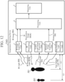
- FIG. 12 is a functional block diagram of a temperature measuring device TMD according to Embodiment 3.
- the temperature measuring device TMD according to Embodiment 3 is a combination of the temperature measuring device TMD (illustrated in FIG. 1 ) according to Embodiment 1 and the temperature measuring device TMD (illustrated in FIG. 9 ) according to Embodiment 2. More specifically, the temperature measuring device TMD according to Embodiment 3 includes an IR image acquiring unit 1, an IR illuminating unit 2, a processing unit 4, and a measuring unit 5 similar to the temperature measuring device TMD according to Embodiment 1 and the temperature measuring device TMD according to Embodiment 2.
- the temperature measuring device TMD according to Embodiment 3 includes a visible light image acquiring unit 3 similar to the temperature measuring device TMD according to Embodiment 1, and includes a distance image acquiring unit 6 and a near infrared light illuminating unit 7 similar to the temperature measuring device TMD according to Embodiment 2.
- the functions of the IR image acquiring unit 1, the IR illuminating unit 2, the visible light image acquiring unit 3, the processing unit 4, the measuring unit 5, the distance image acquiring unit 6, and the near infrared light illuminating unit 7 according to Embodiment 3 are the same as the functions of the IR image acquiring unit 1, the IR illuminating unit 2, the visible light image acquiring unit 3, the processing unit 4, the measuring unit 5, the distance image acquiring unit 6, and the near infrared light illuminating unit 7 according to Embodiments 1 and 2.
- the configuration of the temperature measuring device TMD according to Embodiment 3 is the same as the configuration (illustrated in FIG. 5 ) of the temperature measuring device TMD according to Embodiment 1.
- FIG. 13 is a flowchart illustrating an operation of the temperature measuring device TMD according to Embodiment 3. The operation of the temperature measuring device TMD according to Embodiment 3 will be described with reference to the flowchart in FIG. 13 below.
- Steps ST31 to ST36 Similar to steps ST11 to ST16 in Embodiment 1 and steps ST21 to ST26 in Embodiment 2, the processing unit 4 acquires distances L1 and L2 to persons JB 1 and JB2, outer shapes GK1 and GK2, an image expansion range ZHH, and an image expansion amount ZHR, and corrects luminances of images GZ1 and GZ2 of the persons JB1 and JB2.
- Step ST37 Similar to step ST27 in Embodiment 2, the processing unit 4 calculates reflectivities R1 and R2 of the persons JB1 and JB1, that is, calculates emissivities ⁇ 1 and ⁇ 2 of the persons JB1 and JB2.
- Step ST38 Similar to step ST17 in Embodiment 1 and step ST28 in Embodiment 2, the measuring unit 5 measures the temperatures of the persons JB1 and JB2.
- the temperature measuring device TMD according to Embodiment 3 employs the configuration obtained by combining the temperature measuring device TMD according to Embodiment 1 and the temperature measuring device TMD according to Embodiment 2, and consequently can obtain the effect of the temperature measuring device TMD according to Embodiment 1 and the effect of the temperature measuring device TMD according to Embodiment 2.
- the temperature measuring device TMD uses a distance image DG obtained by the distance image acquiring unit 6 and consequently can improve robustness against environment where temperatures are measured in addition to the above effects even under, for example, environment in which a flare, a ghost, and the like appear in a visible camera included in the visible light image acquiring unit 3, and even under dim environment,.
- the temperature measuring device can be used to measure, for example, temperatures of persons.
- IR image acquiring unit 2: IR illuminating unit, 3: visible light image acquiring unit, 4: processing unit, 5: measuring unit, 6: distance image acquiring unit, 7: near infrared light illuminating unit, DG: distance image, GK1: outer shape, GK2: outer shape, GZ1: image, GZ2: image, HS: broken line portion, IRG: IR image, IRG: IR image, IRK: IR light, IRSG: IR illumination image, IRSK: IR illumination light, JB1: person, JB2: person, KB: storage medium, KG: visible light image, KK: visible light, L1: distance, L2: distance, MM: memory, NK: near infrared light, NY: input unit, P0: power, PC: processor, Pr: intensity, PR: program, R: reflectivity, R1: reflectivity, R2: reflectivity, SY: output unit, TMD: temperature measuring device, ZH: image expansion, ZHH: image
Landscapes
- Physics & Mathematics (AREA)
- General Physics & Mathematics (AREA)
- Spectroscopy & Molecular Physics (AREA)
- Health & Medical Sciences (AREA)
- Toxicology (AREA)
- Engineering & Computer Science (AREA)
- Multimedia (AREA)
- Signal Processing (AREA)
- Radiation Pyrometers (AREA)
Abstract
Description
- The present disclosure relates to a temperature measuring device and a temperature measuring method.
- A thermal image correcting device that is an example of a temperature measuring device and is described in
Patent Literature 1 acquires a temperature distribution of an observation target from a thermal image of the observation target captured by a camera. - Patent Literature 1:
JP 2020-153737 A - According to the above thermal image correcting device, using for the above camera a low-cost lens such as a lens whose cost of a material or number of lenses is reduced expands the above thermal image. As a result, there has been a problem that the accuracy of the temperature distribution of the observation target to be acquired deteriorates.
- An object of the present disclosure is to provide a temperature measuring device and a temperature measuring method that improve accuracy of temperatures of measurement targets.
- To solve the above problem, a temperature measuring device according to the present disclosure includes: a thermal infrared illuminating unit to irradiate with thermal infrared light a target whose temperature needs to be measured; a thermal infrared illumination image acquiring unit to acquire a thermal infrared illumination image including an image of the target irradiated with the thermal infrared light; a thermal infrared image acquiring unit to acquire a thermal infrared image including the image of the target; a visible light image acquiring unit to acquire a visible light image including the image of the target; a calculating unit to calculate an image expansion amount of the image of the target based on the image of the target in the acquired visible light image and the image of the target in the acquired IR illumination image; an adding unit to add the calculated image expansion amount in the acquired thermal infrared image to luminance of the image of the target; and a measuring unit to measure a temperature of the target based on the image of the target to which the image expansion amount has been added.
- The temperature measuring device according to the present disclosure can improve accuracy of temperatures of measurement targets.
-
-
FIG. 1 is a functional block diagram of a temperature measuring device TMD according toEmbodiment 1. -
FIG. 2A illustrates a visible light image KG (part 1) according toEmbodiment 1. -
FIG. 2B illustrates the visible light image KG (part 2) according toEmbodiment 1. -
FIG. 3A illustrates an IR image IRG (part 1) according toEmbodiment 1. -
FIG. 3B illustrates the IR image IRG (part 2) according toEmbodiment 1. -
FIG. 4A illustrates an IR illumination image IRSG (part 1) according toEmbodiment 1. -
FIG. 4B illustrates an IR illumination image IRSG (part 2) according toEmbodiment 1. -
FIG. 5 illustrates a configuration of the temperature measuring device TMD according toEmbodiment 1. -
FIG. 6 is a flowchart illustrating an operation of the temperature measuring device TMD according toEmbodiment 1. -
FIG. 7 illustrates a range ZHH of image expansion ZH according toEmbodiment 1. -
FIG. 8A illustrates the image expansion range ZHH according toEmbodiment 1. -
FIG. 8B illustrates an image expansion amount ZHR according toEmbodiment 1. -
FIG. 9 is a functional block diagram of the temperature measuring device TMD according to Embodiment 2. -
FIG. 10A illustrates a distance image DG (part 1) according to Embodiment 2. -
FIG. 10B illustrates the distance image DG (part 2) according to Embodiment 2. -
FIG. 11 is a flowchart illustrating an operation of the temperature measuring device TMD according to Embodiment 2. -
FIG. 12 is a functional block diagram of the temperature measuring device TMD according to Embodiment 3. -
FIG. 13 is a flowchart illustrating an operation of the temperature measuring device TMD according to Embodiment 3. - Embodiments of a temperature measuring device according to the present disclosure will be described.
- The temperature measuring device according to
Embodiment 1 will be described. -
FIG. 1 is a functional block diagram of a temperature measuring device TMD according toEmbodiment 1. - As illustrated in
FIG. 1 , the temperature measuring device TMD according toEmbodiment 1 includes an IRimage acquiring unit 1, an IR illuminating unit 2, a visible light image acquiring unit 3, a processing unit 4, and a measuring unit 5. - The IR
image acquiring unit 1 corresponds to a "thermal infrared image acquiring unit" and a "thermal infrared illumination image acquiring unit", the IR illuminating unit 2 corresponds to a "thermal infrared irradiating unit", the visible light image acquiring unit 3 corresponds to a "visible light image acquiring unit", the processing unit 4 corresponds to a "calculating unit" and an "adding unit", and the measuring unit 5 corresponds to a "measuring unit". - In this regard, "IR" means InfraRed.
- The following description assumes the followings for ease of description and understanding.
- (1) There are two persons JB1 and JB2 who need to be measured.
- (2) A position of the person JB1 is closer to the temperature measuring device TMD than a position of the person JB2.
- (3) A low-cost lens is used for the IR
image acquiring unit 1 similarly as described in the background art. - The IR
image acquiring unit 1 acquires an IR image IRG of the persons JB1 and JB2 by receiving IR light IRK. The IRimage acquiring unit 1 includes an IR camera (not illustrated) that has sensitivity that comes to a peak in, for example, a mid-infrared wavelength range (3 to 5 µm) and a far-infrared wavelength range (8 to 15 µm), and a wavelength selection device (e.g., a narrow band bandpass filter whose wavelength is 10 µm). - When acquiring an IR illumination image IRSG, the IR
image acquiring unit 1 selectively receives IR illumination light IRSK using the above wavelength selection device, and thereby eliminates light other than the IR illumination light IRSK such as most of the IR light IRK that is reflected by thepersons JB 1 and JB2 and influenced by temperatures of the persons JB1 and JB2. - The IR illuminating unit 2 radiates the IR illumination light IRSK that is infrared light (e.g., above 10 µm) in a wavelength range for which the IR
image acquiring unit 1 has the sensitivity. The IR illuminating unit 2 includes, for example, a halogen lamp, a mid-infrared fiber laser, and a quantum cascade laser. - The IR illuminating unit 2 irradiates the persons JB1 and JB2 with the IR illumination light IRSK, and the IR
image acquiring unit 1 acquires the IR illumination image IRSG of the persons JB1 and JB2 by receiving the IR illumination light IRSK reflected by the persons JB1 and JB2. - The visible light image acquiring unit 3 acquires a visible light image KG of the persons JB1 and JB2. The visible light image acquiring unit 3 includes, for example, a visible camera that has sensitivity whose peak comes in a visible light range.
-
FIG. 2 illustrates the visible light image KG according toEmbodiment 1. - In a front image of the visible light image KG, the person JB1 is captured larger than the person JB2 as illustrated in
FIG. 2A . - As for the intensity of visible light KK on a broken line part HS in the front image illustrated in
FIG. 2A , the intensity of the visible light KK to be received has a rectangular shape as illustrated inFIG. 2B , that is, there is only the visible light KK from the persons JB1 and JB2, i.e., there are only images GZ1 and GZ2 of the persons JB1 and JB2. Consequently, by scanning the intensity of the visible light KK at a plurality of the broken line parts HS (not illustrated) in the front image illustrated inFIG. 2A , it is possible to obtain outer shapes GK1 and GK2 of the persons JB1 and JB2. -
FIG. 3 illustrates the IR image IRG according toEmbodiment 1. - By contrast with the front image of the visible light image KG illustrated in
FIG. 2A , as illustrated inFIG. 3A , in a front image of the IR image IRG, the low-cost lens causes dispersion of luminance obtained from the IR light IRK to be received, that is, image expansion ZH occurs in the outer shapes GK1 and GK2 of the images GZ1 and GZ2 of the persons JB1 and JB2. Occurrence of the image expansion ZH becomes a factor that deteriorates accuracy of temperatures measured from the persons JB1 and JB2. - As for the intensity of the IR light IRK on the broken line part HS in the front image illustrated in
FIG. 3A , by contrast with the intensity of the visible light KK illustrated inFIG. 2B , as illustrated inFIG. 3B , the intensity of the IR light IRK to be received has a shape of a collapsed rectangle and an extended skirt, in other words, the images GZ1 and GZ2 of the persons JB1 and JB2 are blurred. On the other hand, the intensity of the IR light IRK is determined according to what the temperatures of the persons JB1 and JB2 that are measurement targets are, and therefore the peak of the intensity of the IR light IRK reflected by each of the persons JB1 and JB2 is substantially the same. -
FIG. 4 illustrates the IR illumination image IRSG according toEmbodiment 1. - Similar to the IR image IRG illustrated in
FIGS. 3A and 3B , as illustrated inFIGS. 4A and 4B , the low-cost lens causes occurrence of the image expansion ZH in the IR illumination image IRSG, too. - On the other hand, unlike the visible light image KG illustrated in
FIG. 2A and the IR image IRG illustrated inFIG. 3A , the intensity of the IR illumination light IRSK varies according to distances L1 and L2 (illustrated inFIG. 1 ) to the persons JB1 and JB2 in the IR illumination image IRSG. An intensity Pr of the IR illumination light IRSK is given by following equation (1).

- In this regard, P0 represents power of IR illumination light radiated by the IR illuminating unit 2, α represents an attenuation coefficient, R represents reflectivities of the persons JB1 and JB2, and L represents distances (corresponding to above L1 and L2) to the persons JB1 and JB2.
- P0 and α are known, and the reflectivities R of the persons JB1 and JB2 are mutually the same. Consequently, it is possible to obtain the distances L1 and L2 to the persons JB1 and JB2 according to the above equation (1).
- The power P0 of the IR illumination light IRSK radiated by the IR illuminating unit 2 is set to such a magnitude that the IR illumination light IRSK can reach the IR
image acquiring unit 1 after being reflected by the persons JB1 and JB2 taking an attenuation amount during propagation of the IR illumination light IRSK into account. - Instead of eliminating the IR light IRK using the wavelength selection device, then receiving the IR illumination light IRSK, and acquiring the IR illumination image IRSG in advance as described above, for example, the IR
image acquiring unit 1 may receive the IR light IRK and the IR illumination light IRSK without using the wavelength selection device, acquire the IR illumination image IRSG, then calculate a difference between the IR illumination image IRSG and the IR image IRG, and thereby eliminate an influence of the IR light IRK later. - Back to
FIG. 1 , by comparing the outer shapes GK1 and GK2 (illustrated inFIG. 2 ) of the images GZ1 and GZ2 of the persons JB1 and JB2 in the visible light image KG with the outer shapes GK1 and GK2 (illustrated inFIG. 4 ) of the images GZ1 and GZ2 of the persons JB1 and JB2 in the IR illumination image IRSG, the processing unit 4 calculates an image expansion amount ZHR (illustrated inFIG. 8 ) of the persons JB1 and JB2. - The processing unit 4 adds the image expansion amount ZHR to the images GZ1 and GZ2 of the persons JB1 and JB2 in the IR image IRG (illustrated in
FIG. 3 ). - The measuring unit 5 measures the temperatures of the persons JB1 and JB2 based on the images GZ1 and GZ2 of the persons JB1 and JB2 to which the image expansion amount ZHR has been added in the IR image IRG (illustrated in
FIG. 3 ). -
FIG. 5 illustrates a configuration of the temperature measuring device TMD according toEmbodiment 1. - The temperature measuring device TMD according to
Embodiment 1 includes an input unit NY, a processor PC, an output unit SY, a memory MM, and a storage medium KB as illustrated inFIG. 5 to achieve the above-described function. To be more precise, the temperature measuring device TMD according toEmbodiment 1 includes the input unit NY and the output unit SY if necessary. - The input unit NY includes, for example, a camera, a microphone, a keyboard, a mouse, and a touch panel. The processor PC is a well-known core of a computer that causes hardware to operate according to software. The output unit SY includes, for example, a liquid crystal monitor, a printer, and a touch panel. The memory MM includes, for example, a Dynamic Random Access Memory (DRAM) and a Static Random Access Memory (SRAM). The storage medium KB includes, for example, a Hard Disk Drive (HDD), a Solid State Drive (SSD), and a Read Only Memory (ROM).
- The storage medium KB stores a program PR. The program PR is an instruction set that defines contents of processing that the processor PC needs to execute.
- As for a relationship between the function and the configuration of the temperature measuring device TMD, the processor PC executes the program PR stored in the storage medium KB on the memory MM of the hardware, control operations of the input unit NY and the output unit SY as needed, and thereby implements the function of each unit from the IR
image acquiring unit 1 to the measuring unit 5. -
FIG. 6 is a flowchart illustrating an operation of the temperature measuring device TMD according toEmbodiment 1. The operation of the temperature measuring device TMD according toEmbodiment 1 will be described with reference to the flowchart inFIG. 6 below. - Step ST11: The IR image acquiring unit 1 (illustrated in
FIG. 1 ) acquires the IR image IRG (illustrated inFIG. 3 ) of the persons JB1 and JB2 (illustrated inFIG. 1 ), and acquires the IR illumination image IRSG (illustrated inFIG. 4 ) of the persons JB1 and JB2 under of radiation of the IR illumination light IRSK from the IR illuminating unit 2 (illustrated inFIG. 1 ). The visible light image acquiring unit 3 (illustrated inFIG. 1 ) acquires the visible light image KG (illustrated inFIG. 2 ) of the persons JB1 and JB2. - Step ST12: As illustrated in
FIG. 4B , the processing unit 4 (illustrated inFIG. 1 ) calculates the distances L1 and L2 (illustrated inFIG. 1 ) to the persons JB1 and JB2 from the IR illumination image IRSG using the equation (1). - Step ST13: As illustrated in
FIG. 2B , the processing unit 4 derives the outer shapes GK1 and GK2 of the persons JB1 and JB2 from the visible light image KG. -
FIG. 7 illustrates a range ZHH of the image expansion ZH according toEmbodiment 1. -
FIG. 8 illustrates the range ZHH and the amount ZHR of the image expansion ZH according toEmbodiment 1. - Step ST14: The processing unit 4 compares the IR illumination image IRSG (illustrated in
FIG. 4A ) with the visible light image KG (illustrated inFIG. 2A ), and thereby calculates the range of the image expansion ZH (hereinafter, referred to as the "image expansion range ZHH") in the IR illumination image IRSG as illustrated inFIG. 7 . As illustrated inFIG. 7 , the image expansion range ZHH is a range of the images GZ1 and GZ2 of the persons JB1 and JB2 that expand toward an outer side of the outer shapes GK1 and GK2 of the persons JB1 and JB2. - Step ST15: As illustrated in
FIGS. 8A and 8B , the processing unit 4 integrates luminances of the image expansion range ZHH, and thereby calculates the amount of the image expansion ZH (hereinafter, referred to as the "image expansion amount ZHR"). - The image expansion ZH (illustrated in
FIG. 4A ) in the IR illumination image IRSG is equivalent to the image expansion ZH (illustrated inFIG. 3A ) in the IR image IRG. Consequently, the image expansion range ZHH and the image expansion amount ZHR obtained on the IR illumination image IRSG are applicable as is to the IR image IRG. - Step ST16: The processing unit 4 adds the luminance of the image expansion amount ZHR to luminances of the images GZ1 and GZ2 of the persons JB1 and JB2 on the IR image IRG, and thereby corrects the luminances of the images GZ1 and GZ2 of the persons JB1 and JB2.
- Step ST17: The measuring unit 5 estimates the temperatures of the persons JB1 and JB2 based on the corrected luminances of the images GZ1 and GZ2 of the persons JB1 and JB2, that is, measures the temperatures of the persons JB1 and JB2.
- As described above, the temperature measuring device TMD according to
Embodiment 1 acquires the outer shapes GK1 and GK2 of the images GZ1 and GZ2 of the persons JB1 and JB2 from the visible light image KG, calculates the image expansion amount ZHR by comparing the IR illumination image IRSG with the visible light image KG, adds the image expansion amount ZHR to the images GZ1 and GZ2 of the persons JB1 and JB2 on the IR image IRG, and thereby corrects the luminances of the images GZ1 and GZ2 of the persons JB1 and JB2 on the IR image IRG. The temperatures of the persons JB1 and JB2 are measured based on the corrected luminances of the images GZ1 and GZ2 of the persons JB1 and JB2, that is, by taking the image expansion amount ZHR into account, so that it is possible to more accurately measure the temperatures of the persons JB1 and JB2 than the conventional technique that does not take the image expansion ZH into account at all. - The temperature measuring device TMD according to
Embodiment 1 acquires the distances L1 and L2 to the persons JB1 to JB2. Consequently, in addition to the above effect, the temperature measuring device TMD according toEmbodiment 1 can separate the images GZ1 and GZ2 of the persons JB1 and JB2 from each other using the above outer shapes GK1 and GK2 of the images GZ1 and GZ2 of the persons JB1 and JB2 and distances L1 and L2 to the persons JB1 and JB2. - A temperature measuring device according to Embodiment 2 will be described.
-
FIG. 9 is a functional block diagram of a temperature measuring device TMD according to Embodiment 2. - Similar to the temperature measuring device TMD according to
Embodiment 1, as illustrated inFIG. 9 , the temperature measuring device TMD according to Embodiment 2 includes an IRimage acquiring unit 1, an IR illuminating unit 2, a processing unit 4, and a measuring unit 5. On the other hand, unlike the temperature measuring device TMD according toEmbodiment 1, the temperature measuring device TMD according to Embodiment 2 includes a distance image acquiring unit 6 and a near infraredlight illuminating unit 7 instead of the visible light image acquiring unit 3. - Functions of the IR
image acquiring unit 1, the IR illuminating unit 2, the processing unit 4, and the measuring unit 5 according to Embodiment 2 are the same as the functions of the IRimage acquiring unit 1, the IR illuminating unit 2, the processing unit 4, and the measuring unit 5 according toEmbodiment 1. - The distance image acquiring unit 6 receives near infrared light NK, and thereby acquires an image (hereinafter, referred to as a "distance image DG") showing distances L1 and L2 to persons JB1 and JB2.
- The near infrared
light illuminating unit 7 irradiates targets to measure such as the persons JB1 and JB2 with the near infrared light NK (whose wavelength range is 1 to 2 µm) to enable the distance image acquiring unit 6 to acquire the distance image DG. - The distance image acquiring unit 6 and the near infrared
light illuminating unit 7 adopt, for example, Light Detection and Ranging (LiDAR). The distance image acquiring unit 6 and the near infraredlight illuminating unit 7 may use, for example, visible light or ultraviolet light instead of the above near infrared light NK. - The distance image acquiring unit 6 corresponds to a "distance image acquiring unit", the near infrared
light illuminating unit 7 corresponds to a "distance measurement illuminating unit", and the near infrared light NK corresponds to "distance measurement illumination light". - The processing unit 4 corresponds to a "first acquiring unit" and a "second acquiring unit" in addition to the correspondence in
Embodiment 1. -
FIG. 10 illustrates the distance image DG according to Embodiment 2. - Similar to the visible light image KG (illustrated in 2A), as illustrated in
FIG. 10A , a front image of the distance image DG shows outer shapes GK1 and GK2 of images GZ1 and GZ2 of the persons JB1 and JB2. - Similar to the IR illumination image IRSG (illustrated in
FIG. 4B ), as suggested inFIG. 10B , distances L1 and L2 to the persons JB1 and JB2 are obtained according to the intensity of the near infrared light NK in the distance image DG. - A configuration of the temperature measuring device TMD according to Embodiment 2 is the same as the configuration (illustrated in
FIG. 5 ) of the temperature measuring device TMD according toEmbodiment 1. -
FIG. 11 is a flowchart illustrating an operation of the temperature measuring device TMD according to Embodiment 2. The operation of the temperature measuring device TMD according to Embodiment 2 will be described with reference to the flowchart inFIG. 11 below. - Step ST21: Similar to step ST11 in
Embodiment 1, the IRimage acquiring unit 1 acquires the IR image IRG (illustrated inFIG. 3 ) of the persons JB1 and JB2, and acquires the IR illumination image IRSG (illustrated inFIG. 4 ) of the persons JB1 and JB2 under radiation of IR illumination light IRSK from the IR illuminating unit 2. On the other hand, unlike step ST11 inEmbodiment 1, the distance image acquiring unit 6 acquires the distance image DG (illustrated inFIG. 10 ) of the persons JB1 and JB2. - Step ST22: Unlike step ST12 in
Embodiment 1, as illustrated inFIG. 10B , the processing unit 4 acquires the distances L1 and L2 to the persons JB1 and JB2 from the distance image DG using the equation (1). - Step ST23: Unlike step ST13 in
Embodiment 1, as illustrated inFIG. 10A , the processing unit 4 derives the outer shapes GK1 and GK2 of the images GZ1 and GZ2 of thepersons JB 1 and JB2 from the distance image DG. - Step ST24: Unlike step ST14 in
Embodiment 1, the processing unit 4 compares the IR illumination image IRSG (illustrated inFIG. 4A ) with the distance image DG (illustrated inFIG. 10A ), and thereby calculates an image expansion range ZHH. - Step ST25: Similar to step ST15 in
Embodiment 1, the processing unit 4 calculates the image expansion amount ZHR. - Step ST26: Similar to step ST16 in
Embodiment 1, the processing unit 4 corrects luminances of the images GZ1 and GZ2 of the persons JB1 and JB2. - Step ST27: Since power P0 of the IR illumination light IRSK, the distances L1 and L2, and an intensity Pr of the IR illumination image IRSG are known, the processing unit 4 calculates, that is, acquires reflectivities R1 and R2 of the persons JB1 and JB2, respectively, according to the above equation (1).
- When transmittance is 0, the following equation (2) holds according to the Kirchhoff's Law.

- Hence, calculating the above reflectivities R1 and R2 of the persons JB1 and JB1 is the same as deriving emissivities ε1 and ε2 of the persons JB1 and JB2. The size of the IR light IRK received by the IR
image acquiring unit 1 is proportional to the emissivities ε1 and ε2. - Step ST28: The measuring unit 5 estimates the temperatures of the persons JB1 and JB2 based on the corrected luminances of the images GZ1 and GZ2 of the persons JB1 and JB2 similar to step ST17 in
Embodiment 1 by taking the emissivities ε1 and ε2 of the persons JB1 and JB2 into account unlike step ST17 inEmbodiment 1, that is, measures the temperatures of the persons JB1 and JB2. - As described above, in the temperature measuring device TMD according to Embodiment 2, the distance image acquiring unit 6 acquires the distance image DG, and thereby acquires the reflectivities R1 and R2 of the persons JB1 and JB2, in other words, acquires the emissivities ε1 and ε2 of the persons JB1 and JB2. Thus, unlike
Embodiment 1 where only the image expansion amount ZHR is taken into account, the temperatures of the persons JB1 and JB2 are measured by taking the emissivities ε1 and ε2 into account in addition to an image expansion amount ZHR. As a result, it is possible to more accurately measure the temperatures of the persons JB1 and JB2 than the temperature measuring device TMD according toEmbodiment 1. - A temperature measuring device according to Embodiment 3 will be described.
-
FIG. 12 is a functional block diagram of a temperature measuring device TMD according to Embodiment 3. - As illustrated in
FIG. 12 , the temperature measuring device TMD according to Embodiment 3 is a combination of the temperature measuring device TMD (illustrated inFIG. 1 ) according toEmbodiment 1 and the temperature measuring device TMD (illustrated inFIG. 9 ) according to Embodiment 2. More specifically, the temperature measuring device TMD according to Embodiment 3 includes an IRimage acquiring unit 1, an IR illuminating unit 2, a processing unit 4, and a measuring unit 5 similar to the temperature measuring device TMD according toEmbodiment 1 and the temperature measuring device TMD according to Embodiment 2. The temperature measuring device TMD according to Embodiment 3 includes a visible light image acquiring unit 3 similar to the temperature measuring device TMD according toEmbodiment 1, and includes a distance image acquiring unit 6 and a near infraredlight illuminating unit 7 similar to the temperature measuring device TMD according to Embodiment 2. - The functions of the IR
image acquiring unit 1, the IR illuminating unit 2, the visible light image acquiring unit 3, the processing unit 4, the measuring unit 5, the distance image acquiring unit 6, and the near infraredlight illuminating unit 7 according to Embodiment 3 are the same as the functions of the IRimage acquiring unit 1, the IR illuminating unit 2, the visible light image acquiring unit 3, the processing unit 4, the measuring unit 5, the distance image acquiring unit 6, and the near infraredlight illuminating unit 7 according toEmbodiments 1 and 2. - The configuration of the temperature measuring device TMD according to Embodiment 3 is the same as the configuration (illustrated in
FIG. 5 ) of the temperature measuring device TMD according toEmbodiment 1. -
FIG. 13 is a flowchart illustrating an operation of the temperature measuring device TMD according to Embodiment 3. The operation of the temperature measuring device TMD according to Embodiment 3 will be described with reference to the flowchart inFIG. 13 below. - Steps ST31 to ST36: Similar to steps ST11 to ST16 in
Embodiment 1 and steps ST21 to ST26 in Embodiment 2, the processing unit 4 acquires distances L1 and L2 topersons JB 1 and JB2, outer shapes GK1 and GK2, an image expansion range ZHH, and an image expansion amount ZHR, and corrects luminances of images GZ1 and GZ2 of the persons JB1 and JB2. - Step ST37: Similar to step ST27 in Embodiment 2, the processing unit 4 calculates reflectivities R1 and R2 of the persons JB1 and JB1, that is, calculates emissivities ε1 and ε2 of the persons JB1 and JB2.
- Step ST38: Similar to step ST17 in
Embodiment 1 and step ST28 in Embodiment 2, the measuring unit 5 measures the temperatures of the persons JB1 and JB2. - As described above, the temperature measuring device TMD according to Embodiment 3 employs the configuration obtained by combining the temperature measuring device TMD according to
Embodiment 1 and the temperature measuring device TMD according to Embodiment 2, and consequently can obtain the effect of the temperature measuring device TMD according toEmbodiment 1 and the effect of the temperature measuring device TMD according to Embodiment 2. - The temperature measuring device TMD according to Embodiment 3 uses a distance image DG obtained by the distance image acquiring unit 6 and consequently can improve robustness against environment where temperatures are measured in addition to the above effects even under, for example, environment in which a flare, a ghost, and the like appear in a visible camera included in the visible light image acquiring unit 3, and even under dim environment,.
- The above-described embodiments may be combined without departing from the gist of the present disclosure, and the components in each embodiment may be deleted or changed, or other components may be added as appropriate.
- The temperature measuring device according to the present disclosure can be used to measure, for example, temperatures of persons.
- 1: IR image acquiring unit, 2: IR illuminating unit, 3: visible light image acquiring unit, 4: processing unit, 5: measuring unit, 6: distance image acquiring unit, 7: near infrared light illuminating unit, DG: distance image, GK1: outer shape, GK2: outer shape, GZ1: image, GZ2: image, HS: broken line portion, IRG: IR image, IRG: IR image, IRK: IR light, IRSG: IR illumination image, IRSK: IR illumination light, JB1: person, JB2: person, KB: storage medium, KG: visible light image, KK: visible light, L1: distance, L2: distance, MM: memory, NK: near infrared light, NY: input unit, P0: power, PC: processor, Pr: intensity, PR: program, R: reflectivity, R1: reflectivity, R2: reflectivity, SY: output unit, TMD: temperature measuring device, ZH: image expansion, ZHH: image expansion range, ZHR: image expansion amount, ε1: emissivity, ε2: emissivity
Claims (6)
- A temperature measuring device comprising:a thermal infrared illuminating unit to irradiate with thermal infrared light a target whose temperature needs to be measured;a thermal infrared illumination image acquiring unit to acquire a thermal infrared illumination image including an image of the target irradiated with the thermal infrared light;a thermal infrared image acquiring unit to acquire a thermal infrared image including the image of the target;a visible light image acquiring unit to acquire a visible light image including the image of the target;a calculating unit to calculate an image expansion amount of the image of the target based on the image of the target in the acquired visible light image and the image of the target in the acquired IR illumination image;an adding unit to add the calculated image expansion amount in the acquired thermal infrared image to luminance of the image of the target; anda measuring unit to measure a temperature of the target based on the image of the target to which the image expansion amount has been added.
- A temperature measuring device comprising:a thermal infrared illuminating unit to irradiate with thermal infrared light a target whose temperature needs to be measured;a thermal infrared illumination image acquiring unit to acquire a thermal infrared illumination image including an image of the target irradiated with the thermal infrared light;a thermal infrared image acquiring unit to acquire a thermal infrared image including the image of the target;a distance measurement illuminating unit to irradiate the target with distance measurement illumination light for measuring a distance;a distance image acquiring unit to acquire a distance image including the image of the target irradiated with the distance measurement illumination light;a calculating unit to calculate an image expansion amount of the image of the target based on the image of the target in the acquired distance image and the image of the target in the acquired thermal infrared illumination image;an adding unit to add the calculated image expansion amount in the acquired thermal infrared image to luminance of the image of the target;a first acquiring unit to acquire a distance to the target based on the acquired distance image;a second acquiring unit to acquire emissivity of the target based on the acquired distance; anda measuring unit to measure a temperature of the target based on the image of the target to which the image expansion amount has been added, and the acquired emissivity of the target.
- A temperature measuring device comprising:a thermal infrared illuminating unit to irradiate with thermal infrared light a target whose temperature needs to be measured;a thermal infrared illumination image acquiring unit to acquire a thermal infrared illumination image including an image of the target irradiated with the thermal infrared light;a thermal infrared image acquiring unit to acquire a thermal infrared image including the image of the target;a visible light image acquiring unit to acquire a visible light image including the image of the target;a distance measurement illuminating unit to irradiate the target with distance measurement illumination light for measuring a distance;a distance image acquiring unit to acquire a distance image including the image of the target irradiated with the distance measurement illumination light;a calculating unit to calculate an image expansion amount of the image of the target based on one of the image of the target in the acquired visible light image and the image of the target in the acquired distance image, and the image of the target in the acquired thermal infrared illumination image;an adding unit to add the calculated image expansion amount in the thermal infrared image to luminance of the image of the target;a first acquiring unit to acquire a distance to the target based on the acquired distance image;a second acquiring unit to acquire emissivity of the target based on the acquired distance; anda measuring unit to measure a temperature of the target based on the image of the target to which the image expansion amount has been added, and the calculated emissivity of the target.
- A temperature measuring method comprising:by a thermal infrared illuminating unit, irradiating with thermal infrared light a target whose temperature needs to be measured;by a thermal infrared illumination image acquiring unit, acquiring a thermal infrared illumination image including an image of the target irradiated with the thermal infrared light;by a thermal infrared image acquiring unit, acquiring a thermal infrared image including the image of the target;by a visible light image acquiring unit, acquiring a visible light image including the image of the target;by a calculating unit, calculating an image expansion amount of the image of the target based on the image of the target in the acquired visible light image and the image of the target in the acquired IR illumination image;by an adding unit, adding the calculated image expansion amount in the acquired thermal infrared image to luminance of the image of the target; andby a measuring unit, measuring a temperature of the target based on the image of the target to which the image expansion amount has been added.
- A temperature measuring method comprising:by a thermal infrared illuminating unit, irradiating with thermal infrared light a target whose temperature needs to be measured;by a thermal infrared illumination image acquiring unit, acquiring a thermal infrared illumination image including an image of the target irradiated with the thermal infrared light;by a thermal infrared image acquiring unit, acquiring a thermal infrared image including the image of the target;by a distance measurement illuminating unit, irradiating the target with distance measurement illumination light for measuring a distance;by a distance image acquiring unit, acquiring a distance image including the image of the target irradiated with the distance measurement illumination light;by a calculating unit, calculating an image expansion amount of the image of the target based on the image of the target in the acquired distance image and the image of the target in the acquired thermal infrared illumination image;by an adding unit, adding the calculated image expansion amount in the acquired thermal infrared image to luminance of the image of the target;by a first acquiring unit, acquiring a distance to the target based on the acquired distance image;by a second acquiring unit, acquiring emissivity of the target based on the acquired distance; andby a measuring unit, measuring a temperature of the target based on the image of the target to which the image expansion amount has been added, and the acquired emissivity of the target.
- A temperature measuring method comprising:by a thermal infrared illuminating unit, irradiating with thermal infrared light a target whose temperature needs to be measured;by a thermal infrared illumination image acquiring unit, acquiring a thermal infrared illumination image including an image of the target irradiated with the thermal infrared light;by a thermal infrared image acquiring unit, acquiring a thermal infrared image including the image of the target;by a visible light image acquiring unit, acquiring a visible light image including the image of the target;by a distance measurement illuminating unit, irradiating the target with distance measurement illumination light for measuring a distance;by a distance image acquiring unit, acquiring a distance image including the image of the target irradiated with the distance measurement illumination light;by a calculating unit, calculating an image expansion amount of the image of the target based on one of the image of the target in the acquired visible light image and the image of the target in the acquired distance image, and the image of the target in the acquired thermal infrared illumination image;by an adding unit, adding the calculated image expansion amount in the thermal infrared image to luminance of the image of the target;by a first acquiring unit, acquiring a distance to the target based on the acquired distance image;by a second acquiring unit, acquiring emissivity of the target based on the acquired distance; andby a measuring unit, measure a temperature of the target based on the image of the target to which the image expansion amount has been added, and the calculated emissivity of the target.
Applications Claiming Priority (1)
| Application Number | Priority Date | Filing Date | Title |
|---|---|---|---|
| PCT/JP2021/021110 WO2022254642A1 (en) | 2021-06-03 | 2021-06-03 | Temperature measuring device and temperature measuring method |
Publications (3)
| Publication Number | Publication Date |
|---|---|
| EP4332526A1 true EP4332526A1 (en) | 2024-03-06 |
| EP4332526A4 EP4332526A4 (en) | 2024-06-19 |
| EP4332526B1 EP4332526B1 (en) | 2025-06-25 |
Family
ID=84324014
Family Applications (1)
| Application Number | Title | Priority Date | Filing Date |
|---|---|---|---|
| EP21944144.1A Active EP4332526B1 (en) | 2021-06-03 | 2021-06-03 | Temperature measuring device and temperature measuring method |
Country Status (5)
| Country | Link |
|---|---|
| US (1) | US20230417600A1 (en) |
| EP (1) | EP4332526B1 (en) |
| JP (1) | JP7546775B2 (en) |
| CN (1) | CN117355731A (en) |
| WO (1) | WO2022254642A1 (en) |
Family Cites Families (37)
| Publication number | Priority date | Publication date | Assignee | Title |
|---|---|---|---|---|
| JPH09218100A (en) * | 1996-02-09 | 1997-08-19 | Mitsubishi Heavy Ind Ltd | Indication device of temperature distribution |
| US6107618A (en) * | 1997-07-14 | 2000-08-22 | California Institute Of Technology | Integrated infrared and visible image sensors |
| JP3565549B2 (en) * | 1998-09-24 | 2004-09-15 | 東海カーボン株式会社 | Method and apparatus for measuring weld temperature of welded pipe |
| US7057256B2 (en) * | 2001-05-25 | 2006-06-06 | President & Fellows Of Harvard College | Silicon-based visible and near-infrared optoelectric devices |
| JP2005037366A (en) * | 2003-06-24 | 2005-02-10 | Constec Engi Co | Infrared structure diagnostic system and infrared structure diagnostic method |
| US8045764B2 (en) * | 2005-01-26 | 2011-10-25 | Honeywell International Inc. | Expedient encoding system |
| KR100648308B1 (en) * | 2004-08-12 | 2006-11-23 | 삼성전자주식회사 | Resolution conversion method and device |
| EP1831657B1 (en) * | 2004-12-03 | 2018-12-05 | Fluke Corporation | Method for a visible light and ir combined image camera |
| US7629582B2 (en) * | 2006-10-24 | 2009-12-08 | Raytheon Company | Dual band imager with visible or SWIR detectors combined with uncooled LWIR detectors |
| US7813889B2 (en) * | 2008-01-16 | 2010-10-12 | Welch Allyn, Inc. | Guiding IR temperature measuring device with probe cover |
| CA2718972A1 (en) * | 2008-03-19 | 2009-09-24 | Hypermed, Inc. | Miniaturized multi-spectral imager for real-time tissue oxygenation measurement |
| US20090273675A1 (en) * | 2008-05-05 | 2009-11-05 | Flir Systems Ab | Ir camera and method for use with ir camera |
| US7915652B2 (en) * | 2008-10-24 | 2011-03-29 | Sharp Laboratories Of America, Inc. | Integrated infrared and color CMOS imager sensor |
| US8520970B2 (en) * | 2010-04-23 | 2013-08-27 | Flir Systems Ab | Infrared resolution and contrast enhancement with fusion |
| WO2012095322A1 (en) * | 2011-01-14 | 2012-07-19 | Sony Corporation | Imaging system using a lens unit with longitudinal chromatic aberrations and method of operating |
| EP2530442A1 (en) * | 2011-05-30 | 2012-12-05 | Axis AB | Methods and apparatus for thermographic measurements. |
| JP5861190B2 (en) * | 2012-12-12 | 2016-02-16 | トヨタ自動車株式会社 | Non-contact temperature measurement method and non-contact temperature measurement device |
| US10063788B2 (en) * | 2013-02-08 | 2018-08-28 | Denso Corporation | Night-vision image processing apparatus |
| US20140267757A1 (en) * | 2013-03-15 | 2014-09-18 | Fluke Corporation | Parallax correction in thermal imaging cameras |
| JP6247425B2 (en) * | 2015-04-23 | 2017-12-13 | 富士フイルム株式会社 | Image processing apparatus, imaging apparatus, image processing method, and image processing program |
| CN107836111B (en) * | 2015-06-05 | 2020-08-11 | 菲力尔系统公司 | System and method for enhanced dynamic range infrared imaging |
| US10152811B2 (en) * | 2015-08-27 | 2018-12-11 | Fluke Corporation | Edge enhancement for thermal-visible combined images and cameras |
| JP6711396B2 (en) * | 2016-03-29 | 2020-06-17 | ソニー株式会社 | Image processing device, imaging device, image processing method, and program |
| JP6620827B2 (en) * | 2017-04-14 | 2019-12-18 | Jfeスチール株式会社 | Radiation temperature measuring device and radiation temperature measuring method |
| GB2577646B (en) * | 2017-06-03 | 2022-09-14 | Teledyne FLIR LLC | Extensible architecture for surveillance and targeting imaging systems and methods |
| JP6939283B2 (en) * | 2017-09-05 | 2021-09-22 | ソニーグループ株式会社 | Image processing device, image processing method, and program |
| US10684370B2 (en) * | 2017-09-29 | 2020-06-16 | Veoneer Us, Inc. | Multifunction vehicle detection system |
| US20190141236A1 (en) * | 2017-11-06 | 2019-05-09 | Fluke Corporation | Inspection workflow using ojbect recognition and other techniques |
| US10850693B1 (en) * | 2018-04-05 | 2020-12-01 | Ambarella International Lp | Determining comfort settings in vehicles using computer vision |
| JP7129271B2 (en) * | 2018-08-16 | 2022-09-01 | セコム株式会社 | Image processing device |
| US11186241B2 (en) * | 2019-01-30 | 2021-11-30 | Cobalt Industries Inc. | Automated emotion detection and environmental response |
| JP2020139866A (en) * | 2019-02-28 | 2020-09-03 | 三星電子株式会社Samsung Electronics Co.,Ltd. | Temperature measuring device, cooking device, and temperature measuring method |
| JP7259438B2 (en) | 2019-03-19 | 2023-04-18 | コニカミノルタ株式会社 | THERMAL IMAGE CORRECTION DEVICE, THERMAL IMAGE CORRECTION METHOD, AND THERMAL IMAGE CORRECTION PROGRAM |
| US11336741B2 (en) * | 2019-11-01 | 2022-05-17 | Microsoft Technology Licensing, Llc | Image data segmentation and transmission |
| JP7404806B2 (en) * | 2019-11-22 | 2023-12-26 | 株式会社リコー | Imaging system, imaging optical system, and image processing method |
| US11816905B2 (en) * | 2020-03-19 | 2023-11-14 | Magna Electronics Inc. | Multi-camera vision system integrated into interior rearview mirror |
| CN111537083A (en) * | 2020-06-22 | 2020-08-14 | 益逻触控系统公司 | Method and apparatus for measuring body temperature of a person |
-
2021
- 2021-06-03 CN CN202180098640.9A patent/CN117355731A/en active Pending
- 2021-06-03 EP EP21944144.1A patent/EP4332526B1/en active Active
- 2021-06-03 JP JP2023525269A patent/JP7546775B2/en active Active
- 2021-06-03 WO PCT/JP2021/021110 patent/WO2022254642A1/en not_active Ceased
-
2023
- 2023-09-13 US US18/367,554 patent/US20230417600A1/en active Pending
Also Published As
| Publication number | Publication date |
|---|---|
| US20230417600A1 (en) | 2023-12-28 |
| JPWO2022254642A1 (en) | 2022-12-08 |
| WO2022254642A1 (en) | 2022-12-08 |
| CN117355731A (en) | 2024-01-05 |
| EP4332526A4 (en) | 2024-06-19 |
| JP7546775B2 (en) | 2024-09-06 |
| EP4332526B1 (en) | 2025-06-25 |
Similar Documents
| Publication | Publication Date | Title |
|---|---|---|
| Lough et al. | Correlation of SWIR imaging with LPBF 304L stainless steel part properties | |
| EP3392635B1 (en) | Image processing device for gas detection, image processing method for gas detection, image processing program for gas detection, computer-readable recording medium having image processing program for gas detection recorded thereon, and gas detection system | |
| RU2557674C2 (en) | Generation of spatial topographic images of tool traces with help of nonlinear photometric stereo process | |
| US7457721B2 (en) | Method and apparatus for measuring small displacement | |
| WO2009146906A3 (en) | Ophthalmological laser system and operating method | |
| EP4043865A1 (en) | Photography device | |
| KR20210024468A (en) | Film thickness measurement device and correction method | |
| JP2021179404A (en) | Temperature measurement system | |
| KR102049242B1 (en) | Image processing apparatus, image processing method, and optical coherence tomography apparatus | |
| EP3211456A1 (en) | Data processing device, method for determining characteristics of pixels, data processing method, and program | |
| US8917393B2 (en) | Method and apparatus for providing image data | |
| EP4332526A1 (en) | Temperature measuring device and temperature measuring method | |
| US20060136172A1 (en) | Method for modeling detection of camouflaged targets | |
| Wolfgang et al. | Real-time monitoring of multiparticulate coating processes at industrial-scale using ultra-high-resolution optical coherence tomography | |
| Escudero et al. | Robust automatic retrieval of soot volume fraction, temperature and radiation for axisymmetric flames | |
| US20170172405A1 (en) | Ophthalmologic information processing apparatus and ophthalmologic information processing method | |
| US20070140429A1 (en) | Method for monitoring an x-ray apparatus and x-ray apparatus | |
| EP3583893B1 (en) | Scattered body measurement device and scattered body measurement method | |
| Zheng et al. | 3D flame surface curvature analysis from reconstructed scanning across spherical expanding flames | |
| Bendo et al. | Polycyclic aromatic hydrocarbon excitation in nearby spiral galaxies | |
| JPH0663848B2 (en) | How to measure the surface temperature of an object | |
| EP2113767A1 (en) | Computed tomography systems and related methods involving localized bias | |
| KR20210155223A (en) | Thermal image camera | |
| Jakkula et al. | Direct measurement of necking strain using optical contour analysis on isotropic ductile stainless steel | |
| Kajita et al. | Influence of stray light for divertor spectroscopy in ITER |
Legal Events
| Date | Code | Title | Description |
|---|---|---|---|
| STAA | Information on the status of an ep patent application or granted ep patent |
Free format text: STATUS: THE INTERNATIONAL PUBLICATION HAS BEEN MADE |
|
| PUAI | Public reference made under article 153(3) epc to a published international application that has entered the european phase |
Free format text: ORIGINAL CODE: 0009012 |
|
| STAA | Information on the status of an ep patent application or granted ep patent |
Free format text: STATUS: REQUEST FOR EXAMINATION WAS MADE |
|
| 17P | Request for examination filed |
Effective date: 20231124 |
|
| AK | Designated contracting states |
Kind code of ref document: A1 Designated state(s): AL AT BE BG CH CY CZ DE DK EE ES FI FR GB GR HR HU IE IS IT LI LT LU LV MC MK MT NL NO PL PT RO RS SE SI SK SM TR |
|
| A4 | Supplementary search report drawn up and despatched |
Effective date: 20240522 |
|
| RIC1 | Information provided on ipc code assigned before grant |
Ipc: G01J 5/48 20220101AFI20240515BHEP |
|
| DAV | Request for validation of the european patent (deleted) | ||
| DAX | Request for extension of the european patent (deleted) | ||
| GRAP | Despatch of communication of intention to grant a patent |
Free format text: ORIGINAL CODE: EPIDOSNIGR1 |
|
| STAA | Information on the status of an ep patent application or granted ep patent |
Free format text: STATUS: GRANT OF PATENT IS INTENDED |
|
| INTG | Intention to grant announced |
Effective date: 20250212 |
|
| GRAS | Grant fee paid |
Free format text: ORIGINAL CODE: EPIDOSNIGR3 |
|
| GRAA | (expected) grant |
Free format text: ORIGINAL CODE: 0009210 |
|
| STAA | Information on the status of an ep patent application or granted ep patent |
Free format text: STATUS: THE PATENT HAS BEEN GRANTED |
|
| AK | Designated contracting states |
Kind code of ref document: B1 Designated state(s): AL AT BE BG CH CY CZ DE DK EE ES FI FR GB GR HR HU IE IS IT LI LT LU LV MC MK MT NL NO PL PT RO RS SE SI SK SM TR |
|
| REG | Reference to a national code |
Ref country code: GB Ref legal event code: FG4D |
|
| REG | Reference to a national code |
Ref country code: CH Ref legal event code: EP |
|
| REG | Reference to a national code |
Ref country code: CH Ref legal event code: EP |
|
| REG | Reference to a national code |
Ref country code: IE Ref legal event code: FG4D |
|
| REG | Reference to a national code |
Ref country code: DE Ref legal event code: R096 Ref document number: 602021033121 Country of ref document: DE |
|
| PG25 | Lapsed in a contracting state [announced via postgrant information from national office to epo] |
Ref country code: FI Free format text: LAPSE BECAUSE OF FAILURE TO SUBMIT A TRANSLATION OF THE DESCRIPTION OR TO PAY THE FEE WITHIN THE PRESCRIBED TIME-LIMIT Effective date: 20250625 |
|
| REG | Reference to a national code |
Ref country code: LT Ref legal event code: MG9D |
|
| PG25 | Lapsed in a contracting state [announced via postgrant information from national office to epo] |
Ref country code: NO Free format text: LAPSE BECAUSE OF FAILURE TO SUBMIT A TRANSLATION OF THE DESCRIPTION OR TO PAY THE FEE WITHIN THE PRESCRIBED TIME-LIMIT Effective date: 20250925 Ref country code: GR Free format text: LAPSE BECAUSE OF FAILURE TO SUBMIT A TRANSLATION OF THE DESCRIPTION OR TO PAY THE FEE WITHIN THE PRESCRIBED TIME-LIMIT Effective date: 20250926 |
|
| PG25 | Lapsed in a contracting state [announced via postgrant information from national office to epo] |
Ref country code: BG Free format text: LAPSE BECAUSE OF FAILURE TO SUBMIT A TRANSLATION OF THE DESCRIPTION OR TO PAY THE FEE WITHIN THE PRESCRIBED TIME-LIMIT Effective date: 20250625 |
|
| PG25 | Lapsed in a contracting state [announced via postgrant information from national office to epo] |
Ref country code: HR Free format text: LAPSE BECAUSE OF FAILURE TO SUBMIT A TRANSLATION OF THE DESCRIPTION OR TO PAY THE FEE WITHIN THE PRESCRIBED TIME-LIMIT Effective date: 20250625 |
|
| PG25 | Lapsed in a contracting state [announced via postgrant information from national office to epo] |
Ref country code: RS Free format text: LAPSE BECAUSE OF FAILURE TO SUBMIT A TRANSLATION OF THE DESCRIPTION OR TO PAY THE FEE WITHIN THE PRESCRIBED TIME-LIMIT Effective date: 20250925 |
|
| PG25 | Lapsed in a contracting state [announced via postgrant information from national office to epo] |
Ref country code: LV Free format text: LAPSE BECAUSE OF FAILURE TO SUBMIT A TRANSLATION OF THE DESCRIPTION OR TO PAY THE FEE WITHIN THE PRESCRIBED TIME-LIMIT Effective date: 20250625 |
|
| REG | Reference to a national code |
Ref country code: NL Ref legal event code: MP Effective date: 20250625 |
|
| PG25 | Lapsed in a contracting state [announced via postgrant information from national office to epo] |
Ref country code: NL Free format text: LAPSE BECAUSE OF FAILURE TO SUBMIT A TRANSLATION OF THE DESCRIPTION OR TO PAY THE FEE WITHIN THE PRESCRIBED TIME-LIMIT Effective date: 20250625 |
|
| PG25 | Lapsed in a contracting state [announced via postgrant information from national office to epo] |
Ref country code: PT Free format text: LAPSE BECAUSE OF FAILURE TO SUBMIT A TRANSLATION OF THE DESCRIPTION OR TO PAY THE FEE WITHIN THE PRESCRIBED TIME-LIMIT Effective date: 20251027 |
|
| REG | Reference to a national code |
Ref country code: AT Ref legal event code: MK05 Ref document number: 1806873 Country of ref document: AT Kind code of ref document: T Effective date: 20250625 |
|
| PG25 | Lapsed in a contracting state [announced via postgrant information from national office to epo] |
Ref country code: IS Free format text: LAPSE BECAUSE OF FAILURE TO SUBMIT A TRANSLATION OF THE DESCRIPTION OR TO PAY THE FEE WITHIN THE PRESCRIBED TIME-LIMIT Effective date: 20251025 |
|
| PG25 | Lapsed in a contracting state [announced via postgrant information from national office to epo] |
Ref country code: AT Free format text: LAPSE BECAUSE OF FAILURE TO SUBMIT A TRANSLATION OF THE DESCRIPTION OR TO PAY THE FEE WITHIN THE PRESCRIBED TIME-LIMIT Effective date: 20250625 Ref country code: SM Free format text: LAPSE BECAUSE OF FAILURE TO SUBMIT A TRANSLATION OF THE DESCRIPTION OR TO PAY THE FEE WITHIN THE PRESCRIBED TIME-LIMIT Effective date: 20250625 |
|
| PG25 | Lapsed in a contracting state [announced via postgrant information from national office to epo] |
Ref country code: CZ Free format text: LAPSE BECAUSE OF FAILURE TO SUBMIT A TRANSLATION OF THE DESCRIPTION OR TO PAY THE FEE WITHIN THE PRESCRIBED TIME-LIMIT Effective date: 20250625 |
|
| PG25 | Lapsed in a contracting state [announced via postgrant information from national office to epo] |
Ref country code: PL Free format text: LAPSE BECAUSE OF FAILURE TO SUBMIT A TRANSLATION OF THE DESCRIPTION OR TO PAY THE FEE WITHIN THE PRESCRIBED TIME-LIMIT Effective date: 20250625 |
|
| PG25 | Lapsed in a contracting state [announced via postgrant information from national office to epo] |
Ref country code: EE Free format text: LAPSE BECAUSE OF FAILURE TO SUBMIT A TRANSLATION OF THE DESCRIPTION OR TO PAY THE FEE WITHIN THE PRESCRIBED TIME-LIMIT Effective date: 20250625 |
|
| PG25 | Lapsed in a contracting state [announced via postgrant information from national office to epo] |
Ref country code: SK Free format text: LAPSE BECAUSE OF FAILURE TO SUBMIT A TRANSLATION OF THE DESCRIPTION OR TO PAY THE FEE WITHIN THE PRESCRIBED TIME-LIMIT Effective date: 20250625 |
|
| PG25 | Lapsed in a contracting state [announced via postgrant information from national office to epo] |
Ref country code: ES Free format text: LAPSE BECAUSE OF FAILURE TO SUBMIT A TRANSLATION OF THE DESCRIPTION OR TO PAY THE FEE WITHIN THE PRESCRIBED TIME-LIMIT Effective date: 20250625 |
|
| PG25 | Lapsed in a contracting state [announced via postgrant information from national office to epo] |
Ref country code: DK Free format text: LAPSE BECAUSE OF FAILURE TO SUBMIT A TRANSLATION OF THE DESCRIPTION OR TO PAY THE FEE WITHIN THE PRESCRIBED TIME-LIMIT Effective date: 20250625 |
|
| PG25 | Lapsed in a contracting state [announced via postgrant information from national office to epo] |
Ref country code: IT Free format text: LAPSE BECAUSE OF FAILURE TO SUBMIT A TRANSLATION OF THE DESCRIPTION OR TO PAY THE FEE WITHIN THE PRESCRIBED TIME-LIMIT Effective date: 20250625 |
|
| PLBE | No opposition filed within time limit |
Free format text: ORIGINAL CODE: 0009261 |
|
| STAA | Information on the status of an ep patent application or granted ep patent |
Free format text: STATUS: NO OPPOSITION FILED WITHIN TIME LIMIT |