EP4332489A1 - Pipe connection structure and refrigeration cycle device - Google Patents
Pipe connection structure and refrigeration cycle device Download PDFInfo
- Publication number
- EP4332489A1 EP4332489A1 EP22795897.2A EP22795897A EP4332489A1 EP 4332489 A1 EP4332489 A1 EP 4332489A1 EP 22795897 A EP22795897 A EP 22795897A EP 4332489 A1 EP4332489 A1 EP 4332489A1
- Authority
- EP
- European Patent Office
- Prior art keywords
- coupling structure
- heat transfer
- tube
- inner diameter
- pipe
- Prior art date
- Legal status (The legal status is an assumption and is not a legal conclusion. Google has not performed a legal analysis and makes no representation as to the accuracy of the status listed.)
- Granted
Links
Images


Classifications
-
- F—MECHANICAL ENGINEERING; LIGHTING; HEATING; WEAPONS; BLASTING
- F25—REFRIGERATION OR COOLING; COMBINED HEATING AND REFRIGERATION SYSTEMS; HEAT PUMP SYSTEMS; MANUFACTURE OR STORAGE OF ICE; LIQUEFACTION SOLIDIFICATION OF GASES
- F25B—REFRIGERATION MACHINES, PLANTS OR SYSTEMS; COMBINED HEATING AND REFRIGERATION SYSTEMS; HEAT PUMP SYSTEMS
- F25B13/00—Compression machines, plants or systems, with reversible cycle
-
- F—MECHANICAL ENGINEERING; LIGHTING; HEATING; WEAPONS; BLASTING
- F25—REFRIGERATION OR COOLING; COMBINED HEATING AND REFRIGERATION SYSTEMS; HEAT PUMP SYSTEMS; MANUFACTURE OR STORAGE OF ICE; LIQUEFACTION SOLIDIFICATION OF GASES
- F25B—REFRIGERATION MACHINES, PLANTS OR SYSTEMS; COMBINED HEATING AND REFRIGERATION SYSTEMS; HEAT PUMP SYSTEMS
- F25B41/00—Fluid-circulation arrangements
- F25B41/40—Fluid line arrangements
-
- B—PERFORMING OPERATIONS; TRANSPORTING
- B23—MACHINE TOOLS; METAL-WORKING NOT OTHERWISE PROVIDED FOR
- B23K—SOLDERING OR UNSOLDERING; WELDING; CLADDING OR PLATING BY SOLDERING OR WELDING; CUTTING BY APPLYING HEAT LOCALLY, e.g. FLAME CUTTING; WORKING BY LASER BEAM
- B23K1/00—Soldering, e.g. brazing, or unsoldering
- B23K1/0008—Soldering, e.g. brazing, or unsoldering specially adapted for particular articles or work
- B23K1/0012—Brazing of heat exchangers
-
- F—MECHANICAL ENGINEERING; LIGHTING; HEATING; WEAPONS; BLASTING
- F16—ENGINEERING ELEMENTS AND UNITS; GENERAL MEASURES FOR PRODUCING AND MAINTAINING EFFECTIVE FUNCTIONING OF MACHINES OR INSTALLATIONS; THERMAL INSULATION IN GENERAL
- F16L—PIPES; JOINTS OR FITTINGS FOR PIPES; SUPPORTS FOR PIPES, CABLES OR PROTECTIVE TUBING; MEANS FOR THERMAL INSULATION IN GENERAL
- F16L13/00—Non-disconnectable pipe joints, e.g. soldered, adhesive, or caulked joints
- F16L13/08—Soldered joints
-
- F—MECHANICAL ENGINEERING; LIGHTING; HEATING; WEAPONS; BLASTING
- F25—REFRIGERATION OR COOLING; COMBINED HEATING AND REFRIGERATION SYSTEMS; HEAT PUMP SYSTEMS; MANUFACTURE OR STORAGE OF ICE; LIQUEFACTION SOLIDIFICATION OF GASES
- F25B—REFRIGERATION MACHINES, PLANTS OR SYSTEMS; COMBINED HEATING AND REFRIGERATION SYSTEMS; HEAT PUMP SYSTEMS
- F25B39/00—Evaporators; Condensers
-
- F—MECHANICAL ENGINEERING; LIGHTING; HEATING; WEAPONS; BLASTING
- F25—REFRIGERATION OR COOLING; COMBINED HEATING AND REFRIGERATION SYSTEMS; HEAT PUMP SYSTEMS; MANUFACTURE OR STORAGE OF ICE; LIQUEFACTION SOLIDIFICATION OF GASES
- F25B—REFRIGERATION MACHINES, PLANTS OR SYSTEMS; COMBINED HEATING AND REFRIGERATION SYSTEMS; HEAT PUMP SYSTEMS
- F25B39/00—Evaporators; Condensers
- F25B39/02—Evaporators
-
- F—MECHANICAL ENGINEERING; LIGHTING; HEATING; WEAPONS; BLASTING
- F25—REFRIGERATION OR COOLING; COMBINED HEATING AND REFRIGERATION SYSTEMS; HEAT PUMP SYSTEMS; MANUFACTURE OR STORAGE OF ICE; LIQUEFACTION SOLIDIFICATION OF GASES
- F25B—REFRIGERATION MACHINES, PLANTS OR SYSTEMS; COMBINED HEATING AND REFRIGERATION SYSTEMS; HEAT PUMP SYSTEMS
- F25B39/00—Evaporators; Condensers
- F25B39/04—Condensers
-
- F—MECHANICAL ENGINEERING; LIGHTING; HEATING; WEAPONS; BLASTING
- F25—REFRIGERATION OR COOLING; COMBINED HEATING AND REFRIGERATION SYSTEMS; HEAT PUMP SYSTEMS; MANUFACTURE OR STORAGE OF ICE; LIQUEFACTION SOLIDIFICATION OF GASES
- F25B—REFRIGERATION MACHINES, PLANTS OR SYSTEMS; COMBINED HEATING AND REFRIGERATION SYSTEMS; HEAT PUMP SYSTEMS
- F25B41/00—Fluid-circulation arrangements
- F25B41/40—Fluid line arrangements
- F25B41/42—Arrangements for diverging or converging flows, e.g. branch lines or junctions
-
- F—MECHANICAL ENGINEERING; LIGHTING; HEATING; WEAPONS; BLASTING
- F28—HEAT EXCHANGE IN GENERAL
- F28D—HEAT-EXCHANGE APPARATUS, NOT PROVIDED FOR IN ANOTHER SUBCLASS, IN WHICH THE HEAT-EXCHANGE MEDIA DO NOT COME INTO DIRECT CONTACT
- F28D1/00—Heat-exchange apparatus having stationary conduit assemblies for one heat-exchange medium only, the media being in contact with different sides of the conduit wall, in which the other heat-exchange medium is a large body of fluid, e.g. domestic or motor car radiators
- F28D1/02—Heat-exchange apparatus having stationary conduit assemblies for one heat-exchange medium only, the media being in contact with different sides of the conduit wall, in which the other heat-exchange medium is a large body of fluid, e.g. domestic or motor car radiators with heat-exchange conduits immersed in the body of fluid
- F28D1/04—Heat-exchange apparatus having stationary conduit assemblies for one heat-exchange medium only, the media being in contact with different sides of the conduit wall, in which the other heat-exchange medium is a large body of fluid, e.g. domestic or motor car radiators with heat-exchange conduits immersed in the body of fluid with tubular conduits
- F28D1/0408—Multi-circuit heat exchangers, e.g. integrating different heat exchange sections in the same unit or heat exchangers for more than two fluids
- F28D1/0426—Multi-circuit heat exchangers, e.g. integrating different heat exchange sections in the same unit or heat exchangers for more than two fluids with units having particular arrangement relative to the large body of fluid, e.g. with interleaved units or with adjacent heat exchange units in common air flow or with units extending at an angle to each other or with units arranged around a central element
- F28D1/0443—Combination of units extending one beside or one above the other
-
- F—MECHANICAL ENGINEERING; LIGHTING; HEATING; WEAPONS; BLASTING
- F28—HEAT EXCHANGE IN GENERAL
- F28D—HEAT-EXCHANGE APPARATUS, NOT PROVIDED FOR IN ANOTHER SUBCLASS, IN WHICH THE HEAT-EXCHANGE MEDIA DO NOT COME INTO DIRECT CONTACT
- F28D1/00—Heat-exchange apparatus having stationary conduit assemblies for one heat-exchange medium only, the media being in contact with different sides of the conduit wall, in which the other heat-exchange medium is a large body of fluid, e.g. domestic or motor car radiators
- F28D1/02—Heat-exchange apparatus having stationary conduit assemblies for one heat-exchange medium only, the media being in contact with different sides of the conduit wall, in which the other heat-exchange medium is a large body of fluid, e.g. domestic or motor car radiators with heat-exchange conduits immersed in the body of fluid
- F28D1/04—Heat-exchange apparatus having stationary conduit assemblies for one heat-exchange medium only, the media being in contact with different sides of the conduit wall, in which the other heat-exchange medium is a large body of fluid, e.g. domestic or motor car radiators with heat-exchange conduits immersed in the body of fluid with tubular conduits
- F28D1/047—Heat-exchange apparatus having stationary conduit assemblies for one heat-exchange medium only, the media being in contact with different sides of the conduit wall, in which the other heat-exchange medium is a large body of fluid, e.g. domestic or motor car radiators with heat-exchange conduits immersed in the body of fluid with tubular conduits the conduits being bent, e.g. in a serpentine or zig-zag
-
- F—MECHANICAL ENGINEERING; LIGHTING; HEATING; WEAPONS; BLASTING
- F28—HEAT EXCHANGE IN GENERAL
- F28F—DETAILS OF HEAT-EXCHANGE AND HEAT-TRANSFER APPARATUS, OF GENERAL APPLICATION
- F28F1/00—Tubular elements; Assemblies of tubular elements
- F28F1/006—Tubular elements; Assemblies of tubular elements with variable shape, e.g. with modified tube ends, with different geometrical features
-
- F—MECHANICAL ENGINEERING; LIGHTING; HEATING; WEAPONS; BLASTING
- F28—HEAT EXCHANGE IN GENERAL
- F28F—DETAILS OF HEAT-EXCHANGE AND HEAT-TRANSFER APPARATUS, OF GENERAL APPLICATION
- F28F9/00—Casings; Header boxes; Auxiliary supports for elements; Auxiliary members within casings
- F28F9/02—Header boxes; End plates
- F28F9/026—Header boxes; End plates with static flow control means, e.g. with means for uniformly distributing heat exchange media into conduits
- F28F9/027—Header boxes; End plates with static flow control means, e.g. with means for uniformly distributing heat exchange media into conduits in the form of distribution pipes
- F28F9/0275—Header boxes; End plates with static flow control means, e.g. with means for uniformly distributing heat exchange media into conduits in the form of distribution pipes with multiple branch pipes
-
- F—MECHANICAL ENGINEERING; LIGHTING; HEATING; WEAPONS; BLASTING
- F28—HEAT EXCHANGE IN GENERAL
- F28F—DETAILS OF HEAT-EXCHANGE AND HEAT-TRANSFER APPARATUS, OF GENERAL APPLICATION
- F28F9/00—Casings; Header boxes; Auxiliary supports for elements; Auxiliary members within casings
- F28F9/02—Header boxes; End plates
- F28F9/04—Arrangements for sealing elements into header boxes or end plates
- F28F9/16—Arrangements for sealing elements into header boxes or end plates by permanent joints, e.g. by rolling
- F28F9/18—Arrangements for sealing elements into header boxes or end plates by permanent joints, e.g. by rolling by welding
- F28F9/182—Arrangements for sealing elements into header boxes or end plates by permanent joints, e.g. by rolling by welding the heat-exchange conduits having ends with a particular shape, e.g. deformed; the heat-exchange conduits or end plates having supplementary joining means, e.g. abutments
-
- F—MECHANICAL ENGINEERING; LIGHTING; HEATING; WEAPONS; BLASTING
- F28—HEAT EXCHANGE IN GENERAL
- F28F—DETAILS OF HEAT-EXCHANGE AND HEAT-TRANSFER APPARATUS, OF GENERAL APPLICATION
- F28F9/00—Casings; Header boxes; Auxiliary supports for elements; Auxiliary members within casings
- F28F9/26—Arrangements for connecting different sections of heat-exchange elements, e.g. of radiators
-
- F—MECHANICAL ENGINEERING; LIGHTING; HEATING; WEAPONS; BLASTING
- F16—ENGINEERING ELEMENTS AND UNITS; GENERAL MEASURES FOR PRODUCING AND MAINTAINING EFFECTIVE FUNCTIONING OF MACHINES OR INSTALLATIONS; THERMAL INSULATION IN GENERAL
- F16L—PIPES; JOINTS OR FITTINGS FOR PIPES; SUPPORTS FOR PIPES, CABLES OR PROTECTIVE TUBING; MEANS FOR THERMAL INSULATION IN GENERAL
- F16L13/00—Non-disconnectable pipe joints, e.g. soldered, adhesive, or caulked joints
- F16L13/02—Welded joints
- F16L13/0281—Welded joints cold welded
Definitions
- the present disclosure relates to a pipe coupling structure in which refrigerant pipes are coupled to each other and a refrigeration cycle apparatus.
- Patent Literature 1 JP 2001-116480 A
- the area of overlap between the heat transfer tube and a pipe is lengthened to ensure the strength of the coupling area.
- the brazed area is also lengthened, resulting in the need for more brazing filler metal and longer time required for brazing.
- This pipe coupling structure which is the coupling area between pipes, has the problem of ensuring the strength of the coupling area without lengthening the brazed area.
- a pipe coupling structure includes: a first refrigerant pipe that has a first portion, a first expansion portion, a second portion, a second expansion portion, and a third portion arranged in order; and a second refrigerant pipe that is inserted into the first refrigerant pipe and has a fourth portion facing the second portion and a fifth portion facing the third portion.
- the second portion has an inner diameter larger than an inner diameter of the first portion
- the third portion has an inner diameter larger than the inner diameter of the second portion.
- the first expansion portion is an area of the first refrigerant pipe, an inner diameter of which gradually changes from the inner diameter of the first portion to the inner diameter of the second portion.
- the second expansion portion is an area of the first refrigerant pipe, an inner diameter of which gradually changes from the inner diameter of the second portion to the inner diameter of the third portion.
- the fifth portion has an outer diameter larger than an outer diameter of the fourth portion. The fifth portion and the third portion are brazed.
- the second portion of the first refrigerant pipe and the fourth portion of the second refrigerant pipe face each other, thereby allowing an improvement in the strength of the coupling area.
- the fifth portion and the third portion are brazed together, and thus it is possible to prevent defects caused by an increase in the brazed area.
- a pipe coupling structure according to a second aspect is the pipe coupling structure according to the first aspect, in which a first gap between the second portion and the fourth portion is larger than a second gap between the third portion and the fifth portion.
- the pipe coupling structure according to the second aspect makes it easier to insert the fourth portion of the second refrigerant pipe into the second portion of the first refrigerant pipe, and to couple the pipes.
- a pipe coupling structure according to a third aspect is the pipe coupling structure according to the first or second aspect, in which the first refrigerant pipe has a third expansion portion connected to the third portion and expanded in a tapered shape from the third portion.
- a pipe coupling structure according to a fourth aspect is the pipe coupling structure according to any one of the first to third aspects, in which the first refrigerant pipe is a heat transfer tube of a heat exchanger, and the first portion and part of the second portion penetrate a heat transfer fin.
- a pipe coupling structure according to a fifth aspect is the pipe coupling structure according to the fourth aspect, in which the second portion is in contact with a tube plate of the heat exchanger.
- a pipe coupling structure according to a sixth aspect is the pipe coupling structure according to the fourth or fifth aspect, in which the other part of the second portion and the third portion are not in contact with the heat transfer fin.
- the pipe coupling structure according to the sixth aspect can prevent heat from escaping to the heat transfer fin during the brazing of the third portion.
- a pipe coupling structure according to a seventh aspect is the pipe coupling structure according to the fifth aspect, in which a distance along a tube axis direction from the third portion to the tube plate is greater than a length of the third portion along the tube axis direction.
- the pipe coupling structure according to the seventh aspect can suppress the deterioration of the heat transfer fin due to the influence of brazing heat.
- a pipe coupling structure according to an eighth aspect is the pipe coupling structure according to the fifth aspect, in which a distance along a tube axis direction from the third portion to the tube plate is greater than an outer diameter of the third portion.
- the pipe coupling structure according to the eighth aspect can suppress the deterioration of the heat transfer fin due to the influence of brazing heat.
- a pipe coupling structure according to a ninth aspect is the pipe coupling structure according to any one of the fourth to eighth aspects, in which the second refrigerant pipe is disposed at an outlet or inlet of the heat exchanger.
- the pipe coupling structure according to the ninth aspect contributes to improvement of the durability of the heat exchanger by the second refrigerant pipe being placed at the outlet or inlet of the heat exchanger to which external stress is applied.
- a pipe coupling structure according to a tenth aspect is the pipe coupling structure according to any one of the fourth to ninth aspects, in which the first refrigerant pipe has a thickness smaller than a thickness of the second refrigerant pipe.
- the pipe coupling structure according to the tenth aspect contributes to improvement in performance of the heat exchanger by reducing the thickness of the heat transfer tube, and can compensate for the decrease in strength due to the reduced thickness of the heat transfer tube by means of the second refrigerant pipe.
- a pipe coupling structure according to an eleventh aspect is the pipe coupling structure according to any one of the first to tenth aspects, in which a ratio of the inner diameter of the third portion to the inner diameter of the second portion is smaller than a ratio of the inner diameter of the second portion to the inner diameter of the first portion.
- the tube expansion rate from the second portion to the third portion is reduced to such an extent that allows positioning when inserting the second refrigerant pipe into the first refrigerant pipe, so that the first refrigerant pipe and the second refrigerant pipe are easy to manufacture.
- a pipe coupling structure according to a twelfth aspect is the pipe coupling structure according to any one of the first to eleventh aspects, in which the inner diameter of the first portion is 5 mm or less.
- a pipe coupling structure is the pipe coupling structure according to any one of the first to twelfth aspects, in which the second refrigerant pipe has a fourth expansion portion between the fourth portion and the fifth portion.
- the fourth expansion portion is an area of the second refrigerant pipe, an outer diameter of which gradually changes from the outer diameter of the fourth portion to the outer diameter of the fifth portion.
- the fourth expansion portion is in contact with the second expansion portion.
- positioning at the second expansion portion of the first refrigerant pipe enables accurate positioning.
- a pipe coupling structure according to a fourteenth aspect is the pipe coupling structure according to any one of the first to thirteenth aspects, in which the second portion has a length longer than a length of the fourth portion.
- the second portion when the second refrigerant pipe is inserted into the first refrigerant pipe, the second portion is longer than the fourth portion, so that it is possible to prevent a situation in which the leading end of the fourth portion abuts on the first refrigerant pipe and the second refrigerant pipe cannot be sufficiently inserted into the first refrigerant pipe.
- a pipe coupling structure according to a fifteenth aspect is the pipe coupling structure according to any one of the first to fourteenth aspects, in which at least one of the first refrigerant pipe and the second refrigerant pipe is formed from aluminum or an aluminum alloy.
- the pipe coupling structure according to the fifteenth aspect can reinforce the strength of the soft aluminum or aluminum alloy with the second portion and the fourth portion that face each other and the third portion and the fifth portion that face each other, while using lightweight aluminum or aluminum alloy, and is less likely to break.
- a refrigeration cycle apparatus includes: a refrigerant circuit through which a refrigerant circulates; and the pipe coupling structure according to any one of the first to fifteenth aspects, provided in the refrigerant circuit.
- FIG. 1 illustrates an air conditioner 1 as an example of a refrigeration cycle apparatus to which a pipe coupling structure is applied.
- the refrigeration cycle apparatus is an apparatus that performs a refrigeration cycle. Examples of the refrigeration cycle apparatus include a refrigerator, a freezer, a water heater, a floor heating apparatus, and a heat pump apparatus.
- the air conditioner 1 in FIG. 1 includes a compressor 2, a four-way valve 3, an outdoor heat exchanger 4, an expansion valve 5, an indoor heat exchanger 6, an outdoor fan 7, and an indoor fan 8.
- the compressor 2, the four-way valve 3, the outdoor heat exchanger 4, the expansion valve 5, and the indoor heat exchanger 6 are connected by a communicating tube 11 to form a refrigerant circuit 10.
- a refrigerant circulates and a vapor compression refrigeration cycle is repeated.
- the refrigerant circulates in the refrigerant circuit 10 while alternating between decompression expansion and heat dissipation condensation.
- the refrigerant used in the refrigerant circuit 10 in which the vapor compression refrigeration cycle is performed include a hydrofluorocarbon (HFC)-based refrigerant, a hydrofluoroolefin (HFO), an unsaturated HFC-based refrigerant, and a natural refrigerant.
- HFC-based refrigerant include R32, R410A, R407C, and R134a.
- the HFO include R1234ze and R1234yf.
- the natural refrigerant is, for example, R717.
- the flow path of the refrigerant flowing in the refrigerant circuit 10 is switched by the four-way valve 3.
- the air conditioner 1 can switch between cooling operation and heating operation by switching the flow path with the four-way valve 3.
- the refrigerant flows through the compressor 2, the four-way valve 3, the outdoor heat exchanger 4, the expansion valve 5, the indoor heat exchanger 6, the four-way valve 3, and then the compressor 2 in this order.
- the refrigerant flows through the compressor 2, the four-way valve 3, the indoor heat exchanger 6, the expansion valve 5, the outdoor heat exchanger 4, the four-way valve 3, and then the compressor 2 in this order.
- the outdoor heat exchanger 4 and the indoor heat exchanger 6 are fin-and-tube heat exchangers. During the cooling operation, the outdoor heat exchanger 4 functions as a condenser, and the indoor heat exchanger 6 functions as an evaporator. During the heating operation, the outdoor heat exchanger 4 functions as an evaporator, and the indoor heat exchanger 6 functions as a condenser.
- FIG. 2 schematically illustrates a configuration of the outdoor heat exchanger 4.
- the outdoor heat exchanger 4 includes a first inlet/outlet 41, a header collecting tube 42, a plurality of connecting tubes 200, a plurality of heat transfer tubes 100, a U-tube 45, a plurality of heat transfer fins 300, a flow divider 48, and a second inlet/outlet 49.
- the refrigerant discharged from the compressor 2 enters the outdoor heat exchanger 4 through the first inlet/outlet 41.
- the refrigerant subjected to heat exchange in the indoor heat exchanger 6 exits the outdoor heat exchanger 4 through the first inlet/outlet 41.
- the refrigerant passing through the first inlet/outlet 41 is mainly gasified refrigerant.
- the header collecting tube 42 is connected to the first inlet/outlet 41 and the plurality of connecting tubes 200.
- the refrigerant entering through the first inlet/outlet 41 is distributed by the header collecting tube 42 and flows into the plurality of connecting tubes 200.
- the refrigerant flowing through the plurality of connecting tubes 200 merges at the header collecting tube 42 and flows into the first inlet/outlet 41.
- the connecting tubes 200 are connected to the heat transfer tubes 100.
- the 56 heat transfer tubes 100 of the outdoor heat exchanger 4, indicated by circles in FIG. 2 are arranged in 2 columns and 26 rows.
- the number and array of the heat transfer tubes 100 of the outdoor heat exchanger 4 to which the technology according to the present disclosure is applied are not limited to the array illustrated in FIG. 2 . Note that the rows are aligned in the gravity direction D1, and the columns are aligned in the horizontal direction D2, as indicated by arrows in FIG. 2 .
- FIG. 2 illustrates a circular cross section of the heat transfer tubes 100.
- the heat transfer tubes 100 extend in a direction perpendicular to the paper surface of FIG. 2 .
- the U-tube 45 is connected to the end of the heat transfer tube 100 to which the connecting tube 200 is not connected.
- the U-tube 45 connects two heat transfer tubes 100.
- the U-tube 45 allows the refrigerant flowing in one heat transfer tube 100 to turn around at the end of the outdoor heat exchanger 4 and flow into the other heat transfer tube 100.
- the U-tube 45 indicated by a solid line is disposed in the front, and the U-tube 45 indicated by a broken line is disposed in the back. All heat transfer tubes 100 penetrate vertically through the plurality of heat transfer fins 300.
- the plurality of heat transfer fins 300 are arranged such that the main surfaces thereof are parallel to each other.
- the plurality of heat transfer tubes 100 and the flow divider 48 are connected by the plurality of connecting tubes 200.
- the outdoor heat exchanger 4 in FIG. 2 functions as a condenser
- the refrigerant flows into the flow divider 48 from six heat transfer tubes 100 through six connecting tubes 200.
- the refrigerant that has flowed into the flow divider 48 from the six connecting tubes 200 and merged at the flow divider 48 flows out from one connecting tube 200.
- the refrigerant flowing into the flow divider 48 from one connecting tube 200 is distributed to the six connecting tubes 200 by the flow divider 48.
- the plurality of heat transfer tubes 100, the plurality of U-tubes 45, and one connecting tube 200 are connected in series.
- FIG. 3 schematically illustrates a configuration of the indoor heat exchanger 6.
- the indoor heat exchanger 6 includes a connecting tube 200, a plurality of heat transfer tubes 100, a U-tube 63, a plurality of heat transfer fins 300, a plurality of connecting tubes 200, a first flow divider 66, a second flow divider 67, and an inlet/outlet pipe 68.
- the refrigerant discharged from the compressor 2 enters the heat transfer tubes 100 through the connecting tube 200.
- the refrigerant subjected to heat exchange in the indoor heat exchanger 6 exits the indoor heat exchanger 6 through the connecting tube 200.
- the refrigerant passing through the connecting tube 200 is mainly gasified refrigerant.
- the connecting tube 200 is connected to the inlet/outlet (not illustrated) of the indoor heat exchanger 6 and the heat transfer tubes 100.
- the 28 heat transfer tubes 100 of the indoor heat exchanger 6, indicated by circles in FIG. 3 are arranged in two columns.
- the number and array of the heat transfer tubes 100 of the indoor heat exchanger 6 to which the technology according to the present disclosure is applied are not limited to the array illustrated in FIG. 3 .
- the indoor heat exchangers 6 are arranged in rows close to and far from a cross-flow fan 12 in FIG. 3 .
- FIG. 3 illustrates a circular cross section of the heat transfer tubes 100.
- the heat transfer tubes 100 extend in a direction perpendicular to the paper surface of FIG. 3 .
- the U-tube 63 is connected to the end of the heat transfer tube 100 to which the connecting tube 200 is not connected.
- the U-tube 63 connects two heat transfer tubes 100.
- the U-tube 63 allows the refrigerant flowing in one heat transfer tube 100 to turn around at the end of the indoor heat exchanger 6 and flow into the other heat transfer tube 100.
- the U-tube 63 indicated by a solid line is disposed in the front, and the U-tube 63 indicated by a broken line is disposed in the back.
- All heat transfer tubes 100 penetrate vertically through the plurality of heat transfer fins 300.
- the plurality of heat transfer fins 300 are arranged such that the main surfaces thereof are parallel to each other.
- One heat transfer tube 100 and the first flow divider 66 are connected by one connecting tube 200.
- the indoor heat exchanger 6 in FIG. 3 functions as a condenser
- the refrigerant flows into the first flow divider 66 from one heat transfer tube 100 through one connecting tube 200.
- the refrigerant flows into the first flow divider 66 from one connecting tube 200 and is distributed to two connecting tubes 200 by the first flow divider 66.
- the indoor heat exchanger 6 functioning as an evaporator, the refrigerant flowing into the first flow divider 66 from two connecting tubes 200 merges at the first flow divider 66 and flows out from one connecting tube 200 into the heat transfer tube 100.
- two flow paths are formed by the plurality of heat transfer tubes 100 and the plurality of U-tubes 63 connected in series.
- Two heat transfer tubes 100 and the second flow divider 67 are connected by the two connecting tubes 200.
- the indoor heat exchanger 6 illustrated in FIG. 3 functions as an evaporator
- the refrigerant flowing into the second flow divider 67 from one inlet/outlet pipe 68 is distributed to the two connecting tubes 200 by the second flow divider 67, and flows out from the two connecting tubes 200 to the two heat transfer tubes 100.
- the indoor heat exchanger 6 functions as a condenser
- the refrigerant flows into the second flow divider 67 from the two heat transfer tubes 100 through the two connecting tubes 200.
- the refrigerant flowing into the second flow divider 67 from the two connecting tubes 200 merges at the first flow divider 66 and flows out from one inlet/outlet pipe 68.
- FIG. 4 illustrates a cross section of a pipe coupling structure 20.
- the pipe coupling structure 20 is the structure of the area where a heat transfer tube 100 and a connecting tube 200 are coupled together.
- the heat transfer tube 100 is a first refrigerant pipe having a first portion 101, a first expansion portion 111, a second portion 102, a second expansion portion 112, and a third portion 103 arranged in order.
- the heat transfer tube 100 is expanded in the first stage from the first portion 101 through the first expansion portion 111 to the second portion 102.
- the heat transfer tube 100 is expanded in the second stage from the second portion 102 through the second expansion portion 112 to the third portion 103. This two-stage expansion of the heat transfer tube 100 is performed, for example, by flaring.
- the connecting tube 200 is inserted into the heat transfer tube 100 serving as the first refrigerant pipe.
- the connecting tube 200 is a second refrigerant pipe having a fourth portion 204 that faces the second portion 102 of the heat transfer tube 100 and a fifth portion 205 that faces the third portion 103 of the heat transfer tube 100.
- An inner diameter ID2 of the second portion 102 of the heat transfer tube 100 is larger than an inner diameter ID1 of the first portion 101.
- an inner diameter ID3 of the third portion 103 of the heat transfer tube 100 is larger than the inner diameter ID2 of the second portion 102.
- An outer diameter OD2 of the second portion 102 is larger than an outer diameter OD1 of the first portion 101.
- an outer diameter OD3 of the third portion 103 is larger than the outer diameter OD2 of the second portion 102.
- the thickness of the heat transfer tube 100 is the same in the first portion 101, the second portion 102, and the third portion 103.
- the first expansion portion 111 of the heat transfer tube 100 is the area of the heat transfer tube 100, the inner diameter of which gradually changes from the inner diameter ID1 of the first portion 101 to the inner diameter ID2 of the second portion 102.
- the second expansion portion 112 of the heat transfer tube 100 is the area of the heat transfer tube 100, the inner diameter of which gradually changes from the inner diameter ID2 of the second portion 102 to the inner diameter ID3 of the third portion 103.
- An outer diameter OD5 of the fifth portion 205 of the connecting tube 200 is larger than an outer diameter OD4 of the fourth portion 204.
- an inner diameter ID5 of the fifth portion 205 of the connecting tube 200 is larger than an inner diameter ID4 of the fourth portion 204.
- the thickness of the connecting tube 200 is the same in the fourth portion 204 and the fifth portion 205.
- the fourth portion 204 of the connecting tube 200 is formed, for example, by narrowing the outer diameter OD5 of the fifth portion 105 to the outer diameter OD4.
- the fourth portion 204 can be narrowed by swaging the fourth portion 204.
- the heat transfer tube 100 is formed from, for example, aluminum, an aluminum alloy, or copper.
- the heat transfer tube 100 formed from aluminum or aluminum alloy is preferable in that the weight of the outdoor heat exchanger 4 or the indoor heat exchanger 6 can be reduced.
- the connecting tube 200 is formed from, for example, aluminum, an aluminum alloy, or copper.
- the connecting tube 200 formed from aluminum or aluminum alloy is preferable in that the weight of the outdoor heat exchanger 4 or the indoor heat exchanger 6 can be reduced.
- the thickness of the heat transfer tube 100 (first refrigerant pipe) is thinner than the thickness of the connecting tube 200 (second refrigerant pipe). This thin-walled heat transfer tube 100 is reinforced by the overlap with the connecting tube 200.
- the fifth portion 205 of the connecting tube 200 and the third portion 103 of the heat transfer tube 100 are brazed together.
- the total length of the second portion 102, the second expansion portion 112, and the third portion 103 is, for example, within the range of 15 mm to 25 mm.
- the length of the third portion 103 is, for example, within the range of 3 mm to 10 mm.
- the end of the fourth portion 104 is preferably inserted to the vicinity of the boundary between the first expansion portion 111 and the second portion 102.
- the length of the second portion 102 of the heat transfer tube 100 is longer than the length of the fourth portion 204 of the connecting tube 200.
- a first gap In1 between the second portion 102 of the heat transfer tube 100 and the fourth portion 204 of the connecting tube 200 is larger than a second gap In2 between the third portion 103 of the heat transfer tube 100 and the fifth portion 205 of the connecting tube 200.
- the heat transfer tube 100 has a third expansion portion 113 connected to the third portion 103 and expanded in a tapered shape from the third portion 103. Since the third expansion portion 113 is expanded in the tapered shape, the gap between the third expansion portion 113 and the fifth portion 205 of the connecting tube 200 is even wider than the second gap In2. A brazing filler metal 90 is poured through the gap between the expanded third expansion portion 113 and the fifth portion 205. The tapered expansion of the third expansion portion 113 facilitates brazing.
- the entire first portion 101 of the heat transfer tube 100 penetrates the heat transfer fins 300.
- part 102a of the second portion 102 of the heat transfer tube 100 penetrates the heat transfer fins 300.
- the part 102a of the second portion 102 is the area of the second portion 102 which is closer to the first expansion portion 111 than the second expansion portion 112.
- the other part 102b of the second portion 102 is the area of the second portion 102 other than the part 102a and the tube plate 350.
- the other part 102b of the second portion 102 is the area of the second portion 102 closer to the second expansion portion 112.
- the other part 102b of the second portion 102 is not in contact with the heat transfer fins 300.
- the third portion 103 of the heat transfer tube 100 is also not in contact with the heat transfer fins 300.
- the second portion 102 of the heat transfer tube 100 is in contact with the tube plate 350. More specifically, the second portion 102 is in contact with the tube plate 350 between the part 102a and the other part 102b of the second portion 102.
- a distance di1 along the tube axis direction D3 from the third portion 103 to the tube plate 350 is greater than a length L1 of the third portion 103 along the tube axis direction D3.
- the distance di1 along the tube axis direction D3 from the third portion 103 to the tube plate 350 is greater than the outer diameter OD3 of the third portion 103.
- the ratio of the inner diameter ID3 of the third portion 103 to the inner diameter ID2 of the second portion 102 is smaller than the ratio of the inner diameter ID2 of the second portion 102 to the inner diameter ID2 of the first portion 101.
- the relationship of (ID3/ID2) ⁇ (ID2/ID1) holds. It is preferable that 1.02 ⁇ ID3/ID2 ⁇ 1.08.
- the ratio of the outer diameter OD3 of the third portion 103 to the outer diameter OD2 of the second portion 102 is smaller than the ratio of the outer diameter OD2 of the second portion 102 to the outer diameter OD2 of the first portion 101.
- the relationship of (OD3/OD2) ⁇ (OD2/OD1) holds.
- the inner diameter ID1 of the first portion 101 is 5 mm or less.
- the connecting tube 200 has a fourth expansion portion 214 between the fourth portion 204 and the fifth portion 205.
- the fourth expansion portion 214 is the area of the connecting tube 200, the outer diameter of which gradually changes from the outer diameter OD4 of the fourth portion 204 to the outer diameter OD5 of the fifth portion 205.
- the fourth expansion portion 214 is in contact with the second expansion portion 112.
- the contact between the fourth expansion portion 214 and the second expansion portion 112 enables positioning of the heat transfer tube 100 and the connecting tube 200 in the tube axis direction D3.
- the contact between the fourth expansion portion 214 and the second expansion portion 112 prevents the brazing filler metal 90 from entering the first gap In1 between the second portion 102 of the heat transfer tube 100 and the fourth portion 204 of the connecting tube 200. Therefore, the inner surface of the second portion 102 and the outer surface of the fourth portion 204 are not brazed.
- the second portion 102 of the heat transfer tube 100 serving as a first refrigerant pipe and the fourth portion 204 of the connecting tube 200 serving as a second refrigerant pipe face each other.
- the second portion 102 and the fourth portion 204 face each other, thereby allowing an improvement in the strength of the coupling area.
- the third portion 103 of the heat transfer tube 100 and the fifth portion 205 of the connecting tube 200 are brazed together, but the second portion 102 of the heat transfer tube 100 and the fourth portion 204 of the connecting tube 200 are not brazed.
- the pipe coupling structure 20 can prevent defects caused by an increase in the brazed area.
- the first gap In1 between the second portion 102 of the heat transfer tube 100 and the fourth portion 204 of the connecting tube 200 is larger than the second gap In2 between the third portion 103 of the heat transfer tube 100 and the fifth portion 205 of the connecting tube 200.
- This structure makes it easier to insert the fourth portion 204 of the connecting tube 200 into the second portion 102 of the heat transfer tube 100, and to couple the pipes.
- the third expansion portion 113 of the pipe coupling structure 20 is expanded in a tapered shape from the third portion 103.
- the third expansion portion 113 which is expanded in the tapered shape in this manner, facilitates the insertion of the connecting tube 200 into the heat transfer tube 100.
- the brazing filler metal 90 can be easily poured through the third expansion portion 113 expanded in the tapered shape.
- the first refrigerant pipe is the heat transfer tube 100 of the outdoor heat exchanger 4 or the indoor heat exchanger 6.
- the first portion 101 and the part 102a of the second portion 102 of the heat transfer tube 100 penetrate the heat transfer fins 300.
- the first portion 101 and the part 102a of the second portion 102 are supported by the heat transfer fins 300.
- the stress on the first portion 101 of the heat transfer tube 100 caused by the stress on the connecting tube 200 serving as the second refrigerant pipe can be reduced.
- the reduced stress on the first portion 101 makes it less likely to occur the damage in the pipe coupling structure 20.
- the second portion 102 is in contact with the tube plate 350 of the outdoor heat exchanger 4 or the indoor heat exchanger 6.
- the second portion 102 is a non-brazed area, and even if the tube plate 350 is in contact with the second portion 102, defects such as difficulty in brazing due to escape of heat during brazing to the tube plate 350 are less likely to occur. Even if heat is transferred from the first portion 101 to the second portion 102 by brazing in the first portion 101, heat escapes to the tube plate 350, thereby allowing a reduction in the risk of deterioration of the heat transfer fins 300 due to exposure to the heat of brazing.
- the distance di1 along the tube axis direction D3 from the third portion 103 to the tube plate 350 is greater than the length L1 of the third portion 103 along the tube axis direction D3. Since the distance di1 from the third portion 103 to the tube plate 350 makes it difficult for the brazing heat to be transferred to the heat transfer fins 300, it is possible to suppress the deterioration of the heat transfer fins 300 due to the influence of the brazing heat.
- the distance di1 along the tube axis direction D3 from the third portion 103 to the tube plate 350 is greater than the outer diameter OD3 of the third portion 103. Since the distance di1 from the third portion 103 to the tube plate 350 makes it difficult for the brazing heat to be transferred to the heat transfer fins 300, it is possible to suppress the deterioration of the heat transfer fins 300 due to the influence of the brazing heat.
- the thickness of the heat transfer tube 100 serving as the first refrigerant pipe is thinner than the thickness of the connecting tube 200 serving as the second refrigerant pipe.
- the heat of the refrigerant is more easily transferred to the heat transfer fins 300, and the performance of the outdoor heat exchanger 4 and the indoor heat exchanger 6 can be improved.
- the decrease in the strength of the heat transfer tube 100 having a thinner wall thickness can be compensated for by overlapping with the connecting tube 200 having a thicker wall thickness.
- the ratio of the inner diameter ID3 of the third portion 103 to the inner diameter ID2 of the second portion 102 is smaller than the ratio of the inner diameter ID2 of the second portion 102 to the inner diameter ID1 of the first portion 101.
- the tube expansion rate (ID3/ID2) from the second portion 102 to the third portion 103 is reduced to such an extent that allows positioning when inserting the connecting tube 200 into the heat transfer tube 100, so that the heat transfer tube 100 and the connecting tube 200 are easy to manufacture.
- the inner diameter ID1 of the first portion 101 is 5 mm or less. Even if the thin heat transfer tube 100 of 5 mm or less is used, the pipe coupling structure 20 requires only a small amount of drawing, and can suppress an increase in pressure loss caused by the flow of the refrigerant and the generation of refrigerant noise.
- the fourth expansion portion 214 of the connecting tube 200 serving as the second refrigerant pipe is in contact with the second expansion portion 112 of the heat transfer tube 100 serving as the first refrigerant pipe. Positioning by the contact between the fourth expansion portion 214 and the second expansion portion 112 enables accurate positioning.
- the length of the second portion of the heat transfer tube 100 is longer than the length of the fourth portion 204 of the connecting tube 200.
- the heat transfer tube 100 is formed from aluminum or an aluminum alloy
- the strength of the soft aluminum or aluminum alloy can be reinforced by the second portion 102 and the fourth portion 204 that face each other and the third portion 103 and the fifth portion 205 that face each other, while using lightweight aluminum or aluminum alloy, thereby making it less likely to cause damage.
- the connecting tube 200 is formed from aluminum or an aluminum alloy
- the strength of the soft aluminum or aluminum alloy can be reinforced by the second portion 102 and the fourth portion 204 that face each other and the third portion 103 and the fifth portion 205 that face each other, while using lightweight aluminum or aluminum alloy, thereby making it less likely to cause damage.
- the heat transfer tube 100 and the connecting tube 200 are formed from the same aluminum or the same aluminum alloy, the electrolytic corrosion that occurs between dissimilar metals can be prevented.
- Patent Literature 1 JP 2001-116480 A
Landscapes
- Engineering & Computer Science (AREA)
- Mechanical Engineering (AREA)
- General Engineering & Computer Science (AREA)
- Physics & Mathematics (AREA)
- Thermal Sciences (AREA)
- Geometry (AREA)
- Heat-Exchange Devices With Radiators And Conduit Assemblies (AREA)
- Branch Pipes, Bends, And The Like (AREA)
- Details Of Heat-Exchange And Heat-Transfer (AREA)
- Non-Disconnectible Joints And Screw-Threaded Joints (AREA)
Abstract
Description
- The present disclosure relates to a pipe coupling structure in which refrigerant pipes are coupled to each other and a refrigeration cycle apparatus.
- Conventionally, in a connection structure between a heat transfer tube and a pipe of a heat exchanger, there is a case where a method for inserting and brazing the pipe into the heat transfer tube is adopted. It has been conventionally required to ensure the strength of the coupling area between the heat transfer tube and the pipe, and the smaller the tube diameter of the heat transfer tube, the more important it is to ensure the strength of the coupling area.
- For example, in Patent Literature 1 (
JP 2001-116480 A - However, if the expanded opening of the heat transfer tube is lengthened, the brazed area is also lengthened, resulting in the need for more brazing filler metal and longer time required for brazing.
- This pipe coupling structure, which is the coupling area between pipes, has the problem of ensuring the strength of the coupling area without lengthening the brazed area.
- A pipe coupling structure according to a first aspect includes: a first refrigerant pipe that has a first portion, a first expansion portion, a second portion, a second expansion portion, and a third portion arranged in order; and a second refrigerant pipe that is inserted into the first refrigerant pipe and has a fourth portion facing the second portion and a fifth portion facing the third portion. The second portion has an inner diameter larger than an inner diameter of the first portion, and the third portion has an inner diameter larger than the inner diameter of the second portion. The first expansion portion is an area of the first refrigerant pipe, an inner diameter of which gradually changes from the inner diameter of the first portion to the inner diameter of the second portion. The second expansion portion is an area of the first refrigerant pipe, an inner diameter of which gradually changes from the inner diameter of the second portion to the inner diameter of the third portion. The fifth portion has an outer diameter larger than an outer diameter of the fourth portion. The fifth portion and the third portion are brazed.
- In the pipe coupling structure according to the first aspect, the second portion of the first refrigerant pipe and the fourth portion of the second refrigerant pipe face each other, thereby allowing an improvement in the strength of the coupling area. The fifth portion and the third portion are brazed together, and thus it is possible to prevent defects caused by an increase in the brazed area.
- A pipe coupling structure according to a second aspect is the pipe coupling structure according to the first aspect, in which a first gap between the second portion and the fourth portion is larger than a second gap between the third portion and the fifth portion.
- The pipe coupling structure according to the second aspect makes it easier to insert the fourth portion of the second refrigerant pipe into the second portion of the first refrigerant pipe, and to couple the pipes.
- A pipe coupling structure according to a third aspect is the pipe coupling structure according to the first or second aspect, in which the first refrigerant pipe has a third expansion portion connected to the third portion and expanded in a tapered shape from the third portion.
- A pipe coupling structure according to a fourth aspect is the pipe coupling structure according to any one of the first to third aspects, in which the first refrigerant pipe is a heat transfer tube of a heat exchanger, and the first portion and part of the second portion penetrate a heat transfer fin.
- In the pipe coupling structure according to the fourth aspect, since the first portion and part of the second portion are supported by the heat transfer fin, the stress on the first portion of the first refrigerant pipe caused by the stress on the second refrigerant pipe can be reduced.
- A pipe coupling structure according to a fifth aspect is the pipe coupling structure according to the fourth aspect, in which the second portion is in contact with a tube plate of the heat exchanger.
- A pipe coupling structure according to a sixth aspect is the pipe coupling structure according to the fourth or fifth aspect, in which the other part of the second portion and the third portion are not in contact with the heat transfer fin.
- The pipe coupling structure according to the sixth aspect can prevent heat from escaping to the heat transfer fin during the brazing of the third portion.
- A pipe coupling structure according to a seventh aspect is the pipe coupling structure according to the fifth aspect, in which a distance along a tube axis direction from the third portion to the tube plate is greater than a length of the third portion along the tube axis direction.
- The pipe coupling structure according to the seventh aspect can suppress the deterioration of the heat transfer fin due to the influence of brazing heat.
- A pipe coupling structure according to an eighth aspect is the pipe coupling structure according to the fifth aspect, in which a distance along a tube axis direction from the third portion to the tube plate is greater than an outer diameter of the third portion.
- The pipe coupling structure according to the eighth aspect can suppress the deterioration of the heat transfer fin due to the influence of brazing heat.
- A pipe coupling structure according to a ninth aspect is the pipe coupling structure according to any one of the fourth to eighth aspects, in which the second refrigerant pipe is disposed at an outlet or inlet of the heat exchanger.
- The pipe coupling structure according to the ninth aspect contributes to improvement of the durability of the heat exchanger by the second refrigerant pipe being placed at the outlet or inlet of the heat exchanger to which external stress is applied.
- A pipe coupling structure according to a tenth aspect is the pipe coupling structure according to any one of the fourth to ninth aspects, in which the first refrigerant pipe has a thickness smaller than a thickness of the second refrigerant pipe.
- The pipe coupling structure according to the tenth aspect contributes to improvement in performance of the heat exchanger by reducing the thickness of the heat transfer tube, and can compensate for the decrease in strength due to the reduced thickness of the heat transfer tube by means of the second refrigerant pipe.
- A pipe coupling structure according to an eleventh aspect is the pipe coupling structure according to any one of the first to tenth aspects, in which a ratio of the inner diameter of the third portion to the inner diameter of the second portion is smaller than a ratio of the inner diameter of the second portion to the inner diameter of the first portion.
- In the pipe coupling structure according to the eleventh aspect, the tube expansion rate from the second portion to the third portion is reduced to such an extent that allows positioning when inserting the second refrigerant pipe into the first refrigerant pipe, so that the first refrigerant pipe and the second refrigerant pipe are easy to manufacture.
- A pipe coupling structure according to a twelfth aspect is the pipe coupling structure according to any one of the first to eleventh aspects, in which the inner diameter of the first portion is 5 mm or less.
- A pipe coupling structure according to a thirteenth aspect is the pipe coupling structure according to any one of the first to twelfth aspects, in which the second refrigerant pipe has a fourth expansion portion between the fourth portion and the fifth portion. The fourth expansion portion is an area of the second refrigerant pipe, an outer diameter of which gradually changes from the outer diameter of the fourth portion to the outer diameter of the fifth portion. The fourth expansion portion is in contact with the second expansion portion.
- In the pipe coupling structure according to the thirteenth aspect, positioning at the second expansion portion of the first refrigerant pipe enables accurate positioning.
- A pipe coupling structure according to a fourteenth aspect is the pipe coupling structure according to any one of the first to thirteenth aspects, in which the second portion has a length longer than a length of the fourth portion.
- In the pipe coupling structure according to the fourteenth aspect, when the second refrigerant pipe is inserted into the first refrigerant pipe, the second portion is longer than the fourth portion, so that it is possible to prevent a situation in which the leading end of the fourth portion abuts on the first refrigerant pipe and the second refrigerant pipe cannot be sufficiently inserted into the first refrigerant pipe.
- A pipe coupling structure according to a fifteenth aspect is the pipe coupling structure according to any one of the first to fourteenth aspects, in which at least one of the first refrigerant pipe and the second refrigerant pipe is formed from aluminum or an aluminum alloy.
- The pipe coupling structure according to the fifteenth aspect, can reinforce the strength of the soft aluminum or aluminum alloy with the second portion and the fourth portion that face each other and the third portion and the fifth portion that face each other, while using lightweight aluminum or aluminum alloy, and is less likely to break.
- A refrigeration cycle apparatus according to a sixteenth aspect includes: a refrigerant circuit through which a refrigerant circulates; and the pipe coupling structure according to any one of the first to fifteenth aspects, provided in the refrigerant circuit.
-
-
FIG. 1 is a circuit diagram illustrating an example of an air conditioner to which a pipe coupling structure is applied. -
FIG. 2 is a schematic diagram illustrating an example of the configuration of an outdoor heat exchanger to which the pipe coupling structure is applied. -
FIG. 3 is a schematic diagram illustrating an example of the configuration of an indoor heat exchanger to which the pipe coupling structure is applied. -
FIG. 4 is an enlarged cross-sectional view illustrating an example of the pipe coupling structure, heat transfer fins, and a tube plate. -
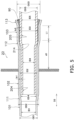
FIG. 5 is an enlarged cross-sectional view illustrating an example of the pipe coupling structure. -
FIG. 1 illustrates anair conditioner 1 as an example of a refrigeration cycle apparatus to which a pipe coupling structure is applied. In the present disclosure, the case where the refrigeration cycle apparatus is theair conditioner 1 will be described, but the refrigeration cycle apparatus is not limited to theair conditioner 1. The refrigeration cycle apparatus is an apparatus that performs a refrigeration cycle. Examples of the refrigeration cycle apparatus include a refrigerator, a freezer, a water heater, a floor heating apparatus, and a heat pump apparatus. - The
air conditioner 1 inFIG. 1 includes acompressor 2, a four-way valve 3, anoutdoor heat exchanger 4, an expansion valve 5, anindoor heat exchanger 6, an outdoor fan 7, and anindoor fan 8. - The
compressor 2, the four-way valve 3, theoutdoor heat exchanger 4, the expansion valve 5, and theindoor heat exchanger 6 are connected by a communicatingtube 11 to form arefrigerant circuit 10. In therefrigerant circuit 10, a refrigerant circulates and a vapor compression refrigeration cycle is repeated. In other words, the refrigerant circulates in therefrigerant circuit 10 while alternating between decompression expansion and heat dissipation condensation. Examples of the refrigerant used in therefrigerant circuit 10 in which the vapor compression refrigeration cycle is performed include a hydrofluorocarbon (HFC)-based refrigerant, a hydrofluoroolefin (HFO), an unsaturated HFC-based refrigerant, and a natural refrigerant. Examples of the HFC-based refrigerant include R32, R410A, R407C, and R134a. Examples of the HFO include R1234ze and R1234yf. The natural refrigerant is, for example, R717. - The flow path of the refrigerant flowing in the
refrigerant circuit 10 is switched by the four-way valve 3. Theair conditioner 1 can switch between cooling operation and heating operation by switching the flow path with the four-way valve 3. During the cooling operation, the refrigerant flows through thecompressor 2, the four-way valve 3, theoutdoor heat exchanger 4, the expansion valve 5, theindoor heat exchanger 6, the four-way valve 3, and then thecompressor 2 in this order. During the heating operation, the refrigerant flows through thecompressor 2, the four-way valve 3, theindoor heat exchanger 6, the expansion valve 5, theoutdoor heat exchanger 4, the four-way valve 3, and then thecompressor 2 in this order. - The
outdoor heat exchanger 4 and theindoor heat exchanger 6 are fin-and-tube heat exchangers. During the cooling operation, theoutdoor heat exchanger 4 functions as a condenser, and theindoor heat exchanger 6 functions as an evaporator. During the heating operation, theoutdoor heat exchanger 4 functions as an evaporator, and theindoor heat exchanger 6 functions as a condenser. -
FIG. 2 schematically illustrates a configuration of theoutdoor heat exchanger 4. Theoutdoor heat exchanger 4 includes a first inlet/outlet 41, aheader collecting tube 42, a plurality of connectingtubes 200, a plurality ofheat transfer tubes 100, a U-tube 45, a plurality ofheat transfer fins 300, aflow divider 48, and a second inlet/outlet 49. - In the
outdoor heat exchanger 4 functioning as a condenser, the refrigerant discharged from thecompressor 2 enters theoutdoor heat exchanger 4 through the first inlet/outlet 41. In theoutdoor heat exchanger 4 functioning as an evaporator, the refrigerant subjected to heat exchange in theindoor heat exchanger 6 exits theoutdoor heat exchanger 4 through the first inlet/outlet 41. Regardless of whether theoutdoor heat exchanger 4 functions as a condenser or an evaporator, the refrigerant passing through the first inlet/outlet 41 is mainly gasified refrigerant. - The
header collecting tube 42 is connected to the first inlet/outlet 41 and the plurality of connectingtubes 200. In theoutdoor heat exchanger 4 functioning as a condenser, the refrigerant entering through the first inlet/outlet 41 is distributed by theheader collecting tube 42 and flows into the plurality of connectingtubes 200. In theoutdoor heat exchanger 4 functioning as an evaporator, the refrigerant flowing through the plurality of connectingtubes 200 merges at theheader collecting tube 42 and flows into the first inlet/outlet 41. The connectingtubes 200 are connected to theheat transfer tubes 100. The 56heat transfer tubes 100 of theoutdoor heat exchanger 4, indicated by circles inFIG. 2 , are arranged in 2 columns and 26 rows. The number and array of theheat transfer tubes 100 of theoutdoor heat exchanger 4 to which the technology according to the present disclosure is applied are not limited to the array illustrated inFIG. 2 . Note that the rows are aligned in the gravity direction D1, and the columns are aligned in the horizontal direction D2, as indicated by arrows inFIG. 2 . -
FIG. 2 illustrates a circular cross section of theheat transfer tubes 100. In other words, theheat transfer tubes 100 extend in a direction perpendicular to the paper surface ofFIG. 2 . TheU-tube 45 is connected to the end of theheat transfer tube 100 to which the connectingtube 200 is not connected. TheU-tube 45 connects twoheat transfer tubes 100. TheU-tube 45 allows the refrigerant flowing in oneheat transfer tube 100 to turn around at the end of theoutdoor heat exchanger 4 and flow into the otherheat transfer tube 100. InFIG. 2 , theU-tube 45 indicated by a solid line is disposed in the front, and theU-tube 45 indicated by a broken line is disposed in the back. Allheat transfer tubes 100 penetrate vertically through the plurality ofheat transfer fins 300. The plurality ofheat transfer fins 300 are arranged such that the main surfaces thereof are parallel to each other. - The plurality of
heat transfer tubes 100 and theflow divider 48 are connected by the plurality of connectingtubes 200. When theoutdoor heat exchanger 4 inFIG. 2 functions as a condenser, the refrigerant flows into theflow divider 48 from sixheat transfer tubes 100 through six connectingtubes 200. The refrigerant that has flowed into theflow divider 48 from the six connectingtubes 200 and merged at theflow divider 48 flows out from one connectingtube 200. In theoutdoor heat exchanger 4 functioning as an evaporator, the refrigerant flowing into theflow divider 48 from one connectingtube 200 is distributed to the six connectingtubes 200 by theflow divider 48. Between one connectingtube 200 of theflow divider 48 and the second inlet/outlet 49, the plurality ofheat transfer tubes 100, the plurality of U-tubes 45, and one connectingtube 200 are connected in series. -
FIG. 3 schematically illustrates a configuration of theindoor heat exchanger 6. Theindoor heat exchanger 6 includes a connectingtube 200, a plurality ofheat transfer tubes 100, a U-tube 63, a plurality ofheat transfer fins 300, a plurality of connectingtubes 200, afirst flow divider 66, asecond flow divider 67, and an inlet/outlet pipe 68. - In the
indoor heat exchanger 6 functioning as a condenser, the refrigerant discharged from thecompressor 2 enters theheat transfer tubes 100 through the connectingtube 200. In theindoor heat exchanger 6 functioning as an evaporator, the refrigerant subjected to heat exchange in theindoor heat exchanger 6 exits theindoor heat exchanger 6 through the connectingtube 200. Regardless of whether theindoor heat exchanger 6 functions as a condenser or an evaporator, the refrigerant passing through the connectingtube 200 is mainly gasified refrigerant. - The connecting
tube 200 is connected to the inlet/outlet (not illustrated) of theindoor heat exchanger 6 and theheat transfer tubes 100. The 28heat transfer tubes 100 of theindoor heat exchanger 6, indicated by circles inFIG. 3 , are arranged in two columns. The number and array of theheat transfer tubes 100 of theindoor heat exchanger 6 to which the technology according to the present disclosure is applied are not limited to the array illustrated inFIG. 3 . Note that theindoor heat exchangers 6 are arranged in rows close to and far from across-flow fan 12 inFIG. 3 . -
FIG. 3 illustrates a circular cross section of theheat transfer tubes 100. In other words, theheat transfer tubes 100 extend in a direction perpendicular to the paper surface ofFIG. 3 . TheU-tube 63 is connected to the end of theheat transfer tube 100 to which the connectingtube 200 is not connected. TheU-tube 63 connects twoheat transfer tubes 100. TheU-tube 63 allows the refrigerant flowing in oneheat transfer tube 100 to turn around at the end of theindoor heat exchanger 6 and flow into the otherheat transfer tube 100. - In
FIG. 3 , theU-tube 63 indicated by a solid line is disposed in the front, and theU-tube 63 indicated by a broken line is disposed in the back. Allheat transfer tubes 100 penetrate vertically through the plurality ofheat transfer fins 300. The plurality ofheat transfer fins 300 are arranged such that the main surfaces thereof are parallel to each other. - One
heat transfer tube 100 and thefirst flow divider 66 are connected by one connectingtube 200. When theindoor heat exchanger 6 inFIG. 3 functions as a condenser, the refrigerant flows into thefirst flow divider 66 from oneheat transfer tube 100 through one connectingtube 200. The refrigerant flows into thefirst flow divider 66 from one connectingtube 200 and is distributed to two connectingtubes 200 by thefirst flow divider 66. In theindoor heat exchanger 6 functioning as an evaporator, the refrigerant flowing into thefirst flow divider 66 from two connectingtubes 200 merges at thefirst flow divider 66 and flows out from one connectingtube 200 into theheat transfer tube 100. - Between the two connecting
tubes 200 connected to thefirst flow divider 66 and the two connectingtubes 200 connected to thesecond flow divider 67, two flow paths are formed by the plurality ofheat transfer tubes 100 and the plurality of U-tubes 63 connected in series. - Two
heat transfer tubes 100 and thesecond flow divider 67 are connected by the two connectingtubes 200. When theindoor heat exchanger 6 illustrated inFIG. 3 functions as an evaporator, the refrigerant flowing into thesecond flow divider 67 from one inlet/outlet pipe 68 is distributed to the two connectingtubes 200 by thesecond flow divider 67, and flows out from the two connectingtubes 200 to the twoheat transfer tubes 100. When theindoor heat exchanger 6 functions as a condenser, the refrigerant flows into thesecond flow divider 67 from the twoheat transfer tubes 100 through the two connectingtubes 200. The refrigerant flowing into thesecond flow divider 67 from the two connectingtubes 200 merges at thefirst flow divider 66 and flows out from one inlet/outlet pipe 68. -
FIG. 4 illustrates a cross section of apipe coupling structure 20. Thepipe coupling structure 20 is the structure of the area where aheat transfer tube 100 and a connectingtube 200 are coupled together. Theheat transfer tube 100 is a first refrigerant pipe having afirst portion 101, afirst expansion portion 111, asecond portion 102, asecond expansion portion 112, and athird portion 103 arranged in order. Theheat transfer tube 100 is expanded in the first stage from thefirst portion 101 through thefirst expansion portion 111 to thesecond portion 102. Furthermore, theheat transfer tube 100 is expanded in the second stage from thesecond portion 102 through thesecond expansion portion 112 to thethird portion 103. This two-stage expansion of theheat transfer tube 100 is performed, for example, by flaring. The connectingtube 200 is inserted into theheat transfer tube 100 serving as the first refrigerant pipe. The connectingtube 200 is a second refrigerant pipe having afourth portion 204 that faces thesecond portion 102 of theheat transfer tube 100 and afifth portion 205 that faces thethird portion 103 of theheat transfer tube 100. - An inner diameter ID2 of the
second portion 102 of theheat transfer tube 100 is larger than an inner diameter ID1 of thefirst portion 101. In addition, an inner diameter ID3 of thethird portion 103 of theheat transfer tube 100 is larger than the inner diameter ID2 of thesecond portion 102. An outer diameter OD2 of thesecond portion 102 is larger than an outer diameter OD1 of thefirst portion 101. In addition, an outer diameter OD3 of thethird portion 103 is larger than the outer diameter OD2 of thesecond portion 102. Furthermore, the thickness of theheat transfer tube 100 is the same in thefirst portion 101, thesecond portion 102, and thethird portion 103. Thefirst expansion portion 111 of theheat transfer tube 100 is the area of theheat transfer tube 100, the inner diameter of which gradually changes from the inner diameter ID1 of thefirst portion 101 to the inner diameter ID2 of thesecond portion 102. Thesecond expansion portion 112 of theheat transfer tube 100 is the area of theheat transfer tube 100, the inner diameter of which gradually changes from the inner diameter ID2 of thesecond portion 102 to the inner diameter ID3 of thethird portion 103. - An outer diameter OD5 of the
fifth portion 205 of the connectingtube 200 is larger than an outer diameter OD4 of thefourth portion 204. In addition, an inner diameter ID5 of thefifth portion 205 of the connectingtube 200 is larger than an inner diameter ID4 of thefourth portion 204. Furthermore, the thickness of the connectingtube 200 is the same in thefourth portion 204 and thefifth portion 205. Thefourth portion 204 of the connectingtube 200 is formed, for example, by narrowing the outer diameter OD5 of the fifth portion 105 to the outer diameter OD4. For example, thefourth portion 204 can be narrowed by swaging thefourth portion 204. - The
heat transfer tube 100 is formed from, for example, aluminum, an aluminum alloy, or copper. Theheat transfer tube 100 formed from aluminum or aluminum alloy is preferable in that the weight of theoutdoor heat exchanger 4 or theindoor heat exchanger 6 can be reduced. In addition, the connectingtube 200 is formed from, for example, aluminum, an aluminum alloy, or copper. The connectingtube 200 formed from aluminum or aluminum alloy is preferable in that the weight of theoutdoor heat exchanger 4 or theindoor heat exchanger 6 can be reduced. The thickness of the heat transfer tube 100 (first refrigerant pipe) is thinner than the thickness of the connecting tube 200 (second refrigerant pipe). This thin-walledheat transfer tube 100 is reinforced by the overlap with the connectingtube 200. - In the
pipe coupling structure 20, thefifth portion 205 of the connectingtube 200 and thethird portion 103 of theheat transfer tube 100 are brazed together. The total length of thesecond portion 102, thesecond expansion portion 112, and thethird portion 103 is, for example, within the range of 15 mm to 25 mm. The length of thethird portion 103 is, for example, within the range of 3 mm to 10 mm. The end of the fourth portion 104 is preferably inserted to the vicinity of the boundary between thefirst expansion portion 111 and thesecond portion 102. The length of thesecond portion 102 of theheat transfer tube 100 is longer than the length of thefourth portion 204 of the connectingtube 200. - A first gap In1 between the
second portion 102 of theheat transfer tube 100 and thefourth portion 204 of the connectingtube 200 is larger than a second gap In2 between thethird portion 103 of theheat transfer tube 100 and thefifth portion 205 of the connectingtube 200. By making the first gap In1 larger than the second gap In2, it is easier to insert the connectingtube 200 into theheat transfer tube 100. - The
heat transfer tube 100 has athird expansion portion 113 connected to thethird portion 103 and expanded in a tapered shape from thethird portion 103. Since thethird expansion portion 113 is expanded in the tapered shape, the gap between thethird expansion portion 113 and thefifth portion 205 of the connectingtube 200 is even wider than the second gap In2. Abrazing filler metal 90 is poured through the gap between the expandedthird expansion portion 113 and thefifth portion 205. The tapered expansion of thethird expansion portion 113 facilitates brazing. - As illustrated in
FIG. 4 , the entirefirst portion 101 of theheat transfer tube 100 penetrates theheat transfer fins 300. In addition,part 102a of thesecond portion 102 of theheat transfer tube 100 penetrates theheat transfer fins 300. Thepart 102a of thesecond portion 102 is the area of thesecond portion 102 which is closer to thefirst expansion portion 111 than thesecond expansion portion 112. Theother part 102b of thesecond portion 102 is the area of thesecond portion 102 other than thepart 102a and thetube plate 350. Theother part 102b of thesecond portion 102 is the area of thesecond portion 102 closer to thesecond expansion portion 112. Theother part 102b of thesecond portion 102 is not in contact with theheat transfer fins 300. In addition, thethird portion 103 of theheat transfer tube 100 is also not in contact with theheat transfer fins 300. As illustrated inFIG. 4 , thesecond portion 102 of theheat transfer tube 100 is in contact with thetube plate 350. More specifically, thesecond portion 102 is in contact with thetube plate 350 between thepart 102a and theother part 102b of thesecond portion 102. - A distance di1 along the tube axis direction D3 from the
third portion 103 to thetube plate 350 is greater than a length L1 of thethird portion 103 along the tube axis direction D3. In addition, the distance di1 along the tube axis direction D3 from thethird portion 103 to thetube plate 350 is greater than the outer diameter OD3 of thethird portion 103. - The ratio of the inner diameter ID3 of the
third portion 103 to the inner diameter ID2 of thesecond portion 102 is smaller than the ratio of the inner diameter ID2 of thesecond portion 102 to the inner diameter ID2 of thefirst portion 101. In other words, the relationship of (ID3/ID2) < (ID2/ID1) holds. It is preferable that 1.02 ≥ ID3/ID2 ≥ 1.08. In addition, the ratio of the outer diameter OD3 of thethird portion 103 to the outer diameter OD2 of thesecond portion 102 is smaller than the ratio of the outer diameter OD2 of thesecond portion 102 to the outer diameter OD2 of thefirst portion 101. In other words, the relationship of (OD3/OD2) < (OD2/OD1) holds. The inner diameter ID1 of thefirst portion 101 is 5 mm or less. - The connecting
tube 200 has afourth expansion portion 214 between thefourth portion 204 and thefifth portion 205. Thefourth expansion portion 214 is the area of the connectingtube 200, the outer diameter of which gradually changes from the outer diameter OD4 of thefourth portion 204 to the outer diameter OD5 of thefifth portion 205. Thefourth expansion portion 214 is in contact with thesecond expansion portion 112. - The contact between the
fourth expansion portion 214 and thesecond expansion portion 112 enables positioning of theheat transfer tube 100 and the connectingtube 200 in the tube axis direction D3. In addition, the contact between thefourth expansion portion 214 and thesecond expansion portion 112 prevents thebrazing filler metal 90 from entering the first gap In1 between thesecond portion 102 of theheat transfer tube 100 and thefourth portion 204 of the connectingtube 200. Therefore, the inner surface of thesecond portion 102 and the outer surface of thefourth portion 204 are not brazed. - (3-1)
In thepipe coupling structure 20, thesecond portion 102 of theheat transfer tube 100 serving as a first refrigerant pipe and thefourth portion 204 of the connectingtube 200 serving as a second refrigerant pipe face each other. In this manner, thesecond portion 102 and thefourth portion 204 face each other, thereby allowing an improvement in the strength of the coupling area. Thethird portion 103 of theheat transfer tube 100 and thefifth portion 205 of the connectingtube 200 are brazed together, but thesecond portion 102 of theheat transfer tube 100 and thefourth portion 204 of the connectingtube 200 are not brazed. Thus, thepipe coupling structure 20 can prevent defects caused by an increase in the brazed area. - (3-2)
In thepipe coupling structure 20, the first gap In1 between thesecond portion 102 of theheat transfer tube 100 and thefourth portion 204 of the connectingtube 200 is larger than the second gap In2 between thethird portion 103 of theheat transfer tube 100 and thefifth portion 205 of the connectingtube 200. This structure makes it easier to insert thefourth portion 204 of the connectingtube 200 into thesecond portion 102 of theheat transfer tube 100, and to couple the pipes. - (3-3)
Thethird expansion portion 113 of thepipe coupling structure 20 is expanded in a tapered shape from thethird portion 103. Thethird expansion portion 113, which is expanded in the tapered shape in this manner, facilitates the insertion of the connectingtube 200 into theheat transfer tube 100. In addition, thebrazing filler metal 90 can be easily poured through thethird expansion portion 113 expanded in the tapered shape. - (3-4)
In thepipe coupling structure 20, the first refrigerant pipe is theheat transfer tube 100 of theoutdoor heat exchanger 4 or theindoor heat exchanger 6. Thefirst portion 101 and thepart 102a of thesecond portion 102 of theheat transfer tube 100 penetrate theheat transfer fins 300. With this structure, thefirst portion 101 and thepart 102a of thesecond portion 102 are supported by theheat transfer fins 300. As a result, the stress on thefirst portion 101 of theheat transfer tube 100 caused by the stress on the connectingtube 200 serving as the second refrigerant pipe can be reduced. The reduced stress on thefirst portion 101 makes it less likely to occur the damage in thepipe coupling structure 20. - (3-5)
In thepipe coupling structure 20, thesecond portion 102 is in contact with thetube plate 350 of theoutdoor heat exchanger 4 or theindoor heat exchanger 6. Thesecond portion 102 is a non-brazed area, and even if thetube plate 350 is in contact with thesecond portion 102, defects such as difficulty in brazing due to escape of heat during brazing to thetube plate 350 are less likely to occur. Even if heat is transferred from thefirst portion 101 to thesecond portion 102 by brazing in thefirst portion 101, heat escapes to thetube plate 350, thereby allowing a reduction in the risk of deterioration of theheat transfer fins 300 due to exposure to the heat of brazing. - (3-6)
In thepipe coupling structure 20, theother part 102b of thesecond portion 102 and thethird portion 103 are not in contact with theheat transfer fins 300. Since thepipe coupling structure 20 has this structure, it is possible to prevent heat from escaping to theheat transfer fins 300 during the brazing of thethird portion 103. As a result, it becomes easier to perform good brazing between thefirst portion 101 of theheat transfer tube 100 and thefifth portion 205 of the connectingtube 200. - (3-7)
In thepipe coupling structure 20, the distance di1 along the tube axis direction D3 from thethird portion 103 to thetube plate 350 is greater than the length L1 of thethird portion 103 along the tube axis direction D3. Since the distance di1 from thethird portion 103 to thetube plate 350 makes it difficult for the brazing heat to be transferred to theheat transfer fins 300, it is possible to suppress the deterioration of theheat transfer fins 300 due to the influence of the brazing heat. - (3-8)
In thepipe coupling structure 20, the distance di1 along the tube axis direction D3 from thethird portion 103 to thetube plate 350 is greater than the outer diameter OD3 of thethird portion 103. Since the distance di1 from thethird portion 103 to thetube plate 350 makes it difficult for the brazing heat to be transferred to theheat transfer fins 300, it is possible to suppress the deterioration of theheat transfer fins 300 due to the influence of the brazing heat. - (3-9)
External stress may be applied to the connectingtube 200 connected to the second inlet/outlet 49 of theoutdoor heat exchanger 4 inFIG. 2 and the connectingtube 200 connected to the inlet/outlet (not illustrated) of theindoor heat exchanger 6 inFIG. 3 . However, such connectingtube 200 connected to the outlet or inlet is reinforced by thepipe coupling structure 20, which contributes to improvement of the durability of theoutdoor heat exchanger 4 or theindoor heat exchanger 6. - (3-10)
The thickness of theheat transfer tube 100 serving as the first refrigerant pipe is thinner than the thickness of the connectingtube 200 serving as the second refrigerant pipe. By reducing the thickness of theheat transfer tube 100, the heat of the refrigerant is more easily transferred to theheat transfer fins 300, and the performance of theoutdoor heat exchanger 4 and theindoor heat exchanger 6 can be improved. Meanwhile, the decrease in the strength of theheat transfer tube 100 having a thinner wall thickness can be compensated for by overlapping with the connectingtube 200 having a thicker wall thickness. - (3-11)
In thepipe coupling structure 20, the ratio of the inner diameter ID3 of thethird portion 103 to the inner diameter ID2 of thesecond portion 102 is smaller than the ratio of the inner diameter ID2 of thesecond portion 102 to the inner diameter ID1 of thefirst portion 101. As described above, the tube expansion rate (ID3/ID2) from thesecond portion 102 to thethird portion 103 is reduced to such an extent that allows positioning when inserting the connectingtube 200 into theheat transfer tube 100, so that theheat transfer tube 100 and the connectingtube 200 are easy to manufacture. - (3-12)
In thepipe coupling structure 20, the inner diameter ID1 of thefirst portion 101 is 5 mm or less. Even if the thinheat transfer tube 100 of 5 mm or less is used, thepipe coupling structure 20 requires only a small amount of drawing, and can suppress an increase in pressure loss caused by the flow of the refrigerant and the generation of refrigerant noise. - (3-13)
In thepipe coupling structure 20, thefourth expansion portion 214 of the connectingtube 200 serving as the second refrigerant pipe is in contact with thesecond expansion portion 112 of theheat transfer tube 100 serving as the first refrigerant pipe. Positioning by the contact between thefourth expansion portion 214 and thesecond expansion portion 112 enables accurate positioning. - (3-14)
The length of the second portion of theheat transfer tube 100 is longer than the length of thefourth portion 204 of the connectingtube 200. With this structure, when inserting the connectingtube 200 into theheat transfer tube 100, thefourth expansion portion 214 of the connectingtube 200 abuts on thesecond expansion portion 112 of theheat transfer tube 100 before the leading end of thefourth portion 204 abuts on thefirst expansion portion 111 of theheat transfer tube 100. As described above, since thesecond portion 102 is longer than thefourth portion 204, it is possible to prevent a situation in which the connectingtube 200 cannot be sufficiently inserted into theheat transfer tube 100. - (3-15)
If theheat transfer tube 100 is formed from aluminum or an aluminum alloy, the strength of the soft aluminum or aluminum alloy can be reinforced by thesecond portion 102 and thefourth portion 204 that face each other and thethird portion 103 and thefifth portion 205 that face each other, while using lightweight aluminum or aluminum alloy, thereby making it less likely to cause damage. Similarly, if the connectingtube 200 is formed from aluminum or an aluminum alloy, the strength of the soft aluminum or aluminum alloy can be reinforced by thesecond portion 102 and thefourth portion 204 that face each other and thethird portion 103 and thefifth portion 205 that face each other, while using lightweight aluminum or aluminum alloy, thereby making it less likely to cause damage. In particular, if theheat transfer tube 100 and the connectingtube 200 are formed from the same aluminum or the same aluminum alloy, the electrolytic corrosion that occurs between dissimilar metals can be prevented. - Although the embodiment of the present disclosure have been described above, it will be understood that various changes in form and details can be made without departing from the spirit and scope of the present disclosure described in the claims.
-
- 1: air conditioner (example of refrigeration cycle apparatus)
- 4: outdoor heat exchanger (example of heat exchanger)
- 6: indoor heat exchanger (example of heat exchanger)
- 20: pipe coupling structure
- 100: heat transfer tube (example of first refrigerant pipe)
- 101: first portion
- 102: second portion
- 102a: part of second portion
- 102b: other part of second portion
- 103: third portion
- 111: first expansion portion
- 112: second expansion portion
- 113: third expansion portion
- 200: connecting tube (example of second refrigerant pipe)
- 204: fourth portion
- 205: fifth portion
- 214: fourth expansion portion
- 300: heat transfer fin
- 350: tube plate
- Patent Literature 1:
JP 2001-116480 A
Claims (16)
- A pipe coupling structure (20) comprising:a first refrigerant pipe (100) that has a first portion (101), a first expansion portion (111), a second portion (102), a second expansion portion (112), and a third portion (103) arranged in order; anda second refrigerant pipe (200) that is inserted into the first refrigerant pipe and has a fourth portion (204) facing the second portion and a fifth portion (205) facing the third portion, whereinthe second portion has an inner diameter larger than an inner diameter of the first portion, and the third portion has an inner diameter larger than the inner diameter of the second portion,the first expansion portion is an area of the first refrigerant pipe, an inner diameter of which gradually changes from the inner diameter of the first portion to the inner diameter of the second portion,the second expansion portion is an area of the first refrigerant pipe, an inner diameter of which gradually changes from the inner diameter of the second portion to the inner diameter of the third portion,the fifth portion has an outer diameter larger than an outer diameter of the fourth portion, andthe fifth portion and the third portion are brazed.
- The pipe coupling structure (20) according to claim 1, wherein
a first gap between the second portion and the fourth portion is larger than a second gap between the third portion and the fifth portion. - The pipe coupling structure (20) according to claim 1 or 2, wherein
the first refrigerant pipe has a third expansion portion (113) connected to the third portion and expanded in a tapered shape from the third portion. - The pipe coupling structure (20) according to any one of claims 1 to 3, wherein
the first refrigerant pipe is a heat transfer tube (100) of a heat exchanger (4, 6), and the first portion and part (102a) of the second portion penetrate a heat transfer fin (300). - The pipe coupling structure (20) according to claim 4, wherein
the second portion is in contact with a tube plate (350) of the heat exchanger. - The pipe coupling structure (20) according to claim 4 or 5, wherein
the other part (102b) of the second portion and the third portion are not in contact with the heat transfer fin. - The pipe coupling structure (20) according to claim 5, wherein
a distance along a tube axis direction from the third portion to the tube plate is greater than a length of the third portion along the tube axis direction. - The pipe coupling structure (20) according to claim 5, wherein
a distance along a tube axis direction from the third portion to the tube plate is greater than an outer diameter of the third portion. - The pipe coupling structure (20) according to any one of claims 4 to 8, wherein
the second refrigerant pipe is disposed at an outlet or inlet of the heat exchanger. - The pipe coupling structure (20) according to any one of claims 4 to 9, wherein
the first refrigerant pipe has a thickness smaller than a thickness of the second refrigerant pipe. - The pipe coupling structure (20) according to any one of claims 1 to 10, wherein
a ratio of the inner diameter of the third portion to the inner diameter of the second portion is smaller than a ratio of the inner diameter of the second portion to the inner diameter of the first portion. - The pipe coupling structure (20) according to any one of claims 1 to 11, wherein
the inner diameter of the first portion is 5 mm or less. - The pipe coupling structure (20) according to any one of claims 1 to 12, whereinthe second refrigerant pipe has a fourth expansion portion (214) between the fourth portion and the fifth portion,the fourth expansion portion is an area of the second refrigerant pipe, an outer diameter of which gradually changes from the outer diameter of the fourth portion to the outer diameter of the fifth portion, andthe fourth expansion portion is in contact with the second expansion portion.
- The pipe coupling structure (20) according to any one of claims 1 to 13, wherein
the second portion has a length longer than a length of the fourth portion. - The pipe coupling structure (20) according to any one of claims 1 to 14, wherein
at least one of the first refrigerant pipe and the second refrigerant pipe is formed from aluminum or an aluminum alloy. - A refrigeration cycle apparatus (1) comprising:a refrigerant circuit (10) through which a refrigerant circulates; andthe pipe coupling structure according to any one of claims 1 to 15, provided in the refrigerant circuit.
Applications Claiming Priority (2)
| Application Number | Priority Date | Filing Date | Title |
|---|---|---|---|
| JP2021076060A JP7227512B2 (en) | 2021-04-28 | 2021-04-28 | Piping connection structure and refrigeration cycle device |
| PCT/JP2022/019318 WO2022230984A1 (en) | 2021-04-28 | 2022-04-28 | Pipe connection structure and refrigeration cycle device |
Publications (3)
| Publication Number | Publication Date |
|---|---|
| EP4332489A1 true EP4332489A1 (en) | 2024-03-06 |
| EP4332489A4 EP4332489A4 (en) | 2024-10-02 |
| EP4332489B1 EP4332489B1 (en) | 2025-08-06 |
Family
ID=83848583
Family Applications (1)
| Application Number | Title | Priority Date | Filing Date |
|---|---|---|---|
| EP22795897.2A Active EP4332489B1 (en) | 2021-04-28 | 2022-04-28 | Pipe connection structure and refrigeration cycle device |
Country Status (7)
| Country | Link |
|---|---|
| US (1) | US12055329B2 (en) |
| EP (1) | EP4332489B1 (en) |
| JP (1) | JP7227512B2 (en) |
| CN (1) | CN117242313A (en) |
| AU (1) | AU2022267168B2 (en) |
| ES (1) | ES3041813T3 (en) |
| WO (1) | WO2022230984A1 (en) |
Families Citing this family (8)
| Publication number | Priority date | Publication date | Assignee | Title |
|---|---|---|---|---|
| WO2024180179A1 (en) | 2023-03-02 | 2024-09-06 | Ceramtec Gmbh | Use of a lead-free piezo ceramic in devices requiring high permanent preload |
| KR20250006659A (en) * | 2023-07-04 | 2025-01-13 | 삼성전자주식회사 | Heat exchanger |
| CN119790269A (en) * | 2023-08-08 | 2025-04-08 | 日立江森自控空调有限公司 | Air conditioner |
| WO2025120791A1 (en) * | 2023-12-07 | 2025-06-12 | 日立ジョンソンコントロールズ空調株式会社 | Air conditioner |
| CN121175523A (en) * | 2024-01-29 | 2025-12-19 | 日立江森自控空调有限公司 | Indoor unit of air conditioner |
| JP7507994B1 (en) | 2024-03-12 | 2024-06-28 | 日立ジョンソンコントロールズ空調株式会社 | Air Conditioning Equipment |
| CN119330451B (en) * | 2024-12-06 | 2025-10-31 | 南京工业大学 | A treatment device for electroplating wastewater by evaporation separation |
| CN119492147B (en) * | 2025-01-17 | 2025-06-06 | 广东美的暖通设备有限公司 | Heat sink and heat source unit |
Family Cites Families (26)
| Publication number | Priority date | Publication date | Assignee | Title |
|---|---|---|---|---|
| US3957289A (en) * | 1974-08-19 | 1976-05-18 | Aluminum Company Of America | Soldered joint and method |
| JP3101353B2 (en) | 1991-08-09 | 2000-10-23 | 富士通株式会社 | Process parent-child relationship handover unit |
| JP3454647B2 (en) * | 1996-11-07 | 2003-10-06 | 東芝キヤリア株式会社 | Air conditioner |
| JP4300499B2 (en) * | 1999-10-15 | 2009-07-22 | 株式会社ティラド | Fin coil type heat exchanger and manufacturing method thereof |
| JP2001118480A (en) | 1999-10-20 | 2001-04-27 | Uchihashi Estec Co Ltd | Thin temperature fuse |
| JP4271209B2 (en) * | 2006-06-27 | 2009-06-03 | 株式会社東芝 | Clothes dryer |
| JP2008232201A (en) | 2007-03-19 | 2008-10-02 | Daikin Ind Ltd | Piping joint structure |
| JP5238428B2 (en) * | 2008-09-24 | 2013-07-17 | 東芝キヤリア株式会社 | Heat exchanger and air conditioner |
| JP2010117115A (en) | 2008-11-14 | 2010-05-27 | Daikin Ind Ltd | Pipe connecting structure |
| JP2011089710A (en) | 2009-10-22 | 2011-05-06 | Daikin Industries Ltd | Refrigerant heat exchanger |
| JP2013164215A (en) * | 2012-02-10 | 2013-08-22 | Mitsubishi Heavy Ind Ltd | Fin tube-type heat exchanger |
| JP5738781B2 (en) * | 2012-02-10 | 2015-06-24 | ダイキン工業株式会社 | Air conditioner |
| JP6050671B2 (en) * | 2012-12-07 | 2016-12-21 | ダイキン工業株式会社 | Method of manufacturing piping unit of air conditioner and method of installing air conditioner |
| PL2784207T3 (en) * | 2013-03-29 | 2017-07-31 | Electrolux Appliances Aktiebolag | A method for assembling a laundry dryer including a heat pump system with a closed refrigerant circuit and a heat pump laundry dryer with a closed refrigerant circuit |
| JP2015078789A (en) * | 2013-10-16 | 2015-04-23 | 三菱電機株式会社 | Heat exchanger and air conditioning device including heat exchanger |
| KR20150053135A (en) * | 2013-11-07 | 2015-05-15 | 엘지전자 주식회사 | Heat exchanger and Manufacturing method fo the same |
| JP5999083B2 (en) | 2013-12-27 | 2016-09-28 | ダイキン工業株式会社 | HEAT EXCHANGE DEVICE AND METHOD OF PRODUCING HEAT EXCHANGE DEVICE |
| JP5861723B2 (en) | 2014-01-30 | 2016-02-16 | ダイキン工業株式会社 | Air conditioner indoor unit |
| JP2015217400A (en) | 2014-05-14 | 2015-12-07 | 日立アプライアンス株式会社 | Method for production of different-and small-diameter copper tube, and different-and small-diameter copper tube |
| JP2016014495A (en) * | 2014-07-01 | 2016-01-28 | ダイキン工業株式会社 | Flowing film evaporator |
| US10697568B2 (en) * | 2014-09-25 | 2020-06-30 | Mitsubishi Electric Corporation | Refrigerant pipe, method of manufacturing the refrigerant pipe, and heat exchanger including the refrigerant pipe |
| WO2016103487A1 (en) * | 2014-12-26 | 2016-06-30 | 三菱電機株式会社 | Heat exchanger and air-conditioning device |
| JP2017201220A (en) * | 2016-05-02 | 2017-11-09 | 株式会社富士通ゼネラル | Heat exchanger |
| JP6719394B2 (en) | 2017-01-16 | 2020-07-08 | 日立ジョンソンコントロールズ空調株式会社 | Connection piping structure of heat exchanger and air conditioner |
| US11193701B2 (en) * | 2017-06-09 | 2021-12-07 | Mitsubishi Electric Corporation | Heat exchanger and refrigeration cycle apparatus |
| JP6721546B2 (en) * | 2017-07-21 | 2020-07-15 | ダイキン工業株式会社 | Refrigeration equipment |
-
2021
- 2021-04-28 JP JP2021076060A patent/JP7227512B2/en active Active
-
2022
- 2022-04-28 CN CN202280030758.2A patent/CN117242313A/en active Pending
- 2022-04-28 AU AU2022267168A patent/AU2022267168B2/en active Active
- 2022-04-28 ES ES22795897T patent/ES3041813T3/en active Active
- 2022-04-28 EP EP22795897.2A patent/EP4332489B1/en active Active
- 2022-04-28 WO PCT/JP2022/019318 patent/WO2022230984A1/en not_active Ceased
-
2023
- 2023-10-23 US US18/382,555 patent/US12055329B2/en active Active
Also Published As
| Publication number | Publication date |
|---|---|
| CN117242313A (en) | 2023-12-15 |
| JP2022170142A (en) | 2022-11-10 |
| WO2022230984A1 (en) | 2022-11-03 |
| JP7227512B2 (en) | 2023-02-22 |
| US20240044557A1 (en) | 2024-02-08 |
| AU2022267168B2 (en) | 2025-03-13 |
| AU2022267168A1 (en) | 2023-11-30 |
| EP4332489A4 (en) | 2024-10-02 |
| US12055329B2 (en) | 2024-08-06 |
| EP4332489B1 (en) | 2025-08-06 |
| ES3041813T3 (en) | 2025-11-14 |
Similar Documents
| Publication | Publication Date | Title |
|---|---|---|
| EP4332489B1 (en) | Pipe connection structure and refrigeration cycle device | |
| US9322602B2 (en) | Heat exchanger having a plurality of plate-like fins and a plurality of flat-shaped heat transfer pipes orthogonal to the plate-like fins | |
| EP2565561B1 (en) | Heat exchanging device and connecting tube used therein | |
| JP2008215733A (en) | Fin and tube type heat exchanger | |
| US9279624B2 (en) | Heat exchanger tube with collared fins for enhanced heat transfer | |
| EP3637033B1 (en) | Heat exchanger and refrigeration cycle device | |
| CN105143808A (en) | Heat exchanger, refrigeration cycle device and method for manufacturing heat exchanger | |
| JP2006071270A (en) | Heat exchanger, intermediate heat exchanger, and refrigeration cycle | |
| JP5911597B2 (en) | Flat shape heat transfer tube, method of manufacturing cross fin tube type heat exchanger equipped with the same, cross fin tube type heat exchanger manufactured by the method | |
| CN104040281A (en) | Air conditioner | |
| US12104862B2 (en) | Heat exchanger and air-conditioning apparatus | |
| US11959648B2 (en) | Heat exchanger and air conditioning apparatus | |
| JP2013164215A (en) | Fin tube-type heat exchanger | |
| JPWO2017208419A1 (en) | Fin tube type heat exchanger and heat pump device provided with the fin tube type heat exchanger | |
| JP5063765B2 (en) | Heat exchanger, heat exchanger manufacturing method, refrigerator, and air conditioner | |
| JP5595343B2 (en) | Heat exchanger, refrigeration cycle circuit using the same, refrigerator using the refrigeration cycle circuit, and air conditioner | |
| JP2007078252A (en) | Heat exchanger | |
| JP7290396B2 (en) | Heat exchanger | |
| WO2025163700A1 (en) | Indoor unit of air conditioner |
Legal Events
| Date | Code | Title | Description |
|---|---|---|---|
| STAA | Information on the status of an ep patent application or granted ep patent |
Free format text: STATUS: THE INTERNATIONAL PUBLICATION HAS BEEN MADE |
|
| PUAI | Public reference made under article 153(3) epc to a published international application that has entered the european phase |
Free format text: ORIGINAL CODE: 0009012 |
|
| STAA | Information on the status of an ep patent application or granted ep patent |
Free format text: STATUS: REQUEST FOR EXAMINATION WAS MADE |
|
| 17P | Request for examination filed |
Effective date: 20231114 |
|
| AK | Designated contracting states |
Kind code of ref document: A1 Designated state(s): AL AT BE BG CH CY CZ DE DK EE ES FI FR GB GR HR HU IE IS IT LI LT LU LV MC MK MT NL NO PL PT RO RS SE SI SK SM TR |
|
| DAV | Request for validation of the european patent (deleted) | ||
| DAX | Request for extension of the european patent (deleted) | ||
| P01 | Opt-out of the competence of the unified patent court (upc) registered |
Free format text: CASE NUMBER: APP_38454/2024 Effective date: 20240627 |
|
| A4 | Supplementary search report drawn up and despatched |
Effective date: 20240904 |
|
| RIC1 | Information provided on ipc code assigned before grant |
Ipc: F16L 13/02 20060101ALN20240829BHEP Ipc: F28D 1/04 20060101ALI20240829BHEP Ipc: F28F 9/26 20060101ALI20240829BHEP Ipc: F28F 9/02 20060101ALI20240829BHEP Ipc: F28D 1/047 20060101ALI20240829BHEP Ipc: F25B 41/42 20210101ALI20240829BHEP Ipc: F25B 39/04 20060101ALI20240829BHEP Ipc: F25B 39/02 20060101ALI20240829BHEP Ipc: F25B 13/00 20060101ALI20240829BHEP Ipc: F16L 13/08 20060101ALI20240829BHEP Ipc: F28F 9/18 20060101ALI20240829BHEP Ipc: F25B 41/40 20210101ALI20240829BHEP Ipc: F16L 47/02 20060101ALI20240829BHEP Ipc: B23K 1/00 20060101ALI20240829BHEP Ipc: F28F 1/00 20060101AFI20240829BHEP |
|
| GRAP | Despatch of communication of intention to grant a patent |
Free format text: ORIGINAL CODE: EPIDOSNIGR1 |
|
| STAA | Information on the status of an ep patent application or granted ep patent |
Free format text: STATUS: GRANT OF PATENT IS INTENDED |
|
| RIC1 | Information provided on ipc code assigned before grant |
Ipc: F16L 13/02 20060101ALN20250205BHEP Ipc: F28D 1/04 20060101ALI20250205BHEP Ipc: F28F 9/26 20060101ALI20250205BHEP Ipc: F28F 9/02 20060101ALI20250205BHEP Ipc: F28D 1/047 20060101ALI20250205BHEP Ipc: F25B 41/42 20210101ALI20250205BHEP Ipc: F25B 39/04 20060101ALI20250205BHEP Ipc: F25B 39/02 20060101ALI20250205BHEP Ipc: F25B 13/00 20060101ALI20250205BHEP Ipc: F16L 13/08 20060101ALI20250205BHEP Ipc: F28F 9/18 20060101ALI20250205BHEP Ipc: F25B 41/40 20210101ALI20250205BHEP Ipc: F16L 47/02 20060101ALI20250205BHEP Ipc: B23K 1/00 20060101ALI20250205BHEP Ipc: F28F 1/00 20060101AFI20250205BHEP |
|
| INTG | Intention to grant announced |
Effective date: 20250213 |
|
| GRAS | Grant fee paid |
Free format text: ORIGINAL CODE: EPIDOSNIGR3 |
|
| GRAA | (expected) grant |
Free format text: ORIGINAL CODE: 0009210 |
|
| STAA | Information on the status of an ep patent application or granted ep patent |
Free format text: STATUS: THE PATENT HAS BEEN GRANTED |
|
| AK | Designated contracting states |
Kind code of ref document: B1 Designated state(s): AL AT BE BG CH CY CZ DE DK EE ES FI FR GB GR HR HU IE IS IT LI LT LU LV MC MK MT NL NO PL PT RO RS SE SI SK SM TR |
|
| REG | Reference to a national code |
Ref country code: GB Ref legal event code: FG4D |
|
| REG | Reference to a national code |
Ref country code: CH Ref legal event code: EP |
|
| REG | Reference to a national code |
Ref country code: IE Ref legal event code: FG4D |
|
| REG | Reference to a national code |
Ref country code: DE Ref legal event code: R096 Ref document number: 602022019085 Country of ref document: DE |
|
| REG | Reference to a national code |
Ref country code: ES Ref legal event code: FG2A Ref document number: 3041813 Country of ref document: ES Kind code of ref document: T3 Effective date: 20251114 |
|
| REG | Reference to a national code |
Ref country code: NL Ref legal event code: MP Effective date: 20250806 |
|
| PG25 | Lapsed in a contracting state [announced via postgrant information from national office to epo] |
Ref country code: IS Free format text: LAPSE BECAUSE OF FAILURE TO SUBMIT A TRANSLATION OF THE DESCRIPTION OR TO PAY THE FEE WITHIN THE PRESCRIBED TIME-LIMIT Effective date: 20251206 |
|
| PG25 | Lapsed in a contracting state [announced via postgrant information from national office to epo] |
Ref country code: NO Free format text: LAPSE BECAUSE OF FAILURE TO SUBMIT A TRANSLATION OF THE DESCRIPTION OR TO PAY THE FEE WITHIN THE PRESCRIBED TIME-LIMIT Effective date: 20251106 |
|
| REG | Reference to a national code |
Ref country code: LT Ref legal event code: MG9D |
|
| PG25 | Lapsed in a contracting state [announced via postgrant information from national office to epo] |
Ref country code: PT Free format text: LAPSE BECAUSE OF FAILURE TO SUBMIT A TRANSLATION OF THE DESCRIPTION OR TO PAY THE FEE WITHIN THE PRESCRIBED TIME-LIMIT Effective date: 20251209 |
|
| PG25 | Lapsed in a contracting state [announced via postgrant information from national office to epo] |
Ref country code: FI Free format text: LAPSE BECAUSE OF FAILURE TO SUBMIT A TRANSLATION OF THE DESCRIPTION OR TO PAY THE FEE WITHIN THE PRESCRIBED TIME-LIMIT Effective date: 20250806 |
|
| PG25 | Lapsed in a contracting state [announced via postgrant information from national office to epo] |
Ref country code: HR Free format text: LAPSE BECAUSE OF FAILURE TO SUBMIT A TRANSLATION OF THE DESCRIPTION OR TO PAY THE FEE WITHIN THE PRESCRIBED TIME-LIMIT Effective date: 20250806 Ref country code: NL Free format text: LAPSE BECAUSE OF FAILURE TO SUBMIT A TRANSLATION OF THE DESCRIPTION OR TO PAY THE FEE WITHIN THE PRESCRIBED TIME-LIMIT Effective date: 20250806 |
|
| PG25 | Lapsed in a contracting state [announced via postgrant information from national office to epo] |
Ref country code: GR Free format text: LAPSE BECAUSE OF FAILURE TO SUBMIT A TRANSLATION OF THE DESCRIPTION OR TO PAY THE FEE WITHIN THE PRESCRIBED TIME-LIMIT Effective date: 20251107 |
|
| PG25 | Lapsed in a contracting state [announced via postgrant information from national office to epo] |
Ref country code: SE Free format text: LAPSE BECAUSE OF FAILURE TO SUBMIT A TRANSLATION OF THE DESCRIPTION OR TO PAY THE FEE WITHIN THE PRESCRIBED TIME-LIMIT Effective date: 20250806 |
|
| PG25 | Lapsed in a contracting state [announced via postgrant information from national office to epo] |
Ref country code: LV Free format text: LAPSE BECAUSE OF FAILURE TO SUBMIT A TRANSLATION OF THE DESCRIPTION OR TO PAY THE FEE WITHIN THE PRESCRIBED TIME-LIMIT Effective date: 20250806 |
|
| PG25 | Lapsed in a contracting state [announced via postgrant information from national office to epo] |
Ref country code: PL Free format text: LAPSE BECAUSE OF FAILURE TO SUBMIT A TRANSLATION OF THE DESCRIPTION OR TO PAY THE FEE WITHIN THE PRESCRIBED TIME-LIMIT Effective date: 20250806 Ref country code: BG Free format text: LAPSE BECAUSE OF FAILURE TO SUBMIT A TRANSLATION OF THE DESCRIPTION OR TO PAY THE FEE WITHIN THE PRESCRIBED TIME-LIMIT Effective date: 20250806 |
|
| PG25 | Lapsed in a contracting state [announced via postgrant information from national office to epo] |
Ref country code: RS Free format text: LAPSE BECAUSE OF FAILURE TO SUBMIT A TRANSLATION OF THE DESCRIPTION OR TO PAY THE FEE WITHIN THE PRESCRIBED TIME-LIMIT Effective date: 20251106 |
|
| REG | Reference to a national code |
Ref country code: AT Ref legal event code: MK05 Ref document number: 1822289 Country of ref document: AT Kind code of ref document: T Effective date: 20250806 |
|
| PG25 | Lapsed in a contracting state [announced via postgrant information from national office to epo] |
Ref country code: SM Free format text: LAPSE BECAUSE OF FAILURE TO SUBMIT A TRANSLATION OF THE DESCRIPTION OR TO PAY THE FEE WITHIN THE PRESCRIBED TIME-LIMIT Effective date: 20250806 |
|
| PG25 | Lapsed in a contracting state [announced via postgrant information from national office to epo] |
Ref country code: DK Free format text: LAPSE BECAUSE OF FAILURE TO SUBMIT A TRANSLATION OF THE DESCRIPTION OR TO PAY THE FEE WITHIN THE PRESCRIBED TIME-LIMIT Effective date: 20250806 |
|
| PG25 | Lapsed in a contracting state [announced via postgrant information from national office to epo] |
Ref country code: AT Free format text: LAPSE BECAUSE OF FAILURE TO SUBMIT A TRANSLATION OF THE DESCRIPTION OR TO PAY THE FEE WITHIN THE PRESCRIBED TIME-LIMIT Effective date: 20250806 |
|
| PG25 | Lapsed in a contracting state [announced via postgrant information from national office to epo] |
Ref country code: CZ Free format text: LAPSE BECAUSE OF FAILURE TO SUBMIT A TRANSLATION OF THE DESCRIPTION OR TO PAY THE FEE WITHIN THE PRESCRIBED TIME-LIMIT Effective date: 20250806 |
|
| PG25 | Lapsed in a contracting state [announced via postgrant information from national office to epo] |
Ref country code: EE Free format text: LAPSE BECAUSE OF FAILURE TO SUBMIT A TRANSLATION OF THE DESCRIPTION OR TO PAY THE FEE WITHIN THE PRESCRIBED TIME-LIMIT Effective date: 20250806 Ref country code: SK Free format text: LAPSE BECAUSE OF FAILURE TO SUBMIT A TRANSLATION OF THE DESCRIPTION OR TO PAY THE FEE WITHIN THE PRESCRIBED TIME-LIMIT Effective date: 20250806 |
|
| REG | Reference to a national code |
Ref country code: DE Ref legal event code: R097 Ref document number: 602022019085 Country of ref document: DE |
|
| PLBE | No opposition filed within time limit |
Free format text: ORIGINAL CODE: 0009261 |
|
| STAA | Information on the status of an ep patent application or granted ep patent |
Free format text: STATUS: NO OPPOSITION FILED WITHIN TIME LIMIT |
|
| REG | Reference to a national code |
Ref country code: CH Ref legal event code: L10 Free format text: ST27 STATUS EVENT CODE: U-0-0-L10-L00 (AS PROVIDED BY THE NATIONAL OFFICE) Effective date: 20260617 |
|
| PG25 | Lapsed in a contracting state [announced via postgrant information from national office to epo] |
Ref country code: LT Free format text: LAPSE BECAUSE OF FAILURE TO SUBMIT A TRANSLATION OF THE DESCRIPTION OR TO PAY THE FEE WITHIN THE PRESCRIBED TIME-LIMIT Effective date: 20250806 |
|
| PGFP | Annual fee paid to national office [announced via postgrant information from national office to epo] |
Ref country code: ES Payment date: 20260617 Year of fee payment: 5 |
|
| PGFP | Annual fee paid to national office [announced via postgrant information from national office to epo] |
Ref country code: GB Payment date: 20260422 Year of fee payment: 5 |
|
| PGFP | Annual fee paid to national office [announced via postgrant information from national office to epo] |
Ref country code: IT Payment date: 20260427 Year of fee payment: 5 |
|
| PGFP | Annual fee paid to national office [announced via postgrant information from national office to epo] |
Ref country code: DE Payment date: 20260422 Year of fee payment: 5 |
|
| 26N | No opposition filed |
Effective date: 20260507 |
|
| PGFP | Annual fee paid to national office [announced via postgrant information from national office to epo] |
Ref country code: FR Payment date: 20260420 Year of fee payment: 5 |