EP4332369A1 - Easy engine starting system - Google Patents
Easy engine starting system Download PDFInfo
- Publication number
- EP4332369A1 EP4332369A1 EP21939186.9A EP21939186A EP4332369A1 EP 4332369 A1 EP4332369 A1 EP 4332369A1 EP 21939186 A EP21939186 A EP 21939186A EP 4332369 A1 EP4332369 A1 EP 4332369A1
- Authority
- EP
- European Patent Office
- Prior art keywords
- rotation speed
- engine
- clutch
- control
- starting system
- Prior art date
- Legal status (The legal status is an assumption and is not a legal conclusion. Google has not performed a legal analysis and makes no representation as to the accuracy of the status listed.)
- Granted
Links
Images





Classifications
-
- F—MECHANICAL ENGINEERING; LIGHTING; HEATING; WEAPONS; BLASTING
- F02—COMBUSTION ENGINES; HOT-GAS OR COMBUSTION-PRODUCT ENGINE PLANTS
- F02P—IGNITION, OTHER THAN COMPRESSION IGNITION, FOR INTERNAL-COMBUSTION ENGINES; TESTING OF IGNITION TIMING IN COMPRESSION-IGNITION ENGINES
- F02P5/00—Advancing or retarding ignition; Control therefor
- F02P5/04—Advancing or retarding ignition; Control therefor automatically, as a function of the working conditions of the engine or vehicle or of the atmospheric conditions
- F02P5/145—Advancing or retarding ignition; Control therefor automatically, as a function of the working conditions of the engine or vehicle or of the atmospheric conditions using electrical means
- F02P5/15—Digital data processing
- F02P5/1502—Digital data processing using one central computing unit
- F02P5/1506—Digital data processing using one central computing unit with particular means during starting
-
- F—MECHANICAL ENGINEERING; LIGHTING; HEATING; WEAPONS; BLASTING
- F02—COMBUSTION ENGINES; HOT-GAS OR COMBUSTION-PRODUCT ENGINE PLANTS
- F02N—STARTING OF COMBUSTION ENGINES; STARTING AIDS FOR SUCH ENGINES, NOT OTHERWISE PROVIDED FOR
- F02N3/00—Other muscle-operated starting apparatus
- F02N3/02—Other muscle-operated starting apparatus having pull-cords
-
- F—MECHANICAL ENGINEERING; LIGHTING; HEATING; WEAPONS; BLASTING
- F02—COMBUSTION ENGINES; HOT-GAS OR COMBUSTION-PRODUCT ENGINE PLANTS
- F02B—INTERNAL-COMBUSTION PISTON ENGINES; COMBUSTION ENGINES IN GENERAL
- F02B63/00—Adaptations of engines for driving pumps, hand-held tools or electric generators; Portable combinations of engines with engine-driven devices
- F02B63/02—Adaptations of engines for driving pumps, hand-held tools or electric generators; Portable combinations of engines with engine-driven devices for hand-held tools
-
- F—MECHANICAL ENGINEERING; LIGHTING; HEATING; WEAPONS; BLASTING
- F02—COMBUSTION ENGINES; HOT-GAS OR COMBUSTION-PRODUCT ENGINE PLANTS
- F02D—CONTROLLING COMBUSTION ENGINES
- F02D41/00—Electrical control of supply of combustible mixture or its constituents
- F02D41/02—Circuit arrangements for generating control signals
- F02D41/021—Introducing corrections for particular conditions exterior to the engine
- F02D41/0215—Introducing corrections for particular conditions exterior to the engine in relation with elements of the transmission
- F02D41/022—Introducing corrections for particular conditions exterior to the engine in relation with elements of the transmission in relation with the clutch status
-
- F—MECHANICAL ENGINEERING; LIGHTING; HEATING; WEAPONS; BLASTING
- F02—COMBUSTION ENGINES; HOT-GAS OR COMBUSTION-PRODUCT ENGINE PLANTS
- F02D—CONTROLLING COMBUSTION ENGINES
- F02D41/00—Electrical control of supply of combustible mixture or its constituents
- F02D41/02—Circuit arrangements for generating control signals
- F02D41/04—Introducing corrections for particular operating conditions
- F02D41/06—Introducing corrections for particular operating conditions for engine starting or warming up
- F02D41/062—Introducing corrections for particular operating conditions for engine starting or warming up for starting
-
- F—MECHANICAL ENGINEERING; LIGHTING; HEATING; WEAPONS; BLASTING
- F02—COMBUSTION ENGINES; HOT-GAS OR COMBUSTION-PRODUCT ENGINE PLANTS
- F02M—SUPPLYING COMBUSTION ENGINES IN GENERAL WITH COMBUSTIBLE MIXTURES OR CONSTITUENTS THEREOF
- F02M9/00—Carburettors having air or fuel-air mixture passage throttling valves other than of butterfly type; Carburettors having fuel-air mixing chambers of variable shape or position
- F02M9/02—Carburettors having air or fuel-air mixture passage throttling valves other than of butterfly type; Carburettors having fuel-air mixing chambers of variable shape or position having throttling valves, e.g. of piston shape, slidably arranged transversely to the passage
- F02M9/06—Carburettors having air or fuel-air mixture passage throttling valves other than of butterfly type; Carburettors having fuel-air mixing chambers of variable shape or position having throttling valves, e.g. of piston shape, slidably arranged transversely to the passage with means for varying cross-sectional area of fuel spray nozzle dependent on throttle position
-
- F—MECHANICAL ENGINEERING; LIGHTING; HEATING; WEAPONS; BLASTING
- F02—COMBUSTION ENGINES; HOT-GAS OR COMBUSTION-PRODUCT ENGINE PLANTS
- F02N—STARTING OF COMBUSTION ENGINES; STARTING AIDS FOR SUCH ENGINES, NOT OTHERWISE PROVIDED FOR
- F02N15/00—Other power-operated starting apparatus; Component parts, details, or accessories, not provided for in, or of interest apart from groups F02N5/00 - F02N13/00
- F02N15/02—Gearing between starting-engines and started engines; Engagement or disengagement thereof
- F02N15/022—Gearing between starting-engines and started engines; Engagement or disengagement thereof the starter comprising an intermediate clutch
-
- F—MECHANICAL ENGINEERING; LIGHTING; HEATING; WEAPONS; BLASTING
- F02—COMBUSTION ENGINES; HOT-GAS OR COMBUSTION-PRODUCT ENGINE PLANTS
- F02P—IGNITION, OTHER THAN COMPRESSION IGNITION, FOR INTERNAL-COMBUSTION ENGINES; TESTING OF IGNITION TIMING IN COMPRESSION-IGNITION ENGINES
- F02P1/00—Installations having electric ignition energy generated by magneto- or dynamo- electric generators without subsequent storage
- F02P1/08—Layout of circuits
- F02P1/086—Layout of circuits for generating sparks by discharging a capacitor into a coil circuit
-
- F—MECHANICAL ENGINEERING; LIGHTING; HEATING; WEAPONS; BLASTING
- F16—ENGINEERING ELEMENTS AND UNITS; GENERAL MEASURES FOR PRODUCING AND MAINTAINING EFFECTIVE FUNCTIONING OF MACHINES OR INSTALLATIONS; THERMAL INSULATION IN GENERAL
- F16D—COUPLINGS FOR TRANSMITTING ROTATION; CLUTCHES; BRAKES
- F16D43/00—Automatic clutches
- F16D43/02—Automatic clutches actuated entirely mechanically
- F16D43/04—Automatic clutches actuated entirely mechanically controlled by angular speed
- F16D43/06—Automatic clutches actuated entirely mechanically controlled by angular speed with centrifugal masses actuating axially a movable pressure ring or the like
-
- F—MECHANICAL ENGINEERING; LIGHTING; HEATING; WEAPONS; BLASTING
- F02—COMBUSTION ENGINES; HOT-GAS OR COMBUSTION-PRODUCT ENGINE PLANTS
- F02D—CONTROLLING COMBUSTION ENGINES
- F02D2200/00—Input parameters for engine control
- F02D2200/02—Input parameters for engine control the parameters being related to the engine
- F02D2200/021—Engine temperature
-
- F—MECHANICAL ENGINEERING; LIGHTING; HEATING; WEAPONS; BLASTING
- F02—COMBUSTION ENGINES; HOT-GAS OR COMBUSTION-PRODUCT ENGINE PLANTS
- F02D—CONTROLLING COMBUSTION ENGINES
- F02D2200/00—Input parameters for engine control
- F02D2200/02—Input parameters for engine control the parameters being related to the engine
- F02D2200/10—Parameters related to the engine output, e.g. engine torque or engine speed
- F02D2200/101—Engine speed
-
- F—MECHANICAL ENGINEERING; LIGHTING; HEATING; WEAPONS; BLASTING
- F02—COMBUSTION ENGINES; HOT-GAS OR COMBUSTION-PRODUCT ENGINE PLANTS
- F02D—CONTROLLING COMBUSTION ENGINES
- F02D2400/00—Control systems adapted for specific engine types; Special features of engine control systems not otherwise provided for; Power supply, connectors or cabling for engine control systems
- F02D2400/04—Two-stroke combustion engines with electronic control
-
- F—MECHANICAL ENGINEERING; LIGHTING; HEATING; WEAPONS; BLASTING
- F02—COMBUSTION ENGINES; HOT-GAS OR COMBUSTION-PRODUCT ENGINE PLANTS
- F02D—CONTROLLING COMBUSTION ENGINES
- F02D2400/00—Control systems adapted for specific engine types; Special features of engine control systems not otherwise provided for; Power supply, connectors or cabling for engine control systems
- F02D2400/06—Small engines with electronic control, e.g. for hand held tools
-
- Y—GENERAL TAGGING OF NEW TECHNOLOGICAL DEVELOPMENTS; GENERAL TAGGING OF CROSS-SECTIONAL TECHNOLOGIES SPANNING OVER SEVERAL SECTIONS OF THE IPC; TECHNICAL SUBJECTS COVERED BY FORMER USPC CROSS-REFERENCE ART COLLECTIONS [XRACs] AND DIGESTS
- Y02—TECHNOLOGIES OR APPLICATIONS FOR MITIGATION OR ADAPTATION AGAINST CLIMATE CHANGE
- Y02T—CLIMATE CHANGE MITIGATION TECHNOLOGIES RELATED TO TRANSPORTATION
- Y02T10/00—Road transport of goods or passengers
- Y02T10/10—Internal combustion engine [ICE] based vehicles
- Y02T10/40—Engine management systems
Definitions
- the present invention relates to an easy engine starting system capable of easily starting an engine.
- a related-art manual-recoil type working machine includes a lift-up member, and uses a mechanism of the lift-up member to determine both an amount of air and an amount of fuel to be supplied to an engine.
- the lift-up member is operated to increase a throttle opening degree to an opening degree corresponding to such output that clutch-in does not occur, to thereby start the engine.
- the related-art manual-recoil type working machine includes the lift-up member, and controls the amount of the air and the amount of the fuel within an output range in which the clutch-in does not occur. Thus, an effect is limited, and the start of the engine requires time in some cases.
- the present invention has been made in view of the above-mentioned problem, and has an object to provide an easy engine starting system capable of quickly and appropriately starting an engine even when the start of the engine is of a manual type such as a manual-recoil type working machine.
- a feature of an easy engine starting system resides in including: an engine; a centrifugal clutch configured to transmit a driving force of the engine to a driven device; and a control device configured to adjust output of the engine, and in that, when the engine is to be started, the engine is accelerated at start engine output which enables the engine to reach a rotation speed higher than a clutch-in rotation speed, and in that the control device has suppression control of suppressing, at the start engine output, the rotation speed to a rotation speed equal to or lower than the clutch-in rotation speed.
- the engine can quickly and appropriately be started even when the start of the engine is of the manual type.
- an easy engine starting system including: an engine; a centrifugal clutch configured to transmit a driving force of the engine to a driven device; and a control device configured to adjust output of the engine, wherein, when the engine is to be started, the engine is accelerated at start engine output which enables the engine to reach a rotation speed higher than a clutch-in rotation speed (the clutch-in rotation speed usually represents a rotation speed at which the clutch is started), and wherein the control device has suppression control of suppressing, at the start engine output, the rotation speed to a rotation speed equal to or lower than the clutch-in rotation speed.
- the easy engine starting system includes the engine, the centrifugal clutch, and the control device.
- the engine When the engine is to be started, the engine is accelerated at the start engine output which enables the engine to reach a rotation speed higher than the clutch-in rotation speed.
- the engine is enabled to reach a rotation speed higher than the clutch-in rotation speed by controlling an amount of air and an amount of fuel supplied to the engine when the engine is to be started.
- the suppression control suppresses the rotation speed to a rotation speed equal to or lower than the clutch-in rotation speed.
- the easy engine starting system further includes a throttle valve configured to adjust an intake air amount supplied to a combustion chamber of the engine, and, at the start engine output, a throttle opening degree of the throttle valve is adjusted so as to enable the engine to reach a rotation speed higher than the clutch-in rotation speed.
- the amount of the air supplied to the combustion chamber of the engine is adjusted, and hence it is possible to enable the engine to appropriately reach a rotation speed higher than the clutch-in rotation speed.
- the output of the engine is from 0.5 kW to 2 kW
- the throttle opening degree has a target corresponding to a rotation speed equal to or higher than the clutch-in rotation speed and equal to or lower than twice that of the clutch-in rotation speed.
- the throttle opening degree has a target corresponding to a rotation speed equal to or higher than the clutch-in rotation speed and from 1.0 to 1.6 times the clutch-in rotation speed.
- the throttle opening degree has a target corresponding to a rotation speed equal to or higher than the clutch-in rotation speed and from 1.0 to 1.3 times the clutch-in rotation speed.
- the easy engine starting system further includes a detection unit configured to detect the rotation speed of the engine, and the suppression control is feedback control of determining an ignition timing from a deviation between a target rotation speed and the detected rotation speed.
- the rotation speed of the engine is detected, and the control is executed based on the difference from the target rotation speed.
- the rotation speed of the engine can quickly be stabilized while the rotation speed of the engine can quickly be increased.
- the feedback control is started when at least one of the detected rotation speed, the rotation speed, or a time satisfies a predetermined condition after the engine is started.
- the feedback control has: first feedback control of executing feedback control such that the rotation speed falls within a first rotation speed range; and second feedback control of executing, after the first feedback control, feedback control such that the rotation speed falls within a second rotation speed range wider than the first rotation speed range.
- the rotation speed of the engine is stabilized through use of the first feedback control immediately after the engine start, and then the engine can be brought into a state in which the engine can be quickly accelerated through use of the second feedback control.
- the engine includes a recoil having a rope to be pulled by hand when the engine is to be started.
- the easy engine starting system further includes a two-stroke engine mounted to a handheld blade working machine.
- the easy engine starting system further includes a fuel valve configured to adjust an amount of fuel supplied to the combustion chamber of the engine, and, together with the throttle opening degree, an opening degree of the fuel valve is adjusted.
- the rotation speed of the engine can be controlled such that the rotation speed does not exceed the clutch-in rotation speed while the rotation speed is quickly increased.
- the easy engine starting system further includes an operation association mechanism configured to cause the throttle valve and the fuel valve to operate in association with each other.
- the control is executed through use of the operation association mechanism, and hence both the amount of the air and the amount of the fuel can easily be controlled.
- FIG. 1 is a schematic view of the engine in the embodiment.
- an internal combustion engine 2 be a two-cycle gasoline engine.
- the internal combustion engine 2 includes a carburetor 7.
- the carburetor 7 includes a throttle valve (a rotary portion 72 described later (see FIG. 8 )) which adjusts an amount of air-fuel mixture caused to flow into the internal combustion engine 2.
- the throttle valve is operated by a throttle lever or a choke knob (not shown), for example.
- a throttle valve which has hitherto been known can be used.
- the internal combustion engine 2 includes a cylinder 2a, a crankshaft 2b, a piston 2c, and an ignition plug 10.
- the piston 2c is arranged in the cylinder 2a, and is coupled to the crankshaft 2b.
- the ignition plug 10 is arranged in a top portion of the cylinder 2a.
- the piston 2c moves up to a top dead center position 2d in the compression stroke of the internal combustion engine 2.
- the ignition plug 10 is effectively operated at a timing before the piston 2c reaches the top dead center position 2d, to thereby combust the air-fuel mixture in the cylinder 2a.
- a downward propelling force is applied to the piston 2c through the combustion of the air-fuel mixture, to thereby generate a torque on the crankshaft 2b.
- the internal combustion engine 2 can be mounted to a working machine or the like.
- the working machine can be, for example, a mowing robot of an autonomous type, a handheld working machine, or the like.
- the internal combustion engine 2 include a recoil having a rope to be pulled by hand when the internal combustion engine 2 is to be started. With this configuration, even a person having relatively low physical strength can easily start the internal combustion engine 2.
- the easy engine starting system include a two-stroke engine mounted to a handheld blade working machine. With this configuration, the engine can easily be started, and the clutch-in does not occur. Thus, the engine can safely be started.
- Output of the internal combustion engine 2 refers to a workload of the engine.
- the output of the internal combustion engine 2 is obtained by multiplying the torque by the rotation speed. Specifically, it is preferred that the output of the internal combustion engine 2 be from 0.5 kW to 2 kW. When the internal combustion engine 2 is used for a lawn mower equipped with a rotary carburetor, it is preferred that the output of the internal combustion engine 2 be from 0.7 kW to 1.4 kW.
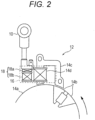
- FIG. 2 is a schematic view of an ignition device for the internal combustion engine 2 in the embodiment.
- the internal combustion engine 2 includes an ignition device 12 which operates the ignition plug 10.
- an ignition device 12 which operates the ignition plug 10.
- a flywheel 14a is mounted for associative operation.
- the ignition device 12 includes a pair of magnets 14b, an iron core 14c, and an input coil 14d.
- the pair of magnets 14b are provided on an outer periphery of the flywheel 14a.
- the iron core 14c has a U shape, and is arranged adjacent to the outer periphery of the flywheel 14a.
- the input coil 14d is wound around the iron core 14c.
- the ignition device 12 includes a control device 16, a primary coil 18a, and a secondary coil 18b.
- the control device 16 is connected to the input coil 14d.
- the primary coil 18a is connected to the control device 16.
- the secondary coil 18b is connected to the ignition plug 10.
- FIG. 3 is a circuit block diagram for illustrating a circuit configuration of the control device 16.
- the control device 16 includes a capacitor 24, a switching element 26, a signal input circuit 32, a microcomputer 20, a power supply circuit 30, a temperature sensor 50, and a temperature detection circuit 52.
- the above-mentioned primary coil 18a and secondary coil 18b are illustrated as an ignition coil 18.
- the voltage induced in the input coil 14d is supplied, as a power supply voltage, to the microcomputer 20 from an IN1 terminal of the microcomputer 20 via the power supply circuit 30.
- the power supply circuit 30 is formed of a rectifier circuit, a smoothing circuit, and the like (not shown). As a result, a stable power supply voltage is supplied to the microcomputer 20.
- the voltage induced in the input coil 14d is supplied, as a control signal, to the microcomputer 20 from an IN2 terminal of the microcomputer 20 via the signal input circuit 32.
- the signal input circuit 32 is formed of a waveform shaping circuit and the like (not shown).
- the control signal is supplied to the microcomputer 20.
- the control signal is a signal including one or more pulses per one rotation of the crankshaft.
- the control signal functions as a reference signal for generating an ignition control signal.
- the microcomputer 20 detects or calculates the number of rotations (rotation speed) and an angular position of the internal combustion engine 2 based on the control signal supplied via the signal input circuit 32.
- the microcomputer 20 generates the ignition control signal based on a detection result and a calculation result, and outputs the ignition control signal from an OUT1 terminal to the switching element 26.
- the switching element 26 is formed of, for example, thyristor.
- the switching element 26 is connected to the OUT1 terminal of the microcomputer 20.
- the switching element 26 is in a non-current-carrying state.
- the switching element 26 is in a current-carrying state.
- the capacitor 24 is charged by the voltage induced in the input coil 14d.
- the ignition control signal output from the microcomputer 20 is set to HIGH, to thereby bring the switching element 26 into the current-carrying state.
- the capacitor 24 is discharged, to thereby cause a current to flow through the primary coil 18a of the ignition coil 18.
- the current flowing through the primary coil 18a generates a high-voltage pulse in the secondary coil 18b of the ignition coil 18, to thereby operate the ignition plug 10.
- the temperature sensor 50 detects the temperature of the internal combustion engine 2, to thereby output a detection signal.
- the temperature sensor 50 is connected to the temperature detection circuit 52.
- the temperature detection circuit 52 supplies the detection signal to the microcomputer 20.
- the detection signal is digitized by the temperature detection circuit 52 or the microcomputer 20.
- the temperature detection circuit 52 is connected to an IN3 terminal of the microcomputer 20. With this configuration, the microcomputer 20 can acquire the temperature of the internal combustion engine 2.
- FIG. 4 is a flowchart for illustrating processing of control executed when the internal combustion engine 2 is to be started.
- the processing of FIG. 4 is executed by the microcomputer 20.
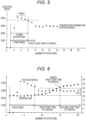
- FIG. 5 is a graph for showing an example of a relationship between a timing at which the rotation speed of the internal combustion engine 2 is checked and the rotation speed of the internal combustion engine 2 in a start mode of the internal combustion engine 2.
- FIG. 6 is a graph for showing an example of a condition under which first start-time PI control is canceled.
- FIG. 7 is a graph for showing an example of a condition under which second start-time PI control is canceled.
- the microcomputer 20 determines whether or not a PI control transition condition is satisfied (Step S411).
- the number of rotations at which the rotation speed of the internal combustion engine 2 is respectively equal to or higher than 3,800 RPM (transition determination rotation speed) within five rotations (first number of rotations) immediately after the internal combustion engine 2 starts (start mode) is equal to or larger than three rotations (second number of rotations), and hence it is determined that the PI control transition condition is satisfied.
- the control transitions to the first start-time PI control.
- the above-mentioned first number of rotations, second number of rotations, transition determination rotation speed, and the like are examples, and can appropriately be determined in accordance with the structure and characteristics of the internal combustion engine 2, for example.
- the transition determination rotation speed is a rotation speed lower than the clutch-in rotation speed. With this configuration, it is possible to transition to the first start-time PI control without occurrence of the clutch-in.
- the first start-time PI control is feedback control for stabilizing the rotation speed of the internal combustion engine 2 immediately after the engine starts. Specifically, the first start-time PI control controls the internal combustion engine 2 such that the rotation speed of the internal combustion engine 2 falls within a first rotation speed range including a target rotation speed. Through the feedback control as described above, it is possible to cause the rotation speed of the internal combustion engine 2 to quickly reach the target rotation speed and then maintain the target rotation speed.
- the proportional control and the integral control which are feedback control
- the PID control the proportional control, the integral control, and the differential control
- the first start-time PI control is only required to be a control, which causes the rotation speed of the internal combustion engine 2 to quickly reach the target rotation speed and then maintain the target rotation speed.
- the microcomputer 20 determines whether or not a finish condition for the first start-time PI control is satisfied.
- the finish condition for the first start-time PI control can be determined based on the temperature of the internal combustion engine 2, a deviation of the temperature of the internal combustion engine 2, and a time (number of rotations) in which the first start-time PI control is being executed. Based on those conditions, it is possible to determine whether or not the internal combustion engine 2 is stabilized immediately after the start. Another condition may be used as long as this condition can be used to determine the stability of the internal combustion engine 2.
- the microcomputer 20 determines whether or not the temperature of the internal combustion engine 2 is equal to or higher than a predetermined temperature (Step S415).
- the temperature of the internal combustion engine 2 can be detected by the above-mentioned temperature sensor 50.
- the microcomputer 20 determines whether or not the temperature deviation is equal to or larger than a predetermined value (Step S417).
- the temperature deviation can be calculated from a difference between the temperature exhibited when the first start-time PI control was started and the temperature detected by the temperature sensor 50 this time.
- the microcomputer 20 determines whether or not a timeout has occurred (whether or not a predetermined time has elapsed or whether or not a predetermined number of rotations has been exceeded) (Step S419).
- the microcomputer 20 When the timeout has not occurred (NO), the microcomputer 20 returns the process to Step S413, and continues the first start-time PI control.
- Step S415 When the temperature of the internal combustion engine 2 is equal to or higher than the predetermined temperature (YES) in the determination processing of Step S415, when the temperature deviation is equal to or larger than the predetermined value (YES) in the determination processing of Step S417, or when the timeout has occurred in the determination processing of Step S419, the microcomputer 20 determines that the finish condition for the first start-time PI control is satisfied, and hence executes the second start-time PI control (Step S421).
- the microcomputer 20 determines that the finish condition for the first start-time PI control is satisfied, and executes the second start-time PI control. Not only in the example of FIG. 6 , but also when the temperature of the internal combustion engine 2 has become equal to or higher than the predetermined temperature or when the predetermined time has elapsed as described above, the microcomputer 20 can determine that the finish condition for the first start-time PI control is satisfied, and can execute the second start-time PI control.
- the second start-time PI control is a control for preparing for acceleration after the rotation of the internal combustion engine 2 is stabilized through the first start-time PI control.
- the second start-time PI control is a control of making preparations so that the internal combustion engine 2 can quickly be accelerated in accordance with work of a user.
- the second start-time PI control controls the internal combustion engine 2 such that the rotation speed of the internal combustion engine 2 falls within a second rotation speed range wider than the first rotation speed range of the first start-time PI control. With this configuration, it is possible to increase an allowable range of the rotation speed of the internal combustion engine 2, to thereby adapt to a quick acceleration.
- the proportional control and the integral control which are the feedback control
- the PID control the proportional control, the integral control, and the differential control
- the second start-time PI control is only required to control the internal combustion engine 2 such that the rotation speed of the internal combustion engine 2 falls within the second rotation speed range.
- the microcomputer 20 determines whether or not a finish condition for the second start-time PI control is satisfied.
- the finish condition for the second start-time PI control can be determined in accordance with the rotation speed of the internal combustion engine 2 and an acceleration state of the internal combustion engine 2. Based on those conditions, it is possible to adapt the internal combustion engine 2 to a quick acceleration in accordance with the work of the user. Another condition may be used as long as the internal combustion engine 2 can adapt to a quick acceleration.
- the microcomputer 20 determines whether or not the rotation speed of the internal combustion engine 2 is equal to or higher than a predetermined rotation speed (Step S423).
- Step S425) When the rotation speed of the internal combustion engine 2 is lower than the predetermined rotation speed (NO), the microcomputer 20 determines whether or not the internal combustion engine 2 is accelerating (Step S425).
- Step S421 the microcomputer 20 returns the process to Step S421, and continues the second start-time PI control.
- Step S411 When the PI control transition condition is not satisfied (NO) in the determination processing of Step S411, when the rotation speed of the internal combustion engine 2 is equal to or higher than the predetermined rotation speed (YES) in the determination processing of Step S423, or when the internal combustion engine 2 is accelerating (YES) in the determination processing of Step S425, the microcomputer 20 transitions to normal ignition control (Step S427), and temporarily finishes this subroutine.
- the rotation speed of the internal combustion engine 2 has become equal to or higher than 8,000 RPM, and it is then determined that the finish condition for the second start-time PI control is satisfied.
- the microcomputer 20 transitions to the normal ignition control.
- the microcomputer 20 may determine that the finish condition for the second start-time PI control is satisfied, and may transition to the normal ignition control.
- FIG. 8(a) is a longitudinal sectional view for illustrating a structure of the carburetor 7 and is a transverse sectional view for illustrating the structure of the carburetor 7.
- the carburetor 7 in the embodiment is a carburetor of the rotary throttle valve type.
- the carburetor 7 includes an intake air flow rate control portion 70 and a fuel flow rate control portion 80.
- the intake air flow rate control portion 70 includes the rotatable rotary portion 72.
- the rotary portion 72 includes a passage 74 through which the air can pass.
- the passage 74 communicates with an air supply hole 76.
- the passage 74 communicates with the combustion chamber of the internal combustion engine 2. The air from an outside is supplied to the combustion chamber from the air supply hole 76 via the passage 74.
- the rotary portion 72 is rotated by an accelerator operation by the user.
- a direction of the passage 74 is changed in accordance with a rotation angle ⁇ of the rotary portion 72, to thereby change a degree of overlap between the air supply hole 76 and the passage 74.
- An air flow rate is controlled in accordance with the degree of overlap.
- the air flow rate of air to be supplied to the combustion chamber of the internal combustion engine 2 can be adjusted in accordance with the rotation angle ⁇ of the rotary portion 72.
- the rotary portion 72 functions as a throttle valve.
- the opening degree of the throttle valve have a target corresponding to a rotation speed equal to or higher than the clutch-in rotation speed and from 1.0 to 1.6 times the clutch-in rotation speed. With this configuration, good starting capability and good suppression controllability can be achieved. Moreover, it is more preferred that the opening degree of the throttle valve have a target corresponding to a rotation speed equal to or higher than the clutch-in rotation speed and from 1.0 to 1.3 times the clutch-in rotation speed. With this configuration, better starting capability and better suppression controllability can be achieved.
- the fuel flow rate control portion 80 includes a movable needle 82 and a fuel nozzle 84.
- the movable needle 82 can reciprocate in an up-and-down direction as the rotary portion 72 rotates.
- the movable needle 82 can operate in association with the rotary portion 72 through an operation association member 86.
- the operation association member 86 can be formed of, for example, a combination of cams having tapered surfaces or a combination of gears (not shown). The operation association member 86 is only required to convert a rotation motion of the rotary portion 72 to a linear motion of the movable needle 82.
- a tip of the movable needle 82 is movably inserted into the fuel nozzle 84.
- the fuel nozzle 84 supplies the fuel to the combustion chamber of the internal combustion engine 2.
- the air taken into the combustion chamber from the passage 74 and the fuel discharged from the fuel nozzle 84 are mixed into the air-fuel mixture, and the air-fuel mixture is supplied to the combustion chamber of the internal combustion engine 2.
- a depth of insertion into the fuel nozzle 84 is changed through the reciprocating motion of the movable needle 82.
- An amount of the fuel discharged from the fuel nozzle 84 can be adjusted based on the depth of insertion into the fuel nozzle 84, and hence a function as a fuel valve is implemented.
- the rotary portion 72 and the movable needle 82 operate in association with each other through the operation association member 86. Both the amount of the air taken into the combustion chamber from the passage 74 and the amount of the fuel discharged from the fuel nozzle 84 can simultaneously be adjusted through the operation association member 86, and hence an optimal air-fuel ratio can be set in accordance with the opening degree of the throttle valve.
- the operation association member 86 As the rotation angle ⁇ of the rotary portion 72 is reduced, the insertion depth of the movable needle 82 is reduced. Moreover, with the operation association member 86, as the rotation angle ⁇ of the rotary portion 72 is increased, the insertion depth of the movable needle 82 is increased. That is, it is possible to reduce the insertion depth of the movable needle 82, to thereby increase the amount of the fuel while the rotation angle ⁇ of the rotary portion 72 is reduced, to thereby increase the amount of the air (lift up). Moreover, it is possible to increase the insertion depth of the movable needle 82, to thereby decrease the amount of the fuel while the rotation angle ⁇ of the rotary portion 72 is increased, to thereby reduce the amount of the air.
- the starting capability and continuous stability after the start of the engine are improved by setting a target of the opening degree of the throttle value to an opening degree corresponding to a rotation speed equal to or lower than twice that of the clutch-in rotation speed, while the clutch-in rotation speed is considered as a reference.
- the engine rotation speed at the start is set to the rotation speed range higher than the clutch-in rotation speed, and hence it is possible to simplify a pattern of the fuel flow rate control in accordance with the air amount and the suppression control using the ignition device.
- a stable starting capability and the continuous stability after the start within a predetermined rotation speed range can be achieved by only building retardation control for an upper limit rotation speed slightly higher than the clutch-in rotation speed into the suppression control using the ignition device.
Landscapes
- Engineering & Computer Science (AREA)
- General Engineering & Computer Science (AREA)
- Mechanical Engineering (AREA)
- Chemical & Material Sciences (AREA)
- Combustion & Propulsion (AREA)
- Theoretical Computer Science (AREA)
- Signal Processing (AREA)
- Combined Controls Of Internal Combustion Engines (AREA)
Abstract
Description
- The present invention relates to an easy engine starting system capable of easily starting an engine.
- A related-art manual-recoil type working machine includes a lift-up member, and uses a mechanism of the lift-up member to determine both an amount of air and an amount of fuel to be supplied to an engine. In this manual-recoil type working machine, when the engine is to be started, the lift-up member is operated to increase a throttle opening degree to an opening degree corresponding to such output that clutch-in does not occur, to thereby start the engine.
[PTL 1]JP 10-131808 A - The related-art manual-recoil type working machine includes the lift-up member, and controls the amount of the air and the amount of the fuel within an output range in which the clutch-in does not occur. Thus, an effect is limited, and the start of the engine requires time in some cases.
- The present invention has been made in view of the above-mentioned problem, and has an object to provide an easy engine starting system capable of quickly and appropriately starting an engine even when the start of the engine is of a manual type such as a manual-recoil type working machine.
- A feature of an easy engine starting system according to one embodiment of the present invention resides in including: an engine; a centrifugal clutch configured to transmit a driving force of the engine to a driven device; and a control device configured to adjust output of the engine, and in that, when the engine is to be started, the engine is accelerated at start engine output which enables the engine to reach a rotation speed higher than a clutch-in rotation speed, and in that the control device has suppression control of suppressing, at the start engine output, the rotation speed to a rotation speed equal to or lower than the clutch-in rotation speed.
- According to the present invention, the engine can quickly and appropriately be started even when the start of the engine is of the manual type.
-
-
FIG. 1 is a schematic view of an engine in an embodiment of the present invention. -
FIG. 2 is a schematic view of an ignition device for the engine in the embodiment. -
FIG. 3 is a circuit block diagram of a control device (16). -
FIG. 4 is a flowchart for illustrating processing of control executed when an internal combustion engine (2) is started. -
FIG. 5 is a graph for showing an example of a relationship between a timing at which a rotation speed of the internal combustion engine (2) is checked and the number of rotations of the internal combustion engine (2) when the internal combustion engine (2) is to be started. -
FIG. 6 is a graph for showing an example of a condition under which first start-time PI control is canceled. -
FIG. 7 is a graph for showing an example of a condition under which second start-time PI control is canceled. -
FIG. 8(a) is a longitudinal sectional view for illustrating a structure of a carburetor (7), andFIG. 8(b) is a transverse sectional view for illustrating the structure of the carburetor (7) . - According to a first aspect, there is provided an easy engine starting system including: an engine; a centrifugal clutch configured to transmit a driving force of the engine to a driven device; and a control device configured to adjust output of the engine, wherein, when the engine is to be started, the engine is accelerated at start engine output which enables the engine to reach a rotation speed higher than a clutch-in rotation speed (the clutch-in rotation speed usually represents a rotation speed at which the clutch is started), and wherein the control device has suppression control of suppressing, at the start engine output, the rotation speed to a rotation speed equal to or lower than the clutch-in rotation speed.
- The easy engine starting system according to the first aspect includes the engine, the centrifugal clutch, and the control device.
- When the engine is to be started, the engine is accelerated at the start engine output which enables the engine to reach a rotation speed higher than the clutch-in rotation speed. For example, the engine is enabled to reach a rotation speed higher than the clutch-in rotation speed by controlling an amount of air and an amount of fuel supplied to the engine when the engine is to be started.
- It is only required for the engine to be able to reach the clutch-in rotation speed, and the engine does not actually reach the clutch-in rotation speed. Thus, the suppression control suppresses the rotation speed to a rotation speed equal to or lower than the clutch-in rotation speed.
- It is possible to simplify an operation for starting the engine (eliminate a choke operation, for example) by executing the control at the time when the engine is to be started through use of the start engine output and the suppression control, and even a user having a low skill can appropriately start the engine. Moreover, the engine can quickly be started, and can be brought into a usable state in a short time.
- According to a second aspect, in the first aspect, the easy engine starting system further includes a throttle valve configured to adjust an intake air amount supplied to a combustion chamber of the engine, and, at the start engine output, a throttle opening degree of the throttle valve is adjusted so as to enable the engine to reach a rotation speed higher than the clutch-in rotation speed.
- The amount of the air supplied to the combustion chamber of the engine is adjusted, and hence it is possible to enable the engine to appropriately reach a rotation speed higher than the clutch-in rotation speed.
- According to a third aspect, in the second aspect, the output of the engine is from 0.5 kW to 2 kW, and the throttle opening degree has a target corresponding to a rotation speed equal to or higher than the clutch-in rotation speed and equal to or lower than twice that of the clutch-in rotation speed.
- With this configuration, the rotation speed of the engine can quickly be increased.
- According to a fourth aspect, in the third aspect, the throttle opening degree has a target corresponding to a rotation speed equal to or higher than the clutch-in rotation speed and from 1.0 to 1.6 times the clutch-in rotation speed.
- With this configuration, good starting capability and good suppression controllability can be achieved.
- According to a fifth aspect, in the fourth aspect, the throttle opening degree has a target corresponding to a rotation speed equal to or higher than the clutch-in rotation speed and from 1.0 to 1.3 times the clutch-in rotation speed.
- With this configuration, better starting capability and better suppression controllability can be achieved.
- According to a sixth aspect, in the first to fifth aspects, the easy engine starting system further includes a detection unit configured to detect the rotation speed of the engine, and the suppression control is feedback control of determining an ignition timing from a deviation between a target rotation speed and the detected rotation speed.
- The rotation speed of the engine is detected, and the control is executed based on the difference from the target rotation speed. Thus, the rotation speed of the engine can quickly be stabilized while the rotation speed of the engine can quickly be increased.
- According to a seventh aspect, in the sixth aspect, the feedback control is started when at least one of the detected rotation speed, the rotation speed, or a time satisfies a predetermined condition after the engine is started.
- It is possible to allow the control to transition to the feedback control at an appropriate timing.
- According to an eighth aspect, in the sixth or seventh aspect, the feedback control has: first feedback control of executing feedback control such that the rotation speed falls within a first rotation speed range; and second feedback control of executing, after the first feedback control, feedback control such that the rotation speed falls within a second rotation speed range wider than the first rotation speed range.
- The rotation speed of the engine is stabilized through use of the first feedback control immediately after the engine start, and then the engine can be brought into a state in which the engine can be quickly accelerated through use of the second feedback control.
- According to a ninth aspect, in the first to eighth aspects, the engine includes a recoil having a rope to be pulled by hand when the engine is to be started.
- With this configuration, even a worker having relatively low physical strength can easily start the engine.
- According to a tenth aspect, in the ninth aspect, the easy engine starting system further includes a two-stroke engine mounted to a handheld blade working machine.
- With this configuration, the engine can easily be started, and the clutch-in does not occur. Thus, the engine can safely be started.
- The easy engine starting system further includes a fuel valve configured to adjust an amount of fuel supplied to the combustion chamber of the engine, and, together with the throttle opening degree, an opening degree of the fuel valve is adjusted.
- Not only the amount of the air, but also the amount of the fuel is adjusted, and hence the rotation speed of the engine can be controlled such that the rotation speed does not exceed the clutch-in rotation speed while the rotation speed is quickly increased.
- The easy engine starting system further includes an operation association mechanism configured to cause the throttle valve and the fuel valve to operate in association with each other.
- The control is executed through use of the operation association mechanism, and hence both the amount of the air and the amount of the fuel can easily be controlled.
- In the following, an embodiment of the present invention is described with reference to the drawings.
-
FIG. 1 is a schematic view of the engine in the embodiment. As illustrated inFIG. 1 , it is preferred that aninternal combustion engine 2 be a two-cycle gasoline engine. Theinternal combustion engine 2 includes acarburetor 7. Thecarburetor 7 includes a throttle valve (arotary portion 72 described later (seeFIG. 8 )) which adjusts an amount of air-fuel mixture caused to flow into theinternal combustion engine 2. The throttle valve is operated by a throttle lever or a choke knob (not shown), for example. As the throttle valve, a throttle valve which has hitherto been known can be used. - The
internal combustion engine 2 includes acylinder 2a, acrankshaft 2b, apiston 2c, and anignition plug 10. Thepiston 2c is arranged in thecylinder 2a, and is coupled to thecrankshaft 2b. The ignition plug 10 is arranged in a top portion of thecylinder 2a. - The
piston 2c moves up to a topdead center position 2d in the compression stroke of theinternal combustion engine 2. In general, theignition plug 10 is effectively operated at a timing before thepiston 2c reaches the topdead center position 2d, to thereby combust the air-fuel mixture in thecylinder 2a. A downward propelling force is applied to thepiston 2c through the combustion of the air-fuel mixture, to thereby generate a torque on thecrankshaft 2b. - The
internal combustion engine 2 can be mounted to a working machine or the like. The working machine can be, for example, a mowing robot of an autonomous type, a handheld working machine, or the like. - It is preferred that the
internal combustion engine 2 include a recoil having a rope to be pulled by hand when theinternal combustion engine 2 is to be started. With this configuration, even a person having relatively low physical strength can easily start theinternal combustion engine 2. Moreover, it is preferred that the easy engine starting system include a two-stroke engine mounted to a handheld blade working machine. With this configuration, the engine can easily be started, and the clutch-in does not occur. Thus, the engine can safely be started. - Output of the
internal combustion engine 2 refers to a workload of the engine. The output of theinternal combustion engine 2 is obtained by multiplying the torque by the rotation speed. Specifically, it is preferred that the output of theinternal combustion engine 2 be from 0.5 kW to 2 kW. When theinternal combustion engine 2 is used for a lawn mower equipped with a rotary carburetor, it is preferred that the output of theinternal combustion engine 2 be from 0.7 kW to 1.4 kW. -
FIG. 2 is a schematic view of an ignition device for theinternal combustion engine 2 in the embodiment. As illustrated inFIG. 2 , theinternal combustion engine 2 includes anignition device 12 which operates theignition plug 10. To the crankshaft (not shown) of theinternal combustion engine 2, aflywheel 14a is mounted for associative operation. Theignition device 12 includes a pair ofmagnets 14b, aniron core 14c, and aninput coil 14d. - The pair of
magnets 14b are provided on an outer periphery of theflywheel 14a. Theiron core 14c has a U shape, and is arranged adjacent to the outer periphery of theflywheel 14a. Theinput coil 14d is wound around theiron core 14c. - The
ignition device 12 includes acontrol device 16, aprimary coil 18a, and asecondary coil 18b. Thecontrol device 16 is connected to theinput coil 14d. Theprimary coil 18a is connected to thecontrol device 16. Thesecondary coil 18b is connected to theignition plug 10. -
FIG. 3 is a circuit block diagram for illustrating a circuit configuration of thecontrol device 16. As illustrated inFIG. 3 , thecontrol device 16 includes acapacitor 24, a switchingelement 26, asignal input circuit 32, amicrocomputer 20, apower supply circuit 30, atemperature sensor 50, and atemperature detection circuit 52. InFIG. 3 , the above-mentionedprimary coil 18a andsecondary coil 18b are illustrated as anignition coil 18. - When the
internal combustion engine 2 operates, the crankshaft rotates, and the pair ofmagnets 14b attached to theflywheel 14a pass through a vicinity of theiron core 14c having the U shape. As a result, a voltage is induced in theinput coil 14d, and is supplied to themicrocomputer 20. - The voltage induced in the
input coil 14d is supplied, as a power supply voltage, to themicrocomputer 20 from an IN1 terminal of themicrocomputer 20 via thepower supply circuit 30. Thepower supply circuit 30 is formed of a rectifier circuit, a smoothing circuit, and the like (not shown). As a result, a stable power supply voltage is supplied to themicrocomputer 20. - The voltage induced in the
input coil 14d is supplied, as a control signal, to themicrocomputer 20 from an IN2 terminal of themicrocomputer 20 via thesignal input circuit 32. Thesignal input circuit 32 is formed of a waveform shaping circuit and the like (not shown). As a result, the control signal is supplied to themicrocomputer 20. The control signal is a signal including one or more pulses per one rotation of the crankshaft. The control signal functions as a reference signal for generating an ignition control signal. - The
microcomputer 20 detects or calculates the number of rotations (rotation speed) and an angular position of theinternal combustion engine 2 based on the control signal supplied via thesignal input circuit 32. Themicrocomputer 20 generates the ignition control signal based on a detection result and a calculation result, and outputs the ignition control signal from an OUT1 terminal to the switchingelement 26. - The switching
element 26 is formed of, for example, thyristor. The switchingelement 26 is connected to the OUT1 terminal of themicrocomputer 20. When the ignition control signal output from the OUT1 terminal of themicrocomputer 20 is LOW, the switchingelement 26 is in a non-current-carrying state. When the ignition control signal output from the OUT1 terminal of themicrocomputer 20 is HIGH, the switchingelement 26 is in a current-carrying state. - When the ignition control signal output from the
microcomputer 20 is set to LOW, to thereby bring the switchingelement 26 into the non-current-carrying state, thecapacitor 24 is charged by the voltage induced in theinput coil 14d. When an ignition timing of theignition plug 10 is reached, the ignition control signal output from themicrocomputer 20 is set to HIGH, to thereby bring the switchingelement 26 into the current-carrying state. As a result, thecapacitor 24 is discharged, to thereby cause a current to flow through theprimary coil 18a of theignition coil 18. The current flowing through theprimary coil 18a generates a high-voltage pulse in thesecondary coil 18b of theignition coil 18, to thereby operate theignition plug 10. - The
temperature sensor 50 detects the temperature of theinternal combustion engine 2, to thereby output a detection signal. Thetemperature sensor 50 is connected to thetemperature detection circuit 52. Thetemperature detection circuit 52 supplies the detection signal to themicrocomputer 20. The detection signal is digitized by thetemperature detection circuit 52 or themicrocomputer 20. Thetemperature detection circuit 52 is connected to an IN3 terminal of themicrocomputer 20. With this configuration, themicrocomputer 20 can acquire the temperature of theinternal combustion engine 2. -
FIG. 4 is a flowchart for illustrating processing of control executed when theinternal combustion engine 2 is to be started. The processing ofFIG. 4 is executed by themicrocomputer 20.FIG. 5 is a graph for showing an example of a relationship between a timing at which the rotation speed of theinternal combustion engine 2 is checked and the rotation speed of theinternal combustion engine 2 in a start mode of theinternal combustion engine 2.FIG. 6 is a graph for showing an example of a condition under which first start-time PI control is canceled.FIG. 7 is a graph for showing an example of a condition under which second start-time PI control is canceled. - First, the
microcomputer 20 determines whether or not a PI control transition condition is satisfied (Step S411). - For example, when the number of rotations at which the rotation speed of the
internal combustion engine 2 is respectively higher than a transition determination rotation speed within a first number of rotations immediately after theinternal combustion engine 2 starts is equal to or higher than a second number of rotations, it is determined that the PI control transition condition is satisfied. - Specifically, as shown in
FIG. 5 , the number of rotations at which the rotation speed of theinternal combustion engine 2 is respectively equal to or higher than 3,800 RPM (transition determination rotation speed) within five rotations (first number of rotations) immediately after theinternal combustion engine 2 starts (start mode) is equal to or larger than three rotations (second number of rotations), and hence it is determined that the PI control transition condition is satisfied. As a result, the control transitions to the first start-time PI control. - The above-mentioned first number of rotations, second number of rotations, transition determination rotation speed, and the like are examples, and can appropriately be determined in accordance with the structure and characteristics of the
internal combustion engine 2, for example. The transition determination rotation speed is a rotation speed lower than the clutch-in rotation speed. With this configuration, it is possible to transition to the first start-time PI control without occurrence of the clutch-in. - After that, when the PI control transition condition is satisfied (YES), the
microcomputer 20 executes the first start-time PI control (Step S413). The first start-time PI control is feedback control for stabilizing the rotation speed of theinternal combustion engine 2 immediately after the engine starts. Specifically, the first start-time PI control controls theinternal combustion engine 2 such that the rotation speed of theinternal combustion engine 2 falls within a first rotation speed range including a target rotation speed. Through the feedback control as described above, it is possible to cause the rotation speed of theinternal combustion engine 2 to quickly reach the target rotation speed and then maintain the target rotation speed. - As the first start-time PI control, the proportional control and the integral control, which are feedback control, are used. However, the PID control (the proportional control, the integral control, and the differential control) may be used or other feedback control may be used. The first start-time PI control is only required to be a control, which causes the rotation speed of the
internal combustion engine 2 to quickly reach the target rotation speed and then maintain the target rotation speed. - After that, the
microcomputer 20 determines whether or not a finish condition for the first start-time PI control is satisfied. The finish condition for the first start-time PI control can be determined based on the temperature of theinternal combustion engine 2, a deviation of the temperature of theinternal combustion engine 2, and a time (number of rotations) in which the first start-time PI control is being executed. Based on those conditions, it is possible to determine whether or not theinternal combustion engine 2 is stabilized immediately after the start. Another condition may be used as long as this condition can be used to determine the stability of theinternal combustion engine 2. - Specifically, first, the
microcomputer 20 determines whether or not the temperature of theinternal combustion engine 2 is equal to or higher than a predetermined temperature (Step S415). The temperature of theinternal combustion engine 2 can be detected by the above-mentionedtemperature sensor 50. - When the temperature of the
internal combustion engine 2 is lower than the predetermined temperature (NO), that is, the temperature of theinternal combustion engine 2 is not sufficiently high, themicrocomputer 20 determines whether or not the temperature deviation is equal to or larger than a predetermined value (Step S417). The temperature deviation can be calculated from a difference between the temperature exhibited when the first start-time PI control was started and the temperature detected by thetemperature sensor 50 this time. - When the temperature deviation is within the predetermined value (NO), that is, a temperature change amount is not large, the
microcomputer 20 determines whether or not a timeout has occurred (whether or not a predetermined time has elapsed or whether or not a predetermined number of rotations has been exceeded) (Step S419). - When the timeout has not occurred (NO), the
microcomputer 20 returns the process to Step S413, and continues the first start-time PI control. - When the temperature of the
internal combustion engine 2 is equal to or higher than the predetermined temperature (YES) in the determination processing of Step S415, when the temperature deviation is equal to or larger than the predetermined value (YES) in the determination processing of Step S417, or when the timeout has occurred in the determination processing of Step S419, themicrocomputer 20 determines that the finish condition for the first start-time PI control is satisfied, and hence executes the second start-time PI control (Step S421). - For example, in the example of
FIG. 6 , when the temperature deviation has become equal to or larger than 10°C, themicrocomputer 20 determines that the finish condition for the first start-time PI control is satisfied, and executes the second start-time PI control. Not only in the example ofFIG. 6 , but also when the temperature of theinternal combustion engine 2 has become equal to or higher than the predetermined temperature or when the predetermined time has elapsed as described above, themicrocomputer 20 can determine that the finish condition for the first start-time PI control is satisfied, and can execute the second start-time PI control. - The second start-time PI control is a control for preparing for acceleration after the rotation of the
internal combustion engine 2 is stabilized through the first start-time PI control. Specifically, the second start-time PI control is a control of making preparations so that theinternal combustion engine 2 can quickly be accelerated in accordance with work of a user. The second start-time PI control controls theinternal combustion engine 2 such that the rotation speed of theinternal combustion engine 2 falls within a second rotation speed range wider than the first rotation speed range of the first start-time PI control. With this configuration, it is possible to increase an allowable range of the rotation speed of theinternal combustion engine 2, to thereby adapt to a quick acceleration. - As the second start-time PI control, the proportional control and the integral control, which are the feedback control, are used. However, the PID control (the proportional control, the integral control, and the differential control) may be used or other feedback control may be used. The second start-time PI control is only required to control the
internal combustion engine 2 such that the rotation speed of theinternal combustion engine 2 falls within the second rotation speed range. - After that, the
microcomputer 20 determines whether or not a finish condition for the second start-time PI control is satisfied. The finish condition for the second start-time PI control can be determined in accordance with the rotation speed of theinternal combustion engine 2 and an acceleration state of theinternal combustion engine 2. Based on those conditions, it is possible to adapt theinternal combustion engine 2 to a quick acceleration in accordance with the work of the user. Another condition may be used as long as theinternal combustion engine 2 can adapt to a quick acceleration. - Specifically, first, the
microcomputer 20 determines whether or not the rotation speed of theinternal combustion engine 2 is equal to or higher than a predetermined rotation speed (Step S423). - When the rotation speed of the
internal combustion engine 2 is lower than the predetermined rotation speed (NO), themicrocomputer 20 determines whether or not theinternal combustion engine 2 is accelerating (Step S425). - When the
internal combustion engine 2 is not accelerating (NO), themicrocomputer 20 returns the process to Step S421, and continues the second start-time PI control. - When the PI control transition condition is not satisfied (NO) in the determination processing of Step S411, when the rotation speed of the
internal combustion engine 2 is equal to or higher than the predetermined rotation speed (YES) in the determination processing of Step S423, or when theinternal combustion engine 2 is accelerating (YES) in the determination processing of Step S425, themicrocomputer 20 transitions to normal ignition control (Step S427), and temporarily finishes this subroutine. - For example, in the example shown in
FIG. 7 , the rotation speed of theinternal combustion engine 2 has become equal to or higher than 8,000 RPM, and it is then determined that the finish condition for the second start-time PI control is satisfied. As a result, themicrocomputer 20 transitions to the normal ignition control. Not only in the example ofFIG. 7 , but also when theinternal combustion engine 2 is brought into the acceleration state as described above, themicrocomputer 20 may determine that the finish condition for the second start-time PI control is satisfied, and may transition to the normal ignition control. -
FIG. 8(a) is a longitudinal sectional view for illustrating a structure of thecarburetor 7 and is a transverse sectional view for illustrating the structure of thecarburetor 7. Thecarburetor 7 in the embodiment is a carburetor of the rotary throttle valve type. - The
carburetor 7 includes an intake air flowrate control portion 70 and a fuel flowrate control portion 80. - The intake air flow
rate control portion 70 includes therotatable rotary portion 72. Therotary portion 72 includes apassage 74 through which the air can pass. Thepassage 74 communicates with anair supply hole 76. Thepassage 74 communicates with the combustion chamber of theinternal combustion engine 2. The air from an outside is supplied to the combustion chamber from theair supply hole 76 via thepassage 74. - The
rotary portion 72 is rotated by an accelerator operation by the user. A direction of thepassage 74 is changed in accordance with a rotation angle θ of therotary portion 72, to thereby change a degree of overlap between theair supply hole 76 and thepassage 74. An air flow rate is controlled in accordance with the degree of overlap. As described above, the air flow rate of air to be supplied to the combustion chamber of theinternal combustion engine 2 can be adjusted in accordance with the rotation angle θ of therotary portion 72. Therotary portion 72 functions as a throttle valve. - It is preferred that the opening degree of the throttle valve have a target corresponding to a rotation speed equal to or higher than the clutch-in rotation speed and from 1.0 to 1.6 times the clutch-in rotation speed. With this configuration, good starting capability and good suppression controllability can be achieved. Moreover, it is more preferred that the opening degree of the throttle valve have a target corresponding to a rotation speed equal to or higher than the clutch-in rotation speed and from 1.0 to 1.3 times the clutch-in rotation speed. With this configuration, better starting capability and better suppression controllability can be achieved.
- The fuel flow
rate control portion 80 includes amovable needle 82 and afuel nozzle 84. Themovable needle 82 can reciprocate in an up-and-down direction as therotary portion 72 rotates. Themovable needle 82 can operate in association with therotary portion 72 through anoperation association member 86. Theoperation association member 86 can be formed of, for example, a combination of cams having tapered surfaces or a combination of gears (not shown). Theoperation association member 86 is only required to convert a rotation motion of therotary portion 72 to a linear motion of themovable needle 82. - A tip of the
movable needle 82 is movably inserted into thefuel nozzle 84. Thefuel nozzle 84 supplies the fuel to the combustion chamber of theinternal combustion engine 2. The air taken into the combustion chamber from thepassage 74 and the fuel discharged from thefuel nozzle 84 are mixed into the air-fuel mixture, and the air-fuel mixture is supplied to the combustion chamber of theinternal combustion engine 2. - A depth of insertion into the
fuel nozzle 84 is changed through the reciprocating motion of themovable needle 82. An amount of the fuel discharged from thefuel nozzle 84 can be adjusted based on the depth of insertion into thefuel nozzle 84, and hence a function as a fuel valve is implemented. - As described above, the
rotary portion 72 and themovable needle 82 operate in association with each other through theoperation association member 86. Both the amount of the air taken into the combustion chamber from thepassage 74 and the amount of the fuel discharged from thefuel nozzle 84 can simultaneously be adjusted through theoperation association member 86, and hence an optimal air-fuel ratio can be set in accordance with the opening degree of the throttle valve. - Specifically, with the
operation association member 86, as the rotation angle θ of therotary portion 72 is reduced, the insertion depth of themovable needle 82 is reduced. Moreover, with theoperation association member 86, as the rotation angle θ of therotary portion 72 is increased, the insertion depth of themovable needle 82 is increased. That is, it is possible to reduce the insertion depth of themovable needle 82, to thereby increase the amount of the fuel while the rotation angle θ of therotary portion 72 is reduced, to thereby increase the amount of the air (lift up). Moreover, it is possible to increase the insertion depth of themovable needle 82, to thereby decrease the amount of the fuel while the rotation angle θ of therotary portion 72 is increased, to thereby reduce the amount of the air. - As described above, in the configuration which associates the opening degree of the throttle valve and the fuel flow rate control with each other, the starting capability and continuous stability after the start of the engine are improved by setting a target of the opening degree of the throttle value to an opening degree corresponding to a rotation speed equal to or lower than twice that of the clutch-in rotation speed, while the clutch-in rotation speed is considered as a reference. In particular, it is preferred to set the target of the opening degree of the throttle valve to the opening degree corresponding to 1.0 to 1.6 times the clutch-in rotation speed. In this configuration, the engine rotation speed at the start is set to the rotation speed range higher than the clutch-in rotation speed, and hence it is possible to simplify a pattern of the fuel flow rate control in accordance with the air amount and the suppression control using the ignition device. For example, a stable starting capability and the continuous stability after the start within a predetermined rotation speed range can be achieved by only building retardation control for an upper limit rotation speed slightly higher than the clutch-in rotation speed into the suppression control using the ignition device.
- Further, it is preferred to provide such a configuration of setting the target of the opening degree of the throttle valve to an opening degree corresponding to 1.0 to 1.3 times the clutch-in rotation speed. With this configuration, in addition to the above-mentioned starting capability and simplified suppression control, the control of the fuel flow rate, that is, the control of the movement amount of the
movable needle 82 can be minimized, and hence an increase in complexity of a carburetor main body and peripheral components can be avoided while the quick and reliable starting capability and the continuous stability after the start are maintained. Such a configuration is preferred for a portable working machine having output of engine of from 0.5 kW to 2 kW. - As described above, the embodiment of the present invention has been described, but it should not be understood that the description and the drawings that form a part of this disclosure limit this disclosure. This disclosure includes various embodiments and others which are not described herein.
Claims (10)
- An easy engine starting system, comprising:an engine;a centrifugal clutch configured to transmit a driving force of the engine to a driven device; anda control device configured to adjust output of the engine,wherein, when the engine is to be started, the engine is accelerated at start engine output which enables the engine to reach a rotation speed higher than a clutch-in rotation speed, andwherein the control device has suppression control of suppressing, at the start engine output, the rotation speed to a rotation speed equal to or lower than the clutch-in rotation speed.
- The easy engine starting system according to claim 1, further comprising a throttle valve configured to adjust an intake air amount supplied to a combustion chamber of the engine,
wherein, at the start engine output, a throttle opening degree of the throttle valve is adjusted so as to enable the engine to reach a rotation speed higher than the clutch-in rotation speed. - The easy engine starting system according to claim 2, wherein the output of the engine is from 0.5 kW to 2 kW, and the throttle opening degree has a target corresponding to a rotation speed equal to or higher than the clutch-in rotation speed and equal to or lower than twice that of the clutch-in rotation speed.
- The easy engine starting system according to claim 3, wherein the throttle opening degree has a target corresponding to a rotation speed equal to or higher than the clutch-in rotation speed and from 1.0 to 1.6 times the clutch-in rotation speed.
- The easy engine starting system according to claim 4, wherein the throttle opening degree has a target corresponding to a rotation speed equal to or higher than the clutch-in rotation speed and from 1.0 to 1.3 times the clutch-in rotation speed.
- The easy engine starting system according to any one of claims 1 to 5, further comprising a detection unit configured to detect the rotation speed of the engine,
wherein the suppression control is feedback control of determining an ignition timing from a deviation between a target rotation speed and the detected rotation speed. - The easy engine starting system according to claim 6, wherein the feedback control is started when at least one of the detected rotation speed, the rotation speed, or a time satisfies a predetermined condition after the engine is started.
- The easy engine starting system according to claim 6 or 7, wherein the feedback control has:first feedback control of executing feedback control such that the rotation speed falls within a first rotation speed range; andsecond feedback control of executing, after the first feedback control, feedback control such that the rotation speed falls within a second rotation speed range wider than the first rotation speed range.
- The easy engine starting system according to any one of claims 1 to 8, wherein the engine includes a recoil having a rope to be pulled by hand when the engine is to be started.
- The easy engine starting system according to claim 9, further comprising a two-stroke engine mounted to a handheld blade working machine.
Applications Claiming Priority (1)
| Application Number | Priority Date | Filing Date | Title |
|---|---|---|---|
| PCT/JP2021/016648 WO2022230023A1 (en) | 2021-04-26 | 2021-04-26 | Easy engine starting system |
Publications (3)
| Publication Number | Publication Date |
|---|---|
| EP4332369A1 true EP4332369A1 (en) | 2024-03-06 |
| EP4332369A4 EP4332369A4 (en) | 2025-03-05 |
| EP4332369B1 EP4332369B1 (en) | 2025-12-31 |
Family
ID=83846799
Family Applications (1)
| Application Number | Title | Priority Date | Filing Date |
|---|---|---|---|
| EP21939186.9A Active EP4332369B1 (en) | 2021-04-26 | 2021-04-26 | ENGINE START SYSTEM |
Country Status (4)
| Country | Link |
|---|---|
| US (1) | US12577929B2 (en) |
| EP (1) | EP4332369B1 (en) |
| JP (1) | JP7738649B2 (en) |
| WO (1) | WO2022230023A1 (en) |
Family Cites Families (17)
| Publication number | Priority date | Publication date | Assignee | Title |
|---|---|---|---|---|
| JPH041342Y2 (en) * | 1984-09-05 | 1992-01-17 | ||
| JPH10131808A (en) | 1996-10-29 | 1998-05-19 | Zama Japan Kk | Carburetter of rotary throttle valve type |
| JP2007046495A (en) * | 2005-08-08 | 2007-02-22 | Honda Motor Co Ltd | Engine speed control device for work equipment |
| DE102012015034A1 (en) * | 2012-07-31 | 2014-02-27 | Andreas Stihl Ag & Co. Kg | Method for switching off a speed limitation in an internal combustion engine |
| CN104781525A (en) * | 2012-11-14 | 2015-07-15 | 日立工机株式会社 | Engine working machine |
| DE102013005807A1 (en) * | 2013-04-04 | 2014-10-09 | Andreas Stihl Ag & Co. Kg | Method for operating an internal combustion engine |
| DE102013009669B4 (en) | 2013-06-08 | 2022-01-05 | Andreas Stihl Ag & Co. Kg | Internal combustion engine with a starting device |
| DE102013021832A1 (en) * | 2013-12-21 | 2015-06-25 | Andreas Stihl Ag & Co. Kg | Method for operating a hand-held implement with an internal combustion engine |
| JP6233018B2 (en) * | 2013-12-27 | 2017-11-22 | 日立工機株式会社 | Engine working machine |
| JP2016079843A (en) | 2014-10-14 | 2016-05-16 | 株式会社やまびこ | Engine-driven work machine |
| JP6424956B2 (en) * | 2015-04-28 | 2018-11-21 | 工機ホールディングス株式会社 | Chain saw |
| JP2018091353A (en) | 2016-11-30 | 2018-06-14 | 日立工機株式会社 | Engine working machine |
| JP2018091235A (en) | 2016-12-02 | 2018-06-14 | 株式会社やまびこ | Portable engine working machine and rotary carburetor incorporated therein |
| JP2018204496A (en) | 2017-06-01 | 2018-12-27 | 株式会社やまびこ | Engine working machine |
| DE102018002964A1 (en) * | 2017-09-15 | 2019-03-21 | Andreas Stihl Ag & Co. Kg | Hand-held implement |
| JP7158936B2 (en) | 2018-07-20 | 2022-10-24 | 株式会社やまびこ | portable engine work machine |
| EP3604778B1 (en) * | 2018-08-03 | 2021-04-07 | Andreas Stihl AG & Co. KG | Method for starting an internal combustion engine |
-
2021
- 2021-04-26 EP EP21939186.9A patent/EP4332369B1/en active Active
- 2021-04-26 WO PCT/JP2021/016648 patent/WO2022230023A1/en not_active Ceased
- 2021-04-26 US US18/554,632 patent/US12577929B2/en active Active
- 2021-04-26 JP JP2023516878A patent/JP7738649B2/en active Active
Also Published As
| Publication number | Publication date |
|---|---|
| JP7738649B2 (en) | 2025-09-12 |
| WO2022230023A1 (en) | 2022-11-03 |
| JPWO2022230023A1 (en) | 2022-11-03 |
| EP4332369B1 (en) | 2025-12-31 |
| EP4332369A4 (en) | 2025-03-05 |
| US12577929B2 (en) | 2026-03-17 |
| US20240044309A1 (en) | 2024-02-08 |
Similar Documents
| Publication | Publication Date | Title |
|---|---|---|
| JP5264328B2 (en) | Two-cycle engine operation method | |
| US6076503A (en) | Electronically controlled carburetor | |
| US7246591B2 (en) | Automatic choke control system for general-purpose engine | |
| SE459601B (en) | TIME ADJUSTMENT OF BRAIN SPRAY INJECTING A TWO-TASK ENGINE PROVIDED BY DIRECT INJECTION | |
| EP2787194B1 (en) | Internal combustion engine | |
| EP4332369B1 (en) | ENGINE START SYSTEM | |
| US11199141B2 (en) | Generator driven by engine | |
| KR20150060973A (en) | Diesel engine control device, diesel engine, and diesel engine control method | |
| JP7158936B2 (en) | portable engine work machine | |
| CN102278208A (en) | Small engine and engine operating machine having the small engine | |
| EP3237739B1 (en) | Internal combustion engine and method for safe starting the same | |
| EP2670956B1 (en) | 2-cycle engine and engine-powered working machine having the same | |
| EP3491232B1 (en) | Method for controlling the operation of a two-stroke spark ignition internal combustion engine | |
| WO2014002951A1 (en) | Power device, and portable working machine provided therewith | |
| JP5369070B2 (en) | Fuel outage judgment device for general-purpose engines | |
| JP5691500B2 (en) | Small engine and engine working machine equipped with the same | |
| JPS61232339A (en) | Controller of internal-combustion engine for working machine | |
| JPH09112350A (en) | Engine fuel supply control system and air bleed control device thereof | |
| JP2022103808A (en) | Engine and work mounted with engine | |
| JPH0730918Y2 (en) | Internal combustion engine carburetor | |
| RU104638U1 (en) | IGNITION ANGLE CONTROL DEVICE | |
| JP2020084794A (en) | Portable engine work machine | |
| JP2012057534A (en) | Control device for general-purpose engine | |
| JP4594348B2 (en) | Crank chamber pre-compression type 2-cycle gasoline engine controller | |
| JPS631456B2 (en) |
Legal Events
| Date | Code | Title | Description |
|---|---|---|---|
| STAA | Information on the status of an ep patent application or granted ep patent |
Free format text: STATUS: THE INTERNATIONAL PUBLICATION HAS BEEN MADE |
|
| PUAI | Public reference made under article 153(3) epc to a published international application that has entered the european phase |
Free format text: ORIGINAL CODE: 0009012 |
|
| STAA | Information on the status of an ep patent application or granted ep patent |
Free format text: STATUS: REQUEST FOR EXAMINATION WAS MADE |
|
| 17P | Request for examination filed |
Effective date: 20231005 |
|
| AK | Designated contracting states |
Kind code of ref document: A1 Designated state(s): AL AT BE BG CH CY CZ DE DK EE ES FI FR GB GR HR HU IE IS IT LI LT LU LV MC MK MT NL NO PL PT RO RS SE SI SK SM TR |
|
| DAV | Request for validation of the european patent (deleted) | ||
| DAX | Request for extension of the european patent (deleted) | ||
| REG | Reference to a national code |
Ref country code: DE Ref legal event code: R079 Free format text: PREVIOUS MAIN CLASS: F02N0003020000 Ipc: F02N0015020000 Ref country code: DE Ref legal event code: R079 Ref document number: 602021045809 Country of ref document: DE Free format text: PREVIOUS MAIN CLASS: F02N0003020000 Ipc: F02N0015020000 |
|
| A4 | Supplementary search report drawn up and despatched |
Effective date: 20250130 |
|
| RIC1 | Information provided on ipc code assigned before grant |
Ipc: F02N 3/02 20060101ALN20250124BHEP Ipc: F02M 9/06 20060101ALI20250124BHEP Ipc: F02M 7/18 20060101ALI20250124BHEP Ipc: F02D 41/06 20060101ALI20250124BHEP Ipc: F02D 41/02 20060101ALI20250124BHEP Ipc: F02B 63/02 20060101ALI20250124BHEP Ipc: F02P 5/15 20060101ALI20250124BHEP Ipc: F02P 1/08 20060101ALI20250124BHEP Ipc: F02N 15/02 20060101AFI20250124BHEP |
|
| GRAP | Despatch of communication of intention to grant a patent |
Free format text: ORIGINAL CODE: EPIDOSNIGR1 |
|
| STAA | Information on the status of an ep patent application or granted ep patent |
Free format text: STATUS: GRANT OF PATENT IS INTENDED |
|
| RIC1 | Information provided on ipc code assigned before grant |
Ipc: F02N 15/02 20060101AFI20250709BHEP Ipc: F02P 1/08 20060101ALI20250709BHEP Ipc: F02P 5/15 20060101ALI20250709BHEP Ipc: F02B 63/02 20060101ALI20250709BHEP Ipc: F02D 41/02 20060101ALI20250709BHEP Ipc: F02D 41/06 20060101ALI20250709BHEP Ipc: F02M 7/18 20060101ALI20250709BHEP Ipc: F02M 9/06 20060101ALI20250709BHEP Ipc: F02N 3/02 20060101ALN20250709BHEP |
|
| INTG | Intention to grant announced |
Effective date: 20250801 |
|
| GRAS | Grant fee paid |
Free format text: ORIGINAL CODE: EPIDOSNIGR3 |
|
| GRAA | (expected) grant |
Free format text: ORIGINAL CODE: 0009210 |
|
| STAA | Information on the status of an ep patent application or granted ep patent |
Free format text: STATUS: THE PATENT HAS BEEN GRANTED |
|
| AK | Designated contracting states |
Kind code of ref document: B1 Designated state(s): AL AT BE BG CH CY CZ DE DK EE ES FI FR GB GR HR HU IE IS IT LI LT LU LV MC MK MT NL NO PL PT RO RS SE SI SK SM TR |
|
| REG | Reference to a national code |
Ref country code: CH Ref legal event code: F10 Free format text: ST27 STATUS EVENT CODE: U-0-0-F10-F00 (AS PROVIDED BY THE NATIONAL OFFICE) Effective date: 20251231 Ref country code: GB Ref legal event code: FG4D |
|
| REG | Reference to a national code |
Ref country code: DE Ref legal event code: R096 Ref document number: 602021045809 Country of ref document: DE |
|
| REG | Reference to a national code |
Ref country code: IE Ref legal event code: FG4D |
|
| PGFP | Annual fee paid to national office [announced via postgrant information from national office to epo] |
Ref country code: GB Payment date: 20260321 Year of fee payment: 6 |
|
| REG | Reference to a national code |
Ref country code: LT Ref legal event code: MG9D |
|
| PG25 | Lapsed in a contracting state [announced via postgrant information from national office to epo] |
Ref country code: NO Free format text: LAPSE BECAUSE OF FAILURE TO SUBMIT A TRANSLATION OF THE DESCRIPTION OR TO PAY THE FEE WITHIN THE PRESCRIBED TIME-LIMIT Effective date: 20260331 |
|
| PG25 | Lapsed in a contracting state [announced via postgrant information from national office to epo] |
Ref country code: HR Free format text: LAPSE BECAUSE OF FAILURE TO SUBMIT A TRANSLATION OF THE DESCRIPTION OR TO PAY THE FEE WITHIN THE PRESCRIBED TIME-LIMIT Effective date: 20251231 Ref country code: FI Free format text: LAPSE BECAUSE OF FAILURE TO SUBMIT A TRANSLATION OF THE DESCRIPTION OR TO PAY THE FEE WITHIN THE PRESCRIBED TIME-LIMIT Effective date: 20251231 |
|
| PG25 | Lapsed in a contracting state [announced via postgrant information from national office to epo] |
Ref country code: RS Free format text: LAPSE BECAUSE OF FAILURE TO SUBMIT A TRANSLATION OF THE DESCRIPTION OR TO PAY THE FEE WITHIN THE PRESCRIBED TIME-LIMIT Effective date: 20260331 |
|
| PG25 | Lapsed in a contracting state [announced via postgrant information from national office to epo] |
Ref country code: LV Free format text: LAPSE BECAUSE OF FAILURE TO SUBMIT A TRANSLATION OF THE DESCRIPTION OR TO PAY THE FEE WITHIN THE PRESCRIBED TIME-LIMIT Effective date: 20251231 |