EP4332349A1 - Simultaneously assembling rotor blades with a gas turbine engine rotor disk - Google Patents
Simultaneously assembling rotor blades with a gas turbine engine rotor disk Download PDFInfo
- Publication number
- EP4332349A1 EP4332349A1 EP23192217.0A EP23192217A EP4332349A1 EP 4332349 A1 EP4332349 A1 EP 4332349A1 EP 23192217 A EP23192217 A EP 23192217A EP 4332349 A1 EP4332349 A1 EP 4332349A1
- Authority
- EP
- European Patent Office
- Prior art keywords
- rotor
- support structure
- disk
- rotor blades
- attachments
- Prior art date
- Legal status (The legal status is an assumption and is not a legal conclusion. Google has not performed a legal analysis and makes no representation as to the accuracy of the status listed.)
- Pending
Links
- 238000000034 method Methods 0.000 claims abstract description 34
- 230000000284 resting effect Effects 0.000 claims description 9
- 230000005484 gravity Effects 0.000 claims description 7
- 238000011144 upstream manufacturing Methods 0.000 description 4
- 238000002485 combustion reaction Methods 0.000 description 3
- 241000218642 Abies Species 0.000 description 2
- 230000004323 axial length Effects 0.000 description 2
- 238000010586 diagram Methods 0.000 description 2
- 210000003746 feather Anatomy 0.000 description 2
- 239000000446 fuel Substances 0.000 description 2
- 239000000203 mixture Substances 0.000 description 2
- 230000006835 compression Effects 0.000 description 1
- 238000007906 compression Methods 0.000 description 1
- 238000009434 installation Methods 0.000 description 1
- 238000007789 sealing Methods 0.000 description 1
- 125000006850 spacer group Chemical group 0.000 description 1
Images


Classifications
-
- F—MECHANICAL ENGINEERING; LIGHTING; HEATING; WEAPONS; BLASTING
- F01—MACHINES OR ENGINES IN GENERAL; ENGINE PLANTS IN GENERAL; STEAM ENGINES
- F01D—NON-POSITIVE DISPLACEMENT MACHINES OR ENGINES, e.g. STEAM TURBINES
- F01D25/00—Component parts, details, or accessories, not provided for in, or of interest apart from, other groups
- F01D25/28—Supporting or mounting arrangements, e.g. for turbine casing
- F01D25/285—Temporary support structures, e.g. for testing, assembling, installing, repairing; Assembly methods using such structures
-
- F—MECHANICAL ENGINEERING; LIGHTING; HEATING; WEAPONS; BLASTING
- F01—MACHINES OR ENGINES IN GENERAL; ENGINE PLANTS IN GENERAL; STEAM ENGINES
- F01D—NON-POSITIVE DISPLACEMENT MACHINES OR ENGINES, e.g. STEAM TURBINES
- F01D5/00—Blades; Blade-carrying members; Heating, heat-insulating, cooling or antivibration means on the blades or the members
- F01D5/30—Fixing blades to rotors; Blade roots ; Blade spacers
- F01D5/3007—Fixing blades to rotors; Blade roots ; Blade spacers of axial insertion type
-
- F—MECHANICAL ENGINEERING; LIGHTING; HEATING; WEAPONS; BLASTING
- F01—MACHINES OR ENGINES IN GENERAL; ENGINE PLANTS IN GENERAL; STEAM ENGINES
- F01D—NON-POSITIVE DISPLACEMENT MACHINES OR ENGINES, e.g. STEAM TURBINES
- F01D11/00—Preventing or minimising internal leakage of working-fluid, e.g. between stages
- F01D11/005—Sealing means between non relatively rotating elements
- F01D11/006—Sealing the gap between rotor blades or blades and rotor
-
- F—MECHANICAL ENGINEERING; LIGHTING; HEATING; WEAPONS; BLASTING
- F05—INDEXING SCHEMES RELATING TO ENGINES OR PUMPS IN VARIOUS SUBCLASSES OF CLASSES F01-F04
- F05D—INDEXING SCHEME FOR ASPECTS RELATING TO NON-POSITIVE-DISPLACEMENT MACHINES OR ENGINES, GAS-TURBINES OR JET-PROPULSION PLANTS
- F05D2230/00—Manufacture
- F05D2230/60—Assembly methods
- F05D2230/68—Assembly methods using auxiliary equipment for lifting or holding
Definitions
- This disclosure (invention) relates generally to a gas turbine engine and, more particularly, to methods and tools for assembling a bladed rotor for the gas turbine engine.
- a gas turbine engine includes multiple bladed rotors such as, but not limited to, a fan rotor, a compressor rotor and a turbine rotor.
- Each bladed rotor may include a rotor disk and a plurality of rotor blades mechanically attached to the rotor disk.
- the bladed rotor may also include feather seals for sealing inter-platform gaps between circumferentially neighboring rotor blades.
- Various methods and tools are known in the art for assembling a bladed rotor. While these known assembly methods and tools have various advantages, there is still room in the art for improvement.
- a method for assembling a rotor of a gas turbine engine.
- a rotor disk is provided that includes an axis and a plurality of slots arranged circumferentially about the axis in an array.
- a plurality of rotor blades are provided that include a plurality of airfoils and a plurality of attachments. Each of the rotor blades includes a respective one of the airfoils and a respective one of the attachments.
- Each of the attachments is inserted partially into a respective one of the slots.
- the rotor blades are rested on top of a blade support structure.
- the blade support structure is lowered axially downward along the rotor disk to simultaneously seat the attachments into the slots.
- a rotor disk a plurality of rotor blades and a plurality of seal elements are provided.
- the rotor disk includes an axis and a plurality of slots arranged circumferentially about the axis in an array.
- the rotor blades include a plurality of airfoils and a plurality of attachments. Each of the rotor blades includes a respective one of the airfoils and a respective one of the attachments.
- Each of the attachments is inserted partially into a respective one of the slots.
- Each of the seal elements is arranged between a respective circumferentially neighboring pair of the rotor blades.
- the attachments are simultaneously seated into the slots using a force of gravity alone to push the attachments into the slots.
- a fixture for assembling a rotor of a gas turbine engine.
- This assembly fixture includes a disk support structure and a blade support structure.
- the disk support structure is configured to support a rotor disk of the rotor during assembly of the rotor.
- the disk support structure includes a base, a radial locator and an axial locator circumscribing the radial locator.
- the radial locator projects axially along an axis out from a first side of the base.
- the radial locator is configured to radially locate and engage the rotor disk on the disk support structure.
- the axial locator projects axially along the axis out from the first side of the base.
- the axial locator is configured to axially locate and engage the rotor disk on the disk support structure.
- the blade support structure is configured to support a plurality of rotor blades of the rotor during the assembly of the rotor.
- the blade support structure circumscribes and is slidable against an outer periphery of the disk support structure.
- the blade support structure extends axially along the axis to a planar annular surface configured to axially locate and engage the rotor blades while attachments of the rotor blades are seated in slots in the rotor disk.
- the assembly fixture may also include a guide connected to the disk support structure and projecting radially into a slot in the blade support structure.
- the slot may extend within the blade support structure along a longitudinal trajectory.
- a first section of the longitudinal trajectory may have an axial component and a circumferential component.
- a second section of the longitudinal trajectory may have a circumferential component.
- the assembly fixture may also include a lock configured to rotatably fix the blade support structure to the disk support structure.
- the rotor blades may also include a plurality of platforms. Each of the rotor blades may also include a respective one of the platforms. Axial edges of the platforms may define a reference plane while the attachments are seated into the slots.
- the method may also include resting the axial edges of the platforms on top of a planar annular surface of a blade support structure as the attachments are seated into the slots.
- Gravity may maintain the rotor blades resting on top of the blade support structure as the blade support structure is lowered axially downward along the rotor disk.
- the method may also include: providing a plurality of seal elements; and inserting each of the seal elements into a respective cavity formed by and between a respective circumferentially neighboring pair of the rotor blades.
- Each of the seal elements may be inserted into the respective cavity prior to the lowering of the blade support structure.
- Each of the seal elements may be inserted into the respective cavity subsequent to the inserting of each of the attachments partially into the respective one of the slots.
- the seal elements may include a first seal element.
- the first seal element may include a base and a plurality of tabs connected to and projecting out from the base.
- Each of the tabs may project radially inward from the base to a distal tab end.
- the rotor disk may also include a plurality of lugs.
- Each of the slots may be formed by and between a respective circumferentially neighboring pair of the lugs.
- a first of the lugs may project radially outward to a distal lug end including a first end surface and a second end surface recessed radially inward from the first end surface.
- a first of the tabs may be operable to radially engage the first end surface and a second of the tabs may be operable to radially engage the second end surface.
- the rotor blades may be rested on a planar annular surface of the blade support structure.
- the rotor blades may also include a plurality of platforms. Each of the rotor blades may include a respective one of the platforms. The resting of the rotor blades may include resting axial edges of the platforms on top of the planar annular surface.
- the method may also include rotating the blade support structure about the axis while the blade support structure is lowered axially downward along the rotor disk.
- the method may also include disposing the rotor disk on top of a disk support structure.
- the blade support structure may be mated with and circumscribe the disk support structure.
- the method may also include lifting the rotor off of an assembly fixture.
- the rotor may include the rotor disk and the rotor blades.
- the assembly fixture may include the blade support structure.
- the rotor disk may include a turbine disk of the gas turbine engine.
- the rotor blades may include a plurality of turbine blades of the gas turbine engine.
- the invention may include any one or more of the individual features disclosed above and/or below alone or in any combination thereof.
- FIG. 1 schematically illustrates a bladed rotor 20 for a gas turbine engine.
- This bladed rotor 20 is rotatable about a rotational axis 22, which rotational axis 22 is also an axial centerline of the bladed rotor 20.
- the bladed rotor 20 of FIG. 1 includes a rotor disk 24 and a plurality of rotor blades 26 attached to and arranged circumferentially around the rotor disk 24 in a circular array.
- the bladed rotor 20 of FIG. 1 also includes a plurality of seal elements 28; e.g., feather seals.
- the rotor disk 24 extends radially between and to a radial inner side 30 of the rotor disk 24 and a radial outer side 32 of the rotor disk 24.
- the rotor disk 24 extends axially along the axis 22 between and to an axial first (e.g., upstream) side 34 of the rotor disk 24 and an axial second (e.g., downstream) side 36 of the rotor disk 24.
- the rotor disk 24 extends circumferentially around the axis 22 providing the rotor disk 24 with an annular body.
- the rotor disk 24 includes a disk hub 38, a disk web 40 and a disk rim 42.
- the disk hub 38 is disposed at the disk inner side 30.
- the disk hub 38 forms a bore 44 through the rotor disk 24 along the axis 22 between the disk first side 34 and the disk second side 36; see also FIG. 2 .
- the disk web 40 is disposed radially between and connected to (e.g., formed integral with) the disk hub 38 and the disk rim 42.
- the disk web 40 of FIG. 1 extends radially out from the disk hub 38 to the disk rim 42.
- the disk rim 42 is disposed at the disk outer side 32.
- the disk rim 42 forms a radial outer periphery of the rotor disk 24.
- the disk rim 42 includes an annular rim base 46 and a plurality of rotor disk lugs 48 connected to (e.g., formed integral with) the rim base 46.
- the disk lugs 48 are arranged circumferentially about the axis 22 in a circular array. Referring to FIG. 2 , each of the disk lugs 48 projects radially out from the rim base 46 to a radial outer distal lug end 50 of the respective disk lug 48.
- This distal lug end 50 may have a stepped geometry.
- each of the disk lugs 48 extends axially along the axis 22 between and to the disk first side 34 and the disk second side 36. Referring to FIG. 3 , each of the disk lugs 48 extends circumferentially about the axis 22 between and to a circumferential first side 56 of the respective disk lug 48 and a circumferential second side 58 of the respective disk lug 48.
- the disk lugs 48 are configured to provide the rotor disk 24 with a plurality of retaining slots 60.
- Each of the retaining slots 60 is formed by and extends circumferentially between a respective circumferentially neighboring (e.g., adjacent) pair of the disk lugs 48.
- Each retaining slot 60 of FIG. 3 extends circumferentially within the rotor disk 24 and its disk rim 42 between and to the lug first side 56 of a first of the circumferentially neighboring pair of the disk lugs 48 and the lug second side 58 of a second of the circumferentially neighboring pair of the disk lugs 48. Referring to FIG.
- each retaining slot 60 projects radially into the rotor disk 24 and its disk rim 42 from the disk outer side 32 to a bottom 62 of the respective retaining slot 60.
- Each of the retaining slots 60 may extend axially through the rotor disk 24 and its disk rim 42 along the axis 22 between and to the disk first side 34 and the disk second side 36. Examples of the retaining slots 60 include, but are not limited to, a firtree slot and a dovetail slot.
- each of the rotor blades 26 includes a blade airfoil 64 and a blade attachment 66; e.g., a blade root.
- Each of the rotor blades 26 may also include a blade platform 68 radially between and connected to (e.g., formed integral with) the blade airfoil 64 and the blade attachment 66.
- the blade airfoil 64 projects spanwise along a span line (e.g., radially away from the axis 22) from the blade platform 68 to a (e.g., unshrouded) tip 70 of the blade airfoil 64.
- the blade airfoil 64 extends chordwise along a chord line (e.g., generally axially along the axis 22) between and to a leading edge 72 of the blade airfoil 64 and a trailing edge 74 of the blade airfoil 64.
- the blade airfoil 64 extends laterally between and to a first (e.g., concave, pressure) side 76 of the blade airfoil 64 and a second (e.g., convex, suction) side 78 of the blade airfoil 64.
- first side 76 and the airfoil second side 78 each extend chordwise to and meet at the airfoil leading edge 72 and the airfoil trailing edge 74.
- the airfoil first side 76 and the airfoil second side 78 also extend spanwise from the blade platform 68 to and may meet at the airfoil tip 70.
- the blade attachment 66 of FIG. 4 extends axially along the axis 22 between and to an axial first (e.g., upstream) end 80 of the blade attachment 66 and an axial second (e.g., downstream) end 82 of the blade attachment 66.
- the blade attachment 66 projects radially inward towards the axis 22 from the blade platform 68 to a radial inner distal attachment end 84 of the blade attachment 66.
- the blade attachment 66 extends circumferentially between and to a circumferential first side 86 of the blade attachment 66 and a circumferential second side 88 of the blade attachment 66.
- the attachment first side 86 and the attachment second side 88 are contoured to mate with contours of a respective one of the retaining slots 60.
- the blade attachment 66 may be configured as a blade root such as, but not limited to, a firtree root or a dovetail root. With such a configuration, each blade attachment 66 and its blade root may be seated within the respective retaining slot 60 to mount the respective rotor blade 26 to the rotor disk 24. It should be noted however, while the blade attachment 66 may consist of (e.g., only include) the blade root, it is contemplated the blade attachment 66 may also include a neck between the blade root and the blade platform 68 in other embodiments.
- the blade attachment 66 includes one or more pockets 90 and 92.
- the first pocket 90 is disposed on the attachment second side 88.
- the second pocket 92 is disposed on the attachment first side 86.
- Each of these pockets 90 and 92 projects circumferentially into the blade attachment 66 from the respective attachment side 88, 86 to a distal pocket end.
- Each of the pockets 90 and 92 extends radially into the rotor blade 26 to a radial outer pocket side; e.g., formed by a radial inner side of the blade platform 68.
- each of the pockets 90 and 92 extends axially within the blade attachment 66 between and to an axial first pocket end and an axial second pocket end.
- each of the seal elements 28 is disposed in a seal element cavity 94 formed by and circumferentially between a respective circumferentially neighboring pair of the rotor blades 26.
- This cavity 94 may include the first pocket 90 in a first of the circumferentially neighboring pair of the rotor blades 26 and the second pocket 92 in a second of the circumferentially neighboring pair of the rotor blades 26.
- each seal element 28 may be forced radially outward and radially engage (e.g., contact) undersides of the respective blade platforms 68.
- Each seal element 28 may thereby seal a circumferential gap between a respective circumferentially neighboring pair of the blade platforms 68. However, referring to FIG. 5B , each seal element 28 may rest against the distal lug end 50 of a respective disk lug 48 when the gas turbine engine is nonoperational and/or while the rotor disk 24 is stationary.
- each of the seal elements 28 may include an element base 96 and one or more element tabs 98 (e.g., 98A-D).
- Each of the element tabs 98 is connected to (e.g., formed integral with) the element base 96.
- Each of the element tabs 98 projects (e.g., radially inward towards the axis 22) out from the element base 96 to a distal tab end of the respective element tab 98.
- the first end tab 98A may be arranged at an axial first (e.g., upstream) end of the respective seal element 28.
- the second end tab 98B may be arranged at an axial second (e.g., downstream) end of the respective seal element 28 that is axially opposite the element first end.
- the first side tab(s) 98C are arranged along a circumferential first side of the respective seal element 28.
- the second side tab(s) 98D are arranged along a circumferential second side of the respective seal element 28.
- the element tabs 98 may thereby provide each seal element 28 with a bumpy, undulating radial inner geometry.
- one or more of the element tabs 98 may radially engage (e.g., contact) the respective first end surface 52 and one or more of the element tabs 98 (e.g., 98A, 98C, 98D) may radially engage the respective second end surface 54.
- the seal elements 28 may be difficult to insert into the cavities 94 during bladed rotor assembly, particularly where the seal element 28 and any one or more of its element tabs 98 slide along the distal lug ends 50 and its end surfaces 52 and 54.
- FIG. 7 illustrates a fixture 100 for use in assembling a bladed rotor such as, but not limited to, the bladed rotor 20 (shown in disassembled form and with one rotor blade 26 in FIG. 7 for ease of illustration).
- This assembly fixture 100 has a centerline axis 102, which centerline axis 102 may be coaxial with the rotational axis 22 during assembly of the bladed rotor 20.
- the centerline axis 102 of FIG. 7 is arranged vertically with respect to gravity for assembly of the bladed rotor 20 such that the centerline axis 102 is perpendicular to a horizon line.
- the assembly fixture 100 of FIG. 7 includes a stationary disk support structure 104 and a movable blade support structure 106.
- the disk support structure 104 extends axially along the axis 22, 102 between and to an axial bottom side 108 of the disk support structure 104 and an axial top side 110 of the disk support structure 104.
- the disk support structure 104 extends radially out from the axis 22, 102 to a radial outer side 112 of the disk support structure 104.
- the disk support structure 104 extends circumferentially around the axis 22, 102 providing the disk support structure 104 with a full-hoop body.
- the disk support structure 104 includes a structure base 114, a radial locator 116 and an axial locator 118.
- the disk support structure 104 may also include a (e.g., removable) bushing 120 (e.g., a spacer, an adaptor, etc.) mounted on the radial locator 116.
- the structure base 114 is disposed at the structure bottom side 108.
- the structure base 114 for example, extends axially along the axis 22, 102 from the structure bottom side 108 to a planar, annular top surface 122 of the structure base 114.
- the structure base 114 projects radially out from the axis 22, 102 to a cylindrical outer surface 124 of the disk support structure 104 at the structure outer side 112.
- the radial locator 116 is connected to (e.g., formed integral with) the structure base 114 and disposed at the structure top side 110.
- the radial locator 116 projects axially along the axis 22, 102 out from the structure base 114 to the structure top side 110.
- the radial locator 116 projects radially out from the axis 22, 102 to a cylindrical outer surface 126 of the radial locator 116, which surface 126 is covered by the bushing 120 in FIG. 8 .
- the radial locator outer surface 126 extends axially from the structure base top surface 122 to the structure top side 110.
- the axial locator 118 is connected to (e.g., formed integral with) the structure base 114 and disposed at (or towards) the structure top side 110.
- the axial locator 118 projects axially along the axis 22, 102 out from the structure base 114 to an annular, planar top surface 128 of the axial locator 118.
- the axial locator top surface 128 may be axially recessed inward from the structure top side 110 by an axial distance such that an axial height of the radial locator 116 is greater than an axial height of the axial locator 118; however, the present disclosure is not limited to such an exemplary dimensional relationship.
- the axial locator 118 extends radially between and to a cylindrical inner surface 130 of the axial locator 118 and the structure outer surface 124.
- the axial locator inner surface 130 extends axially from the structure base top surface 122 to the axial locator top surface 128.
- the axial locator top surface 128 extends radially between and to the axial locator inner surface 130 and the structure outer surface 124.
- the blade support structure 106 includes a tubular sidewall 132 and one or more handles 134.
- the structure sidewall 132 extends axially along the axis 22, 102 between and to an axial bottom side 136 of the blade support structure 106 and an axial top side 138 of the blade support structure 106.
- the structure sidewall 132 extends radially between and to a radial inner side 140 of the blade support structure 106 and a radial outer side 142 of the structure sidewall 132.
- the structure sidewall 132 extends circumferentially around the axis 22, 102 providing the structure sidewall 132 with a tubular body.
- the structure sidewall 132 of FIG. 9 has a cylindrical inner surface 144 at the structure inner side 140 and an annular, planar top surface 146 at the structure top side 138.
- the structure sidewall 132 also includes one or more slots 148 (e.g., guide tracks) arranged circumferentially about the axis 22, 102. Each of the slots 148 extends radially through the structure sidewall 132 between the structure inner side 140 and the sidewall outer side 142.
- Each of the slots 148 of FIG. 9 extends longitudinally within the structure sidewall 132 along a longitudinal trajectory 150 (e.g., centerline) of the respective slot 148; see also FIG. 13 .
- a first (e.g., top) section 152 of the longitudinal trajectory 150 (e.g., only) has an axial component and a circumferential component, where the circumferential component is greater than the axial component.
- a second (e.g., bottom) section 154 of the longitudinal trajectory 150 (e.g., only) has an axial component. An axial length of the second section 154 may be smaller than an axial length of the first section 152.
- the handles 134 are disposed on opposing radial sides of the structure sidewall 132. Each of the handles 134 is connected (e.g., mechanically fastened) to the structure sidewall 132. Each of the handles 134 projects radially out from the sidewall outer side 142.
- the blade support structure 106 is mated with the disk support structure 104.
- the disk support structure 104 for example, is inserted axially into a bore of the blade support structure 106.
- the blade support structure 106 and its structure sidewall 132 thereby circumscribe the disk support structure 104.
- the sidewall inner surface 144 (see FIG. 9 ) radially engages (e.g., contacts) and is moveable against (e.g., slidable along) the structure outer surface 124 (see FIG. 8 ); see also FIG. 11 .
- a plurality of guides 156 e.g., posts, fasteners, pins, etc. are attached to the disk support structure 104; see also FIG. 8 .
- Each of these guides 156 projects radially out from the structure outer surface 124 (see FIG. 8 ) into a respective one of the slots 148.
- One or more locks 158 e.g., fastener, threaded knobs, plungers, etc.
- each lock 158 is configured to rotationally fix the blade support structure 106 to the disk support structure 104.
- a post of each lock 158 may extend through a lock aperture in the structure sidewall 132 and project into a threaded aperture in the disk support structure 104.
- these locks 158 may be removed (e.g., pulled out, etc.) for seating the blade attachments 66 into the retaining slots 60, for example, as described below.
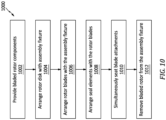
- FIG. 10 is a flow diagram of a method 1000 for assembling a bladed rotor using an assembly fixture.
- the assembly method 1000 of FIG. 10 is described with respect to the bladed rotor 20 and the assembly fixture 100.
- the assembly method 1000 of the present disclosure is not limited to assembling such an exemplary bladed rotor and/or using such an exemplary assembly fixture.
- step 1002 components of the bladed rotor 20 to be assembled are provided. These rotor components include, but are not limited to, the rotor disk 24, the rotor blades 26 and the seal elements 28.
- the rotor disk 24 is arranged with the assembly fixture 100.
- the rotor disk 24 is disposed on top of the disk support structure 104.
- the radial locator 116 may project axially into the disk bore 44.
- the radial locator outer surface 126 may radially engage the disk hub 38 (e.g., directly / contact, or indirectly through the bushing 120).
- the radial locator 116 may thereby radially locate the rotor disk 24 on the disk support structure 104.
- the disk hub 38 may axially engage (e.g., contact) the structure base top surface 122, and the disk rim 42 may axially engage (e.g., contact) the axial locator top surface 128.
- the top surface(s) 122 and/or 128 may thereby axially locate the rotor disk 24 with the disk support structure 104.
- step 1006 the rotor blades 26 are arranged with the assembly fixture 100.
- each of the blade attachments 66 is inserted vertically downward relative to gravity (e.g., axially along the axis 22, 102) partially into a respective one of the retaining slots 60.
- an axial (e.g., leading) edge 160 of each of the blade platforms 68 axially engages (e.g., contacts) and rests on top of the top surface 146.
- All of the blade platforms 68 and, thus, all of the rotor blades 26 may thereby be located at a common axial position along the axis 22, 102 and the axial edges 160 of the blade platforms 68 may define a horizontal reference plane perpendicular to the axis 22, 102; e.g., the plane of the top surface 146.
- the seal elements 28 are arranged with the rotor blades 26.
- each of the seal elements 28 is inserted into a respective one of the seal element cavities 94.
- the geometries of the pockets 90 and 92 and/or the geometry of the respective seal element 28 may allow at least a portion of that seal element 28 to lean radially outward towards (e.g., against) the respective blade platforms 68 while the rotor disk 24 is in its horizontal position on the disk support structure 104.
- the blade attachments 66 are simultaneously seated in the retaining slots 60.
- the blade support structure 106 may be rotated about the axis 22, 102 (relative to the disk support structure 104 of FIG. 2 ) such that each guide 156 moves within the respective slot 148 from a first (e.g., bottom) position 162A to a second (e.g., top) position 162B.
- the movement of each guide 156 within the respective slot 148 movement the rotational movement of the blade support structure 106 about the axis 22, 102 into axial translation of the blade support structure 106 in a vertically downward direction along the axis 22, 102 and the rotor disk 24.
- This vertical downward movement of the blade support structure 106 facilitates controlled vertical downward movement of the blade attachments 66 into the retaining slots 60 until each of the blade attachments 66 is (e.g., completely) seated within its respective retaining slot 60; e.g., see FIG. 4 .
- the vertical downward movement of the blade support structure 106 controls the vertical downward movement of the rotor blades 26 and their blade attachments 66, the rotor blades 26 may (e.g., only) be pushed vertically downward by a force of gravity.
- step 1012 the bladed rotor 20 and its components 24, 26 and 28 are removed from the assembly fixture 100.
- the bladed rotor 20, for example, may be lifted vertically off of the assembly fixture 100 for subsequent assembly steps and/or installation within the gas turbine engine.
- assembly method 1000 is described with respect to assembling the rotor blades 26 and the seal elements 28 with the rotor disk 24, it is contemplated this assembly method 1000 may also be used to assemble rotor blades with a rotor disk without also simultaneously installing the seal elements 28.
- the bladed rotor 20 may be configured as a turbine rotor for a turbine section of the gas turbine engine. However, in other embodiments, the bladed rotor 20 may be configured as a compressor rotor for a compressor section of the gas turbine engine. In still other embodiments, the bladed rotor 20 may be configured as a fan rotor for a fan section of the gas turbine engine.
- FIG. 14 illustrates an example of the gas turbine engine which may include the bladed rotor 20 described above.
- This gas turbine engine of FIG. 14 is configured as a turbofan gas turbine engine 164.
- the gas turbine engine 164 of FIG. 14 extends along an axial centerline 166 of the gas turbine engine 164 between an upstream airflow inlet 168 and a downstream airflow exhaust 170, which axial centerline 166 may be parallel with (e.g., coaxial with) the axis 22.
- the gas turbine engine 164 includes a fan section 172, a compressor section 173, a combustor section 174 and a turbine section 175.
- the fan section 172 includes a fan rotor 178.
- the compressor section 173 includes a compressor rotor 179.
- the turbine section 175 includes a high pressure turbine (HPT) rotor 180 and a low pressure turbine (LPT) rotor 181, where the LPT rotor 181 is configured as a power turbine rotor.
- HPT high pressure turbine
- LPT low pressure turbine
- Each of these rotors 178-181 includes a plurality of rotor blades arranged circumferentially around and connected to one or more respective rotor disks. Any one of these rotors 178-181 may be configured as or otherwise include the bladed rotor 20.
- the fan rotor 178 is connected to the LPT rotor 181 through a low speed shaft 184.
- the compressor rotor 179 is connected to the HPT rotor 180 through a high speed shaft 186.
- the low speed shaft 184 extends through a bore of the high speed shaft 186 between the fan rotor 178 and the LPT rotor 181.
- This air is directed through the fan section 172 and into a core flowpath 188 and a bypass flowpath 190.
- the core flowpath 188 extends sequentially through the engine sections 173-175; e.g., a core of the gas turbine engine 164.
- the air within the core flowpath 188 may be referred to as "core air”.
- the bypass flowpath 190 extends through a bypass duct, which bypasses the engine core.
- the air within the bypass flowpath 190 may be referred to as "bypass air”.
- the core air is compressed by the compressor rotor 179 and directed into a (e.g., annular) combustion chamber 192 of a (e.g., annular) combustor 194 in the combustor section 174.
- Fuel is injected into the combustion chamber 192 via one or more of the fuel injectors 196 and mixed with the compressed core air to provide a fuel-air mixture.
- This fuel-air mixture is ignited and combustion products thereof flow through and sequentially cause the HPT rotor 180 and the LPT rotor 181 to rotate.
- the rotation of the HPT rotor 180 drives rotation of the compressor rotor 179 and, thus, compression of air received from an inlet into the core flowpath 188.
- the rotation of the LPT rotor 181 drives rotation of the fan rotor 178, which propels bypass air through and out of the bypass flowpath 190.
- the propulsion of the bypass air may account for a significant portion (e.g., a majority) of thrust generated by the turbine engine.
- the bladed rotor 20 may be configured with various gas turbine engines other than the one described above.
- the bladed rotor 20, for example, may be configured with a geared gas turbine engine where a geartrain connects one or more shafts to one or more rotors in a fan section, a compressor section and/or any other engine section.
- the bladed rotor 20 may be configured with a gas turbine engine configured without a geartrain.
- the bladed rotor 20 may be configured with a geared or non-geared gas turbine engine configured with a single spool, with two spools (e.g., see FIG. 14 ), or with more than two spools.
- the gas turbine engine may be configured as a turbofan engine, a turbojet engine, a turboprop engine, a turboshaft engine, a propfan engine, a pusher fan engine or any other type of gas turbine engine.
- the gas turbine engine may alternatively be configured as an auxiliary power unit (APU) or an industrial gas turbine engine.
- APU auxiliary power unit
- the present disclosure therefore is not limited to any particular types or configurations of gas turbine engines.
Landscapes
- Engineering & Computer Science (AREA)
- Mechanical Engineering (AREA)
- General Engineering & Computer Science (AREA)
- Turbine Rotor Nozzle Sealing (AREA)
Abstract
A method is provided for assembling a rotor of a gas turbine engine. During this method, a rotor disk (24) is provided that includes an axis (22; 102) and a plurality of slots (60) arranged circumferentially about the axis (22; 102) in an array. A plurality of rotor blades (26) are provided that include a plurality of airfoils (64) and a plurality of attachments (66). Each of the rotor blades (26) includes a respective one of the airfoils (64) and a respective one of the attachments (66). Each of the attachments (66) is inserted partially into a respective one of the slots (60). The rotor blades (26) are rested on top of a blade support structure (106). The blade support structure (106) is lowered axially downward along the rotor disk (24) to simultaneously seat the attachments (66) into the slots.
Description
- This disclosure (invention) relates generally to a gas turbine engine and, more particularly, to methods and tools for assembling a bladed rotor for the gas turbine engine.
- A gas turbine engine includes multiple bladed rotors such as, but not limited to, a fan rotor, a compressor rotor and a turbine rotor. Each bladed rotor may include a rotor disk and a plurality of rotor blades mechanically attached to the rotor disk. The bladed rotor may also include feather seals for sealing inter-platform gaps between circumferentially neighboring rotor blades. Various methods and tools are known in the art for assembling a bladed rotor. While these known assembly methods and tools have various advantages, there is still room in the art for improvement.
- According to an aspect of the invention, a method is provided for assembling a rotor of a gas turbine engine. During this method, a rotor disk is provided that includes an axis and a plurality of slots arranged circumferentially about the axis in an array. A plurality of rotor blades are provided that include a plurality of airfoils and a plurality of attachments. Each of the rotor blades includes a respective one of the airfoils and a respective one of the attachments. Each of the attachments is inserted partially into a respective one of the slots. The rotor blades are rested on top of a blade support structure. The blade support structure is lowered axially downward along the rotor disk to simultaneously seat the attachments into the slots.
- According to another aspect of the invention, another method is provided for assembling a rotor of a gas turbine engine. During this method, a rotor disk, a plurality of rotor blades and a plurality of seal elements are provided. The rotor disk includes an axis and a plurality of slots arranged circumferentially about the axis in an array. The rotor blades include a plurality of airfoils and a plurality of attachments. Each of the rotor blades includes a respective one of the airfoils and a respective one of the attachments. Each of the attachments is inserted partially into a respective one of the slots. Each of the seal elements is arranged between a respective circumferentially neighboring pair of the rotor blades. The attachments are simultaneously seated into the slots using a force of gravity alone to push the attachments into the slots.
- According to still another aspect of the invention, a fixture is provided for assembling a rotor of a gas turbine engine. This assembly fixture includes a disk support structure and a blade support structure. The disk support structure is configured to support a rotor disk of the rotor during assembly of the rotor. The disk support structure includes a base, a radial locator and an axial locator circumscribing the radial locator. The radial locator projects axially along an axis out from a first side of the base. The radial locator is configured to radially locate and engage the rotor disk on the disk support structure. The axial locator projects axially along the axis out from the first side of the base. The axial locator is configured to axially locate and engage the rotor disk on the disk support structure. The blade support structure is configured to support a plurality of rotor blades of the rotor during the assembly of the rotor. The blade support structure circumscribes and is slidable against an outer periphery of the disk support structure. The blade support structure extends axially along the axis to a planar annular surface configured to axially locate and engage the rotor blades while attachments of the rotor blades are seated in slots in the rotor disk.
- The following optional features may be applied to any of the above aspects of the invention.
- The assembly fixture may also include a guide connected to the disk support structure and projecting radially into a slot in the blade support structure. The slot may extend within the blade support structure along a longitudinal trajectory. A first section of the longitudinal trajectory may have an axial component and a circumferential component. A second section of the longitudinal trajectory may have a circumferential component.
- The assembly fixture may also include a lock configured to rotatably fix the blade support structure to the disk support structure.
- The rotor blades may also include a plurality of platforms. Each of the rotor blades may also include a respective one of the platforms. Axial edges of the platforms may define a reference plane while the attachments are seated into the slots.
- The method may also include resting the axial edges of the platforms on top of a planar annular surface of a blade support structure as the attachments are seated into the slots.
- Gravity may maintain the rotor blades resting on top of the blade support structure as the blade support structure is lowered axially downward along the rotor disk.
- The method may also include: providing a plurality of seal elements; and inserting each of the seal elements into a respective cavity formed by and between a respective circumferentially neighboring pair of the rotor blades.
- Each of the seal elements may be inserted into the respective cavity prior to the lowering of the blade support structure.
- Each of the seal elements may be inserted into the respective cavity subsequent to the inserting of each of the attachments partially into the respective one of the slots.
- The seal elements may include a first seal element. The first seal element may include a base and a plurality of tabs connected to and projecting out from the base.
- Each of the tabs may project radially inward from the base to a distal tab end.
- The rotor disk may also include a plurality of lugs. Each of the slots may be formed by and between a respective circumferentially neighboring pair of the lugs. A first of the lugs may project radially outward to a distal lug end including a first end surface and a second end surface recessed radially inward from the first end surface. Subsequent to the attachments being simultaneously seated into the slots, a first of the tabs may be operable to radially engage the first end surface and a second of the tabs may be operable to radially engage the second end surface.
- The rotor blades may be rested on a planar annular surface of the blade support structure.
- The rotor blades may also include a plurality of platforms. Each of the rotor blades may include a respective one of the platforms. The resting of the rotor blades may include resting axial edges of the platforms on top of the planar annular surface.
- The method may also include rotating the blade support structure about the axis while the blade support structure is lowered axially downward along the rotor disk.
- The method may also include disposing the rotor disk on top of a disk support structure. The blade support structure may be mated with and circumscribe the disk support structure.
- The method may also include lifting the rotor off of an assembly fixture. The rotor may include the rotor disk and the rotor blades. The assembly fixture may include the blade support structure.
- The rotor disk may include a turbine disk of the gas turbine engine. The rotor blades may include a plurality of turbine blades of the gas turbine engine.
- The invention may include any one or more of the individual features disclosed above and/or below alone or in any combination thereof.
- The foregoing features and the operation of the invention will become more apparent in light of the following description and the accompanying drawings.
-
-
FIG. 1 is a schematic illustration of a bladed rotor for a gas turbine engine. -
FIG. 2 is a partial side sectional schematic illustration of a rotor disk. -
FIG. 3 is a partial cross-sectional schematic illustration of the bladed rotor. -
FIG. 4 is a partial side sectional schematic illustration of the bladed rotor. -
FIG. 5A is a partial side sectional schematic illustration of the bladed rotor with a seal element at an operational position. -
FIG. 5B is a partial side sectional schematic illustration of the bladed rotor with a seal element at a nonoperational position. -
FIG. 6 is a partial perspective illustration of the bladed rotor, where the bladed rotor is shown with a single rotor blade and a single seal element for ease of illustration. -
FIG. 7 is a perspective illustration of a fixture for assembling a bladed rotor, where the bladed rotor is shown with a single rotor blade for ease of illustration, and where a blade support structure of the assembly fixture is depicted as semi-transparent. -
FIG. 8 is a perspective illustration of a disk support structure for the assembly fixture. -
FIG. 9 is a perspective illustration of the blade support structure shown in semi-transparent form. -
FIG. 10 is a flow diagram of a method for assembling a bladed rotor. -
FIG. 11 is a side sectional illustration of the rotor disk arranged with the assembly fixture. -
FIG. 12 is a partial side sectional illustration of the rotor disk and each rotor blade arranged with the assembly fixture. -
FIG. 13 is a partial side illustration of the blade support structure at a slot, where a guide has moved from a first (dashed line) position to a second (solid line) position. -
FIG. 14 is a side sectional schematic illustration of a gas turbine engine with which the bladed rotor may be arranged. -
FIG. 1 schematically illustrates abladed rotor 20 for a gas turbine engine. Thisbladed rotor 20 is rotatable about arotational axis 22, whichrotational axis 22 is also an axial centerline of thebladed rotor 20. Thebladed rotor 20 ofFIG. 1 includes arotor disk 24 and a plurality ofrotor blades 26 attached to and arranged circumferentially around therotor disk 24 in a circular array. Thebladed rotor 20 ofFIG. 1 also includes a plurality ofseal elements 28; e.g., feather seals. - Referring to
FIG. 2 , therotor disk 24 extends radially between and to a radialinner side 30 of therotor disk 24 and a radialouter side 32 of therotor disk 24. Therotor disk 24 extends axially along theaxis 22 between and to an axial first (e.g., upstream)side 34 of therotor disk 24 and an axial second (e.g., downstream)side 36 of therotor disk 24. Referring toFIG. 1 , therotor disk 24 extends circumferentially around theaxis 22 providing therotor disk 24 with an annular body. Therotor disk 24 includes adisk hub 38, adisk web 40 and adisk rim 42. - The
disk hub 38 is disposed at the diskinner side 30. Thedisk hub 38 forms abore 44 through therotor disk 24 along theaxis 22 between the diskfirst side 34 and the disksecond side 36; see alsoFIG. 2 . - The
disk web 40 is disposed radially between and connected to (e.g., formed integral with) thedisk hub 38 and thedisk rim 42. Thedisk web 40 ofFIG. 1 extends radially out from thedisk hub 38 to thedisk rim 42. - The disk rim 42 is disposed at the disk
outer side 32. The disk rim 42 forms a radial outer periphery of therotor disk 24. The disk rim 42 includes anannular rim base 46 and a plurality of rotor disk lugs 48 connected to (e.g., formed integral with) therim base 46. The disk lugs 48 are arranged circumferentially about theaxis 22 in a circular array. Referring toFIG. 2 , each of the disk lugs 48 projects radially out from therim base 46 to a radial outer distal lug end 50 of therespective disk lug 48. Thisdistal lug end 50 may have a stepped geometry. The distal lug end 50 ofFIG. 2 , for example, includes afirst end surface 52 and asecond end surface 54 recessed radially inward from thefirst end surface 52. Each of the disk lugs 48 extends axially along theaxis 22 between and to the diskfirst side 34 and the disksecond side 36. Referring toFIG. 3 , each of the disk lugs 48 extends circumferentially about theaxis 22 between and to a circumferentialfirst side 56 of therespective disk lug 48 and a circumferentialsecond side 58 of therespective disk lug 48. - The disk lugs 48 are configured to provide the
rotor disk 24 with a plurality of retainingslots 60. Each of the retainingslots 60 is formed by and extends circumferentially between a respective circumferentially neighboring (e.g., adjacent) pair of the disk lugs 48. Each retainingslot 60 ofFIG. 3 , for example, extends circumferentially within therotor disk 24 and itsdisk rim 42 between and to the lugfirst side 56 of a first of the circumferentially neighboring pair of the disk lugs 48 and the lugsecond side 58 of a second of the circumferentially neighboring pair of the disk lugs 48. Referring toFIG. 2 , each retainingslot 60 projects radially into therotor disk 24 and its disk rim 42 from the diskouter side 32 to a bottom 62 of therespective retaining slot 60. Each of the retainingslots 60 may extend axially through therotor disk 24 and itsdisk rim 42 along theaxis 22 between and to the diskfirst side 34 and the disksecond side 36. Examples of the retainingslots 60 include, but are not limited to, a firtree slot and a dovetail slot. - Referring to
FIG. 4 , each of therotor blades 26 includes ablade airfoil 64 and ablade attachment 66; e.g., a blade root. Each of therotor blades 26 may also include ablade platform 68 radially between and connected to (e.g., formed integral with) theblade airfoil 64 and theblade attachment 66. - The
blade airfoil 64 projects spanwise along a span line (e.g., radially away from the axis 22) from theblade platform 68 to a (e.g., unshrouded)tip 70 of theblade airfoil 64. Theblade airfoil 64 extends chordwise along a chord line (e.g., generally axially along the axis 22) between and to aleading edge 72 of theblade airfoil 64 and a trailingedge 74 of theblade airfoil 64. Referring toFIG. 3 , theblade airfoil 64 extends laterally between and to a first (e.g., concave, pressure)side 76 of theblade airfoil 64 and a second (e.g., convex, suction)side 78 of theblade airfoil 64. Referring toFIGS. 3 and4 , the airfoilfirst side 76 and the airfoilsecond side 78 each extend chordwise to and meet at theairfoil leading edge 72 and theairfoil trailing edge 74. The airfoilfirst side 76 and the airfoilsecond side 78 also extend spanwise from theblade platform 68 to and may meet at theairfoil tip 70. - The
blade attachment 66 ofFIG. 4 extends axially along theaxis 22 between and to an axial first (e.g., upstream) end 80 of theblade attachment 66 and an axial second (e.g., downstream) end 82 of theblade attachment 66. Theblade attachment 66 projects radially inward towards theaxis 22 from theblade platform 68 to a radial innerdistal attachment end 84 of theblade attachment 66. Referring toFIG. 3 , theblade attachment 66 extends circumferentially between and to a circumferentialfirst side 86 of theblade attachment 66 and a circumferentialsecond side 88 of theblade attachment 66. The attachmentfirst side 86 and the attachmentsecond side 88 are contoured to mate with contours of a respective one of the retainingslots 60. Theblade attachment 66, for example, may be configured as a blade root such as, but not limited to, a firtree root or a dovetail root. With such a configuration, eachblade attachment 66 and its blade root may be seated within therespective retaining slot 60 to mount therespective rotor blade 26 to therotor disk 24. It should be noted however, while theblade attachment 66 may consist of (e.g., only include) the blade root, it is contemplated theblade attachment 66 may also include a neck between the blade root and theblade platform 68 in other embodiments. - Referring to
FIG. 3 , theblade attachment 66 includes one ormore pockets first pocket 90 is disposed on the attachmentsecond side 88. Thesecond pocket 92 is disposed on the attachmentfirst side 86. Each of thesepockets blade attachment 66 from therespective attachment side pockets rotor blade 26 to a radial outer pocket side; e.g., formed by a radial inner side of theblade platform 68. Referring toFIG. 4 , each of thepockets blade attachment 66 between and to an axial first pocket end and an axial second pocket end. - Referring to
FIGS. 3 and4 , each of theseal elements 28 is disposed in aseal element cavity 94 formed by and circumferentially between a respective circumferentially neighboring pair of therotor blades 26. Thiscavity 94 may include thefirst pocket 90 in a first of the circumferentially neighboring pair of therotor blades 26 and thesecond pocket 92 in a second of the circumferentially neighboring pair of therotor blades 26. Referring toFIG. 5A , during gas turbine engine operation and/or while therotor disk 24 is rotating about itsaxis 22, eachseal element 28 may be forced radially outward and radially engage (e.g., contact) undersides of therespective blade platforms 68. Eachseal element 28 may thereby seal a circumferential gap between a respective circumferentially neighboring pair of theblade platforms 68. However, referring toFIG. 5B , eachseal element 28 may rest against the distal lug end 50 of arespective disk lug 48 when the gas turbine engine is nonoperational and/or while therotor disk 24 is stationary. - Referring to
FIG. 6 , each of theseal elements 28 may include anelement base 96 and one or more element tabs 98 (e.g., 98A-D). Each of the element tabs 98 is connected to (e.g., formed integral with) theelement base 96. Each of the element tabs 98 projects (e.g., radially inward towards the axis 22) out from theelement base 96 to a distal tab end of the respective element tab 98. Thefirst end tab 98A may be arranged at an axial first (e.g., upstream) end of therespective seal element 28. Thesecond end tab 98B may be arranged at an axial second (e.g., downstream) end of therespective seal element 28 that is axially opposite the element first end. The first side tab(s) 98C are arranged along a circumferential first side of therespective seal element 28. The second side tab(s) 98D are arranged along a circumferential second side of therespective seal element 28. The element tabs 98 may thereby provide eachseal element 28 with a bumpy, undulating radial inner geometry. Furthermore, while therotor disk 24 is stationary, one or more of the element tabs 98 (e.g., 98B, 98C, 98D) may radially engage (e.g., contact) the respectivefirst end surface 52 and one or more of the element tabs 98 (e.g., 98A, 98C, 98D) may radially engage the respectivesecond end surface 54. With such a configuration, it may be difficult to insert theseal elements 28 into thecavities 94 during bladed rotor assembly, particularly where theseal element 28 and any one or more of its element tabs 98 slide along the distal lug ends 50 and its end surfaces 52 and 54. -
FIG. 7 illustrates afixture 100 for use in assembling a bladed rotor such as, but not limited to, the bladed rotor 20 (shown in disassembled form and with onerotor blade 26 inFIG. 7 for ease of illustration). Thisassembly fixture 100 has a centerline axis 102, which centerline axis 102 may be coaxial with therotational axis 22 during assembly of thebladed rotor 20. The centerline axis 102 ofFIG. 7 is arranged vertically with respect to gravity for assembly of thebladed rotor 20 such that the centerline axis 102 is perpendicular to a horizon line. Theassembly fixture 100 ofFIG. 7 includes a stationarydisk support structure 104 and a movableblade support structure 106. - Referring to
FIG. 8 , thedisk support structure 104 extends axially along theaxis 22, 102 between and to an axialbottom side 108 of thedisk support structure 104 and an axialtop side 110 of thedisk support structure 104. Thedisk support structure 104 extends radially out from theaxis 22, 102 to a radialouter side 112 of thedisk support structure 104. Thedisk support structure 104 extends circumferentially around theaxis 22, 102 providing thedisk support structure 104 with a full-hoop body. Thedisk support structure 104 includes astructure base 114, aradial locator 116 and anaxial locator 118. Thedisk support structure 104 may also include a (e.g., removable) bushing 120 (e.g., a spacer, an adaptor, etc.) mounted on theradial locator 116. - The
structure base 114 is disposed at the structurebottom side 108. Thestructure base 114, for example, extends axially along theaxis 22, 102 from the structurebottom side 108 to a planar, annulartop surface 122 of thestructure base 114. Thestructure base 114 projects radially out from theaxis 22, 102 to a cylindricalouter surface 124 of thedisk support structure 104 at the structureouter side 112. - The
radial locator 116 is connected to (e.g., formed integral with) thestructure base 114 and disposed at thestructure top side 110. Theradial locator 116, for example, projects axially along theaxis 22, 102 out from thestructure base 114 to thestructure top side 110. Theradial locator 116 projects radially out from theaxis 22, 102 to a cylindricalouter surface 126 of theradial locator 116, which surface 126 is covered by thebushing 120 inFIG. 8 . The radial locatorouter surface 126 extends axially from the structure basetop surface 122 to thestructure top side 110. - The
axial locator 118 is connected to (e.g., formed integral with) thestructure base 114 and disposed at (or towards) thestructure top side 110. Theaxial locator 118, for example, projects axially along theaxis 22, 102 out from thestructure base 114 to an annular, planartop surface 128 of theaxial locator 118. The axial locatortop surface 128 may be axially recessed inward from thestructure top side 110 by an axial distance such that an axial height of theradial locator 116 is greater than an axial height of theaxial locator 118; however, the present disclosure is not limited to such an exemplary dimensional relationship. Theaxial locator 118 extends radially between and to a cylindricalinner surface 130 of theaxial locator 118 and the structureouter surface 124. The axial locatorinner surface 130 extends axially from the structure basetop surface 122 to the axial locatortop surface 128. The axial locatortop surface 128 extends radially between and to the axial locatorinner surface 130 and the structureouter surface 124. - Referring to
FIG. 9 , theblade support structure 106 includes atubular sidewall 132 and one or more handles 134. Thestructure sidewall 132 extends axially along theaxis 22, 102 between and to an axialbottom side 136 of theblade support structure 106 and an axialtop side 138 of theblade support structure 106. Thestructure sidewall 132 extends radially between and to a radialinner side 140 of theblade support structure 106 and a radialouter side 142 of thestructure sidewall 132. Thestructure sidewall 132 extends circumferentially around theaxis 22, 102 providing thestructure sidewall 132 with a tubular body. - The
structure sidewall 132 ofFIG. 9 has a cylindricalinner surface 144 at the structureinner side 140 and an annular, planartop surface 146 at thestructure top side 138. Thestructure sidewall 132 also includes one or more slots 148 (e.g., guide tracks) arranged circumferentially about theaxis 22, 102. Each of theslots 148 extends radially through thestructure sidewall 132 between the structureinner side 140 and the sidewallouter side 142. Each of theslots 148 ofFIG. 9 extends longitudinally within thestructure sidewall 132 along a longitudinal trajectory 150 (e.g., centerline) of therespective slot 148; see alsoFIG. 13 . A first (e.g., top)section 152 of the longitudinal trajectory 150 (e.g., only) has an axial component and a circumferential component, where the circumferential component is greater than the axial component. A second (e.g., bottom)section 154 of the longitudinal trajectory 150 (e.g., only) has an axial component. An axial length of thesecond section 154 may be smaller than an axial length of thefirst section 152. - The
handles 134 are disposed on opposing radial sides of thestructure sidewall 132. Each of thehandles 134 is connected (e.g., mechanically fastened) to thestructure sidewall 132. Each of thehandles 134 projects radially out from the sidewallouter side 142. - Referring to
FIG. 7 , theblade support structure 106 is mated with thedisk support structure 104. Thedisk support structure 104, for example, is inserted axially into a bore of theblade support structure 106. Theblade support structure 106 and itsstructure sidewall 132 thereby circumscribe thedisk support structure 104. The sidewall inner surface 144 (seeFIG. 9 ) radially engages (e.g., contacts) and is moveable against (e.g., slidable along) the structure outer surface 124 (seeFIG. 8 ); see alsoFIG. 11 . A plurality of guides 156 (e.g., posts, fasteners, pins, etc.) are attached to thedisk support structure 104; see alsoFIG. 8 . Each of theseguides 156 projects radially out from the structure outer surface 124 (seeFIG. 8 ) into a respective one of theslots 148. One or more locks 158 (e.g., fastener, threaded knobs, plungers, etc.) may be provided, where eachlock 158 is configured to rotationally fix theblade support structure 106 to thedisk support structure 104. A post of eachlock 158, for example, may extend through a lock aperture in thestructure sidewall 132 and project into a threaded aperture in thedisk support structure 104. However, theselocks 158 may be removed (e.g., pulled out, etc.) for seating theblade attachments 66 into the retainingslots 60, for example, as described below. -
FIG. 10 is a flow diagram of amethod 1000 for assembling a bladed rotor using an assembly fixture. For ease of description, theassembly method 1000 ofFIG. 10 is described with respect to thebladed rotor 20 and theassembly fixture 100. Theassembly method 1000 of the present disclosure, however, is not limited to assembling such an exemplary bladed rotor and/or using such an exemplary assembly fixture. - In
step 1002, components of thebladed rotor 20 to be assembled are provided. These rotor components include, but are not limited to, therotor disk 24, therotor blades 26 and theseal elements 28. - In
step 1004, therotor disk 24 is arranged with theassembly fixture 100. For example, referring toFIG. 11 , therotor disk 24 is disposed on top of thedisk support structure 104. Theradial locator 116 may project axially into the disk bore 44. The radial locatorouter surface 126 may radially engage the disk hub 38 (e.g., directly / contact, or indirectly through the bushing 120). Theradial locator 116 may thereby radially locate therotor disk 24 on thedisk support structure 104. Thedisk hub 38 may axially engage (e.g., contact) the structure basetop surface 122, and thedisk rim 42 may axially engage (e.g., contact) the axial locatortop surface 128. The top surface(s) 122 and/or 128 may thereby axially locate therotor disk 24 with thedisk support structure 104. - In
step 1006, therotor blades 26 are arranged with theassembly fixture 100. For example, while theblade support structure 106 is in a first (e.g., raised) position ofFIG. 12 (see alsoFIG. 7 ), each of theblade attachments 66 is inserted vertically downward relative to gravity (e.g., axially along theaxis 22, 102) partially into a respective one of the retainingslots 60. At this partially inserted position, an axial (e.g., leading)edge 160 of each of theblade platforms 68 axially engages (e.g., contacts) and rests on top of thetop surface 146. All of theblade platforms 68 and, thus, all of therotor blades 26 may thereby be located at a common axial position along theaxis 22, 102 and theaxial edges 160 of theblade platforms 68 may define a horizontal reference plane perpendicular to theaxis 22, 102; e.g., the plane of thetop surface 146. - In
step 1008, theseal elements 28 are arranged with therotor blades 26. For example, referring toFIG. 3 , each of theseal elements 28 is inserted into a respective one of theseal element cavities 94. Within thecavity 94, the geometries of thepockets respective seal element 28 may allow at least a portion of thatseal element 28 to lean radially outward towards (e.g., against) therespective blade platforms 68 while therotor disk 24 is in its horizontal position on thedisk support structure 104. - In step 1010, the
blade attachments 66 are simultaneously seated in the retainingslots 60. For example, referring toFIG. 13 , theblade support structure 106 may be rotated about theaxis 22, 102 (relative to thedisk support structure 104 ofFIG. 2 ) such that eachguide 156 moves within therespective slot 148 from a first (e.g., bottom)position 162A to a second (e.g., top)position 162B. The movement of eachguide 156 within therespective slot 148 movement the rotational movement of theblade support structure 106 about theaxis 22, 102 into axial translation of theblade support structure 106 in a vertically downward direction along theaxis 22, 102 and therotor disk 24. This vertical downward movement of theblade support structure 106 facilitates controlled vertical downward movement of theblade attachments 66 into the retainingslots 60 until each of theblade attachments 66 is (e.g., completely) seated within itsrespective retaining slot 60; e.g., seeFIG. 4 . Note, while the vertical downward movement of theblade support structure 106 controls the vertical downward movement of therotor blades 26 and theirblade attachments 66, therotor blades 26 may (e.g., only) be pushed vertically downward by a force of gravity. - In
step 1012, thebladed rotor 20 and itscomponents assembly fixture 100. Thebladed rotor 20, for example, may be lifted vertically off of theassembly fixture 100 for subsequent assembly steps and/or installation within the gas turbine engine. - While the
assembly method 1000 is described with respect to assembling therotor blades 26 and theseal elements 28 with therotor disk 24, it is contemplated thisassembly method 1000 may also be used to assemble rotor blades with a rotor disk without also simultaneously installing theseal elements 28. - In some embodiments, the
bladed rotor 20 may be configured as a turbine rotor for a turbine section of the gas turbine engine. However, in other embodiments, thebladed rotor 20 may be configured as a compressor rotor for a compressor section of the gas turbine engine. In still other embodiments, thebladed rotor 20 may be configured as a fan rotor for a fan section of the gas turbine engine. -
FIG. 14 illustrates an example of the gas turbine engine which may include thebladed rotor 20 described above. This gas turbine engine ofFIG. 14 is configured as a turbofangas turbine engine 164. Thegas turbine engine 164 ofFIG. 14 extends along an axial centerline 166 of thegas turbine engine 164 between anupstream airflow inlet 168 and adownstream airflow exhaust 170, which axial centerline 166 may be parallel with (e.g., coaxial with) theaxis 22. Thegas turbine engine 164 includes afan section 172, acompressor section 173, acombustor section 174 and aturbine section 175. - The
fan section 172 includes afan rotor 178. Thecompressor section 173 includes acompressor rotor 179. Theturbine section 175 includes a high pressure turbine (HPT)rotor 180 and a low pressure turbine (LPT)rotor 181, where theLPT rotor 181 is configured as a power turbine rotor. Each of these rotors 178-181 includes a plurality of rotor blades arranged circumferentially around and connected to one or more respective rotor disks. Any one of these rotors 178-181 may be configured as or otherwise include thebladed rotor 20. - The
fan rotor 178 is connected to theLPT rotor 181 through alow speed shaft 184. Thecompressor rotor 179 is connected to theHPT rotor 180 through ahigh speed shaft 186. Thelow speed shaft 184 extends through a bore of thehigh speed shaft 186 between thefan rotor 178 and theLPT rotor 181. - During operation, air enters the
gas turbine engine 164 through theairflow inlet 168. This air is directed through thefan section 172 and into acore flowpath 188 and abypass flowpath 190. Thecore flowpath 188 extends sequentially through the engine sections 173-175; e.g., a core of thegas turbine engine 164. The air within thecore flowpath 188 may be referred to as "core air". Thebypass flowpath 190 extends through a bypass duct, which bypasses the engine core. The air within thebypass flowpath 190 may be referred to as "bypass air". - The core air is compressed by the
compressor rotor 179 and directed into a (e.g., annular)combustion chamber 192 of a (e.g., annular)combustor 194 in thecombustor section 174. Fuel is injected into thecombustion chamber 192 via one or more of thefuel injectors 196 and mixed with the compressed core air to provide a fuel-air mixture. This fuel-air mixture is ignited and combustion products thereof flow through and sequentially cause theHPT rotor 180 and theLPT rotor 181 to rotate. The rotation of theHPT rotor 180 drives rotation of thecompressor rotor 179 and, thus, compression of air received from an inlet into thecore flowpath 188. The rotation of theLPT rotor 181 drives rotation of thefan rotor 178, which propels bypass air through and out of thebypass flowpath 190. The propulsion of the bypass air may account for a significant portion (e.g., a majority) of thrust generated by the turbine engine. - The
bladed rotor 20 may be configured with various gas turbine engines other than the one described above. Thebladed rotor 20, for example, may be configured with a geared gas turbine engine where a geartrain connects one or more shafts to one or more rotors in a fan section, a compressor section and/or any other engine section. Alternatively, thebladed rotor 20 may be configured with a gas turbine engine configured without a geartrain. Thebladed rotor 20 may be configured with a geared or non-geared gas turbine engine configured with a single spool, with two spools (e.g., seeFIG. 14 ), or with more than two spools. The gas turbine engine may be configured as a turbofan engine, a turbojet engine, a turboprop engine, a turboshaft engine, a propfan engine, a pusher fan engine or any other type of gas turbine engine. The gas turbine engine may alternatively be configured as an auxiliary power unit (APU) or an industrial gas turbine engine. The present disclosure therefore is not limited to any particular types or configurations of gas turbine engines. - While various embodiments of the present disclosure have been described, it will be apparent to those of ordinary skill in the art that many more embodiments and implementations are possible within the scope of the disclosure. For example, the present disclosure as described herein includes several aspects and embodiments that include particular features. Although these features may be described individually, it is within the scope of the present disclosure that some or all of these features may be combined with any one of the aspects and remain within the scope of the disclosure. Accordingly, the present disclosure is not to be restricted except in light of the attached claims and their equivalents.
Claims (15)
- A method for assembling a rotor (20) of a gas turbine engine (164), comprising:providing a rotor disk (24) that comprises an axis (22; 102) and a plurality of slots (60) arranged circumferentially about the axis (22; 102) in an array;providing a plurality of rotor blades (26) that include a plurality of airfoils (64) and a plurality of attachments (66), each of the plurality of rotor blades (26) including a respective one of the plurality of airfoils (64) and a respective one of the plurality of attachments (66);inserting each of the plurality of attachments (66) partially into a respective one of the plurality of slots (60);resting the plurality of rotor blades (26) on top of a blade support structure (106); andlowering the blade support structure (106) axially downward along the rotor disk (24) to simultaneously seat the plurality of attachments (66) into the plurality of slots (60).
- The method of claim 1, wherein gravity maintains the plurality of rotor blades (26) resting on top of the blade support structure (106) as the blade support structure (106) is lowered axially downward along the rotor disk (24).
- The method of claim 1 or 2, further comprising:providing a plurality of seal elements (28); andinserting each of the plurality of seal elements (28) into a respective cavity (94) formed by and between a respective circumferentially neighboring pair of the plurality of rotor blades (26).
- The method of claim 3, wherein each of the plurality of seal elements (28) is inserted into the respective cavity (94) prior to the lowering of the blade support structure (106), and optionally each of the plurality of seal elements (28) is inserted into the respective cavity (94) subsequent to the inserting of each of the plurality of attachments (66) partially into the respective one of the plurality of slots (60).
- The method of claim 3 or 4, wherein:the plurality of seal elements (28) comprise a first seal element (28);the first seal element (28) includes a base (96) and a plurality of tabs (98) connected to and projecting out from the base (96); andeach of the plurality of tabs (98) optionally projects radially inward from the base (96) to a distal tab end.
- The method of claim 5, whereinthe rotor disk (24) further comprises a plurality of lugs (48);each of the plurality of slots (60) is formed by and between a respective circumferentially neighboring pair of the plurality of lugs (48);a first of the plurality of lugs (48) projects radially outward to a distal lug end (50) including a first end surface (52) and a second end surface (54) recessed radially inward from the first end surface (52); andsubsequent to the plurality of attachments (66) being simultaneously seated into the plurality of slots (60), a first of the plurality of tabs (98B, 98C, 98D) is operable to radially engage the first end surface (52) and a second of the plurality of tabs (98A, 98C, 98) is operable to radially engage the second end surface (54).
- The method of any preceding claim, wherein the plurality of rotor blades (26) are rested on a planar annular surface (138) of the blade support structure (106).
- The method of claim 7, whereinthe plurality of rotor blades (26) further include a plurality of platforms (68), and each of the plurality of rotor blades (26) includes a respective one of the plurality of platforms (68); andthe resting of the plurality of rotor blades (26) comprises resting axial edges (160) of the plurality of platforms (68) on top of the planar annular surface (126).
- The method of any preceding claim, further comprising rotating the blade support structure (106) about the axis (22; 102) while the blade support structure (106) is lowered axially downward along the rotor disk (24).
- The method of any preceding claim, further comprising:disposing the rotor disk (24) on top of a disk support structure (104);the blade support structure (106) mated with and circumscribing the disk support structure (104).
- The method of any preceding claim, further comprising:lifting the rotor (20) off of an assembly fixture (100);the rotor (20) including the rotor disk (24) and the plurality of rotor blades (26); andthe assembly fixture (100) comprising the blade support structure (106).
- The method of any preceding claim, whereinthe rotor disk (24) comprises a turbine disk of the gas turbine engine (164); andthe plurality of rotor blades (26) comprise a plurality of turbine blades of the gas turbine engine (164).
- A method for assembling a rotor (20) of a gas turbine engine (164), comprising:providing a rotor disk (24), a plurality of rotor blades (26) and a plurality of seal elements (28), the rotor disk (24) comprising an axis (22; 102) and a plurality of slots (60) arranged circumferentially about the axis (22; 102) in an array, the plurality of rotor blades (26) including a plurality of airfoils (64) and a plurality of attachments (66), and each of the plurality of rotor blades (26) including a respective one of the plurality of airfoils (64) and a respective one of the plurality of attachments (66);inserting each of the plurality of attachments (66) partially into a respective one of the plurality of slots (60);arranging each of the plurality of seal elements (28) between a respective circumferentially neighboring pair of the plurality of rotor blades (26); andsimultaneously seating the plurality of attachments (66) into the plurality of slots (60) using a force of gravity alone to push the plurality of attachments (66) into the plurality of slots (60), optionally wherein:the plurality of rotor blades (26) further include a plurality of platforms (68), and each of the plurality of rotor blades (26) further includes a respective one of the plurality of platforms (68); andaxial edges (160) of the plurality of platforms (68) define a reference plane while the plurality of attachments (66) are seated into the plurality of slots (60),
and wherein the method optionally further comprises resting the axial edges (160) of the plurality of platforms (68) on top of a planar annular surface (126) of a blade support structure (106) as the plurality of attachments (66) are seated into the plurality of slots (60). - A fixture (100) for assembling a rotor (20) of a gas turbine engine (164), comprising:a disk support structure (104) configured to support a rotor disk (24) of the rotor (20) during assembly of the rotor (20), the disk support structure (104) including a base (114), a radial locator (116) and an axial locator (118) circumscribing the radial locator (116), the radial locator (116) projecting axially along an axis (22; 102) out from a first side (122) of the base (114), the radial locator (116) configured to radially locate and engage the rotor disk (24) on the disk support structure (104), the axial locator (118) projecting axially along the axis (22; 102) out from the first side (122) of the base (114), and the axial locator (118) configured to axially locate and engage the rotor disk (24) on the disk support structure (104); anda blade support structure (106) configured to support a plurality of rotor blades (26) of the rotor (20) during the assembly of the rotor (20), the blade support structure (106) circumscribing and slidable against an outer periphery of the disk support structure (104), the blade support structure (106) extending axially along the axis (22; 102) to a planar annular surface (138) configured to axially locate and engage the plurality of rotor blades (26) while attachments (66) of the plurality of rotor blades (26) are seated in slots (60) in the rotor disk (24),
optionally wherein the fixture (100) further comprises a lock (158) configured to rotatably fix the blade support structure (106) to the disk support structure (104). - The fixture (100) of claim 14, further comprising:a guide (156) connected to the disk support structure (104) and projecting radially into a slot (148) in the blade support structure (106);the slot (148) extending within the blade support structure (106) along a longitudinal trajectory (150);a first section (152) of the longitudinal trajectory (150) having an axial component and a circumferential component; anda second section (154) of the longitudinal trajectory (150) having a circumferential component.
Applications Claiming Priority (1)
| Application Number | Priority Date | Filing Date | Title |
|---|---|---|---|
| US17/891,789 US11808164B1 (en) | 2022-08-19 | 2022-08-19 | Simultaneously assembling rotor blades from a gas turbine engine rotor disk |
Publications (1)
| Publication Number | Publication Date |
|---|---|
| EP4332349A1 true EP4332349A1 (en) | 2024-03-06 |
Family
ID=87748346
Family Applications (1)
| Application Number | Title | Priority Date | Filing Date |
|---|---|---|---|
| EP23192217.0A Pending EP4332349A1 (en) | 2022-08-19 | 2023-08-18 | Simultaneously assembling rotor blades with a gas turbine engine rotor disk |
Country Status (3)
| Country | Link |
|---|---|
| US (1) | US11808164B1 (en) |
| EP (1) | EP4332349A1 (en) |
| CA (1) | CA3209460A1 (en) |
Citations (5)
| Publication number | Priority date | Publication date | Assignee | Title |
|---|---|---|---|---|
| US5737816A (en) * | 1995-06-02 | 1998-04-14 | Asea Brown Boveri Ag | Device for the mounting of rotating blades |
| US20080134503A1 (en) * | 2003-06-20 | 2008-06-12 | Harold Keith Crain | Methods and systems for assembling gas turbine engine fan assemblies |
| US20080193293A1 (en) * | 2007-02-08 | 2008-08-14 | Greenberg Michael D | Bladed disk assembly method and impact device |
| US20140304989A1 (en) * | 2011-10-28 | 2014-10-16 | Pratt & Whitney Canada Corp. | Rotor blade assembly tool for gas turbine engine |
| EP3327250A1 (en) * | 2016-11-23 | 2018-05-30 | General Electric Company | Installation or removal of turbine blade at turbine blade base |
Family Cites Families (1)
| Publication number | Priority date | Publication date | Assignee | Title |
|---|---|---|---|---|
| EP3336315B1 (en) | 2016-12-13 | 2021-09-15 | General Electric Company | Fixture for transfering turbine blades to a rotor wheel |
-
2022
- 2022-08-19 US US17/891,789 patent/US11808164B1/en active Active
-
2023
- 2023-08-15 CA CA3209460A patent/CA3209460A1/en active Pending
- 2023-08-18 EP EP23192217.0A patent/EP4332349A1/en active Pending
Patent Citations (5)
| Publication number | Priority date | Publication date | Assignee | Title |
|---|---|---|---|---|
| US5737816A (en) * | 1995-06-02 | 1998-04-14 | Asea Brown Boveri Ag | Device for the mounting of rotating blades |
| US20080134503A1 (en) * | 2003-06-20 | 2008-06-12 | Harold Keith Crain | Methods and systems for assembling gas turbine engine fan assemblies |
| US20080193293A1 (en) * | 2007-02-08 | 2008-08-14 | Greenberg Michael D | Bladed disk assembly method and impact device |
| US20140304989A1 (en) * | 2011-10-28 | 2014-10-16 | Pratt & Whitney Canada Corp. | Rotor blade assembly tool for gas turbine engine |
| EP3327250A1 (en) * | 2016-11-23 | 2018-05-30 | General Electric Company | Installation or removal of turbine blade at turbine blade base |
Also Published As
| Publication number | Publication date |
|---|---|
| CA3209460A1 (en) | 2024-02-19 |
| US11808164B1 (en) | 2023-11-07 |
Similar Documents
| Publication | Publication Date | Title |
|---|---|---|
| EP1835147B1 (en) | Fan assembly and corresponding gas turbine engine | |
| US7874794B2 (en) | Blade row for a rotary machine and method of fabricating same | |
| EP3640432B1 (en) | Turbine shroud assemblies for gas turbine engines | |
| EP1543918A2 (en) | Holding Device for Gas Turbine Rotor Blades and Machine Tool incorporating such a device | |
| EP3150803A1 (en) | Airfoil and method of cooling | |
| US10941671B2 (en) | Gas turbine engine component incorporating a seal slot | |
| EP2984290B1 (en) | Integrally bladed rotor | |
| EP3225794A1 (en) | Turbine engine shroud assembly | |
| US20210108569A1 (en) | Gas turbine engine with clutch assembly | |
| EP2964894A2 (en) | Turbine segmented cover plate retention method | |
| EP4332349A1 (en) | Simultaneously assembling rotor blades with a gas turbine engine rotor disk | |
| US11041395B2 (en) | Airfoils and core assemblies for gas turbine engines and methods of manufacture | |
| US11920498B2 (en) | Turbine circumferential dovetail leakage reduction | |
| US12000301B2 (en) | Simultaneously disassembling rotor blades from a gas turbine engine rotor disk | |
| EP4332355A1 (en) | Simultaneously disassembling rotor blades from a gas turbine engine rotor disk | |
| EP3296508B1 (en) | Full-span forward swept airfoils for gas turbine engines | |
| EP3578759B1 (en) | Airfoil and corresponding method of directing a cooling flow | |
| CN107806367B (en) | Rotatable machine and turbofan for preventing overspeed of rotor disc | |
| US12000292B1 (en) | Systems and methods for multi-dimensional variable vane stage rigging | |
| US12000293B1 (en) | Systems and methods for multi-dimensional variable vane stage rigging utilizing coupling mechanisms | |
| EP3869010B1 (en) | Tangential rotor blade slot spacer for a gas turbine engine | |
| EP4321733A1 (en) | Variable vane airfoil with recess to accommodate protuberance | |
| EP3708778B1 (en) | Inserts for slotted integrally bladed rotor | |
| EP4353952A1 (en) | Retention of a fan blade of a gas turbine engine | |
| US20220098987A1 (en) | Turbine blades including aero-brake features and methods for using the same |
Legal Events
| Date | Code | Title | Description |
|---|---|---|---|
| PUAI | Public reference made under article 153(3) epc to a published international application that has entered the european phase |
Free format text: ORIGINAL CODE: 0009012 |
|
| STAA | Information on the status of an ep patent application or granted ep patent |
Free format text: STATUS: THE APPLICATION HAS BEEN PUBLISHED |
|
| AK | Designated contracting states |
Kind code of ref document: A1 Designated state(s): AL AT BE BG CH CY CZ DE DK EE ES FI FR GB GR HR HU IE IS IT LI LT LU LV MC ME MK MT NL NO PL PT RO RS SE SI SK SM TR |