EP4332303B1 - Maschine zur bearbeitung einer betonoberfläche, verfahren zur bearbeitung einer folge von betonoberflächen und verfahren zur herstellung einer betonoberfläche - Google Patents
Maschine zur bearbeitung einer betonoberfläche, verfahren zur bearbeitung einer folge von betonoberflächen und verfahren zur herstellung einer betonoberfläche Download PDFInfo
- Publication number
- EP4332303B1 EP4332303B1 EP22193046.4A EP22193046A EP4332303B1 EP 4332303 B1 EP4332303 B1 EP 4332303B1 EP 22193046 A EP22193046 A EP 22193046A EP 4332303 B1 EP4332303 B1 EP 4332303B1
- Authority
- EP
- European Patent Office
- Prior art keywords
- machine
- tool
- wheels
- extension
- arm
- Prior art date
- Legal status (The legal status is an assumption and is not a legal conclusion. Google has not performed a legal analysis and makes no representation as to the accuracy of the status listed.)
- Active
Links
Images

Classifications
-
- E—FIXED CONSTRUCTIONS
- E01—CONSTRUCTION OF ROADS, RAILWAYS, OR BRIDGES
- E01C—CONSTRUCTION OF, OR SURFACES FOR, ROADS, SPORTS GROUNDS, OR THE LIKE; MACHINES OR AUXILIARY TOOLS FOR CONSTRUCTION OR REPAIR
- E01C19/00—Machines, tools or auxiliary devices for preparing or distributing paving materials, for working the placed materials, or for forming, consolidating, or finishing the paving
- E01C19/22—Machines, tools or auxiliary devices for preparing or distributing paving materials, for working the placed materials, or for forming, consolidating, or finishing the paving for consolidating or finishing laid-down unset materials
- E01C19/30—Tamping or vibrating apparatus other than rollers ; Devices for ramming individual paving elements
- E01C19/34—Power-driven rammers or tampers, e.g. air-hammer impacted shoes for ramming stone-sett paving; Hand-actuated ramming or tamping machines, e.g. tampers with manually hoisted dropping weight
- E01C19/40—Power-driven rammers or tampers, e.g. air-hammer impacted shoes for ramming stone-sett paving; Hand-actuated ramming or tamping machines, e.g. tampers with manually hoisted dropping weight adapted to impart a smooth finish to the paving, e.g. tamping or vibrating finishers
- E01C19/405—Power-driven rammers or tampers, e.g. air-hammer impacted shoes for ramming stone-sett paving; Hand-actuated ramming or tamping machines, e.g. tampers with manually hoisted dropping weight adapted to impart a smooth finish to the paving, e.g. tamping or vibrating finishers with spreading-out, levelling or smoothing means other than the tamping or vibrating means for compacting or smoothing, e.g. with screws for spreading-out the previously dumped material, with non-vibratory lengthwise reciprocated smoothing beam
-
- E—FIXED CONSTRUCTIONS
- E01—CONSTRUCTION OF ROADS, RAILWAYS, OR BRIDGES
- E01C—CONSTRUCTION OF, OR SURFACES FOR, ROADS, SPORTS GROUNDS, OR THE LIKE; MACHINES OR AUXILIARY TOOLS FOR CONSTRUCTION OR REPAIR
- E01C19/00—Machines, tools or auxiliary devices for preparing or distributing paving materials, for working the placed materials, or for forming, consolidating, or finishing the paving
- E01C19/22—Machines, tools or auxiliary devices for preparing or distributing paving materials, for working the placed materials, or for forming, consolidating, or finishing the paving for consolidating or finishing laid-down unset materials
- E01C19/42—Machines for imparting a smooth finish to freshly-laid paving courses other than by rolling, tamping or vibrating
-
- E—FIXED CONSTRUCTIONS
- E04—BUILDING
- E04F—FINISHING WORK ON BUILDINGS, e.g. STAIRS, FLOORS
- E04F21/00—Implements for finishing work on buildings
- E04F21/20—Implements for finishing work on buildings for laying flooring
- E04F21/24—Implements for finishing work on buildings for laying flooring of masses made in situ, e.g. smoothing tools
- E04F21/241—Elongated smoothing blades or plates, e.g. screed apparatus
-
- E—FIXED CONSTRUCTIONS
- E04—BUILDING
- E04F—FINISHING WORK ON BUILDINGS, e.g. STAIRS, FLOORS
- E04F21/00—Implements for finishing work on buildings
- E04F21/20—Implements for finishing work on buildings for laying flooring
- E04F21/24—Implements for finishing work on buildings for laying flooring of masses made in situ, e.g. smoothing tools
- E04F21/245—Rotary power trowels, i.e. helicopter trowels
- E04F21/247—Rotary power trowels, i.e. helicopter trowels used by an operator sitting on the trowel, i.e. ride-on power trowels
Definitions
- the present invention relates to a machine for treating a concrete surface.
- a machine equipped with a dedicated tool for this purpose.
- the tool is fixed against the frame of the machine, which moves as the surface is treated.
- This type of machine is typically small and low-powered. It is used for small surfaces.
- the document WO 2020/076468 A1 discloses such a machine generally referred to as "lightweight”.
- the tool is mechanically coupled to the end of a telescopic arm, called a "boom", so as to be movable above the surface in a direction of extension of the arm, from a base unit.
- the arm extending over distances generally of 4 to 9 meters, or even more, it is thus possible to quickly treat a surface in the form of a strip of concrete from a single position and orientation of the machine. It is precisely this type of machine with a boom which is the subject of the present invention.
- a known example of concrete surface treatment is the leveling of unset (or uncured) concrete, also known as screeding.
- documents EP3728739A1 , US 2007/0116520 A1 , And US 4,655,633 A each disclose an embodiment of a machine for leveling a concrete surface equipped with a boom.
- Such a machine generally comprises a hollow compartment for the arm arranged in an upper part of the base unit.
- the latter also comprises a lower part which is coupled to the upper part and around which the upper part can rotate to properly orient the arm and the tool in a given position of the machine.
- the movement of the machine can be obtained via two axles each carrying two wheels and fixed on the lower part.
- each of the two axles extends in the direction of extension, the axles being aligned in a direction orthogonal to that of the arm extension.
- the wheels thus allow the machine to be moved in this orthogonal direction between the treatment of two surfaces.
- this type of boom machine includes removable and/or adjustable stabilizing feet attached to the bottom to support the machine in position while treating the concrete surface. These stabilizing feet also allow the boom to be given the desired angle of attack. However, the stabilizing feet must be removed and/or adjusted both before and after treating each concrete surface. Positioning and stabilizing the machine, as well as the orientation of the boom, before treating a concrete surface therefore takes considerable time on site.
- a machine for treating a concrete surface having the features of claim 1 a method of treating a succession of similar concrete surfaces aligned along a guiding direction by means of such a machine having the features of claim 15 and a method of manufacturing a concrete surface comprising a use of such a machine having the features of claim 16.
- An object of the present invention is to provide such a machine with boom which allows concrete surfaces to be treated efficiently.
- axles are then fixed at two end portions of the frame, according to the direction of extension, the axles extending transversely, and preferably perpendicularly, to it.
- the axles are necessarily aligned according to the direction of extension, and arranged at end portions of the frame sufficiently distant from each other along the direction of extension so that the center of gravity of the machine overcomes or is in a space between the wheels, regardless of the configuration of the machine.
- the chassis is preferably referred to as central and/or main. It is preferably the only chassis of the machine. In particular, since the wheels are steerable, it is not necessary to provide two separate parts of a basic unit as described according to the prior art, the entire machine being able to be arranged on the basis of a single chassis elongated along the extension direction and steerable via the wheels. Since the compartment is formed in the chassis, an orientation of the chassis induces an orientation of the arm and therefore of the tool.
- the chassis is in particular directly connected to the steerable running gear of the machine as described above.
- the compartment is further preferably capable of containing at least at least 85% of the arm measured in the direction of extension, and preferably the entire arm, in a retracted configuration.
- the chassis also allows the masses of the machine to be distributed even more adequately to ensure that the center of gravity of the machine is positioned above or in a space between the wheels.
- heavy elements of the machine such as batteries or motors may be arranged at the end portion of the chassis opposite the tool to counterbalance the weight of the tool.
- a mass of a part of the machine extending in front of (in the direction of deployment of the arm along the extension direction) the axle fixed at the end portion of the chassis closest to the tool is typically less than a mass of a part of the machine extending behind this axle.
- the chassis' potential pitching is further limited by the arrangement of the wheels via the axles, with the running gear preferably being rigid.
- the wheels may include solid tires filled with silicone foam, which provides good wheel rigidity. This prevents the tires from crushing under arm movements when working on a concrete surface.
- concrete generally refers, in an unset (or uncured) state, to a flexible paste of variable homogeneity, preferably comprising a mixture of sand and cement, intended to be poured into a dedicated space prior to its hardening. This occurs after a setting time.
- the dedicated space is, for example, a support, a mold or a cavity. Concrete is a very widely known construction material which can be used to form coatings and construction elements of great strength.
- the concrete is preferably poured so as to form a concrete surface.
- treatment is likely to relate to different stages of the formation of this surface.
- the tool may be a tool for leveling the surface of unset concrete (an operation known as "screed") or a finishing tool for applying a finishing powder to the surface (an operation known as "spreading").
- surface is not to be understood in this document as referring to a strictly two-dimensional (mathematical) object.
- a concrete surface necessarily has a certain thickness of concrete.
- the term "surface” is used taking into account that, in general, the exterior surface of the concrete once set and treated is the one that is visible externally, typically during the design of a concrete covering, floor or slab.
- the unset concrete poured into the space dedicated to the formation of the surface generally includes irregularities and variations in thickness forming a relief, hence the need to level this surface with a machine provided for this purpose. This concrete therefore does not extend only two-dimensionally.
- the term "surface” is interchangeable with the term "extent”.
- the telescopic mechanical arm corresponds to a "boom" as introduced in the prior art. It will be understood by a person skilled in the art that such an arm is distinguished from attachment means holding the tool against the chassis or from a direct extension of less than 1 meter of these attachment means.
- the arm is preferably capable of extending along the extension direction by at least 4 meters, and preferably by a maximum extension length of between 4 and 9 meters, for example about 5.5 or 6.0 meters, typically when deployed, or alternatively of carrying the tool at this distance from the chassis.
- the term "primarily" in reference to a direction in which a part of the machine extends means that this part of the machine extends (significantly and/or visibly) more in this direction than in other basic directions in space.
- the frame of the machine extends primarily in the direction of extension of the arm, but of course also in the other two directions in space which are perpendicular to it and are perpendicular to each other.
- the frame extends in these two directions over a variable distance along the direction of extension and between 0.5 and 1.0 meters.
- At least two of the wheels, and more preferably, all the wheels are individually and/or independently steerable.
- Each wheel can thus be steered in a chosen manner independently of the other wheels, and in particular of any wheel coupled to the same axle. A wide range of movements of the machine is thus made possible as illustrated in Figure 2 hereinafter introduced.
- each pair formed by a wheel and a leg is thus able to turn relative to the rest of the axle, and therefore in particular relative to the chassis, via the turning means, preferably independently of the other such pairs.
- the wheels are thus completely steerable thanks to the simple and practical mechanical coupling of the legs with the axial part.
- the machine is more stable and more solid.
- the forces within the machine are in particular better absorbed at the level of the axles and the wheels.
- the two legs also make it possible to offset the wheels below the plane of the chassis, and preferably laterally offset from the chassis, which makes it all the more possible to support and stabilize the machine effectively.
- the axle is symmetrical on either side of the extension direction and/or the chassis, which which induces a generally symmetrical recovery of the efforts within the machine, and therefore the stability of the latter.
- the turning means comprise a turning motor mechanically coupled to a slewing ring.
- the motor is a hydraulic motor.
- the slewing ring preferably provides a rotational amplitude of at least 180°, preferably 360°. It is thus possible to steer the machine in all directions.
- These turning means thus form in particular a bearing.
- the slewing ring makes it possible to adequately transmit the power from the hydraulic motor for the purpose of rotating the leg.
- the slewing ring is preferably a ball bearing.
- each leg is arched. This shape allows the wheel to be partially surrounded to better support it and therefore better stabilize the machine as a whole.
- the upper and lower ends of the leg are aligned in a direction orthogonal to the direction of extension. The wheels thus extend under the chassis, at least partially laterally offset from it, this helping to effectively support the entire machine.
- This embodiment is very advantageous because it allows the machine operator the possibility of adjusting the elevation of the wheels via a control on the distance between the chassis and the wheels supported by the axle. It is thus possible to tilt the arm by varying the height of the axle, and therefore of the chassis at which it is fixed. This makes it possible to compensate for the curvature of the arm, at its extreme portion carrying the tool, due to the weight of the tool when the arm is deployed. It is quite sufficient to incorporate the elevation means in a single axle to obtain this technical effect.
- the chosen axle can be both the front axle (i.e. closest to the tool) and the rear axle (i.e. furthest from the tool) for example.
- distance between two objects refers to the shortest distance between two points each belonging to one of those objects.
- each leg of said axle provided with the lifting means comprises a pivot connection around which two parts of the leg are articulated.
- the lifting means preferably comprise a hydraulic cylinder arranged or coupled at this pivot connection.
- the hydraulic cylinder is, for example, coupled to a hydraulic motor forming part of the lifting means which can be arranged at the upper end of the leg.
- an electric motor is arranged in the chassis to move the arm by means of a belt, preferably toothed, engaged at the electric motor. It is thus possible to move (and therefore to extend from the compartment and to retract into the compartment) the arm solely via this electric motor and this belt, without using a hydraulic cylinder as in known machines.
- the machine according to the invention is all the more efficient because the drive power of the arm is thus no longer limited by the hydraulic cylinder: it is possible to use the electric motor to the maximum. This is particularly useful when the arm must be extended or retracted into the compartment without contact between the tool and the concrete (which is, for example, typically the case for a leveling tool when repositioning the tool at the start of a concrete surface).
- the belt typically mechanically couples the electric motor and the arm, by engagement on both sides.
- the belt is toothed to prevent possible slippage and transmit more torque between the arm and the electric motor.
- a toothed belt also has the advantage of being suitable for the arrangement of a rotation sensor (or encoder or coder) of the belt at the level of the belt or at the level of its drive by the electric motor. Specifically, this sensor is for example arranged on a belt drive pulley. This sensor can then be used to determine the position of the arm and/or the tool according to the number of revolutions made by the belt, for example, determined at the pulley.
- This data can then be used to regulate the speed of movement of the arm along the extension direction, in particular during its deployment, to prevent it from hitting the end of its stroke given its limited maximum extension length, which would risk damaging the belt and/or the electric motor.
- This regulation is in particular the subject of a method (A) explained below.
- the treatment tool is mechanically coupled to the end of the arm via a tool-carrying structure which is fixed to the end of the arm, and on either side of which are arranged two elevation cylinders carrying the tool to modify an elevation of the latter. It is thus made possible to adapt the height of the tool according to the quality and fluidity of the concrete, the desired leveling tolerance and/or other parameters.
- the two elevation cylinders are preferably hydraulic cylinders. However, other types of cylinders such as electric actuators would not depart from the scope of the invention.
- the determination of the elevation (or height) of the tool generally relies on a laser system as is known to a person skilled in the art. More precisely, a reference plane is generated, in the operating area of the machine, by means of a source of one or more laser beams. This reference plane can then be captured by receivers provided for this purpose and mounted on the tool. which ensures that the tool remains at a desired elevation relative to this reference plane. In the event of deviation from this desired elevation, the aforementioned elevation cylinders allow the tool elevation to be adjusted.
- the machine, especially the tool, and the machine's operating area are preferably equipped with this technology.
- this is very advantageous for leveling the surface sufficiently flat and at the correct height. This operation is often referred to as "laser screeding.”
- each of the elevation cylinders is preferably equipped with a position sensor.
- the elevation of the tool via the corresponding elevation cylinder(s) can be modeled on its last known position value(s) using the position sensor(s).
- the corresponding regulation of the elevation of the tool is in particular the subject of a method (B) explained below.
- the aforementioned regulations of the speed of movement (or position) of the arm and/or the elevation of the tool, and/or the position control of the machine according to the invention can be carried out entirely manually by an operator by means of manual controls placed on the machine, for example via position data or aforementioned sensor data received on an interface.
- the machine comprises a central computer module capable of assisting the operator in all or part of these regulations and/or this control, for example by automatically controlling all or part of the regulations and/or certain stages of the control of the machine.
- the operator remains able to control the machine manually at any time, but components of the operation of the machine can also be controlled automatically by this central computer module.
- the machine it is of course necessary for the machine to be equipped with sensors corresponding to the components in question, or any other equivalent element, and that these are coupled (electrically and/or electronically) to the central information module so that the latter is able to base its control on the data received from the sensors.
- a coupling (electronic and/or electromechanical) is then also provided between the central computer module and the parts of the machine to be actuated and/or acted upon to achieve the desired control of the components of the machine operation.
- the central computer module can receive data from the receivers and/or position sensors, and actuate the two corresponding elevation cylinders.
- the central computer module is of an electronic nature and is coupled electrically, electronically and/or electromechanically, as the case may be, to the wheels and/or electric motor(s) and/or cylinder(s) and/or hydraulic system and/or sensor(s) of the machine, depending on the mechanical elements and the embodiment considered, and this so as to implement one or more of the aforementioned regulation methods and/or control the movement of the machine at least according to certain mode and/or in certain circumstances, for example, in the case of the processing method (C) explained below.
- a sensor for example a magnetic sensor
- the central computer module which will be, for example, configured to regulate an inclination of the arm according to the positions of the hydraulic cylinders.
- These couplings can, for example, be used to regulate the elevation of the tool in combination with the couplings of the electronic data module with the position sensors and the hydraulic elevation cylinders introduced above.
- the application proposes in particular a method (A) for regulating a speed of movement of the arm of the machine in the context of the embodiments described above with reference to method (A).
- the present method therefore applies to a machine provided with an electric motor arranged in the chassis in order to move the arm (by deploying or retracting it) via a belt at which a revolution sensor is arranged.
- the method comprises a regulation of the speed of movement of the arm in a closed loop, typically implemented by a computer coupled to said revolution sensor and said electric motor, for example by means of a central computer module as introduced above, on the basis of data measured by the revolution sensor.
- the speed of deployment of the arm can thus be decreased when it is almost fully deployed to prevent it from damaging the belt or the electric motor by hitting a limit of its extension.
- method (A) applies for a machine also verifying the context of the embodiments described above with reference to method (B).
- the tool is then carried by elevation cylinders to modify its elevation, each of which is equipped with a position sensor.
- the regulation of the speed of movement of the arm typically implemented by computer also coupled to the position sensors, for example by means of the module central computing, is preferably done in closed loop based on data measured by both the tower and position sensors.
- This embodiment of method (A) allows for better regulation of the speed of the arm when it retracts.
- taking into account the elevation of the tool makes it possible to take into account the force exerted by the concrete on the tool, and therefore on the arm, and to better adapt the retraction speed of the arm to this elevation according to the nature of the treatment.
- this speed can be pre-programmed at the central computer module in the form of options that the machine operator only has to select via an interface, so that the movement speed of the arm is automatically regulated, specifically to the quality, in a closed loop based on the data measured by the tower and position sensors.
- the application also proposes a method (B) for regulating an elevation of the tool in the context of the embodiments described above with reference to method (B).
- the method applies to a machine whose tool is carried by elevation cylinders to modify its elevation and each of which is equipped with a position sensor as described above.
- the method comprises regulating the elevation of the tool, typically implemented by a computer coupled to the position sensors and elevation cylinders, for example by means of a central computer module as introduced above, in a closed loop based on data on the fluidity (and/or quality) of the concrete and data measured by the position sensors.
- the method makes it possible to ensure that the elevation of the tool corresponds to a desired elevation during operation of the machine.
- the method is entirely advantageous when this elevation is controlled on the basis of laser reception of a reference plane as explained above, because it then makes it possible to supplement and/or replace it temporarily.
- Another advantage of using position sensors via method (B) is to avoid the use of an inclinometer measuring a roll angle at the tool as additional data to those obtained via the receivers. Indeed, the signal from such an inclinometer could be disturbed by the vibrations of the tool, which would reduce its reliability.
- the concrete fluidity (or quality) data can be a variable corresponding to a desired elevation of the tool and which can be pre-programmed at the central computer module in the form of options that the machine operator only has to select via an interface, so that the elevation of the tool is automatically regulated, in a way specific to fluidity, in a closed loop based on the data measured by the position sensors.
- This is specifically advantageous because the machine operator does not need to specifically adjust the tool elevation, the central computer module being configured for this purpose based on the fluidity data. Time is saved, in particular because this fluidity is likely to change during a day of operation with the machine.
- the concrete fluidity data is for example to be chosen or considered among "slump ranges" (for example S1, S2, S3, S4 or S5).
- This method (C) is made possible by the steerable nature of the wheels and their ability to support the machine regardless of the position of the tool.
- method (C) makes it possible to quickly treat a large number of concrete surfaces in succession without the need to place and remove stabilizing feet from the machine. In particular, the machine thus moves "crab-like".
- Method (C) may be adapted and/or supplemented by a step (ii) consisting of an adjustment in the position of the machine for concrete surfaces which are not similar along the direction of extension, but remain aligned.
- the wheels are then preferably reoriented in the direction of guidance, if necessary, before or after treatment.
- the predetermined distance corresponds to the difference between the width of the tool and that of the end covering strip, these widths being measured in the guiding direction.
- the end cap strip is intended to make a clean junction between the treatment of a concrete surface and the adjacent concrete surface. It is particularly useful when the tool is leveling these concrete surfaces because the edge of such a surface tends to sag after leveling when it is not held (and therefore when it adjoins a surface without concrete, or on which the concrete has not yet been leveled).
- the electronic and/or electromechanical coupling of the wheels with the central computer module is similar to that discussed previously. It preferably concerns the electric drive motors in the wheel hubs and the wheel turning means according to the embodiments relating thereto.
- the central computer module can control the drive and orientation of the wheels based on data received from the rotary sensor(s). This is possible because they provide information on the distance traveled by the wheel(s), and therefore the distance to be traveled to move the machine the predetermined distance.
- step (ii), although being regulated by the central computer module, is started on the basis of an instruction received from the operator of the machine, for example via an interface, when step (i) is completed.
- the invention finally proposes a method for manufacturing a concrete surface comprising using a machine according to the invention to treat the concrete surface.
- the case where the treatment is leveling (and therefore where the tool is dedicated to this treatment) is preferred but the invention is not limited to it.
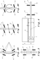
- the wheelbase E of the machine 1 is 30 to 50% larger than on the known machines of the state of the art as described in the disclosure of the invention. It is made possible for the center of gravity of the machine 1 to be and remain in a space P between (or which overcomes) the wheels 41, 42 as illustrated in Figure 3 where the center of gravity is indicated by a cross, and this whatever the position of the tool 2 along the direction of extension d. This position, like other parameters (for example, the inclination of the arm 3), is in fact likely to unbalance the machine 1 given the weight of the tool 2 and the arm 3.
- the leveling of the concrete surfaces S is thus made simple and efficient for the operator, thanks to the orientability of the wheels 41, 42, their capacity to support and stabilize the machine 1 in all circumstances, the presence of the central computer module 8 which makes it possible to control the movement of the machine 1 and to regulate different parameters of its operation.
Landscapes
- Engineering & Computer Science (AREA)
- Architecture (AREA)
- Civil Engineering (AREA)
- Structural Engineering (AREA)
- On-Site Construction Work That Accompanies The Preparation And Application Of Concrete (AREA)
Claims (16)
- Maschine (1) zur Bearbeitung einer Betonoberfläche, umfassend:- ein Werkzeug (2) zur Behandlung einer Oberfläche aus Beton, das mechanisch mit einem Ende eines mechanischen Teleskoparms (3) gekoppelt ist, so dass das Werkzeug (2) über die Betonoberfläche in einer Ausfahrrichtung (d) des Arms (3) bewegbar ist;- ein hohles Fach für den Arm (3);- Räder (41, 42), die mit dem Fach gekoppelt und angeordnet sind, um die Maschine (1) zu bewegen;dadurch gekennzeichnet, dass:- das Fach in einem Fahrgestell (5) der Maschine (1) ausgebildet ist, der sich hauptsächlich entlang der Ausfahrrichtung (d) erstreckt;- das Fahrgestell (5) zwei Endabschnitte (51, 52) umfasst, an denen jeweils mindestens eine Achse (61, 62) befestigt ist, die sich quer zur Ausfahrrichtung (d) erstreckt und mindestens eines der Räder (41, 42) trägt;- die Räder (41, 42) ausrichtbar und angepasst sind, um die Maschine (1) für jede Position des Werkzeugs (2) entlang der Ausfahrrichtung (d) zu tragen.
- Maschine (1) nach Anspruch 1, die einen in der Ausfahrrichtung (d) gemessenen Radstand (E) aufweist, der zwischen 35% und 65% einer in der Ausfahrrichtung (d) gemessenen maximalen Ausfahrlänge des Arms umfasst.
- Maschine (1) nach Anspruch 1 oder 2, wobei jede Achse (61, 62) umfasst:- einen axialen Teil (611, 621), der sich vom Fahrgestell (5) aus hauptsächlich quer zur Ausfahrrichtung (d) erstreckt;- zwei Schenkel (612, 622), von denen jedes umfasst:- ein oberes Ende (613, 623), das mechanisch mit einem Ende des axialen Teils (611, 621) über Drehmittel (7) gekoppelt ist, die angeordnet sind, um eine relative Drehung zwischen dem axialen Teil (611, 621) und dem Schenkel (612, 622) zu ermöglichen,- ein unteres Ende (614, 624), das im Bereich einer Nabe (43) eines der Räder (41, 42) befestigt ist.
- Maschine (1) nach Anspruch 3, wobei die Drehmittel (7) einen Drehmotor umfassen, der mechanisch mit einem Drehkranz gekoppelt ist.
- Maschine (1) nach Anspruch 3 oder 4, wobei jeder Schenkel (612, 622) bogenförmig ist, wobei die oberen (613, 623) und unteren (614, 624) Enden in einer Richtung orthogonal zur Ausfahrrichtung (d) ausgerichtet sind.
- Maschine (1) nach einem der vorstehenden Ansprüche, wobei mindestens eine der Achsen (62) Hebemittel umfasst, die angeordnet sind, um eine Veränderung eines Abstands zwischen dem Fahrgestell (5) und dem mindestens einen Rad (42), das von der Achse (62) getragen wird, zu ermöglichen.
- Maschine (1) nach Anspruch 6, wenn abhängig von einem der Ansprüche 3 bis 5, wobei jeder Schenkel (622) der Achse (62) eine Schwenkverbindung (625) umfasst, um die sich zwei Teile des Schenkels (622) gelenkig bewegen, wobei die Hebemittel einen Hydraulikzylinder umfassen, der im Bereich der Schwenkverbindung (625) angeordnet oder mit dieser gekoppelt ist.
- Maschine (1) nach einem der vorstehenden Ansprüche, wobei jedes Rad (41, 42) eine Nabe (43) umfasst, innerhalb derer ein Elektromotor zum Vorwärtsbewegen des Rads (41, 42) angeordnet ist.
- Maschine (1) nach einem der vorstehenden Ansprüche, umfassend eine elektrische Stromversorgung, die mit mindestens einem Elektromotor und einem Hydrauliksystem gekoppelt ist, um Funktionalitäten der Maschine (1) mit Strom zu versorgen, wobei diese jede Bewegung der Räder (41, 42), des Arms (3) und des Werkzeugs (2) umfassen.
- Maschine (1) nach einem der vorstehenden Ansprüche, umfassend einen im Fahrgestell (5) angeordneten Elektromotor zum Bewegen des Arms (3) über einen im Bereich des Elektromotors im Eingriff stehenden, vorzugsweise gezahnten, Riemen.
- Maschine (1) nach einem der vorstehenden Ansprüche, wobei das Werkzeug (2) mechanisch mit dem Ende des Arms (3) über eine Werkzeughalterstruktur (21) gekoppelt ist, die an dem Ende des Arms (3) auf beiden Seiten befestigt ist, von der zwei Hubzylinder (22) angeordnet sind, die das Werkzeug (2) tragen, um eine Hubbewegung desselben zu ändern, wobei jeder Hubzylinder (22) mit einem Positionssensor (23) ausgestattet ist.
- Maschine (1) nach Anspruch 11, wenn abhängig von Anspruch 10, wobei die Maschine (1) weiter einen Drehungssensor des Zahnriemens, der im Bereich desselben angeordnet ist, und ein zentrales Computermodul (8) umfasst, das elektrisch, elektronisch und/oder elektromechanisch mit dem Elektromotor und den Positions- (23) und Drehungssensoren gekoppelt und konfiguriert ist zum
Regulieren einer Geschwindigkeit der Bewegung des Arms (3) in einer geschlossenen Schleife auf der Grundlage von Daten, die von den Positions- (23) und Drehungssensoren gemessen werden. - Maschine (1) nach Anspruch 11, wobei die Maschine ein zentrales Computermodul (8) umfasst, das elektrisch, elektronisch und/oder elektromechanisch mit den Hubzylindern (22) und den Positionssensoren (23) gekoppelt ist,
und konfiguriert ist, um den Hub des Werkzeugs (2) in einer geschlossenen Schleife auf der Grundlage von Daten über die Fließfähigkeit des Betons und von durch die Positionssensoren (23) gemessenen Daten zu regulieren. - Maschine nach einem der vorstehenden Ansprüche, die keine stabilisierenden Füße aufweist.
- Verfahren zur Behandlung einer Folge von ähnlichen Betonoberflächen (S), die entlang einer Führungsrichtung (g) ausgerichtet sind, mittels einer Maschine (1) nach einem der Ansprüche 1 bis 11, wobei die Maschine (1) weiter mindestens einen Drehsensor umfasst, der im Bereich von mindestens einem der Räder (41, 42) angeordnet ist, um einen von diesem Rad (41, 42) zurückgelegten Weg zu messen, wobei das Verfahren die folgenden Schritte umfasst:(0) Positionieren der Maschine (1) gegenüber der ersten in der Folge zu behandelnden Betonoberfläche (S), so dass die Ausfahrrichtung (d) die Betonoberfläche (S) überwindet, wobei die Räder (41, 42) der Maschine in der Führungsrichtung (g) ausgerichtet sind;(i) Behandeln der Betonoberfläche (S) mit Hilfe der Maschine (1);(ii) Bewegen der Maschine (1) um einen vorbestimmten Abstand (L-L'), so dass die Ausfahrrichtung (d) die nächste zu behandelnde Betonoberfläche (S) in der Folge überwindet, wobei diese einen Endabdeckstreifen (R) mit der in Schritt (i) behandelten Betonoberfläche (S) umfasst, der sich parallel zu der Ausfahrrichtung (d) erstreckt;(iii) Wiederholen der Schritte (i) und (ii);wobei Schritt (ii) mittels eines zentralen Computermoduls der Maschine (1), das elektronisch und/oder elektromechanisch mit den Rädern (41, 42) gekoppelt ist, und auf der Grundlage von Daten, die von dem mindestens einen Drehsensor empfangen werden, reguliert wird.
- Verfahren zur Herstellung einer Betonoberfläche, umfassend die Verwendung einer Maschine (1) nach einem der Ansprüche 1 bis 14 zur Behandlung der Betonoberfläche.
Priority Applications (1)
| Application Number | Priority Date | Filing Date | Title |
|---|---|---|---|
| EP22193046.4A EP4332303B1 (de) | 2022-08-31 | 2022-08-31 | Maschine zur bearbeitung einer betonoberfläche, verfahren zur bearbeitung einer folge von betonoberflächen und verfahren zur herstellung einer betonoberfläche |
Applications Claiming Priority (1)
| Application Number | Priority Date | Filing Date | Title |
|---|---|---|---|
| EP22193046.4A EP4332303B1 (de) | 2022-08-31 | 2022-08-31 | Maschine zur bearbeitung einer betonoberfläche, verfahren zur bearbeitung einer folge von betonoberflächen und verfahren zur herstellung einer betonoberfläche |
Publications (3)
| Publication Number | Publication Date |
|---|---|
| EP4332303A1 EP4332303A1 (de) | 2024-03-06 |
| EP4332303C0 EP4332303C0 (de) | 2025-05-21 |
| EP4332303B1 true EP4332303B1 (de) | 2025-05-21 |
Family
ID=83232496
Family Applications (1)
| Application Number | Title | Priority Date | Filing Date |
|---|---|---|---|
| EP22193046.4A Active EP4332303B1 (de) | 2022-08-31 | 2022-08-31 | Maschine zur bearbeitung einer betonoberfläche, verfahren zur bearbeitung einer folge von betonoberflächen und verfahren zur herstellung einer betonoberfläche |
Country Status (1)
| Country | Link |
|---|---|
| EP (1) | EP4332303B1 (de) |
Families Citing this family (1)
| Publication number | Priority date | Publication date | Assignee | Title |
|---|---|---|---|---|
| CN120537433B (zh) * | 2025-06-10 | 2025-10-10 | 河北中铸爱军建设集团股份有限公司 | 一种型钢混凝土结构的固定定位装置 |
Family Cites Families (4)
| Publication number | Priority date | Publication date | Assignee | Title |
|---|---|---|---|---|
| US4655633A (en) * | 1985-09-23 | 1987-04-07 | David W. Somero | Screeding apparatus and method |
| US20070116520A1 (en) * | 2005-11-18 | 2007-05-24 | Quenzi Philip J | Vibrating device for screeding machine |
| US10895045B2 (en) | 2017-12-18 | 2021-01-19 | Somero Enterprises, Inc. | Concrete screeding machine with column block control using gyro sensor |
| US11560727B2 (en) * | 2018-10-08 | 2023-01-24 | Ligchine International Corporation | Apparatus for screeding concrete |
-
2022
- 2022-08-31 EP EP22193046.4A patent/EP4332303B1/de active Active
Also Published As
| Publication number | Publication date |
|---|---|
| EP4332303A1 (de) | 2024-03-06 |
| EP4332303C0 (de) | 2025-05-21 |
Similar Documents
| Publication | Publication Date | Title |
|---|---|---|
| EP2537684B1 (de) | Halbachse und Fahrzeug, das mit mindestens einer solchen Halbachse ausgestattet ist | |
| EP1044130B1 (de) | Kreiselstabilisiertes gerät, insbesondere ein zweibeiniger roboter | |
| EP3522845B1 (de) | Mobilitätsassistenzfahrzeug zur überquerung von hindernissen | |
| EP2374635B1 (de) | Achssystem, Achsmodul, das mindestens ein solches Achssytem umfasst und Fahrzeug, das mindestens ein solches Modul umfasst | |
| EP1118531A1 (de) | Fahrzeug für unebenes Gelände | |
| EP4332303B1 (de) | Maschine zur bearbeitung einer betonoberfläche, verfahren zur bearbeitung einer folge von betonoberflächen und verfahren zur herstellung einer betonoberfläche | |
| WO2006111825A1 (fr) | Procede de construction de murs maconnes et dispositif mettant en oeuvre ledit procede | |
| CA3023784A1 (fr) | Engin roulant, notamment pour la depose au sol de materiaux en vrac | |
| EP4049936A1 (de) | System mit einem beweglichen schlitten und verfahren zur anwendung eines solchen systems mit beweglichem schlitten | |
| FR3010466A1 (fr) | Dispositif de renvoi d'angle a piece de couplage cooperant avec une barre de commande, pour un equipement transformable | |
| FR3126958A1 (fr) | Véhicule terrestre compact à haute mobilité | |
| EP4294597A1 (de) | Transportable kompakte korrekturvorrichtung, insbesondere zum polieren von kalanderzylindern | |
| FR3132444A1 (fr) | Dispositif d’agrippement d’un tronçon de garnissage | |
| FR2936212A1 (fr) | Dispositif de transport a carrossage variable pour tunnel | |
| FR3092791A1 (fr) | Système de suspension bidirectionnelle pour essieu à roues indépendantes d’un véhicule | |
| FR3018748A1 (fr) | Motocycle a un seul train de roues | |
| EP0612542B1 (de) | In drei Richtungen periodische Bewegungen reproduzierende Plattform, mit einer bevorzugten Richtung | |
| FR3122226A1 (fr) | Vireur de mise en rotation d'une virole, ainsi que procédé de mise en rotation d'une virole | |
| US12516529B2 (en) | Machine for treating a concrete surface | |
| EP4474577A1 (de) | Planierer | |
| FR3063035A1 (fr) | Exosquelette ameliore pour assistance aux efforts horizontaux. | |
| WO2005024155A1 (fr) | Echafaudage mobile a echelles verticales | |
| EP1473411A1 (de) | Vorrichtung zur seitlichen Versetzung von einer Fahrbahntrenneinrichtung | |
| FR2848200A1 (fr) | Dispositif de manutention d'une charge | |
| EP4534759A1 (de) | Robotisches mähsystem für den vegetationsbereich eines schienengebundenen gleises, wartungsfahrzeug und verfahren |
Legal Events
| Date | Code | Title | Description |
|---|---|---|---|
| PUAI | Public reference made under article 153(3) epc to a published international application that has entered the european phase |
Free format text: ORIGINAL CODE: 0009012 |
|
| STAA | Information on the status of an ep patent application or granted ep patent |
Free format text: STATUS: THE APPLICATION HAS BEEN PUBLISHED |
|
| AK | Designated contracting states |
Kind code of ref document: A1 Designated state(s): AL AT BE BG CH CY CZ DE DK EE ES FI FR GB GR HR HU IE IS IT LI LT LU LV MC MK MT NL NO PL PT RO RS SE SI SK SM TR |
|
| STAA | Information on the status of an ep patent application or granted ep patent |
Free format text: STATUS: REQUEST FOR EXAMINATION WAS MADE |
|
| 17P | Request for examination filed |
Effective date: 20240906 |
|
| RBV | Designated contracting states (corrected) |
Designated state(s): AL AT BE BG CH CY CZ DE DK EE ES FI FR GB GR HR HU IE IS IT LI LT LU LV MC MK MT NL NO PL PT RO RS SE SI SK SM TR |
|
| GRAP | Despatch of communication of intention to grant a patent |
Free format text: ORIGINAL CODE: EPIDOSNIGR1 |
|
| STAA | Information on the status of an ep patent application or granted ep patent |
Free format text: STATUS: GRANT OF PATENT IS INTENDED |
|
| INTG | Intention to grant announced |
Effective date: 20241216 |
|
| GRAS | Grant fee paid |
Free format text: ORIGINAL CODE: EPIDOSNIGR3 |
|
| GRAA | (expected) grant |
Free format text: ORIGINAL CODE: 0009210 |
|
| STAA | Information on the status of an ep patent application or granted ep patent |
Free format text: STATUS: THE PATENT HAS BEEN GRANTED |
|
| AK | Designated contracting states |
Kind code of ref document: B1 Designated state(s): AL AT BE BG CH CY CZ DE DK EE ES FI FR GB GR HR HU IE IS IT LI LT LU LV MC MK MT NL NO PL PT RO RS SE SI SK SM TR |
|
| REG | Reference to a national code |
Ref country code: GB Ref legal event code: FG4D Free format text: NOT ENGLISH |
|
| REG | Reference to a national code |
Ref country code: CH Ref legal event code: EP |
|
| REG | Reference to a national code |
Ref country code: DE Ref legal event code: R096 Ref document number: 602022014881 Country of ref document: DE |
|
| REG | Reference to a national code |
Ref country code: IE Ref legal event code: FG4D Free format text: LANGUAGE OF EP DOCUMENT: FRENCH |
|
| U01 | Request for unitary effect filed |
Effective date: 20250623 |
|
| U07 | Unitary effect registered |
Designated state(s): AT BE BG DE DK EE FI FR IT LT LU LV MT NL PT RO SE SI Effective date: 20250701 |
|
| U20 | Renewal fee for the european patent with unitary effect paid |
Year of fee payment: 4 Effective date: 20250829 |
|
| PG25 | Lapsed in a contracting state [announced via postgrant information from national office to epo] |
Ref country code: ES Free format text: LAPSE BECAUSE OF FAILURE TO SUBMIT A TRANSLATION OF THE DESCRIPTION OR TO PAY THE FEE WITHIN THE PRESCRIBED TIME-LIMIT Effective date: 20250521 |
|
| PG25 | Lapsed in a contracting state [announced via postgrant information from national office to epo] |
Ref country code: NO Free format text: LAPSE BECAUSE OF FAILURE TO SUBMIT A TRANSLATION OF THE DESCRIPTION OR TO PAY THE FEE WITHIN THE PRESCRIBED TIME-LIMIT Effective date: 20250821 Ref country code: GR Free format text: LAPSE BECAUSE OF FAILURE TO SUBMIT A TRANSLATION OF THE DESCRIPTION OR TO PAY THE FEE WITHIN THE PRESCRIBED TIME-LIMIT Effective date: 20250822 |
|
| PG25 | Lapsed in a contracting state [announced via postgrant information from national office to epo] |
Ref country code: PL Free format text: LAPSE BECAUSE OF FAILURE TO SUBMIT A TRANSLATION OF THE DESCRIPTION OR TO PAY THE FEE WITHIN THE PRESCRIBED TIME-LIMIT Effective date: 20250521 |
|
| PG25 | Lapsed in a contracting state [announced via postgrant information from national office to epo] |
Ref country code: HR Free format text: LAPSE BECAUSE OF FAILURE TO SUBMIT A TRANSLATION OF THE DESCRIPTION OR TO PAY THE FEE WITHIN THE PRESCRIBED TIME-LIMIT Effective date: 20250521 |
|
| PG25 | Lapsed in a contracting state [announced via postgrant information from national office to epo] |
Ref country code: RS Free format text: LAPSE BECAUSE OF FAILURE TO SUBMIT A TRANSLATION OF THE DESCRIPTION OR TO PAY THE FEE WITHIN THE PRESCRIBED TIME-LIMIT Effective date: 20250821 |
|
| PG25 | Lapsed in a contracting state [announced via postgrant information from national office to epo] |
Ref country code: IS Free format text: LAPSE BECAUSE OF FAILURE TO SUBMIT A TRANSLATION OF THE DESCRIPTION OR TO PAY THE FEE WITHIN THE PRESCRIBED TIME-LIMIT Effective date: 20250921 |
|
| PG25 | Lapsed in a contracting state [announced via postgrant information from national office to epo] |
Ref country code: SM Free format text: LAPSE BECAUSE OF FAILURE TO SUBMIT A TRANSLATION OF THE DESCRIPTION OR TO PAY THE FEE WITHIN THE PRESCRIBED TIME-LIMIT Effective date: 20250521 |
|
| PG25 | Lapsed in a contracting state [announced via postgrant information from national office to epo] |
Ref country code: CZ Free format text: LAPSE BECAUSE OF FAILURE TO SUBMIT A TRANSLATION OF THE DESCRIPTION OR TO PAY THE FEE WITHIN THE PRESCRIBED TIME-LIMIT Effective date: 20250521 |
|
| PG25 | Lapsed in a contracting state [announced via postgrant information from national office to epo] |
Ref country code: SK Free format text: LAPSE BECAUSE OF FAILURE TO SUBMIT A TRANSLATION OF THE DESCRIPTION OR TO PAY THE FEE WITHIN THE PRESCRIBED TIME-LIMIT Effective date: 20250521 |