EP4332294A1 - A laundry washer and/or dryer comprising a locking member - Google Patents
A laundry washer and/or dryer comprising a locking member Download PDFInfo
- Publication number
- EP4332294A1 EP4332294A1 EP23188651.6A EP23188651A EP4332294A1 EP 4332294 A1 EP4332294 A1 EP 4332294A1 EP 23188651 A EP23188651 A EP 23188651A EP 4332294 A1 EP4332294 A1 EP 4332294A1
- Authority
- EP
- European Patent Office
- Prior art keywords
- opening
- front wall
- connection
- connection member
- dryer
- Prior art date
- Legal status (The legal status is an assumption and is not a legal conclusion. Google has not performed a legal analysis and makes no representation as to the accuracy of the status listed.)
- Granted
Links
Images


Classifications
-
- D—TEXTILES; PAPER
- D06—TREATMENT OF TEXTILES OR THE LIKE; LAUNDERING; FLEXIBLE MATERIALS NOT OTHERWISE PROVIDED FOR
- D06F—LAUNDERING, DRYING, IRONING, PRESSING OR FOLDING TEXTILE ARTICLES
- D06F39/00—Details of washing machines not specific to a single type of machines covered by groups D06F9/00 - D06F27/00
- D06F39/12—Casings; Tubs
- D06F39/14—Doors or covers; Securing means therefor
-
- D—TEXTILES; PAPER
- D06—TREATMENT OF TEXTILES OR THE LIKE; LAUNDERING; FLEXIBLE MATERIALS NOT OTHERWISE PROVIDED FOR
- D06F—LAUNDERING, DRYING, IRONING, PRESSING OR FOLDING TEXTILE ARTICLES
- D06F37/00—Details specific to washing machines covered by groups D06F21/00 - D06F25/00
- D06F37/26—Casings; Tubs
- D06F37/28—Doors; Security means therefor
-
- D—TEXTILES; PAPER
- D06—TREATMENT OF TEXTILES OR THE LIKE; LAUNDERING; FLEXIBLE MATERIALS NOT OTHERWISE PROVIDED FOR
- D06F—LAUNDERING, DRYING, IRONING, PRESSING OR FOLDING TEXTILE ARTICLES
- D06F25/00—Washing machines with receptacles, e.g. perforated, having a rotary movement, e.g. oscillatory movement, the receptacle serving both for washing and for centrifugally separating water from the laundry and having further drying means, e.g. using hot air
Definitions
- the present invention relates to a laundry washer and/or dryer comprising a locking member which enables the door to be kept closed.
- the laundry to be washed or dried is loaded into the drum through a loading opening and the loading opening is closed by the door. Keeping the door in the closed position is ensured by a locking member.
- locking is realized by the placement of a lock latch disposed on the door into the lock body of the locking member provided on the front wall.
- the lock body is mounted on the front wall by being aligned with the opening on the front wall.
- the locking member is usually grouped to the front wall with connection members such as screws. Afterwards, usually a connection member is inserted into the front wall by means of screws or nails from the front of the front wall.
- the purpose of the connection member is to provide an aesthetic appearance for the user by preventing the user from seeing the locking member through the opening on the front wall.
- connection member and the connection member are visible to the user and an aesthetic appearance cannot be obtained.
- mounting the connection member and the locking member to the front wall separately with screw or nail structures causes an additional assembly process in production, thus causing serious time losses and cost increase in production.
- the rails which are provided on the connection member and which extend in the vertical axis are attached to the slides on the lock by being slid in the vertical axis such that the connection member and the lock are grouped to the front wall at the same time.
- the front wall There is a limited space on the front wall for the fastening movement of the connection member in the vertical axis. Therefore, the size of the connection member must be small. This increases the possibility of encountering various safety problems.
- a washer/dryer comprising a lock group wherein the lock group is snap-fittingly mounted by being rotated and slid after being inserted through the front wall from a single side.
- the aim of the present invention is the realization of a laundry washer and/or dryer comprising a cost-efficient locking member with increased safety which provides ease of assembly.
- the laundry washer and/or dryer realized in order to attain the aim of the present invention, explicated in the first claim and the respective claims thereof, comprises a body; a drum which is provided in the body and wherein the laundry to be washed and/or dried is placed; a front wall which is provided on the body and which has a loading opening allowing the laundry to be placed in the drum; a door which covers the loading opening; a lock latch which is provided on the door; an opening which is provided on the front wall so as to be adjacent to the loading opening; a locking member which is inserted into the opening from the rear side of the front wall facing the drum, which enables the door to remain closed throughout the washing/drying process and which has a lock body remaining behind the front wall and an extension extending to the front of the front wall; a rail on each side of the extension; a connection member which has two slides entering the rails when slid in a vertical engagement direction and which is attached to the locking member so as to move together with the locking member as the slides are fitted into the rails; at least one
- the locking member is mounted in a quick and easy manner, and mounting safety is increased by mounting the connection member onto the front wall by being slid in the engagement direction and in the fixing direction perpendicular to the engagement direction together with the locking member.
- This embodiment is also advantageous in that mounting tolerances are increased and thus faulty operation is prevented by means of ensuring the centering in two axes.
- connection foot on the connection foot, at least one protrusion is provided, which extends from the horizontal and vertical guiding openings towards the rear of the front wall.
- the protrusions abut against the rear of the front wall when the connection foot is in the horizontal guiding opening.
- the horizontal guiding opening narrows in the fixing direction.
- the connection member which slidably moves in the horizontal guiding opening is pressed into the horizontal guiding opening.
- connection member on the connection member, at least one claw is provided, which enables the connection member to be fixed to the front wall in the horizontal axis by passing through the opening to the rear side of the front wall during the movement of the connection member in the fixing direction.
- connection member and the locking member are attached to the front wall so as not to move in the horizontal axis and the mounting safety is increased.
- connection foot on the vertical guiding opening, at least one stopper edge is provided, which limits the movement of the connection foot in the vertical guiding opening by bearing against the connection foot.
- connection foot on the horizontal guiding opening, at least one limiting member is provided, which limits the movement of the connection foot in the horizontal guiding opening by bearing against the same.
- the connection foot is prevented from moving in the horizontal fixing direction while bearing against the limiting member, and the locking member is easily centered in the opening.
- the claws on the connection member flex and pass through the opening on the front wall so as to be locked onto the front wall.
- connection member covers the vertical guiding opening and the horizontal guiding opening on the front wall in a fixing position where the connection member is brought at the end of the movement in the fixing direction.
- connection of the connection member and the locking member to the front wall is achieved without the need for any additional assembly processes while increasing assembly safety in a cost-effective manner.
- the laundry washer and/or dryer (1) comprises a body (2); a drum (3) which is provided in the body (2) and wherein the laundry to be washed and/or dried is placed; a front wall (5) which is provided on the body (2) and which has a loading opening (4) allowing the laundry to be placed in the drum (3); a door (6) which covers the loading opening (4); a lock latch (7) which is provided on the door (6); an opening (8) which is provided on the front wall (5); a locking member (11) which is inserted into the opening and which has an extension (9) passing through the opening (8) and remaining in front of the front wall (5) and a lock body (10) remaining at the rear side of the opening (8); a rail (12) which is provided on each side of the extension (9); and a connection member (15) having at least two slides (14) entering the rails when slid in a vertical engagement direction (Y) and enabling the connection member (15) to be attached onto the locking member (11).
- the laundry washer and/or dryer (1) is a washing machine, a laundry dryer or a laundry washing/drying machine.
- the locking member (11) When the locking member (11) is placed in the opening (8) from the side of the opening (8) facing the inside of the drum (3), the extension (9) provided on the locking member (11) passes through the opening (8) and reaches to the front side of the front wall (5).
- the slides (14) provided on the connection member (15) are inserted into the rails (12) located on both sides of the extension (9). Then, when the connection member (15) is moved in the engagement direction (Y), the slides (14) are slidably moved in the rails (12).
- the connection member (15) and the locking member (11) engage with each other.
- the laundry washer and/or dryer (1) of the present invention comprises at least one connection foot (16) which is provided on the connection member (15); at least one vertical guiding opening (17) which extends on the front wall (5) in the vertical axis and wherein the connection foot (16) slidably moves during the movement of the connection member (15) in the engagement direction (Y); and at least one horizontal guiding opening (18) which extends on the front wall (5) in the horizontal axis, which joins with the vertical guiding opening (17) and wherein the connection foot (16) slidably moves as the connection member (15) and the locking member (11) attached thereon are pushed in a fixing direction (X) perpendicular to the engagement direction (Y).
- the connection member (15) has at least one connection foot (16).
- the vertical guiding openings (17) are provided on the front wall (5) such that the connection feet (16) provided on the connection member (15) can move in the vertical direction with the movement of the connection member (15) in the engagement direction (Y).
- the connection feet (16) By moving the connecting member (15) in the engagement direction (Y), the connection feet (16) slidably move in the vertical guiding opening (17).
- the horizontal guiding openings (18) are provided, which join with the vertical guiding openings (17) on the front wall (5) and which guide the movement of the connection member (15) in a fixing direction (X) almost perpendicular to the movement thereof in the vertical direction in the engagement direction (Y).
- connection feet (16) slide in the vertical and horizontal guiding openings (17, 18) so as to guide the movement of the connection member (15) in both vertical and horizontal axes. Consequently, together with the connection member (15), the locking member (11) is placed in the opening (8) by being moved in the fixing direction (X) perpendicular to the engagement direction (Y), and fast and safe assembly of the connection member (15) and the locking member (11) group is ensured.
- the technical problem of the small size of the connection member (15) due to the limited space on the front wall (5) for the movement of the connection member (15) in the vertical axis in the engagement direction (Y), and thus the failure to provide sufficient strength, is eliminated.
- connection foot (16) on the connection foot (16), at least one protrusion (19) is provided, which bears against the front wall (5) when the connection foot (16) is in the horizontal guiding opening (18).
- the connection foot (16) is moved in the engagement direction (Y) to be connected to the locking member (11)
- the connection foot (16) is fitted into the horizontal guiding opening (18).
- the protrusion (19) provided on the connection foot (16) and extending to the rear of the front wall (5) acts as a hook.
- the connection member (15) and the locking member (11) which are connected to each other at the end of the movement of the connection member (15) in the engagement direction (Y) are connected to the front wall (5) so as not to be pulled out through the opening (8).
- a horizontal guiding opening (18) has a form which narrows down in the fixing direction (X).
- the connection foot (16) close-fits into the horizontal guiding opening (18) and limits the movement of the connection member (15) in the horizontal axis.
- the connection member (15) and the locking member (11) are enabled to be mounted on the front wall (5) more securely.
- connection member (15) on the connection member (15), at least one claw (13) is provided, which passes through the opening (8) with the movement of the connection member (15) in the fixing direction (X) and extends behind the front wall (5).
- the claws (13) which can be locked by flexing engage with the front wall (5) at the end of the movement of the connection member (15) in the fixing direction (X), and enable the connection member (15) to be fixed on the front wall (5) in the horizontal axis.
- the width of the opening (8) in the fixing direction (X) is slightly larger than the width of the extension (9) in the fixing direction (X).
- At least one stopper edge (20) is provided, which limits the movement of the connection foot (16) in the vertical guiding opening (17) by bearing against the connection foot (16).
- connection foot (16) on the horizontal guiding opening (18), at least one limiting member (21) is provided, which limits the movement of the connection foot (16) in the horizontal guiding opening (18) by bearing against the connection foot (16).
- the connection foot (16) bears against the limiting member (21).
- the claws (13) provided on the connection member (15) pass through the opening (8) and are locked onto the front wall (5).
- the movement of the connection member (15) both in the fixing direction (X) and in the direction opposite to the fixing direction (X) is prevented.
- connection member (15) at least partially covers the horizontal guiding opening (17) and/or the vertical guiding opening (18).
- the connection member (15) is moved in the fixing direction (X) until the connection feet (16) provided on the connection member (15) bear against the limiting member (21) and the claws (13) provided on the connection member (15) pass through the opening (8) and engage with the front wall (5).
- the connection member (15) partially covers the front wall (5) so as to cover the vertical guiding opening (17) and the horizontal guiding opening (18) on the front wall (5).
- an aesthetic appearance is provided for the user.
- a laundry washer and/or dryer (1) is realized, with improved aesthetic appearance and safety in a cost-effective manner, comprising a locking member (11) which is easily mounted onto the front wall (5).
Landscapes
- Engineering & Computer Science (AREA)
- Textile Engineering (AREA)
- Detail Structures Of Washing Machines And Dryers (AREA)
Abstract
Description
- The present invention relates to a laundry washer and/or dryer comprising a locking member which enables the door to be kept closed.
- In laundry washer and/or dryers, the laundry to be washed or dried is loaded into the drum through a loading opening and the loading opening is closed by the door. Keeping the door in the closed position is ensured by a locking member. Generally, locking is realized by the placement of a lock latch disposed on the door into the lock body of the locking member provided on the front wall. The lock body is mounted on the front wall by being aligned with the opening on the front wall. The locking member is usually grouped to the front wall with connection members such as screws. Afterwards, usually a connection member is inserted into the front wall by means of screws or nails from the front of the front wall. The purpose of the connection member is to provide an aesthetic appearance for the user by preventing the user from seeing the locking member through the opening on the front wall. However, the screws which enable the lock and the connection member to be grouped on the front wall are visible to the user and an aesthetic appearance cannot be obtained. Moreover, mounting the connection member and the locking member to the front wall separately with screw or nail structures causes an additional assembly process in production, thus causing serious time losses and cost increase in production. As a solution to this technical problem, in one of the state of the art embodiments, the rails which are provided on the connection member and which extend in the vertical axis are attached to the slides on the lock by being slid in the vertical axis such that the connection member and the lock are grouped to the front wall at the same time. There is a limited space on the front wall for the fastening movement of the connection member in the vertical axis. Therefore, the size of the connection member must be small. This increases the possibility of encountering various safety problems.
- In the state of the art European Patent Application No.
EP2655724 , a washer/dryer is disclosed, wherein the connection member is attached by being slid on the lock in a single axis. However, this embodiment is disadvantageous in that sufficient mounting safety cannot be provided since the connection member is connected in a single axis, the size of the connection member is small and the locking is performed in a single axis. - In the state of the art European Patent Application No.
EP1681386 , a washer/dryer is disclosed, comprising a lock group wherein the lock group is snap-fittingly mounted by being rotated and slid after being inserted through the front wall from a single side. - The aim of the present invention is the realization of a laundry washer and/or dryer comprising a cost-efficient locking member with increased safety which provides ease of assembly.
- The laundry washer and/or dryer realized in order to attain the aim of the present invention, explicated in the first claim and the respective claims thereof, comprises a body; a drum which is provided in the body and wherein the laundry to be washed and/or dried is placed; a front wall which is provided on the body and which has a loading opening allowing the laundry to be placed in the drum; a door which covers the loading opening; a lock latch which is provided on the door; an opening which is provided on the front wall so as to be adjacent to the loading opening; a locking member which is inserted into the opening from the rear side of the front wall facing the drum, which enables the door to remain closed throughout the washing/drying process and which has a lock body remaining behind the front wall and an extension extending to the front of the front wall; a rail on each side of the extension; a connection member which has two slides entering the rails when slid in a vertical engagement direction and which is attached to the locking member so as to move together with the locking member as the slides are fitted into the rails; at least one connection foot which is provided on the connection member; at least one vertical guiding opening which extends on the front wall in the engagement direction, which guides the movement of the connection member in the engagement direction and wherein the connection foot moves during the movement of the connection member in the engagement direction; and at least one horizontal guiding opening which is provided on the front wall, which extends in the horizontal axis, which joins with the vertical guiding opening, which guides the movement of the locking member and the connection member in the fixing direction and wherein the connection foot slidably moves as moved in a fixing direction perpendicular to the engagement direction together with the locking member whereon the connection member is attached. Thus, the locking member is mounted in a quick and easy manner, and mounting safety is increased by mounting the connection member onto the front wall by being slid in the engagement direction and in the fixing direction perpendicular to the engagement direction together with the locking member. This embodiment is also advantageous in that mounting tolerances are increased and thus faulty operation is prevented by means of ensuring the centering in two axes.
- In an embodiment of the present invention, on the connection foot, at least one protrusion is provided, which extends from the horizontal and vertical guiding openings towards the rear of the front wall. The protrusions abut against the rear of the front wall when the connection foot is in the horizontal guiding opening. Thus, the connection member and the locking member which are connected to each other are attached to the front wall so as not to be pulled out from the front wall.
- In another embodiment of the present invention, the horizontal guiding opening narrows in the fixing direction. Thus, the connection member which slidably moves in the horizontal guiding opening is pressed into the horizontal guiding opening.
- In another embodiment of the present invention, on the connection member, at least one claw is provided, which enables the connection member to be fixed to the front wall in the horizontal axis by passing through the opening to the rear side of the front wall during the movement of the connection member in the fixing direction. Thus, the connection member and the locking member are attached to the front wall so as not to move in the horizontal axis and the mounting safety is increased.
- In another embodiment of the present invention, on the vertical guiding opening, at least one stopper edge is provided, which limits the movement of the connection foot in the vertical guiding opening by bearing against the connection foot. Thus, after the slides on the connection member are inserted into the rails on the locking member in the vertical axis, the connection member is prevented from moving more in the vertical axis and the slide is prevented from leaving the rail.
- In another embodiment of the present invention, on the horizontal guiding opening, at least one limiting member is provided, which limits the movement of the connection foot in the horizontal guiding opening by bearing against the same. Thus, the connection foot is prevented from moving in the horizontal fixing direction while bearing against the limiting member, and the locking member is easily centered in the opening. Moreover, when the connection foot contacts the limiting member, the claws on the connection member flex and pass through the opening on the front wall so as to be locked onto the front wall.
- In another embodiment of the present invention, the connection member covers the vertical guiding opening and the horizontal guiding opening on the front wall in a fixing position where the connection member is brought at the end of the movement in the fixing direction. Thus, by means of the connection member, the user is prevented from seeing the openings on the front wall and a more aesthetic appearance is provided for the user.
- By means of the present invention, the connection of the connection member and the locking member to the front wall is achieved without the need for any additional assembly processes while increasing assembly safety in a cost-effective manner.
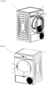
- The laundry washer and/or dryer realized in order to attain the aim of the present invention is illustrated in the attached figures, where:
-
Figure 1 - is the perspective view of the laundry washer and/or dryer related to an embodiment of the present invention. -
Figure 2 - is the perspective view of the body of the laundry washer and/or dryer related to another embodiment of the present invention. -
Figure 3 - is the front partial view of the front wall of the laundry washer and/or dryer related to another embodiment of the present invention. -
Figure 4 - is the front view of the connection member before the slides are inserted into the rails related to another embodiment of the present invention. -
Figure 5 - is the rear view of the connection member and the locking member before the slides are inserted into the rails related to another embodiment of the present invention. -
Figure 6 - is the view of the connection member and the locking member when the slides are inserted into the rails by sliding the connection member in the engagement direction related to another embodiment of the present invention. -
Figure 7 - is the view showing the connection member and the locking member being pushed in the fixing direction related to another embodiment of the present invention. -
Figure 8 - is the cross-sectional view where the connection member and the locking member are connected to the front wall related to another embodiment of the present invention. -
Figure 9 - is the front view where the connection member and the locking member are connected to the front wall related to another embodiment of the present invention. - The elements illustrated in the figures are numbered as follows:
- 1- Laundry washer and/or dryer
- 2- Body
- 3- Drum
- 4- Loading opening
- 5- Front wall
- 6- Door
- 7- Lock latch
- 8- Opening
- 9- Extension
- 10- Lock body
- 11- Locking member
- 12- Rail
- 13- Claw
- 14- Slide
- 15- Connection member
- 16- Connection foot
- 17- Vertical guiding opening
- 18- Horizontal guiding opening
- 19- Protrusion
- 20- Stopper edge
- 21- Limiting member
- X: Fixing direction
- Y: Engagement direction
- The laundry washer and/or dryer (1) comprises a body (2); a drum (3) which is provided in the body (2) and wherein the laundry to be washed and/or dried is placed; a front wall (5) which is provided on the body (2) and which has a loading opening (4) allowing the laundry to be placed in the drum (3); a door (6) which covers the loading opening (4); a lock latch (7) which is provided on the door (6); an opening (8) which is provided on the front wall (5); a locking member (11) which is inserted into the opening and which has an extension (9) passing through the opening (8) and remaining in front of the front wall (5) and a lock body (10) remaining at the rear side of the opening (8); a rail (12) which is provided on each side of the extension (9); and a connection member (15) having at least two slides (14) entering the rails when slid in a vertical engagement direction (Y) and enabling the connection member (15) to be attached onto the locking member (11). The laundry washer and/or dryer (1) is a washing machine, a laundry dryer or a laundry washing/drying machine. When the locking member (11) is placed in the opening (8) from the side of the opening (8) facing the inside of the drum (3), the extension (9) provided on the locking member (11) passes through the opening (8) and reaches to the front side of the front wall (5). First, the slides (14) provided on the connection member (15) are inserted into the rails (12) located on both sides of the extension (9). Then, when the connection member (15) is moved in the engagement direction (Y), the slides (14) are slidably moved in the rails (12). Thus, the connection member (15) and the locking member (11) engage with each other.
- The laundry washer and/or dryer (1) of the present invention comprises at least one connection foot (16) which is provided on the connection member (15); at least one vertical guiding opening (17) which extends on the front wall (5) in the vertical axis and wherein the connection foot (16) slidably moves during the movement of the connection member (15) in the engagement direction (Y); and at least one horizontal guiding opening (18) which extends on the front wall (5) in the horizontal axis, which joins with the vertical guiding opening (17) and wherein the connection foot (16) slidably moves as the connection member (15) and the locking member (11) attached thereon are pushed in a fixing direction (X) perpendicular to the engagement direction (Y). The connection member (15) has at least one connection foot (16). The vertical guiding openings (17) are provided on the front wall (5) such that the connection feet (16) provided on the connection member (15) can move in the vertical direction with the movement of the connection member (15) in the engagement direction (Y). By moving the connecting member (15) in the engagement direction (Y), the connection feet (16) slidably move in the vertical guiding opening (17). Thus, the movement of the connection member (15) in the engagement direction (Y) is guided. In order to move the connection member (15) together with the locking member (11) in the horizontal direction, the horizontal guiding openings (18) are provided, which join with the vertical guiding openings (17) on the front wall (5) and which guide the movement of the connection member (15) in a fixing direction (X) almost perpendicular to the movement thereof in the vertical direction in the engagement direction (Y). The horizontal guiding opening (18) join with the vertical guiding opening (17) and the horizontal guiding opening (18) and the vertical guiding opening (17) together form an almost L-shaped opening on the front wall (5). Thus, the connection feet (16) slide in the vertical and horizontal guiding openings (17, 18) so as to guide the movement of the connection member (15) in both vertical and horizontal axes. Consequently, together with the connection member (15), the locking member (11) is placed in the opening (8) by being moved in the fixing direction (X) perpendicular to the engagement direction (Y), and fast and safe assembly of the connection member (15) and the locking member (11) group is ensured. Thus, the technical problem of the small size of the connection member (15) due to the limited space on the front wall (5) for the movement of the connection member (15) in the vertical axis in the engagement direction (Y), and thus the failure to provide sufficient strength, is eliminated.
- In an embodiment of the present invention, on the connection foot (16), at least one protrusion (19) is provided, which bears against the front wall (5) when the connection foot (16) is in the horizontal guiding opening (18). As the connection member (15) is moved in the engagement direction (Y) to be connected to the locking member (11), the connection foot (16) is fitted into the horizontal guiding opening (18). When the connection foot (16) is in the horizontal guiding opening (18), the protrusion (19) provided on the connection foot (16) and extending to the rear of the front wall (5) acts as a hook. Thus, the connection member (15) and the locking member (11) which are connected to each other at the end of the movement of the connection member (15) in the engagement direction (Y) are connected to the front wall (5) so as not to be pulled out through the opening (8).
- In another embodiment of the present invention, a horizontal guiding opening (18) has a form which narrows down in the fixing direction (X). When the connection member (15) is pushed in the fixing direction (X), the connection foot (16) close-fits into the horizontal guiding opening (18) and limits the movement of the connection member (15) in the horizontal axis. Thus, the connection member (15) and the locking member (11) are enabled to be mounted on the front wall (5) more securely.
- In another embodiment of the present invention, on the connection member (15), at least one claw (13) is provided, which passes through the opening (8) with the movement of the connection member (15) in the fixing direction (X) and extends behind the front wall (5). The claws (13) which can be locked by flexing engage with the front wall (5) at the end of the movement of the connection member (15) in the fixing direction (X), and enable the connection member (15) to be fixed on the front wall (5) in the horizontal axis. The width of the opening (8) in the fixing direction (X) is slightly larger than the width of the extension (9) in the fixing direction (X). Thus, the connection member (15) and the locking member (11) are enabled to be connected to the front wall (5) in a secure manner.
- In another embodiment of the present invention, on the vertical guiding opening (17), at least one stopper edge (20) is provided, which limits the movement of the connection foot (16) in the vertical guiding opening (17) by bearing against the connection foot (16). Thus, when the slides (14) provided on the connection member (15) are inserted into the rails (12) provided on the locking member (11) in the engagement direction (Y), the connection foot (16) provided on the connection member (15) contacts the stopper edge (20) provided on the vertical guiding opening (17), and the movement of the connection member (15) in the vertical axis is terminated.
- In another embodiment of the present invention, on the horizontal guiding opening (18), at least one limiting member (21) is provided, which limits the movement of the connection foot (16) in the horizontal guiding opening (18) by bearing against the connection foot (16). At the end of the movement of the connection member (15) together with the locking member (11) in the fixing direction (X), the connection foot (16) bears against the limiting member (21). When the connection foot (16) bears against the limiting member (21), the claws (13) provided on the connection member (15) pass through the opening (8) and are locked onto the front wall (5). Thus, the movement of the connection member (15) both in the fixing direction (X) and in the direction opposite to the fixing direction (X) is prevented.
- In another embodiment of the present invention, the connection member (15) at least partially covers the horizontal guiding opening (17) and/or the vertical guiding opening (18). The connection member (15) is moved in the fixing direction (X) until the connection feet (16) provided on the connection member (15) bear against the limiting member (21) and the claws (13) provided on the connection member (15) pass through the opening (8) and engage with the front wall (5). At the end of this movement, the connection member (15) partially covers the front wall (5) so as to cover the vertical guiding opening (17) and the horizontal guiding opening (18) on the front wall (5). Thus, an aesthetic appearance is provided for the user.
- By means of the present invention, a laundry washer and/or dryer (1) is realized, with improved aesthetic appearance and safety in a cost-effective manner, comprising a locking member (11) which is easily mounted onto the front wall (5).
Claims (7)
- A laundry washer and/or dryer (1) comprising a body (2); a drum (3) which is provided in the body (2) and wherein the laundry to be washed and/or dried is placed; a front wall (5) which is provided on the body (2) and which has a loading opening (4) allowing the laundry to be placed in the drum (3); a door (6) which covers the loading opening (4); a lock latch (7) which is provided on the door (6); an opening (8) which is provided on the front wall (5); a locking member (11) which is inserted into the opening and which has an extension (9) passing through the opening (8) and remaining in front of the front wall (5) and a lock body (10) remaining at the rear side of the opening (8); a rail (12) which is provided on each side of the extension (9); and a connection member (15) having at least two slides (14) entering the rails when slid in a vertical engagement direction (Y) and enabling the connection member (15) to be attached onto the locking member (11), characterized by- at least one connection foot (16) which is provided on the connection member (15);- at least one vertical guiding opening (17) which extends on the front wall (5) in the vertical axis and wherein the connection foot (16) slidably moves during the movement of the connection member (15) in the engagement direction (Y); and- at least one horizontal guiding opening (18) which extends on the front wall (5) in the horizontal axis, which joins with the vertical guiding opening (17) and wherein the connection foot (16) slidably moves as the connection member (15) and the locking member (11) attached thereon are pushed in a fixing direction (X) perpendicular to the engagement direction (Y).
- A laundry washer and/or dryer (1) as in Claim 1, characterized by at least one protrusion (19) which is provided on the connection foot (16) and which bears against the front wall (5) when the connection foot (16) is in the horizontal guiding opening (18).
- A laundry washer and/or dryer (1) as in Claim 1 or 2, characterized by the horizontal guiding opening (18) which has a form which narrows down in the fixing direction (X).
- A laundry washer and/or dryer (1) as in any one of the above claims, characterized by at least one claw (13) which is provided on the connection member (15), which passes through the opening (8) with the movement of the connection member (15) in the fixing direction (X) and extends behind the front wall (5).
- A laundry washer and/or dryer (1) as in any one of the above claims, characterized by at least one stopper edge (20) which is provided on the vertical guiding opening (17) and which limits the movement of the connection foot (16) in the vertical guiding opening (17) by bearing against the connection foot (16).
- A laundry washer and/or dryer (1) as in any one of the above claims, characterized by at least one limiting member (21) which is provided on the horizontal guiding opening (18) and which limits the movement of the connection foot (16) in the horizontal guiding opening (18) by bearing against the connection foot (16).
- A laundry washer and/or dryer (1) as in any one of the above claims, characterized by the connection member (15) which at least partially covers the horizontal guiding opening (17) and/or the vertical guiding opening (18).
Applications Claiming Priority (1)
| Application Number | Priority Date | Filing Date | Title |
|---|---|---|---|
| TR202213786 | 2022-09-05 |
Publications (2)
| Publication Number | Publication Date |
|---|---|
| EP4332294A1 true EP4332294A1 (en) | 2024-03-06 |
| EP4332294B1 EP4332294B1 (en) | 2025-04-09 |
Family
ID=87551046
Family Applications (1)
| Application Number | Title | Priority Date | Filing Date |
|---|---|---|---|
| EP23188651.6A Active EP4332294B1 (en) | 2022-09-05 | 2023-07-31 | A laundry washer and/or dryer comprising a locking member |
Country Status (2)
| Country | Link |
|---|---|
| EP (1) | EP4332294B1 (en) |
| PL (1) | PL4332294T3 (en) |
Citations (7)
| Publication number | Priority date | Publication date | Assignee | Title |
|---|---|---|---|---|
| DE7419069U (en) * | 1974-06-01 | 1974-09-26 | Pohlschroeder & Co Kg | LOCK PLATE, ESPECIALLY SAFE COMPARTMENT DOOR |
| EP1681386A1 (en) | 2005-01-14 | 2006-07-19 | ITW Metalflex d.o.o. Tolmin | Engagement of a junction member and a sheet-type carrier support |
| KR20100082262A (en) * | 2009-01-08 | 2010-07-16 | 엘지전자 주식회사 | Laundry treatment machine |
| WO2010092529A1 (en) * | 2009-02-11 | 2010-08-19 | Bitron S.P.A. | A door-locking device, particularly for a household appliance |
| EP2655724A1 (en) | 2010-12-24 | 2013-10-30 | Arçelik Anonim Sirketi | A washer/dryer comprising a lock |
| WO2014161784A1 (en) * | 2013-04-05 | 2014-10-09 | Arcelik Anonim Sirketi | A washer/dryer comprising a lock |
| WO2021149931A1 (en) * | 2020-01-22 | 2021-07-29 | 삼성전자주식회사 | Clothing management apparatus |
-
2023
- 2023-07-31 PL PL23188651.6T patent/PL4332294T3/en unknown
- 2023-07-31 EP EP23188651.6A patent/EP4332294B1/en active Active
Patent Citations (7)
| Publication number | Priority date | Publication date | Assignee | Title |
|---|---|---|---|---|
| DE7419069U (en) * | 1974-06-01 | 1974-09-26 | Pohlschroeder & Co Kg | LOCK PLATE, ESPECIALLY SAFE COMPARTMENT DOOR |
| EP1681386A1 (en) | 2005-01-14 | 2006-07-19 | ITW Metalflex d.o.o. Tolmin | Engagement of a junction member and a sheet-type carrier support |
| KR20100082262A (en) * | 2009-01-08 | 2010-07-16 | 엘지전자 주식회사 | Laundry treatment machine |
| WO2010092529A1 (en) * | 2009-02-11 | 2010-08-19 | Bitron S.P.A. | A door-locking device, particularly for a household appliance |
| EP2655724A1 (en) | 2010-12-24 | 2013-10-30 | Arçelik Anonim Sirketi | A washer/dryer comprising a lock |
| WO2014161784A1 (en) * | 2013-04-05 | 2014-10-09 | Arcelik Anonim Sirketi | A washer/dryer comprising a lock |
| WO2021149931A1 (en) * | 2020-01-22 | 2021-07-29 | 삼성전자주식회사 | Clothing management apparatus |
Also Published As
| Publication number | Publication date |
|---|---|
| PL4332294T3 (en) | 2025-08-11 |
| EP4332294B1 (en) | 2025-04-09 |
Similar Documents
| Publication | Publication Date | Title |
|---|---|---|
| KR102909526B1 (en) | Laundry treating apparatus | |
| EP2107152B1 (en) | Electrical appliance with an improved door mechanism | |
| EP2189566B1 (en) | Laundry treating machine | |
| US12565794B2 (en) | Door latch with self-healing | |
| EP4332294B1 (en) | A laundry washer and/or dryer comprising a locking member | |
| CA2103016C (en) | Dishwasher rack support assembly | |
| KR101084116B1 (en) | Door of drum washing machine | |
| KR20060026317A (en) | dryer | |
| EP3983603A2 (en) | A washer/dryer comprising a lock | |
| EP1961856A1 (en) | Electrical appliance with an improved door mechanism | |
| RU2294995C2 (en) | Locking unit and drying machine equipped with the same | |
| EP2108729B1 (en) | Electric household appliance featuring a device for fixing an outer panel to the appliance casing | |
| EP0917853B1 (en) | Door locking arrangement for a household appliance, such as for example a dishwashing machine | |
| KR20250120957A (en) | Laundry treating apparatus | |
| WO2026091715A1 (en) | Door lock device and dishwasher having same | |
| KR20080037420A (en) | Drum Washing Machine | |
| US20120104915A1 (en) | Dishwasher | |
| US20220065008A1 (en) | Domestic dishwashing machine and door latch therefor | |
| EP2337487B1 (en) | A washer/dryer | |
| TR2022013786A2 (en) | A WASHER AND/OR DRYER CONTAINING A LOCKING MESH | |
| KR102942837B1 (en) | Button assembly and electronic apparatus comprising the same | |
| KR200319433Y1 (en) | Rear panel fixing structure of 2 tank type washing machine | |
| WO2019223973A1 (en) | Lock body with elastic pusher | |
| KR19990055037A (en) | Microwave door lock | |
| CN114808399A (en) | Safety cover assembly and clothes treatment equipment |
Legal Events
| Date | Code | Title | Description |
|---|---|---|---|
| PUAI | Public reference made under article 153(3) epc to a published international application that has entered the european phase |
Free format text: ORIGINAL CODE: 0009012 |
|
| STAA | Information on the status of an ep patent application or granted ep patent |
Free format text: STATUS: REQUEST FOR EXAMINATION WAS MADE |
|
| 17P | Request for examination filed |
Effective date: 20230731 |
|
| AK | Designated contracting states |
Kind code of ref document: A1 Designated state(s): AL AT BE BG CH CY CZ DE DK EE ES FI FR GB GR HR HU IE IS IT LI LT LU LV MC ME MK MT NL NO PL PT RO RS SE SI SK SM TR |
|
| GRAP | Despatch of communication of intention to grant a patent |
Free format text: ORIGINAL CODE: EPIDOSNIGR1 |
|
| STAA | Information on the status of an ep patent application or granted ep patent |
Free format text: STATUS: GRANT OF PATENT IS INTENDED |
|
| RIC1 | Information provided on ipc code assigned before grant |
Ipc: D06F 25/00 20060101ALN20241205BHEP Ipc: D06F 37/28 20060101ALI20241205BHEP Ipc: D06F 39/14 20060101AFI20241205BHEP |
|
| INTG | Intention to grant announced |
Effective date: 20241217 |
|
| RIC1 | Information provided on ipc code assigned before grant |
Ipc: D06F 25/00 20060101ALN20241210BHEP Ipc: D06F 37/28 20060101ALI20241210BHEP Ipc: D06F 39/14 20060101AFI20241210BHEP |
|
| GRAS | Grant fee paid |
Free format text: ORIGINAL CODE: EPIDOSNIGR3 |
|
| GRAA | (expected) grant |
Free format text: ORIGINAL CODE: 0009210 |
|
| STAA | Information on the status of an ep patent application or granted ep patent |
Free format text: STATUS: THE PATENT HAS BEEN GRANTED |
|
| AK | Designated contracting states |
Kind code of ref document: B1 Designated state(s): AL AT BE BG CH CY CZ DE DK EE ES FI FR GB GR HR HU IE IS IT LI LT LU LV MC ME MK MT NL NO PL PT RO RS SE SI SK SM TR |
|
| REG | Reference to a national code |
Ref country code: GB Ref legal event code: FG4D |
|
| REG | Reference to a national code |
Ref country code: CH Ref legal event code: EP |
|
| REG | Reference to a national code |
Ref country code: DE Ref legal event code: R096 Ref document number: 602023002815 Country of ref document: DE |
|
| REG | Reference to a national code |
Ref country code: IE Ref legal event code: FG4D |
|
| PGFP | Annual fee paid to national office [announced via postgrant information from national office to epo] |
Ref country code: TR Payment date: 20250620 Year of fee payment: 3 |
|
| REG | Reference to a national code |
Ref country code: NL Ref legal event code: MP Effective date: 20250409 |
|
| PG25 | Lapsed in a contracting state [announced via postgrant information from national office to epo] |
Ref country code: NL Free format text: LAPSE BECAUSE OF FAILURE TO SUBMIT A TRANSLATION OF THE DESCRIPTION OR TO PAY THE FEE WITHIN THE PRESCRIBED TIME-LIMIT Effective date: 20250409 |
|
| REG | Reference to a national code |
Ref country code: AT Ref legal event code: MK05 Ref document number: 1783602 Country of ref document: AT Kind code of ref document: T Effective date: 20250409 |
|
| PG25 | Lapsed in a contracting state [announced via postgrant information from national office to epo] |
Ref country code: FI Free format text: LAPSE BECAUSE OF FAILURE TO SUBMIT A TRANSLATION OF THE DESCRIPTION OR TO PAY THE FEE WITHIN THE PRESCRIBED TIME-LIMIT Effective date: 20250409 Ref country code: PT Free format text: LAPSE BECAUSE OF FAILURE TO SUBMIT A TRANSLATION OF THE DESCRIPTION OR TO PAY THE FEE WITHIN THE PRESCRIBED TIME-LIMIT Effective date: 20250811 Ref country code: ES Free format text: LAPSE BECAUSE OF FAILURE TO SUBMIT A TRANSLATION OF THE DESCRIPTION OR TO PAY THE FEE WITHIN THE PRESCRIBED TIME-LIMIT Effective date: 20250409 |
|
| PGFP | Annual fee paid to national office [announced via postgrant information from national office to epo] |
Ref country code: DE Payment date: 20250722 Year of fee payment: 3 |
|
| REG | Reference to a national code |
Ref country code: LT Ref legal event code: MG9D |
|
| PG25 | Lapsed in a contracting state [announced via postgrant information from national office to epo] |
Ref country code: NO Free format text: LAPSE BECAUSE OF FAILURE TO SUBMIT A TRANSLATION OF THE DESCRIPTION OR TO PAY THE FEE WITHIN THE PRESCRIBED TIME-LIMIT Effective date: 20250709 Ref country code: GR Free format text: LAPSE BECAUSE OF FAILURE TO SUBMIT A TRANSLATION OF THE DESCRIPTION OR TO PAY THE FEE WITHIN THE PRESCRIBED TIME-LIMIT Effective date: 20250710 |
|
| PGFP | Annual fee paid to national office [announced via postgrant information from national office to epo] |
Ref country code: PL Payment date: 20250718 Year of fee payment: 3 Ref country code: IT Payment date: 20250731 Year of fee payment: 3 |
|
| PG25 | Lapsed in a contracting state [announced via postgrant information from national office to epo] |
Ref country code: BG Free format text: LAPSE BECAUSE OF FAILURE TO SUBMIT A TRANSLATION OF THE DESCRIPTION OR TO PAY THE FEE WITHIN THE PRESCRIBED TIME-LIMIT Effective date: 20250409 |
|
| PG25 | Lapsed in a contracting state [announced via postgrant information from national office to epo] |
Ref country code: HR Free format text: LAPSE BECAUSE OF FAILURE TO SUBMIT A TRANSLATION OF THE DESCRIPTION OR TO PAY THE FEE WITHIN THE PRESCRIBED TIME-LIMIT Effective date: 20250409 |
|
| PG25 | Lapsed in a contracting state [announced via postgrant information from national office to epo] |
Ref country code: AT Free format text: LAPSE BECAUSE OF FAILURE TO SUBMIT A TRANSLATION OF THE DESCRIPTION OR TO PAY THE FEE WITHIN THE PRESCRIBED TIME-LIMIT Effective date: 20250409 |
|
| PG25 | Lapsed in a contracting state [announced via postgrant information from national office to epo] |
Ref country code: RS Free format text: LAPSE BECAUSE OF FAILURE TO SUBMIT A TRANSLATION OF THE DESCRIPTION OR TO PAY THE FEE WITHIN THE PRESCRIBED TIME-LIMIT Effective date: 20250709 |
|
| PG25 | Lapsed in a contracting state [announced via postgrant information from national office to epo] |
Ref country code: IS Free format text: LAPSE BECAUSE OF FAILURE TO SUBMIT A TRANSLATION OF THE DESCRIPTION OR TO PAY THE FEE WITHIN THE PRESCRIBED TIME-LIMIT Effective date: 20250809 |
|
| PG25 | Lapsed in a contracting state [announced via postgrant information from national office to epo] |
Ref country code: LV Free format text: LAPSE BECAUSE OF FAILURE TO SUBMIT A TRANSLATION OF THE DESCRIPTION OR TO PAY THE FEE WITHIN THE PRESCRIBED TIME-LIMIT Effective date: 20250409 |
|
| REG | Reference to a national code |
Ref country code: DE Ref legal event code: R097 Ref document number: 602023002815 Country of ref document: DE |
|
| PG25 | Lapsed in a contracting state [announced via postgrant information from national office to epo] |
Ref country code: DK Free format text: LAPSE BECAUSE OF FAILURE TO SUBMIT A TRANSLATION OF THE DESCRIPTION OR TO PAY THE FEE WITHIN THE PRESCRIBED TIME-LIMIT Effective date: 20250409 Ref country code: SM Free format text: LAPSE BECAUSE OF FAILURE TO SUBMIT A TRANSLATION OF THE DESCRIPTION OR TO PAY THE FEE WITHIN THE PRESCRIBED TIME-LIMIT Effective date: 20250409 |
|
| PG25 | Lapsed in a contracting state [announced via postgrant information from national office to epo] |
Ref country code: CZ Free format text: LAPSE BECAUSE OF FAILURE TO SUBMIT A TRANSLATION OF THE DESCRIPTION OR TO PAY THE FEE WITHIN THE PRESCRIBED TIME-LIMIT Effective date: 20250409 |
|
| PG25 | Lapsed in a contracting state [announced via postgrant information from national office to epo] |
Ref country code: EE Free format text: LAPSE BECAUSE OF FAILURE TO SUBMIT A TRANSLATION OF THE DESCRIPTION OR TO PAY THE FEE WITHIN THE PRESCRIBED TIME-LIMIT Effective date: 20250409 |
|
| PG25 | Lapsed in a contracting state [announced via postgrant information from national office to epo] |
Ref country code: SK Free format text: LAPSE BECAUSE OF FAILURE TO SUBMIT A TRANSLATION OF THE DESCRIPTION OR TO PAY THE FEE WITHIN THE PRESCRIBED TIME-LIMIT Effective date: 20250409 |
|
| PLBE | No opposition filed within time limit |
Free format text: ORIGINAL CODE: 0009261 |
|
| STAA | Information on the status of an ep patent application or granted ep patent |
Free format text: STATUS: NO OPPOSITION FILED WITHIN TIME LIMIT |
|
| REG | Reference to a national code |
Ref country code: CH Ref legal event code: L10 Free format text: ST27 STATUS EVENT CODE: U-0-0-L10-L00 (AS PROVIDED BY THE NATIONAL OFFICE) Effective date: 20260218 |
|
| PG25 | Lapsed in a contracting state [announced via postgrant information from national office to epo] |
Ref country code: RO Free format text: LAPSE BECAUSE OF FAILURE TO SUBMIT A TRANSLATION OF THE DESCRIPTION OR TO PAY THE FEE WITHIN THE PRESCRIBED TIME-LIMIT Effective date: 20250409 |
|
| PG25 | Lapsed in a contracting state [announced via postgrant information from national office to epo] |
Ref country code: LU Free format text: LAPSE BECAUSE OF NON-PAYMENT OF DUE FEES Effective date: 20250731 |
|
| 26N | No opposition filed |
Effective date: 20260112 |
|
| REG | Reference to a national code |
Ref country code: BE Ref legal event code: MM Effective date: 20250731 |
|
| PG25 | Lapsed in a contracting state [announced via postgrant information from national office to epo] |
Ref country code: BE Free format text: LAPSE BECAUSE OF NON-PAYMENT OF DUE FEES Effective date: 20250731 |
|
| PG25 | Lapsed in a contracting state [announced via postgrant information from national office to epo] |
Ref country code: FR Free format text: LAPSE BECAUSE OF NON-PAYMENT OF DUE FEES Effective date: 20250731 |
|
| PG25 | Lapsed in a contracting state [announced via postgrant information from national office to epo] |
Ref country code: LT Free format text: LAPSE BECAUSE OF FAILURE TO SUBMIT A TRANSLATION OF THE DESCRIPTION OR TO PAY THE FEE WITHIN THE PRESCRIBED TIME-LIMIT Effective date: 20250409 |
|
| PG25 | Lapsed in a contracting state [announced via postgrant information from national office to epo] |
Ref country code: IE Free format text: LAPSE BECAUSE OF NON-PAYMENT OF DUE FEES Effective date: 20250731 |
|
| PG25 | Lapsed in a contracting state [announced via postgrant information from national office to epo] |
Ref country code: MC Free format text: LAPSE BECAUSE OF FAILURE TO SUBMIT A TRANSLATION OF THE DESCRIPTION OR TO PAY THE FEE WITHIN THE PRESCRIBED TIME-LIMIT Effective date: 20250409 |
|
| PG25 | Lapsed in a contracting state [announced via postgrant information from national office to epo] |
Ref country code: CY Free format text: LAPSE BECAUSE OF FAILURE TO SUBMIT A TRANSLATION OF THE DESCRIPTION OR TO PAY THE FEE WITHIN THE PRESCRIBED TIME-LIMIT Effective date: 20250409 Ref country code: SE Free format text: LAPSE BECAUSE OF FAILURE TO SUBMIT A TRANSLATION OF THE DESCRIPTION OR TO PAY THE FEE WITHIN THE PRESCRIBED TIME-LIMIT Effective date: 20250409 |