EP1681386A1 - Engagement of a junction member and a sheet-type carrier support - Google Patents
Engagement of a junction member and a sheet-type carrier support Download PDFInfo
- Publication number
- EP1681386A1 EP1681386A1 EP05468003A EP05468003A EP1681386A1 EP 1681386 A1 EP1681386 A1 EP 1681386A1 EP 05468003 A EP05468003 A EP 05468003A EP 05468003 A EP05468003 A EP 05468003A EP 1681386 A1 EP1681386 A1 EP 1681386A1
- Authority
- EP
- European Patent Office
- Prior art keywords
- engagement
- front wall
- junction member
- recess
- slide plate
- Prior art date
- Legal status (The legal status is an assumption and is not a legal conclusion. Google has not performed a legal analysis and makes no representation as to the accuracy of the status listed.)
- Granted
Links
- 210000003746 feather Anatomy 0.000 claims abstract description 12
- 238000007373 indentation Methods 0.000 claims description 7
- 238000005406 washing Methods 0.000 description 19
- 238000004873 anchoring Methods 0.000 description 1
- 230000013011 mating Effects 0.000 description 1
- 239000000126 substance Substances 0.000 description 1
Images

Classifications
-
- D—TEXTILES; PAPER
- D06—TREATMENT OF TEXTILES OR THE LIKE; LAUNDERING; FLEXIBLE MATERIALS NOT OTHERWISE PROVIDED FOR
- D06F—LAUNDERING, DRYING, IRONING, PRESSING OR FOLDING TEXTILE ARTICLES
- D06F39/00—Details of washing machines not specific to a single type of machines covered by groups D06F9/00 - D06F27/00
- D06F39/12—Casings; Tubs
- D06F39/14—Doors or covers; Securing means therefor
Definitions
- the present invention relates to an engagement of a junction member and a sheet-type carrier support with said junction member being, e.g., a receptacle of a closure of a drum-type household machine, preferably a receptacle of a safety closure of said drum-type household machine, and said sheet-type carrier support being, e.g., a front wall of said drum-type household machine, with said engagement constituting a detachable connection of an inserting projection of said junction member (a material member) and an opening provided in said sheet-type carrier support (intangibility).
- said junction member being, e.g., a receptacle of a closure of a drum-type household machine, preferably a receptacle of a safety closure of said drum-type household machine
- said sheet-type carrier support being, e.g., a front wall of said drum-type household machine
- an engagement of a junction member and a sheet-type carrier support being invariant to the orientation of said junction member with respect to said carrier support, more precisely looking for an engagement of a junction member and a sheet-type carrier support being substantially invariant to the configuration of a front wall of the machine, it is a goal of the present invention to provide an engagement based on a single recess.
- said inserting projection of a junction member as set forth in the introductory part of this specification provides a substantially trough-shaped or a trough-like recess, whose distal edge is flush with a side of an opening provided in said sheet-type carrier support, while its proximal edge is flush with an outer surface of a front wall of a housing of said junction member.
- a trough-shaped or a trough-like recess indicate each and every intangibility serving as a receptacle to accommodate a material part adapted to it, and the terms distal / proximal refer to the position of a functional unit of said junction member relative to said front bar-shaped extension.
- the mounting of the inserting projection into the opening is evidently facilitated if said recess residing with said front bar-shaped extension of said junction member is a trough-shaped recess.
- said outer surface of the front wall of the housing of the junction member is limited, according to the present invention, by two L-sections with said front wall of the housing of said junction member and said L-sections constituting a C-section arranged normally to said recess. Said L-sections are advantageously used to increase the stability of the mounted junction member since they reside outside the area of the receiving opening.
- a slide plate is adapted to and inserted into said C-section, which in this case acts as a guidance.
- the substance of the present invention resides in said slide plate since no tool is required for its inserting and removal, respectively.
- a front end of said slide plate is shaped to form a bar-like or a substantially bar-like feather adapted to said recess with the term front determining the respective direction of inserting the slide plate. Obtaining a locking connection based on mating said recess and said bar-like feather is thus evident.
- junction member comprising a sensor of door openness of household appliances (only shown by indication of an outline of its housing) of the Slovenian patent application P-200400269 (Lavrencic) filed on 28 September 2004.
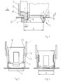
- Each drawing is an orthogonal elevation.
- the engagement composed of a sensor of door openness of household appliances (junction member) and a front wall of a washing machine (sheet-type carrier support) is a detachable connection of an inserting projection 1 of said sensor (a material part) and an opening 2 of a front wall of a washing machine (intangibility) with said inserting projection providing an orifice for entering a latch (not shown) arranged on a wing of a door of said washing machine, said sensor being fastened on the inner side of said front wall of said washing machine, and said inserting projection 1, when assembled, residing on the outer side of said front wall of said washing machine, thus visible from the outside.
- the opening 2 is rectangular having a long side a and a short side b with said long side constituting vertical limitations of said opening and said short side constituting horizontal limitations of said opening.
- the extent a of the inserting projection 1 corresponds to the extent a of the opening 2.
- the inserting projection 1 has a surplus of said extent (FIG. 1). With a first end, it has a front bar-shaped or substantially bar-like extension 3 parallel to the side a and extending beyond the side b, and with a second end, it has a rear bar-shaped or substantially bar-like extension 4 also parallel to the side a and extending beyond the side b.
- Each of them provides a support area 3', 4' oriented to the outer surface O of the front wall of the washing machine with the normal spacing from the supporting area L of the junction member being adapted to the thickness ⁇ of the material of the front wall of the washing machine.
- the support area 3' of the bar-like extension 3 constitutes a bearing surface to retain the side a of the opening 2 with the riser 5, then abutting the side a , being arranged normally to the support area 3' and projecting into the inside of the junction member.
- the bar-like extension 4 of the inserting projection 1 provides a trough-like recess 6 having a width b', whose distal edge is flush with the side a of the opening 2, while its proximal edge is flush with an outer surface F of a front wall of a housing of the junction member.
- the outer surface F of the front wall of the housing of the junction member is limited by two L-sections 7 positioned normally to the front wall of the washing machine.
- the front wall of the housing of the junction member and the L-sections 7 constitute a C-section arranged normally to the recess 6.
- a slide plate 8 is adapted to and inserted into said C-section that in this case acts as a guidance.
- a front end of the slide plate 8 is shaped to form a bar-like feather 9 having a length a , a thickness b' and a height equal to the sum of the depression of the recess 6 and the thickness ⁇ of the material of the front wall of the washing machine.
- the two notches 12 slide over the two counter notches 13 and engage them in the position of accommodating the bar-like feather 9 in the trough-like recess 6.
- the disassembling of the slide plate 8 precedes in the reverse way.
- junction member a sensor of door openness of household appliances
- sheet-type carrier support a front wall of a drum-type household machine
Landscapes
- Engineering & Computer Science (AREA)
- Textile Engineering (AREA)
- Main Body Construction Of Washing Machines And Laundry Dryers (AREA)
- Coupling Device And Connection With Printed Circuit (AREA)
- Buckles (AREA)
Abstract
Description
- The present invention relates to an engagement of a junction member and a sheet-type carrier support with said junction member being, e.g., a receptacle of a closure of a drum-type household machine, preferably a receptacle of a safety closure of said drum-type household machine, and said sheet-type carrier support being, e.g., a front wall of said drum-type household machine, with said engagement constituting a detachable connection of an inserting projection of said junction member (a material member) and an opening provided in said sheet-type carrier support (intangibility).
- An engagement of an inserting projection of a closure of a drum-type household machine and a front wall of said drum-type household machine, precisely a device for locking the closure door of a washing machine, is known from the patent specification No. EP1418266 (Rocchitelli). When incorporated, said device evidently resides in registry with a horizontal diameter of a door of said washing machine. In a front wall of the washing machine, three recesses arranged in a vertical line are foreseen to locate said device as to the position thereof, with the mutual spacing of their two outer recesses being large enough to establish sufficient anchoring rigidity, but too large to arrange said three recesses along a horizontal line if taking into account a given configuration of a washing machine. The usability of said known engagement is thus limited.
- Looking for an engagement of a junction member and a sheet-type carrier support being invariant to the orientation of said junction member with respect to said carrier support, more precisely looking for an engagement of a junction member and a sheet-type carrier support being substantially invariant to the configuration of a front wall of the machine, it is a goal of the present invention to provide an engagement based on a single recess.
- According to the present invention, said goal is obtained so that with a front bar-shaped extension said inserting projection of a junction member as set forth in the introductory part of this specification provides a substantially trough-shaped or a trough-like recess, whose distal edge is flush with a side of an opening provided in said sheet-type carrier support, while its proximal edge is flush with an outer surface of a front wall of a housing of said junction member. The words a trough-shaped or a trough-like recess indicate each and every intangibility serving as a receptacle to accommodate a material part adapted to it, and the terms distal/proximal refer to the position of a functional unit of said junction member relative to said front bar-shaped extension. The mounting of the inserting projection into the opening is evidently facilitated if said recess residing with said front bar-shaped extension of said junction member is a trough-shaped recess.
- Besides, with the side of said recess, said outer surface of the front wall of the housing of the junction member is limited, according to the present invention, by two L-sections with said front wall of the housing of said junction member and said L-sections constituting a C-section arranged normally to said recess. Said L-sections are advantageously used to increase the stability of the mounted junction member since they reside outside the area of the receiving opening.
- According to the invention, a slide plate is adapted to and inserted into said C-section, which in this case acts as a guidance. Actually, the substance of the present invention resides in said slide plate since no tool is required for its inserting and removal, respectively.
- A front end of said slide plate is shaped to form a bar-like or a substantially bar-like feather adapted to said recess with the term front determining the respective direction of inserting the slide plate. Obtaining a locking connection based on mating said recess and said bar-like feather is thus evident.
- In order to complete said locking connection it is important that, in the assembled state of the connection, the extension by height of said slide plate exceeds the upper edge of said L-sections. Namely, at the end of the slide plate residing opposite said bar-like feather there is, on each side thereof, actually at its upper side and flush with it, arranged, by means of a scarf hinge integral with it, a two-legged lever positioned in parallel with said L-section, with said scarf hinge acting preferably substantially as a spring and the end part of said L-section oriented to the front wall of the machine providing a notch preferably of the type of an indentation, while the other end of said two-legged lever serves as an unlocking key. According to the configuration of said levers as stated hereinbefore, on the edge of each L-section removed from the front wall of the machine there is provided, integral with it, a notch preferably of the type of a counter-indentation. Hence, said slide plate is secured against removal since indentations and counter-indentations mutually engage on the basis of yielding/returning capability of the indentations.
- Hereinafter, the present invention is disclosed in more detail on the basis of an embodiment of engagement of a junction member and a front wall of a washing machine, said embodiment being shown on two annexed sheets of drawings with said junction member comprising a sensor of door openness of household appliances (only shown by indication of an outline of its housing) of the Slovenian patent application P-200400269 (Lavrencic) filed on 28 September 2004.
- Each drawing is an orthogonal elevation.
- FIG. 1
- is a plan view of the longitudinal centric section of the captioned inventive engagement according to detail I in FIG. 8,
- FIG. 2
- is the captioned inventive engagement shown in direction of arrow II in FIG. 7 (prior-to-locking state),
- FIG. 3
- is the captioned inventive engagement shown in direction of arrow III in FIGS. 1 and 8 (locking state),
- FIGS. 4 to 7
- is an action illustration of embodying the captioned inventive engagement of a junction member and a sheet-type carrier support with said junction member being schematically shown,
- FIG. 8
- is substantially FIG. 1 with the junction member presented entirely, and
- FIG. 9
- is an opening in a front wall of a washing machine, to retain an inserting projection of a junction member.
- Actually, the engagement composed of a sensor of door openness of household appliances (junction member) and a front wall of a washing machine (sheet-type carrier support) is a detachable connection of an
inserting projection 1 of said sensor (a material part) and anopening 2 of a front wall of a washing machine (intangibility) with said inserting projection providing an orifice for entering a latch (not shown) arranged on a wing of a door of said washing machine, said sensor being fastened on the inner side of said front wall of said washing machine, and said insertingprojection 1, when assembled, residing on the outer side of said front wall of said washing machine, thus visible from the outside. - The
opening 2 is rectangular having a long side a and a short side b with said long side constituting vertical limitations of said opening and said short side constituting horizontal limitations of said opening. In this embodiment, the extent a of the inserting projection 1 (FIG. 3) corresponds to the extent a of theopening 2. - In comparison with the extent b of the
opening 2, theinserting projection 1 has a surplus of said extent (FIG. 1). With a first end, it has a front bar-shaped or substantially bar-like extension 3 parallel to the side a and extending beyond the side b, and with a second end, it has a rear bar-shaped or substantially bar-like extension 4 also parallel to the side a and extending beyond the side b. Each of them provides a support area 3', 4' oriented to the outer surface O of the front wall of the washing machine with the normal spacing from the supporting area L of the junction member being adapted to the thickness δ of the material of the front wall of the washing machine. In combination with ariser 5, the support area 3' of the bar-like extension 3 constitutes a bearing surface to retain the side a of theopening 2 with theriser 5, then abutting the side a, being arranged normally to the support area 3' and projecting into the inside of the junction member. By contrast with the bar-like extension 3, the bar-like extension 4 of theinserting projection 1 provides a trough-like recess 6 having a width b', whose distal edge is flush with the side a of theopening 2, while its proximal edge is flush with an outer surface F of a front wall of a housing of the junction member. - With the side of the
recess 6 outside the side a, with both lateral sides, the outer surface F of the front wall of the housing of the junction member is limited by two L-sections 7 positioned normally to the front wall of the washing machine. In said embodiment, the front wall of the housing of the junction member and the L-sections 7 constitute a C-section arranged normally to therecess 6. A slide plate 8 is adapted to and inserted into said C-section that in this case acts as a guidance. A front end of the slide plate 8 is shaped to form a bar-like feather 9 having a length a, a thickness b' and a height equal to the sum of the depression of therecess 6 and the thickness δ of the material of the front wall of the washing machine. - In the assembled state (FIG. 3), the extension by height of the slide plate 8 exceeds the upper edge of the L-
sections 7. With the end of the slide plate 8 residing opposite the bar-like feather 9 there is, on each side thereof, actually at its upper side and flush with it, arranged, by means of ashort scarf hinge 10 integral with it, a two-legged lever 11 positioned in parallel with the L-section 7, with thescarf hinge 10 acting as a spring and the end part of the L-section 7 oriented to the front wall of the washing machine providing anotch 12, while the other end of said two-legged lever serving as an unlocking key. With the edge of each L-section 7 removed from the front wall of the washing machine there is provided, integral with it, acounter notch 13. With inserting the slide plate 8 into the C-guidance, the twonotches 12 slide over the twocounter notches 13 and engage them in the position of accommodating the bar-like feather 9 in the trough-like recess 6. Of course, the disassembling of the slide plate 8 precedes in the reverse way. - In addition to the features disclosed hereinbefore, respective provisions are foreseen to obviate the looseness, if the captioned engagement is prepared for a thickness δ not known in advance or for loose tolerances, respectively, with said provisions being selected from the respective prior art.
- When realizing the captioned engagement of a junction member (a sensor of door openness of household appliances) and a sheet-type carrier support (a front wall of a drum-type household machine), said junction member is positioned to be inclined with respect to the
opening 2 and the front wall of the washing machine (FIG. 4) with the front bar-like extension 4 being pushed, in the direction V (FIG. 5), into theopening 2. As a result of the existence of therecess 6 then applied for entering the edge of theopening 2, the assembling is thus extremely simple. - Mutually, individual dimensions of the
inserting projection 1 are coordinated so as to make it possible the step of FIG. 5 to be followed by swinging said junction member in the direction of the arrow VI (FIG. 6), i.e., the rear bar-like extension 3, too, enters theopening 2. In the said state, the base area L of the junction member is supported by the inner surface of the front wall of the washing machine. - In a next step, while shifting in the direction of the arrow VII (FIG. 7), the
inserting projection 1, by its rear bar-like extension 3, abuts a first side a of theopening 2. In this position, the distal edge of therecess 6 is flush with a second side a of theopening 2 with therecess 6 of theinserting projection 1 being prepared to engage the bar-like feather 9 of the slide plate 8. - By the slide plate 8 shifted in the direction of the arrow VIII (FIG. 8), the bar-like feather 9 is accommodated in the
recess 6. Twonotches 12 engage twocounter notches 13 and, hence, the detachable connection of the junction member and the sheet-type carrier support is established. - Of course, the disengagement precedes in the reverse way.
- Due to the fact that with the captioned engagement a locking function (giving the word its strictest meaning) is constituted by two great sides of the
inserting projection 1 and theopening 2, there is obtained so called "narrow" guiding, and due to the fact that the captioned engagement is based on a single opening there are now possible all incorporating orientations of the junction member: a horizontal one that is considered most frequent, as well as a respective hinging or standing one.
Claims (7)
- Engagement of a junction member and a sheet-type carrier support with said junction member being, e.g., a receptacle of a closure of a drum-type household machine, preferably a receptacle of a safety closure of said drum-type household machine, and said sheet-type carrier support being, e.g., a front wall of said drum-type household machine, with said engagement constituting a detachable connection of an inserting projection (1) of said junction member, as a material member, and an opening (2) provided in said sheet-type carrier support, as intangibility, characterized in that, with a front bar-shaped extension (4), said inserting projection (1) provides a substantially trough-shaped or a trough-like recess (6), whose distal edge is flush with a side of the opening (2) provided in said sheet-type carrier support, while its proximal edge is flush with an outer surface (F) of a front wall of a housing of said junction member.
- Engagement of claim 1, characterized in that, with the side of said recess (6), said outer surface (F) of the front wall of the housing of the junction member is limited by two L-sections (7) with said front wall of the housing of said junction member and said L-sections constituting a C-section arranged normally to said recess (6).
- Engagement of claim 2, characterized in that a slide plate (8) is adapted to and inserted into said C-section.
- Engagement of claim 2 or 3, characterized in that a front end of said slide plate (8) is shaped to form a bar-like feather (9) adapted to said recess (6).
- Engagement of claim 3, characterized in that in the assembled state, the extension by height of said slide plate (8) exceeds the upper edge of said L-sections (7).
- Engagement of one of the preceding claims, characterized in that at the end of the slide plate (8) residing opposite said bar-like feather (9) there is, on each side thereof, actually at its upper side and flush with it, arranged, by means of a scarf hinge (10) integral with it, a two-legged lever (11) positioned in parallel with said L-section (7), with said scarf hinge (10) acting preferably substantially as a spring and the end part of said L-section (7) oriented to the front wall of the machine providing a notch (12) preferably of the type of an indentation, while the other end of said two-legged lever (11) serves as an unlocking key.
- Engagement of claim 6, characterized in that on the edge of each L-section (7) removed from the front wall of the machine there is provided, integral with it, a counter notch (13) preferably of the type of a counter indentation.
Priority Applications (3)
| Application Number | Priority Date | Filing Date | Title |
|---|---|---|---|
| EP05468003A EP1681386B1 (en) | 2005-01-14 | 2005-01-14 | Engagement of a junction member and a sheet-type carrier support |
| AT05468003T ATE419420T1 (en) | 2005-01-14 | 2005-01-14 | PLUG CONNECTION OF A CONNECTION COMPONENT AND A SHEET-TYPE SUPPORT |
| DE602005012047T DE602005012047D1 (en) | 2005-01-14 | 2005-01-14 | Plug connection of a connection component and a sheet-like carrier |
Applications Claiming Priority (1)
| Application Number | Priority Date | Filing Date | Title |
|---|---|---|---|
| EP05468003A EP1681386B1 (en) | 2005-01-14 | 2005-01-14 | Engagement of a junction member and a sheet-type carrier support |
Publications (2)
| Publication Number | Publication Date |
|---|---|
| EP1681386A1 true EP1681386A1 (en) | 2006-07-19 |
| EP1681386B1 EP1681386B1 (en) | 2008-12-31 |
Family
ID=34943354
Family Applications (1)
| Application Number | Title | Priority Date | Filing Date |
|---|---|---|---|
| EP05468003A Expired - Lifetime EP1681386B1 (en) | 2005-01-14 | 2005-01-14 | Engagement of a junction member and a sheet-type carrier support |
Country Status (3)
| Country | Link |
|---|---|
| EP (1) | EP1681386B1 (en) |
| AT (1) | ATE419420T1 (en) |
| DE (1) | DE602005012047D1 (en) |
Cited By (13)
| Publication number | Priority date | Publication date | Assignee | Title |
|---|---|---|---|---|
| ITTO20090098A1 (en) * | 2009-02-11 | 2010-08-12 | Bitron Spa | DOOR-LOCKING DEVICE, PARTICULARLY FOR APPLIANCES |
| ITTO20090099A1 (en) * | 2009-02-11 | 2010-08-12 | Bitron Spa | DOOR-LOCKING DEVICE, PARTICULARLY FOR APPLIANCES |
| WO2010101533A1 (en) * | 2009-03-06 | 2010-09-10 | Itw Metalflex, D.O.O. Tolmin | Junction component of screwless engagement |
| WO2012084483A1 (en) | 2010-12-24 | 2012-06-28 | Arcelik Anonim Sirketi | A washer/dryer comprising a lock |
| WO2014161784A1 (en) | 2013-04-05 | 2014-10-09 | Arcelik Anonim Sirketi | A washer/dryer comprising a lock |
| WO2019010020A1 (en) * | 2017-07-04 | 2019-01-10 | Illinois Tool Works Inc. | Door lock and electrical device |
| CN109209025A (en) * | 2017-07-04 | 2019-01-15 | 伊利诺斯工具制品有限公司 | Door lock and electrical equipment |
| WO2020112310A1 (en) | 2018-11-29 | 2020-06-04 | Illinois Tool Works Inc. | Door lock and electronic apparatus |
| US20210123181A1 (en) * | 2019-10-24 | 2021-04-29 | Emz-Hanauer Gmbh & Co. Kgaa | Door latch for a domestic electrical appliance and method for mounting such a door latch |
| CN112981867A (en) * | 2021-04-15 | 2021-06-18 | 温州天健电器有限公司 | Door lock without screw installation and washing machine with same |
| CN114059301A (en) * | 2020-08-07 | 2022-02-18 | 孔繁婷 | Electrical equipment and door lock thereof |
| EP4332294A1 (en) | 2022-09-05 | 2024-03-06 | Arçelik Anonim Sirketi | A laundry washer and/or dryer comprising a locking member |
| DE102024118985A1 (en) * | 2024-05-08 | 2025-11-13 | Emz-Hanauer Gmbh & Co. Kgaa | Door lock for a household appliance and method for mounting a door lock |
Citations (2)
| Publication number | Priority date | Publication date | Assignee | Title |
|---|---|---|---|---|
| US3455129A (en) * | 1967-07-10 | 1969-07-15 | Ilco Corp | Mortise lock construction |
| EP1418266A2 (en) * | 2002-11-08 | 2004-05-12 | Elettrotecnica Rold Srl | A device for locking the closure door of a washing machine |
-
2005
- 2005-01-14 AT AT05468003T patent/ATE419420T1/en not_active IP Right Cessation
- 2005-01-14 DE DE602005012047T patent/DE602005012047D1/en not_active Expired - Fee Related
- 2005-01-14 EP EP05468003A patent/EP1681386B1/en not_active Expired - Lifetime
Patent Citations (2)
| Publication number | Priority date | Publication date | Assignee | Title |
|---|---|---|---|---|
| US3455129A (en) * | 1967-07-10 | 1969-07-15 | Ilco Corp | Mortise lock construction |
| EP1418266A2 (en) * | 2002-11-08 | 2004-05-12 | Elettrotecnica Rold Srl | A device for locking the closure door of a washing machine |
Cited By (22)
| Publication number | Priority date | Publication date | Assignee | Title |
|---|---|---|---|---|
| ITTO20090099A1 (en) * | 2009-02-11 | 2010-08-12 | Bitron Spa | DOOR-LOCKING DEVICE, PARTICULARLY FOR APPLIANCES |
| WO2010092529A1 (en) * | 2009-02-11 | 2010-08-19 | Bitron S.P.A. | A door-locking device, particularly for a household appliance |
| WO2010092528A1 (en) * | 2009-02-11 | 2010-08-19 | Bitron S.P.A. | A door-locking device particularly for a household appliance |
| ITTO20090098A1 (en) * | 2009-02-11 | 2010-08-12 | Bitron Spa | DOOR-LOCKING DEVICE, PARTICULARLY FOR APPLIANCES |
| WO2010101533A1 (en) * | 2009-03-06 | 2010-09-10 | Itw Metalflex, D.O.O. Tolmin | Junction component of screwless engagement |
| CN102341541A (en) * | 2009-03-06 | 2012-02-01 | Itw美达丰(托尔明)公司 | Junction component of screwless engagement |
| WO2012084483A1 (en) | 2010-12-24 | 2012-06-28 | Arcelik Anonim Sirketi | A washer/dryer comprising a lock |
| WO2014161784A1 (en) | 2013-04-05 | 2014-10-09 | Arcelik Anonim Sirketi | A washer/dryer comprising a lock |
| CN109209025B (en) * | 2017-07-04 | 2026-06-16 | 伊利诺斯工具制品有限公司 | Door locks and electrical equipment |
| WO2019010020A1 (en) * | 2017-07-04 | 2019-01-10 | Illinois Tool Works Inc. | Door lock and electrical device |
| CN109209025A (en) * | 2017-07-04 | 2019-01-15 | 伊利诺斯工具制品有限公司 | Door lock and electrical equipment |
| WO2020112310A1 (en) | 2018-11-29 | 2020-06-04 | Illinois Tool Works Inc. | Door lock and electronic apparatus |
| EP3886670A1 (en) * | 2018-11-29 | 2021-10-06 | Illinois Tool Works Inc. | Door lock and electronic apparatus |
| US20220010478A1 (en) * | 2018-11-29 | 2022-01-13 | lllinois Tool Works Inc. | Door Lock And Electronic Apparatus |
| JP2022510235A (en) * | 2018-11-29 | 2022-01-26 | イリノイ トゥール ワークス インコーポレイティド | Door locks and electronic devices |
| US12351972B2 (en) | 2018-11-29 | 2025-07-08 | Illinois Tool Works Inc. | Door lock and electronic apparatus |
| US12129591B2 (en) * | 2019-10-24 | 2024-10-29 | Emz-Hanauer Gmbh & Co. Kgaa | Door latch for a domestic electrical appliance and method for mounting such a door latch |
| US20210123181A1 (en) * | 2019-10-24 | 2021-04-29 | Emz-Hanauer Gmbh & Co. Kgaa | Door latch for a domestic electrical appliance and method for mounting such a door latch |
| CN114059301A (en) * | 2020-08-07 | 2022-02-18 | 孔繁婷 | Electrical equipment and door lock thereof |
| CN112981867A (en) * | 2021-04-15 | 2021-06-18 | 温州天健电器有限公司 | Door lock without screw installation and washing machine with same |
| EP4332294A1 (en) | 2022-09-05 | 2024-03-06 | Arçelik Anonim Sirketi | A laundry washer and/or dryer comprising a locking member |
| DE102024118985A1 (en) * | 2024-05-08 | 2025-11-13 | Emz-Hanauer Gmbh & Co. Kgaa | Door lock for a household appliance and method for mounting a door lock |
Also Published As
| Publication number | Publication date |
|---|---|
| DE602005012047D1 (en) | 2009-02-12 |
| ATE419420T1 (en) | 2009-01-15 |
| EP1681386B1 (en) | 2008-12-31 |
Similar Documents
| Publication | Publication Date | Title |
|---|---|---|
| EP1681386B1 (en) | Engagement of a junction member and a sheet-type carrier support | |
| US8083299B2 (en) | Housing for a front-loading laundry appliance | |
| CN103763986B (en) | Drawer | |
| JP4701233B2 (en) | Latch for mounting in thin wall openings | |
| RU2605178C2 (en) | Dispenser for sheet products | |
| KR930009872A (en) | Manual operation dispensing unit for dual dispensing cartridges for two parts | |
| CN104411903B (en) | Fixation of door locks without screws into home appliances | |
| US20200315304A1 (en) | Insert for a watch bracelet | |
| JP5946715B2 (en) | Busbar adapter with mounting rail for mounting the switching device | |
| CN113431431A (en) | Adapter for mounting a retaining element of a door or window handle | |
| US7798583B2 (en) | Detent pin bearing retainer lock for a drawer slide | |
| EP2020718A1 (en) | Holding device for coupling an electrical apparatus to an apparatus mounting rail | |
| JP2010518909A (en) | Fixing device in the furniture body | |
| KR20100102690A (en) | Shopping cart having sliding handle | |
| US11112166B2 (en) | Door rack having a bottom latched on a basic body, and domestic refrigeration appliance having a door rack | |
| WO2005013750A1 (en) | Buckle | |
| KR20100115282A (en) | Buckle of belt | |
| GB1589512A (en) | Drawers | |
| KR100608457B1 (en) | Private box | |
| CN116157041B (en) | Adapter unit for connecting a drawer bottom to a side frame of a drawer, side frame and drawer | |
| JP4338431B2 (en) | Game board mounting structure | |
| KR19990005063A (en) | Glove box locking device of vehicle | |
| JP6906849B2 (en) | Distribution board | |
| US20050225218A1 (en) | Appliance console bottom attachment | |
| JP3766333B2 (en) | Cylinder lock mounting structure in cabinets, etc. |
Legal Events
| Date | Code | Title | Description |
|---|---|---|---|
| PUAI | Public reference made under article 153(3) epc to a published international application that has entered the european phase |
Free format text: ORIGINAL CODE: 0009012 |
|
| AK | Designated contracting states |
Kind code of ref document: A1 Designated state(s): AT BE BG CH CY CZ DE DK EE ES FI FR GB GR HU IE IS IT LI LT LU MC NL PL PT RO SE SI SK TR |
|
| AX | Request for extension of the european patent |
Extension state: AL BA HR LV MK YU |
|
| 17P | Request for examination filed |
Effective date: 20061116 |
|
| AKX | Designation fees paid |
Designated state(s): AT BE BG CH CY CZ DE DK EE ES FI FR GB GR HU IE IS IT LI LT LU MC NL PL PT RO SE SI SK TR |
|
| 17Q | First examination report despatched |
Effective date: 20070705 |
|
| GRAP | Despatch of communication of intention to grant a patent |
Free format text: ORIGINAL CODE: EPIDOSNIGR1 |
|
| GRAS | Grant fee paid |
Free format text: ORIGINAL CODE: EPIDOSNIGR3 |
|
| GRAA | (expected) grant |
Free format text: ORIGINAL CODE: 0009210 |
|
| AK | Designated contracting states |
Kind code of ref document: B1 Designated state(s): AT BE BG CH CY CZ DE DK EE ES FI FR GB GR HU IE IS IT LI LT LU MC NL PL PT RO SE SI SK TR |
|
| REG | Reference to a national code |
Ref country code: CH Ref legal event code: EP Ref country code: GB Ref legal event code: FG4D |
|
| REF | Corresponds to: |
Ref document number: 602005012047 Country of ref document: DE Date of ref document: 20090212 Kind code of ref document: P |
|
| REG | Reference to a national code |
Ref country code: IE Ref legal event code: FG4D |
|
| PG25 | Lapsed in a contracting state [announced via postgrant information from national office to epo] |
Ref country code: NL Free format text: LAPSE BECAUSE OF FAILURE TO SUBMIT A TRANSLATION OF THE DESCRIPTION OR TO PAY THE FEE WITHIN THE PRESCRIBED TIME-LIMIT Effective date: 20081231 Ref country code: PL Free format text: LAPSE BECAUSE OF FAILURE TO SUBMIT A TRANSLATION OF THE DESCRIPTION OR TO PAY THE FEE WITHIN THE PRESCRIBED TIME-LIMIT Effective date: 20081231 Ref country code: FI Free format text: LAPSE BECAUSE OF FAILURE TO SUBMIT A TRANSLATION OF THE DESCRIPTION OR TO PAY THE FEE WITHIN THE PRESCRIBED TIME-LIMIT Effective date: 20081231 Ref country code: SI Free format text: LAPSE BECAUSE OF FAILURE TO SUBMIT A TRANSLATION OF THE DESCRIPTION OR TO PAY THE FEE WITHIN THE PRESCRIBED TIME-LIMIT Effective date: 20081231 |
|
| NLV1 | Nl: lapsed or annulled due to failure to fulfill the requirements of art. 29p and 29m of the patents act | ||
| PG25 | Lapsed in a contracting state [announced via postgrant information from national office to epo] |
Ref country code: RO Free format text: LAPSE BECAUSE OF FAILURE TO SUBMIT A TRANSLATION OF THE DESCRIPTION OR TO PAY THE FEE WITHIN THE PRESCRIBED TIME-LIMIT Effective date: 20081231 Ref country code: LT Free format text: LAPSE BECAUSE OF FAILURE TO SUBMIT A TRANSLATION OF THE DESCRIPTION OR TO PAY THE FEE WITHIN THE PRESCRIBED TIME-LIMIT Effective date: 20081231 Ref country code: BE Free format text: LAPSE BECAUSE OF FAILURE TO SUBMIT A TRANSLATION OF THE DESCRIPTION OR TO PAY THE FEE WITHIN THE PRESCRIBED TIME-LIMIT Effective date: 20081231 Ref country code: EE Free format text: LAPSE BECAUSE OF FAILURE TO SUBMIT A TRANSLATION OF THE DESCRIPTION OR TO PAY THE FEE WITHIN THE PRESCRIBED TIME-LIMIT Effective date: 20081231 Ref country code: ES Free format text: LAPSE BECAUSE OF FAILURE TO SUBMIT A TRANSLATION OF THE DESCRIPTION OR TO PAY THE FEE WITHIN THE PRESCRIBED TIME-LIMIT Effective date: 20090411 |
|
| PG25 | Lapsed in a contracting state [announced via postgrant information from national office to epo] |
Ref country code: CZ Free format text: LAPSE BECAUSE OF FAILURE TO SUBMIT A TRANSLATION OF THE DESCRIPTION OR TO PAY THE FEE WITHIN THE PRESCRIBED TIME-LIMIT Effective date: 20081231 Ref country code: SE Free format text: LAPSE BECAUSE OF FAILURE TO SUBMIT A TRANSLATION OF THE DESCRIPTION OR TO PAY THE FEE WITHIN THE PRESCRIBED TIME-LIMIT Effective date: 20090331 Ref country code: MC Free format text: LAPSE BECAUSE OF NON-PAYMENT OF DUE FEES Effective date: 20090131 Ref country code: IS Free format text: LAPSE BECAUSE OF FAILURE TO SUBMIT A TRANSLATION OF THE DESCRIPTION OR TO PAY THE FEE WITHIN THE PRESCRIBED TIME-LIMIT Effective date: 20090430 Ref country code: PT Free format text: LAPSE BECAUSE OF FAILURE TO SUBMIT A TRANSLATION OF THE DESCRIPTION OR TO PAY THE FEE WITHIN THE PRESCRIBED TIME-LIMIT Effective date: 20090601 Ref country code: AT Free format text: LAPSE BECAUSE OF FAILURE TO SUBMIT A TRANSLATION OF THE DESCRIPTION OR TO PAY THE FEE WITHIN THE PRESCRIBED TIME-LIMIT Effective date: 20081231 |
|
| REG | Reference to a national code |
Ref country code: CH Ref legal event code: PL |
|
| PG25 | Lapsed in a contracting state [announced via postgrant information from national office to epo] |
Ref country code: SK Free format text: LAPSE BECAUSE OF FAILURE TO SUBMIT A TRANSLATION OF THE DESCRIPTION OR TO PAY THE FEE WITHIN THE PRESCRIBED TIME-LIMIT Effective date: 20081231 |
|
| REG | Reference to a national code |
Ref country code: IE Ref legal event code: MM4A |
|
| PG25 | Lapsed in a contracting state [announced via postgrant information from national office to epo] |
Ref country code: LI Free format text: LAPSE BECAUSE OF NON-PAYMENT OF DUE FEES Effective date: 20090131 Ref country code: CH Free format text: LAPSE BECAUSE OF NON-PAYMENT OF DUE FEES Effective date: 20090131 Ref country code: DE Free format text: LAPSE BECAUSE OF NON-PAYMENT OF DUE FEES Effective date: 20090801 Ref country code: DK Free format text: LAPSE BECAUSE OF FAILURE TO SUBMIT A TRANSLATION OF THE DESCRIPTION OR TO PAY THE FEE WITHIN THE PRESCRIBED TIME-LIMIT Effective date: 20081231 |
|
| PLBE | No opposition filed within time limit |
Free format text: ORIGINAL CODE: 0009261 |
|
| STAA | Information on the status of an ep patent application or granted ep patent |
Free format text: STATUS: NO OPPOSITION FILED WITHIN TIME LIMIT |
|
| REG | Reference to a national code |
Ref country code: FR Ref legal event code: ST Effective date: 20091030 |
|
| 26N | No opposition filed |
Effective date: 20091001 |
|
| PG25 | Lapsed in a contracting state [announced via postgrant information from national office to epo] |
Ref country code: IE Free format text: LAPSE BECAUSE OF NON-PAYMENT OF DUE FEES Effective date: 20090114 Ref country code: BG Free format text: LAPSE BECAUSE OF FAILURE TO SUBMIT A TRANSLATION OF THE DESCRIPTION OR TO PAY THE FEE WITHIN THE PRESCRIBED TIME-LIMIT Effective date: 20090331 |
|
| PG25 | Lapsed in a contracting state [announced via postgrant information from national office to epo] |
Ref country code: FR Free format text: LAPSE BECAUSE OF NON-PAYMENT OF DUE FEES Effective date: 20090302 |
|
| PG25 | Lapsed in a contracting state [announced via postgrant information from national office to epo] |
Ref country code: GR Free format text: LAPSE BECAUSE OF FAILURE TO SUBMIT A TRANSLATION OF THE DESCRIPTION OR TO PAY THE FEE WITHIN THE PRESCRIBED TIME-LIMIT Effective date: 20090401 |
|
| PG25 | Lapsed in a contracting state [announced via postgrant information from national office to epo] |
Ref country code: LU Free format text: LAPSE BECAUSE OF NON-PAYMENT OF DUE FEES Effective date: 20090114 |
|
| PG25 | Lapsed in a contracting state [announced via postgrant information from national office to epo] |
Ref country code: HU Free format text: LAPSE BECAUSE OF FAILURE TO SUBMIT A TRANSLATION OF THE DESCRIPTION OR TO PAY THE FEE WITHIN THE PRESCRIBED TIME-LIMIT Effective date: 20090701 |
|
| PG25 | Lapsed in a contracting state [announced via postgrant information from national office to epo] |
Ref country code: TR Free format text: LAPSE BECAUSE OF FAILURE TO SUBMIT A TRANSLATION OF THE DESCRIPTION OR TO PAY THE FEE WITHIN THE PRESCRIBED TIME-LIMIT Effective date: 20081231 |
|
| PG25 | Lapsed in a contracting state [announced via postgrant information from national office to epo] |
Ref country code: CY Free format text: LAPSE BECAUSE OF FAILURE TO SUBMIT A TRANSLATION OF THE DESCRIPTION OR TO PAY THE FEE WITHIN THE PRESCRIBED TIME-LIMIT Effective date: 20081231 |
|
| PGFP | Annual fee paid to national office [announced via postgrant information from national office to epo] |
Ref country code: IT Payment date: 20120123 Year of fee payment: 8 Ref country code: GB Payment date: 20120126 Year of fee payment: 8 |
|
| GBPC | Gb: european patent ceased through non-payment of renewal fee |
Effective date: 20130114 |
|
| PG25 | Lapsed in a contracting state [announced via postgrant information from national office to epo] |
Ref country code: GB Free format text: LAPSE BECAUSE OF NON-PAYMENT OF DUE FEES Effective date: 20130114 |
|
| PG25 | Lapsed in a contracting state [announced via postgrant information from national office to epo] |
Ref country code: IT Free format text: LAPSE BECAUSE OF NON-PAYMENT OF DUE FEES Effective date: 20130114 |