EP4332020A1 - A packed kit of flashing and/or covering members for a roof window and a method for packing a kit of flashing and/or covering members - Google Patents
A packed kit of flashing and/or covering members for a roof window and a method for packing a kit of flashing and/or covering members Download PDFInfo
- Publication number
- EP4332020A1 EP4332020A1 EP23192179.2A EP23192179A EP4332020A1 EP 4332020 A1 EP4332020 A1 EP 4332020A1 EP 23192179 A EP23192179 A EP 23192179A EP 4332020 A1 EP4332020 A1 EP 4332020A1
- Authority
- EP
- European Patent Office
- Prior art keywords
- flashing
- covering members
- covering
- kit
- members
- Prior art date
- Legal status (The legal status is an assumption and is not a legal conclusion. Google has not performed a legal analysis and makes no representation as to the accuracy of the status listed.)
- Pending
Links
Images




Classifications
-
- B—PERFORMING OPERATIONS; TRANSPORTING
- B65—CONVEYING; PACKING; STORING; HANDLING THIN OR FILAMENTARY MATERIAL
- B65D—CONTAINERS FOR STORAGE OR TRANSPORT OF ARTICLES OR MATERIALS, e.g. BAGS, BARRELS, BOTTLES, BOXES, CANS, CARTONS, CRATES, DRUMS, JARS, TANKS, HOPPERS, FORWARDING CONTAINERS; ACCESSORIES, CLOSURES, OR FITTINGS THEREFOR; PACKAGING ELEMENTS; PACKAGES
- B65D85/00—Containers, packaging elements or packages, specially adapted for particular articles or materials
- B65D85/62—Containers, packaging elements or packages, specially adapted for particular articles or materials for stacks of articles; for special arrangements of groups of articles
-
- E—FIXED CONSTRUCTIONS
- E04—BUILDING
- E04D—ROOF COVERINGS; SKY-LIGHTS; GUTTERS; ROOF-WORKING TOOLS
- E04D13/00—Special arrangements or devices in connection with roof coverings; Protection against birds; Roof drainage ; Sky-lights
- E04D13/14—Junctions of roof sheathings to chimneys or other parts extending above the roof
- E04D13/147—Junctions of roof sheathings to chimneys or other parts extending above the roof specially adapted for inclined roofs
- E04D13/1473—Junctions of roof sheathings to chimneys or other parts extending above the roof specially adapted for inclined roofs specially adapted to the cross-section of the parts extending above the roof
- E04D13/1475—Junctions of roof sheathings to chimneys or other parts extending above the roof specially adapted for inclined roofs specially adapted to the cross-section of the parts extending above the roof wherein the parts extending above the roof have a generally rectangular cross-section
-
- B—PERFORMING OPERATIONS; TRANSPORTING
- B65—CONVEYING; PACKING; STORING; HANDLING THIN OR FILAMENTARY MATERIAL
- B65D—CONTAINERS FOR STORAGE OR TRANSPORT OF ARTICLES OR MATERIALS, e.g. BAGS, BARRELS, BOTTLES, BOXES, CANS, CARTONS, CRATES, DRUMS, JARS, TANKS, HOPPERS, FORWARDING CONTAINERS; ACCESSORIES, CLOSURES, OR FITTINGS THEREFOR; PACKAGING ELEMENTS; PACKAGES
- B65D5/00—Rigid or semi-rigid containers of polygonal cross-section, e.g. boxes, cartons or trays, formed by folding or erecting one or more blanks made of paper
- B65D5/20—Rigid or semi-rigid containers of polygonal cross-section, e.g. boxes, cartons or trays, formed by folding or erecting one or more blanks made of paper by folding-up portions connected to a central panel from all sides to form a container body, e.g. of tray-like form
- B65D5/2052—Rigid or semi-rigid containers of polygonal cross-section, e.g. boxes, cartons or trays, formed by folding or erecting one or more blanks made of paper by folding-up portions connected to a central panel from all sides to form a container body, e.g. of tray-like form characterised by integral closure-flaps
- B65D5/2066—Cooperating flaps fixed together by separate mechanical elements, e.g. staples, clips, straps, labels, tape
-
- B—PERFORMING OPERATIONS; TRANSPORTING
- B65—CONVEYING; PACKING; STORING; HANDLING THIN OR FILAMENTARY MATERIAL
- B65D—CONTAINERS FOR STORAGE OR TRANSPORT OF ARTICLES OR MATERIALS, e.g. BAGS, BARRELS, BOTTLES, BOXES, CANS, CARTONS, CRATES, DRUMS, JARS, TANKS, HOPPERS, FORWARDING CONTAINERS; ACCESSORIES, CLOSURES, OR FITTINGS THEREFOR; PACKAGING ELEMENTS; PACKAGES
- B65D5/00—Rigid or semi-rigid containers of polygonal cross-section, e.g. boxes, cartons or trays, formed by folding or erecting one or more blanks made of paper
- B65D5/20—Rigid or semi-rigid containers of polygonal cross-section, e.g. boxes, cartons or trays, formed by folding or erecting one or more blanks made of paper by folding-up portions connected to a central panel from all sides to form a container body, e.g. of tray-like form
- B65D5/2052—Rigid or semi-rigid containers of polygonal cross-section, e.g. boxes, cartons or trays, formed by folding or erecting one or more blanks made of paper by folding-up portions connected to a central panel from all sides to form a container body, e.g. of tray-like form characterised by integral closure-flaps
- B65D5/2076—Cooperating flaps glued together
-
- B—PERFORMING OPERATIONS; TRANSPORTING
- B65—CONVEYING; PACKING; STORING; HANDLING THIN OR FILAMENTARY MATERIAL
- B65D—CONTAINERS FOR STORAGE OR TRANSPORT OF ARTICLES OR MATERIALS, e.g. BAGS, BARRELS, BOTTLES, BOXES, CANS, CARTONS, CRATES, DRUMS, JARS, TANKS, HOPPERS, FORWARDING CONTAINERS; ACCESSORIES, CLOSURES, OR FITTINGS THEREFOR; PACKAGING ELEMENTS; PACKAGES
- B65D5/00—Rigid or semi-rigid containers of polygonal cross-section, e.g. boxes, cartons or trays, formed by folding or erecting one or more blanks made of paper
- B65D5/42—Details of containers or of foldable or erectable container blanks
- B65D5/44—Integral, inserted or attached portions forming internal or external fittings
- B65D5/50—Internal supporting or protecting elements for contents
- B65D5/5028—Elements formed separately from the container body
- B65D5/5035—Paper elements
- B65D5/5069—Capping elements, i.e. elements which are located onto one or more ends of the contents, before the contents are inserted into the package
-
- B—PERFORMING OPERATIONS; TRANSPORTING
- B65—CONVEYING; PACKING; STORING; HANDLING THIN OR FILAMENTARY MATERIAL
- B65D—CONTAINERS FOR STORAGE OR TRANSPORT OF ARTICLES OR MATERIALS, e.g. BAGS, BARRELS, BOTTLES, BOXES, CANS, CARTONS, CRATES, DRUMS, JARS, TANKS, HOPPERS, FORWARDING CONTAINERS; ACCESSORIES, CLOSURES, OR FITTINGS THEREFOR; PACKAGING ELEMENTS; PACKAGES
- B65D81/00—Containers, packaging elements, or packages, for contents presenting particular transport or storage problems, or adapted to be used for non-packaging purposes after removal of contents
- B65D81/02—Containers, packaging elements, or packages, for contents presenting particular transport or storage problems, or adapted to be used for non-packaging purposes after removal of contents specially adapted to protect contents from mechanical damage
- B65D81/05—Containers, packaging elements, or packages, for contents presenting particular transport or storage problems, or adapted to be used for non-packaging purposes after removal of contents specially adapted to protect contents from mechanical damage maintaining contents at spaced relation from package walls, or from other contents
- B65D81/053—Corner, edge or end protectors
-
- E—FIXED CONSTRUCTIONS
- E06—DOORS, WINDOWS, SHUTTERS, OR ROLLER BLINDS IN GENERAL; LADDERS
- E06B—FIXED OR MOVABLE CLOSURES FOR OPENINGS IN BUILDINGS, VEHICLES, FENCES OR LIKE ENCLOSURES IN GENERAL, e.g. DOORS, WINDOWS, BLINDS, GATES
- E06B3/00—Window sashes, door leaves, or like elements for closing wall or like openings; Layout of fixed or moving closures, e.g. windows in wall or like openings; Features of rigidly-mounted outer frames relating to the mounting of wing frames
- E06B3/30—Coverings, e.g. protecting against weather, for decorative purposes
-
- E—FIXED CONSTRUCTIONS
- E04—BUILDING
- E04D—ROOF COVERINGS; SKY-LIGHTS; GUTTERS; ROOF-WORKING TOOLS
- E04D13/00—Special arrangements or devices in connection with roof coverings; Protection against birds; Roof drainage ; Sky-lights
- E04D13/03—Sky-lights; Domes; Ventilating sky-lights
- E04D13/0305—Supports or connecting means for sky-lights of flat or domed shape
- E04D13/031—Supports or connecting means for sky-lights of flat or domed shape characterised by a frame for connection to an inclined roof
Definitions
- the present invention relates to a packed kit of flashing and/or covering members for a roof window, said kit comprising at least two flashing and/or covering members made from sheet metal and arranged in a cardboard box, each of said flashing and/or covering members having free edges formed by an interruption of the sheet metal, and said at least two flashing and/or covering members being fixated in relation to each other by a packaging component wrapped at least partially around them.
- the invention further relates to a method for packing a kit of flashing and/or covering members.
- covering and flashing which cover the roof window and the joint, respectively.
- Flashing members are typically provided in a separate cardboard box, while at least some of the covering members are typically pre-attached to the roof window.
- smaller members are typically wrapped in plastic, thereby preventing them from scratching other components and being scratched themselves.
- this and further objects are achieved with a packed kit of flashing and/or covering members of the kind mentioned in the introduction, which is furthermore characterised in that the packaging component covers at least one free edge of each of said at least two flashing and/or covering member, and that the packaging component consists of one or more paper-based materials.
- the plastic previously used for wrapping the flashing and/or covering members has typically been made from polyethylene (PE) or polypropylene (PP). These materials are cheap, lightweight, and can be sufficiently soft to not course abrasive damage to flashing and/or covering members during handling and transportation in the packed state.
- PE polyethylene
- PP polypropylene
- the use of such polymers requires that the cardboard box and the packaging component will have to be separated in different fractions for recycling.
- the paper-based packaging component belongs to the same fraction as the cardboard box, which considerably increases the likelihood of the packaging materials actually being recycled instead of just being disposed of as combustible waste.
- packaging components made from a paper-based material may be biologically degradable.
- Lightweight packaging components such as plastic wrappings, are easily caught by wind when installing a roof window on a roof of building and may easily end up in nature or other places where they cannot be collected by the installer. While it is of course not the intention to leave packaging material behind, a biodegradable packaging component does little harm.
- the packed kit of flashing and/or covering members according to the invention may thus both reduce the amount of packaging material used, increase the likelihood of the packaging material being recycle, and reduce the risk of non- or slowly biodegradable material ending up in nature. All these factors contribute to a reduced climate footprint compared to prior art packed kit of flashing and/or covering members.
- the packaging component may include one or more items chosen from the group consisting of: paper bags, paper ribbons, cartons, and retainers made from folded cardboard.
- Paper ribbons are to be understood as including also paper straps, i.e. paper strips of a relatively small width, and tape, i.e. ribbons with an adhesive applied to one or both sides.
- the packaging component may form part of the cardboard box or be attached thereto, for example by means of adhesive or staples.
- the packaging component may be kept in place in relation to the flashing and/or covering members by being attached to flashing and/or covering members, for example by means of adhesive, and/or by being attached to itself, for example by means of adhesive, tape, staples, or other mechanical fasteners.
- paper and cardboard are usually made from wood-fibres, other plant fibres including fibres originating from straw, bamboo, bagasse, esparto, other grasses, hemp, flax, and cotton may also be used, including combinations of different types of fibres.
- alternative materials such as the glue or adhesive, is acceptable, but a maximum of 3% is recommended.
- weldable paper i.e. paper where a meltable polymer has been mixed into the paper material
- said polymer preferably being biodegradable
- the packaging component comprises a wrapper made from cardboard or paperboard and comprising at least one cover flap extending over and covering a free edge of each of said at least two flashing and/or covering members.
- the wrapper may be made from a single sheet of material or by two or more interconnected parts.
- the at least one cover flap may be attached to another section of the wrapper or to a flashing and/or covering member by an adhesive or tape, thereby keeping it in its intended position and helping to prevent that the wrapper comes off the flashing and/or covering members.
- the wrapper may be retained in a packed state by a ribbon or a string.
- the ribbon or string may also be in contact with the flashing and/or covering members and may help keeping the flashing and/or covering members in their intended mutual position, such as a stacked position.
- a ribbon or string may be attached to wrapper or be attached to itself, for example welding or a knot or by using a tape or a clamp.
- the wrapper may comprise one or more fixation flaps and one or more corresponding openings or indentations and may be retained in a packed state by each of the one or more fixation flaps being in engagement with one of the openings or indentations. In this way the wrapper may potentially be retained without the use of additional items, such as ribbons or string, and without the use of adhesive, welding, or the like.
- two separate packaging components are used, said separate packaging components being arranged at a distance from each other. This allows the packaging material to be applied only where needed and hence a minimal material consumption.
- Paper ribbon including paper tape, is presently considered well suited for use in this embodiment, but strips of corrugated cardboard or smaller wrappers may also be employed.
- each of the two separate packaging components may covers less than one fifth of the total length of the flashing and/or covering members in the packed state, preferably less than one tenth of the total length. This will not only keep the material consumption down but will also allow the flashing and/or covering members to be seen, thus potentially facilitating the work of the installer as it will be easy to identify the needed components during the installation process.
- flashing and/or covering members While reference is made only to flashing and/or covering members it is to be understood that other items, such as for example insulting members, may be arranged on or between the flashing and/or covering members and may thereby potentially retained by the packaging component(s). Particularly it is envisaged that smaller items, such as screws, can be accommodated in the cavities typically found in covering members and that two such covering members can be arranged with their concave sides facing each other, thereby forming a space between them suitable for accommodating such items.
- said at least two flashing and/or covering members comprise a plurality of side flashing members each having a first section configured for engagement with a roof structure and a second section configured for engagement with a frame of a roof window, said first and second sections extending from a bend on the sheet metal and substantially perpendicular to each other, each of said first and second sections having a longitudinal free edge extending substantially in parallel to the bend and two end free edges extending from the bend to the longitudinal free edge, where the side flashing members are stacked on top of each other so that their respective first and second sections extend adjacent to each other, and where the end free edges of at least one of the first and second section of each side flashing member are covered by the packaging component.
- the end free edges being covered by the packaging component entails that the side flashing members of the stack are prevented from sliding in relation to each other in the length direction defined by the longitudinal edges. In this way the side flashing members are kept in place by simple means while at the same time protecting the end free edges and reducing the risk of the installer cutting himself on the end free edges.
- said at least two flashing and/or covering members comprise a plurality of side flashing members each having a first section configured for engagement with a roof structure and a second section configured for engagement with a frame of a roof window, said first and second sections extending from a bend on the sheet metal substantially perpendicular to each other, each of said first and second section having a longitudinal free edge extending substantially in parallel to the bend and two end free edges extending from the bend to the longitudinal free edge, where the side flashing member are stacked on top of each other so that their respective first and second sections extend adjacent to each other, and where the longitudinal free edges of at least one of the first and second section of each side flashing member are covered by the packaging component.
- the longitudinal free edges being covered by the packaging component may also contribute to preventing the side flashing members from sliding in relation to each, only in a direction perpendicular to the length direction. Likewise, the longitudinal free edges are protected and the risk of the installer cutting himself reduced.
- a wrapper used on a stack of a plurality of side flashing members as described above may comprise a base section extending along at least one of the first section and the second section, a longitudinal cover flap extending over and covering the longitudinal free edges of the first or second sections, and two end cover flaps extending over and covering the end free edges of the first or second sections.
- the base section will protect the first and/or second section resting on it and may further serve to interconnect the longitudinal cover flap and the end cover flaps.
- the end cover flaps extend over and cover the end free edges of the first sections
- the longitudinal cover flap extends over and covers the longitudinal free edges of the second sections.
- the side flashing members are prevented from displacement along the length direction by the end cover flaps at the first sections and from displacement perpendicular to the length direction by the longitudinal cover flap at the second sections, thus providing a full fixation of the stack.
- a similar result may be achieved by providing the end cover flaps at the second sections and the longitudinal cover flap at the first sections, but it is presently preferred to protect the end free edges of the first sections since a tight overlap of the first sections is usually more important than a tight overlap at the second sections.
- the second sections may comprise attachment lobes, recesses etc. for mutual interconnection of the side flashing member and a longitudinal cover flap at the second sections may protect these.
- the longitudinal cover flap may extend past the bend so that end cover flaps provided at the other section of the side flashing member may be attached to the longitudinal cover flap, thereby fixating the stack.
- the base section and the longitudinal cover flap together cover both sides of both the first and second sections of the side flashing members. In this way the first and second sections will be well protected.
- end cover flaps by attachment to the longitudinal cover flap may be achieved by means of an adhesive, but if wanting to avoid the use of non-paper-based material, a ribbon or a string extending around the stack may be used for keeping the wrapper in place.
- said at least two flashing and/or covering members comprise two elongate covering members configured for extending along a sash member or a frame member of a roof window, each covering member having two opposite ends, where said elongate covering members are arranged side-by-side so that they form one elongate unit of substantially the same length as one covering member, and where the packaging component comprises a wrapper made from cardboard or paperboard, said wrapper extending substantially over the entire length of the elongate unit and covering at least one longitudinal free edge of each covering member.
- a wrapper extending substantially over the entire length of the elongate unit will usually protect not only the longitudinal edges but also at least a part of the surfaces of the covering members, which will be visible in the mounted state of the roof window. In this way the wrapping not only protects the longitudinal free edges, thus reducing the risk of deformation of the covering members and of the covering member damaging other items, but also reduces the risk of the covering members being scratched.
- the wrapper may be made for example from corrugated cardboard, which has shock absorbing properties, but is it also possible to use a single-layer paper or paperboard.
- the wrapper may be kept in place by the means of any of the methods mentioned above, including the use of paper ribbon, string, fixation flaps, adhesive and/or staples.
- a shock absorbing member such as an insulating member or a block of a paper-based honeycomb material may be arranged in a space between the covering members formed by the covering members being arranged with concave sides facing each other. Such a shock absorbing member will help prevent deformation by supporting the covering member from inside.
- said at least two flashing and/or covering members comprise two elongate covering members configured for extending along a sash member or a frame member of a roof window, each covering member having two opposite ends, where said elongate covering members are arranged side-by-side so that they form one elongate unit of substantially the same length as one covering member, and where the packaging component is wrapped around the elongate unit so that it covers free edges at both ends of the two covering members.
- the shape of the ends of covering members are typically of high importance to the watertightness of the roof window, as they may need to overlap with other covering members and/or be arranged at a particular distance from another part of a covering or flashing. Protecting the ends therefor considerably reduces the likelihood of the kit having to be discarded.
- the packaging component may extend from one end to the other, but to save material it is presently considered advantageous to use two separate packaging components which are arranged one at each end of the two covering members.
- One or more additional packaging components may be wrapped around the elongate unit at a distance from the ends of the two covering members, said additional packaging component(s) contributing to keeping the covering members together.
- Such additional packaging components may also be used in case the elongate unit comprises additional covering member(s) or other items for use in the installation of a roof window, which is/are substantially shorter than the two elongate covering members.
- the additional packaging component(s) may then be wrapped around the elongate unit at end(s) of the additional covering member or other items to protect end free edge(s) thereof or prevent it/them from damaging other things.
- a shock absorbing member may be arranged in a space between the two covering members as described above.
- the object is met by a method for packing a kit of flashing and/or covering members for a roof window, said kit comprising at least two flashing and/or covering members made from sheet metal, each of said at least two flashing and/or covering members having free edges formed by an interruption of the sheet metal, and said method comprising the steps of:
- the packaging component may also cover other free edges than those described.
- the packaging component may be used for protecting projecting parts, such as lobe, flaps or brackets, intended for use in connecting different components of a flashing and/or covering to each other or to a roof window.
- a packed kit 1 of flashing and/or covering members for a roof window is shown, said kit comprising a plurality of flashing and covering members 2 made from sheet metal and arranged in a cardboard box 3.
- a top flashing member 21 for use at the top of a frame of a roof window (not shown) and a bottom flashing member 22 for use at the bottom of a frame of a roof window are kept in place in the cardboard box by means of fixation blocks 4.
- the bottom flashing member 22 and a bag of screws 23 are attached to the bottom surface 31 of the cardboard box by strips 32 of an adhesive, here a holt-melt glue.
- Other smaller components such as a drainage gutter 24 may be loose or attached to other components, for example by mean of an adhesive.
- a set of side flashing members 25 wrapped in a packaging component in the form of a wrapper 51 has been attached to the bottom surface 31 of the cardboard box in a position which would otherwise have been occupied by a fixation block 4.
- a set of two elongate covering members 26 configured for extending along a sash member or a frame member of a roof window in a mounted state and arranged side-by-side so that they form one elongate unit of substantially the same length as one covering member, is kept together by two packaging components 52 being wrapped around the ends of the two covering members.
- the set of side flashing members 25 and the process of applying the wrapper 51 is shown in more detail in Figs 2-4 .
- the side flashing members 25 are made from sheet metal and each has a first section 251 configured for engagement with a roof structure and a second section 252 configured for engagement with a frame of a roof window. Said first and second sections extend from a bend 253 and are substantially perpendicular to each other, and each section has a longitudinal free edge 254, 255 extending substantially in parallel to the bend and two end free edges 256, 257 extending from the bend to the longitudinal free edge.
- a plurality of side flashing members is stacked on top of each other so that their respective first and second sections 251, 252 extend adjacent to each other, but only the one at the top of the stack is clearly visible in Fig. 2 .
- the side flashing members further have projecting flaps 258 configured for being bent over the longitudinal free edge 255 of the second section 252 of a neighbouring side flashing member during installation of a roof window.
- the wrapper 51 is made from corrugated cardboard and comprises a base section 511 on which the first section 251 of the lowermost side flashing member of the stack rests, a longitudinal cover flap 512, and two end cover flaps 513.
- the longitudinal cover flap 512 has been folded over the second section 252, whereby covering the longitudinal free edge 255 and the projecting flaps 258.
- the longitudinal cover flap is so long that it extends all the way down along the second sections, past the bend 253, and over the first sections 251, but this is not necessary in all embodiments. Extending over the first sections, however, has the advantage that when the two end cover flaps 513 have been bent over the end free edges 256 of the first sections 251, they can be attached to the longitudinal cover flap 512, here by means of an adhesive 514, resulting in the packed state shown in Fig. 4 .
- the side flashing members are fixated in relation to each other by the wrapper 51 in that the end cover flaps 513 prevent them from being displaced along the length direction L defined by the longitudinal edges and that the longitudinal cover flap 512 prevent them from being displaced perpendicular to the length direction.
- the longitudinal free edges 254 of the first sections 251 remain free in the packed state and the end free edges 257 of the second section 252 are only partially covered by the longitudinal cover flap 512 having a slightly larger length in the length direction L than the side flashing members. If even better protection is required, end cover flaps could also be provided at the second sections and the longitudinal cover flap 512 could be made even longer, allowing it to also be folded over the longitudinal free edges 254 of the first sections 251, or an additional longitudinal cover flap could be provided at the first sections 251. The possibility for the addition of further flaps for additional protection applies to all embodiments of the invention.
- the wrapper 51 is made from a single piece of cardboard, but it could also be made by interconnecting two or more parts.
- the base section 511 it may be desired for the base section 511 to be somewhat stiffer than the cover flaps to better support the stack of side flashing members during handling, and/or the longitudinal cover flap 512 might need to be stronger to protect the projecting flaps 258.
- one or more flaps may be attached to the base section and/or an additional piece of material may be applied on the section or flap needing reinforcement, for example by means of adhesive.
- FIG. 5-8 Other embodiments of the wrapper 51 and their uses are shown in Figs 5-8 , where the same reference numbers will be used as in Figs 2-4 for items have the same function even if they are not identical. Only the differences in relation to Figs 2-4 will be explained.
- Figs 5-8 the end cover flaps 513 are smaller than in Figs 1-4 and they are kept in place by a paper ribbon 515 extending all the way around the first sections 251 of the side flashing members. Compared to the embodiment in Figs 2-4 the amount of adhesive needed is reduced, but an additional packaging items in the form of the paper ribbon is introduced.
- the longitudinal cover flap 512 is larger than in Figs 2-5 so that the first section of the uppermost side flashing member of the stack is covered entirely. This may reduce the risk of the corners of the first section being damaged or damaging other items.
- the end free edges 257 of the second sections are visible in Fig. 6 .
- the side flashing members are of a different design without the projecting flaps 258 and the longitudinal cover flap 512 of the wrapper 51 is provided at the opposite side of the base section (not visible) so that it is folded over the longitudinal free edges (not visible) of the first sections 251 instead of over the longitudinal free edges 255 of the second sections 252.
- the first sections are protected even better, while the second sections, which are less sensitive due to the absence of projecting flaps, are left unprotected.
- the side flashing members will not be prevented from sliding in the width direction W1 of the first sections, so the stack will be fixated only in the length direction L and in the width direction W2 of the second sections. If the packed set is to be arranged in the cardboard box as shown in Fig. 1 , they will, however, be retained by the neighbouring flashing member.
- the flashing members are of the same design as in Fig. 7 , however the wrapper 51 in this embodiment does not include a longitudinal cover flap. Both longitudinal free edges 254, 255 thus remain free in the packed state.
- the first section 251 is in this embodiment only covered by the end cover flap 513 in the width direction of the first section W1 and kept in place by the paper ribbon 515.
- the side flashing members will not be prevented from sliding in the width direction W1 of the first sections, so the stack will be fixated only in the length direction L and in the width direction W2 of the second sections.
- Embodiments of the set of two elongate covering members 26 arranged side-by-side are shown in Figs 9-13 .
- paper ribbons 52 which constitute two separate packaging components, have been used at both ends and the two covering members 26.
- the two covering members both have an L-shaped cross-section when viewed along the length direction L, are arranged with their concave sides facing in the same direction so that no or only a small space is left between them.
- such covering members 26 typically have bents at their ends, so that the end free edge (not visible) is located on a section extending perpendicular or near perpendicular to the length direction L or even facing back towards the opposite end of the covering member. So even though the paper ribbons do not project over the end surface of the elongate unit formed by the two covering members 26, the end free edges may still be covered.
- the two covering members are instead arranged with their concave sides facing in opposite directions so that a space is left between them, and a shock absorbing member 53 in the form of a piece of paper-based honey-comb material is arranged in this space, supporting the covering members from inside.
- two additional packaging components 54 in the form of paper ribbons are wrapped around the elongate unit at a distance from the ends and at a distance from each other to keep the covering members together and keep the shock absorbing member 53 in place.
- each of the two separate packaging components at the ends covers one fourteenth of the total length of the covering members 26, and in the embodiment in Fig. 10 each of the two paper ribbons covers one ninth of the total length of the covering members.
- Figs 11-13 Details of the paper ribbons 52 used at the ends of the two covering members are shown in Figs 11-13 , where the covering members 26 are arranged in relation to each other as described with reference to Fig. 9 .
- the ribbon 52 is made from corrugated cardboard and is kept in place by a paper strap 521, which is attached to itself by a piece of paper tape 522.
- the end free edges (not visible) of the covering members 26 are found on sections extending back towards opposite ends of the covering member and it thus well protected, but the corrugated cardboard also provides protection for the folded ends 261 of the covering members in that it extends about 1 cm over the ends.
- the ribbon 52 is a paper taper which adheres to the covering members and to itself.
- the tape extends over the ends of the covering members and is closed onto itself, thereby enclosing the ends entirely. This provides a good protecting since the ribbon does not fall off unintentionally but may have the downside that it may be more difficult for the installer to remove the ribbon than with the embodiment in Fig. 11 .
- the tape does not have the same shock absorbing properties as corrugated cardboard.
- the ribbon 52 is made from paper, which is kept in place by being attached to itself by means of an adhesive.
- the location of the strip of adhesive is indicate by dotted lines 523 and it is to be understood that it is also possible to use other adhesive patterns or to weld the paper.
- One end 524 of the paper ribbon 52 is left unattached and may be used as a holding tab when removing the ribbon. By simply pulling on the unattached end 524 it will be possible to break either the adhesive or the paper, thereby releasing the covering members 26. This provides for a cheap and simply solution but provides limited protection of the end free edges.
- FIGs 14-17 further embodiments of sets of covering members 26 as those in Fig. 1 and Figs 9-13 are shown, but here with wrappers 55 extending substantially over the entire length of the elongate unit and covering longitudinal free edges of the covering members.
- the covering members are arranged in relation to each other as described with reference to Fig. 9
- the covering members are arranged in relation to each other as described with reference to Fig. 10 .
- the wrapper 55 extends all the way around the covering members with two sections 553, 554 overlapping each other and is attached to itself by two fixation flaps 551 in one 554 of the overlapping sections having been pushed into two corresponding openings (not visible) in the other 553 of the overlapping sections, leaving openings 552 where the flaps 551 used to be. This may be sufficient to keep the wrapper in place and keep the covering members together, but it is possible to supplement with for example one or more pieces of paper tape or a paper ribbon or a string.
- Fig. 15 resembles that in Fig. 14 except for the overlapping sections 553, 554 of the wrapper being present only at the ends of the elongate unit, the outer sections 554 being shorter than the inner sections 553. Furthermore, the two fixation flaps are formed by cuts into the edges of the outer sections 554, thus leaving indentations 555 when folded down rather than openings. The openings may also be replaced by indentations in an edge of the wrapper. This applies to the other embodiments as well.
- Fig. 16 also resembles that in Fig. 14 except for being provided with end cover flaps 556 and for the two fixation flaps being provided in these end cover flaps, leaving openings 552 when folded down. Furthermore, at longitudinal cover flap 557 is provided at a distance from both ends, helping to keep the wrapper closed at a position, where it would otherwise tend to open.
- Fig. 17 is fairly simple, consisting of a rectangular piece of cardboard being wrapped around the covering members and kept closed by means of a paper tape 558. It is to be understood that a similar piece of tape is used also at the opposite end of the elongate unit, and that one or more pieces of tape may also be used between the ends.
Landscapes
- Engineering & Computer Science (AREA)
- Mechanical Engineering (AREA)
- Civil Engineering (AREA)
- Structural Engineering (AREA)
- Architecture (AREA)
- Buffer Packaging (AREA)
Abstract
Description
- The present invention relates to a packed kit of flashing and/or covering members for a roof window, said kit comprising at least two flashing and/or covering members made from sheet metal and arranged in a cardboard box, each of said flashing and/or covering members having free edges formed by an interruption of the sheet metal, and said at least two flashing and/or covering members being fixated in relation to each other by a packaging component wrapped at least partially around them. The invention further relates to a method for packing a kit of flashing and/or covering members.
- When installing windows in a roof it is vital to ensure that both the roof window itself and the joint between the roof window and the roof structure is properly weather proofed. This is ensured by the use of covering and flashing, which cover the roof window and the joint, respectively. Making the covering members and flashing members from sheet metal combines the advantages of low weight and high weather resistances but makes them sensitive to damages caused by deformation and scratching. Flashing members are typically provided in a separate cardboard box, while at least some of the covering members are typically pre-attached to the roof window. To protect the flashing and/or covering members, which are not attached to the roof window, during handling and transportation, smaller members are typically wrapped in plastic, thereby preventing them from scratching other components and being scratched themselves. Larger members are typically protected from deformation by being attached to the cardboard box by means of an adhesive and/or by blocks of expanded polystyrene arranged inside the cardboard box and keeping the members in their intended positions. Such blocks may also prevent deformation of the cardboard box, thereby indirectly preventing that excessive loads affect the flashing and/or covering members. While these principles have worked very well, there is an ever-increasing demand for delivering products that are more environmentally friendly.
- With this background, it is an object of the invention to provide a packed kit of flashing and/or covering members, which has a smaller climate footprint, while maintaining a good protection of the flashing and/or covering members during transportation and handling.
- In a first aspect of the invention this and further objects are achieved with a packed kit of flashing and/or covering members of the kind mentioned in the introduction, which is furthermore characterised in that the packaging component covers at least one free edge of each of said at least two flashing and/or covering member, and that the packaging component consists of one or more paper-based materials.
- Experience has shown that the free edges of flashing and/or covering member are responsible for a very high percentage of the scratching damage caused to other component during handling and transportation, and that the free edges are particularly vulnerable to damage by deformation. Deformation of free edges may lead to a reduced water tightness of the installed roof window. By applying the packaging component such that it covers at least one free edge of each flashing and/or covering member it is thus not only possible to reduce the risk of the installed roof window not meeting aesthetic standards, but also to reduce the risk of insufficient water tightness.
- Less sensitive parts of the flashing and/or covering members may be left uncovered, thereby reducing the total amount of packaging material needed compared to when wrapping the flashing and/or covering members entirely.
- The plastic previously used for wrapping the flashing and/or covering members has typically been made from polyethylene (PE) or polypropylene (PP). These materials are cheap, lightweight, and can be sufficiently soft to not course abrasive damage to flashing and/or covering members during handling and transportation in the packed state. The use of such polymers, however, requires that the cardboard box and the packaging component will have to be separated in different fractions for recycling. The paper-based packaging component on the other hand belongs to the same fraction as the cardboard box, which considerably increases the likelihood of the packaging materials actually being recycled instead of just being disposed of as combustible waste.
- Another potential advantage of using packaging components made from a paper-based material is that they may be biologically degradable. Lightweight packaging components, such as plastic wrappings, are easily caught by wind when installing a roof window on a roof of building and may easily end up in nature or other places where they cannot be collected by the installer. While it is of course not the intention to leave packaging material behind, a biodegradable packaging component does little harm.
- The packed kit of flashing and/or covering members according to the invention may thus both reduce the amount of packaging material used, increase the likelihood of the packaging material being recycle, and reduce the risk of non- or slowly biodegradable material ending up in nature. All these factors contribute to a reduced climate footprint compared to prior art packed kit of flashing and/or covering members.
- The packaging component may include one or more items chosen from the group consisting of: paper bags, paper ribbons, cartons, and retainers made from folded cardboard. Paper ribbons are to be understood as including also paper straps, i.e. paper strips of a relatively small width, and tape, i.e. ribbons with an adhesive applied to one or both sides.
- The packaging component may form part of the cardboard box or be attached thereto, for example by means of adhesive or staples.
- The packaging component may be kept in place in relation to the flashing and/or covering members by being attached to flashing and/or covering members, for example by means of adhesive, and/or by being attached to itself, for example by means of adhesive, tape, staples, or other mechanical fasteners.
- It is to be understood that while paper and cardboard are usually made from wood-fibres, other plant fibres including fibres originating from straw, bamboo, bagasse, esparto, other grasses, hemp, flax, and cotton may also be used, including combinations of different types of fibres. In Europe, up to 5% of alternative materials, such as the glue or adhesive, is acceptable, but a maximum of 3% is recommended.
- The use of weldable paper, i.e. paper where a meltable polymer has been mixed into the paper material, is envisaged for at least some embodiments of the invention, said polymer preferably being biodegradable.
- In one embodiment the packaging component comprises a wrapper made from cardboard or paperboard and comprising at least one cover flap extending over and covering a free edge of each of said at least two flashing and/or covering members. The wrapper may be made from a single sheet of material or by two or more interconnected parts. By the cardboard or paperboard extending over the free edges, the edges are both protected and prevented from damaging other items. Particularly it may reduce the problem that metal edges made by cutting can be sharp and pose a danger to installers and other handling the flashing and/or covering members. Furthermore, the cardboard or paperboard extending over the free edges will help in keeping the flashing and/or covering members in there intended mutual position, such as a stacked position.
- The at least one cover flap may be attached to another section of the wrapper or to a flashing and/or covering member by an adhesive or tape, thereby keeping it in its intended position and helping to prevent that the wrapper comes off the flashing and/or covering members.
- In addition, or alternatively, the wrapper may be retained in a packed state by a ribbon or a string. The ribbon or string may also be in contact with the flashing and/or covering members and may help keeping the flashing and/or covering members in their intended mutual position, such as a stacked position. A ribbon or string may be attached to wrapper or be attached to itself, for example welding or a knot or by using a tape or a clamp.
- In addition, or alternatively, the wrapper may comprise one or more fixation flaps and one or more corresponding openings or indentations and may be retained in a packed state by each of the one or more fixation flaps being in engagement with one of the openings or indentations. In this way the wrapper may potentially be retained without the use of additional items, such as ribbons or string, and without the use of adhesive, welding, or the like.
- In one embodiment two separate packaging components are used, said separate packaging components being arranged at a distance from each other. This allows the packaging material to be applied only where needed and hence a minimal material consumption. Paper ribbon, including paper tape, is presently considered well suited for use in this embodiment, but strips of corrugated cardboard or smaller wrappers may also be employed.
- It is presently considered advantageous that each of the two separate packaging components may covers less than one fifth of the total length of the flashing and/or covering members in the packed state, preferably less than one tenth of the total length. This will not only keep the material consumption down but will also allow the flashing and/or covering members to be seen, thus potentially facilitating the work of the installer as it will be easy to identify the needed components during the installation process.
- While reference is made only to flashing and/or covering members it is to be understood that other items, such as for example insulting members, may be arranged on or between the flashing and/or covering members and may thereby potentially retained by the packaging component(s). Particularly it is envisaged that smaller items, such as screws, can be accommodated in the cavities typically found in covering members and that two such covering members can be arranged with their concave sides facing each other, thereby forming a space between them suitable for accommodating such items.
- In one embodiment said at least two flashing and/or covering members comprise a plurality of side flashing members each having a first section configured for engagement with a roof structure and a second section configured for engagement with a frame of a roof window, said first and second sections extending from a bend on the sheet metal and substantially perpendicular to each other, each of said first and second sections having a longitudinal free edge extending substantially in parallel to the bend and two end free edges extending from the bend to the longitudinal free edge, where the side flashing members are stacked on top of each other so that their respective first and second sections extend adjacent to each other, and where the end free edges of at least one of the first and second section of each side flashing member are covered by the packaging component.
- The end free edges being covered by the packaging component entails that the side flashing members of the stack are prevented from sliding in relation to each other in the length direction defined by the longitudinal edges. In this way the side flashing members are kept in place by simple means while at the same time protecting the end free edges and reducing the risk of the installer cutting himself on the end free edges.
- Side flashing members of this type are typically intended for being mounted so that they overlap in a cascading manner down along the sides of a roof window installed in an inclined roof structure. An unintended deformation of the end free edges may result in the side flashing members not being able to come into tight contact with each other at the overlaps, which may in turn result in the flashing not being watertight. Protecting the end free edges with a cover flap of a wrapper thus contributes to a reduced risk of the kit having to be discarded and thus reduces the overall climate footprint of the construction in which the kit is to be used.
- In one embodiment said at least two flashing and/or covering members comprise a plurality of side flashing members each having a first section configured for engagement with a roof structure and a second section configured for engagement with a frame of a roof window, said first and second sections extending from a bend on the sheet metal substantially perpendicular to each other, each of said first and second section having a longitudinal free edge extending substantially in parallel to the bend and two end free edges extending from the bend to the longitudinal free edge, where the side flashing member are stacked on top of each other so that their respective first and second sections extend adjacent to each other, and where the longitudinal free edges of at least one of the first and second section of each side flashing member are covered by the packaging component.
- As described above with reference to the end free edges, the longitudinal free edges being covered by the packaging component may also contribute to preventing the side flashing members from sliding in relation to each, only in a direction perpendicular to the length direction. Likewise, the longitudinal free edges are protected and the risk of the installer cutting himself reduced.
- An unintended deformation of the longitudinal edges may result in the side flashing members not being able to come into tight contact with each other at the overlaps or not being able to come into proper contact with either the roof structure or the frame of the roof window. Either of these may in turn result in the flashing not being watertight, and such a deformation may therefore result in that the kit has to be discarded as also described above.
- A wrapper used on a stack of a plurality of side flashing members as described above may comprise a base section extending along at least one of the first section and the second section, a longitudinal cover flap extending over and covering the longitudinal free edges of the first or second sections, and two end cover flaps extending over and covering the end free edges of the first or second sections. In this way the advantages of the two embodiments described above are combined, protecting both the longitudinal free edges and the end free edges. The base section will protect the first and/or second section resting on it and may further serve to interconnect the longitudinal cover flap and the end cover flaps.
- In one embodiment the end cover flaps extend over and cover the end free edges of the first sections, and the longitudinal cover flap extends over and covers the longitudinal free edges of the second sections. In this way the side flashing members are prevented from displacement along the length direction by the end cover flaps at the first sections and from displacement perpendicular to the length direction by the longitudinal cover flap at the second sections, thus providing a full fixation of the stack. A similar result may be achieved by providing the end cover flaps at the second sections and the longitudinal cover flap at the first sections, but it is presently preferred to protect the end free edges of the first sections since a tight overlap of the first sections is usually more important than a tight overlap at the second sections. Furthermore, the second sections may comprise attachment lobes, recesses etc. for mutual interconnection of the side flashing member and a longitudinal cover flap at the second sections may protect these.
- The longitudinal cover flap may extend past the bend so that end cover flaps provided at the other section of the side flashing member may be attached to the longitudinal cover flap, thereby fixating the stack. In one embodiment the base section and the longitudinal cover flap together cover both sides of both the first and second sections of the side flashing members. In this way the first and second sections will be well protected. By combining this embodiment with the full fixation provided by a longitudinal cover flap at one section and end cover flaps at the other section, the stack of side flashing members is fixated and well protected by simple means, thus both saving packaging material and reducing the risk of the kit having to be discarded.
- The fixation of end cover flaps by attachment to the longitudinal cover flap may be achieved by means of an adhesive, but if wanting to avoid the use of non-paper-based material, a ribbon or a string extending around the stack may be used for keeping the wrapper in place.
- In one embodiment, said at least two flashing and/or covering members comprise two elongate covering members configured for extending along a sash member or a frame member of a roof window, each covering member having two opposite ends, where said elongate covering members are arranged side-by-side so that they form one elongate unit of substantially the same length as one covering member, and where the packaging component comprises a wrapper made from cardboard or paperboard, said wrapper extending substantially over the entire length of the elongate unit and covering at least one longitudinal free edge of each covering member.
- Such covering members are of importance not only to the water tightness of the roof window but also to the visual appearance. A wrapper extending substantially over the entire length of the elongate unit will usually protect not only the longitudinal edges but also at least a part of the surfaces of the covering members, which will be visible in the mounted state of the roof window. In this way the wrapping not only protects the longitudinal free edges, thus reducing the risk of deformation of the covering members and of the covering member damaging other items, but also reduces the risk of the covering members being scratched.
- The wrapper may be made for example from corrugated cardboard, which has shock absorbing properties, but is it also possible to use a single-layer paper or paperboard.
- The wrapper may be kept in place by the means of any of the methods mentioned above, including the use of paper ribbon, string, fixation flaps, adhesive and/or staples.
- A shock absorbing member, such as an insulating member or a block of a paper-based honeycomb material may be arranged in a space between the covering members formed by the covering members being arranged with concave sides facing each other. Such a shock absorbing member will help prevent deformation by supporting the covering member from inside.
- In one embodiment, said at least two flashing and/or covering members comprise two elongate covering members configured for extending along a sash member or a frame member of a roof window, each covering member having two opposite ends, where said elongate covering members are arranged side-by-side so that they form one elongate unit of substantially the same length as one covering member, and where the packaging component is wrapped around the elongate unit so that it covers free edges at both ends of the two covering members. The shape of the ends of covering members are typically of high importance to the watertightness of the roof window, as they may need to overlap with other covering members and/or be arranged at a particular distance from another part of a covering or flashing. Protecting the ends therefor considerably reduces the likelihood of the kit having to be discarded.
- The packaging component may extend from one end to the other, but to save material it is presently considered advantageous to use two separate packaging components which are arranged one at each end of the two covering members. One or more additional packaging components may be wrapped around the elongate unit at a distance from the ends of the two covering members, said additional packaging component(s) contributing to keeping the covering members together.
- Such additional packaging components may also be used in case the elongate unit comprises additional covering member(s) or other items for use in the installation of a roof window, which is/are substantially shorter than the two elongate covering members. The additional packaging component(s) may then be wrapped around the elongate unit at end(s) of the additional covering member or other items to protect end free edge(s) thereof or prevent it/them from damaging other things.
- A shock absorbing member may be arranged in a space between the two covering members as described above.
- In a second aspect of the invention the object is met by a method for packing a kit of flashing and/or covering members for a roof window, said kit comprising at least two flashing and/or covering members made from sheet metal, each of said at least two flashing and/or covering members having free edges formed by an interruption of the sheet metal, and said method comprising the steps of:
- A) fixating said at least two flashing and/or covering members in relation to each other by wrapping a packaging component at least partially around them,
- B) arranging said at least two flashing and/or covering members in a cardboard box,
- a1) using a packaging component consisting of one or more paper-based materials, and
- a2) covering at least one free edge of each of said at least two flashing and/or covering member by the packaging component.
- The advantages described above of covering longitudinal free edges and/or end free edges and of using paper-based materials also applies to the second aspect, and it is to be understood that in both aspects the packaging component may also cover other free edges than those described. Particularly it is envisaged that the packaging component may be used for protecting projecting parts, such as lobe, flaps or brackets, intended for use in connecting different components of a flashing and/or covering to each other or to a roof window.
- In the following description embodiments of the invention will be described with reference to the schematic drawings, in which
-
Fig. 1 is a perspective view of a packed kit of flashing and/or covering members, -
Figs 2-3 show a set of side flashing members during application of a wrapper, -
Fig. 4 shows the set of side flashing members inFig. 2 and Fig. 3 in a packed state, -
Figs 5-8 show still further sets of side flashing members in a packed state, -
Figs 9-10 show sets of covering members in a packed state, -
Figs 11-13 show details of sets of covering members in a packed state, -
Figs 14-16 show sets of covering members in a packed state, and -
Fig. 17 show a detail of a set of covering members in a packed state. - Referring initially to
Fig. 1 , a packedkit 1 of flashing and/or covering members for a roof window is shown, said kit comprising a plurality of flashing and coveringmembers 2 made from sheet metal and arranged in acardboard box 3. - Some of the flashing and/or covering members, for example a
top flashing member 21 for use at the top of a frame of a roof window (not shown) and abottom flashing member 22 for use at the bottom of a frame of a roof window are kept in place in the cardboard box by means of fixation blocks 4. Thebottom flashing member 22 and a bag ofscrews 23 are attached to thebottom surface 31 of the cardboard box bystrips 32 of an adhesive, here a holt-melt glue. Other smaller components such as adrainage gutter 24 may be loose or attached to other components, for example by mean of an adhesive. - In the embodiment shown in
Fig. 1 a set ofside flashing members 25 wrapped in a packaging component in the form of awrapper 51 has been attached to thebottom surface 31 of the cardboard box in a position which would otherwise have been occupied by afixation block 4. Furthermore, a set of twoelongate covering members 26 configured for extending along a sash member or a frame member of a roof window in a mounted state and arranged side-by-side so that they form one elongate unit of substantially the same length as one covering member, is kept together by twopackaging components 52 being wrapped around the ends of the two covering members. - The set of
side flashing members 25 and the process of applying thewrapper 51 is shown in more detail inFigs 2-4 . - As may be seen in
Fig. 2 theside flashing members 25 are made from sheet metal and each has afirst section 251 configured for engagement with a roof structure and asecond section 252 configured for engagement with a frame of a roof window. Said first and second sections extend from abend 253 and are substantially perpendicular to each other, and each section has a longitudinalfree edge free edges second sections Fig. 2 . The side flashing members further have projectingflaps 258 configured for being bent over the longitudinalfree edge 255 of thesecond section 252 of a neighbouring side flashing member during installation of a roof window. - The
wrapper 51 is made from corrugated cardboard and comprises abase section 511 on which thefirst section 251 of the lowermost side flashing member of the stack rests, alongitudinal cover flap 512, and two end cover flaps 513. - Turning now also to
Fig. 3 , thelongitudinal cover flap 512 has been folded over thesecond section 252, whereby covering the longitudinalfree edge 255 and the projecting flaps 258. In this embodiment the longitudinal cover flap is so long that it extends all the way down along the second sections, past thebend 253, and over thefirst sections 251, but this is not necessary in all embodiments. Extending over the first sections, however, has the advantage that when the two end cover flaps 513 have been bent over the endfree edges 256 of thefirst sections 251, they can be attached to thelongitudinal cover flap 512, here by means of an adhesive 514, resulting in the packed state shown inFig. 4 . - In the packed state in
Fig. 4 , the side flashing members are fixated in relation to each other by thewrapper 51 in that the end cover flaps 513 prevent them from being displaced along the length direction L defined by the longitudinal edges and that thelongitudinal cover flap 512 prevent them from being displaced perpendicular to the length direction. - In the embodiment shown in
Fig. 2-4 the longitudinalfree edges 254 of thefirst sections 251 remain free in the packed state and the endfree edges 257 of thesecond section 252 are only partially covered by thelongitudinal cover flap 512 having a slightly larger length in the length direction L than the side flashing members. If even better protection is required, end cover flaps could also be provided at the second sections and thelongitudinal cover flap 512 could be made even longer, allowing it to also be folded over the longitudinalfree edges 254 of thefirst sections 251, or an additional longitudinal cover flap could be provided at the first sections 251.The possibility for the addition of further flaps for additional protection applies to all embodiments of the invention. - In the embodiment shown in
Fig. 2-4 thewrapper 51 is made from a single piece of cardboard, but it could also be made by interconnecting two or more parts. As an example, it may be desired for thebase section 511 to be somewhat stiffer than the cover flaps to better support the stack of side flashing members during handling, and/or thelongitudinal cover flap 512 might need to be stronger to protect the projecting flaps 258. In such cases one or more flaps may be attached to the base section and/or an additional piece of material may be applied on the section or flap needing reinforcement, for example by means of adhesive. - Other embodiments of the
wrapper 51 and their uses are shown inFigs 5-8 , where the same reference numbers will be used as inFigs 2-4 for items have the same function even if they are not identical. Only the differences in relation toFigs 2-4 will be explained. - In
Figs 5-8 the end cover flaps 513 are smaller than inFigs 1-4 and they are kept in place by apaper ribbon 515 extending all the way around thefirst sections 251 of the side flashing members. Compared to the embodiment inFigs 2-4 the amount of adhesive needed is reduced, but an additional packaging items in the form of the paper ribbon is introduced. - In
Fig. 6 thelongitudinal cover flap 512 is larger than inFigs 2-5 so that the first section of the uppermost side flashing member of the stack is covered entirely. This may reduce the risk of the corners of the first section being damaged or damaging other items. The endfree edges 257 of the second sections are visible inFig. 6 . - In
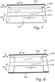
Fig. 7 the side flashing members are of a different design without the projectingflaps 258 and thelongitudinal cover flap 512 of thewrapper 51 is provided at the opposite side of the base section (not visible) so that it is folded over the longitudinal free edges (not visible) of thefirst sections 251 instead of over the longitudinalfree edges 255 of thesecond sections 252. In this way the first sections are protected even better, while the second sections, which are less sensitive due to the absence of projecting flaps, are left unprotected. Furthermore, in this embodiment the side flashing members will not be prevented from sliding in the width direction W1 of the first sections, so the stack will be fixated only in the length direction L and in the width direction W2 of the second sections. If the packed set is to be arranged in the cardboard box as shown inFig. 1 , they will, however, be retained by the neighbouring flashing member. - In
Fig. 8 the flashing members are of the same design as inFig. 7 , however thewrapper 51 in this embodiment does not include a longitudinal cover flap. Both longitudinalfree edges first section 251 is in this embodiment only covered by theend cover flap 513 in the width direction of the first section W1 and kept in place by thepaper ribbon 515. In this embodiment too, the side flashing members will not be prevented from sliding in the width direction W1 of the first sections, so the stack will be fixated only in the length direction L and in the width direction W2 of the second sections. - Embodiments of the set of two
elongate covering members 26 arranged side-by-side are shown inFigs 9-13 . - In
Fig. 9 paper ribbons 52, which constitute two separate packaging components, have been used at both ends and the two coveringmembers 26. The two covering members both have an L-shaped cross-section when viewed along the length direction L, are arranged with their concave sides facing in the same direction so that no or only a small space is left between them. - As is well known to the skilled person,
such covering members 26 typically have bents at their ends, so that the end free edge (not visible) is located on a section extending perpendicular or near perpendicular to the length direction L or even facing back towards the opposite end of the covering member. So even though the paper ribbons do not project over the end surface of the elongate unit formed by the two coveringmembers 26, the end free edges may still be covered. - In
Fig. 10 the two covering members are instead arranged with their concave sides facing in opposite directions so that a space is left between them, and ashock absorbing member 53 in the form of a piece of paper-based honey-comb material is arranged in this space, supporting the covering members from inside. Moreover, twoadditional packaging components 54 in the form of paper ribbons are wrapped around the elongate unit at a distance from the ends and at a distance from each other to keep the covering members together and keep theshock absorbing member 53 in place. - In the embodiment in
Fig. 9 each of the two separate packaging components at the ends covers one fourteenth of the total length of the coveringmembers 26, and in the embodiment inFig. 10 each of the two paper ribbons covers one ninth of the total length of the covering members. - Details of the
paper ribbons 52 used at the ends of the two covering members are shown inFigs 11-13 , where the coveringmembers 26 are arranged in relation to each other as described with reference toFig. 9 . - In
Fig. 11 theribbon 52 is made from corrugated cardboard and is kept in place by apaper strap 521, which is attached to itself by a piece ofpaper tape 522. The end free edges (not visible) of the coveringmembers 26 are found on sections extending back towards opposite ends of the covering member and it thus well protected, but the corrugated cardboard also provides protection for the folded ends 261 of the covering members in that it extends about 1 cm over the ends. - In
Fig. 12 , showing several sets of coveringmembers 26, theribbon 52 is a paper taper which adheres to the covering members and to itself. The tape extends over the ends of the covering members and is closed onto itself, thereby enclosing the ends entirely. This provides a good protecting since the ribbon does not fall off unintentionally but may have the downside that it may be more difficult for the installer to remove the ribbon than with the embodiment inFig. 11 . Moreover, the tape does not have the same shock absorbing properties as corrugated cardboard. - In
Fig. 13 theribbon 52 is made from paper, which is kept in place by being attached to itself by means of an adhesive. The location of the strip of adhesive is indicate bydotted lines 523 and it is to be understood that it is also possible to use other adhesive patterns or to weld the paper. - One
end 524 of thepaper ribbon 52 is left unattached and may be used as a holding tab when removing the ribbon. By simply pulling on theunattached end 524 it will be possible to break either the adhesive or the paper, thereby releasing the coveringmembers 26. This provides for a cheap and simply solution but provides limited protection of the end free edges. - Turning now to
Figs 14-17 further embodiments of sets of coveringmembers 26 as those inFig. 1 andFigs 9-13 are shown, but here withwrappers 55 extending substantially over the entire length of the elongate unit and covering longitudinal free edges of the covering members. InFigs 14-16 the covering members are arranged in relation to each other as described with reference toFig. 9 , and inFig. 17 the covering members are arranged in relation to each other as described with reference toFig. 10 . - In
Fig. 14 thewrapper 55 extends all the way around the covering members with twosections fixation flaps 551 in one 554 of the overlapping sections having been pushed into two corresponding openings (not visible) in the other 553 of the overlapping sections, leavingopenings 552 where theflaps 551 used to be. This may be sufficient to keep the wrapper in place and keep the covering members together, but it is possible to supplement with for example one or more pieces of paper tape or a paper ribbon or a string. - The embodiment in
Fig. 15 resembles that inFig. 14 except for the overlappingsections outer sections 554 being shorter than theinner sections 553. Furthermore, the two fixation flaps are formed by cuts into the edges of theouter sections 554, thus leavingindentations 555 when folded down rather than openings. The openings may also be replaced by indentations in an edge of the wrapper. This applies to the other embodiments as well. - The embodiment in
Fig. 16 also resembles that inFig. 14 except for being provided with end cover flaps 556 and for the two fixation flaps being provided in these end cover flaps, leavingopenings 552 when folded down. Furthermore, atlongitudinal cover flap 557 is provided at a distance from both ends, helping to keep the wrapper closed at a position, where it would otherwise tend to open. - The embodiment in
Fig. 17 is fairly simple, consisting of a rectangular piece of cardboard being wrapped around the covering members and kept closed by means of apaper tape 558. It is to be understood that a similar piece of tape is used also at the opposite end of the elongate unit, and that one or more pieces of tape may also be used between the ends. -
- 1
- packed kit of flashing and/or covering members
- 2
- flashing and/or covering members
- 21
- top flashing member
- 22
- bottom flashing member
- 23
- bag of screws
- 24
- drainage gutte
- 25
- side flashing member
- 251
- first section
- 252
- second section
- 253
- bend
- 254
- longitudinal free edge
- 255
- longitudinal free edge
- 256
- end free edge
- 257
- end free edge
- 258
- projecting flap
- 26
- elongate covering members
- 261
- folded end
- 3
- cardboard box
- 31
- bottom surface
- 32
- strips of adhesive
- 4
- fixation block
- 51
- wrapper
- 511
- base section
- 512
- longitudinal cover flap
- 513
- end cover flap
- 514
- adhesive
- 515
- paper ribbon
- 52
- packaging component
- 521
- paper strap
- 522
- paper tape
- 523
- location of the strip of adhesive
- 524
- unattached end
- 53
- shock absorbing member
- 54
- additional packaging component
- 55
- wrapper
- 551
- fixation flap
- 552
- opening
- 553
- overlapping section
- 554
- overlapping section
- 555
- indentation
- 556
- end cover flap
- 557
- longitudinal cover flap
- 558
- paper tape
- L
- length direction
- W1
- width direction of the first section
- W2
- width direction of the second section
Claims (17)
- A packed kit of flashing and/or covering members for a roof window, said kit comprising at least two flashing and/or covering members made from sheet metal and arranged in a cardboard box, each of said flashing and/or covering members having free edges formed by an interruption of the sheet metal, and said at least two flashing and/or covering members being fixated in relation to each other by a packaging component wrapped at least partially around them,
characterised in that the packaging component covers at least one free edge of each of said at least two flashing and/or covering members, and that the packaging component consists of one or more paper-based materials. - A packed kit of flashing and/or covering members according to claim 1, wherein the packaging component comprises a wrapper made from cardboard or paperboard and comprising at least one cover flap extending over and covering a free edge of each of said at least two flashing and/or covering members.
- A packed kit of flashing and/or covering members according to claim 2, wherein the at least one cover flap is attached to another section of the wrapper or to a flashing and/or covering member by an adhesive.
- A packed kit of flashing and/or covering members according to claim 2 or 3, wherein the wrapper is retained in a packed state by a ribbon or a string.
- A packed kit of flashing and/or covering members according to one or more of claims 2-4, wherein the wrapper comprises one or more fixation flaps and one or more corresponding openings or indentations, and wherein the wrapper is retained in a packed state by each of the one or more fixation flaps being in engagement with one of the openings or indentations.
- A packed kit of flashing and/or covering members according to one or more of claims 1-5, wherein two separate packaging components are use, said separate packaging components being arranged at a distance from each other.
- A packed kit of flashing and/or covering members according to claim 6, wherein each of the two separate packaging components covers less than one fifth of the total length of the flashing and/or covering members in the packed state, preferably less than one tenth of the total length.
- A packed kit of flashing and/or covering members according to one or more of the preceding claims, wherein said at least two flashing and/or covering members comprise a plurality of side flashing members each having a first section configured for engagement with a roof structure and a second section configured for engagement with a frame of a roof window, said first and second sections extending from a bend on the sheet metal and substantially perpendicular to each other, each of said first and second sections having a longitudinal free edge extending substantially in parallel to the bend and two end free edges extending from the bend to the longitudinal free edge, where the side flashing members are stacked on top of each other so that their respective first and second sections extend adjacent to each other, and where the end free edges of at least one of the first and second section of each side flashing member are covered by the packaging component.
- A packed kit of flashing and/or covering members according to one or more of the preceding claims, wherein said at least two flashing and/or covering members comprise a plurality of side flashing members each having a first section configured for engagement with a roof structure and a second section configured for engagement with a frame of a roof window, said first and second sections extending from a bend on the sheet metal and substantially perpendicular to each other, each of said first and second sections having a longitudinal free edge extending substantially in parallel to the bend and two end free edges extending from the bend to the longitudinal free edge, where the side flashing members are stacked on top of each other so that their respective first and second sections extend adjacent to each other, and where the longitudinal free edges of at least one of the first and second section of each side flashing member are covered by the packaging component.
- A packed kit of flashing and/or covering members according to one or more of claims 2-5 in combination with claim 8 or 9, wherein a base section of the wrapper extends along at least one of the first section and the second section, a longitudinal cover flap of the wrapper extends over and covering the longitudinal free edges of the first or second sections, and two end cover flaps of the wrapper extend over and covering the end free edges of the first or second sections.
- A packed kit of flashing and/or covering members according to claim 10, wherein the end cover flaps extend over and cover the end free edges of the first sections, and the longitudinal cover flap extending over and covering the longitudinal free edges of the second sections.
- A packed kit of flashing and/or covering members according to claim 10 or 11, wherein the base section and the longitudinal cover flap together cover both sides of both the first and second sections of the side flashing members.
- A packed kit of flashing and/or covering members according to one or more of claims 1-7, wherein said at least two flashing and/or covering members comprise two elongate covering members configured for extending along a sash member or a frame member of a roof window, each covering member having two opposite ends, where said elongate covering members are arranged side-by-side so that they form one elongate unit of substantially the same length as one covering member, and where the packaging component comprises a wrapper made from cardboard or paperboard, said wrapper extending substantially over the entire length of the elongate unit and covering at least one longitudinal free edge of each covering member.
- A packed kit of flashing and/or covering members according to one or more of claims 1-7 and 13, wherein said at least two flashing and/or covering members comprise two elongate covering members configured for extending along a sash member or a frame member of a roof window, each covering member having two opposite ends, where said elongate covering members are arranged side-by-side so that they form one elongate unit of substantially the same length as one covering member, and where the packaging component is wrapped around the elongate unit so that it covers free edges at both ends of the two covering members.
- A packed kit of flashing and/or covering members according to claims 6 and 14, wherein the two separate packaging components are arranged one at each end of the two covering members.
- A packed kit of flashing and/or covering members according to claim 15, wherein one or more additional packaging components is/are wrapped around the elongate unit at a distance from the ends of the two covering members, said additional packaging component(s) contributing to keeping the covering members together.
- A method for packing a kit of flashing and/or covering members for a roof window, said kit comprising at least two flashing and/or covering members made from sheet metal, each of said at least two flashing and/or covering members having free edges formed by an interruption of the sheet metal, and said method comprising the steps of:A) fixating said at least two flashing and/or covering members in relation to each other by wrapping a packaging component at least partially around them,B) arranging said at least two flashing and/or covering members in a cardboard box,characterised in that step A) further comprises:a1) using a packaging component consisting of one or more paper-based materials, anda2) covering at least one free edge of each of said at least two flashing and/or covering member by the packaging component.
Applications Claiming Priority (1)
| Application Number | Priority Date | Filing Date | Title |
|---|---|---|---|
| DKPA202270412A DK181780B1 (en) | 2022-08-19 | 2022-08-19 | A packed kit of flashing and/or covering members for a roof window and a method for packing a kit of flashing and/or covering members |
Publications (1)
| Publication Number | Publication Date |
|---|---|
| EP4332020A1 true EP4332020A1 (en) | 2024-03-06 |
Family
ID=87760684
Family Applications (1)
| Application Number | Title | Priority Date | Filing Date |
|---|---|---|---|
| EP23192179.2A Pending EP4332020A1 (en) | 2022-08-19 | 2023-08-18 | A packed kit of flashing and/or covering members for a roof window and a method for packing a kit of flashing and/or covering members |
Country Status (2)
| Country | Link |
|---|---|
| EP (1) | EP4332020A1 (en) |
| DK (1) | DK181780B1 (en) |
Cited By (1)
| Publication number | Priority date | Publication date | Assignee | Title |
|---|---|---|---|---|
| PL449486A1 (en) * | 2024-08-09 | 2026-02-16 | Fakro Pp Spółka Z Ograniczoną Odpowiedzialnością | Overlay for the sealing flange element and the method of packaging the sealing flange elements |
Citations (4)
| Publication number | Priority date | Publication date | Assignee | Title |
|---|---|---|---|---|
| JP2002173178A (en) * | 2000-12-01 | 2002-06-18 | Tostem Corp | Package for water-dripping member for skylight window |
| EP1710163A1 (en) * | 2005-04-08 | 2006-10-11 | VKR Holding A/S | Process, package and protecting elements for the packaging of a product having multiple components |
| US8459454B2 (en) * | 2009-07-22 | 2013-06-11 | Hunter Douglas Inc. | Packaging for window treatments |
| US10507949B1 (en) * | 2016-06-29 | 2019-12-17 | Amazon Technologies, Inc. | Convertible food containers |
Family Cites Families (2)
| Publication number | Priority date | Publication date | Assignee | Title |
|---|---|---|---|---|
| PL2748071T3 (en) * | 2011-10-04 | 2017-05-31 | Vkr Holding A/S | A packaging for a window and a method for packing |
| DK202070161A1 (en) * | 2020-03-10 | 2021-10-29 | Vkr Holding As | A packaging for installation elements for a roof window, a packed kit of installation elements, and method of providing a packaging for roof window installation elements |
-
2022
- 2022-08-19 DK DKPA202270412A patent/DK181780B1/en active IP Right Grant
-
2023
- 2023-08-18 EP EP23192179.2A patent/EP4332020A1/en active Pending
Patent Citations (4)
| Publication number | Priority date | Publication date | Assignee | Title |
|---|---|---|---|---|
| JP2002173178A (en) * | 2000-12-01 | 2002-06-18 | Tostem Corp | Package for water-dripping member for skylight window |
| EP1710163A1 (en) * | 2005-04-08 | 2006-10-11 | VKR Holding A/S | Process, package and protecting elements for the packaging of a product having multiple components |
| US8459454B2 (en) * | 2009-07-22 | 2013-06-11 | Hunter Douglas Inc. | Packaging for window treatments |
| US10507949B1 (en) * | 2016-06-29 | 2019-12-17 | Amazon Technologies, Inc. | Convertible food containers |
Cited By (1)
| Publication number | Priority date | Publication date | Assignee | Title |
|---|---|---|---|---|
| PL449486A1 (en) * | 2024-08-09 | 2026-02-16 | Fakro Pp Spółka Z Ograniczoną Odpowiedzialnością | Overlay for the sealing flange element and the method of packaging the sealing flange elements |
Also Published As
| Publication number | Publication date |
|---|---|
| DK202270412A1 (en) | 2024-02-21 |
| DK181780B1 (en) | 2024-12-13 |
Similar Documents
| Publication | Publication Date | Title |
|---|---|---|
| EP4089025A2 (en) | A packed roof window | |
| AU2012320962B2 (en) | A packaging for a window and a method for packing | |
| DK181780B1 (en) | A packed kit of flashing and/or covering members for a roof window and a method for packing a kit of flashing and/or covering members | |
| WO2023057030A1 (en) | Packed roof window products | |
| EP1405802A1 (en) | A package of wrapping material for roll shaped products | |
| US12515863B2 (en) | Packed roof window product, a method for packing a packed roof window product, and a method of unpacking a packed roof window product | |
| DK181669B1 (en) | Packed roof window products | |
| CZ37831U1 (en) | A set of cardboard box with a roof window deposited inside, where a retaining element of a ventilation damper is located and the use of the retaining element of the ventilation damper | |
| CZ37830U1 (en) | A carton assembly containing a carton containing a sunroof and packaging components to protect and hold the sunroof components | |
| EP4089022A2 (en) | Packed roof window product | |
| DK181313B1 (en) | Packed roof window products | |
| EP4324758A1 (en) | A packed roof window product and a method for packing a roof window product | |
| EP4089034B1 (en) | Packed installation kit comprising installation assemblies for a roof window system | |
| EP4412913B1 (en) | Packed roof window product | |
| EP4089031B1 (en) | Packed installation kit comprising an installation assembly with support beams as components | |
| KR20210046957A (en) | packing container made of card boards having honeycomb board core | |
| DK181617B1 (en) | A method for packaging a roof window and a packed roof window | |
| CN211618679U (en) | Carton capable of resisting extrusion of packing belt | |
| JPH0735165B2 (en) | Packaging box | |
| JPH08113263A (en) | Edge protection material for eaves grate packaging |
Legal Events
| Date | Code | Title | Description |
|---|---|---|---|
| PUAI | Public reference made under article 153(3) epc to a published international application that has entered the european phase |
Free format text: ORIGINAL CODE: 0009012 |
|
| STAA | Information on the status of an ep patent application or granted ep patent |
Free format text: STATUS: THE APPLICATION HAS BEEN PUBLISHED |
|
| AK | Designated contracting states |
Kind code of ref document: A1 Designated state(s): AL AT BE BG CH CY CZ DE DK EE ES FI FR GB GR HR HU IE IS IT LI LT LU LV MC ME MK MT NL NO PL PT RO RS SE SI SK SM TR |
|
| STAA | Information on the status of an ep patent application or granted ep patent |
Free format text: STATUS: REQUEST FOR EXAMINATION WAS MADE |
|
| 17P | Request for examination filed |
Effective date: 20240905 |
|
| RBV | Designated contracting states (corrected) |
Designated state(s): AL AT BE BG CH CY CZ DE DK EE ES FI FR GB GR HR HU IE IS IT LI LT LU LV MC ME MK MT NL NO PL PT RO RS SE SI SK SM TR |