EP4332003A1 - Verfahren und vorrichtung zur bodenzielpräzisionsausrichtung zur erfassung von satellitenbildern - Google Patents
Verfahren und vorrichtung zur bodenzielpräzisionsausrichtung zur erfassung von satellitenbildern Download PDFInfo
- Publication number
- EP4332003A1 EP4332003A1 EP23192792.2A EP23192792A EP4332003A1 EP 4332003 A1 EP4332003 A1 EP 4332003A1 EP 23192792 A EP23192792 A EP 23192792A EP 4332003 A1 EP4332003 A1 EP 4332003A1
- Authority
- EP
- European Patent Office
- Prior art keywords
- satellite
- time
- closest
- imaging
- ground
- Prior art date
- Legal status (The legal status is an assumption and is not a legal conclusion. Google has not performed a legal analysis and makes no representation as to the accuracy of the status listed.)
- Granted
Links
Images


Classifications
-
- B—PERFORMING OPERATIONS; TRANSPORTING
- B64—AIRCRAFT; AVIATION; COSMONAUTICS
- B64G—COSMONAUTICS; VEHICLES OR EQUIPMENT THEREFOR
- B64G1/00—Cosmonautic vehicles
- B64G1/10—Artificial satellites; Systems of such satellites; Interplanetary vehicles
- B64G1/1021—Earth observation satellites
-
- B—PERFORMING OPERATIONS; TRANSPORTING
- B64—AIRCRAFT; AVIATION; COSMONAUTICS
- B64G—COSMONAUTICS; VEHICLES OR EQUIPMENT THEREFOR
- B64G1/00—Cosmonautic vehicles
- B64G1/10—Artificial satellites; Systems of such satellites; Interplanetary vehicles
- B64G1/1021—Earth observation satellites
- B64G1/1028—Earth observation satellites using optical means for mapping, surveying or detection, e.g. of intelligence
-
- B—PERFORMING OPERATIONS; TRANSPORTING
- B64—AIRCRAFT; AVIATION; COSMONAUTICS
- B64G—COSMONAUTICS; VEHICLES OR EQUIPMENT THEREFOR
- B64G1/00—Cosmonautic vehicles
- B64G1/10—Artificial satellites; Systems of such satellites; Interplanetary vehicles
- B64G1/1021—Earth observation satellites
- B64G1/1035—Earth observation satellites using radar for mapping, surveying or detection, e.g. of intelligence
-
- B—PERFORMING OPERATIONS; TRANSPORTING
- B64—AIRCRAFT; AVIATION; COSMONAUTICS
- B64G—COSMONAUTICS; VEHICLES OR EQUIPMENT THEREFOR
- B64G1/00—Cosmonautic vehicles
- B64G1/22—Parts of, or equipment specially adapted for fitting in or to, cosmonautic vehicles
- B64G1/24—Guiding or controlling apparatus, e.g. for attitude control
- B64G1/242—Orbits and trajectories
-
- B—PERFORMING OPERATIONS; TRANSPORTING
- B64—AIRCRAFT; AVIATION; COSMONAUTICS
- B64G—COSMONAUTICS; VEHICLES OR EQUIPMENT THEREFOR
- B64G1/00—Cosmonautic vehicles
- B64G1/22—Parts of, or equipment specially adapted for fitting in or to, cosmonautic vehicles
- B64G1/24—Guiding or controlling apparatus, e.g. for attitude control
- B64G1/244—Spacecraft control systems
-
- G—PHYSICS
- G05—CONTROLLING; REGULATING
- G05D—SYSTEMS FOR CONTROLLING OR REGULATING NON-ELECTRIC VARIABLES
- G05D1/00—Control of position, course, altitude or attitude of land, water, air or space vehicles, e.g. using automatic pilots
- G05D1/0094—Control of position, course, altitude or attitude of land, water, air or space vehicles, e.g. using automatic pilots involving pointing a payload, e.g. camera, weapon, sensor, towards a fixed or moving target
-
- G—PHYSICS
- G05—CONTROLLING; REGULATING
- G05D—SYSTEMS FOR CONTROLLING OR REGULATING NON-ELECTRIC VARIABLES
- G05D1/00—Control of position, course, altitude or attitude of land, water, air or space vehicles, e.g. using automatic pilots
- G05D1/08—Control of attitude, i.e. control of roll, pitch, or yaw
-
- H—ELECTRICITY
- H04—ELECTRIC COMMUNICATION TECHNIQUE
- H04N—PICTORIAL COMMUNICATION, e.g. TELEVISION
- H04N23/00—Cameras or camera modules comprising electronic image sensors; Control thereof
- H04N23/60—Control of cameras or camera modules
- H04N23/64—Computer-aided capture of images, e.g. transfer from script file into camera, check of taken image quality, advice or proposal for image composition or decision on when to take image
-
- H—ELECTRICITY
- H04—ELECTRIC COMMUNICATION TECHNIQUE
- H04N—PICTORIAL COMMUNICATION, e.g. TELEVISION
- H04N23/00—Cameras or camera modules comprising electronic image sensors; Control thereof
- H04N23/60—Control of cameras or camera modules
- H04N23/695—Control of camera direction for changing a field of view, e.g. pan, tilt or based on tracking of objects
Definitions
- the disclosure relates to a method and apparatus for ground target precision orientation for satellite image acquisition.
- the ground station controlling the satellite predicts satellite orbit for a certain period of future time by using a ground-based orbit propagator so as to plan image acquisition mission.
- an orbit prediction error occurs in the along-track direction of the satellite track due to limited performance of the ground-based orbit propagator (e.g., 200 m of position error occurs after one day, and 1 km of position error occurs after 2 days, and this increases exponentially thereafter).
- the occurrence of orbit prediction error is higher than the low orbiting satellites due to increase in atmospheric drag. Further, the error occurs in the 3-axis direction rather than 1-axis direction, causing serious problems in the mission plan and operation.
- FIG. 1 is a diagram provided to explain a problem that occurs when a satellite images a ground target according to an imaging plan established by using a related ground-based orbit propagator.
- the ground station may receive a desired satellite position (P) for imaging, and calculate, by using a ground-based orbit propagator, a ground plan imaging time (T) corresponding to the desired satellite position (P) for imaging.
- the desired satellite position (P) for imaging is a determined position at which a desired area for imaging can be imaged in a ground-based predicted orbit.
- an image capturing payload mounted on the satellite starts capturing images of the ground target at the ground plan imaging time (T) and acquires the images.
- the ground-based predicted orbit includes orbit prediction errors, as illustrated in FIG. 1 , it is actually located at a position (P') at the ground plan imaging time (T). Therefore, discrepancy occurs between an area desired to be imaged and an area actually imaged.
- a technical problem to be solved by the disclosure is to provide a method and an apparatus for precision orientation toward a ground target when acquiring images through a satellite optical camera or an imaging radar payload.
- a method may include receiving a desired satellite position (P) for imaging from a ground station, and receiving a ground plan imaging time (T) or an algorithm execution time (T A ) from the ground station, in which the ground plan imaging time (T) may be calculated according to the desired satellite position (P) for imaging at a ground-based orbit propagator, and the algorithm execution time (T A ) is set to be earlier than the ground plan imaging time (T) by a predetermined amount of time, determining, based on a position error (E) calculated by using a difference between the desired satellite position (P) for imaging and the predicted satellite position (Q) output from the satellite-based orbit propagator, a closest satellite position (Q C ) and a closest satellite time (T C ) corresponding to when the satellite is closest to the desired satellite position (P) for imaging, and determining a corrected maneuvering attitude ( e , ⁇ ) for orienting a line-of-sight vector of an image capturing payload
- the satellite-based orbit propagator may receive position (P A ) and velocity (V A ) of the satellite at the algorithm execution time (T A ), and a waiting time (W) before imaging, and output the predicted satellite position (Q) as the position of the satellite at a time point when the waiting time (W) before imaging elapses from the algorithm execution time (T A ).
- the determining the closest satellite position (Q C ) and the closest satellite time (T C ) may include repeating calculating ⁇ T•i as an i-th waiting time (W(i)) before imaging, in which i is a natural number and ⁇ T is a predetermined increment of the waiting time before imaging, receiving the i-th waiting time (W(i)) before imaging and the position (P A ) and velocity (V A ) of the satellite at the algorithm execution time (T A ) from the satellite orbit propagator and calculating an i-th predicted satellite position (Q(i)), calculating an i-th position error (E(i)) corresponding to a difference between the i-th predicted satellite position (Q(i)) and the desired satellite position (P) for imaging, and comparing magnitudes of the i-th position error (E(i)) and the i-1-th position error (E(i-1)), while increasing i from '1' by '1' until the i-th position error (E(i)) is
- the determining the closest satellite position (Q C ) and the closest satellite time (T C ) may further include calculating the closest satellite position (Q C ) and the closest satellite time (T C ) by using the calculated waiting time (W(i)) before imaging and predicted satellite position (Q(i)).
- the closest satellite position (Q C ) and the closest satellite time (T C ) may be calculated by applying a nonlinear interpolation method or a precision filtering method to the calculated waiting time (W(i)) before imaging and predicted satellite position (Q(i)).
- the corrected maneuvering attitude ( e , ⁇ ) may include a maneuvering axis vector ( e ) and a maneuvering angle ( ⁇ ).
- h may be a distance from the position (P A ) of the satellite obtained at the algorithm execution time (T A ) to the ground surface.
- the corrected maneuvering attitude ( e , ⁇ ) may be obtained by reflecting an earth curvature and an orbit curvature of the satellite predicted by the satellite-based orbit propagator.
- an apparatus may include a communication part configured to receive a desired satellite position (P) for imaging from a ground station, and receive a ground plan imaging time (T) or an algorithm execution time (T A ) from the ground station, in which the ground plan imaging time (T) may be calculated according to the desired satellite position (P) for imaging at a ground-based orbit propagator, and the algorithm execution time (T A ) may be set to be earlier than the ground plan imaging time (T) by a predetermined amount of time, and a processor configured to determine, based on a position error (E) calculated by using a difference between the desired satellite position (P) for imaging and the predicted satellite position (Q) output from the satellite-based orbit propagator, a closest satellite position (Q C ) and a closest satellite time (T C ) corresponding to when the satellite is closest to the desired satellite position (P) for imaging, and determine a corrected maneuvering attitude ( e , ⁇ ) for orienting a line-of-
- E position error
- An orbit propagator is software (SW) that predicts position and velocity of a satellite in the near future of the orbit by fusing a satellite orbit model with observation data.
- a ground-based orbit propagator is satellite orbit prediction software implemented at the ground station.
- a ground-based predicted orbit is a satellite orbit for a certain future period of time predicted by the ground-based orbit propagator, and the normal prediction period is usually about 1 to 2 days.
- a satellite-based orbit propagator is satellite orbit prediction software mounted on the satellite.
- a satellite-based predicted orbit is a satellite orbit for a certain future period of time predicted by the satellite-based orbit propagator, and the normal prediction period is usually about 1 to 2 minutes, which is evaluated to be almost same as the actual orbit.
- GNSS global navigation satellite system
- HW hardware
- GNSS may include US global positioning system (GPS), Russian global navigation satellite system (GLONASS), European navigation system (GALILEO), and the like, but not limited thereto.
- a desired satellite position (P) for imaging may be planned at the ground station as a satellite position for imaging a ground target in the ground-based predicted orbit.
- a ground plan imaging time (T) may be planned by the ground station as the time of the desired satellite position (P) for imaging in the ground-based predicted orbit.
- An algorithm execution time (T A ) may be the time to execute an algorithm for determining the closest position and time and an algorithm for determining a corrected maneuvering attitude. Note that, in order to perform the algorithms before acquiring images from the satellite, the algorithm execution time (T A ) is set to a time earlier than the ground plan imaging time (T). That is, T A ⁇ T.
- the satellite position (P A ) and satellite velocity (V A ) at the time of executing the algorithm are the position and velocity of the satellite orbit obtained at the algorithm execution time (T A ) from the GNSS receiver mounted on the satellite.
- a waiting time (W) before imaging represents a waiting time from the algorithm execution time (T A ) as a reference time to any future imaging time in the satellite.
- a predicted satellite position (Q) represents the position of the satellite in the satellite-based predicted orbit at the time when the waiting time (W) before imaging elapses from the algorithm execution time (T A ) as a reference time.
- a closest satellite position (Q C ) represents the position of the satellite closest to the desired satellite position (P) for imaging in the satellite-based predicted orbit.
- a closest imaging time (T C ) represents the time of the satellite at the closest satellite position (Q C ) in the satellite-based predicted orbit.
- a closest waiting time (W C ) before closest imaging represents the waiting time from the algorithm execution time (T A ) as a reference time to the closest imaging time (Tc).
- a corrected maneuvering attitude ( e , ⁇ ) is a corrected maneuvering attitude for orienting a line-of-sight vector of the image capturing payload of the satellite to the ground target, and includes a maneuvering axis vector ( e ) and a maneuvering angle ( ⁇ ).
- a satellite altitude (h) is a distance from the earth's surface to the satellite, and can be calculated using the satellite position (P A ) at the time of executing the algorithm.
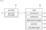
- FIG. 2 is a block diagram illustrating configuration of a satellite image acquisition system according to an embodiment.
- the ground station 100 may include a ground-based orbit propagator 110.
- the ground station 100 includes a communication device (not shown) that performs satellite communication with a satellite 200, and can exchange various information, commands, and data with the satellite 200.
- the ground-based orbit propagator 110 may be implemented in the ground station 100, and may be implemented as software (SW) that predicts position and velocity of the satellite in the near future in the orbit by fusing a satellite orbit model with observation data.
- SW software
- the satellite 200 may include a communication part 210, a computing device 220, a satellite-based orbit propagator 230, a GNSS receiver 240, and an image capturing payload 250.
- the communication part 210 allows the satellite 200 to exchange various types of information and data wirelessly with the ground station 100 through satellite communication.
- the computing device 220 may include one or more memories and one or more processors.
- the one or more memories may store one or more instructions. Further, the memory may store data used in the computing device 220 for various tasks related to the algorithm for determining the closest position and time and the algorithm for determining a corrected maneuvering attitude.
- the one or more processors may execute a process corresponding to the instruction stored in the memory.
- the satellite-based orbit propagator 230 may be implemented in the satellite 200, and may be implemented as software (SW) that predicts position and velocity of the satellite in the near future on the orbit by fusing the satellite orbit model with the observation data.
- SW software
- the GNSS receiver 240 may be implemented as a device that is mounted on the satellite 200 to measure the position and velocity of the satellite based on GNSS.
- the image capturing payload 250 may be implemented as a device such as an optical camera, an electro-optical camera, an infrared camera, an imaging radar, etc., which can capture images of the ground and acquire the images.
- FIG. 3 is a diagram illustrating a satellite image acquisition procedure according to an embodiment.
- the ground station 100 may receive the desired satellite position (P) for imaging from an external device or a ground station operator, at S300.
- the ground station 100 may use the ground-based orbit propagator 110 to calculate the ground plan imaging time (T) corresponding to the desired satellite position (P) for imaging in the ground-based predicted orbit, at S310. Further, the ground station 100 may set the algorithm execution time (T A ) that is earlier than the ground plan imaging time (T) by a predetermined amount of time, at S320.
- the predetermined amount of time may be set so that there is a sufficient time from the algorithm execution time (T A ) to complete calculating the closest satellite position (Q C ) of the satellite, the closest imaging time (T C ) and the corrected maneuvering attitude ( e , ⁇ ), and to complete maneuvering the satellite for orienting the line-of-sight vector of the image capturing payload 250 from the closest satellite position (Q C ) to the ground target. Then, the ground station 100 may transmit the desired satellite position (P) for imaging and the algorithm execution time (T A ) to the satellite, at 5330.
- the ground station 100 may skip the operation at 5320.
- the ground station 100 may transmit, to the satellite, the ground plan imaging time (T) instead of the algorithm execution time (T A ).
- the computing device 220 may set the algorithm execution time (T A ) that is earlier than the ground plan imaging time (T) by a predetermined amount of time.
- the computing device 220 executes the algorithm for determining the closest position and time so as to determine the closest satellite position (Q C ) and the closest satellite time (T C ) corresponding to when the satellite is closest to the desired satellite position (P) for imaging, based on a position error (E) calculated by using a difference between the desired satellite position (P) for imaging and the predicted satellite position (Q), at S350.
- the predicted satellite position (Q) is output from the satellite-based orbit propagator 230.
- the satellite-based orbit propagator 230 receives the position (P A ) and velocity (V A ) of the satellite at the algorithm execution time (T A ), and the waiting time (W) before imaging, and outputs the position of the satellite in the satellite-based predicted orbit as the predicted satellite position (Q) at a time point when the waiting time (W) before imaging elapses from the algorithm execution time (T A ).
- the position (P A ) and velocity (V A ) of the satellite are provided by the GNSS receiver 240.
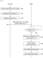
- FIG. 4 is a flowchart illustrating operation sequence of algorithm for determining the closest position and time according to an embodiment
- FIG. 5 is a diagram provided to explain concept of algorithm for determining the closest position and time according to an embodiment.
- the computing device 220 may calculate ⁇ T•i as the i-th waiting time (W(i)) before imaging, at S352.
- i is a natural number
- ⁇ T is a predetermined increment of the waiting time before imaging.
- the computing device 220 may input, to the satellite orbit propagator 230, the i-th waiting time (W(i)) before image, and the position (P A ) and velocity (V A ) of the satellite provided from the GNSS receiver 240 at the algorithm execution time (T A ) so as to calculate the i-th predicted satellite position (Q(i)), at S353.
- the computing device 220 may calculate an i-th position error E(i) corresponding to a difference between the i-th predicted satellite position Q(i) and the desired satellite position (P) for imaging, at S354.
- the computing device 220 may check whether the position error increases or not by comparing the i-th position error E(i) with the i-1-th position error E(i-1), at S355.
- a nonlinear interpolation method or a precision filtering method instead of a linear average value can be applied.
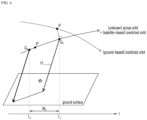
- FIG. 6 is a diagram schematically illustrating the closest satellite position and the closest imaging time calculated according to an embodiment.
- the satellite is located at the closest satellite position (Q C ) which is closest to the desired satellite position (P) for imaging in the satellite-based predicted orbit. Meanwhile, it can be seen that, when the line-of-sight vector of the image capturing payload 250 at the algorithm execution time (T A ) is maintained as it is, the line-of-sight vector 10 of the image capturing payload 250 at the closest satellite position (Q C ) cannot be oriented toward the ground target.
- the computing device 220 may determine a corrected maneuvering attitude ( e , ⁇ ) for orienting the line-of-sight vector of the image capturing payload 250 at the closest satellite position (Q C ) to the ground target, at S360.
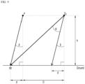
- FIG. 7 is a diagram conceptually illustrating the calculation of the corrected maneuvering attitude of the satellite according to an embodiment.
- the corrected maneuvering attitude ( e , ⁇ ) may include a maneuvering axis vector ( e ) and a maneuvering angle ( ⁇ ).
- the maneuvering angle ( ⁇ ) is an angle formed by a line-of-sight vector 10 and another line-of-sight vector 20.
- h may be calculated as a distance from the position (P A ) of the satellite obtained at the algorithm execution time (T A ) to the ground surface.
- FIG. 8 is a diagram provided to explain concept of acquiring a maneuvering angle when a ground target is located at a sub-satellite point of the satellite according to an embodiment.
- FIG. 9 is a diagram provided to explain concept of acquiring a maneuvering angle when a ground target is located at a distance away from a sub-satellite point of the satellite by an offset angle according to an embodiment.
- the orbit curvature, the curvature of the earth, or the like predicted from the satellite-based orbit propagator may be considered.
- the satellite 200 may perform satellite attitude maneuvering according to the corrected maneuvering attitude ( e , ⁇ ) corrected until the closest imaging time (T C ) so as to orient the line-of-sight vector of the image capturing payload 250 at the closest satellite position (Q C ) to the ground target, at S370.
- the satellite 200 may capture images of the ground target at the closest satellite position (Q C ) at the closest imaging time (T C ) so as to acquire the images, at S380.
- the embodiments described above may be implemented as a hardware component, a software component, and/or a combination of a hardware component and a software component.
- the devices, methods, and components described in the embodiments may be implemented by using one or more general computer or specific-purpose computer such as a processor, a controller, an arithmetic logic unit (ALU), a digital signal processor, a microcomputer, a field programmable gate array (FPGA), a programmable logic unit (PLU), a microprocessor, or any other device capable of executing instructions and responding thereto.
- the processing device may execute an operating system (OS) and one or more software applications executed on the operating system. Further, the processing device may access, store, operate, process, and generate data in response to the execution of software.
- OS operating system
- the processing device may access, store, operate, process, and generate data in response to the execution of software.
- the processing device may include a plurality of processing elements and/or a plurality of types of processing elements.
- the processing device may include a plurality of processors or one processor and one controller.
- other processing configurations such as a parallel processor are possible.
- the software may include a computer program, code, instructions, or a combination of one or more of the above, and may configure the processing device, or instruct the processing device independently or collectively to operate as desired.
- Software and/or data may be interpreted by the processing device or, in order to provide instructions or data to the processing device, may be embodied in any type of machine, component, physical device, virtual equipment, or computer storage medium or device, permanently or temporarily.
- the software may be distributed over networked computer systems and stored or executed in a distributed manner.
- the software and data may be stored on one or more computer-readable recording media.
- the method according to the embodiments may be implemented in the form of program instructions that can be executed through various computer means and recorded in a computer-readable medium.
- the computer readable medium may include program instructions, data files, data structures, and the like alone or in combination.
- the program instructions recorded on the medium may be those specially designed and configured for the purposes of the embodiments, or may be known and available to those skilled in computer software.
- Examples of computer readable recording medium include magnetic media such as hard disks, floppy disks, and magnetic tape, optical media such as CD-ROMs and DVDs, magneto-optical media such as floptical disks, and hardware devices specifically configured to store and execute program instructions such as ROM, RAM, flash memory, and the like.
- Examples of the program instructions include machine language codes such as those generated by a compiler, as well as high-level language codes that may be executed by a computer using an interpreter, and so on.
- the hardware device described above may be configured to operate as one or more software modules in order to perform the operations according to the embodiments, and vice versa.
Landscapes
- Engineering & Computer Science (AREA)
- Remote Sensing (AREA)
- Aviation & Aerospace Engineering (AREA)
- General Physics & Mathematics (AREA)
- Physics & Mathematics (AREA)
- Radar, Positioning & Navigation (AREA)
- Astronomy & Astrophysics (AREA)
- Chemical & Material Sciences (AREA)
- Combustion & Propulsion (AREA)
- Automation & Control Theory (AREA)
- Evolutionary Computation (AREA)
- Multimedia (AREA)
- Signal Processing (AREA)
- Control Of Position, Course, Altitude, Or Attitude Of Moving Bodies (AREA)
Applications Claiming Priority (1)
| Application Number | Priority Date | Filing Date | Title |
|---|---|---|---|
| KR1020220108627A KR102734082B1 (ko) | 2022-08-29 | 2022-08-29 | 인공위성 영상획득을 위한 지상표적 정밀 지향 방법 및 장치 |
Publications (2)
| Publication Number | Publication Date |
|---|---|
| EP4332003A1 true EP4332003A1 (de) | 2024-03-06 |
| EP4332003B1 EP4332003B1 (de) | 2025-10-08 |
Family
ID=87762847
Family Applications (1)
| Application Number | Title | Priority Date | Filing Date |
|---|---|---|---|
| EP23192792.2A Active EP4332003B1 (de) | 2022-08-29 | 2023-08-22 | Verfahren und vorrichtung zur bodenzielpräzisionsausrichtung zur erfassung von satellitenbildern |
Country Status (3)
| Country | Link |
|---|---|
| US (1) | US20240067364A1 (de) |
| EP (1) | EP4332003B1 (de) |
| KR (1) | KR102734082B1 (de) |
Families Citing this family (4)
| Publication number | Priority date | Publication date | Assignee | Title |
|---|---|---|---|---|
| US12392907B2 (en) * | 2022-05-18 | 2025-08-19 | Microsoft Technology Licensing, Llc | Satellite image management |
| CN119291797B (zh) * | 2024-10-15 | 2025-12-19 | 中国人民解放军国防科技大学 | 一种基于三颗同系列微光卫星组网获取重力波水平传播相速度的方法 |
| CN119903644B (zh) * | 2024-12-18 | 2025-11-14 | 武汉大学 | 一种立体测绘星上任务规划方法及系统 |
| CN119370346A (zh) * | 2024-12-26 | 2025-01-28 | 银河航天(北京)网络技术有限公司 | 姿态调整方法及装置 |
Citations (3)
| Publication number | Priority date | Publication date | Assignee | Title |
|---|---|---|---|---|
| KR20030046757A (ko) * | 2001-12-06 | 2003-06-18 | 한국전자통신연구원 | 위성의 궤도 예측에 의한 자동화된 영상촬영 계획 수립장치 및 그 방법 |
| US20180372882A1 (en) * | 2017-06-27 | 2018-12-27 | Korea Aerospace Research Institute | Method and apparatus for correcting satellite imaging time |
| EP3878758A1 (de) * | 2018-11-06 | 2021-09-15 | Korea Aerospace Research Institute | Verfahren und korrekturvorrichtung zur korrektur der position der aufnahme eines satellitenbildes |
Family Cites Families (2)
| Publication number | Priority date | Publication date | Assignee | Title |
|---|---|---|---|---|
| KR101227665B1 (ko) * | 2010-12-29 | 2013-01-30 | 세종대학교산학협력단 | 위성 데이터 스무딩을 이용한 정지궤도위성의 정밀 궤도 결정장치 및 결정 방법 |
| KR101949274B1 (ko) * | 2012-08-24 | 2019-02-19 | 한국전자통신연구원 | 정지 궤도 위성의 궤도 결정 장치 및 방법 |
-
2022
- 2022-08-29 KR KR1020220108627A patent/KR102734082B1/ko active Active
-
2023
- 2023-08-15 US US18/450,037 patent/US20240067364A1/en active Pending
- 2023-08-22 EP EP23192792.2A patent/EP4332003B1/de active Active
Patent Citations (3)
| Publication number | Priority date | Publication date | Assignee | Title |
|---|---|---|---|---|
| KR20030046757A (ko) * | 2001-12-06 | 2003-06-18 | 한국전자통신연구원 | 위성의 궤도 예측에 의한 자동화된 영상촬영 계획 수립장치 및 그 방법 |
| US20180372882A1 (en) * | 2017-06-27 | 2018-12-27 | Korea Aerospace Research Institute | Method and apparatus for correcting satellite imaging time |
| EP3878758A1 (de) * | 2018-11-06 | 2021-09-15 | Korea Aerospace Research Institute | Verfahren und korrekturvorrichtung zur korrektur der position der aufnahme eines satellitenbildes |
Also Published As
| Publication number | Publication date |
|---|---|
| KR102734082B1 (ko) | 2024-11-25 |
| KR20240030070A (ko) | 2024-03-07 |
| EP4332003B1 (de) | 2025-10-08 |
| US20240067364A1 (en) | 2024-02-29 |
Similar Documents
| Publication | Publication Date | Title |
|---|---|---|
| EP4332003A1 (de) | Verfahren und vorrichtung zur bodenzielpräzisionsausrichtung zur erfassung von satellitenbildern | |
| US7739045B2 (en) | Rapid self-alignment of a strapdown inertial system through real-time reprocessing | |
| EP2577343B1 (de) | Festlegung von räumlichen ausrichtungsinformationen und informationen zur änderungsrate der räumlichen ausrichtung eines körpers aus mehreren elektromagnetischen signalen | |
| US6341249B1 (en) | Autonomous unified on-board orbit and attitude control system for satellites | |
| Woffinden et al. | Relative angles-only navigation and pose estimation for autonomous orbital rendezvous | |
| US7142981B2 (en) | Laser range finder closed-loop pointing technology of relative navigation, attitude determination, pointing and tracking for spacecraft rendezvous | |
| EP3878758B1 (de) | Verfahren und korrekturvorrichtung zur korrektur der position der aufnahme eines satellitenbildes | |
| KR102026115B1 (ko) | 위성 영상 획득 시각 보정 장치 및 방법 | |
| US8321076B2 (en) | On-line inertia estimation for use in controlling an aerospace vehicle | |
| US20140379176A1 (en) | Method and apparatus for spacecraft attitude control using polynomial interpolation | |
| US20180308226A1 (en) | Apparatus and Method For Image Navigation and Registration of Geostationary Remote Sensing Satellites | |
| US6441776B1 (en) | Method and apparatus for spacecraft payload pointing registration | |
| JP2025515354A (ja) | 衛星制御用補助データ | |
| Adams et al. | Passive optical terrain relative navigation using APLNav | |
| Lopes et al. | GNSS-based navigation for lunar missions | |
| Raković et al. | Uav positioning and navigation-review | |
| Trawny et al. | The Enhanced Lander Vision System for Mars Sample Retrieval Lander Entry Descent and Landing”, not Mars Sample Return Lander | |
| RU2675483C1 (ru) | Способ построения ориентации космического объекта, отделяемого от другого космического объекта | |
| US20240019588A1 (en) | Onboard geolocation for images | |
| US12442642B2 (en) | Star trackers for range determination in rendezvous and proximity operations | |
| Sorensen et al. | Spacecraft autonomous operations experiment performed during the Clementine lunar mission | |
| KR102925106B1 (ko) | 인공위성 및 이의 위치 추정 방법 | |
| Anzalone et al. | Architecture Options for Navigation in Cislunar Space for Human Landing System Vehicles | |
| McGee et al. | Sensor Model and Filter Considerations for Terrain Relative Navigation | |
| Martín-Mur et al. | Absolute &relative navigation of spacecraft using GPS: The ATV rendezvous pre-development flight demonstrations |
Legal Events
| Date | Code | Title | Description |
|---|---|---|---|
| PUAI | Public reference made under article 153(3) epc to a published international application that has entered the european phase |
Free format text: ORIGINAL CODE: 0009012 |
|
| STAA | Information on the status of an ep patent application or granted ep patent |
Free format text: STATUS: REQUEST FOR EXAMINATION WAS MADE |
|
| 17P | Request for examination filed |
Effective date: 20230822 |
|
| AK | Designated contracting states |
Kind code of ref document: A1 Designated state(s): AL AT BE BG CH CY CZ DE DK EE ES FI FR GB GR HR HU IE IS IT LI LT LU LV MC ME MK MT NL NO PL PT RO RS SE SI SK SM TR |
|
| RIC1 | Information provided on ipc code assigned before grant |
Ipc: B64G 1/24 20060101ALI20250307BHEP Ipc: B64G 1/10 20060101AFI20250307BHEP |
|
| GRAP | Despatch of communication of intention to grant a patent |
Free format text: ORIGINAL CODE: EPIDOSNIGR1 |
|
| STAA | Information on the status of an ep patent application or granted ep patent |
Free format text: STATUS: GRANT OF PATENT IS INTENDED |
|
| INTG | Intention to grant announced |
Effective date: 20250604 |
|
| GRAS | Grant fee paid |
Free format text: ORIGINAL CODE: EPIDOSNIGR3 |
|
| GRAA | (expected) grant |
Free format text: ORIGINAL CODE: 0009210 |
|
| STAA | Information on the status of an ep patent application or granted ep patent |
Free format text: STATUS: THE PATENT HAS BEEN GRANTED |
|
| AK | Designated contracting states |
Kind code of ref document: B1 Designated state(s): AL AT BE BG CH CY CZ DE DK EE ES FI FR GB GR HR HU IE IS IT LI LT LU LV MC ME MK MT NL NO PL PT RO RS SE SI SK SM TR |
|
| REG | Reference to a national code |
Ref country code: GB Ref legal event code: FG4D Ref country code: CH Ref legal event code: F10 Free format text: ST27 STATUS EVENT CODE: U-0-0-F10-F00 (AS PROVIDED BY THE NATIONAL OFFICE) Effective date: 20251008 |
|
| REG | Reference to a national code |
Ref country code: DE Ref legal event code: R096 Ref document number: 602023007280 Country of ref document: DE |
|
| REG | Reference to a national code |
Ref country code: IE Ref legal event code: FG4D |