EP4331979A1 - Rotor support device - Google Patents
Rotor support device Download PDFInfo
- Publication number
- EP4331979A1 EP4331979A1 EP23194711.0A EP23194711A EP4331979A1 EP 4331979 A1 EP4331979 A1 EP 4331979A1 EP 23194711 A EP23194711 A EP 23194711A EP 4331979 A1 EP4331979 A1 EP 4331979A1
- Authority
- EP
- European Patent Office
- Prior art keywords
- joint portion
- mount
- connecting member
- rotor
- protruding
- Prior art date
- Legal status (The legal status is an assumption and is not a legal conclusion. Google has not performed a legal analysis and makes no representation as to the accuracy of the status listed.)
- Granted
Links
Images



Classifications
-
- B—PERFORMING OPERATIONS; TRANSPORTING
- B64—AIRCRAFT; AVIATION; COSMONAUTICS
- B64C—AEROPLANES; HELICOPTERS
- B64C27/00—Rotorcraft; Rotors peculiar thereto
- B64C27/04—Helicopters
- B64C27/08—Helicopters with two or more rotors
-
- B—PERFORMING OPERATIONS; TRANSPORTING
- B64—AIRCRAFT; AVIATION; COSMONAUTICS
- B64C—AEROPLANES; HELICOPTERS
- B64C29/00—Aircraft capable of landing or taking-off vertically, e.g. vertical take-off and landing [VTOL] aircraft
- B64C29/0008—Aircraft capable of landing or taking-off vertically, e.g. vertical take-off and landing [VTOL] aircraft having its flight directional axis horizontal when grounded
- B64C29/0016—Aircraft capable of landing or taking-off vertically, e.g. vertical take-off and landing [VTOL] aircraft having its flight directional axis horizontal when grounded the lift during taking-off being created by free or ducted propellers or by blowers
- B64C29/0025—Aircraft capable of landing or taking-off vertically, e.g. vertical take-off and landing [VTOL] aircraft having its flight directional axis horizontal when grounded the lift during taking-off being created by free or ducted propellers or by blowers the propellers being fixed relative to the fuselage
-
- B—PERFORMING OPERATIONS; TRANSPORTING
- B64—AIRCRAFT; AVIATION; COSMONAUTICS
- B64C—AEROPLANES; HELICOPTERS
- B64C11/00—Propellers, e.g. of ducted type; Features common to propellers and rotors for rotorcraft
- B64C11/02—Hub construction
- B64C11/04—Blade mountings
-
- B—PERFORMING OPERATIONS; TRANSPORTING
- B64—AIRCRAFT; AVIATION; COSMONAUTICS
- B64C—AEROPLANES; HELICOPTERS
- B64C11/00—Propellers, e.g. of ducted type; Features common to propellers and rotors for rotorcraft
- B64C11/46—Arrangements of, or constructional features peculiar to, multiple propellers
-
- B—PERFORMING OPERATIONS; TRANSPORTING
- B64—AIRCRAFT; AVIATION; COSMONAUTICS
- B64C—AEROPLANES; HELICOPTERS
- B64C27/00—Rotorcraft; Rotors peculiar thereto
- B64C27/22—Compound rotorcraft, i.e. aircraft using in flight the features of both aeroplane and rotorcraft
- B64C27/26—Compound rotorcraft, i.e. aircraft using in flight the features of both aeroplane and rotorcraft characterised by provision of fixed wings
-
- B—PERFORMING OPERATIONS; TRANSPORTING
- B64—AIRCRAFT; AVIATION; COSMONAUTICS
- B64C—AEROPLANES; HELICOPTERS
- B64C27/00—Rotorcraft; Rotors peculiar thereto
- B64C27/32—Rotors
-
- B—PERFORMING OPERATIONS; TRANSPORTING
- B64—AIRCRAFT; AVIATION; COSMONAUTICS
- B64C—AEROPLANES; HELICOPTERS
- B64C27/00—Rotorcraft; Rotors peculiar thereto
- B64C27/54—Mechanisms for controlling blade adjustment or movement relative to rotor head, e.g. lag-lead movement
Definitions
- the present invention relates to a rotor support device for supporting rotors that generate thrust in a vertical direction.
- US 2020/0385130 A1 discloses a vertical take-off and landing aircraft that generates thrust in a vertical direction with a plurality of rotors.
- Vertical take-off and landing aircraft are commonly referred to as VTOL aircraft.
- the VTOL aircraft of US 2020/0385130 A1 includes two rotors on each of the left and right sides of the fuselage. A first rotor of the two rotors is attached to a first support member extending forward of the front wing. A second rotor of the two rotors is attached to a second support member extending from the front wing to the rear wing.
- the rotor support structure is easy to assemble and disassemble, and easy to maintain.
- An object of the present invention is to solve the above-mentioned problem.
- a rotor support device that is provided in an aircraft and supports a rotor configured to generate thrust in a vertical direction
- the rotor support device comprising: a mount configured to support the rotor and including a joint portion protruding outward; a connecting member extending in a protruding direction of the joint portion and detachably connected to the joint portion; and a reinforcing member detachably connected to the joint portion and the connecting member in order to reinforce connection between the joint portion and the connecting member
- the connecting member includes an end portion connected to the joint portion, and the end portion includes a notch and a protruding portion that is formed by forming the notch, the protruding portion is overlapped with a part of an outer peripheral surface of the joint portion, the part being located on a side of a first direction perpendicular to the protruding direction of the joint portion, and is detachably connected to the joint portion, and the reinforcing member is overlapped with
- a rotor support device that is provided in an aircraft and supports a rotor configured to generate thrust in a vertical direction
- the rotor support device comprising: a mount configured to support the rotor and including a joint portion protruding outward; a connecting member extending in a protruding direction of the joint portion and detachably connected to the joint portion; and a reinforcing member detachably connected to the joint portion and the connecting member in order to reinforce connection between the joint portion and the connecting member
- the connecting member includes an end portion connected to the joint portion, and the end portion includes a notch and a protruding portion that is formed by forming the notch, the protruding portion is overlapped with the joint portion from a first direction perpendicular to the protruding direction of the joint portion, and is detachably connected to the joint portion, and the reinforcing member is overlapped with the joint portion and the connecting member from a second direction that is opposite to the first
- the rotor support structure is easy to assemble and disassemble, and easy to maintain.
- FIG. 1 is an external view of a VTOL aircraft 10.
- the VTOL aircraft 10 is, for example, an electric vertical take-off and landing aircraft, a so-called eVTOL aircraft.
- the VTOL aircraft 10 includes a fuselage 12, a front wing 14, a rear wing 16, two booms 18, eight VTOL rotors 20, and two cruise rotors 22.
- the front wing 14 is connected to a front portion of the fuselage 12.
- the front wing 14 includes a left wing 14L and a right wing 14R.
- the rear wing 16 is connected to a rear portion of the fuselage 12.
- the rear wing 16 includes a left wing 16L and a right wing 16R.
- the front wing 14 and the rear wing 16 generate lift as the VTOL aircraft 10 moves forward.
- Each of the two booms 18 is a rotor support device that supports four VTOL rotors 20.
- a boom 18R of the two booms 18 is disposed on the right side of the fuselage 12.
- a boom 18L of the two booms 18 is disposed on the left side of the fuselage 12.
- Each boom 18 extends in the front-rear direction.
- VTOL rotors 20 are arranged on the boom 18L sequentially toward the rear. Similarly, four VTOL rotors 20 are arranged on the boom 18R sequentially toward the rear. Each VTOL rotor 20 generates thrust in the vertical direction.
- Two cruise rotors 22 are disposed on the rear wing 16 so as to be arranged side by side in the left-right direction. Each cruise rotor 22 generates thrust in the horizontal direction.
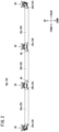
- FIG. 2 is a left side view of the boom 18L.
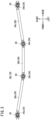
- FIG. 3 is a top view of the boom 18L.
- FIG. 1 referred to in the above description shows the boom 18L with a fairing attached.
- FIGS. 2 and 3 show the boom 18L with the fairing removed.
- FIGS. 2 and 3 also show the boom 18L with four VTOL rotors 20 attached.
- the structure of the boom 18R is identical to that of the boom 18L except that the left and right sides are reversed. Therefore, in this specification, the boom 18L will be described, and the description of the boom 18R will be omitted.
- the boom 18L includes four mounts 24 and three connecting pipes 26 (connecting members).
- the four mounts 24 include a front mount 24a, a first mount 24b, a second mount 24c, and a rear mount 24d.
- the three connecting pipes 26 include a front pipe 26a, an intermediate pipe 26b, and a rear pipe 26c.
- the front mount 24a, the front pipe 26a, the first mount 24b, the intermediate pipe 26b, the second mount 24c, the rear pipe 26c, and the rear mount 24d are connected in this order toward the rear.
- the front pipe 26a when viewed from above, the front pipe 26a extends in a direction rotated clockwise by a predetermined angle with respect to the front-rear direction.
- the front pipe 26a is connected to the front mount 24a and the first mount 24b.
- the front end portion of the front pipe 26a and the front mount 24a are permanently connected.
- the rear end portion of the front pipe 26a and the first mount 24b are permanently connected.
- the left wing 14L of the front wing 14 is connected to the front pipe 26a (see FIG. 1 ).
- the intermediate pipe 26b extends in the front-rear direction.
- the intermediate pipe 26b is connected to the first mount 24b and the second mount 24c.
- the front end portion of the intermediate pipe 26b and the first mount 24b are detachably connected to each other.
- the rear end portion of the intermediate pipe 26b and the second mount 24c are detachably connected to each other.
- the structure of connection between the mount 24 (the first mount 24b and the second mount 24c) and the intermediate pipe 26b will be described later.
- the rear pipe 26c when viewed from above, extends in a direction rotated counterclockwise by a predetermined angle with respect to the front-rear direction.
- the rear pipe 26c is connected to the second mount 24c and the rear mount 24d.
- the front end portion of the rear pipe 26c and the second mount 24c are permanently connected.
- the rear end portion of the rear pipe 26c and the rear mount 24d are permanently connected.
- the left wing 16L of the rear wing 16 is connected to the rear pipe 26c (see FIG. 1 ).
- the four mounts 24 and the three connecting pipes 26 are alternately connected from the front to the rear. Further, the front pipe 26a is supported by the left wing 14L of the front wing 14, and the rear pipe 26c is supported by the left wing 16L of the rear wing 16. As a result, the boom 18L is fixed in the left direction of the fuselage 12.
- FIG. 4 is an enlarged view of the first mount 24b, the VTOL rotor 20, and the peripheral structure thereof shown in FIG. 2 .
- the first mount 24b supports the VTOL rotor 20.
- the VTOL rotor 20 includes a motor 30, a heat sink 32, a gear box 34, a shaft 36, a propeller 38, a variable pitch mechanism 40, a first actuator 44a, and a second actuator 44b.
- the heat sink 32 is attached to the outer periphery of the motor 30.
- the gear box 34 is attached to the upper end portion of the motor 30.
- the shaft 36 extends upward from the gear box 34.
- the propeller 38 is attached to the upper end portion of the shaft 36.
- the variable pitch mechanism 40 adjusts the pitch of blades 42 of the propeller 38.
- the variable pitch mechanism 40 includes a moving member 46.
- the moving member 46 is movable up and down along the shaft 36.
- the moving member 46 is connected to a link mechanism (not shown).
- the link mechanism changes the pitch of each blade 42 according to the movement of the moving member 46.
- the moving member 46 extends in the extension direction of the boom 18L with the shaft 36 as the center.
- the first actuator 44a is connected to the front end portion of the moving member 46.
- the second actuator 44b is connected to the rear end portion of the moving member 46.
- An accommodation hole 50, a first void 52, and a second void 54 are formed in the first mount 24b. Further, a front joint portion 56 is formed at the front end portion of the first mount 24b, and a rear joint portion 58 is formed at the rear end portion of the first mount 24b. Each of the accommodation hole 50, the first void 52, and the second void 54 penetrates in the up-down direction.
- the accommodation hole 50 is located substantially at the center of the first mount 24b in the front-rear direction.
- the VTOL rotor 20 is accommodated in the accommodation hole 50.
- the first void 52 is located between the accommodation hole 50 and the front joint portion 56.
- a first actuator supporting portion 48a for supporting the first actuator 44a is formed in the first void 52.
- the second void 54 is located between the accommodation hole 50 and the rear joint portion 58.
- a second actuator supporting portion 48b for supporting the second actuator 44b is formed in the second void 54.
- the front joint portion 56 protrudes toward the front pipe 26a located on the front side.
- the front joint portion 56 extends in a direction rotated clockwise by a predetermined angle with respect to the front-rear direction.
- the front joint portion 56 is inserted into the rear end portion of the front pipe 26a.
- the front joint portion 56 and the rear end portion of the front pipe 26a are permanently connected.
- the rear joint portion 58 protrudes toward the intermediate pipe 26b located on the rear side.
- the rear joint portion 58 extends in the front-rear direction.
- the rear joint portion 58 is connected to the front end portion of the intermediate pipe 26b and a reinforcing member 60.
- the upper portion of the rear joint portion 58 has a rounded shape (for example, an elliptical shape) when viewed from the rear.
- the lower portion of the rear joint portion 58 has a rectangular shape with rounded corners when viewed from the rear.
- FIG. 5 is an exploded perspective view of a connection portion between the first mount 24b and the intermediate pipe 26b.
- the cross-sectional shape of the intermediate pipe 26b is the same as the cross-sectional shape of the rear joint portion 58. That is, the upper portion of the intermediate pipe 26b has a rounded shape (for example, an elliptical shape) when viewed from the front.
- the lower portion of the intermediate pipe 26b has a rectangular shape with rounded corners when viewed from the front.
- a notch 62 is formed in the lower portion of the front end portion of the intermediate pipe 26b.
- a protruding portion 64 is formed at the upper portion of the front end portion of the intermediate pipe 26b.
- the protruding portion 64 protrudes toward the rear joint portion 58 of the first mount 24b. That is, the protruding portion 64 protrudes forward.
- the inner peripheral shape of the protruding portion 64 is the same as the outer peripheral shape of the upper portion of the rear joint portion 58.
- the maximum width (the width in the left-right direction) of the protruding portion 64 is equal to or less than the width (the width in the left-right direction) of the notch 62.
- the length (the length in the front-rear direction) of the protruding portion 64 is equal to or less than the length (the length in the protruding direction) of the rear joint portion 58.
- the protruding portion 64 of the intermediate pipe 26b is overlapped with the rear joint portion 58 from above (a first direction). As a result, the protruding portion 64 comes into contact with the upper part of the outer peripheral surface of the rear joint portion 58.
- the protruding portion 64 and the rear joint portion 58 are fastened to each other by a plurality of fastening members such as bolts. In this manner, the protruding portion 64 is detachably connected to the rear joint portion 58. In a state in which the protruding portion 64 is connected to the rear joint portion 58, the lower portion of the rear joint portion 58 is disposed in the notch 62.
- the reinforcing member 60 is a bent plate member.
- the cross-sectional shape of the reinforcing member 60 is the same as the cross-sectional shape of the lower portion of the rear joint portion 58 and the cross-sectional shape of the lower portion of the intermediate pipe 26b.
- the reinforcing member 60 is slightly larger than the lower portion of the rear joint portion 58 and the lower portion of the intermediate pipe 26b.
- the width (the width in the left-right direction) of the reinforcing member 60 is slightly larger than the width (the width in the left-right direction) of the rear joint portion 58 and the width (the width in the left-right direction) of the intermediate pipe 26b.
- the length (the length in the front-rear direction) of the reinforcing member 60 is, for example, about twice the length (the length in the protruding direction) of the protruding portion 64.
- the length of the reinforcing member 60 is not limited to this length.
- the reinforcing member 60 may have any length as long as it overlaps the lower portion of the intermediate pipe 26b and the lower portion of the rear joint portion 58 located in the notch 62 in a state where the rear joint portion 58 and the protruding portion 64 of the intermediate pipe 26b are fastened to each other.
- the reinforcing member 60 is overlapped with the rear joint portion 58 and the intermediate pipe 26b from below (a second direction). As a result, the reinforcing member 60 comes into contact with the lower part of the outer peripheral surface of the rear joint portion 58 and the lower part of the outer peripheral surface of the intermediate pipe 26b.
- the reinforcing member 60 and the rear joint portion 58 are fastened to each other by a plurality of fastening members such as bolts. Further, the reinforcing member 60 and the intermediate pipe 26b are fastened to each other by a plurality of fastening members such as bolts. In this manner, the reinforcing member 60 is detachably connected to the rear joint portion 58 and the intermediate pipe 26b.
- the front end portion of the intermediate pipe 26b and the rear joint portion 58 of the first mount 24b are connected to each other.
- the structure of the rear end portion of the intermediate pipe 26b is identical to the structure of the front end portion of the intermediate pipe 26b except that the front and rear sides are reversed.
- the structure of the second mount 24c is identical to the structure of the first mount 24b except that the front and rear sides are reversed. Accordingly, the rear end portion of the intermediate pipe 26b and the front joint portion (not shown) of the second mount 24c are connected in the same manner as the front end portion of the intermediate pipe 26b and the rear joint portion 58 of the first mount 24b.
- the assembly process of the boom 18L is performed, for example, in the following procedure.
- the protruding portion 64 of the front end portion of the intermediate pipe 26b is overlapped with the rear joint portion 58 of the first mount 24b from above.
- the intermediate pipe 26b and the first mount 24b are fastened to each other by a plurality of fastening members.
- the reinforcing member 60 is overlapped with the rear joint portion 58 of the first mount 24b and the intermediate pipe 26b from below.
- the reinforcing member 60 and the first mount 24b are fastened to each other by a plurality of fastening members.
- the reinforcing member 60 and the intermediate pipe 26b are fastened to each other by a plurality of fastening members.
- the intermediate pipe 26b is connected to the first mount 24b.
- the intermediate pipe 26b is also connected to the second mount 24c.
- the boom 18L is disassembled.
- the process of disassembling the boom 18L is performed in the reverse order of the process of assembling the boom 18L.
- the protruding portion 64 of the intermediate pipe 26b may be overlapped with the rear joint portion 58 from a direction other than above (for example, from the left direction). Accordingly, the reinforcing member 60 may be overlapped with the rear joint portion 58 and the intermediate pipe 26b from a direction other than below (for example, from the right direction). However, for the following reason, it is preferable that the protruding portion 64 of the intermediate pipe 26b is overlapped with the rear joint portion 58 from above. That is, in the attaching and detaching process of the reinforcing member 60, the intermediate pipe 26b is supported by the first mount 24b and the second mount 24c. Therefore, according to the above-described configuration, a device for supporting the intermediate pipe 26b is not required in the attaching and detaching process of the reinforcing member 60.
- the number of the mounts 24 may not be four. Further, the number of the connecting pipes 26 may not be three. For example, the number of the mounts 24 may be five, and the number of the connecting pipes 26 may be four. Further, the shape of the boom 18 may not be a shape extending from the front end portion to the rear end portion. For example, the shape of the boom 18 may be annular. In any embodiment, the connecting pipe 26 that is not fixed to the fuselage may be attachable to and detachable from the mount 24.
- first mount 24b and the second mount 24c In order to connect the first mount 24b and the second mount 24c with an ordinary pipe, it is necessary to push open the first mount 24b and the second mount 24c to insert the pipe therein. However, the first mount 24b and the second mount 24c are fixed to the fuselage. For this reason, it is not possible to push open the first mount 24b and the second mount 24c.
- the intermediate pipe 26b is overlapped with the first mount 24b from above, and the reinforcing member 60 is overlapped with the first mount 24b and the intermediate pipe 26b from below, whereby the intermediate pipe 26b and the first mount 24b are connected to each other.
- the intermediate pipe 26b and the second mount 24c are connected to each other in the same manner.
- the intermediate pipe 26b is attachable to and detachable from the first mount 24b and the second mount 24c.
- One reinforcing member 60 is attachable to and detachable from the first mount 24b and the intermediate pipe 26b.
- Another reinforcing member 60 is attachable to and detachable from the second mount 24c and the intermediate pipe 26b.
- first mount 24b and the second mount 24c can be pushed open.
- first mount 24b and the intermediate pipe 26b may be connected to each other in the following procedure, for example.
- the intermediate pipe 26b is disposed in a direction in which the rear joint portion 58 of the first mount 24b extends when viewed from above. Further, the intermediate pipe 26b is disposed such that the notch 62 of the front end portion thereof and the upper portion of the first mount 24b overlap each other when viewed from the left side. From this state, the intermediate pipe 26b is moved toward the first mount 24b. Then, the notch 62 of the front end portion of the intermediate pipe 26b comes into contact with the upper portion of the first mount 24b. The intermediate pipe 26b is then moved downward. As a result, the protruding portion 64 of the front end portion of the intermediate pipe 26b is overlapped with the rear joint portion 58 of the first mount 24b from above. The subsequent procedure is the same as that described above. By the above-described procedure, the positioning of the intermediate pipe 26b with respect to the first mount 24b is facilitated.
- the rotor support device (18, 18L, 18R) that is provided in the aircraft (10) and supports the rotor (20) configured to generate thrust in the vertical direction
- the rotor support device including: the mount (24, 24b, 24c) configured to support the rotor and including the joint portion (56, 58) protruding outward; the connecting member (26, 26b) extending in the protruding direction of the joint portion and detachably connected to the joint portion; and the reinforcing member (60) detachably connected to the joint portion and the connecting member in order to reinforce the connection between the joint portion and the connecting member, wherein the connecting member includes the end portion connected to the joint portion, and the end portion includes the notch (62) and the protruding portion (64) that is formed by forming the notch, the protruding portion is overlapped with a part of the outer peripheral surface of the joint portion, the part being located on the side of the first direction perpendicular to the protruding direction of
- the rotor support structure is easy to assemble and disassemble, and easy to maintain.
- the protruding portion may be overlapped with an upper part of the outer peripheral surface of the joint portion and detachably connected to the joint portion
- the reinforcing member may be overlapped with the connecting member and a lower part of the outer peripheral surface of the joint portion and detachably connected to the joint portion and the connecting member.
- a device for supporting the connecting member is not required in the attaching and detaching process of the reinforcing member.
- the connecting member may be a pipe.
- the rotor support device may further include the first mount (24b) and the second mount (24c) as the mount, and the first reinforcing member and the second reinforcing member as the reinforcing member, the first mount may support the first rotor as the rotor, the second mount may support the second rotor as the rotor, the notch and the protruding portion may be formed at each of the first end portion and the second end portion of the connecting member, the first end portion of the connecting member and the first reinforcing member may be fastened to the joint portion of the first mount, and the second end portion of the connecting member and the second reinforcing member may be fastened to the joint portion of the second mount.
- the rotor support device may further include the second connecting member (26a, 26c) permanently coupled to the mount and connected to the wing (14, 16) of the aircraft.
- the rotor support device may further include the fixed mount (24a, 24d) configured to support a rotor different from the rotor and permanently coupled to the second connecting member.
- the mount may include the void (52, 54) penetrating in the up-down direction.
- the rotor support device may further include the actuator (44a, 44b) configured to change the pitch of each blade (42) of the rotor, and the actuator supporting portion (48a, 48b) configured to support the actuator and disposed inside the void.
- the rotor support device (18, 18L, 18R) that is provided in the aircraft (10) and supports the rotor (20) configured to generate thrust in the vertical direction
- the rotor support device including: the mount (24, 24b, 24c) configured to support the rotor and including the joint portion (56, 58) protruding outward; the connecting member (26, 26b) extending in the protruding direction of the joint portion and detachably connected to the joint portion; and the reinforcing member (60) detachably connected to the joint portion and the connecting member in order to reinforce the connection between the joint portion and the connecting member, wherein the connecting member includes the end portion connected to the joint portion, and the end portion includes the notch (62) and the protruding portion (64) that is formed by forming the notch, the protruding portion is overlapped with the joint portion from the first direction perpendicular to the protruding direction of the joint portion, and is detachably connected to the joint portion, and
- a rotor support device (18) includes: a mount (24 (24b, 24c)) supporting a rotor (20) and including a joint portion (56, 58) protruding outward; a connecting member (26b); and a reinforcing member (60).
- the connecting member includes an end portion connected to the joint portion and including a notch (62) and a protruding portion (64) formed by forming the notch.
- the protruding portion (64) is overlapped with a part of the outer peripheral surface of the joint portion located on the side of a first direction perpendicular to the protruding direction of the joint portion, and is detachably connected to the joint portion.
- the reinforcing member is overlapped with the connecting member and another part of the outer peripheral surface of the joint portion located on the side of a second direction opposite to the first direction, and is detachably connected to the joint portion and the connecting member.
Landscapes
- Engineering & Computer Science (AREA)
- Aviation & Aerospace Engineering (AREA)
- Mechanical Engineering (AREA)
- Structures Of Non-Positive Displacement Pumps (AREA)
- Mutual Connection Of Rods And Tubes (AREA)
Abstract
Description
- The present invention relates to a rotor support device for supporting rotors that generate thrust in a vertical direction.
-
US 2020/0385130 A1 discloses a vertical take-off and landing aircraft that generates thrust in a vertical direction with a plurality of rotors. Vertical take-off and landing aircraft are commonly referred to as VTOL aircraft. The VTOL aircraft ofUS 2020/0385130 A1 includes two rotors on each of the left and right sides of the fuselage. A first rotor of the two rotors is attached to a first support member extending forward of the front wing. A second rotor of the two rotors is attached to a second support member extending from the front wing to the rear wing. - Preferably, the rotor support structure is easy to assemble and disassemble, and easy to maintain.
- An object of the present invention is to solve the above-mentioned problem.
- According to an aspect of the first invention, there is provided a rotor support device that is provided in an aircraft and supports a rotor configured to generate thrust in a vertical direction, the rotor support device comprising: a mount configured to support the rotor and including a joint portion protruding outward; a connecting member extending in a protruding direction of the joint portion and detachably connected to the joint portion; and a reinforcing member detachably connected to the joint portion and the connecting member in order to reinforce connection between the joint portion and the connecting member, wherein the connecting member includes an end portion connected to the joint portion, and the end portion includes a notch and a protruding portion that is formed by forming the notch, the protruding portion is overlapped with a part of an outer peripheral surface of the joint portion, the part being located on a side of a first direction perpendicular to the protruding direction of the joint portion, and is detachably connected to the joint portion, and the reinforcing member is overlapped with the connecting member and another part of the outer peripheral surface of the joint portion, the another part being located on a side of a second direction opposite to the first direction, and is detachably connected to the joint portion and the connecting member.
- According to an aspect of the second invention, there is provided a rotor support device that is provided in an aircraft and supports a rotor configured to generate thrust in a vertical direction, the rotor support device comprising: a mount configured to support the rotor and including a joint portion protruding outward; a connecting member extending in a protruding direction of the joint portion and detachably connected to the joint portion; and a reinforcing member detachably connected to the joint portion and the connecting member in order to reinforce connection between the joint portion and the connecting member, wherein the connecting member includes an end portion connected to the joint portion, and the end portion includes a notch and a protruding portion that is formed by forming the notch, the protruding portion is overlapped with the joint portion from a first direction perpendicular to the protruding direction of the joint portion, and is detachably connected to the joint portion, and the reinforcing member is overlapped with the joint portion and the connecting member from a second direction that is opposite to the first direction, and is detachably connected to the joint portion and the connecting member.
- According to the present invention, the rotor support structure is easy to assemble and disassemble, and easy to maintain.
- The above and other objects, features, and advantages of the present invention will become more apparent from the following description when taken in conjunction with the accompanying drawings, in which a preferred embodiment of the present invention is shown by way of illustrative example.
-
-
FIG. 1 is an external view of a VTOL aircraft; -
FIG. 2 is a left side view of a boom; -
FIG. 3 is a top view of the boom; -
FIG. 4 is an enlarged view of a first mount, a VTOL rotor, and the peripheral structure thereof shown inFIG. 2 ; and -
FIG. 5 is an exploded perspective view of a connection portion between the first mount and an intermediate pipe. -
FIG. 1 is an external view of aVTOL aircraft 10. The VTOLaircraft 10 is, for example, an electric vertical take-off and landing aircraft, a so-called eVTOL aircraft. The VTOLaircraft 10 includes afuselage 12, afront wing 14, arear wing 16, twobooms 18, eightVTOL rotors 20, and twocruise rotors 22. - The
front wing 14 is connected to a front portion of thefuselage 12. Thefront wing 14 includes aleft wing 14L and aright wing 14R. Therear wing 16 is connected to a rear portion of thefuselage 12. Therear wing 16 includes aleft wing 16L and aright wing 16R. Thefront wing 14 and therear wing 16 generate lift as the VTOLaircraft 10 moves forward. - Each of the two
booms 18 is a rotor support device that supports fourVTOL rotors 20. Aboom 18R of the twobooms 18 is disposed on the right side of thefuselage 12. Aboom 18L of the twobooms 18 is disposed on the left side of thefuselage 12. Eachboom 18 extends in the front-rear direction. - Four
VTOL rotors 20 are arranged on theboom 18L sequentially toward the rear. Similarly, fourVTOL rotors 20 are arranged on theboom 18R sequentially toward the rear. EachVTOL rotor 20 generates thrust in the vertical direction. - Two
cruise rotors 22 are disposed on therear wing 16 so as to be arranged side by side in the left-right direction. Eachcruise rotor 22 generates thrust in the horizontal direction. -
FIG. 2 is a left side view of theboom 18L.FIG. 3 is a top view of theboom 18L. Note thatFIG. 1 referred to in the above description shows theboom 18L with a fairing attached. On the other hand,FIGS. 2 and3 show theboom 18L with the fairing removed.FIGS. 2 and3 also show theboom 18L with fourVTOL rotors 20 attached. The structure of theboom 18R is identical to that of theboom 18L except that the left and right sides are reversed. Therefore, in this specification, theboom 18L will be described, and the description of theboom 18R will be omitted. - The
boom 18L includes fourmounts 24 and three connecting pipes 26 (connecting members). The fourmounts 24 include afront mount 24a, afirst mount 24b, asecond mount 24c, and arear mount 24d. The three connectingpipes 26 include afront pipe 26a, anintermediate pipe 26b, and arear pipe 26c. Thefront mount 24a, thefront pipe 26a, thefirst mount 24b, theintermediate pipe 26b, thesecond mount 24c, therear pipe 26c, and therear mount 24d are connected in this order toward the rear. - As shown in
FIG. 3 , when viewed from above, thefront pipe 26a extends in a direction rotated clockwise by a predetermined angle with respect to the front-rear direction. Thefront pipe 26a is connected to thefront mount 24a and thefirst mount 24b. The front end portion of thefront pipe 26a and thefront mount 24a are permanently connected. The rear end portion of thefront pipe 26a and thefirst mount 24b are permanently connected. Further, theleft wing 14L of thefront wing 14 is connected to thefront pipe 26a (seeFIG. 1 ). - The
intermediate pipe 26b extends in the front-rear direction. Theintermediate pipe 26b is connected to thefirst mount 24b and thesecond mount 24c. The front end portion of theintermediate pipe 26b and thefirst mount 24b are detachably connected to each other. The rear end portion of theintermediate pipe 26b and thesecond mount 24c are detachably connected to each other. The structure of connection between the mount 24 (thefirst mount 24b and thesecond mount 24c) and theintermediate pipe 26b will be described later. - As shown in
FIG. 3 , when viewed from above, therear pipe 26c extends in a direction rotated counterclockwise by a predetermined angle with respect to the front-rear direction. Therear pipe 26c is connected to thesecond mount 24c and therear mount 24d. The front end portion of therear pipe 26c and thesecond mount 24c are permanently connected. The rear end portion of therear pipe 26c and therear mount 24d are permanently connected. Further, theleft wing 16L of therear wing 16 is connected to therear pipe 26c (seeFIG. 1 ). - As described above, the four mounts 24 and the three connecting
pipes 26 are alternately connected from the front to the rear. Further, thefront pipe 26a is supported by theleft wing 14L of thefront wing 14, and therear pipe 26c is supported by theleft wing 16L of therear wing 16. As a result, theboom 18L is fixed in the left direction of thefuselage 12. -
FIG. 4 is an enlarged view of thefirst mount 24b, theVTOL rotor 20, and the peripheral structure thereof shown inFIG. 2 . Thefirst mount 24b supports theVTOL rotor 20. TheVTOL rotor 20 includes amotor 30, aheat sink 32, agear box 34, ashaft 36, apropeller 38, avariable pitch mechanism 40, afirst actuator 44a, and asecond actuator 44b. Theheat sink 32 is attached to the outer periphery of themotor 30. Thegear box 34 is attached to the upper end portion of themotor 30. Theshaft 36 extends upward from thegear box 34. Thepropeller 38 is attached to the upper end portion of theshaft 36. - The
variable pitch mechanism 40 adjusts the pitch ofblades 42 of thepropeller 38. Thevariable pitch mechanism 40 includes a movingmember 46. The movingmember 46 is movable up and down along theshaft 36. The movingmember 46 is connected to a link mechanism (not shown). The link mechanism changes the pitch of eachblade 42 according to the movement of the movingmember 46. As shown inFIG. 4 , the movingmember 46 extends in the extension direction of theboom 18L with theshaft 36 as the center. Thefirst actuator 44a is connected to the front end portion of the movingmember 46. Thesecond actuator 44b is connected to the rear end portion of the movingmember 46. - An
accommodation hole 50, afirst void 52, and asecond void 54 are formed in thefirst mount 24b. Further, a frontjoint portion 56 is formed at the front end portion of thefirst mount 24b, and a rearjoint portion 58 is formed at the rear end portion of thefirst mount 24b. Each of theaccommodation hole 50, thefirst void 52, and thesecond void 54 penetrates in the up-down direction. - The
accommodation hole 50 is located substantially at the center of thefirst mount 24b in the front-rear direction. TheVTOL rotor 20 is accommodated in theaccommodation hole 50. Thefirst void 52 is located between theaccommodation hole 50 and the frontjoint portion 56. A firstactuator supporting portion 48a for supporting thefirst actuator 44a is formed in thefirst void 52. Thesecond void 54 is located between theaccommodation hole 50 and the rearjoint portion 58. A secondactuator supporting portion 48b for supporting thesecond actuator 44b is formed in thesecond void 54. - The front
joint portion 56 protrudes toward thefront pipe 26a located on the front side. The frontjoint portion 56 extends in a direction rotated clockwise by a predetermined angle with respect to the front-rear direction. The frontjoint portion 56 is inserted into the rear end portion of thefront pipe 26a. The frontjoint portion 56 and the rear end portion of thefront pipe 26a are permanently connected. - The rear
joint portion 58 protrudes toward theintermediate pipe 26b located on the rear side. The rearjoint portion 58 extends in the front-rear direction. The rearjoint portion 58 is connected to the front end portion of theintermediate pipe 26b and a reinforcingmember 60. The upper portion of the rearjoint portion 58 has a rounded shape (for example, an elliptical shape) when viewed from the rear. The lower portion of the rearjoint portion 58 has a rectangular shape with rounded corners when viewed from the rear. -
FIG. 5 is an exploded perspective view of a connection portion between thefirst mount 24b and theintermediate pipe 26b. The cross-sectional shape of theintermediate pipe 26b is the same as the cross-sectional shape of the rearjoint portion 58. That is, the upper portion of theintermediate pipe 26b has a rounded shape (for example, an elliptical shape) when viewed from the front. The lower portion of theintermediate pipe 26b has a rectangular shape with rounded corners when viewed from the front. Anotch 62 is formed in the lower portion of the front end portion of theintermediate pipe 26b. As a result, a protrudingportion 64 is formed at the upper portion of the front end portion of theintermediate pipe 26b. - The protruding
portion 64 protrudes toward the rearjoint portion 58 of thefirst mount 24b. That is, the protrudingportion 64 protrudes forward. The inner peripheral shape of the protrudingportion 64 is the same as the outer peripheral shape of the upper portion of the rearjoint portion 58. The maximum width (the width in the left-right direction) of the protrudingportion 64 is equal to or less than the width (the width in the left-right direction) of thenotch 62. The length (the length in the front-rear direction) of the protrudingportion 64 is equal to or less than the length (the length in the protruding direction) of the rearjoint portion 58. - As indicated by an arrow A in
FIG. 5 , the protrudingportion 64 of theintermediate pipe 26b is overlapped with the rearjoint portion 58 from above (a first direction). As a result, the protrudingportion 64 comes into contact with the upper part of the outer peripheral surface of the rearjoint portion 58. The protrudingportion 64 and the rearjoint portion 58 are fastened to each other by a plurality of fastening members such as bolts. In this manner, the protrudingportion 64 is detachably connected to the rearjoint portion 58. In a state in which the protrudingportion 64 is connected to the rearjoint portion 58, the lower portion of the rearjoint portion 58 is disposed in thenotch 62. - The reinforcing
member 60 is a bent plate member. The cross-sectional shape of the reinforcingmember 60 is the same as the cross-sectional shape of the lower portion of the rearjoint portion 58 and the cross-sectional shape of the lower portion of theintermediate pipe 26b. However, the reinforcingmember 60 is slightly larger than the lower portion of the rearjoint portion 58 and the lower portion of theintermediate pipe 26b. In other words, the width (the width in the left-right direction) of the reinforcingmember 60 is slightly larger than the width (the width in the left-right direction) of the rearjoint portion 58 and the width (the width in the left-right direction) of theintermediate pipe 26b. The length (the length in the front-rear direction) of the reinforcingmember 60 is, for example, about twice the length (the length in the protruding direction) of the protrudingportion 64. However, the length of the reinforcingmember 60 is not limited to this length. The reinforcingmember 60 may have any length as long as it overlaps the lower portion of theintermediate pipe 26b and the lower portion of the rearjoint portion 58 located in thenotch 62 in a state where the rearjoint portion 58 and the protrudingportion 64 of theintermediate pipe 26b are fastened to each other. - As indicated by an arrow B in
FIG. 5 , the reinforcingmember 60 is overlapped with the rearjoint portion 58 and theintermediate pipe 26b from below (a second direction). As a result, the reinforcingmember 60 comes into contact with the lower part of the outer peripheral surface of the rearjoint portion 58 and the lower part of the outer peripheral surface of theintermediate pipe 26b. The reinforcingmember 60 and the rearjoint portion 58 are fastened to each other by a plurality of fastening members such as bolts. Further, the reinforcingmember 60 and theintermediate pipe 26b are fastened to each other by a plurality of fastening members such as bolts. In this manner, the reinforcingmember 60 is detachably connected to the rearjoint portion 58 and theintermediate pipe 26b. - As described above, the front end portion of the
intermediate pipe 26b and the rearjoint portion 58 of thefirst mount 24b are connected to each other. The structure of the rear end portion of theintermediate pipe 26b is identical to the structure of the front end portion of theintermediate pipe 26b except that the front and rear sides are reversed. In addition, the structure of thesecond mount 24c is identical to the structure of thefirst mount 24b except that the front and rear sides are reversed. Accordingly, the rear end portion of theintermediate pipe 26b and the front joint portion (not shown) of thesecond mount 24c are connected in the same manner as the front end portion of theintermediate pipe 26b and the rearjoint portion 58 of thefirst mount 24b. - The assembly process of the
boom 18L is performed, for example, in the following procedure. First, thefront pipe 26a to which thefront mount 24a and thefirst mount 24b are connected is connected to thefront wing 14. Further, therear pipe 26c to which thesecond mount 24c and therear mount 24d are connected is connected to therear wing 16. In this manner, thefront pipe 26a and therear pipe 26c are connected to the fuselage in advance. Therefore, each of thefirst mount 24b and thesecond mount 24c is positioned. - In this state, the protruding
portion 64 of the front end portion of theintermediate pipe 26b is overlapped with the rearjoint portion 58 of thefirst mount 24b from above. Theintermediate pipe 26b and thefirst mount 24b are fastened to each other by a plurality of fastening members. Next, the reinforcingmember 60 is overlapped with the rearjoint portion 58 of thefirst mount 24b and theintermediate pipe 26b from below. The reinforcingmember 60 and thefirst mount 24b are fastened to each other by a plurality of fastening members. Further, the reinforcingmember 60 and theintermediate pipe 26b are fastened to each other by a plurality of fastening members. Thus, theintermediate pipe 26b is connected to thefirst mount 24b. Similarly, theintermediate pipe 26b is also connected to thesecond mount 24c. As a result, the basic part of theboom 18L is completed. - In the maintenance of the
boom 18L, theboom 18L is disassembled. The process of disassembling theboom 18L is performed in the reverse order of the process of assembling theboom 18L. - The protruding
portion 64 of theintermediate pipe 26b may be overlapped with the rearjoint portion 58 from a direction other than above (for example, from the left direction). Accordingly, the reinforcingmember 60 may be overlapped with the rearjoint portion 58 and theintermediate pipe 26b from a direction other than below (for example, from the right direction). However, for the following reason, it is preferable that the protrudingportion 64 of theintermediate pipe 26b is overlapped with the rearjoint portion 58 from above. That is, in the attaching and detaching process of the reinforcingmember 60, theintermediate pipe 26b is supported by thefirst mount 24b and thesecond mount 24c. Therefore, according to the above-described configuration, a device for supporting theintermediate pipe 26b is not required in the attaching and detaching process of the reinforcingmember 60. - The number of the
mounts 24 may not be four. Further, the number of the connectingpipes 26 may not be three. For example, the number of themounts 24 may be five, and the number of the connectingpipes 26 may be four. Further, the shape of theboom 18 may not be a shape extending from the front end portion to the rear end portion. For example, the shape of theboom 18 may be annular. In any embodiment, the connectingpipe 26 that is not fixed to the fuselage may be attachable to and detachable from themount 24. - In order to connect the
first mount 24b and thesecond mount 24c with an ordinary pipe, it is necessary to push open thefirst mount 24b and thesecond mount 24c to insert the pipe therein. However, thefirst mount 24b and thesecond mount 24c are fixed to the fuselage. For this reason, it is not possible to push open thefirst mount 24b and thesecond mount 24c. - In the present embodiment, the
intermediate pipe 26b is overlapped with thefirst mount 24b from above, and the reinforcingmember 60 is overlapped with thefirst mount 24b and theintermediate pipe 26b from below, whereby theintermediate pipe 26b and thefirst mount 24b are connected to each other. Theintermediate pipe 26b and thesecond mount 24c are connected to each other in the same manner. Further, theintermediate pipe 26b is attachable to and detachable from thefirst mount 24b and thesecond mount 24c. One reinforcingmember 60 is attachable to and detachable from thefirst mount 24b and theintermediate pipe 26b. Another reinforcingmember 60 is attachable to and detachable from thesecond mount 24c and theintermediate pipe 26b. In the present embodiment, it is not necessary to push open thefirst mount 24b and thesecond mount 24c. Therefore, according to the present embodiment, the rotor support structure is easy to assemble and disassemble, and easy to maintain. - Note that there is a model in which the
first mount 24b and thesecond mount 24c can be pushed open. In the case of such a model, thefirst mount 24b and theintermediate pipe 26b may be connected to each other in the following procedure, for example. - The
intermediate pipe 26b is disposed in a direction in which the rearjoint portion 58 of thefirst mount 24b extends when viewed from above. Further, theintermediate pipe 26b is disposed such that thenotch 62 of the front end portion thereof and the upper portion of thefirst mount 24b overlap each other when viewed from the left side. From this state, theintermediate pipe 26b is moved toward thefirst mount 24b. Then, thenotch 62 of the front end portion of theintermediate pipe 26b comes into contact with the upper portion of thefirst mount 24b. Theintermediate pipe 26b is then moved downward. As a result, the protrudingportion 64 of the front end portion of theintermediate pipe 26b is overlapped with the rearjoint portion 58 of thefirst mount 24b from above. The subsequent procedure is the same as that described above. By the above-described procedure, the positioning of theintermediate pipe 26b with respect to thefirst mount 24b is facilitated. - The inventions that can be grasped from the above embodiments will be described below.
- According to an aspect of the first invention, provided is the rotor support device (18, 18L, 18R) that is provided in the aircraft (10) and supports the rotor (20) configured to generate thrust in the vertical direction, the rotor support device including: the mount (24, 24b, 24c) configured to support the rotor and including the joint portion (56, 58) protruding outward; the connecting member (26, 26b) extending in the protruding direction of the joint portion and detachably connected to the joint portion; and the reinforcing member (60) detachably connected to the joint portion and the connecting member in order to reinforce the connection between the joint portion and the connecting member, wherein the connecting member includes the end portion connected to the joint portion, and the end portion includes the notch (62) and the protruding portion (64) that is formed by forming the notch, the protruding portion is overlapped with a part of the outer peripheral surface of the joint portion, the part being located on the side of the first direction perpendicular to the protruding direction of the joint portion, and is detachably connected to the joint portion, and the reinforcing member is overlapped with the connecting member and another part of the outer peripheral surface of the joint portion, the another part being located on the side of the second direction opposite to the first direction, and is detachably connected to the joint portion and the connecting member.
- According to the above configuration, the rotor support structure is easy to assemble and disassemble, and easy to maintain.
- In the above aspect, the protruding portion may be overlapped with an upper part of the outer peripheral surface of the joint portion and detachably connected to the joint portion, and the reinforcing member may be overlapped with the connecting member and a lower part of the outer peripheral surface of the joint portion and detachably connected to the joint portion and the connecting member.
- According to the above configuration, a device for supporting the connecting member is not required in the attaching and detaching process of the reinforcing member.
- In the above aspect, the connecting member may be a pipe.
- In the above aspect, the rotor support device may further include the first mount (24b) and the second mount (24c) as the mount, and the first reinforcing member and the second reinforcing member as the reinforcing member, the first mount may support the first rotor as the rotor, the second mount may support the second rotor as the rotor, the notch and the protruding portion may be formed at each of the first end portion and the second end portion of the connecting member, the first end portion of the connecting member and the first reinforcing member may be fastened to the joint portion of the first mount, and the second end portion of the connecting member and the second reinforcing member may be fastened to the joint portion of the second mount.
- In the above aspect, the rotor support device may further include the second connecting member (26a, 26c) permanently coupled to the mount and connected to the wing (14, 16) of the aircraft.
- In the above aspect, the rotor support device may further include the fixed mount (24a, 24d) configured to support a rotor different from the rotor and permanently coupled to the second connecting member.
- In the above aspect, the mount may include the void (52, 54) penetrating in the up-down direction.
- In the above aspect, the rotor support device may further include the actuator (44a, 44b) configured to change the pitch of each blade (42) of the rotor, and the actuator supporting portion (48a, 48b) configured to support the actuator and disposed inside the void.
- According to an aspect of the second invention, provided is the rotor support device (18, 18L, 18R) that is provided in the aircraft (10) and supports the rotor (20) configured to generate thrust in the vertical direction, the rotor support device including: the mount (24, 24b, 24c) configured to support the rotor and including the joint portion (56, 58) protruding outward; the connecting member (26, 26b) extending in the protruding direction of the joint portion and detachably connected to the joint portion; and the reinforcing member (60) detachably connected to the joint portion and the connecting member in order to reinforce the connection between the joint portion and the connecting member, wherein the connecting member includes the end portion connected to the joint portion, and the end portion includes the notch (62) and the protruding portion (64) that is formed by forming the notch, the protruding portion is overlapped with the joint portion from the first direction perpendicular to the protruding direction of the joint portion, and is detachably connected to the joint portion, and the reinforcing member is overlapped with the joint portion and the connecting member from the second direction that is opposite to the first direction, and is detachably connected to the joint portion and the connecting member.
- A rotor support device (18) includes: a mount (24 (24b, 24c)) supporting a rotor (20) and including a joint portion (56, 58) protruding outward; a connecting member (26b); and a reinforcing member (60). The connecting member includes an end portion connected to the joint portion and including a notch (62) and a protruding portion (64) formed by forming the notch. The protruding portion (64) is overlapped with a part of the outer peripheral surface of the joint portion located on the side of a first direction perpendicular to the protruding direction of the joint portion, and is detachably connected to the joint portion. The reinforcing member is overlapped with the connecting member and another part of the outer peripheral surface of the joint portion located on the side of a second direction opposite to the first direction, and is detachably connected to the joint portion and the connecting member.
Claims (9)
- A rotor support device (18) that is provided in an aircraft (10) and supports a rotor (20) configured to generate thrust in a vertical direction, the rotor support device comprising:a mount (24) configured to support the rotor and including a joint portion (56, 58) protruding outward;a connecting member (26) extending in a protruding direction of the joint portion and detachably connected to the joint portion; anda reinforcing member (60) detachably connected to the joint portion and the connecting member in order to reinforce connection between the joint portion and the connecting member,wherein the connecting member includes an end portion connected to the joint portion, and the end portion includes a notch (62) and a protruding portion (64) that is formed by forming the notch,the protruding portion is overlapped with a part of an outer peripheral surface of the joint portion, the part being located on a side of a first direction perpendicular to the protruding direction of the joint portion, and is detachably connected to the joint portion, andthe reinforcing member is overlapped with the connecting member and another part of the outer peripheral surface of the joint portion, the another part being located on a side of a second direction opposite to the first direction, and is detachably connected to the joint portion and the connecting member.
- The rotor support device according to claim 1, whereinthe protruding portion is overlapped with an upper part of the outer peripheral surface of the joint portion, and is detachably connected to the joint portion, andthe reinforcing member is overlapped with the connecting member and a lower part of the outer peripheral surface of the joint portion, and is detachably connected to the joint portion and the connecting member.
- The rotor support device according to claim 1 or 2,
wherein
the connecting member is a pipe. - The rotor support device according to claim 3, further comprising:a first mount (24b) and a second mount (24c) as the mount; anda first reinforcing member and a second reinforcing member as the reinforcing member,wherein the first mount supports a first rotor as the rotor,the second mount supports a second rotor as the rotor,the notch and the protruding portion are formed at each of a first end portion and a second end portion of the connecting member,the first end portion of the connecting member and the first reinforcing member are fastened to the joint portion of the first mount, andthe second end portion of the connecting member and the second reinforcing member are fastened to the joint portion of the second mount.
- The rotor support device according to claim 1 or 2, further comprising a second connecting member (26a, 26c) permanently coupled to the mount and connected to a wing (14, 16) of the aircraft.
- The rotor support device according to claim 5, further comprising a fixed mount (24a, 24d) configured to support a rotor different from the rotor and permanently coupled to the second connecting member.
- The rotor support device according to claim 1 or 2,
wherein
the mount includes a void (52, 54) penetrating in an up-down direction. - The rotor support device according to claim 7, further comprising:an actuator (44a, 44b) configured to change a pitch of each blade (42) of the rotor; andan actuator supporting portion (48a, 48b) configured to support the actuator and disposed inside the void.
- A rotor support device that is provided in an aircraft and supports a rotor configured to generate thrust in a vertical direction, the rotor support device comprising:a mount configured to support the rotor and including a joint portion protruding outward;a connecting member extending in a protruding direction of the joint portion and detachably connected to the joint portion; anda reinforcing member detachably connected to the joint portion and the connecting member in order to reinforce connection between the joint portion and the connecting member,wherein the connecting member includes an end portion connected to the joint portion, and the end portion includes a notch and a protruding portion that is formed by forming the notch,the protruding portion is overlapped with the joint portion from a first direction perpendicular to the protruding direction of the joint portion, and is detachably connected to the joint portion, andthe reinforcing member is overlapped with the joint portion and the connecting member from a second direction that is opposite to the first direction, and is detachably connected to the joint portion and the connecting member.
Applications Claiming Priority (1)
| Application Number | Priority Date | Filing Date | Title |
|---|---|---|---|
| JP2022139603A JP7819062B2 (en) | 2022-09-02 | 2022-09-02 | Rotor Support Device |
Publications (2)
| Publication Number | Publication Date |
|---|---|
| EP4331979A1 true EP4331979A1 (en) | 2024-03-06 |
| EP4331979B1 EP4331979B1 (en) | 2025-04-16 |
Family
ID=87889355
Family Applications (1)
| Application Number | Title | Priority Date | Filing Date |
|---|---|---|---|
| EP23194711.0A Active EP4331979B1 (en) | 2022-09-02 | 2023-08-31 | Rotor support device |
Country Status (4)
| Country | Link |
|---|---|
| US (1) | US12269587B2 (en) |
| EP (1) | EP4331979B1 (en) |
| JP (1) | JP7819062B2 (en) |
| CN (1) | CN117644971A (en) |
Citations (6)
| Publication number | Priority date | Publication date | Assignee | Title |
|---|---|---|---|---|
| CN205168884U (en) * | 2015-11-26 | 2016-04-20 | 北京浩恒征途航空科技有限公司 | Many rotor crafts and actuating mechanism mount pad thereof |
| WO2017166275A1 (en) * | 2016-04-01 | 2017-10-05 | 深圳市大疆创新科技有限公司 | Airframe connection components for unmanned aerial vehicle, and unmanned aerial vehicle |
| CN209553498U (en) * | 2019-02-13 | 2019-10-29 | 深圳创壹通航科技有限公司 | Fixed-wing unmanned plane with VTOL function |
| US20200385130A1 (en) | 2019-06-06 | 2020-12-10 | Beta Air, Llc | Integrated electric propulsion assembly |
| US20210107640A1 (en) * | 2019-08-16 | 2021-04-15 | Textron Systems Corporation | Separated lift-thrust vtol aircraft with articulated rotors |
| WO2022130501A1 (en) * | 2020-12-15 | 2022-06-23 | 本田技研工業株式会社 | Aircraft |
Family Cites Families (7)
| Publication number | Priority date | Publication date | Assignee | Title |
|---|---|---|---|---|
| JP3410304B2 (en) * | 1996-10-15 | 2003-05-26 | ヤマハ発動機株式会社 | Industrial unmanned helicopter |
| FR2911320B1 (en) * | 2007-01-16 | 2009-04-10 | Sagem Defense Securite | AIRCRAFT VESSEL IN MULTIPLE DETACHABLE ELEMENTS |
| CN206171788U (en) * | 2016-10-27 | 2017-05-17 | 深圳市大疆创新科技有限公司 | Unmanned aerial vehicle |
| US11312492B1 (en) * | 2017-11-09 | 2022-04-26 | Hood Technology Corporation | Rotorcraft-assisted systems and methods for launching and retrieving a fixed-wing aircraft into and from free flight |
| WO2019204932A1 (en) * | 2018-04-25 | 2019-10-31 | Flir Unmanned Aerial Systems Ulc | Unmanned vehicle |
| KR102481778B1 (en) * | 2020-07-07 | 2022-12-27 | 주식회사 유라 | Protective Cap |
| CN114671006B (en) * | 2022-04-15 | 2024-09-06 | 上海新云彩航空科技有限责任公司 | Aircraft rotor wing support arm folding mechanism and aircraft rotor wing support arm |
-
2022
- 2022-09-02 JP JP2022139603A patent/JP7819062B2/en active Active
-
2023
- 2023-08-29 US US18/457,837 patent/US12269587B2/en active Active
- 2023-08-31 EP EP23194711.0A patent/EP4331979B1/en active Active
- 2023-09-01 CN CN202311124085.XA patent/CN117644971A/en active Pending
Patent Citations (6)
| Publication number | Priority date | Publication date | Assignee | Title |
|---|---|---|---|---|
| CN205168884U (en) * | 2015-11-26 | 2016-04-20 | 北京浩恒征途航空科技有限公司 | Many rotor crafts and actuating mechanism mount pad thereof |
| WO2017166275A1 (en) * | 2016-04-01 | 2017-10-05 | 深圳市大疆创新科技有限公司 | Airframe connection components for unmanned aerial vehicle, and unmanned aerial vehicle |
| CN209553498U (en) * | 2019-02-13 | 2019-10-29 | 深圳创壹通航科技有限公司 | Fixed-wing unmanned plane with VTOL function |
| US20200385130A1 (en) | 2019-06-06 | 2020-12-10 | Beta Air, Llc | Integrated electric propulsion assembly |
| US20210107640A1 (en) * | 2019-08-16 | 2021-04-15 | Textron Systems Corporation | Separated lift-thrust vtol aircraft with articulated rotors |
| WO2022130501A1 (en) * | 2020-12-15 | 2022-06-23 | 本田技研工業株式会社 | Aircraft |
Also Published As
| Publication number | Publication date |
|---|---|
| JP2024035257A (en) | 2024-03-14 |
| CN117644971A (en) | 2024-03-05 |
| US20240076031A1 (en) | 2024-03-07 |
| EP4331979B1 (en) | 2025-04-16 |
| JP7819062B2 (en) | 2026-02-24 |
| US12269587B2 (en) | 2025-04-08 |
Similar Documents
| Publication | Publication Date | Title |
|---|---|---|
| EP3114030B1 (en) | Engine pylon structure | |
| EP2933187B1 (en) | Rotary wing aircraft with a multiple beam tail boom | |
| US7963479B2 (en) | Method for fixing an engine strut to an airplane wing | |
| CN101484357B (en) | Aircraft engine attachment device comprising two thrust-reacting link rods that fit together transversely | |
| JP5421263B2 (en) | Aircraft engine mounting device with compact design thrust force take-up device | |
| CN102971213B (en) | The control method of alighting gear frame cabin door and the hatch door of enforcement | |
| US9212607B2 (en) | Intermediate structure for independently de-mountable propulsion components | |
| JP4676982B2 (en) | Aircraft engine unit | |
| EP2234879B1 (en) | Split pivot fitting for helicopter landing gear | |
| EP3650341A1 (en) | A compound helicopter with a fixed wing arrangement | |
| US20190389555A1 (en) | Aircraft module of a design that makes it easier to assemble in an interior space defined by the fuselage of the aircraft | |
| EP4331979B1 (en) | Rotor support device | |
| CN114013642B (en) | A vertical take-off and landing fixed-wing UAV | |
| EP3077284B1 (en) | Rotor shaft closeout plate | |
| US12545403B2 (en) | Inverted V-tail stabilizer assembly for an aircraft | |
| RU2855022C1 (en) | Helicopter of modular construction | |
| EP4316981A1 (en) | Commonly manufactured rotor blade | |
| US20260116579A1 (en) | Strap Pack Support Tool for Helicopter Maintenance | |
| WO2025233619A1 (en) | Modular aircraft structural support | |
| KR20250165943A (en) | Lightweight fixed wing drone | |
| CN113148106A (en) | Modularized replaceable tail wing | |
| CN111891332A (en) | UAV body and its multi-rotor UAV | |
| CN113232871A (en) | A vaulting pole and aircraft for installing rotor | |
| CN112455675A (en) | Modularized water unmanned aerial vehicle |
Legal Events
| Date | Code | Title | Description |
|---|---|---|---|
| PUAI | Public reference made under article 153(3) epc to a published international application that has entered the european phase |
Free format text: ORIGINAL CODE: 0009012 |
|
| STAA | Information on the status of an ep patent application or granted ep patent |
Free format text: STATUS: REQUEST FOR EXAMINATION WAS MADE |
|
| 17P | Request for examination filed |
Effective date: 20230831 |
|
| AK | Designated contracting states |
Kind code of ref document: A1 Designated state(s): AL AT BE BG CH CY CZ DE DK EE ES FI FR GB GR HR HU IE IS IT LI LT LU LV MC ME MK MT NL NO PL PT RO RS SE SI SK SM TR |
|
| GRAP | Despatch of communication of intention to grant a patent |
Free format text: ORIGINAL CODE: EPIDOSNIGR1 |
|
| STAA | Information on the status of an ep patent application or granted ep patent |
Free format text: STATUS: GRANT OF PATENT IS INTENDED |
|
| RIC1 | Information provided on ipc code assigned before grant |
Ipc: B64C 29/00 20060101ALI20241023BHEP Ipc: B64C 27/54 20060101ALI20241023BHEP Ipc: B64C 27/32 20060101ALI20241023BHEP Ipc: B64C 27/26 20060101ALI20241023BHEP Ipc: B64C 27/08 20230101AFI20241023BHEP |
|
| INTG | Intention to grant announced |
Effective date: 20241112 |
|
| GRAS | Grant fee paid |
Free format text: ORIGINAL CODE: EPIDOSNIGR3 |
|
| GRAA | (expected) grant |
Free format text: ORIGINAL CODE: 0009210 |
|
| STAA | Information on the status of an ep patent application or granted ep patent |
Free format text: STATUS: THE PATENT HAS BEEN GRANTED |
|
| AK | Designated contracting states |
Kind code of ref document: B1 Designated state(s): AL AT BE BG CH CY CZ DE DK EE ES FI FR GB GR HR HU IE IS IT LI LT LU LV MC ME MK MT NL NO PL PT RO RS SE SI SK SM TR |
|
| REG | Reference to a national code |
Ref country code: GB Ref legal event code: FG4D |
|
| REG | Reference to a national code |
Ref country code: CH Ref legal event code: EP Ref country code: DE Ref legal event code: R096 Ref document number: 602023002937 Country of ref document: DE |
|
| REG | Reference to a national code |
Ref country code: IE Ref legal event code: FG4D |
|
| RAP4 | Party data changed (patent owner data changed or rights of a patent transferred) |
Owner name: HONDA MOTOR CO., LTD. |
|
| REG | Reference to a national code |
Ref country code: NL Ref legal event code: MP Effective date: 20250416 |
|
| PG25 | Lapsed in a contracting state [announced via postgrant information from national office to epo] |
Ref country code: NL Free format text: LAPSE BECAUSE OF FAILURE TO SUBMIT A TRANSLATION OF THE DESCRIPTION OR TO PAY THE FEE WITHIN THE PRESCRIBED TIME-LIMIT Effective date: 20250416 |
|
| REG | Reference to a national code |
Ref country code: AT Ref legal event code: MK05 Ref document number: 1785470 Country of ref document: AT Kind code of ref document: T Effective date: 20250416 |
|
| PG25 | Lapsed in a contracting state [announced via postgrant information from national office to epo] |
Ref country code: FI Free format text: LAPSE BECAUSE OF FAILURE TO SUBMIT A TRANSLATION OF THE DESCRIPTION OR TO PAY THE FEE WITHIN THE PRESCRIBED TIME-LIMIT Effective date: 20250416 Ref country code: ES Free format text: LAPSE BECAUSE OF FAILURE TO SUBMIT A TRANSLATION OF THE DESCRIPTION OR TO PAY THE FEE WITHIN THE PRESCRIBED TIME-LIMIT Effective date: 20250416 Ref country code: PT Free format text: LAPSE BECAUSE OF FAILURE TO SUBMIT A TRANSLATION OF THE DESCRIPTION OR TO PAY THE FEE WITHIN THE PRESCRIBED TIME-LIMIT Effective date: 20250818 |
|
| PGFP | Annual fee paid to national office [announced via postgrant information from national office to epo] |
Ref country code: DE Payment date: 20250728 Year of fee payment: 3 |
|
| REG | Reference to a national code |
Ref country code: LT Ref legal event code: MG9D |
|
| PG25 | Lapsed in a contracting state [announced via postgrant information from national office to epo] |
Ref country code: NO Free format text: LAPSE BECAUSE OF FAILURE TO SUBMIT A TRANSLATION OF THE DESCRIPTION OR TO PAY THE FEE WITHIN THE PRESCRIBED TIME-LIMIT Effective date: 20250716 Ref country code: GR Free format text: LAPSE BECAUSE OF FAILURE TO SUBMIT A TRANSLATION OF THE DESCRIPTION OR TO PAY THE FEE WITHIN THE PRESCRIBED TIME-LIMIT Effective date: 20250717 |
|
| PG25 | Lapsed in a contracting state [announced via postgrant information from national office to epo] |
Ref country code: PL Free format text: LAPSE BECAUSE OF FAILURE TO SUBMIT A TRANSLATION OF THE DESCRIPTION OR TO PAY THE FEE WITHIN THE PRESCRIBED TIME-LIMIT Effective date: 20250416 |
|
| PG25 | Lapsed in a contracting state [announced via postgrant information from national office to epo] |
Ref country code: BG Free format text: LAPSE BECAUSE OF FAILURE TO SUBMIT A TRANSLATION OF THE DESCRIPTION OR TO PAY THE FEE WITHIN THE PRESCRIBED TIME-LIMIT Effective date: 20250416 |
|
| PG25 | Lapsed in a contracting state [announced via postgrant information from national office to epo] |
Ref country code: HR Free format text: LAPSE BECAUSE OF FAILURE TO SUBMIT A TRANSLATION OF THE DESCRIPTION OR TO PAY THE FEE WITHIN THE PRESCRIBED TIME-LIMIT Effective date: 20250416 |
|
| PG25 | Lapsed in a contracting state [announced via postgrant information from national office to epo] |
Ref country code: AT Free format text: LAPSE BECAUSE OF FAILURE TO SUBMIT A TRANSLATION OF THE DESCRIPTION OR TO PAY THE FEE WITHIN THE PRESCRIBED TIME-LIMIT Effective date: 20250416 |
|
| PG25 | Lapsed in a contracting state [announced via postgrant information from national office to epo] |
Ref country code: RS Free format text: LAPSE BECAUSE OF FAILURE TO SUBMIT A TRANSLATION OF THE DESCRIPTION OR TO PAY THE FEE WITHIN THE PRESCRIBED TIME-LIMIT Effective date: 20250716 |
|
| PG25 | Lapsed in a contracting state [announced via postgrant information from national office to epo] |
Ref country code: IS Free format text: LAPSE BECAUSE OF FAILURE TO SUBMIT A TRANSLATION OF THE DESCRIPTION OR TO PAY THE FEE WITHIN THE PRESCRIBED TIME-LIMIT Effective date: 20250816 |
|
| PG25 | Lapsed in a contracting state [announced via postgrant information from national office to epo] |
Ref country code: LV Free format text: LAPSE BECAUSE OF FAILURE TO SUBMIT A TRANSLATION OF THE DESCRIPTION OR TO PAY THE FEE WITHIN THE PRESCRIBED TIME-LIMIT Effective date: 20250416 |
|
| PG25 | Lapsed in a contracting state [announced via postgrant information from national office to epo] |
Ref country code: DK Free format text: LAPSE BECAUSE OF FAILURE TO SUBMIT A TRANSLATION OF THE DESCRIPTION OR TO PAY THE FEE WITHIN THE PRESCRIBED TIME-LIMIT Effective date: 20250416 Ref country code: SM Free format text: LAPSE BECAUSE OF FAILURE TO SUBMIT A TRANSLATION OF THE DESCRIPTION OR TO PAY THE FEE WITHIN THE PRESCRIBED TIME-LIMIT Effective date: 20250416 |
|
| REG | Reference to a national code |
Ref country code: DE Ref legal event code: R097 Ref document number: 602023002937 Country of ref document: DE |
|
| PG25 | Lapsed in a contracting state [announced via postgrant information from national office to epo] |
Ref country code: CZ Free format text: LAPSE BECAUSE OF FAILURE TO SUBMIT A TRANSLATION OF THE DESCRIPTION OR TO PAY THE FEE WITHIN THE PRESCRIBED TIME-LIMIT Effective date: 20250416 |
|
| PG25 | Lapsed in a contracting state [announced via postgrant information from national office to epo] |
Ref country code: EE Free format text: LAPSE BECAUSE OF FAILURE TO SUBMIT A TRANSLATION OF THE DESCRIPTION OR TO PAY THE FEE WITHIN THE PRESCRIBED TIME-LIMIT Effective date: 20250416 |
|
| PG25 | Lapsed in a contracting state [announced via postgrant information from national office to epo] |
Ref country code: SK Free format text: LAPSE BECAUSE OF FAILURE TO SUBMIT A TRANSLATION OF THE DESCRIPTION OR TO PAY THE FEE WITHIN THE PRESCRIBED TIME-LIMIT Effective date: 20250416 |
|
| PG25 | Lapsed in a contracting state [announced via postgrant information from national office to epo] |
Ref country code: IT Free format text: LAPSE BECAUSE OF FAILURE TO SUBMIT A TRANSLATION OF THE DESCRIPTION OR TO PAY THE FEE WITHIN THE PRESCRIBED TIME-LIMIT Effective date: 20250416 |
|
| PLBE | No opposition filed within time limit |
Free format text: ORIGINAL CODE: 0009261 |
|
| STAA | Information on the status of an ep patent application or granted ep patent |
Free format text: STATUS: NO OPPOSITION FILED WITHIN TIME LIMIT |
|
| REG | Reference to a national code |
Ref country code: CH Ref legal event code: L10 Free format text: ST27 STATUS EVENT CODE: U-0-0-L10-L00 (AS PROVIDED BY THE NATIONAL OFFICE) Effective date: 20260225 |
|
| PG25 | Lapsed in a contracting state [announced via postgrant information from national office to epo] |
Ref country code: RO Free format text: LAPSE BECAUSE OF FAILURE TO SUBMIT A TRANSLATION OF THE DESCRIPTION OR TO PAY THE FEE WITHIN THE PRESCRIBED TIME-LIMIT Effective date: 20250416 |
|
| 26N | No opposition filed |
Effective date: 20260119 |
|
| PG25 | Lapsed in a contracting state [announced via postgrant information from national office to epo] |
Ref country code: MC Free format text: LAPSE BECAUSE OF FAILURE TO SUBMIT A TRANSLATION OF THE DESCRIPTION OR TO PAY THE FEE WITHIN THE PRESCRIBED TIME-LIMIT Effective date: 20250416 |
|
| PG25 | Lapsed in a contracting state [announced via postgrant information from national office to epo] |
Ref country code: LU Free format text: LAPSE BECAUSE OF NON-PAYMENT OF DUE FEES Effective date: 20250831 |