EP4331932A1 - Assembly of a brake system - Google Patents
Assembly of a brake system Download PDFInfo
- Publication number
- EP4331932A1 EP4331932A1 EP23187611.1A EP23187611A EP4331932A1 EP 4331932 A1 EP4331932 A1 EP 4331932A1 EP 23187611 A EP23187611 A EP 23187611A EP 4331932 A1 EP4331932 A1 EP 4331932A1
- Authority
- EP
- European Patent Office
- Prior art keywords
- control module
- brake
- brake control
- vehicle
- assembly
- Prior art date
- Legal status (The legal status is an assumption and is not a legal conclusion. Google has not performed a legal analysis and makes no representation as to the accuracy of the status listed.)
- Pending
Links
- 239000012530 fluid Substances 0.000 claims description 29
- 239000011343 solid material Substances 0.000 claims description 2
- 239000002184 metal Substances 0.000 description 11
- 230000005284 excitation Effects 0.000 description 4
- 230000002950 deficient Effects 0.000 description 3
- 230000001133 acceleration Effects 0.000 description 2
- 230000001276 controlling effect Effects 0.000 description 2
- 230000000994 depressogenic effect Effects 0.000 description 2
- 230000003993 interaction Effects 0.000 description 2
- 238000000034 method Methods 0.000 description 2
- 239000000725 suspension Substances 0.000 description 2
- 230000005856 abnormality Effects 0.000 description 1
- 230000005540 biological transmission Effects 0.000 description 1
- 230000001419 dependent effect Effects 0.000 description 1
- 238000011161 development Methods 0.000 description 1
- 230000018109 developmental process Effects 0.000 description 1
- 230000000694 effects Effects 0.000 description 1
- 238000009434 installation Methods 0.000 description 1
- 210000003205 muscle Anatomy 0.000 description 1
- 230000003287 optical effect Effects 0.000 description 1
- 230000001105 regulatory effect Effects 0.000 description 1
- 230000001960 triggered effect Effects 0.000 description 1
Images
Classifications
-
- B—PERFORMING OPERATIONS; TRANSPORTING
- B60—VEHICLES IN GENERAL
- B60T—VEHICLE BRAKE CONTROL SYSTEMS OR PARTS THEREOF; BRAKE CONTROL SYSTEMS OR PARTS THEREOF, IN GENERAL; ARRANGEMENT OF BRAKING ELEMENTS ON VEHICLES IN GENERAL; PORTABLE DEVICES FOR PREVENTING UNWANTED MOVEMENT OF VEHICLES; VEHICLE MODIFICATIONS TO FACILITATE COOLING OF BRAKES
- B60T13/00—Transmitting braking action from initiating means to ultimate brake actuator with power assistance or drive; Brake systems incorporating such transmitting means, e.g. air-pressure brake systems
- B60T13/10—Transmitting braking action from initiating means to ultimate brake actuator with power assistance or drive; Brake systems incorporating such transmitting means, e.g. air-pressure brake systems with fluid assistance, drive, or release
- B60T13/66—Electrical control in fluid-pressure brake systems
-
- B—PERFORMING OPERATIONS; TRANSPORTING
- B60—VEHICLES IN GENERAL
- B60T—VEHICLE BRAKE CONTROL SYSTEMS OR PARTS THEREOF; BRAKE CONTROL SYSTEMS OR PARTS THEREOF, IN GENERAL; ARRANGEMENT OF BRAKING ELEMENTS ON VEHICLES IN GENERAL; PORTABLE DEVICES FOR PREVENTING UNWANTED MOVEMENT OF VEHICLES; VEHICLE MODIFICATIONS TO FACILITATE COOLING OF BRAKES
- B60T17/00—Component parts, details, or accessories of power brake systems not covered by groups B60T8/00, B60T13/00 or B60T15/00, or presenting other characteristic features
- B60T17/18—Safety devices; Monitoring
- B60T17/22—Devices for monitoring or checking brake systems; Signal devices
-
- B—PERFORMING OPERATIONS; TRANSPORTING
- B60—VEHICLES IN GENERAL
- B60T—VEHICLE BRAKE CONTROL SYSTEMS OR PARTS THEREOF; BRAKE CONTROL SYSTEMS OR PARTS THEREOF, IN GENERAL; ARRANGEMENT OF BRAKING ELEMENTS ON VEHICLES IN GENERAL; PORTABLE DEVICES FOR PREVENTING UNWANTED MOVEMENT OF VEHICLES; VEHICLE MODIFICATIONS TO FACILITATE COOLING OF BRAKES
- B60T11/00—Transmitting braking action from initiating means to ultimate brake actuator without power assistance or drive or where such assistance or drive is irrelevant
- B60T11/10—Transmitting braking action from initiating means to ultimate brake actuator without power assistance or drive or where such assistance or drive is irrelevant transmitting by fluid means, e.g. hydraulic
- B60T11/26—Reservoirs
-
- B—PERFORMING OPERATIONS; TRANSPORTING
- B60—VEHICLES IN GENERAL
- B60T—VEHICLE BRAKE CONTROL SYSTEMS OR PARTS THEREOF; BRAKE CONTROL SYSTEMS OR PARTS THEREOF, IN GENERAL; ARRANGEMENT OF BRAKING ELEMENTS ON VEHICLES IN GENERAL; PORTABLE DEVICES FOR PREVENTING UNWANTED MOVEMENT OF VEHICLES; VEHICLE MODIFICATIONS TO FACILITATE COOLING OF BRAKES
- B60T8/00—Arrangements for adjusting wheel-braking force to meet varying vehicular or ground-surface conditions, e.g. limiting or varying distribution of braking force
- B60T8/32—Arrangements for adjusting wheel-braking force to meet varying vehicular or ground-surface conditions, e.g. limiting or varying distribution of braking force responsive to a speed condition, e.g. acceleration or deceleration
- B60T8/321—Arrangements for adjusting wheel-braking force to meet varying vehicular or ground-surface conditions, e.g. limiting or varying distribution of braking force responsive to a speed condition, e.g. acceleration or deceleration deceleration
- B60T8/3255—Systems in which the braking action is dependent on brake pedal data
-
- B—PERFORMING OPERATIONS; TRANSPORTING
- B60—VEHICLES IN GENERAL
- B60T—VEHICLE BRAKE CONTROL SYSTEMS OR PARTS THEREOF; BRAKE CONTROL SYSTEMS OR PARTS THEREOF, IN GENERAL; ARRANGEMENT OF BRAKING ELEMENTS ON VEHICLES IN GENERAL; PORTABLE DEVICES FOR PREVENTING UNWANTED MOVEMENT OF VEHICLES; VEHICLE MODIFICATIONS TO FACILITATE COOLING OF BRAKES
- B60T8/00—Arrangements for adjusting wheel-braking force to meet varying vehicular or ground-surface conditions, e.g. limiting or varying distribution of braking force
- B60T8/32—Arrangements for adjusting wheel-braking force to meet varying vehicular or ground-surface conditions, e.g. limiting or varying distribution of braking force responsive to a speed condition, e.g. acceleration or deceleration
- B60T8/34—Arrangements for adjusting wheel-braking force to meet varying vehicular or ground-surface conditions, e.g. limiting or varying distribution of braking force responsive to a speed condition, e.g. acceleration or deceleration having a fluid pressure regulator responsive to a speed condition
- B60T8/343—Systems characterised by their lay-out
-
- B—PERFORMING OPERATIONS; TRANSPORTING
- B60—VEHICLES IN GENERAL
- B60T—VEHICLE BRAKE CONTROL SYSTEMS OR PARTS THEREOF; BRAKE CONTROL SYSTEMS OR PARTS THEREOF, IN GENERAL; ARRANGEMENT OF BRAKING ELEMENTS ON VEHICLES IN GENERAL; PORTABLE DEVICES FOR PREVENTING UNWANTED MOVEMENT OF VEHICLES; VEHICLE MODIFICATIONS TO FACILITATE COOLING OF BRAKES
- B60T8/00—Arrangements for adjusting wheel-braking force to meet varying vehicular or ground-surface conditions, e.g. limiting or varying distribution of braking force
- B60T8/32—Arrangements for adjusting wheel-braking force to meet varying vehicular or ground-surface conditions, e.g. limiting or varying distribution of braking force responsive to a speed condition, e.g. acceleration or deceleration
- B60T8/34—Arrangements for adjusting wheel-braking force to meet varying vehicular or ground-surface conditions, e.g. limiting or varying distribution of braking force responsive to a speed condition, e.g. acceleration or deceleration having a fluid pressure regulator responsive to a speed condition
- B60T8/36—Arrangements for adjusting wheel-braking force to meet varying vehicular or ground-surface conditions, e.g. limiting or varying distribution of braking force responsive to a speed condition, e.g. acceleration or deceleration having a fluid pressure regulator responsive to a speed condition including a pilot valve responding to an electromagnetic force
- B60T8/3615—Electromagnetic valves specially adapted for anti-lock brake and traction control systems
- B60T8/3675—Electromagnetic valves specially adapted for anti-lock brake and traction control systems integrated in modulator units
- B60T8/368—Electromagnetic valves specially adapted for anti-lock brake and traction control systems integrated in modulator units combined with other mechanical components, e.g. pump units, master cylinders
- B60T8/3685—Electromagnetic valves specially adapted for anti-lock brake and traction control systems integrated in modulator units combined with other mechanical components, e.g. pump units, master cylinders characterised by the mounting of the modulator unit onto the vehicle
-
- B—PERFORMING OPERATIONS; TRANSPORTING
- B60—VEHICLES IN GENERAL
- B60T—VEHICLE BRAKE CONTROL SYSTEMS OR PARTS THEREOF; BRAKE CONTROL SYSTEMS OR PARTS THEREOF, IN GENERAL; ARRANGEMENT OF BRAKING ELEMENTS ON VEHICLES IN GENERAL; PORTABLE DEVICES FOR PREVENTING UNWANTED MOVEMENT OF VEHICLES; VEHICLE MODIFICATIONS TO FACILITATE COOLING OF BRAKES
- B60T2270/00—Further aspects of brake control systems not otherwise provided for
- B60T2270/82—Brake-by-Wire, EHB
Definitions
- the invention relates to an assembly of a braking system for a vehicle according to the type specified in the preamble of claim 1.
- the braking force is transmitted hydraulically.
- a driver uses the brake pedal to actuate a piston in the master brake cylinder in order to direct brake fluid to the wheel brakes via lines and hoses and to build up brake pressure in the wheel brakes.
- the braking system can have an electronically controlled driver assistance system, for example an ESC brake control module, which uses sensors to detect a critical vehicle condition and ensures the driver control of the vehicle by selectively braking individual wheels.
- the brake control module which is also referred to as the brake control system, is regularly positioned directly in front of the front wall in the direction of travel. However, it is also conceivable that it is positioned more freely in the front car package, being connected to the master brake cylinder via fluid lines.
- the foot force exerted only acts as a control signal to activate the braking system.
- the hydraulic brake pressure for the wheel brakes is provided by an electrical one Signal regulated.
- a deflection of the brake pedal from its rest position is detected by sensors, a control signal is determined from this and a pressure supply device of a brake control module is activated in order to build up the brake pressure in the wheel brakes.
- the electrohydraulic braking system is dependent on electrical energy and in particular has a hydraulic fallback level. If the control unit fails, a direct connection is established between the master brake cylinder and the wheel brakes of an axle via valves of the pressure supply device, so that a braking force is built up by the driver's muscle strength. This requires the brake control module to be located directly on the bulkhead of the vehicle.
- So-called “brake-by-wire” braking systems are being used more and more frequently, for example in highly automated driving from level 3, which allows the vehicle user to temporarily not be responsible for driving and the vehicle to brake autonomously.
- a control unit Based on data and a large number of vehicle sensors, a control unit controls a pressure supply device that builds up brake pressure in the brake circuits. Due to the dependence of this braking system on the functional reliability of the vehicle electronics, there is a fallback level that intervenes if the normal level fails and builds up brake pressure.
- a braking system for a particularly highly automated vehicle is described.
- the brake control modules of the respective normal and fallback levels no longer necessarily have to be mounted in a specific position in front of the driver directly on the vehicle's bulkhead, but can be positioned more freely and easily in the front of the vehicle .
- a brake control module of a brake system is usually pre-assembled with a holding device and then installed as an assembly in the vehicle built-in.
- the brake control module is connected to the vehicle body with the interposition of the holding device. If this holding device breaks at any point, for example on a holding arm, the freedom of movement of the brake control module increases.
- the weight of the brake control module leads to increased stress on fluid connections and fluid lines.
- the excitations transmitted by the chassis can cause further damage, for example a break in the fluid lines or connections.
- the result is a loss of brake fluid and pressure loss in the wheel brakes.
- the breakage of the holding device is difficult to detect, which is why a vehicle can drive unnoticed for a long time with the broken holding device without it being detected or displayed by a vehicle system. However, this could potentially lead to a complete failure of the braking system.
- Brake systems are known from the prior art, which are assigned a stop device that triggers an acoustic warning signal. That's how it is in the FR 371 537 A describes a positive connection device which is connected between a valve which is connected to a continuous brake line of railway trains or to another warning and/or display device, and a shaft which is controlled by levers which are attached to buffer stops or knockers mounted on the track pass, whereby the warning and/or display device is activated.
- the CN 2 823 073 Y describes an opto-acoustic stop device of a braking system, which requests a vehicle user to check the braking system, in particular the brake pads.
- the brake pedal can be depressed to its lowest point due to worn brake pads.
- the increased play of the depressed brake pedal creates contact with the stop device.
- a rear end cover of an insulating sleeve of the stop device is displaced such that a metal guide rod arranged in the insulating sleeve comes into contact with a metal cylinder.
- the metal cylinder is connected to a sound and light alarm that is triggered by the conductive connection made.
- the invention is based on the object of developing an assembly of a braking system of a vehicle according to the type specified in the preamble of claim 1 in such a way that a storage loss of the assembly can be quickly identified using simple, inexpensive and reliable means in order to largely prevent damage to the assembly.
- an assembly of a particularly electro-hydraulic brake system for a vehicle comprises at least one brake control module which has an electronically controlled pressure supply device.
- the pressure supply device can in particular have a hydraulic block with a brake pressure control, an electric motor and a pump.
- the brake control module can also be referred to as a brake control system.
- the pressure supply device When the assembly is installed, the pressure supply device is fluidly connected to at least one wheel brake of the vehicle.
- the pressure supply device is coupled to the wheel brake via fluid connections and fluid lines for a brake fluid.
- the pressure provision device is controlled by the electronic control unit depending on data and a large number of different vehicle sensors in order to build up brake pressure in the wheel brake.
- the brake control module When the assembly is installed, the brake control module is connected to the vehicle body via a holding device.
- the brake control module can, for example, have a housing that is screwed several times to the holding device, the holding device being connected to the vehicle body, for example a longitudinal member or a bulkhead that separates the engine compartment from the passenger compartment.
- the holding device can be designed, for example, as a strip, a U-profile, a free-form part or the like. It is conceivable that it is made of metal or plastic.
- the brake control module is connected to a mechanical stop device which, when the assembly is installed, is arranged at a distance from an adjacent vehicle component and, by interacting with the vehicle component, emits a warning signal in the event of a loss of storage of the brake control module.
- the stop device When the holding device is in an intact state, the stop device has a defined distance from the adjacent vehicle component.
- the distance is predetermined in the longitudinal direction of the vehicle, in the transverse direction of the vehicle and/or in the vertical direction of the vehicle.
- the defined distance is designed in such a way that in the event of failure of the holding device, for example due to a loosening and/or a break at any point, the stop device is due to vibration-mechanical excitations of the chassis during driving, e.g. due to accelerations or decelerations, due to transverse dynamics such as cornering and/or or when driving over thresholds, potholes or the like, through which increased vibrations interact with the particularly immediately adjacent vehicle component by repeatedly hitting or hitting it.
- the distance is designed depending on the immediate surroundings of the assembly and taking into account vibration effects and tolerances.
- the stop device hits the adjacent vehicle component at an early stage in the event of a loss of storage. In this way, the movement path of the brake control module can be limited.
- the stop device Due to vibration-related stimuli, the mechanical interaction of the stop device with the adjacent vehicle component is repeated, which serves as a resonance body and, when the stop device hits, emits a repeating acoustic signal, which is transmitted into the passenger compartment in particular via airborne sound and/or structure-borne noise.
- the stop device therefore serves as stop acoustics or sound source that triggers an indication or a warning signal about the loss of bearings of the assembly while driving.
- the stop device represents a control device that informs a vehicle user using very simple and inexpensive means that the holding device is loose, defective and / or broken.
- the stop device emits a mechanically stimulated, acoustic warning signal without electronic displays, optical signals or the like, which warns of a permanent overload of the brake control module, the fluid lines and fluid connections, whereby damage to the brake system is reduced or largely avoided.
- the stop device is preferably connected to the brake control module in a non-positive, form-fitting and/or material-locking manner.
- the stop device can, among other things, be screwed, clamped, welded, injected and/or glued to the brake control module.
- the stop device has at least one stop element.
- the stop element serves as a stop surface, i.e. as a physical obstacle or a point that hits or hits a particularly immediately adjacent vehicle component if the bearing is lost.
- the stop element can be designed, for example, as a bar that can be easily arranged on the brake control module at a predefined distance from the vehicle component.
- the stop element is preferably made of a hard and/or solid material.
- the stop element is robust and has low attenuation and high transmission of the acoustic impulse.
- the stop element can be made of plastic and/or metal, for example. It can be designed, for example, as a metal strip.
- the stop device is preferably connected to a connecting element via which the brake control module is connected to the holding device.
- the brake control module is connected to the holding device with the interposition of a connecting element. This means that the stop device can be indirectly connected to the brake control module.
- the connecting element can, for example, serve as an adapter for connecting the brake control module to the holding device.
- a stop element is formed on the connecting element, which is arranged at a predetermined distance from the adjacent vehicle component, for example the vehicle body. If the holding device breaks or becomes loose, the stop element repeatedly hits the adjacent vehicle component due to the vibration excitation of the vehicle and causes a knocking noise.
- the brake control module is designed to build up wheel-specific brake pressures.
- the brake control module can be designed, for example, as an ESC unit, which can also be referred to as an ESP unit, of a conventional electro-hydraulic brake system that has an electronically controlled driver assistance system.
- the brake control module is mechanically or fluidly connected to a brake actuation unit of the vehicle via the pressure supply device, i.e. to a brake booster that can be actuated by a vehicle user via a brake pedal.
- the ESC unit only intervenes in a braking process if it detects a critical vehicle condition using sensors.
- the pressure supply device is controlled via electronic signals in order, for example, to operate only one brake caliper of a wheel brake hydraulically without a pressure input from the master cylinder in order to thereby stabilize the vehicle.
- the brake control module is designed by integrating the ESC unit into the brake booster.
- the combination is referred to as an integrated brake control system or brake control module.
- the brake control module is designed as the first brake control module that is active during normal operation of a "brake-by-wire" brake system, which can also be referred to as the primary brake control module.
- the first brake control module triggers a braking process of the vehicle depending on data from different vehicle sensors by controlling the pressure supply device in order to generate a brake pressure in the wheel brakes.
- the mechanical decoupling of an actuating device and an adjusting device of the brake system enables the brake control module to be arranged independently at any position in the vehicle package, so that vehicle installation space can be optimally used.
- the stop device is preferably connected to a fluid container of the first brake control module.
- the first brake control module which is active during normal operation, is fluidly connected to a fluid container for brake fluid, which is used to generate the brake pressure in the wheel brakes.
- a stop element can be formed or attached or injected on the fluid container. If the holding device is defective or the assembly is lost, the stop element can repeatedly make contact with an adjacent vehicle component, for example due to vehicle acceleration, causing a knocking noise or warning signal.
- the vehicle component represents a redundant, second brake control module of the "brake-by-wire" brake system, which is also referred to as a secondary brake control module.
- This type of braking system has a fallback level.
- the assembly includes a redundant, second brake control module, which is communicatively connected to the first brake control module and takes over autonomous braking in the event of a fault in the first brake control module.
- the redundant second brake control module is installed in particular directly vertically below the first brake control module.
- the respective brake control modules are fluidly connected via fluid connections and fluid lines on the one hand to the fluid container and on the other hand to the wheel brakes.
- a Breakage or loosening of the holding device causes the stop device to repeatedly hit the redundant second brake control module and cause an acoustic warning signal.
- the stop device can repeatedly hit a housing, for example a metal housing, of the redundant second brake control module.
- the vehicle component is preferably designed as an element of the vehicle body. It is conceivable that the stop device is arranged at a defined distance, for example from a suspension strut tower, a side member, the front wall of the engine compartment, a connecting strut or another part of the vehicle body. If the assembly loses storage or the holding device breaks, the brake control module has increased freedom of movement. Due to the deflection of the brake control module, the stop device repeatedly hits or hits the vehicle body. This is robust and made mainly of metal so that it acts as a resonance body. This means that the acoustic warning signal is successfully transmitted to the passenger compartment.
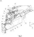
- FIG. 1 and Fig. 2 an assembly of a "brake-by-wire" brake system, designated overall by reference number 10, is shown in the installed state.
- the assembly 10 has a first brake control module 12, which is fluidly connected to a fluid container 14 for a brake fluid.
- the fluid container 14 is generically installed in the vertical direction Z above the first brake control module 12.
- the assembly 10 includes a second brake control module 16, which in the present case is arranged below the first brake control module 12 in the vehicle vertical direction Z.
- the two brake control modules 12, 16 are communicatively connected to one another.
- the first brake control module 12 also called the primary brake control module
- the second brake control module 16 which is also referred to as a secondary brake control module, forms a redundant fallback level that intervenes if the first brake control module 12 fails and builds up brake pressure.
- the first brake control module 12 has a first housing 18 and the second brake control module 16 has a second housing 20.
- the housings 18, 20 are formed with fluid connections 22 to which fluid lines 24 are connected.
- the housings 18, 20 are fluidly connected on the one hand to the fluid container 14 and on the other hand to brake circuits of the wheel brakes of the vehicle, not shown here.
- the brake control modules 12, 16 are arranged vertically below the fluid container 14.
- An electronic control unit (not shown here) is integrated in the housing 18 of the first brake control module 12, which, during normal operation of the brake system, controls a brake pressure control (also not shown) arranged in the brake control module 12, which in turn controls an electromechanical actuator 26 of the brake control module 12 in order to regulate the brake fluid in the brake circuits To put pressure on wheel brakes.
- the electronic control unit, the brake pressure control and/or the actuators 26 are arranged in particular in the first housing 18.
- the second brake control module 16 takes over the braking function.
- the second brake control module 16 also has an electronic control unit, not shown here, for controlling the brake pressure control device arranged in the brake control module 16, which in turn controls an actuator 28 in order to build up a brake pressure.
- the electronic control unit, the brake pressure control device and/or the actuator 28 of the second brake control module 16 are arranged in particular in the second housing 20.
- first brake control module 12 and the second brake control module 16 or their respective housings 18, 20 are connected to a vehicle body 32 via a holding device 30.
- the first brake control module 12 is, for example, screwed several times to the holding device 30, which in turn is connected to the vehicle body 32.
- the second brake control module 16 is supported on a longitudinal member 44 of the vehicle body 32 via its housing 20 with the interposition of the holding device 30.
- Fig. 1 is a failure of the holding device 30, for example due to a break at any point, expressed by several lightning-shaped representations.
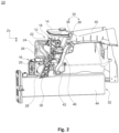
- Fig. 2 the stop device 34 of the assembly 10 according to the invention can be clearly seen.
- the stop device 34 is connected to the first brake control module 12.
- the stop device 34 is used to detect failure of the holding device 30 or to detect a loss of storage of the assembly 10.
- the stop device 34 is connected directly and indirectly to the first brake control module 12.
- the stop device 34 has stop elements 36, 38.
- the stop elements 36, 38 are at a defined distance from the vehicle body 32 in the vehicle longitudinal direction X, in the vehicle transverse direction Y and/or in the vehicle vertical direction Z.
- the stop device 34 is designed in such a way that at least one of the stop elements 36, 38 is in the vehicle longitudinal direction X, in the vehicle transverse direction Y and / or in the vehicle vertical direction Z due to the increased vibrations of the first brake control module 12 repeatedly hits the vehicle body 32, which serves, for example, as a resonance body.
- the mechanical interaction of the stop elements 36, 38 with the vehicle body 32 causes an acoustic abnormality, i.e. a mechanical, acoustic warning signal is emitted, which is transmitted into the passenger compartment in particular via airborne noise and/or structure-borne noise.
- the stop elements 36, 38 are preferably made of metal and/or hard plastic so that the acoustic impulse penetrates into the passenger compartment with as little dampening as possible.
- the stop element 36 of the stop device 34 is, for example, materially connected to the fluid container 14.
- the stop element 36 is, for example, made of plastic or injected into the fluid container 14 as a metal element.
- the distance between the suspension strut dome 40 and the stop element 36 is reduced, for example by accelerating the vehicle in the vehicle's longitudinal direction
- the first brake control module 12 is connected to the holding device 30 with the interposition of a connecting element 42.
- the stop element 38 is formed on the connecting element 42. It can be formed, for example, by a metal strip or the like.
- the stop element 38 is arranged at a distance from the vehicle body 32 over a predetermined distance in the vehicle longitudinal direction X and at a distance from a connecting strut 46 of the vehicle body 32 in the vehicle vertical direction Z. If the holding device 30 breaks or loosens, the stop element 38 repeatedly hits the vehicle body 32 and/or the connecting strut 46 due to the vibration excitation of the vehicle and causes a knocking noise.
Landscapes
- Engineering & Computer Science (AREA)
- Transportation (AREA)
- Mechanical Engineering (AREA)
- Physics & Mathematics (AREA)
- Electromagnetism (AREA)
- Fluid Mechanics (AREA)
- Valves And Accessory Devices For Braking Systems (AREA)
- Regulating Braking Force (AREA)
Abstract
Die Erfindung betrifft eine Baugruppe (10) für ein elektrohydraulisches Bremssystem eines Fahrzeugs, umfassend wenigstens ein Bremsregelmodul (12, 16), das eine elektronisch angesteuerte Druckbereitstellungseinrichtung aufweist, die im eingebauten Zustand der Baugruppe (10) mit wenigstens einer Radbremse des Fahrzeugs fluidleitend gekoppelt ist, und wobei das Bremsregelmodul (12, 16) mit einer Haltevorrichtung (30) zur Anordnung an eine Fahrzeugkarosserie (32) verbunden ist. Die Erfindung zeichnet sich dadurch aus, dass das Bremsregelmodul (12, 16) eine mechanische Anschlagvorrichtung (34) aufweist, die im eingebauten Zustand der Baugruppe (10) über einen Abstand beabstandet zu einem angrenzenden Fahrzeugbauteil angeordnet ist und durch Interaktion mit dem Fahrzeugbauteil bei einem Lagerungsverlust des Bremsregelmoduls (12, 16) ein Warnsignal ausgibt.The invention relates to an assembly (10) for an electro-hydraulic brake system of a vehicle, comprising at least one brake control module (12, 16), which has an electronically controlled pressure supply device which, when the assembly (10) is installed, is coupled in a fluid-conducting manner to at least one wheel brake of the vehicle , and wherein the brake control module (12, 16) is connected to a holding device (30) for arrangement on a vehicle body (32). The invention is characterized in that the brake control module (12, 16) has a mechanical stop device (34) which, when the assembly (10) is installed, is arranged at a distance from an adjacent vehicle component and by interacting with the vehicle component at a Loss of storage of the brake control module (12, 16) issues a warning signal.
Description
Die Erfindung betrifft eine Baugruppe eines Bremssystems für ein Fahrzeug gemäß der im Oberbegriff des Patentanspruches 1 angegebenen Art.The invention relates to an assembly of a braking system for a vehicle according to the type specified in the preamble of claim 1.
Neben klassischen Hydraulikbremssystemen, bei denen der Bremsdruck über ein fremdbetätigtes Bremspedal erzeugt wird, sind auch elektrohydraulische Fremdkraft-Bremssysteme und sogenannte Brake-By-Wire Bremssysteme bekannt.In addition to classic hydraulic brake systems, in which the brake pressure is generated via an externally operated brake pedal, electro-hydraulic external power brake systems and so-called brake-by-wire brake systems are also known.
Bei einer Hydraulikbremse wird die Bremskraft hydraulisch übertragen. D.h. ein Fahrer betätigt über das Bremspedal einen Kolben im Hauptbremszylinder, um Bremsflüssigkeit über Leitungen und Schläuche an die Radbremsen zu leiten und Bremsdruck in den Radbremsen aufzubauen. Dabei kann das Bremssystem ein elektronisch gesteuertes Fahrerassistenzsystem aufweisen, beispielsweise ein ESC-Bremsregelmodul, das über Sensoren einen kritischen Fahrzeugzustand erkennt und durch gezieltes Bremsen einzelner Räder dem Fahrer die Kontrolle über das Fahrzeug sichert. Das Bremsregelmodul, das auch als Bremsregelsystem bezeichnet wird, ist regelmäßig unmittelbar in Fahrtrichtung vor der Stirnwand positioniert. Es ist jedoch auch denkbar, dass es im Vorderwagenpackage freier positioniert ist, wobei es über Fluidleitungen mit dem Hauptbremszylinder verbunden ist.With a hydraulic brake, the braking force is transmitted hydraulically. This means that a driver uses the brake pedal to actuate a piston in the master brake cylinder in order to direct brake fluid to the wheel brakes via lines and hoses and to build up brake pressure in the wheel brakes. The braking system can have an electronically controlled driver assistance system, for example an ESC brake control module, which uses sensors to detect a critical vehicle condition and ensures the driver control of the vehicle by selectively braking individual wheels. The brake control module, which is also referred to as the brake control system, is regularly positioned directly in front of the front wall in the direction of travel. However, it is also conceivable that it is positioned more freely in the front car package, being connected to the master brake cylinder via fluid lines.
Bei einem elektrohydraulischen Fremdkraft-Bremssystem wirkt die ausgeübte Fußkraft lediglich als Steuersignal zum Ansteuern des Bremssystems. Der hydraulische Bremsdruck für die Radbremsen wird durch ein elektrisches Signal geregelt. Eine Auslenkung des Bremspedals aus seiner Ruhelage ist sensorisch detektiert, daraus wird ein Steuersignal ermittelt und eine Druckbereitstellungseinrichtung eines Bremsregelmoduls wird angesteuert, um den Bremsdruck in den Radbremsen aufzubauen. Das elektrohydraulische Bremssystem ist von elektrischer Energie abhängig und weist insbesondere eine hydraulische Rückfallebene auf. Bei einem Ausfall der Steuereinheit wird über Ventile der Druckbereitstellungeinrichtung eine direkte Verbindung zwischen dem Hauptbremszylinder und den Radbremsen einer Achse hergestellt, so dass eine Bremskraft durch die Muskelkraft des Fahrers aufgebaut wird. Das bedingt eine unmittelbare Anordnung des Bremsregelmoduls direkt an der Spritzwand des Fahrzeugs.With an electro-hydraulic external power braking system, the foot force exerted only acts as a control signal to activate the braking system. The hydraulic brake pressure for the wheel brakes is provided by an electrical one Signal regulated. A deflection of the brake pedal from its rest position is detected by sensors, a control signal is determined from this and a pressure supply device of a brake control module is activated in order to build up the brake pressure in the wheel brakes. The electrohydraulic braking system is dependent on electrical energy and in particular has a hydraulic fallback level. If the control unit fails, a direct connection is established between the master brake cylinder and the wheel brakes of an axle via valves of the pressure supply device, so that a braking force is built up by the driver's muscle strength. This requires the brake control module to be located directly on the bulkhead of the vehicle.
Sogenannte "Brake-By-Wire" Bremssysteme kommen immer häufiger zum Einsatz, beispielsweise bei hochautomatisiertem Fahren ab Level 3, welches ermöglicht, dass der Fahrzeugnutzer zeitweise nicht in der Fahrverantwortung ist und das Bremsen des Fahrzeugs autonom stattfinden kann. Aufgrund von Daten und einer Vielzahl von Fahrzeugsensoriken steuert eine Steuereinheit eine Druckbereitstellungseinrichtung an, die in den Bremskreisen einen Bremsdruck aufbaut. Aufgrund der Abhängigkeit dieses Bremssystems von der Funktionssicherheit der Fahrzeugelektronik ist eine Rückfallebene vorhanden, die bei Ausfall der Normalebene eingreift und einen Bremsdruck aufbaut. In der
Durch die mechanische Entkoppelung des "Brake-By-Wire" Bremssystems müssen die Bremsregelmodule der jeweiligen Normal- und Rückfallebene nicht mehr zwingend an einer bestimmten Position vor dem Fahrer direkt an der Spritzwand des Fahrzeugs montiert sein, sondern können im Vorderwagenpackage freier und einfacher positioniert sein.Due to the mechanical decoupling of the "Brake-By-Wire" braking system, the brake control modules of the respective normal and fallback levels no longer necessarily have to be mounted in a specific position in front of the driver directly on the vehicle's bulkhead, but can be positioned more freely and easily in the front of the vehicle .
Üblicherweise wird ein Bremsregelmodul eines Bremssystems mit einer Haltevorrichtung vormontiert und anschließend als Baugruppe in das Fahrzeug eingebaut. Dabei ist das Bremsregelmodul unter Zwischenschaltung der Haltevorrichtung mit der Fahrzeugkarosserie verbunden. Bricht diese Haltevorrichtung an einer beliebigen Stelle, z.B. an einem Haltearm, vergrößert sich der Bewegungsfreiraum des Bremsregelmoduls. Das Gewicht des Bremsregelmoduls führt zu einer erhöhten Belastung von Fluidanschlüssen sowie Fluidleitungen. Durch die vom Fahrwerk übertragenen Anregungen kann es zu weiteren Beschädigungen kommen, beispielsweise zu einem Bruch der Fluidleitungen oder -anschlüssen. Die Folge ist ein Verlust von Bremsfluid und Druckverlust an den Radbremsen. Technisch ist der Bruch der Haltevorrichtung schwer zu detektieren, deswegen kann ein Fahrzeug lange unbemerkt mit der gebrochenen Haltevorrichtung fahren, ohne dass es seitens eines Fahrzeugsystems detektiert oder angezeigt wird. In der Folge kann es jedoch möglicherweise zu einem Totalausfall des Bremssystems kommen.A brake control module of a brake system is usually pre-assembled with a holding device and then installed as an assembly in the vehicle built-in. The brake control module is connected to the vehicle body with the interposition of the holding device. If this holding device breaks at any point, for example on a holding arm, the freedom of movement of the brake control module increases. The weight of the brake control module leads to increased stress on fluid connections and fluid lines. The excitations transmitted by the chassis can cause further damage, for example a break in the fluid lines or connections. The result is a loss of brake fluid and pressure loss in the wheel brakes. Technically, the breakage of the holding device is difficult to detect, which is why a vehicle can drive unnoticed for a long time with the broken holding device without it being detected or displayed by a vehicle system. However, this could potentially lead to a complete failure of the braking system.
Aus dem Stand der Technik sind Bremssysteme bekannt, denen eine Anschlagvorrichtung zugeordnet ist, die ein akustisches Warnsignal auslöst. So ist in der
Die
Der Erfindung liegt die Aufgabe zugrunde, eine Baugruppe eines Bremssystems eines Fahrzeugs gemäß der im Oberbegriff des Patentanspruches 1 angegebenen Art derart weiterzubilden, dass ein Lagerungsverlust der Baugruppe mittels einfachen, kostengünstigen und zuverlässigen Mitteln rasch erkennbar ist, um Schäden an der Baugruppe weitgehend zu verhindern.The invention is based on the object of developing an assembly of a braking system of a vehicle according to the type specified in the preamble of claim 1 in such a way that a storage loss of the assembly can be quickly identified using simple, inexpensive and reliable means in order to largely prevent damage to the assembly.
Diese Aufgabe wird durch die kennzeichnenden Merkmale des Patentanspruches 1 in Verbindung mit seinen Oberbegriffsmerkmalen gelöst.This task is solved by the characterizing features of patent claim 1 in conjunction with its generic features.
Die Unteransprüche bilden vorteilhafte Weiterbildungen der Erfindung.The subclaims form advantageous developments of the invention.
In bekannter Art und Weise umfasst eine Baugruppe eines insbesondere elektrohydraulischen Bremssystems für ein Fahrzeug wenigstens ein Bremsregelmodul, das eine elektronisch angesteuerte Druckbereitstellungseinrichtung aufweist. Die Druckbereitstellungseinrichtung kann insbesondere einen Hydraulikblock mit einer Bremsdrucksteuerung, einem Elektromotor und einer Pumpe aufweisen. Das Bremsregelmodul kann auch als Bremsregelsystem bezeichnet werden.In a known manner, an assembly of a particularly electro-hydraulic brake system for a vehicle comprises at least one brake control module which has an electronically controlled pressure supply device. The pressure supply device can in particular have a hydraulic block with a brake pressure control, an electric motor and a pump. The brake control module can also be referred to as a brake control system.
Im eingebauten Zustand der Baugruppe ist die Druckbereitstellungseinrichtung mit wenigstens einer Radbremse des Fahrzeugs fluidleitend verbunden. Die Druckbereitstellungseinrichtung ist über Fluidanschlüsse und Fluidleitungen für ein Bremsfluid mit der Radbremse gekoppelt. Die Druckbereitstellungseinrichtung wird in Abhängigkeit von Daten und einer Vielzahl von unterschiedlichen Fahrzeugsensoriken durch die elektronische Steuereinheit angesteuert, um einen Bremsdruck in der Radbremse aufzubauen.When the assembly is installed, the pressure supply device is fluidly connected to at least one wheel brake of the vehicle. The pressure supply device is coupled to the wheel brake via fluid connections and fluid lines for a brake fluid. The pressure provision device is controlled by the electronic control unit depending on data and a large number of different vehicle sensors in order to build up brake pressure in the wheel brake.
Das Bremsregelmodul ist im eingebauten Zustand der Baugruppe über eine Haltevorrichtung mit der Fahrzeugkarosserie verbunden. Das Bremsregelmodul kann beispielsweise ein Gehäuse aufweisen, das mehrfach mit der Haltevorrichtung verschraubt ist, wobei die Haltevorrichtung mit der Fahrzeugkarosserie verbunden ist, beispielsweise einem Längsträger oder einer Spritzwand, die den Motorraum von der Fahrgastzelle trennt. Die Haltevorrichtung kann beispielsweise als eine Leiste, ein U-Profil, ein Freiformteil oder dergleichen ausgebildet sein. Es ist denkbar, dass sie aus Metall oder aus Kunststoff gebildet ist.When the assembly is installed, the brake control module is connected to the vehicle body via a holding device. The brake control module can, for example, have a housing that is screwed several times to the holding device, the holding device being connected to the vehicle body, for example a longitudinal member or a bulkhead that separates the engine compartment from the passenger compartment. The holding device can be designed, for example, as a strip, a U-profile, a free-form part or the like. It is conceivable that it is made of metal or plastic.
Erfindungsgemäß ist das Bremsregelmodul mit einer mechanischen Anschlagvorrichtung verbunden, die im eingebauten Zustand der Baugruppe über einen Abstand beabstandet zu einem angrenzenden Fahrzeugbauteil angeordnet ist und durch Interaktion mit dem Fahrzeugbauteil bei einem Lagerungsverlust des Bremsregelmoduls ein Warnsignal ausgibt.According to the invention, the brake control module is connected to a mechanical stop device which, when the assembly is installed, is arranged at a distance from an adjacent vehicle component and, by interacting with the vehicle component, emits a warning signal in the event of a loss of storage of the brake control module.
Die Anschlagvorrichtung weist bei intaktem Zustand der Haltevorrichtung einen definierten Abstand zum angrenzenden Fahrzeugbauteil auf. Der Abstand ist in Fahrzeuglängsrichtung, in Fahrzeugquerrichtung und/oder in Fahrzeughochrichtung vorbestimmt. Der definierte Abstand ist derart konzipiert, dass im Versagensfall der Haltevorrichtung, beispielsweise durch eine Lockerung und/oder einen Bruch an einer beliebigen Stelle, die Anschlagvorrichtung aufgrund schwingungsmechanischen Anregungen des Fahrwerks während des Fahrbetriebs, z.B. durch Beschleunigungen oder Verzögerungen, durch Querdynamiken wie Kurvenfahrten und/oder bei Fahrt über Schwellen, Schlaglöcher oder dergleichen, durch die verstärkte Schwingungen mit dem insbesondere unmittelbar angrenzenden Fahrzeugbauteil interagiert, indem sie wiederholt darauf auftrifft oder schlägt. Dabei ist der Abstand in Abhängigkeit einer unmittelbaren Umgebung der Baugruppe und unter Berücksichtigung von Schwingungseinwirkungen und Toleranzen konzipiert. Dadurch trifft die Anschlagvorrichtung bei Lagerungsverlust schon früh auf das angrenzende Fahrzeugbauteil. Auf diese Weise kann die Bewegungsbahn des Bremsregelmoduls begrenzt werden.When the holding device is in an intact state, the stop device has a defined distance from the adjacent vehicle component. The distance is predetermined in the longitudinal direction of the vehicle, in the transverse direction of the vehicle and/or in the vertical direction of the vehicle. The defined distance is designed in such a way that in the event of failure of the holding device, for example due to a loosening and/or a break at any point, the stop device is due to vibration-mechanical excitations of the chassis during driving, e.g. due to accelerations or decelerations, due to transverse dynamics such as cornering and/or or when driving over thresholds, potholes or the like, through which increased vibrations interact with the particularly immediately adjacent vehicle component by repeatedly hitting or hitting it. The distance is designed depending on the immediate surroundings of the assembly and taking into account vibration effects and tolerances. As a result, the stop device hits the adjacent vehicle component at an early stage in the event of a loss of storage. In this way, the movement path of the brake control module can be limited.
Aufgrund von schwingungstechnischen Anregungen wiederholt sich die mechanische Interaktion der Anschlagvorrichtung mit dem angrenzenden Fahrzeugbauteil, das als Resonanzkörper dient und durch das Auftreffen der Anschlagvorrichtung ein sich wiederholendes akustisches Signal ausgibt, das insbesondere über Luftschall und/oder Körperschall in die Fahrgastzelle übertragen wird. Die Anschlagvorrichtung dient also als Anschlagakustik bzw. Schallquelle, die während des Fahrbetriebs einen Hinweis oder ein Warnsignal über den Verlust der Lagerung der Baugruppe auslöst. Die Anschlagvorrichtung stellt eine Kontrolleinrichtung dar, die einen Fahrzeugnutzer mit sehr einfachen und günstigen Mitteln darüber informiert, dass die Haltevorrichtung locker, defekt und/oder gebrochen ist.Due to vibration-related stimuli, the mechanical interaction of the stop device with the adjacent vehicle component is repeated, which serves as a resonance body and, when the stop device hits, emits a repeating acoustic signal, which is transmitted into the passenger compartment in particular via airborne sound and/or structure-borne noise. The stop device therefore serves as stop acoustics or sound source that triggers an indication or a warning signal about the loss of bearings of the assembly while driving. The stop device represents a control device that informs a vehicle user using very simple and inexpensive means that the holding device is loose, defective and / or broken.
In vorteilhafter Weise übt die Anschlagvorrichtung ein mechanisch angeregtes, akustisches Warnsignal ohne elektronische Anzeigen, optische Signale oder dergleichen aus, welches vor einer dauerhaften Überlastung des Bremsregelmoduls, der Fluidleitungen und Fluidanschlüsse warnt, wodurch Beschädigungen am Bremssystem reduziert oder größtenteils vermieden sind.Advantageously, the stop device emits a mechanically stimulated, acoustic warning signal without electronic displays, optical signals or the like, which warns of a permanent overload of the brake control module, the fluid lines and fluid connections, whereby damage to the brake system is reduced or largely avoided.
Bevorzugt ist die Anschlagvorrichtung kraftschlüssig, formschlüssig und/oder stoffschlüssig mit dem Bremsregelmodul verbunden. Die Anschlagvorrichtung kann unter anderem am Bremsregelmodul angeschraubt, angeklemmt, angeschweißt, eingespritzt und /oder angeklebt sein.The stop device is preferably connected to the brake control module in a non-positive, form-fitting and/or material-locking manner. The stop device can, among other things, be screwed, clamped, welded, injected and/or glued to the brake control module.
Gemäß einer Ausführungsform weist die Anschlagvorrichtung wenigstens ein Anschlagelement auf. Das Anschlagelement dient als eine Anschlagfläche, d.h. als ein körperliches Hindernis oder eine Stelle, die bei Verlust der Lagerung an ein insbesondere unmittelbar angrenzendes Fahrzeugbauteil schlägt oder trifft. Das Anschlagelement kann beispielsweise als eine Leiste ausgebildet sein, die auf einfache Weise am Bremsregelmodul in einem vordefinierten Abstand zum Fahrzeugbauteil angeordnet werden kann.According to one embodiment, the stop device has at least one stop element. The stop element serves as a stop surface, i.e. as a physical obstacle or a point that hits or hits a particularly immediately adjacent vehicle component if the bearing is lost. The stop element can be designed, for example, as a bar that can be easily arranged on the brake control module at a predefined distance from the vehicle component.
Vorzugsweise ist das Anschlagelement aus einem harten und/oder festen Werkstoff ausgebildet. Das Anschlagelement ist robust und weist eine geringe Dämpfung sowie eine hohe Übertragung des akustischen Impulses auf. Das Anschlagelement kann bspw. aus Kunststoff und/oder Metall ausgebildet sein. Es kann z.B. als eine Metallleiste ausgebildet sein.The stop element is preferably made of a hard and/or solid material. The stop element is robust and has low attenuation and high transmission of the acoustic impulse. The stop element can be made of plastic and/or metal, for example. It can be designed, for example, as a metal strip.
Vorzugsweise ist die Anschlagvorrichtung mit einem Verbindungselement verbunden, über welches das Bremsregelmodul mit der Haltevorrichtung verbunden ist. Das Bremsregelmodul ist unter Zwischenschaltung eines Verbindungselements mit der Haltevorrichtung verbunden. D.h. die Anschlagvorrichtung kann mittelbar mit dem Bremsregelmodul verbunden sein. Das Verbindungselement kann beispielsweise als Adapter zur Verbindung des Bremsregelmoduls mit der Haltevorrichtung dienen. Am Verbindungselement ist beispielsweise ein Anschlagelement ausgebildet, das über einen vorbestimmten Abstand beabstandet zum angrenzenden Fahrzeugbauteil, beispielsweise die Fahrzeugkarosserie, angeordnet ist. Wenn die Haltevorrichtung bricht oder sich lockert, trifft das Anschlagelement durch die Schwingungsanregung des Fahrzeugs wiederholt auf das angrenzende Fahrzeugbauteil und verursacht ein klopfendes Geräusch.The stop device is preferably connected to a connecting element via which the brake control module is connected to the holding device. The brake control module is connected to the holding device with the interposition of a connecting element. This means that the stop device can be indirectly connected to the brake control module. The connecting element can, for example, serve as an adapter for connecting the brake control module to the holding device. For example, a stop element is formed on the connecting element, which is arranged at a predetermined distance from the adjacent vehicle component, for example the vehicle body. If the holding device breaks or becomes loose, the stop element repeatedly hits the adjacent vehicle component due to the vibration excitation of the vehicle and causes a knocking noise.
Gemäß einer Ausführungsform ist das Bremsregelmodul dazu ausgebildet radindividuelle Bremsdrücke aufzubauen. Das Bremsregelmodul kann z.B. als ein ESC-Aggregat, welches auch als ESP-Aggregat bezeichnet werden kann, eines konventionellen elektrohydraulischen Bremssystems ausgebildet sein, das ein elektronisch gesteuertes Fahrerassistenzsystem aufweist. Das Bremsregelmodul ist über die Druckbereitstellungseinrichtung mechanisch bzw. fluidisch mit einer Bremsbetätigungseinheit des Fahrzeugs verbunden, d.h. mit einem Bremskraftverstärker, der über ein Bremspedal von einem Fahrzeugnutzer betätigbar ist. Das ESC-Aggregat greift lediglich in einen Bremsvorgang ein, wenn es sensorisch einen kritischen Fahrzeugzustand erkennt. Dann wird die Druckbereitstellungseinrichtung über elektronische Signale angesteuert, um beispielsweise nur einen Bremssattel einer Radbremse hydraulisch ohne einen Druckeingang des Hauptzylinders zu betreiben, um dadurch das Fahrzeug zu stabilisieren.According to one embodiment, the brake control module is designed to build up wheel-specific brake pressures. The brake control module can be designed, for example, as an ESC unit, which can also be referred to as an ESP unit, of a conventional electro-hydraulic brake system that has an electronically controlled driver assistance system. The brake control module is mechanically or fluidly connected to a brake actuation unit of the vehicle via the pressure supply device, i.e. to a brake booster that can be actuated by a vehicle user via a brake pedal. The ESC unit only intervenes in a braking process if it detects a critical vehicle condition using sensors. Then the pressure supply device is controlled via electronic signals in order, for example, to operate only one brake caliper of a wheel brake hydraulically without a pressure input from the master cylinder in order to thereby stabilize the vehicle.
Alternativ ist es denkbar, dass das Bremsregelmodul durch eine Integration des ESC-Aggregats in den Bremskraftverstärker ausgebildet ist. Die Kombination wird als integriertes Bremsregelsystem bzw. Bremsregelmodul bezeichnet.Alternatively, it is conceivable that the brake control module is designed by integrating the ESC unit into the brake booster. The combination is referred to as an integrated brake control system or brake control module.
Gemäß einer alternativen Ausführungsform ist das Bremsregelmodul als das im Normalbetrieb eines "Brake-by-Wire" Bremssystems aktive, erste Bremsregelmodul ausgebildet, das auch als primäres Bremsregelmodul bezeichnet werden kann. D.h. das erste Bremsregelmodul löst in Abhängigkeit von Daten unterschiedlicher Fahrzeugsensoriken einen Bremsvorgang des Fahrzeugs aus, indem die Druckbereitstellungseinrichtung angesteuert wird, um einen Bremsdruck in den Radbremsen zu erzeugen. Bei der Bauart "Brake-By-Wire" ist durch die mechanische Entkopplung einer Betätigungseinrichtung und einer Stelleinrichtung des Bremssystems eine unabhängige Anordnung des Bremsregelmoduls an einer beliebigen Position im Fahrzeugpackage möglich, so dass ein Fahrzeugbauraum optimal genutzt werden kann.According to an alternative embodiment, the brake control module is designed as the first brake control module that is active during normal operation of a "brake-by-wire" brake system, which can also be referred to as the primary brake control module. I.e. the first brake control module triggers a braking process of the vehicle depending on data from different vehicle sensors by controlling the pressure supply device in order to generate a brake pressure in the wheel brakes. With the "Brake-By-Wire" design, the mechanical decoupling of an actuating device and an adjusting device of the brake system enables the brake control module to be arranged independently at any position in the vehicle package, so that vehicle installation space can be optimally used.
Bevorzugt ist die Anschlagvorrichtung mit einem Fluidbehälter des ersten Bremsregelmoduls verbunden. Bei einem "Brake-By Wire" Bremssystem ist das im Normalbetrieb aktive erste Bremsregelmodul fluidisch mit einem Fluidbehälter für Bremsfluid verbunden, das zum Erzeugen des Bremsdrucks in den Radbremsen verwendet wird. Am Fluidbehälter kann ein Anschlagelement ausgebildet bzw. befestigt oder eingespritzt sein. Bei defekter Haltevorrichtung oder Lagerungsverlust der Baugruppe kann das Anschlagelement beispielsweise aufgrund einer Fahrzeugbeschleunigung wiederholt Kontakt zu einem angrenzenden Fahrzeugbauteil herstellen, wodurch ein Klopfgeräusch bzw. Warnsignal verursacht ist.The stop device is preferably connected to a fluid container of the first brake control module. In a "brake-by-wire" brake system, the first brake control module, which is active during normal operation, is fluidly connected to a fluid container for brake fluid, which is used to generate the brake pressure in the wheel brakes. A stop element can be formed or attached or injected on the fluid container. If the holding device is defective or the assembly is lost, the stop element can repeatedly make contact with an adjacent vehicle component, for example due to vehicle acceleration, causing a knocking noise or warning signal.
Gemäß einer bevorzugten Ausführungsform stellt das Fahrzeugbauteil ein redundantes, zweites Bremsregelmodul des "Brake-By Wire" Bremssystems dar, das auch als sekundäres Bremsregelmodul bezeichnet wird. Bei dieser Art Bremssystem ist eine Rückfallebene vorhanden. D.h. die Baugruppe umfasst ein redundantes, zweites Bremsregelmodul, welches kommunizierend mit dem ersten Bremsregelmodul verbunden ist und das autonome Bremsen im Falle einer Störung des ersten Bremsregelmoduls übernimmt. Das redundante zweite Bremsregelmodul ist insbesondere unmittelbar vertikal unterhalb des ersten Bremsregelmoduls verbaut. Die jeweiligen Bremsregelmodule sind fluidtechnisch über Fluidanschlüsse und Fluidleitungen einerseits mit dem Fluidbehälter und andererseits mit den Radbremsen verbunden. Ein Bruch oder eine Lockerung der Haltevorrichtung führt dazu, dass die Anschlagvorrichtung wiederholt auf das redundante zweite Bremsregelmodul schlägt und ein akustisches Warnsignal verursacht. Insbesondere kann die Anschlagvorrichtung wiederholt auf ein Gehäuse, z.B. ein Metallgehäuse des redundanten zweiten Bremsregelmoduls treffen.According to a preferred embodiment, the vehicle component represents a redundant, second brake control module of the "brake-by-wire" brake system, which is also referred to as a secondary brake control module. This type of braking system has a fallback level. Ie the assembly includes a redundant, second brake control module, which is communicatively connected to the first brake control module and takes over autonomous braking in the event of a fault in the first brake control module. The redundant second brake control module is installed in particular directly vertically below the first brake control module. The respective brake control modules are fluidly connected via fluid connections and fluid lines on the one hand to the fluid container and on the other hand to the wheel brakes. A Breakage or loosening of the holding device causes the stop device to repeatedly hit the redundant second brake control module and cause an acoustic warning signal. In particular, the stop device can repeatedly hit a housing, for example a metal housing, of the redundant second brake control module.
Vorzugsweise ist das Fahrzeugbauteil als ein Element der Fahrzeugkarosserie ausgebildet. Es ist denkbar, dass die Anschlagvorrichtung über einen definierten Abstand beispielsweise zu einem Federbeindom, einem Längsträger, der Stirnwand des Motorraums, einer Verbindungsstrebe oder einem anderen Teil der Fahrzeugkarosserie angeordnet ist. Bei einem Lagerungsverlust der Baugruppe oder bei einem Bruch der Haltevorrichtung weist das Bremsregelmodul eine erhöhte Bewegungsfreiheit auf. Durch die Auslenkung des Bremsregelmoduls trifft oder schlägt die Anschlagvorrichtung wiederholt auf die Fahrzeugkarosserie. Diese ist robust ausgelegt und hauptsächlich aus Metall gebildet, so dass als ein Resonanzkörper wirkt. Dadurch wird das akustische Warnsignal erfolgreich in die Fahrgastzelle weitergeleitet.The vehicle component is preferably designed as an element of the vehicle body. It is conceivable that the stop device is arranged at a defined distance, for example from a suspension strut tower, a side member, the front wall of the engine compartment, a connecting strut or another part of the vehicle body. If the assembly loses storage or the holding device breaks, the brake control module has increased freedom of movement. Due to the deflection of the brake control module, the stop device repeatedly hits or hits the vehicle body. This is robust and made mainly of metal so that it acts as a resonance body. This means that the acoustic warning signal is successfully transmitted to the passenger compartment.
Weitere Vorteile und Anwendungsmöglichkeiten der vorliegenden Erfindung ergeben sich aus der nachfolgenden Beschreibung in Verbindung mit dem in der Zeichnung dargestellten Ausführungsbeispiel.Further advantages and possible applications of the present invention result from the following description in conjunction with the exemplary embodiment shown in the drawing.
In der Zeichnung bedeutet:
- Fig. 1
- eine perspektivische Darstellung einer Baugruppe eines aus dem Stand der Technik bekannten Bremssystems schräg von vorne; und
- Fig. 2
- eine seitliche Ansicht einer erfindungsgemäßen Baugruppe eines Bremssystems.
- Fig. 1
- a perspective view of an assembly of a braking system known from the prior art, diagonally from the front; and
- Fig. 2
- a side view of a brake system assembly according to the invention.
In
Die Baugruppe 10 weist ein erstes Bremsregelmodul 12 auf, das fluidleitend mit einem Fluidbehälter 14 für ein Bremsfluid verbunden ist. Der Fluidbehälter 14 ist gattungsgemäß in Vertikalrichtung Z über dem ersten Bremsregelmodul 12 verbaut.The
Die Baugruppe 10 umfasst ein zweites Bremsregelmodul 16, das vorliegend in Fahrzeughochrichtung Z unter dem ersten Bremsregelmodul 12 angeordnet ist. Die beiden Bremsregelmodule 12, 16 sind kommunizierend miteinander verbunden. Im Normalbetrieb des "Brake-by-Wire" Bremssystems dient das erste Bremsregelmodul 12, auch primäres Bremsregelmodul genannt, zum aktiven Aufbau eines Bremsdrucks im Bremssystem. Das zweite Bremsregelmodul 16, das auch als sekundäres Bremsregelmodul bezeichnet wird, bildet eine redundante Rückfallebene, die bei Ausfall des ersten Bremsregelmoduls 12 eingreift und einen Bremsdruck aufbaut.The
Das erste Bremsregelmodul 12 weist vorliegend ein erstes Gehäuse 18 und das zweite Bremsregelmodul 16 ein zweites Gehäuse 20 auf. Die Gehäuse 18, 20 sind mit Fluidanschlüssen 22 ausgebildet, an denen Fluidleitungen 24 angeschlossen sind. Die Gehäuse 18, 20 sind fluidtechnisch einerseits mit dem Fluidbehälter 14 und andererseits mit vorliegend nicht dargestellten Bremskreisen der Radbremsen des Fahrzeugs verbunden. Zur Entlüftung des Bremssystems und zur Reduzierung von Ansaugwiderständen sind die Bremsregelmodule 12, 16 vertikal unter dem Fluidbehälter 14 angeordnet.In the present case, the first
Im Gehäuse 18 des ersten Bremsregelmoduls 12 ist eine vorliegend nicht dargestellte elektronische Steuereinheit integriert, die im Normalbetrieb des Bremssystems eine im Bremsregelmodul 12 angeordnete ebenfalls nicht dargestellte Bremsdrucksteuerung ansteuert, welche wiederum einen elektromechanischen Aktuator 26 des Bremsregelmoduls 12 ansteuert, um das Bremsfluid in den Bremskreisen der Radbremsen unter Druck zu setzen. Die elektronische Steuereinheit, die Bremsdrucksteuerung und/oder der Aktuatoren 26 sind insbesondere im ersten Gehäuse 18 angeordnet.An electronic control unit (not shown here) is integrated in the
Im Falle eines Ausfalls des ersten Bremsregelmoduls 12 übernimmt das zweite Bremsregelmodul 16 die Bremsfunktion. Das zweite Bremsregelmodul 16 weist ebenfalls eine vorliegend nicht dargestellte elektronische Steuereinheit zur Ansteuerung der im Bremsregelmodul 16 angeordneten Bremsdrucksteuereinrichtung, welche wiederum einen Aktuator 28 ansteuert, um einen Bremsdruck aufzubauen. Die elektronische Steuereinheit, die Bremsdrucksteuereinrichtung und/oder der Aktuator 28 des zweiten Bremsregelmoduls 16 sind insbesondere im zweiten Gehäuse 20 angeordnet.In the event of a failure of the first
In
In
In
Die Anschlagvorrichtung 34 ist vorliegend mittelbar sowie unmittelbar mit dem ersten Bremsregelmodul 12 verbunden. Die Anschlagvorrichtung 34 weist Anschlagelemente 36, 38 auf. Im intakten Zustand der Haltevorrichtung 30 weisen die Anschlagelemente 36, 38 in Fahrzeuglängsrichtung X, in Fahrzeugquerrichtung Y und/oder in Fahrzeughochrichtung Z einen definierten Abstand zur Fahrzeugkarosserie 32 auf.In the present case, the
Im defekten Zustand der Haltevorrichtung 30 bzw. bei Lagerungsverlust der Baugruppe 10 ist die Anschlagvorrichtung 34 vorliegend derart konzipiert, dass wenigstens eines der Anschlagelemente 36, 38 aufgrund der verstärkten Schwingungen des ersten Bremsregelmoduls 12 in Fahrzeuglängsrichtung X, in Fahrzeugquerrichtung Y und/oder in Fahrzeughochrichtung Z wiederholt auf die Fahrzeugkarosserie 32 trifft, die beispielweise als Resonanzkörper dient. Durch die mechanische Interaktion der Anschlagelemente 36, 38 mit der Fahrzeugkarosserie 32 wird eine akustischen Auffälligkeit bewirkt, d.h. ein mechanisches, akustisches Warnsignal wird ausgegeben, das insbesondere über Luftschall und/oder Körperschall in die Fahrgastzelle übertragen wird. Die Anschlagelemente 36, 38 sind bevorzugt aus Metall und/oder hartem Kunststoff gebildet, damit der akustische Impuls möglichst ungedämpft in die Fahrgastzelle eindringt.If the holding
Vorliegend ist das Anschlagelement 36 der Anschlagvorrichtung 34 beispielsweise stoffschlüssig mit dem Fluidbehälter 14 verbunden. Das Anschlagelement 36 ist z.B. aus Kunststoff gebildet oder als Metallelement in den Fluidbehälter 14 eingespritzt. In Fahrzeuglängsrichtung X ist es vorliegend über einen definierten Abstand beabstandet zu einem Federbeindom 40 der Fahrzeugkarosserie 32 angeordnet. Im Versagensfall der Haltevorrichtung wird z.B. durch eine Beschleunigung des Fahrzeugs in Fahrzeuglängsrichtung X der Abstand zwischen dem Federbeindom 40 und dem Anschlagelement 36 verringert und das Anschlagelement 36 trifft oder schlägt wiederholend auf den Federbeindom 40.In the present case, the
Das erste Bremsregelmodul 12 ist vorliegend unter Zwischenschaltung eines Verbindungselements 42 mit der Haltevorrichtung 30 verbunden. Am Verbindungselement 42 ist vorliegend das Anschlagelement 38 ausgebildet. Es kann beispielsweise durch eine Metallleiste oder dergleichen gebildet sein. Das Anschlagelement 38 ist vorliegend über jeweils einen vorbestimmten Abstand in Fahrzeuglängsrichtung X beabstandet zur Fahrzeugkarosserie 32 und in Fahrzeughochrichtung Z beabstandet zu einer Verbindungsstrebe 46 der Fahrzeugkarosserie 32 angeordnet. Wenn die Haltevorrichtung 30 bricht oder sich lockert, trifft das Anschlagelement 38 durch die Schwingungsanregung des Fahrzeugs wiederholt auf die Fahrzeugkarosserie 32 und/oder die Verbindungsstrebe 46 und verursacht ein klopfendes Geräusch.In the present case, the first
Claims (10)
dadurch gekennzeichnet, dass
das Bremsregelmodul (12, 16) eine mechanische Anschlagvorrichtung (34) aufweist, die im eingebauten Zustand der Baugruppe (10) über einen Abstand beabstandet zu einem angrenzenden Fahrzeugbauteil angeordnet ist und durch Interaktion mit dem Fahrzeugbauteil bei einem Lagerungsverlust des Bremsregelmoduls (12, 16) ein Warnsignal ausgibt.Assembly (10) for a brake system of a vehicle, comprising at least one brake control module (12, 16), which has an electronically controlled pressure supply device which, when the assembly (10) is installed, is fluidly coupled to at least one wheel brake of the vehicle, and wherein the brake control module (12, 16) is connected to a holding device (30) for arrangement on a vehicle body (32),
characterized in that
the brake control module (12, 16) has a mechanical stop device (34) which, when the assembly (10) is installed, is arranged at a distance from an adjacent vehicle component and by interacting with the vehicle component in the event of a storage loss of the brake control module (12, 16) issues a warning signal.
dadurch gekennzeichnet, dass
die Anschlagvorrichtung (34) kraftschlüssig, formschlüssig und/oder stoffschlüssig mit dem Bremsregelmodul (12, 16) verbunden ist.Assembly according to claim 1,
characterized in that
the stop device (34) is connected to the brake control module (12, 16) in a force-fitting, form-fitting and/or material-locking manner.
dadurch gekennzeichnet, dass
die Anschlagvorrichtung (34) wenigstens ein Anschlagelement (36, 38) aufweist.Assembly according to one of claims 1 or 2,
characterized in that
the stop device (34) has at least one stop element (36, 38).
dadurch gekennzeichnet, dass
das Anschlagelement (36, 38) aus einem harten und/oder festen Werkstoff gebildet ist.Assembly according to claim 3,
characterized in that
the stop element (36, 38) is made of a hard and/or solid material.
dadurch gekennzeichnet, dass
die Anschlagvorrichtung (34) an einem Verbindungselement (40) angeordnet ist, über welches das Bremsregelmodul (12, 16) mit der Haltevorrichtung (30) verbunden ist.Assembly according to one of claims 1 to 4,
characterized in that
the stop device (34) is arranged on a connecting element (40), via which the brake control module (12, 16) is connected to the holding device (30).
dadurch gekennzeichnet, dass
das Bremsregelmodul (12, 16) dazu ausgebildet ist radindividuelle Bremsdrücke aufzubauen.Assembly according to one of claims 1 to 5,
characterized in that
the brake control module (12, 16) is designed to build up wheel-specific brake pressures.
dadurch gekennzeichnet, dass
das Bremsregelmodul (12,16) als das im Normalbetrieb eines "Brake-by-Wire" Bremssystems aktive, erste Bremsregelmodul (12) ausgebildet ist.Assembly according to one of claims 1 to 5,
characterized in that
the brake control module (12, 16) is designed as the first brake control module (12) which is active in normal operation of a “brake-by-wire” brake system.
dadurch gekennzeichnet, dass
die Anschlagvorrichtung (34) mit einem Fluidbehälter (14) des ersten Bremsregelmoduls (12) verbunden ist.Assembly according to claim 7,
characterized in that
the stop device (34) is connected to a fluid container (14) of the first brake control module (12).
dadurch gekennzeichnet, dass
das Fahrzeugbauteil als ein redundantes, zweites Bremsregelmodul (16) ausgebildet ist.Assembly according to claim 7 or 8,
characterized in that
the vehicle component is designed as a redundant, second brake control module (16).
dadurch gekennzeichnet, dass
das Fahrzeugbauteil als ein Element der Fahrzeugkarosserie (32) ausgebildet ist.Assembly according to one of claims 1 to 9,
characterized in that
the vehicle component is designed as an element of the vehicle body (32).
Applications Claiming Priority (1)
| Application Number | Priority Date | Filing Date | Title |
|---|---|---|---|
| DE102022121745.0A DE102022121745A1 (en) | 2022-08-29 | 2022-08-29 | Brake system assembly |
Publications (1)
| Publication Number | Publication Date |
|---|---|
| EP4331932A1 true EP4331932A1 (en) | 2024-03-06 |
Family
ID=87517459
Family Applications (1)
| Application Number | Title | Priority Date | Filing Date |
|---|---|---|---|
| EP23187611.1A Pending EP4331932A1 (en) | 2022-08-29 | 2023-07-25 | Assembly of a brake system |
Country Status (4)
| Country | Link |
|---|---|
| US (1) | US20240067149A1 (en) |
| EP (1) | EP4331932A1 (en) |
| CN (1) | CN117622087A (en) |
| DE (1) | DE102022121745A1 (en) |
Citations (5)
| Publication number | Priority date | Publication date | Assignee | Title |
|---|---|---|---|---|
| FR371537A (en) | 1906-11-16 | 1907-03-09 | Jacques Pierre De Braam | Connection device between a valve connected to the continuous brake line of railway trains, or to any other warning or indicating device, and a shaft controlled by levers when passing knockers placed on the track |
| CN2823073Y (en) | 2005-06-23 | 2006-10-04 | 周兆海 | Braking regulating prompting device |
| US20180265062A1 (en) * | 2017-03-14 | 2018-09-20 | Honda Motor Co., Ltd. | Side-by-side all-terrain vehicle |
| DE102017211955A1 (en) | 2017-07-12 | 2019-01-17 | Continental Teves Ag & Co. Ohg | Brake system with an additional module |
| US20200114894A1 (en) * | 2017-06-29 | 2020-04-16 | Ipgate Ag | Device for a hydraulic actuating system |
-
2022
- 2022-08-29 DE DE102022121745.0A patent/DE102022121745A1/en active Pending
-
2023
- 2023-07-25 EP EP23187611.1A patent/EP4331932A1/en active Pending
- 2023-08-09 US US18/446,772 patent/US20240067149A1/en active Pending
- 2023-08-24 CN CN202311070591.5A patent/CN117622087A/en active Pending
Patent Citations (5)
| Publication number | Priority date | Publication date | Assignee | Title |
|---|---|---|---|---|
| FR371537A (en) | 1906-11-16 | 1907-03-09 | Jacques Pierre De Braam | Connection device between a valve connected to the continuous brake line of railway trains, or to any other warning or indicating device, and a shaft controlled by levers when passing knockers placed on the track |
| CN2823073Y (en) | 2005-06-23 | 2006-10-04 | 周兆海 | Braking regulating prompting device |
| US20180265062A1 (en) * | 2017-03-14 | 2018-09-20 | Honda Motor Co., Ltd. | Side-by-side all-terrain vehicle |
| US20200114894A1 (en) * | 2017-06-29 | 2020-04-16 | Ipgate Ag | Device for a hydraulic actuating system |
| DE102017211955A1 (en) | 2017-07-12 | 2019-01-17 | Continental Teves Ag & Co. Ohg | Brake system with an additional module |
Also Published As
| Publication number | Publication date |
|---|---|
| CN117622087A (en) | 2024-03-01 |
| US20240067149A1 (en) | 2024-02-29 |
| DE102022121745A1 (en) | 2024-02-29 |
Similar Documents
| Publication | Publication Date | Title |
|---|---|---|
| DE19904721C2 (en) | Brake system for a motor vehicle | |
| DE102017216617A1 (en) | Brake system for a motor vehicle and method for its operation | |
| DE102007049620A1 (en) | Brake system for motor vehicles | |
| EP1781499A1 (en) | Utility vehicle comprising several electric devices which are controlled by at least one electronic control device | |
| EP0949130B2 (en) | Control device for a vehicle brake system | |
| DE102008063771A1 (en) | Brake system for passenger car, has path simulator comprising two spring systems that are arranged parallel to each other, where spring systems are arranged in housing that is supported in holder with damping element | |
| DE102017117297A1 (en) | Control system for a motor vehicle, motor vehicle, method for controlling a motor vehicle, computer program product and computer-readable medium | |
| DE102006028413B4 (en) | Automatic parking brake with a mechanical pulse generator | |
| EP1494905B1 (en) | Motor vehicle equipped with a brake system and with a drive system | |
| DE10015714A1 (en) | Electromechanical vehicle braking system | |
| EP4331932A1 (en) | Assembly of a brake system | |
| DE10239913A1 (en) | Actuating means for influencing a system for braking, coupling or driving a motor vehicle | |
| EP3781445B1 (en) | Multiple-circuit hydraulically open braking system, in particular for a highly automated or autonomous vehicle | |
| EP1145927A1 (en) | Electrically controlled in particular electro-mechanical brake system for vehicles | |
| DE102007057043A1 (en) | Device for driving dynamics control | |
| EP3388299B1 (en) | Brake system for a motor vehicle and method for operating a brake system for a motor vehicle | |
| WO2012065769A2 (en) | System and method for detecting a brake circuit failure | |
| DE10011635B4 (en) | Method for determining the installation position of braking force generating units of an automotive electro-magnetic brake system | |
| DE102004042028A1 (en) | Vehicle brake system with a friction and a Rekuperationsbremse | |
| DE10347189B4 (en) | Hydraulic unit with integrated sensor device | |
| EP2134579A1 (en) | Braking system for motor vehicles | |
| EP4126612B1 (en) | Hydraulic arrangement in a brake system of a vehicle and vehicle | |
| EP3974214B1 (en) | Method and vehicle with a device for detecting a state of the vehicle | |
| DE102011101655A1 (en) | Device for activating braking installation of motor vehicle, has additional displacement sensor activated separately from displacement sensor, where activation of displacement sensors is carried out by two movable elements | |
| DE102011050869A1 (en) | Device for activating braking installation of motor vehicle, has additional displacement sensor activated separately from displacement sensor, where activation of displacement sensors is carried out by two movable elements |
Legal Events
| Date | Code | Title | Description |
|---|---|---|---|
| PUAI | Public reference made under article 153(3) epc to a published international application that has entered the european phase |
Free format text: ORIGINAL CODE: 0009012 |
|
| STAA | Information on the status of an ep patent application or granted ep patent |
Free format text: STATUS: THE APPLICATION HAS BEEN PUBLISHED |
|
| AK | Designated contracting states |
Kind code of ref document: A1 Designated state(s): AL AT BE BG CH CY CZ DE DK EE ES FI FR GB GR HR HU IE IS IT LI LT LU LV MC ME MK MT NL NO PL PT RO RS SE SI SK SM TR |