EP4331887A1 - Fastening device and gas fuel storage assembly and vehicle and method - Google Patents
Fastening device and gas fuel storage assembly and vehicle and method Download PDFInfo
- Publication number
- EP4331887A1 EP4331887A1 EP22193460.7A EP22193460A EP4331887A1 EP 4331887 A1 EP4331887 A1 EP 4331887A1 EP 22193460 A EP22193460 A EP 22193460A EP 4331887 A1 EP4331887 A1 EP 4331887A1
- Authority
- EP
- European Patent Office
- Prior art keywords
- fastening device
- band
- holed
- containers
- guide arrangement
- Prior art date
- Legal status (The legal status is an assumption and is not a legal conclusion. Google has not performed a legal analysis and makes no representation as to the accuracy of the status listed.)
- Pending
Links
- 239000000446 fuel Substances 0.000 title claims description 44
- 238000000034 method Methods 0.000 title claims description 15
- 230000006835 compression Effects 0.000 claims abstract description 15
- 238000007906 compression Methods 0.000 claims abstract description 15
- 239000007789 gas Substances 0.000 description 62
- 229920001971 elastomer Polymers 0.000 description 9
- VNWKTOKETHGBQD-UHFFFAOYSA-N methane Chemical compound C VNWKTOKETHGBQD-UHFFFAOYSA-N 0.000 description 6
- 238000002485 combustion reaction Methods 0.000 description 5
- 239000000806 elastomer Substances 0.000 description 5
- 239000002828 fuel tank Substances 0.000 description 5
- 239000000463 material Substances 0.000 description 5
- 239000002184 metal Substances 0.000 description 5
- 229910000831 Steel Inorganic materials 0.000 description 3
- 239000003345 natural gas Substances 0.000 description 3
- 239000010959 steel Substances 0.000 description 3
- 235000001466 Ribes nigrum Nutrition 0.000 description 2
- 241001312569 Ribes nigrum Species 0.000 description 2
- 238000010276 construction Methods 0.000 description 2
- 238000006073 displacement reaction Methods 0.000 description 2
- OKTJSMMVPCPJKN-UHFFFAOYSA-N Carbon Chemical compound [C] OKTJSMMVPCPJKN-UHFFFAOYSA-N 0.000 description 1
- UFHFLCQGNIYNRP-UHFFFAOYSA-N Hydrogen Chemical compound [H][H] UFHFLCQGNIYNRP-UHFFFAOYSA-N 0.000 description 1
- 239000004677 Nylon Substances 0.000 description 1
- 239000004760 aramid Substances 0.000 description 1
- 229920003235 aromatic polyamide Polymers 0.000 description 1
- 238000005452 bending Methods 0.000 description 1
- 229910052799 carbon Inorganic materials 0.000 description 1
- 238000006243 chemical reaction Methods 0.000 description 1
- 239000002131 composite material Substances 0.000 description 1
- 230000008602 contraction Effects 0.000 description 1
- 230000005611 electricity Effects 0.000 description 1
- 239000000835 fiber Substances 0.000 description 1
- 229910052739 hydrogen Inorganic materials 0.000 description 1
- 239000001257 hydrogen Substances 0.000 description 1
- 229920001778 nylon Polymers 0.000 description 1
- 230000000704 physical effect Effects 0.000 description 1
Images


Classifications
-
- B—PERFORMING OPERATIONS; TRANSPORTING
- B60—VEHICLES IN GENERAL
- B60K—ARRANGEMENT OR MOUNTING OF PROPULSION UNITS OR OF TRANSMISSIONS IN VEHICLES; ARRANGEMENT OR MOUNTING OF PLURAL DIVERSE PRIME-MOVERS IN VEHICLES; AUXILIARY DRIVES FOR VEHICLES; INSTRUMENTATION OR DASHBOARDS FOR VEHICLES; ARRANGEMENTS IN CONNECTION WITH COOLING, AIR INTAKE, GAS EXHAUST OR FUEL SUPPLY OF PROPULSION UNITS IN VEHICLES
- B60K15/00—Arrangement in connection with fuel supply of combustion engines or other fuel consuming energy converters, e.g. fuel cells; Mounting or construction of fuel tanks
- B60K15/03—Fuel tanks
- B60K15/063—Arrangement of tanks
- B60K15/067—Mounting of tanks
- B60K15/07—Mounting of tanks of gas tanks
-
- B—PERFORMING OPERATIONS; TRANSPORTING
- B60—VEHICLES IN GENERAL
- B60K—ARRANGEMENT OR MOUNTING OF PROPULSION UNITS OR OF TRANSMISSIONS IN VEHICLES; ARRANGEMENT OR MOUNTING OF PLURAL DIVERSE PRIME-MOVERS IN VEHICLES; AUXILIARY DRIVES FOR VEHICLES; INSTRUMENTATION OR DASHBOARDS FOR VEHICLES; ARRANGEMENTS IN CONNECTION WITH COOLING, AIR INTAKE, GAS EXHAUST OR FUEL SUPPLY OF PROPULSION UNITS IN VEHICLES
- B60K15/00—Arrangement in connection with fuel supply of combustion engines or other fuel consuming energy converters, e.g. fuel cells; Mounting or construction of fuel tanks
- B60K15/03—Fuel tanks
- B60K15/03006—Gas tanks
-
- B—PERFORMING OPERATIONS; TRANSPORTING
- B60—VEHICLES IN GENERAL
- B60K—ARRANGEMENT OR MOUNTING OF PROPULSION UNITS OR OF TRANSMISSIONS IN VEHICLES; ARRANGEMENT OR MOUNTING OF PLURAL DIVERSE PRIME-MOVERS IN VEHICLES; AUXILIARY DRIVES FOR VEHICLES; INSTRUMENTATION OR DASHBOARDS FOR VEHICLES; ARRANGEMENTS IN CONNECTION WITH COOLING, AIR INTAKE, GAS EXHAUST OR FUEL SUPPLY OF PROPULSION UNITS IN VEHICLES
- B60K15/00—Arrangement in connection with fuel supply of combustion engines or other fuel consuming energy converters, e.g. fuel cells; Mounting or construction of fuel tanks
- B60K15/03—Fuel tanks
- B60K15/063—Arrangement of tanks
-
- B—PERFORMING OPERATIONS; TRANSPORTING
- B60—VEHICLES IN GENERAL
- B60K—ARRANGEMENT OR MOUNTING OF PROPULSION UNITS OR OF TRANSMISSIONS IN VEHICLES; ARRANGEMENT OR MOUNTING OF PLURAL DIVERSE PRIME-MOVERS IN VEHICLES; AUXILIARY DRIVES FOR VEHICLES; INSTRUMENTATION OR DASHBOARDS FOR VEHICLES; ARRANGEMENTS IN CONNECTION WITH COOLING, AIR INTAKE, GAS EXHAUST OR FUEL SUPPLY OF PROPULSION UNITS IN VEHICLES
- B60K15/00—Arrangement in connection with fuel supply of combustion engines or other fuel consuming energy converters, e.g. fuel cells; Mounting or construction of fuel tanks
- B60K15/03—Fuel tanks
- B60K2015/03118—Multiple tanks, i.e. two or more separate tanks
- B60K2015/03151—Mechanical connection between the tanks
-
- B—PERFORMING OPERATIONS; TRANSPORTING
- B60—VEHICLES IN GENERAL
- B60Y—INDEXING SCHEME RELATING TO ASPECTS CROSS-CUTTING VEHICLE TECHNOLOGY
- B60Y2200/00—Type of vehicle
- B60Y2200/10—Road Vehicles
- B60Y2200/14—Trucks; Load vehicles, Busses
Definitions
- the invention relates to a fastening device, a gas fuel storage assembly, and to a vehicle.
- the invention further relates to a method for assembly of a gas fuel storage assembly.
- a container may be connected to a structure with a fastening device that utilises a band arrangement connected to the structure.
- One or more bands of the band arrangement may extend at least partially around the container.
- One type of container connected to a structure in this manner may be a pressure vessel.
- the pressure vessel may be a pressure vessel for compressed gas and the structure may be a chassis of a vehicle, such as gas-powered vehicle.
- a tension in the one or more bands of the band arrangement around at least part of the container ensures that the container is securely held by the one or more bands and thus, securely attached by the fastening device to the structure.
- a clamping force provided by the fastening device causes the tension in the one or more bands.
- One common fastening device provides a rigid fixation. Using such a fastening device, it is possible to control an initial clamping force.
- a diameter of the pressure vessel may vary i.e., the diameter increases as it is pressurised, and the diameter is reduced when the pressure is again reduced. Consequently, the clamping force and the tension in the one or more bands increase and decrease as well.
- the at least one band is of low elasticity, the clamping force increase steeply and puts considerable additional stress on the fastening device.
- This fastening device includes a spring and expands as a diameter of the container increases.
- the clamping force and the tension in the one or more bands only increases within a limited range of an initial force/tension as the container diameter increases.
- WO 2018/030931 A1 discloses an example of a fuel tank attaching structure in a motor vehicle having at least one expandable and contractible fuel tank for storing compressed gas mounted thereon.
- the fastening device comprises at least one bracket fixed to a vehicle chassis for supporting the at least one fuel tank and at least one tensioning strap around the fuel tank.
- At least one tensioning device is acting between a first end and a second end of the tensioning strap whereby a spring load of the tensioning device applies a holding force of the tensioning strap to the gas tank regardless of whether the gas tank is expanded or not.
- the at least one tensioning device includes two fork-shaped fastening elements with spring means arranged in between shanks of the fork-shaped fastening elements. Assembly and mounting of the fuel tank attaching structure, in particular mounting of the fork-shaped fastening elements may be cumbersome and costly.
- a fastening device for fastening a first and a second container to a structure of a vehicle.
- the fastening device comprises: an elongated member at least partly provided with external engagement members, a first abutment arranged concentrically with the elongated member, a displaceable member connectable to a first band member configured to extend at least partially around the first container and to a second band member configured to extend at least partially around the second container, a guide arrangement comprising a second abutment, a holed member at least partly provided with internal engagement members, and a resilient compressible member positioned between the first abutment and the displaceable member or between the second abutment and the holed member.
- the elongated member extends along an axis and the displaceable member, the guide arrangement, the resilient compressible member, and the holed member are aligned along the axis.
- the elongated member extends through the displaceable member and at least partially through the guide arrangement for engagement between the external engagement members of the elongated member and the internal engagement members of the holed member for compression of the resilient compressible member.
- the fastening device comprises the elongated member, the displaceable member connectable to the first and second band members, the guide arrangement, the holed member, and the resilient compressible member, and since the elongated member extends through the displaceable member and at least partially through the guide arrangement for engagement between the external engagement members of the elongated member and the internal engagement members of the holed member for compression of the resilient compressible member - the displaceable member is biased to tension the first and second band members by the resilient compressible member.
- the fastening device is configured to facilitate tensioning of the first and second band members at least partially around the first and second containers, respectively, via compression of the resilient compressible member by engagement between the external engagement members of the elongated member and the internal engagement members of the holed member.
- the resilient compressible member not only provides a tension in the first and second band members, but due to the compressible property of the resilient compressible member, also ensures that a limited further strain is put on the first and second band members in case of an expansion of the first and second containers, which may occur if they are pressure vessels.
- the present fastening device provides easy tensioning of the first and second band members due to only the elongated member having to engaged with the holed member. This provides a cost-efficient way of fastening two containers to a structure of a vehicle.
- the fastening device is utilised for fastening first and second containers to a structure of a vehicle.
- the structure of the vehicle may be a structure forming part of a chassis of the vehicle or a structure configured to be attached to the chassis of the vehicle.
- the first and second band members extend at least partially around respective of the first and second containers.
- opposite second ends of the first and second band members are fixed in relation to the vehicle, such as by being connected to the structure of the vehicle.
- the elongated member when engaged with the holed member, is arranged such that the resilient compressible member is compressed or able to be compressed, either between the first abutment and the displaceable member or between the second abutment and the holed member.
- the resilient compressible member when the resilient compressible member is compressed, the first and second band members are tensioned and the first and second containers are securely fastened to the structure of the vehicle.
- the first and second containers may be pressure vessels.
- the pressure vessels may be made from metal, such as steel, or from a composite material, such as a carbon fibre reinforced material. In the latter case, the pressure vessels may expand less when under pressure than in the case of vessels made of metal, such as steel.
- the at least first and second containers may have a rounded shape, such as a generally cylindrical shape.
- the at least first and second containers may be configured for storing gas.
- the first container may be a first gas storage tank
- the second container may be a second gas storage tank.
- the at least first and second containers may be configured for storing CNG (Compressed Natural Gas).
- container is to be interpreted broadly and may include a tank, a vessel, a housing of a vehicle component such as a battery, a utility box, etc.
- the displaceable member forms a link between the fastening device and the first and second band members.
- the displaceable member is displaced along the axis when the elongated member is engaged with the holed member.
- the first and second band members are tightened at least partially around the first and second containers, respectively.
- engagement of the elongated member with the holed member causes the displaceable member to be displaced towards the holed member.
- This displacement of the displaceable member causes the first and second band members to provide a clamping force around the respective first and second containers.
- the first and second band members are configured for extending at least partially around the first and second containers, respectively. Accordingly, the lengths of the first and second band members are determined by the relevant containers and optionally also by the relevant structure, to which the container is to be connected with the fastening device. Generally, larger containers may require longer band members than smaller containers.
- Tensions in the first and second band members ensure that the first and second containers are securely connected to the structure of the vehicle.
- the clamping force that causes the tensions in the first and second band members are provided by the resilient compressible member when the elongated member is engaged with the holed member.
- the elongated member may be a screw or a bolt or any other suitable elongated object that is provided with external engagement members and that is strong enough to withstand the forces caused by the resilient compressible member and the tension in the first and second band members during use of the fastening device.
- the elongated member may be made from metal, such as steel.
- the external engagement members of the elongated member may be e.g., threads or protrusions forming part of a ratchet mechanism or of a snap-fit mechanism.
- the holed member may be e.g. a nut or a pipe portion suitable for receiving at least partially therethrough a portion of the elongated member.
- the internal engagement members of the holed member may be e.g., threads or protrusions forming part of a ratchet mechanism or a snap-fit mechanism. That is, the internal engagement members are arranged at least partially inside a hole of the holed member.
- engagement between the external and internal engagement members may be achieved by tightening of external and internal threads or by pushing the elongated member into the holed member for engagement of a rachet mechanism or a snap-fit mechanism.
- abutment relates to that part of a member, an element, or similar that directly receives thrust or pressure.
- the thrust or pressure is caused by the compressed resilient compressible member and the tension in the first and second band members during use of the fastening device.
- the first abutment may form part of the elongated member or of a separate element, such as a sleeve arranged around the elongated member.
- the second abutment may form an integral part of the guide arrangement or be formed by an element included in the guide arrangement.
- the guide arrangement is configured to be secured to the structure of the vehicle.
- the guide arrangement forms an anchor or attachment point of the fastening device to the structure of a vehicle.
- the guide arrangement may be screwed or welded to the structure of the vehicle.
- the elongated member extends through the displaceable member and at least partially through the guide arrangement.
- the guide arrangement forms an arrangement in relation to which, at least one other part of the fastening device, such as the elongated member, is guided.
- the guide arrangement may comprise more than one separate member or part, which separate members or parts are assembled to form the guide arrangement.
- the resilient compressible member may comprise any suitable compressible member for tensioning the first and second band members and for absorbing possible expansion of the first and second containers.
- the resilient compressible member may comprise one or more of a compression spring, coned-disc spring (Belleville washer), or an elastomer member such as e.g. a rubber tube portion.
- the resilient compressible member is compressed.
- the resilient compressible member is compressed between the first abutment and the displaceable member or between the second abutment and the holed member.
- the resilient compressible member is configured to directly or indirectly apply a force to the displaceable member to tension the first and second band members.
- the particular clamping force to be provided by the resilient compressible member is determined for each particular construction case and depends inter alia on the relevant containers to be fastened by the fastening device and under what operating conditions the fastening device is used. Specifically, the reduction in length of the resilient compressible member and the force constant of the resilient compressible member determine the clamping force.
- the guide arrangement may comprise a first guide member, being provided with a through hole concentrically with the axis, wherein the second abutment may extend around the through hole, and wherein the resilient compressible member and the holed member may be arranged at least partially within the first guide member.
- the elongated member may extend through the through hole of the first guide member and through the resilient compressible member to engage with the holed member.
- the resilient compressible member and the holed member may thus, be conveniently arranged at least partially within the guide arrangement.
- the guide arrangement may comprise a second guide member, and the displaceable member may be arranged at least partially within the second guide member. In this manner, the guide arrangement may be provided for guiding the displaceable member.
- the fastening device may comprise a sleeve arranged concentrically with the axis, and wherein the sleeve comprises the first abutment.
- the elongated member may extend through the sleeve for the first abutment to be moved in a direction towards the displaceable member when the elongated member engages with the holed member.
- the displaceable member may comprise a first pin and a second pin on opposite sides of the axis, and the first band member may be connectable to the displaceable member via the first pin and the second band member may be connectable to the displaceable member via the second pin.
- the first and second pins may provide for a pivotable connection between the displaceable member and the first and second band members. Such a pivotable connection may ensure that the first and second band members align properly along a force component directed to/from the displaceable member. The first and second band members may thus, not be subjected to bending load.
- the second guide member may comprise a first slot and a second slot, wherein the first pin may be slidably arranged in the first slot, and wherein the second pin may be slidably arranged in the second slot.
- movement of the first and second pins and accordingly, also movement of the first and second band members may be controlled along the first and second slots as the displaceable member is displaced in relation to the second guide member when the elongated member engages with the holed member to tension the first and second band members.
- the first and second band members are connected to the first and second pins, and since the first and second pins are arranged in the first and second slots, the second guide member is prevented by the first and second band members from rotating in relation to the first guide member.
- the guide arrangement may comprise at least two support surfaces each of which is configured for supporting one of the first and second containers.
- the first and second containers may be securely positioned in relation to the fastening device when in use for fastening the containers to the structure of a vehicle.
- the holed member may be rotationally locked in relation to the guide arrangement. In this manner, engagement between the external engagement members of the elongated member and the internal engagement members of the holed member may be facilitated. In particular, when the external and internal engagement members comprise threads such engagement of the elongated member in the holed member may be facilitated.
- a gas fuel storage assembly comprising at least a first container and a second container configured for storing gas, a bracket, a first band member, a second band member, and a fastening device according to any one of aspects and/or embodiments discussed herein, wherein the first and second band members and the fastening device secure the first and second containers to the bracket.
- the gas fuel storage assembly provides for easily tensioning of the first and second band members at least partially around first and second containers configured for storing gas while also limiting further strain in the first and second band members when the first and second containers expand.
- a cost-efficient way of securing the first and second containers to the bracket is provided.
- the first and second containers may be a first gas storage tank and a second gas storage tank.
- the gas stored in such gas storage tanks may be compressed gas, such as CNG (Compressed Natural Gas) used as fuel in a combustion engine.
- a vehicle comprising a chassis and a gas fuel storage assembly according to any one of aspects and/or embodiments discussed herein connected to the chassis.
- the vehicle comprises the herein discussed gas fuel storage assembly, which in turn comprises the herein discussed fastening device, there is provided for easily tensioning of the first and second band members at least partially around the first and second containers while also limiting further strain in the first and second band members when the first and second containers expand.
- a cost-efficient way of securing the first and second containers to the vehicle is provided.
- a method for assembly of a gas fuel storage assembly comprising at least a first container and a second container configured for storing gas, a bracket, a first band member, a second band member, and a fastening device according to any one of aspects and/or embodiments discussed herein.
- the method comprises steps of:
- a method ensures a cost-efficient way of assembling a gas storage tank assembly, such as for securing first and second gas storage tanks to the bracket.
- the bracket may form part of a chassis of a vehicle or may be mounted to a chassis of a vehicle.
- the vehicle may be a vehicle as discussed herein.
- One or more steps of the method may be performed in a different order than listed above.
- Fig. 1 illustrates a vehicle 1 according to embodiments.
- the vehicle 1 may be any kind of vehicle configured for land-based propulsion, such as e.g., a bus, a truck, a heavy truck, a car, or a train.
- a bus e.g., a bus, a truck, a heavy truck, a car, or a train.
- the vehicle 1 is illustrated as a heavy load vehicle in the form of a truck.
- the vehicle 1 comprises at least two containers 4.
- the containers 4 are secured to a chassis 3 of the vehicle 1 by at least one fastening device 2 according to any one of aspects and/or embodiments discussed herein.
- the at least two containers 4 as shown in Fig. 1 may comprise the first container (4') and the second container (4") as shown in the embodiments discussed below with reference to Figs. 2a-5c .
- the containers 4 are secured to the chassis 3 with two fastening devices 2.
- Each of the fastening devices 2 may be a fastening device 2 in accordance with one of embodiments discussed below with reference to Figs. 2a - 5c .
- the vehicle 1 comprises the chassis 3 and according to some aspects and/or embodiments, a gas fuel storage assembly 5 according to any one of aspects and/or embodiments discussed herein connected to the chassis 3.
- the at least two containers 4 may be gas storage tanks configured for receiving and accommodating compressed gas and for providing gas to a combustion engine of the vehicle 1.
- Embodiments of the gas storage assembly 5 are discussed below with reference to Figs. 2a -2c .
- the fastening device 2 provides easy fastening of containers 4, 4', 4" to a structure of a vehicle 1 as well as being able to absorb an increase in container diameter, caused by an internal gas pressure in the containers 4, 4', 4", with a limited increase in a clamping force around at least part of the containers 4, 4', 4".
- the gas in the containers 4, 4', 4" may be a gaseous fuel, such as natural gas or biogas, to be combusted in a combustion engine of the vehicle 1.
- the gas may be compressed air utilised e.g., in a brake system of the vehicle 1.
- gas in the containers 4, 4', 4" may be a hydrogen fuel to be combusted in a combustion engine of the vehicle 1 or to be supplied to a fuel cell for a reaction therein to provide electricity for an electrical vehicle 1.
- the containers 4, 4', 4" may be any other type of containers connected to the cassis 3 of the vehicle 1, such as battery and/or utility boxes.
- the number of fastening devices 2 used for connecting the containers 4, 4', 4" to the chassis 3 may be selected in order to provide a secure fastening of the relevant containers 4, 4', 4" and may depend on the size and weight of the containers 4, 4', 4".
- Figs. 2a - 2c illustrate a gas fuel storage assembly 5 according to embodiments.
- Fig. 2a shows a side view of the gas fuel storage assembly 5
- Fig. 2b shows an isometric view of the gas fuel storage assembly 5
- Fig. 2c shows a further isometric view of the gas fuel storage assembly 5.
- the gas fuel storage assembly 5 is configured for being connected to a vehicle.
- the gas fuel storage assembly 5 is shown connected to a vehicle, such as a cassis 3 of a vehicle.
- vehicle such as a cassis 3 of a vehicle.
- the vehicle may be a vehicle 1 as discussed above with reference to Fig. 1 .
- the gas fuel storage assembly 5 comprises at least a first container 4' and a second container 4" configured for storing gas, a bracket 6, a first band member 8, a second band member 10, and a fastening device 2 according to any one of aspects and/or embodiments discussed herein.
- the bracket 6 is provided with holes such that it can be mounted with e.g., rivets or screws to a structure of a vehicle, such as the chassis 3 of the vehicle. In this manner, the gas fuel storage assembly 5 may be configured for being connected to a vehicle.
- the bracket 6 may be seen to form part of a structure of the vehicle 1.
- a further alternative may be for the chassis 3 of the vehicle 1 to comprise the bracket 6.
- the bracket 6 is substantially L-shaped.
- the bracket may have any other shape that lends it suitable for being connected to a structure of a vehicle.
- the first and second band members 8, 10 and the fastening device 2 secure the first and second containers 4', 4" to the bracket 6.
- first and second band members 8, 10 may be made from sheet metal, woven metal threads, woven aramid, or woven nylon i.e., a strong material of low elasticity suitable for securely holding the first and second containers 4', 4" against the bracket 6.
- the relevant gas fuel storage assembly 5 may comprise more than one bracket 6, first band member 8, second band member 10, and fastening device 2.
- the gas fuel storage assembly 5 comprises three brackets, first band members, second band members, and fastening devices.
- the first and second containers 4', 4" may form first and second gas storage tanks.
- the gas stored in the containers 4', 4" may be compressed gas, such as CNG or biogas used as fuel in a combustion engine.
- the fastening device 2 may be a fastening device 2 as discussed below with reference to Figs. 3a - 5c .
- a guide arrangement 12 of the fastening device 2 may be secured to the bracket 6 between the first and second containers 4', 4".
- the first and second band members 8, 10 may be directed from the fastening device 2 to extend at least partially around respective of the first and second containers 4', 4".
- the fastening device 2 may be secured to the bracket via the guide arrangement.
- the first and second band members 8, 10 may be connected to the bracket 6. In this manner, the fastening device 2 may be utilised for tightening the first and second band members 8, 10 at least partially around the first and second containers 4', 4".
- first and second band members 8, 10 extend at least partially around respective of the first and second containers 4', 4". Respective first ends 8', 10' of the first and second band members 8, 10 are connected to a displaceable member of the fastening device 2. Opposite second ends 8", 10" of the first and second band members 8, 10 are connected to the bracket 6.
- each of the first and second band ends 8', 8", 10', 10" of the first and second band members 8, 10 may be provided with a sling for the purpose of the connection to the displaceable member of the fastening device 2 and the bracket 6.
- Tensions in the first and second band members 8, 10 ensure that the first and second containers 4', 4" are securely connected to the bracket 6.
- the gas fuel storage assembly 5 may comprise members for securely positioning the containers 4', 4" against the bracket 6 and/or against the first and second band members 8, 10.
- a foamed band 14', 14" may be provided around each of the first and second containers 4', 4", between the bracket 6 and the first and second containers 4', 4" and between respective of the first and second band members 8, 10 and the first and second containers 4', 4".
- each fastening devices 2 is illustrated as a fastening device 2 in accordance with the embodiments of Figs. 5a - 5c .
- the fastening devices 2 may be fastening devices 2 in accordance with embodiments of Figs. 3a and 3b . or the embodiments of Figs. 4a and 4b .
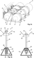
- Figs. 3a and 3b schematically illustrate a fastening device 2 according to embodiments.
- Fig. 3a shows the fastening devices 2 in a pre-engaged state.
- Fig. 3b shows the fastening device 2 in an engaged state.
- the fastening device 2 is a fastening device 2 for fastening a first and a second container 4', 4" to a structure of a vehicle 1.
- the fastening device 2 may be a fastening device of a gas fuel storage assembly 5 for a vehicle 1.
- the fastening device 2 may be a fastening device 2 as discussed above with reference to Fig.1 and with reference to Figs. 2a - 2c .
- Figs. 1 - 2c the fastening device 2 may be a fastening device 2 as discussed above with reference to Fig.1 and with reference to Figs. 2a - 2c .
- Figs. 1 - 2c the fastening device 2 may be a fastening device 2 as discussed above with reference to Fig.1 and with reference to Figs. 2a - 2c .
- the fastening device 2 comprises an elongated member 16 at least partly provided with external engagement members 18.
- the external engagement members 18 are threads and accordingly, the elongated member 16 may be a bolt or screw.
- the elongated member extends along an axis 19.
- the fastening device 2 further comprises a first abutment 20 arranged concentrically with the elongated member 16.
- the first abutment 20 is provided by the elongated member 16 in the form of at least part of an axial surface of a head 21 of the elongated member 16 being in the form of a threaded bolt.
- first abutment 20 may form part of a separate member, such as in the embodiments discussed below with reference to Figs. 5a - 5c .
- the fastening device 2 further comprises a displaceable member 22 connectable to a first band member 8 configured to extend at least partially around the first container 4' and to a second band member 10 configured to extend at least partially around the second container 4".
- the elongated member 16 extends through the displaceable member 22.
- the displaceable member 22 is displaceable along the axis 19 directly, or indirectly, by the elongated member 16 as it is displaced along the axis 19.
- the displaceable member 22 may be displaceable along the axis 19 by the first and second band members 8, 10 as they move with expanding and contracting of the first and/or second containers 4', 4".
- the fastening device 2 further comprises a guide arrangement 12.
- the guide arrangement 12 forms an anchor or attachment point of the fastening device 2 to a structure, such as a structure of a vehicle e.g., a bracket or a chassis. Accordingly, the guide arrangement 12 is connectable to a structure.
- the guide arrangement 12 comprises one part only.
- the guide arrangement 12 may comprise more than one part e.g., as in the embodiments discussed below with reference to Figs. 5a - 5c .
- the guide arrangement 12 comprises a second abutment 24.
- the guide arrangement 12 is provided with a through hole 26 concentrically with the axis 19 and the second abutment 24 extends around the through hole 26.
- the elongated member 16 extends through the through hole 26 of the guide arrangement 12. Thus, the elongated member 16 may be guided in the guide arrangement 12.
- the fastening device 2 further comprises a holed member 28 at least partly provided with internal engagement members 30.
- the holed member 28 is a nut and the internal engagement members 30 are threads.
- the external engagement members 18 of the elongated member 16 in the form of external threads are arranged to engage with the internal engagement members 30 of the holed member 28 in the form of internal threads, as shown in Fig. 3b .
- the fastening device 2 further comprises a resilient compressible member 32 positioned between the second abutment 24 and the holed member 28.
- the resilient compressible member 32 is schematically illustrated and may be for instance an elastomer member such as e.g. a rubber member but may be any other suitable compressible member.
- the elongated member 16 extends through the resilient compressible member 32.
- the elongated member 16 extends along the axis 19.
- the displaceable member 22, the guide arrangement 12, the resilient compressible member 32, and the holed member 28 are all aligned along the axis 19.
- the elongated member 16 extends through the displaceable member 22, at least partially through the guide arrangement 12, and through the resilient compressible member 32 for engagement between the external engagement members 18 of the elongated member 16 and the internal engagement members 30 of the holed member 28 in order to compress the resilient compressible member 32, see Fig. 3b .
- the fastening device 2 is shown in a pre-engaged state.
- the guide arrangement 12 is fastened to a structure (not shown), the first and second band members 8, 10 are positioned to extend at least partially around the first and second containers (not shown), and the elongated member 16 has been inserted through the displaceable member 22 and the through hole 26 of the guide arrangement 12 to extend into the resilient compressible member 32.
- the external engagement members 18 of the elongated member 16 and the internal engagement members 30 of the holed member 28 are ready to be engaged with each other.
- Fig. 3b the fastening device 2 is shown in an engaged state.
- the external engagement members 18 of the elongated member 16 and the internal engagement members 30 of the holed member 28 are engaged with each other i.e., in these embodiments, the threaded bolt 16 and the nut 28 have been tightened.
- first and second band members 8, 10 are tensioned around at least part of the first and second containers (not shown) by the displaceable member 22 having been displaced in a direction towards the holed member 28. Also, the resilient compressible member 32 has been compressed between the second abutment 24 and the holed member 28.
- the threaded bolt 16 is movable in relation to the displaceable member 22 and the guide arrangement 12 in a direction along the axis 19.
- the threaded bolt 16 engages with the nut 28 the first abutment 20 is pressed against the displaceable member 22 and the nut 28 presses the resilient compressible member 32 against the second abutment 24 thus, compressing the resilient compressible member 32.
- the resilient compressible member 32 via the bolt 16 indirectly applies a force to the displaceable member 22 that tensions the first and second band members 8, 10.
- the displaceable member 22 is biased by the resilient compressible member 32 to tension the first and second band members 8, 10.
- the physical properties of the resilient compressible member 32 and the degree of compression of the resilient compressible member 32 determines the force applied to the displaceable member 22 and the tension in the first and second band members 8, 10.
- Figs. 4a and 4b schematically illustrate a fastening device 2 according to embodiments.
- the fastening device 2 of these embodiments resembles in much the fastening device 2 of the Figs. 3a and 3b embodiments. Accordingly, in the following mainly the differences between the embodiments will be discussed.
- the fastening device 2 is a fastening device 2 for fastening a first and a second container to a structure of a vehicle.
- the fastening device 2 comprises: an elongated member 16 at least partly provided with external engagement members 18, a first abutment 20 arranged concentrically with the elongated member 16, a displaceable member 22 connectable to a first band member 8 configured to extend at least partially around the first container and to a second band member 10 configured to extend at least partially around the second container, a guide arrangement 12 comprising a second abutment 24, a holed member 28 at least partly provided with internal engagement members 30, and a resilient compressible member 32.
- the elongated member 16 extends along an axis 19 and the displaceable member 22, the guide arrangement 12, the resilient compressible member 32, and the holed member 28 are aligned along the axis 19.
- the elongated member 16 extends through the resilient compressible member 32, through the displaceable member 22, and at least partially through the guide arrangement 12 for engagement between the external engagement members 18 of the elongated member 16 and the internal engagement members 30 of the holed member 28 for compression of the resilient compressible member 32.
- the resilient compressible member 32 is positioned between the first abutment 20 and the displaceable member 22.
- the resilient compressible member 32 is schematically illustrated and may be for instance an elastomer member such as e.g. a rubber member but may be any other suitable compressible member.
- Fig. 4a the fastening device 2 is shown in a pre-engaged state.
- the guide arrangement 12 is fastened to a structure (not shown), the first and second band members 8, 10 are positioned to extend at least partially around the first and second containers (not shown), and the elongated member 16 has been inserted through the resilient compressible member 32, the displaceable member 22 and the through hole 26 of the guide arrangement 12.
- Fig. 4b the fastening device 2 is shown in an engaged state.
- the external engagement members 18 of the elongated member 16 and the internal engagement members 30 of the holed member 28 are engaged with each other i.e., in these embodiments, the threaded bolt 16 and the nut 28 have been tightened.
- first and second band members 8, 10 are tensioned around at least part of the first and second containers (not shown) by the displaceable member 22 having been displace in a direction towards the holed member 28. Also, the resilient compressible member 32 has been compressed between the first abutment 21 and the displaceable member 22.
- the threaded bolt 16 in the pre-engaged state, is movable in relation to the displaceable member 22 and the guide arrangement 12 in a direction along the axis 19.
- the first abutment 20 presses the resilient compressible member 32 against the displaceable member 22 and the nut 28 is pressed against the second abutment 24 thus, compressing the resilient compressible member 32.
- the resilient compressible member 32 by the tightened bolt 16, directly applies a force to the displaceable member 22 that tensions the first and second band members 8, 10.
- displaceable member 22 is biased by the resilient compressible member 32 to tension the first and second band members 8, 10.
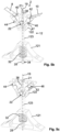
- Figs. 5a - 5c illustrate a fastening device 2 according to embodiments.
- Fig. 5a shows the fastening device 2 in an exploded view.
- Fig. 5b shows the fastening devices 2 in a pre-engaged state.
- Fig. 5c shows the fastening device 2 in an engaged state.
- the fastening device 2 is a fastening device 2 for fastening a first and a second container to a structure of a vehicle.
- the fastening device 2 may be a fastening device of a gas fuel storage assembly for a vehicle.
- the fastening device 2 may be a fastening device as discussed above with reference to Fig.1 and with reference to Figs. 2a - 2c .
- Figs. 1 - 2c the fastening device 2 may be a fastening device as discussed above with reference to Fig.1 and with reference to Figs. 2a - 2c .
- Figs. 1 - 2c the fastening device 2 may be a fastening device as discussed above with reference to Fig.1 and with reference to Figs. 2a - 2c .
- the fastening device 2 of these embodiments resembles in much the fastening device 2 of the Figs. 3a - 4b embodiments. Accordingly, in the following mainly the differences between the embodiments will be discussed.
- the fastening device 2 comprises: an elongated member 16 at least partly provided with external engagement members 18, a first abutment 20 arranged concentrically with the elongated member 16, a displaceable member 22 connectable to a first band member 8 configured to extend at least partially around the first container and to a second band member 10 configured to extend at least partially around the second container, a guide arrangement 12 comprising a second abutment 24, a holed member 28 at least partly provided with internal engagement members 30, and a resilient compressible member 32.
- the first and second band members 8, 10 are schematically indicated with broken lines in Fig. 5b .
- the holed member 28 is a pipe portion provided with internal engagement members 30 in the form of internal threads.
- the holed member 28 is rotationally locked in relation to the guide arrangement 12.
- the external engagement members 18 of the elongated member 16 may engage with the internal engagement members 30 of the holed member 30 without the holed member 28 rotating.
- the holed member 28 is rotationally locked but movable along the axis 19.
- the rotational lock may be achieved by corresponding formfitting contours of the holed member 28 and the guide arrangement 12.
- the rotational lock is achieved by the holed member 28, in the form of the pipe portion, having at least one flat external surface 34 and the guide arrangement 12 being provided with a hole 36 shaped such that the pipe portion snugly fits therein. In this manner, engagement the holed member 28 and the guide arrangement 12 in the hole 36 will prevent rotation of the holed member 28.
- Other shapes of the contours for rotationally locking the holed member 28 in relation to the guide arrangement 12 are possible, such as e.g. a triangular shape, a square shape, or a hexagonal shape.
- the elongated member 16 extends along an axis 19 and the displaceable member 22, the guide arrangement 12, the resilient compressible member 32, and the holed member 28 are aligned along the axis 19.
- the elongated member 16 extends through the displaceable member 22, at least partially through the guide arrangement 12, and through the resilient compressible member 32 for engagement between the external engagement members 18 of the elongated member 16 and the internal engagement members 30 of the holed member 28 for compression of the resilient compressible member 32.
- the resilient compressible member 32 is positioned between the second abutment 24 and the holed member 28.
- the resilient compressible member 32 comprises a helical spring and/or a coned-disc spring (Belleville disc washer spring).
- the resilient compressible member 32 may comprise an elastomer material, such as a rubber material.
- the choice of the resilient compressible member 32 may depend on the particular use case of the fastening device 2. Mentioned purely as examples, an elastomer material may provide a short compression distance and a comparatively low compression force in comparison with the helical spring. A helical spring may provide a long compression distance and a low compression force in comparison with a coned-disc spring that may provide a short compression distance with a high compression force.
- the fastening device 2 comprises a sleeve 38 arranged concentrically with the axis 19.
- the sleeve 38 comprises the first abutment 20.
- the sleeve 38 is arranged between a head portion 21 of the elongated member 16 and the displaceable member 22.
- the elongated member 16 extends through the sleeve 38 for the first abutment 20 to abut against the displaceable member 22 when the elongated member 16 engages with the holed member 28.
- the guide arrangement 12 may be comprised of one or more parts, such as only one part as in the embodiments of Figs. 3a - 4b .
- the guide arrangement 12 comprises a first guide member 121.
- the first guide member 121 is provided with a through hole 26 concentrically with the axis 19.
- the resilient compressible member 32 and the holed member 28 are arranged at least partially within the first guide member 121.
- the second abutment 24 extends around the through hole 26.
- the elongated member 16 extends through the through hole 26 of the first guide member 121 and through the resilient compressible member 32 to engage with the holed member 28.
- the second abutment 24 is arranged for the resilient compressible member 32 to abut thereagainst.
- the guide arrangement 12 further comprises a second guide member 122.
- the displaceable member 22 is arranged at least partially within the second guide member 122. In this manner, the displaceable member 22 may be securely arranged in the guide arrangement 12 and moreover, it may be guided in the guide arrangement 12.
- the guide arrangement 12 comprises a distance member 123 arranged between the first guide member 121 and the second guide member 122.
- the second guide member 122 may be positioned relative to the first guide member 121 such that the displaceable member 22 is arranged in suitable position for the first and second band members 8, 10 to extend at least partially around the first and second containers.
- the distance member 123 is hollow and the elongated member 16 extends through the distance member 123.
- the distance member 123 may also protect the elongated member 16 as it extends through the distance member 123, such that the elongated member 123 is not impeded in its movement in relation to the guide arrangement 12 during use of the fastening device 2. Movement of the elongated member 16 is caused by the first and second band members 8, 10 moving when they follow expansion and contraction of the first and second containers.
- the guide arrangement 12 may comprise only the first guide member 121 and the second guide member 122.
- a further alternative may be for the guide arrangement 12 to comprise only the first guide member 121 and the distance member 123.
- the displaceable member 22 comprises a first pin 40 and a second pin 42 on opposite sides of the axis 19.
- the first band member 8 is connectable to the displaceable member 22 via the first pin 40 and the second band member 10 is connectable to the displaceable member 22 via the second pin 42, as indicated in Fig. 5b .
- first and second band members 8 10 may be connected to the displaceable member 22.
- a pivotable connection between the displaceable member and the first and second band members 8, 10 may be achieved in this manner to ensure that the first and second band members 8, 10 align properly along a force component directed to/from the displaceable member 22.
- the second guide member 122 comprises a first slot 44 and a second slot 46. More specifically, a body 47 of the second guide member 122 is provided with the first and second slots 44, 46.
- the first pin 40 is slidably arranged in the first slot 44 and the second pin 42 is slidably arranged in the second slot 46.
- the first and second pins 40, 42 are moved in a controlled manner along the first and second slots 44, 46.
- the displaceable member 22 is displaced towards the holed member 28 and the first guide member 121. During this displacement, the first and second pins 40, 42 follow along the first and second slots 44, 46.
- first and second pins 40, 42 are slidably arranged in further slots 44', 46' provided in the second guide member 122.
- the displaceable member 22 comprises further first and second pins 48, 50 and linkage members 52 - 55 arranged between the first and second pins 40, 42 and the further first and second pins 48, 50, see Fig. 5a .
- first and second pins 40, 42 may be movable not only in parallel with the axis 19 but also in a direction perpendicularly to the axis 19.
- Fig. 5b the fastening device 2 is shown in a pre-engaged state.
- the guide arrangement 12 is fastened to a structure (not shown), the first and second band members 8, 10 are positioned to extend at least partially around the first and second containers (not shown), and the elongated member 16 has been inserted through the displaceable member 22 and the through hole 26 of the guide arrangement 12 to extend into the resilient compressible member 32.
- first and second pins 40, 42 are positioned at respective end portions of the first and second slots 44, 46.
- Fig. 5c the fastening device 2 is shown in an engaged state.
- the external engagement members 18 of the elongated member 16 and the internal engagement members 30 of the holed member 28 are engaged with each other.
- first and second band members 8, 10 are tensioned around at least part of the first and second containers (not shown) by the displaceable member 22 having been displace in a direction towards the first guide member 121 and the holed member 28. Also, the resilient compressible member 32 has been compressed between the second abutment 24 and the holed member 28.
- first and second pins 40, 42 are positioned at respective opposite end portions of the first and second slots 44, 46, compared to the positions of the pins 40, 42 in Fig. 5b . That is, the displaceable member 22 has been displaced in relation to the guide arrangement 12 and its second guide member 122.
- the guide arrangement 12 comprises at least two support surfaces 56, 58, see Fig. 5a , each of which is configured for supporting one of the first and second containers 4', 4", see e.g. Fig. 2c .
- the first and second containers 4', 4" are securely positioned in relation to the fastening device 2.
- the at least two support surfaces 56, 58 are configured for supporting the first and second containers 4', 4" e.g., by having a curved shape of the same or similar curvature as the first and second containers 4', 4" or by having any other shape suitable for supporting abutment against the first and second containers 4', 4".
- Fig. 6 illustrates a method 100 for assembly of a gas fuel storage assembly 5.
- the gas fuel storage assembly 5 may be a gas fuel storage assembly 5 as discussed above with referent to Figs. 2a - 2c . Accordingly, in the following reference is also made to Figs. 2a - 2c .
- the gas fuel storage assembly 5 comprises a fastening device 2 according to any one of aspects and/or embodiments discussed herein, such one of the fastening devices 2 discussed above with reference to Figs. 2a - 5c . Accordingly, in the following reference is also made to Figs. 2a -5c .
- the gas fuel storage assembly 5 further comprises at least a first container 4' and a second container 4", a bracket 6, a first band member 8, and a second band member 10 as disclosed herein.
- the method 100 comprises steps of:
- the step of securing 108 the first and second band members 8, 10 may comprise securing respective first ends 8', 10' of the first and second band members 8, 10 to the displaceable member 22 of the fastening device 2, such as to the first and second pins 40, 42.
- the opposite second ends 8", 10" of the first and second band members 8, 10 may be secured directly to the bracket 6 e.g., by being screwed thereto, or via dedicated attachment members connected to the bracket 6.
- Such dedicated attachment members being configured for holding ends of the first and second band members 8, 10.
- the step of engaging 110 the elongated member of the fastening device 2 with the holed member 28 of the fastening device 2 such that the resilient compressible member 32 of the fastening device 2 is compressed provides the clamping force to secure the first and second containers 4', 4" to the bracket 6.
- One or more of the steps of the method 100 may be performed in a different order than that listed above.
- the step of securing 108 the first and second band members 8, 10 may performed partially before the step of placing 106 the first and second band members 8, 10 and partially after the step of placing 106.
Abstract
The disclosure concerns a fastening device (2) for fastening a first and a second container (4', 4") to a structure of a vehicle (1), the fastening device (2) comprises: an elongated member (16) with external engagement members (18), a first abutment (20), a displaceable member (22), a guide arrangement (12), comprising a second abutment (24), a holed member (28), and a resilient compressible member (32). The elongated member (16) extends along an axis (19) and the displaceable member (22), the guide arrangement (12), the resilient compressible member (32), and the holed member (28) are aligned along the axis (19). The elongated member (16) extends through the displaceable member (22) and at least partially through the guide arrangement (12) for engagement between external engagement members (18) of the elongated member (16) and internal engagement members (30) of the holed member (28) for compression of the resilient compressible member (32).
Description
- The invention relates to a fastening device, a gas fuel storage assembly, and to a vehicle. The invention further relates to a method for assembly of a gas fuel storage assembly.
- A container may be connected to a structure with a fastening device that utilises a band arrangement connected to the structure. One or more bands of the band arrangement may extend at least partially around the container.
- One type of container connected to a structure in this manner may be a pressure vessel. For instance, the pressure vessel may be a pressure vessel for compressed gas and the structure may be a chassis of a vehicle, such as gas-powered vehicle.
- A tension in the one or more bands of the band arrangement around at least part of the container ensures that the container is securely held by the one or more bands and thus, securely attached by the fastening device to the structure. A clamping force provided by the fastening device causes the tension in the one or more bands.
- It may be difficult to provide an appropriate clamping force in a fastening device comprising one or more bands extending at least partially around a container.
- One common fastening device provides a rigid fixation. Using such a fastening device, it is possible to control an initial clamping force. However, in case of a pressure vessel, a diameter of the pressure vessel may vary i.e., the diameter increases as it is pressurised, and the diameter is reduced when the pressure is again reduced. Consequently, the clamping force and the tension in the one or more bands increase and decrease as well. When the at least one band is of low elasticity, the clamping force increase steeply and puts considerable additional stress on the fastening device.
- Such a steep increase in clamping force may be avoided in a different kind of known fastening device. This fastening device includes a spring and expands as a diameter of the container increases. Thus, the clamping force and the tension in the one or more bands only increases within a limited range of an initial force/tension as the container diameter increases.
- For instance,
WO 2018/030931 A1 discloses an example of a fuel tank attaching structure in a motor vehicle having at least one expandable and contractible fuel tank for storing compressed gas mounted thereon. The fastening device comprises at least one bracket fixed to a vehicle chassis for supporting the at least one fuel tank and at least one tensioning strap around the fuel tank. At least one tensioning device is acting between a first end and a second end of the tensioning strap whereby a spring load of the tensioning device applies a holding force of the tensioning strap to the gas tank regardless of whether the gas tank is expanded or not. The at least one tensioning device includes two fork-shaped fastening elements with spring means arranged in between shanks of the fork-shaped fastening elements. Assembly and mounting of the fuel tank attaching structure, in particular mounting of the fork-shaped fastening elements may be cumbersome and costly. - It is aimed at providing an alternative fastening device to the one disclosed in
WO 2018/030931 A1 . It would be advantageous to achieve a fastening device, which is of a less complicated structure than that disclosed inWO 2018/030931 A1 . In particular, it would be desirable to enable tensioning of a band around at least part of a container in an easily assembled fastening device. To better address one or more of these concerns, a fastening device, a gas fuel storage assembly, a vehicle, and/or a method having the features defined in one or more of the independent claims is provided. It is understood that all the various examples of the fastening device also apply for the gas fuel storage assembly, the vehicle and/or the method as disclosed herein, and vice versa. - According to an aspect, there is provided a fastening device for fastening a first and a second container to a structure of a vehicle. The fastening device comprises: an elongated member at least partly provided with external engagement members, a first abutment arranged concentrically with the elongated member, a displaceable member connectable to a first band member configured to extend at least partially around the first container and to a second band member configured to extend at least partially around the second container, a guide arrangement comprising a second abutment, a holed member at least partly provided with internal engagement members, and a resilient compressible member positioned between the first abutment and the displaceable member or between the second abutment and the holed member. The elongated member extends along an axis and the displaceable member, the guide arrangement, the resilient compressible member, and the holed member are aligned along the axis. The elongated member extends through the displaceable member and at least partially through the guide arrangement for engagement between the external engagement members of the elongated member and the internal engagement members of the holed member for compression of the resilient compressible member.
- Since the fastening device comprises the elongated member, the displaceable member connectable to the first and second band members, the guide arrangement, the holed member, and the resilient compressible member, and since the elongated member extends through the displaceable member and at least partially through the guide arrangement for engagement between the external engagement members of the elongated member and the internal engagement members of the holed member for compression of the resilient compressible member - the displaceable member is biased to tension the first and second band members by the resilient compressible member.
- Thus, the fastening device is configured to facilitate tensioning of the first and second band members at least partially around the first and second containers, respectively, via compression of the resilient compressible member by engagement between the external engagement members of the elongated member and the internal engagement members of the holed member.
- Moreover, the resilient compressible member not only provides a tension in the first and second band members, but due to the compressible property of the resilient compressible member, also ensures that a limited further strain is put on the first and second band members in case of an expansion of the first and second containers, which may occur if they are pressure vessels.
- The present fastening device provides easy tensioning of the first and second band members due to only the elongated member having to engaged with the holed member. This provides a cost-efficient way of fastening two containers to a structure of a vehicle.
- More specifically, the fastening device is utilised for fastening first and second containers to a structure of a vehicle. The structure of the vehicle may be a structure forming part of a chassis of the vehicle or a structure configured to be attached to the chassis of the vehicle.
- The first and second band members extend at least partially around respective of the first and second containers. In addition to being connectable to the displaceable member at respective first ends of the first and second band members, opposite second ends of the first and second band members are fixed in relation to the vehicle, such as by being connected to the structure of the vehicle.
- As mentioned above, in the fastening device, there is provided for engagement between the external engagement members of the elongated member and the internal engagement members of the holed member. Herein, for the sake of simplicity, reference is alternatively made to engagement between the elongated member and the holed member or the elongated member engaging with the holed member. Accordingly, such engagement or engaging is provided by the external engagement members of the elongated member and the internal engagement members of the holed member.
- The elongated member, when engaged with the holed member, is arranged such that the resilient compressible member is compressed or able to be compressed, either between the first abutment and the displaceable member or between the second abutment and the holed member. Thus, when the resilient compressible member is compressed, the first and second band members are tensioned and the first and second containers are securely fastened to the structure of the vehicle.
- The first and second containers may be pressure vessels. The pressure vessels may be made from metal, such as steel, or from a composite material, such as a carbon fibre reinforced material. In the latter case, the pressure vessels may expand less when under pressure than in the case of vessels made of metal, such as steel.
- The at least first and second containers may have a rounded shape, such as a generally cylindrical shape. The at least first and second containers may be configured for storing gas. Thus, the first container may be a first gas storage tank, and the second container may be a second gas storage tank. The at least first and second containers may be configured for storing CNG (Compressed Natural Gas).
- The term container, however, is to be interpreted broadly and may include a tank, a vessel, a housing of a vehicle component such as a battery, a utility box, etc.
- The displaceable member forms a link between the fastening device and the first and second band members. In order to fasten the first and second containers to the structure of a vehicle, the displaceable member is displaced along the axis when the elongated member is engaged with the holed member. Thus, the first and second band members are tightened at least partially around the first and second containers, respectively.
- Engagement of the elongated member with the holed member causes the displaceable member to be positioned in relation to the guide arrangement such that the first and second band members are tightened around at least part of the first and second containers.
- During mounting of the fastening device, engagement of the elongated member with the holed member causes the displaceable member to be displaced towards the holed member. This displacement of the displaceable member causes the first and second band members to provide a clamping force around the respective first and second containers.
- As mentioned above, the first and second band members are configured for extending at least partially around the first and second containers, respectively. Accordingly, the lengths of the first and second band members are determined by the relevant containers and optionally also by the relevant structure, to which the container is to be connected with the fastening device. Generally, larger containers may require longer band members than smaller containers.
- Tensions in the first and second band members ensure that the first and second containers are securely connected to the structure of the vehicle. The clamping force that causes the tensions in the first and second band members are provided by the resilient compressible member when the elongated member is engaged with the holed member.
- The elongated member may be a screw or a bolt or any other suitable elongated object that is provided with external engagement members and that is strong enough to withstand the forces caused by the resilient compressible member and the tension in the first and second band members during use of the fastening device. For instance, the elongated member may be made from metal, such as steel.
- The external engagement members of the elongated member may be e.g., threads or protrusions forming part of a ratchet mechanism or of a snap-fit mechanism.
- The holed member may be e.g. a nut or a pipe portion suitable for receiving at least partially therethrough a portion of the elongated member.
- The internal engagement members of the holed member may be e.g., threads or protrusions forming part of a ratchet mechanism or a snap-fit mechanism. That is, the internal engagement members are arranged at least partially inside a hole of the holed member.
- Accordingly, engagement between the external and internal engagement members may be achieved by tightening of external and internal threads or by pushing the elongated member into the holed member for engagement of a rachet mechanism or a snap-fit mechanism.
- Herein, the term abutment relates to that part of a member, an element, or similar that directly receives thrust or pressure. The thrust or pressure is caused by the compressed resilient compressible member and the tension in the first and second band members during use of the fastening device.
- The first abutment may form part of the elongated member or of a separate element, such as a sleeve arranged around the elongated member. The second abutment may form an integral part of the guide arrangement or be formed by an element included in the guide arrangement.
- The guide arrangement is configured to be secured to the structure of the vehicle. Thus, the guide arrangement forms an anchor or attachment point of the fastening device to the structure of a vehicle.
- For instance, the guide arrangement may be screwed or welded to the structure of the vehicle.
- As mentioned above, the elongated member extends through the displaceable member and at least partially through the guide arrangement. Accordingly, the guide arrangement forms an arrangement in relation to which, at least one other part of the fastening device, such as the elongated member, is guided.
- The guide arrangement may comprise more than one separate member or part, which separate members or parts are assembled to form the guide arrangement.
- The resilient compressible member may comprise any suitable compressible member for tensioning the first and second band members and for absorbing possible expansion of the first and second containers. The resilient compressible member may comprise one or more of a compression spring, coned-disc spring (Belleville washer), or an elastomer member such as e.g. a rubber tube portion.
- As mentioned above, when the external engagement members of the elongated member engage with the internal engagement members of the holed member, the resilient compressible member is compressed.
- During use of the fastening device, the resilient compressible member is compressed between the first abutment and the displaceable member or between the second abutment and the holed member. Thus, the resilient compressible member is configured to directly or indirectly apply a force to the displaceable member to tension the first and second band members.
- The particular clamping force to be provided by the resilient compressible member is determined for each particular construction case and depends inter alia on the relevant containers to be fastened by the fastening device and under what operating conditions the fastening device is used. Specifically, the reduction in length of the resilient compressible member and the force constant of the resilient compressible member determine the clamping force.
- According to embodiments, the guide arrangement may comprise a first guide member, being provided with a through hole concentrically with the axis, wherein the second abutment may extend around the through hole, and wherein the resilient compressible member and the holed member may be arranged at least partially within the first guide member. In this manner, the elongated member may extend through the through hole of the first guide member and through the resilient compressible member to engage with the holed member. Moreover, the resilient compressible member and the holed member may thus, be conveniently arranged at least partially within the guide arrangement.
- According to embodiments, the guide arrangement may comprise a second guide member, and the displaceable member may be arranged at least partially within the second guide member. In this manner, the guide arrangement may be provided for guiding the displaceable member.
- According to embodiments, the fastening device may comprise a sleeve arranged concentrically with the axis, and wherein the sleeve comprises the first abutment. In this manner, the elongated member may extend through the sleeve for the first abutment to be moved in a direction towards the displaceable member when the elongated member engages with the holed member.
- According to embodiments, the displaceable member may comprise a first pin and a second pin on opposite sides of the axis, and the first band member may be connectable to the displaceable member via the first pin and the second band member may be connectable to the displaceable member via the second pin. In this manner, there may be provided for a convenient connection between the fastening device and the first and second band members. Moreover, the first and second pins may provide for a pivotable connection between the displaceable member and the first and second band members. Such a pivotable connection may ensure that the first and second band members align properly along a force component directed to/from the displaceable member. The first and second band members may thus, not be subjected to bending load.
- According to embodiments, the second guide member may comprise a first slot and a second slot, wherein the first pin may be slidably arranged in the first slot, and wherein the second pin may be slidably arranged in the second slot. In this manner, movement of the first and second pins and accordingly, also movement of the first and second band members may be controlled along the first and second slots as the displaceable member is displaced in relation to the second guide member when the elongated member engages with the holed member to tension the first and second band members.
- Moreover, since during use of the fastening device, the first and second band members are connected to the first and second pins, and since the first and second pins are arranged in the first and second slots, the second guide member is prevented by the first and second band members from rotating in relation to the first guide member.
- According to embodiments, the guide arrangement may comprise at least two support surfaces each of which is configured for supporting one of the first and second containers. In this manner, the first and second containers may be securely positioned in relation to the fastening device when in use for fastening the containers to the structure of a vehicle.
- According to embodiments, the holed member may be rotationally locked in relation to the guide arrangement. In this manner, engagement between the external engagement members of the elongated member and the internal engagement members of the holed member may be facilitated. In particular, when the external and internal engagement members comprise threads such engagement of the elongated member in the holed member may be facilitated.
- According to a further aspect, there is provided a gas fuel storage assembly comprising at least a first container and a second container configured for storing gas, a bracket, a first band member, a second band member, and a fastening device according to any one of aspects and/or embodiments discussed herein, wherein the first and second band members and the fastening device secure the first and second containers to the bracket.
- Since the herein discussed fastening device secures the first and second containers to the bracket, the gas fuel storage assembly provides for easily tensioning of the first and second band members at least partially around first and second containers configured for storing gas while also limiting further strain in the first and second band members when the first and second containers expand. Thus, a cost-efficient way of securing the first and second containers to the bracket is provided.
- According to this aspect, the first and second containers may be a first gas storage tank and a second gas storage tank. The gas stored in such gas storage tanks may be compressed gas, such as CNG (Compressed Natural Gas) used as fuel in a combustion engine.
- According to a further aspect, there is provided a vehicle comprising a chassis and a gas fuel storage assembly according to any one of aspects and/or embodiments discussed herein connected to the chassis.
- Since the vehicle comprises the herein discussed gas fuel storage assembly, which in turn comprises the herein discussed fastening device, there is provided for easily tensioning of the first and second band members at least partially around the first and second containers while also limiting further strain in the first and second band members when the first and second containers expand. Thus, a cost-efficient way of securing the first and second containers to the vehicle is provided.
- According to a further aspect, there is provided a method for assembly of a gas fuel storage assembly comprising at least a first container and a second container configured for storing gas, a bracket, a first band member, a second band member, and a fastening device according to any one of aspects and/or embodiments discussed herein. The method comprises steps of:
- securing the guide arrangement of the fastening device to the bracket,
- positioning the first and second containers against the bracket,
- placing the first and second band members to extend at least partially around the first and second containers,
- securing the first and second band members to the fastening device and to the bracket, and engaging the elongated member of the fastening device with the holed member of the fastening device such that the resilient compressible member of the fastening device is compressed.
- Thus, a method is provided that ensures a cost-efficient way of assembling a gas storage tank assembly, such as for securing first and second gas storage tanks to the bracket.
- The bracket may form part of a chassis of a vehicle or may be mounted to a chassis of a vehicle. The vehicle may be a vehicle as discussed herein.
- One or more steps of the method may be performed in a different order than listed above.
- Further features of, and advantages with, the invention will become apparent when studying the appended claims and the following detailed description.
- Various aspects and/or embodiments of the invention, including its particular features and advantages, will be readily understood from the example embodiments discussed in the following detailed description and the accompanying drawings, in which:
-
Fig. 1 illustrates a vehicle according to embodiments, -
Figs. 2a - 2c illustrate a gas fuel storage assembly according to embodiments, -
Figs. 3a and 3b schematically illustrate a fastening device according to embodiments, -
Figs. 4a and 4b schematically illustrate a fastening device according to embodiments, -
Figs. 5a - 5c illustrate a fastening device according to embodiments, and -
Fig. 6 illustrates a method for assembly of a gas fuel storage assembly. - Aspects and/or embodiments of the invention will now be described more fully. Like numbers refer to like elements throughout. Well-known functions or constructions will not necessarily be described in detail for brevity and/or clarity. It is understood that all the various examples of the fastening device also apply for the gas fuel storage assembly, the vehicle, and/or the method as disclosed herein, and vice versa.
-
Fig. 1 illustrates avehicle 1 according to embodiments. - The
vehicle 1 may be any kind of vehicle configured for land-based propulsion, such as e.g., a bus, a truck, a heavy truck, a car, or a train. InFig. 1 , thevehicle 1 is illustrated as a heavy load vehicle in the form of a truck. - The
vehicle 1 comprises at least twocontainers 4. Thecontainers 4 are secured to achassis 3 of thevehicle 1 by at least onefastening device 2 according to any one of aspects and/or embodiments discussed herein. The at least twocontainers 4 as shown inFig. 1 may comprise the first container (4') and the second container (4") as shown in the embodiments discussed below with reference toFigs. 2a-5c . - In the illustrated embodiments, the
containers 4 are secured to thechassis 3 with twofastening devices 2. Each of thefastening devices 2 may be afastening device 2 in accordance with one of embodiments discussed below with reference toFigs. 2a - 5c . - Moreover, the
vehicle 1 comprises thechassis 3 and according to some aspects and/or embodiments, a gasfuel storage assembly 5 according to any one of aspects and/or embodiments discussed herein connected to thechassis 3. - In such aspects/embodiments, the at least two
containers 4 may be gas storage tanks configured for receiving and accommodating compressed gas and for providing gas to a combustion engine of thevehicle 1. - Embodiments of the
gas storage assembly 5 are discussed below with reference toFigs. 2a -2c . - As discussed herein, the
fastening device 2 provides easy fastening ofcontainers vehicle 1 as well as being able to absorb an increase in container diameter, caused by an internal gas pressure in thecontainers containers - The gas in the
containers vehicle 1. Alternatively, the gas may be compressed air utilised e.g., in a brake system of thevehicle 1. - A further alternative is that the gas in the
containers vehicle 1 or to be supplied to a fuel cell for a reaction therein to provide electricity for anelectrical vehicle 1. - According to alternative embodiments, the
containers cassis 3 of thevehicle 1, such as battery and/or utility boxes. - The number of
fastening devices 2 used for connecting thecontainers chassis 3 may be selected in order to provide a secure fastening of therelevant containers containers -
Figs. 2a - 2c illustrate a gasfuel storage assembly 5 according to embodiments.Fig. 2a shows a side view of the gasfuel storage assembly 5,Fig. 2b shows an isometric view of the gasfuel storage assembly 5, andFig. 2c shows a further isometric view of the gasfuel storage assembly 5. - The gas
fuel storage assembly 5 is configured for being connected to a vehicle. - In
Figs. 2a - 2c , the gasfuel storage assembly 5 is shown connected to a vehicle, such as acassis 3 of a vehicle. The vehicle may be avehicle 1 as discussed above with reference toFig. 1 . - The gas
fuel storage assembly 5 comprises at least a first container 4' and asecond container 4" configured for storing gas, abracket 6, afirst band member 8, asecond band member 10, and afastening device 2 according to any one of aspects and/or embodiments discussed herein. - The
bracket 6 is provided with holes such that it can be mounted with e.g., rivets or screws to a structure of a vehicle, such as thechassis 3 of the vehicle. In this manner, the gasfuel storage assembly 5 may be configured for being connected to a vehicle. - The
bracket 6 may be seen to form part of a structure of thevehicle 1. A further alternative may be for thechassis 3 of thevehicle 1 to comprise thebracket 6. - In the illustrated embodiments, the
bracket 6 is substantially L-shaped. However, the bracket may have any other shape that lends it suitable for being connected to a structure of a vehicle. - The first and
second band members fastening device 2 secure the first andsecond containers 4', 4" to thebracket 6. - Mentioned purely as examples, the first and
second band members second containers 4', 4" against thebracket 6. - Depending on the size of the relevant gas
fuel storage assembly 5, it may comprise more than onebracket 6,first band member 8,second band member 10, andfastening device 2. In the illustrated embodiments, the gasfuel storage assembly 5 comprises three brackets, first band members, second band members, and fastening devices. - The first and
second containers 4', 4" may form first and second gas storage tanks. - The gas stored in the
containers 4', 4" may be compressed gas, such as CNG or biogas used as fuel in a combustion engine. - The
fastening device 2 may be afastening device 2 as discussed below with reference toFigs. 3a - 5c . - According to embodiments of the gas
fuel storage assembly 5, aguide arrangement 12 of thefastening device 2 may be secured to thebracket 6 between the first andsecond containers 4', 4". In this manner, the first andsecond band members fastening device 2 to extend at least partially around respective of the first andsecond containers 4', 4". - Moreover, in this manner, the
fastening device 2 may be secured to the bracket via the guide arrangement. - See further below with reference to
Figs. 3a - 5c concerning various embodiments of theguide arrangement 12 of thefastening device 2. - According to embodiments, of the gas
fuel storage assembly 5, the first andsecond band members bracket 6. In this manner, thefastening device 2 may be utilised for tightening the first andsecond band members second containers 4', 4". - As mentioned above, the first and
second band members second containers 4', 4". Respective first ends 8', 10' of the first andsecond band members fastening device 2. Opposite second ends 8", 10" of the first andsecond band members bracket 6. - For instance, each of the first and second band ends 8', 8", 10', 10" of the first and
second band members fastening device 2 and thebracket 6. - Tensions in the first and
second band members second containers 4', 4" are securely connected to thebracket 6. - The gas
fuel storage assembly 5 may comprise members for securely positioning thecontainers 4', 4" against thebracket 6 and/or against the first andsecond band members band 14', 14" may be provided around each of the first andsecond containers 4', 4", between thebracket 6 and the first andsecond containers 4', 4" and between respective of the first andsecond band members second containers 4', 4". - In the embodiments of
Figs. 2a - 2c , eachfastening devices 2 is illustrated as afastening device 2 in accordance with the embodiments ofFigs. 5a - 5c . Alternatively, thefastening devices 2 may be fasteningdevices 2 in accordance with embodiments ofFigs. 3a and 3b . or the embodiments ofFigs. 4a and 4b . -
Figs. 3a and 3b schematically illustrate afastening device 2 according to embodiments.Fig. 3a shows thefastening devices 2 in a pre-engaged state.Fig. 3b shows thefastening device 2 in an engaged state. - The
fastening device 2 is afastening device 2 for fastening a first and asecond container 4', 4" to a structure of avehicle 1. For instance, thefastening device 2 may be a fastening device of a gasfuel storage assembly 5 for avehicle 1. - Accordingly, the
fastening device 2 may be afastening device 2 as discussed above with reference toFig.1 and with reference toFigs. 2a - 2c . Thus, in the following reference is also made toFigs. 1 - 2c . - The
fastening device 2 comprises anelongated member 16 at least partly provided withexternal engagement members 18. In the illustrated embodiments, theexternal engagement members 18 are threads and accordingly, theelongated member 16 may be a bolt or screw. The elongated member extends along anaxis 19. - The
fastening device 2 further comprises afirst abutment 20 arranged concentrically with theelongated member 16. In the illustrated embodiments, thefirst abutment 20 is provided by theelongated member 16 in the form of at least part of an axial surface of ahead 21 of theelongated member 16 being in the form of a threaded bolt. - Alternatively, the
first abutment 20 may form part of a separate member, such as in the embodiments discussed below with reference toFigs. 5a - 5c . - The
fastening device 2 further comprises adisplaceable member 22 connectable to afirst band member 8 configured to extend at least partially around the first container 4' and to asecond band member 10 configured to extend at least partially around thesecond container 4". - The
elongated member 16 extends through thedisplaceable member 22. Thedisplaceable member 22 is displaceable along theaxis 19 directly, or indirectly, by theelongated member 16 as it is displaced along theaxis 19. Moreover, thedisplaceable member 22 may be displaceable along theaxis 19 by the first andsecond band members second containers 4', 4". - The
fastening device 2 further comprises aguide arrangement 12. Theguide arrangement 12 forms an anchor or attachment point of thefastening device 2 to a structure, such as a structure of a vehicle e.g., a bracket or a chassis. Accordingly, theguide arrangement 12 is connectable to a structure. - In the illustrated embodiments, the
guide arrangement 12 comprises one part only. Alternatively, theguide arrangement 12 may comprise more than one part e.g., as in the embodiments discussed below with reference toFigs. 5a - 5c . - The
guide arrangement 12 comprises asecond abutment 24. - The
guide arrangement 12 is provided with a throughhole 26 concentrically with theaxis 19 and thesecond abutment 24 extends around the throughhole 26. - The
elongated member 16 extends through the throughhole 26 of theguide arrangement 12. Thus, theelongated member 16 may be guided in theguide arrangement 12. - The
fastening device 2 further comprises a holedmember 28 at least partly provided withinternal engagement members 30. - In the illustrated embodiments, the holed
member 28 is a nut and theinternal engagement members 30 are threads. - Thus, the
external engagement members 18 of theelongated member 16 in the form of external threads are arranged to engage with theinternal engagement members 30 of the holedmember 28 in the form of internal threads, as shown inFig. 3b . - The
fastening device 2 further comprises a resilientcompressible member 32 positioned between thesecond abutment 24 and the holedmember 28. The resilientcompressible member 32 is schematically illustrated and may be for instance an elastomer member such as e.g. a rubber member but may be any other suitable compressible member. - The
elongated member 16 extends through the resilientcompressible member 32. - As mentioned above, the
elongated member 16 extends along theaxis 19. Thedisplaceable member 22, theguide arrangement 12, the resilientcompressible member 32, and the holedmember 28 are all aligned along theaxis 19. - The
elongated member 16 extends through thedisplaceable member 22, at least partially through theguide arrangement 12, and through the resilientcompressible member 32 for engagement between theexternal engagement members 18 of theelongated member 16 and theinternal engagement members 30 of the holedmember 28 in order to compress the resilientcompressible member 32, seeFig. 3b . - As mentioned above, in
Fig. 3a , thefastening device 2 is shown in a pre-engaged state. Theguide arrangement 12 is fastened to a structure (not shown), the first andsecond band members elongated member 16 has been inserted through thedisplaceable member 22 and the throughhole 26 of theguide arrangement 12 to extend into the resilientcompressible member 32. - Thus, the
external engagement members 18 of theelongated member 16 and theinternal engagement members 30 of the holedmember 28 are ready to be engaged with each other. In these embodiments that means tightening theelongated member 16 in the holedmember 28 i.e., tightening the threadedbolt 16 in thenut 28. - In
Fig. 3b , thefastening device 2 is shown in an engaged state. Theexternal engagement members 18 of theelongated member 16 and theinternal engagement members 30 of the holedmember 28 are engaged with each other i.e., in these embodiments, the threadedbolt 16 and thenut 28 have been tightened. - Thus, the first and
second band members displaceable member 22 having been displaced in a direction towards the holedmember 28. Also, the resilientcompressible member 32 has been compressed between thesecond abutment 24 and the holedmember 28. - More specifically, in the pre-engaged state, the threaded
bolt 16 is movable in relation to thedisplaceable member 22 and theguide arrangement 12 in a direction along theaxis 19. As the threadedbolt 16 engages with thenut 28, thefirst abutment 20 is pressed against thedisplaceable member 22 and thenut 28 presses the resilientcompressible member 32 against thesecond abutment 24 thus, compressing the resilientcompressible member 32. - Accordingly, the resilient
compressible member 32, via thebolt 16 indirectly applies a force to thedisplaceable member 22 that tensions the first andsecond band members displaceable member 22 is biased by the resilientcompressible member 32 to tension the first andsecond band members - The physical properties of the resilient
compressible member 32 and the degree of compression of the resilientcompressible member 32 determines the force applied to thedisplaceable member 22 and the tension in the first andsecond band members -
Figs. 4a and 4b schematically illustrate afastening device 2 according to embodiments. - The
fastening device 2 of these embodiments resembles in much thefastening device 2 of theFigs. 3a and 3b embodiments. Accordingly, in the following mainly the differences between the embodiments will be discussed. - Again, the
fastening device 2 is afastening device 2 for fastening a first and a second container to a structure of a vehicle. Again, thefastening device 2 comprises: anelongated member 16 at least partly provided withexternal engagement members 18, afirst abutment 20 arranged concentrically with theelongated member 16, adisplaceable member 22 connectable to afirst band member 8 configured to extend at least partially around the first container and to asecond band member 10 configured to extend at least partially around the second container, aguide arrangement 12 comprising asecond abutment 24, a holedmember 28 at least partly provided withinternal engagement members 30, and a resilientcompressible member 32. - Again, the
elongated member 16 extends along anaxis 19 and thedisplaceable member 22, theguide arrangement 12, the resilientcompressible member 32, and the holedmember 28 are aligned along theaxis 19. Again, theelongated member 16 extends through the resilientcompressible member 32, through thedisplaceable member 22, and at least partially through theguide arrangement 12 for engagement between theexternal engagement members 18 of theelongated member 16 and theinternal engagement members 30 of the holedmember 28 for compression of the resilientcompressible member 32. - In these embodiments, the resilient
compressible member 32 is positioned between thefirst abutment 20 and thedisplaceable member 22. The resilientcompressible member 32 is schematically illustrated and may be for instance an elastomer member such as e.g. a rubber member but may be any other suitable compressible member. - In
Fig. 4a , thefastening device 2 is shown in a pre-engaged state. Theguide arrangement 12 is fastened to a structure (not shown), the first andsecond band members elongated member 16 has been inserted through the resilientcompressible member 32, thedisplaceable member 22 and the throughhole 26 of theguide arrangement 12. - Thus, the
external engagement members 18 of theelongated member 16 and theinternal engagement members 30 of the holedmember 28 are ready to be engaged with each other. - In
Fig. 4b , thefastening device 2 is shown in an engaged state. Theexternal engagement members 18 of theelongated member 16 and theinternal engagement members 30 of the holedmember 28 are engaged with each other i.e., in these embodiments, the threadedbolt 16 and thenut 28 have been tightened. - Thus, the first and
second band members displaceable member 22 having been displace in a direction towards the holedmember 28. Also, the resilientcompressible member 32 has been compressed between thefirst abutment 21 and thedisplaceable member 22. - More specifically, in the pre-engaged state, the threaded
bolt 16 is movable in relation to thedisplaceable member 22 and theguide arrangement 12 in a direction along theaxis 19. As the threadedbolt 16 engages with thenut 28, thefirst abutment 20 presses the resilientcompressible member 32 against thedisplaceable member 22 and thenut 28 is pressed against thesecond abutment 24 thus, compressing the resilientcompressible member 32. Accordingly, the resilientcompressible member 32, by the tightenedbolt 16, directly applies a force to thedisplaceable member 22 that tensions the first andsecond band members - Again, the
displaceable member 22 is biased by the resilientcompressible member 32 to tension the first andsecond band members -
Figs. 5a - 5c illustrate afastening device 2 according to embodiments.Fig. 5a shows thefastening device 2 in an exploded view.Fig. 5b shows thefastening devices 2 in a pre-engaged state.Fig. 5c shows thefastening device 2 in an engaged state. - The
fastening device 2 is afastening device 2 for fastening a first and a second container to a structure of a vehicle. For instance, thefastening device 2 may be a fastening device of a gas fuel storage assembly for a vehicle. - Accordingly, the
fastening device 2 may be a fastening device as discussed above with reference toFig.1 and with reference toFigs. 2a - 2c . Thus, in the following reference is also made toFigs. 1 - 2c . - The
fastening device 2 of these embodiments resembles in much thefastening device 2 of theFigs. 3a - 4b embodiments. Accordingly, in the following mainly the differences between the embodiments will be discussed. - Again, the
fastening device 2 comprises: anelongated member 16 at least partly provided withexternal engagement members 18, afirst abutment 20 arranged concentrically with theelongated member 16, adisplaceable member 22 connectable to afirst band member 8 configured to extend at least partially around the first container and to asecond band member 10 configured to extend at least partially around the second container, aguide arrangement 12 comprising asecond abutment 24, a holedmember 28 at least partly provided withinternal engagement members 30, and a resilientcompressible member 32. - The first and
second band members Fig. 5b . - In these embodiments, the holed
member 28 is a pipe portion provided withinternal engagement members 30 in the form of internal threads. - The holed
member 28 is rotationally locked in relation to theguide arrangement 12. Thus, theexternal engagement members 18 of theelongated member 16 may engage with theinternal engagement members 30 of the holedmember 30 without the holedmember 28 rotating. - Accordingly, the holed
member 28 is rotationally locked but movable along theaxis 19. - As an example, the rotational lock may be achieved by corresponding formfitting contours of the holed
member 28 and theguide arrangement 12. For example, in the embodiment shown inFig. 5a-5c , the rotational lock is achieved by the holedmember 28, in the form of the pipe portion, having at least one flatexternal surface 34 and theguide arrangement 12 being provided with ahole 36 shaped such that the pipe portion snugly fits therein. In this manner, engagement the holedmember 28 and theguide arrangement 12 in thehole 36 will prevent rotation of the holedmember 28. Other shapes of the contours for rotationally locking the holedmember 28 in relation to theguide arrangement 12 are possible, such as e.g. a triangular shape, a square shape, or a hexagonal shape. - Again, the
elongated member 16 extends along anaxis 19 and thedisplaceable member 22, theguide arrangement 12, the resilientcompressible member 32, and the holedmember 28 are aligned along theaxis 19. Again, theelongated member 16 extends through thedisplaceable member 22, at least partially through theguide arrangement 12, and through the resilientcompressible member 32 for engagement between theexternal engagement members 18 of theelongated member 16 and theinternal engagement members 30 of the holedmember 28 for compression of the resilientcompressible member 32. - Like in the embodiments of
Figs. 3a and 3b , the resilientcompressible member 32 is positioned between thesecond abutment 24 and the holedmember 28. - According to these embodiments, the resilient
compressible member 32 comprises a helical spring and/or a coned-disc spring (Belleville disc washer spring). - Alternatively, the resilient
compressible member 32 may comprise an elastomer material, such as a rubber material. - The choice of the resilient
compressible member 32 may depend on the particular use case of thefastening device 2. Mentioned purely as examples, an elastomer material may provide a short compression distance and a comparatively low compression force in comparison with the helical spring. A helical spring may provide a long compression distance and a low compression force in comparison with a coned-disc spring that may provide a short compression distance with a high compression force. - In these embodiments, the
fastening device 2 comprises asleeve 38 arranged concentrically with theaxis 19. Thesleeve 38 comprises thefirst abutment 20. Thesleeve 38 is arranged between ahead portion 21 of theelongated member 16 and thedisplaceable member 22. - Thus, the
elongated member 16 extends through thesleeve 38 for thefirst abutment 20 to abut against thedisplaceable member 22 when theelongated member 16 engages with the holedmember 28. - The
guide arrangement 12 may be comprised of one or more parts, such as only one part as in the embodiments ofFigs. 3a - 4b . - In the embodiments of
Figs. 5a - 5b , theguide arrangement 12 comprises afirst guide member 121. Thefirst guide member 121 is provided with a throughhole 26 concentrically with theaxis 19. The resilientcompressible member 32 and the holedmember 28 are arranged at least partially within thefirst guide member 121. Thesecond abutment 24 extends around the throughhole 26. - The
elongated member 16 extends through the throughhole 26 of thefirst guide member 121 and through the resilientcompressible member 32 to engage with the holedmember 28. - The
second abutment 24 is arranged for the resilientcompressible member 32 to abut thereagainst. - The
guide arrangement 12 further comprises asecond guide member 122. Thedisplaceable member 22 is arranged at least partially within thesecond guide member 122. In this manner, thedisplaceable member 22 may be securely arranged in theguide arrangement 12 and moreover, it may be guided in theguide arrangement 12. - According to these embodiments, the
guide arrangement 12 comprises adistance member 123 arranged between thefirst guide member 121 and thesecond guide member 122. In this manner, thesecond guide member 122 may be positioned relative to thefirst guide member 121 such that thedisplaceable member 22 is arranged in suitable position for the first andsecond band members - In the illustrated embodiments, the
distance member 123 is hollow and theelongated member 16 extends through thedistance member 123. - The
distance member 123 may also protect theelongated member 16 as it extends through thedistance member 123, such that theelongated member 123 is not impeded in its movement in relation to theguide arrangement 12 during use of thefastening device 2. Movement of theelongated member 16 is caused by the first andsecond band members - According to alternative embodiments, the
guide arrangement 12 may comprise only thefirst guide member 121 and thesecond guide member 122. A further alternative may be for theguide arrangement 12 to comprise only thefirst guide member 121 and thedistance member 123. - The
displaceable member 22 comprises afirst pin 40 and asecond pin 42 on opposite sides of theaxis 19. Thefirst band member 8 is connectable to thedisplaceable member 22 via thefirst pin 40 and thesecond band member 10 is connectable to thedisplaceable member 22 via thesecond pin 42, as indicated inFig. 5b . - Thus, the first and
second band members 8 10 may be connected to thedisplaceable member 22. A pivotable connection between the displaceable member and the first andsecond band members second band members displaceable member 22. - The
second guide member 122 comprises afirst slot 44 and asecond slot 46. More specifically, abody 47 of thesecond guide member 122 is provided with the first andsecond slots - The
first pin 40 is slidably arranged in thefirst slot 44 and thesecond pin 42 is slidably arranged in thesecond slot 46. - Accordingly, as the
displaceable member 22 is moved in relation to theguide arrangement 12 and thesecond guide member 122, the first andsecond pins second slots - More specifically, as the
elongated member 16 engages with the holedmember 28 and the resilientcompressible member 32 is compressed, thedisplaceable member 22 is displaced towards the holedmember 28 and thefirst guide member 121. During this displacement, the first andsecond pins second slots - In the illustrated embodiments, the first and
second pins second guide member 122. - Although not limiting to the general idea of utilising first and
second pins second band members displaceable member 22, in the illustrated embodiments, thedisplaceable member 22 comprises further first andsecond pins 48, 50 and linkage members 52 - 55 arranged between the first andsecond pins second pins 48, 50, seeFig. 5a . - In this manner, the first and
second pins axis 19 but also in a direction perpendicularly to theaxis 19. - In
Fig. 5b , thefastening device 2 is shown in a pre-engaged state. Theguide arrangement 12 is fastened to a structure (not shown), the first andsecond band members elongated member 16 has been inserted through thedisplaceable member 22 and the throughhole 26 of theguide arrangement 12 to extend into the resilientcompressible member 32. - Thus, the
external engagement members 18 of theelongated member 16 and theinternal engagement members 30 of the holedmember 28 are ready to be engaged with each other. - Note that the first and
second pins second slots - In
Fig. 5c , thefastening device 2 is shown in an engaged state. Theexternal engagement members 18 of theelongated member 16 and theinternal engagement members 30 of the holedmember 28 are engaged with each other. - Thus, the first and
second band members displaceable member 22 having been displace in a direction towards thefirst guide member 121 and the holedmember 28. Also, the resilientcompressible member 32 has been compressed between thesecond abutment 24 and the holedmember 28. - Note that the first and
second pins second slots pins Fig. 5b . That is, thedisplaceable member 22 has been displaced in relation to theguide arrangement 12 and itssecond guide member 122. - The
guide arrangement 12 comprises at least two support surfaces 56, 58, seeFig. 5a , each of which is configured for supporting one of the first andsecond containers 4', 4", see e.g.Fig. 2c . Thus, in use of thefastening device 2, the first andsecond containers 4', 4" are securely positioned in relation to thefastening device 2. - The at least two support surfaces 56, 58 are configured for supporting the first and
second containers 4', 4" e.g., by having a curved shape of the same or similar curvature as the first andsecond containers 4', 4" or by having any other shape suitable for supporting abutment against the first andsecond containers 4', 4". -
Fig. 6 illustrates amethod 100 for assembly of a gasfuel storage assembly 5. - The gas
fuel storage assembly 5 may be a gasfuel storage assembly 5 as discussed above with referent toFigs. 2a - 2c . Accordingly, in the following reference is also made toFigs. 2a - 2c . - The gas
fuel storage assembly 5 comprises afastening device 2 according to any one of aspects and/or embodiments discussed herein, such one of thefastening devices 2 discussed above with reference toFigs. 2a - 5c . Accordingly, in the following reference is also made toFigs. 2a -5c . - The gas
fuel storage assembly 5 further comprises at least a first container 4' and asecond container 4", abracket 6, afirst band member 8, and asecond band member 10 as disclosed herein. - The
method 100 comprises steps of: - securing 102 the
guide arrangement 12 of thefastening device 2 to thebracket 6, - positioning 104 the first and
second containers 4', 4" against thebracket 6, - placing 106 the first and
second band members second containers 4', 4", - securing 108 the first and
second band members fastening device 2 and to thebracket 6, and - engaging 110 the elongated member of the
fastening device 2 with the holedmember 28 of thefastening device 2 such that the resilientcompressible member 32 of thefastening device 2 is compressed. - The step of securing 108 the first and
second band members second band members displaceable member 22 of thefastening device 2, such as to the first andsecond pins second band members bracket 6 e.g., by being screwed thereto, or via dedicated attachment members connected to thebracket 6. Such dedicated attachment members being configured for holding ends of the first andsecond band members - The step of engaging 110 the elongated member of the
fastening device 2 with the holedmember 28 of thefastening device 2 such that the resilientcompressible member 32 of thefastening device 2 is compressed provides the clamping force to secure the first andsecond containers 4', 4" to thebracket 6. - One or more of the steps of the
method 100 may be performed in a different order than that listed above. For instance, the step of securing 108 the first andsecond band members second band members - It is to be understood that the foregoing is illustrative of various example embodiments and that the invention is defined only by the appended claims. A person skilled in the art will realize that the example embodiments may be modified, and that different features of the example embodiments may be combined to create embodiments other than those described herein, without departing from the scope of the invention, as defined by the appended claims.
Claims (15)
- A fastening device (2) for fastening a first and a second container (4', 4") to a structure of a vehicle (1), the fastening device (2) comprising:an elongated member (16) at least partly provided with external engagement members (18),a first abutment (20) arranged concentrically with the elongated member (16),a displaceable member (22) connectable to a first band member (8) configured to extend at least partially around the first container (4') and to a second band member (10) configured to extend at least partially around the second container (4"),a guide arrangement (12), comprising a second abutment (24),a holed member (28) at least partly provided with internal engagement members (30), anda resilient compressible member (32) positioned between the first abutment (20) and the displaceable member (22) or between the second abutment (24) and the holed member (28), whereinthe elongated member (16) extends along an axis (19) and the displaceable member (22), the guide arrangement (12), the resilient compressible member (32), and the holed member (28) are aligned along the axis (19), whereinthe elongated member (16) extends through the displaceable member (22) and at least partially through the guide arrangement (12) for engagement between the external engagement members (18) of the elongated member (16) and the internal engagement members (30) of the holed member (28) for compression of the resilient compressible member (32).
- The fastening device (2) according to claim 1, wherein the guide arrangement (12) comprises a first guide member (121), being provided with a through hole (26) concentrically with the axis (19), wherein the second abutment (24) extends around the through hole (26), and wherein the resilient compressible member (32) and the holed member (28) are arranged at least partially within the first guide member (121).
- The fastening device (2) according to claim 1 or 2, wherein the guide arrangement (12) comprises a second guide member (122), and wherein the displaceable member (22) is arranged at least partially within the second guide member (122).
- The fastening device (2) according to claim 3, wherein the guide arrangement (12) comprises a distance member (123) arranged between the first guide member (121) and the second guide member (122).
- The fastening device (2) according to any one of the preceding claims, comprising a sleeve (38) arranged concentrically with the axis (19), and wherein the sleeve (38) comprises the first abutment (20).
- The fastening device (2) according to any one of the preceding claims, wherein the displaceable member (22) comprises a first pin (40) and a second pin (42) on opposite sides of the axis (19), and wherein the first band member (8) is connectable to the displaceable member (22) via the first pin (40) and the second band member (10) is connectable to the displaceable member (22) via the second pin (42).
- The fastening device (2) according to claim 3 or 4 and claim 6, wherein the second guide member (122) comprises a first slot 44 and a second slot (46), wherein the first pin (40) is slidably arranged in the first slot (40), and wherein the second pin (42) is slidably arranged in the second slot (46).
- The fastening device (2) according to any one of the preceding claims, wherein the resilient compressible member (32) comprises a helical spring and/or a coned-disc spring.
- The fastening device (2) according to any one of the preceding claims, wherein the guide arrangement (12) comprises at least two support surfaces (56, 58) each of which is configured for supporting one of the first and second containers (4', 4").
- The fastening device (2) according to any one of the preceding claims, wherein the holed member (28) is rotationally locked in relation to the guide arrangement (12).
- A gas fuel storage assembly (5) comprising at least a first container (4') and a second container (4") configured for storing gas, a bracket (6), a first band member (8), a second band member (10), and a fastening device (2) according to any one of the preceding claims, wherein the first and second band members (8, 10) and the fastening device (2) secure the first and second containers (4', 4") to the bracket (6).
- The gas fuel storage assembly (5) according to claim 11, wherein the guide arrangement (12) of the fastening device (2) is secured to the bracket (6) between the first and second containers (4', 4").
- The gas fuel storage assembly according to claim 11 or 12, wherein the first and second band members (8, 10) are connected to the bracket (6).
- A vehicle (1) comprising a chassis (3) and a gas fuel storage assembly (5) according to any one of claims 11 - 13 connected to the chassis (3).
- Method (100) for assembly of a gas fuel storage assembly (5) comprising at least a first container (4') and a second container (4") configured for storing gas, a bracket (6), a first band member (8), a second band member (10), and a fastening device (2) according to any one of claims 1 - 10, the method (100) comprising steps of:securing (102) the guide arrangement (12) of the fastening device (2) to the bracket (6),positioning (104) the first and second containers (4', 4") against the bracket (6),placing (106) the first and second band members (8, 10) to extend at least partially around the first and second containers (4', 4"),securing (108) the first and second band members (8, 10) to the fastening device (2) and to the bracket (6), andengaging (110) the elongated member (16) of the fastening device (2) with the holed member (28) of the fastening device (2) such that the resilient compressible member (32) of the fastening device (2) is compressed.
Priority Applications (2)
| Application Number | Priority Date | Filing Date | Title |
|---|---|---|---|
| EP22193460.7A EP4331887A1 (en) | 2022-09-01 | 2022-09-01 | Fastening device and gas fuel storage assembly and vehicle and method |
| PCT/SE2023/050831 WO2024049341A1 (en) | 2022-09-01 | 2023-08-17 | Fastening device and gas fuel storage assembly and vehicle and method |
Applications Claiming Priority (1)
| Application Number | Priority Date | Filing Date | Title |
|---|---|---|---|
| EP22193460.7A EP4331887A1 (en) | 2022-09-01 | 2022-09-01 | Fastening device and gas fuel storage assembly and vehicle and method |
Publications (1)
| Publication Number | Publication Date |
|---|---|
| EP4331887A1 true EP4331887A1 (en) | 2024-03-06 |
Family
ID=83151673
Family Applications (1)
| Application Number | Title | Priority Date | Filing Date |
|---|---|---|---|
| EP22193460.7A Pending EP4331887A1 (en) | 2022-09-01 | 2022-09-01 | Fastening device and gas fuel storage assembly and vehicle and method |
Country Status (2)
| Country | Link |
|---|---|
| EP (1) | EP4331887A1 (en) |
| WO (1) | WO2024049341A1 (en) |
Citations (5)
| Publication number | Priority date | Publication date | Assignee | Title |
|---|---|---|---|---|
| DE10355709A1 (en) * | 2003-11-28 | 2005-07-14 | Dr.Ing.H.C. F. Porsche Ag | Retaining device for fuel tank in e.g. passenger car, has sleeve fixed against counter bearing of clamping device using screw bolt, where relative motions between bearing and base of sleeve are limited by stop unit of spanner nut |
| US20140069972A1 (en) * | 2012-09-10 | 2014-03-13 | Alternative Fuel Containers, LLC (KSR Technologies Co.) | Method and apparatus for mounting cng/ang tanks to heavy trucks |
| CN103909822A (en) * | 2012-12-31 | 2014-07-09 | 上海奥林汽车配件有限公司 | Fixing device for automobile liquid storage steel cylinder |
| WO2018030931A1 (en) | 2016-08-11 | 2018-02-15 | Scania Cv Ab | A fuel tank attaching structure for a motor vehicle |
| DE102020134643A1 (en) * | 2020-12-22 | 2022-06-23 | Voith Patent Gmbh | Fuel tank module for gas powered vehicle |
-
2022
- 2022-09-01 EP EP22193460.7A patent/EP4331887A1/en active Pending
-
2023
- 2023-08-17 WO PCT/SE2023/050831 patent/WO2024049341A1/en unknown
Patent Citations (5)
| Publication number | Priority date | Publication date | Assignee | Title |
|---|---|---|---|---|
| DE10355709A1 (en) * | 2003-11-28 | 2005-07-14 | Dr.Ing.H.C. F. Porsche Ag | Retaining device for fuel tank in e.g. passenger car, has sleeve fixed against counter bearing of clamping device using screw bolt, where relative motions between bearing and base of sleeve are limited by stop unit of spanner nut |
| US20140069972A1 (en) * | 2012-09-10 | 2014-03-13 | Alternative Fuel Containers, LLC (KSR Technologies Co.) | Method and apparatus for mounting cng/ang tanks to heavy trucks |
| CN103909822A (en) * | 2012-12-31 | 2014-07-09 | 上海奥林汽车配件有限公司 | Fixing device for automobile liquid storage steel cylinder |
| WO2018030931A1 (en) | 2016-08-11 | 2018-02-15 | Scania Cv Ab | A fuel tank attaching structure for a motor vehicle |
| DE102020134643A1 (en) * | 2020-12-22 | 2022-06-23 | Voith Patent Gmbh | Fuel tank module for gas powered vehicle |
Also Published As
| Publication number | Publication date |
|---|---|
| WO2024049341A1 (en) | 2024-03-07 |
Similar Documents
| Publication | Publication Date | Title |
|---|---|---|
| US9650002B2 (en) | Tank fixing apparatus | |
| CN109562689B (en) | Fuel tank attachment structure for motor vehicle | |
| US8579331B2 (en) | Tank holding mechanism for gas tank and vehicle in which gas tank is mounted using the same | |
| US6557814B1 (en) | Restraining strap for securing pressure vessels | |
| US20080078598A1 (en) | Fuel tank mount | |
| US7984653B2 (en) | Angular mounted high-pressure vessel | |
| RU2498152C2 (en) | Automotive gas tank retainer and vehicle with such retainer | |
| US20150097364A1 (en) | Hook and Loop Mechanism for Prevention of Fuel Tank Rotation | |
| EP4331887A1 (en) | Fastening device and gas fuel storage assembly and vehicle and method | |
| US11833956B2 (en) | Cover system for open-topped containers | |
| US6202674B1 (en) | Pressure vessel bottle mount | |
| US20230332750A1 (en) | Pressure Vessel, Pressure Vessel System, and Motor Vehicle Having Fuel Rail | |
| US20130306695A1 (en) | Arrangement For Mounting A Tank To A Vehicle | |
| US20090226793A1 (en) | Fuel cell stack assembly | |
| CN213892169U (en) | Binding device for vehicle-mounted gas cylinder | |
| US2848259A (en) | Chain securing apparatus | |
| CN118019944A (en) | Fastening device and vehicle | |
| WO2023096554A1 (en) | Fastening device and vehicle | |
| WO2018030930A1 (en) | A fuel tank attaching structure for a motor vehicle | |
| KR102532184B1 (en) | Holder for fixing liquid gas container | |
| JP2011126443A (en) | Tank holding mechanism for high-pressure gas tank, and vehicle mounted with high-pressure gas tank using the same | |
| US6242684B1 (en) | Shock hardening device for torpedo-mounted dispensers on torpedoes | |
| JP2005114022A (en) | Tank fitting structure | |
| CN116964371A (en) | Pressure vessel structure group and motor vehicle | |
| CN212900941U (en) | Gas cylinder fixing device of hydrogen storage and supply system for carrier |
Legal Events
| Date | Code | Title | Description |
|---|---|---|---|
| PUAI | Public reference made under article 153(3) epc to a published international application that has entered the european phase |
Free format text: ORIGINAL CODE: 0009012 |
|
| STAA | Information on the status of an ep patent application or granted ep patent |
Free format text: STATUS: THE APPLICATION HAS BEEN PUBLISHED |
|
| AK | Designated contracting states |
Kind code of ref document: A1 Designated state(s): AL AT BE BG CH CY CZ DE DK EE ES FI FR GB GR HR HU IE IS IT LI LT LU LV MC MK MT NL NO PL PT RO RS SE SI SK SM TR |