EP4331877A1 - Vehicle air conditioning system and vehicle air conditioning method - Google Patents
Vehicle air conditioning system and vehicle air conditioning method Download PDFInfo
- Publication number
- EP4331877A1 EP4331877A1 EP22795472.4A EP22795472A EP4331877A1 EP 4331877 A1 EP4331877 A1 EP 4331877A1 EP 22795472 A EP22795472 A EP 22795472A EP 4331877 A1 EP4331877 A1 EP 4331877A1
- Authority
- EP
- European Patent Office
- Prior art keywords
- heat exchanger
- heat
- defrosting
- medium
- determined
- Prior art date
- Legal status (The legal status is an assumption and is not a legal conclusion. Google has not performed a legal analysis and makes no representation as to the accuracy of the status listed.)
- Granted
Links
Images


Classifications
-
- B—PERFORMING OPERATIONS; TRANSPORTING
- B60—VEHICLES IN GENERAL
- B60H—ARRANGEMENTS OF HEATING, COOLING, VENTILATING OR OTHER AIR-TREATING DEVICES SPECIALLY ADAPTED FOR PASSENGER OR GOODS SPACES OF VEHICLES
- B60H1/00—Heating, cooling or ventilating devices
- B60H1/00642—Control systems or circuits; Control members or indication devices for heating, cooling or ventilating devices
- B60H1/00814—Control systems or circuits characterised by their output, for controlling particular components of the heating, cooling or ventilating installation
- B60H1/00878—Control systems or circuits characterised by their output, for controlling particular components of the heating, cooling or ventilating installation the components being temperature regulating devices
- B60H1/00899—Controlling the flow of liquid in a heat pump system
-
- B—PERFORMING OPERATIONS; TRANSPORTING
- B60—VEHICLES IN GENERAL
- B60H—ARRANGEMENTS OF HEATING, COOLING, VENTILATING OR OTHER AIR-TREATING DEVICES SPECIALLY ADAPTED FOR PASSENGER OR GOODS SPACES OF VEHICLES
- B60H1/00—Heating, cooling or ventilating devices
- B60H1/00642—Control systems or circuits; Control members or indication devices for heating, cooling or ventilating devices
- B60H1/00814—Control systems or circuits characterised by their output, for controlling particular components of the heating, cooling or ventilating installation
- B60H1/00878—Control systems or circuits characterised by their output, for controlling particular components of the heating, cooling or ventilating installation the components being temperature regulating devices
- B60H1/00885—Controlling the flow of heating or cooling liquid, e.g. valves or pumps
-
- B—PERFORMING OPERATIONS; TRANSPORTING
- B60—VEHICLES IN GENERAL
- B60H—ARRANGEMENTS OF HEATING, COOLING, VENTILATING OR OTHER AIR-TREATING DEVICES SPECIALLY ADAPTED FOR PASSENGER OR GOODS SPACES OF VEHICLES
- B60H1/00—Heating, cooling or ventilating devices
- B60H1/32—Cooling devices
- B60H1/3204—Cooling devices using compression
- B60H1/3228—Cooling devices using compression characterised by refrigerant circuit configurations
- B60H1/32284—Cooling devices using compression characterised by refrigerant circuit configurations comprising two or more secondary circuits, e.g. at evaporator and condenser side
-
- B—PERFORMING OPERATIONS; TRANSPORTING
- B60—VEHICLES IN GENERAL
- B60H—ARRANGEMENTS OF HEATING, COOLING, VENTILATING OR OTHER AIR-TREATING DEVICES SPECIALLY ADAPTED FOR PASSENGER OR GOODS SPACES OF VEHICLES
- B60H1/00—Heating, cooling or ventilating devices
- B60H1/00642—Control systems or circuits; Control members or indication devices for heating, cooling or ventilating devices
- B60H1/00814—Control systems or circuits characterised by their output, for controlling particular components of the heating, cooling or ventilating installation
- B60H1/00878—Control systems or circuits characterised by their output, for controlling particular components of the heating, cooling or ventilating installation the components being temperature regulating devices
- B60H2001/00928—Control systems or circuits characterised by their output, for controlling particular components of the heating, cooling or ventilating installation the components being temperature regulating devices comprising a secondary circuit
-
- B—PERFORMING OPERATIONS; TRANSPORTING
- B60—VEHICLES IN GENERAL
- B60H—ARRANGEMENTS OF HEATING, COOLING, VENTILATING OR OTHER AIR-TREATING DEVICES SPECIALLY ADAPTED FOR PASSENGER OR GOODS SPACES OF VEHICLES
- B60H1/00—Heating, cooling or ventilating devices
- B60H1/00642—Control systems or circuits; Control members or indication devices for heating, cooling or ventilating devices
- B60H1/00814—Control systems or circuits characterised by their output, for controlling particular components of the heating, cooling or ventilating installation
- B60H1/00878—Control systems or circuits characterised by their output, for controlling particular components of the heating, cooling or ventilating installation the components being temperature regulating devices
- B60H2001/00961—Control systems or circuits characterised by their output, for controlling particular components of the heating, cooling or ventilating installation the components being temperature regulating devices comprising means for defrosting outside heat exchangers
Definitions
- the present disclosure relates to an air conditioning system installed in a vehicle, the air conditioning system including a refrigerant circuit and a heat medium circuit, and to an air conditioning method using the air conditioning system.
- a proposed vehicle air conditioning system in which air conditioning and heat management can be integrated is a system including a primary loop in which a refrigerant circulates in accordance with a refrigeration cycle and a secondary loop in which a heat medium (water) that exchanges heat with the refrigerant in the primary loop is conveyed to on-board equipment with a pump (for example, Patent Document 1).
- the vehicle air conditioning system described in Patent Document 1 includes a low-pressure refrigerant-water heat exchanger that exchanges heat between a low-pressure refrigerant and water, a high-pressure refrigerant-water heat exchanger that exchanges heat between a high-pressure refrigerant and water, a vehicle-interior heat exchanger that exchanges heat between water and vehicle interior air, a vehicle-exterior heat exchanger that exchanges heat between water and outside air, and a plurality of valves for switching a direction of a flow of water.
- Such a vehicle system further includes a heater used for a defrosting operation to reliably melt frost attached to the vehicle-exterior heat exchanger during a heating operation. Water heated by the heater is supplied to the vehicle-exterior heat exchanger.
- Patent Document 1 JP 5971202 B
- the inventors of the present disclosure have studied practical application of a novel vehicle air conditioning system including two or more vehicle-exterior heat exchangers that causes a heat medium to absorb heat from air as a heat source.
- an air conditioning system including a refrigerant circuit and a heat medium circuit including two or more vehicle-exterior heat exchangers.
- the heating capacity during a defrosting operation is desirably secured by taking appropriate measures against frost formation on the vehicle-exterior heat exchangers.
- an object of the present disclosure relates to an improvement in a vehicle air conditioning system including a refrigerant circuit and a heat medium circuit and including a plurality of vehicle-exterior heat exchangers for exchanging heat between outside air and a heat medium and an improvement in a vehicle air conditioning method.
- the present disclosure is a vehicle air conditioning system including: a refrigerant circuit in which a refrigerant circulates in accordance with a refrigeration cycle; a heat medium circuit including a high-temperature medium circuit in which a heat medium absorbing heat from the refrigerant in the refrigerant circuit circulates and a low-temperature medium circuit in which a heat medium dissipating heat to the refrigerant in the refrigerant circuit circulates; a vehicle-interior heat exchanger configured to exchange heat between the heat medium and air; a vehicle-exterior heat exchanger configured to exchange heat between the heat medium and air and including a first heat exchanger and a second heat exchanger disposed in series with respect to a flow of air generated by an air blower; a switching unit configured to switch a flow of the heat medium; a detection unit configured to detect a degree of frost formation on each of the first heat exchanger and the second heat exchanger; and a control device configured to control operation of the switching unit in accordance with an operation mode of the
- the operation mode includes a defrosting mode in which the heat medium in the high-temperature medium circuit is supplied to a defrosting target to be selected as either the first heat exchanger or the second heat exchanger connected in parallel in the heat medium circuit by the operation of the switching unit.
- the control device selects the first heat exchanger as the defrosting target when it is determined that only the first heat exchanger needs to be defrosted, selects the second heat exchanger as the defrosting target when it is determined that only the second heat exchanger needs to be defrosted, and selects, as the defrosting target, the first heat exchanger located on an upwind side in preference to the second heat exchanger located on a downwind side when it is determined that both the first heat exchanger and the second heat exchanger need to be defrosted.
- the present disclosure is an air conditioning method using a vehicle air conditioning system.
- the vehicle air conditioning system includes: a refrigerant circuit in which a refrigerant circulates in accordance with a refrigeration cycle; a heat medium circuit including a high-temperature medium circuit in which a heat medium absorbing heat from the refrigerant circulates and a low-temperature medium circuit in which a heat medium dissipating heat to the refrigerant circulates; a vehicle-interior heat exchanger configured to exchange heat between the heat medium and air; a vehicle-exterior heat exchanger configured to exchange heat between the heat medium and air and including a first heat exchanger and a second heat exchanger disposed in series with respect to a flow of air generated by an air blower; and a switching unit configured to switch a flow of the heat medium.
- the air conditioning method of the present disclosure includes: in supplying the heat medium in the high-temperature medium circuit to a defrosting target to be selected as either the first heat exchanger or the second heat exchanger connected in parallel by the operation of the switching unit and on the basis of the detection result of a degree of frost formation on each of the first heat exchanger located on an upwind side and the second heat exchanger located on a downwind side, selecting the first heat exchanger as the defrosting target when it is determined that only the first heat exchanger needs to be defrosted, selecting the second heat exchanger as the defrosting target when it is determined that only the second heat exchanger needs to be defrosted, and selecting, as the defrosting target, the first heat exchanger in preference to the second heat exchanger when it is determined that both the first heat exchanger and the second heat exchanger need to be defrosted.
- the necessity of defrosting of each of the first heat exchanger and the second heat exchanger is determined on the basis of a degree of frost formation, and either the first heat exchanger or the second heat exchanger is selected as the defrosting target while the first heat exchanger on the upwind side is given preference to the second heat exchanger on the downwind side.
- the high-temperature medium is supplied to the first heat exchanger before the supply of the high-temperature medium to the second heat exchanger on the downwind side, thus melting the frost of on the first heat exchanger to recover the amount of heat exchanged by the first heat exchanger and allowing the air passage of the first heat exchanger required for recovering the amount of heat exchanged by the second heat exchanger to be maintained.
- Defrosting processing on the first heat exchanger performed in preference to defrosting processing on the second heat exchanger allows the high-temperature medium to be distributed to a vehicle interior side and a vehicle exterior side to be effectively used to recover the amount of heat exchanged by each of the first heat exchanger and the second heat exchanger and the frost formation on the first heat exchanger on the upwind side to be maintained to such an extent that an air flow rate is not excessively reduced while the defrosting mode is performed.
- the present disclosure allows a heating capacity above a certain level to be maintained not only in a heating mode but also in the defrosting mode and allows the defrosting mode to finish early and the heating mode to be resumed in the entire of the first heat exchanger and the second heat exchanger by supplying the high-temperature medium to the right place at the right time.
- a vehicle air conditioning system 1 illustrated in FIG. 1 is installed in a vehicle such as an electric vehicle which is not illustrated.
- the vehicle air conditioning system 1 performs heat management, waste heat recovery, and the like of on-board equipment, which is not illustrated, mounted on the vehicle in addition to air conditioning such as cooling, heating, dehumidifying, and ventilating in a vehicle cabin 2 in which a passenger sits.
- vehicle in which the vehicle air conditioning system 1 is installed is not limited to an electric vehicle, and may be a vehicle equipped with an engine.
- the vehicle air conditioning system 1 includes, as main components, a refrigerant circuit 10 in which a refrigerant circulates in accordance with a refrigeration cycle, a heat medium circuit 20 in which a heat medium that exchanges heat with the refrigerant circulates, a vehicle-interior heat exchanger 30, a blower 33 for the vehicle-interior heat exchanger 30, a plurality of vehicle-exterior heat exchangers 40 (41, 42), a blower 43 for the vehicle-exterior heat exchangers 40 (41, 42), a detection unit 5 for detecting degrees of frost formation on the vehicle-exterior heat exchangers (41, 42), a switching unit 6 configured to switch a flow of the heat medium in the heat medium circuit 20, and a control device 7 configured to control operation of the switching unit 6 in accordance with an operation mode of the vehicle air conditioning system 1.
- a refrigerant circuit 10 in which a refrigerant circulates in accordance with a refrigeration cycle
- a heat medium circuit 20 in which a heat medium
- the vehicle air conditioning system 1 has an operation mode such as a cooling mode illustrated in FIG. 1 and a heating mode illustrated in FIG. 2 as well as defrosting modes illustrated in FIGS. 3 and 4 .
- the vehicle air conditioning system 1 of the present embodiment performs a defrosting operation on the basis of the degree of frost formation on each of the plurality of vehicle-exterior heat exchangers 40 (41, 42) as will be described later.
- the operation mode required for the vehicle air conditioning system 1 varies depending on a region where a vehicle is used. For example, the vehicle air conditioning system 1 does not need to have a cooling mode.
- the refrigerant circuit 10 includes a compressor 11 for compressing the refrigerant, a heat-absorbing heat exchanger 12, an expansion valve 13 as a decompression unit for reducing a pressure of the refrigerant that has passed through the compressor 11 and the heat-absorbing heat exchanger 12, and a heat-dissipating heat exchanger 14.
- the refrigerant circuit 10 generates a heat source for a heat medium (heat-absorbing heat exchanger 12) and a cold source for a heat medium (heat-dissipating heat exchanger 14) by the refrigeration cycle.
- the compressor 11, the heat-absorbing heat exchanger 12, the expansion valve 13, the heat-dissipating heat exchanger 14, and refrigerant pipes connecting these elements are installed outside the vehicle cabin 2.
- a publicly-known appropriate single refrigerant or mixed refrigerant can be used.
- a hydrofluorocarbon (HFC) refrigerant such as R410A or R32
- a hydrofluoroolefin (HFO) refrigerant such as R1234ze or R1234yf
- a hydrocarbon (HC) refrigerant such as propane or isobutane
- carbon dioxide can be used as the refrigerant.
- the heat-absorbing heat exchanger 12 causes the heat medium to absorb heat from the refrigerant through heat exchange between a refrigerant gas discharged from the compressor 11 and the heat medium.
- the heat exchange between the refrigerant and the heat medium in the heat-absorbing heat exchanger 12 typically changes the refrigerant into a liquid phase.
- the heat-absorbing heat exchanger 12 is equivalent to a condenser.
- the heat-dissipating heat exchanger 14 causes the heat medium to dissipate heat to the refrigerant through heat exchange between the refrigerant that has passed through the expansion valve 13 and the heat medium.
- the heat-dissipating heat exchanger 14 is equivalent to an evaporator.
- the refrigerant changed into a gas phase in the heat-dissipating heat exchanger 14 is sucked into the compressor 11.
- the refrigerant circulates in the refrigerant circuit 10 by a difference between a pressure of the refrigerant in the heat-absorbing heat exchanger 12 and a pressure of the refrigerant in the heat-dissipating heat exchanger 14.
- the heat medium circuit 20 conveys the heat medium that exchanges heat with the heat source and the cold source made by the refrigerant circuit 10 to the vehicle-interior heat exchanger 30 and the vehicle-exterior heat exchangers (41, 42).
- the heat medium can be used for air conditioning in the vehicle cabin 2 as well as heat management such as heating and cooling of on-board equipment and waste heat recovery from the on-board equipment.
- the on-board equipment is, for example, a drive source such as an electric motor, a drive circuit unit, and a power supply device including a battery.
- the heat medium is a liquid such as water or brine that circulates in the heat medium circuit 20 while keeping in a liquid phase.
- the brine that can be exemplified includes a mixed liquid of water and propylene glycol or a mixed liquid of water and ethylene glycol.
- a heat medium having a relatively high temperature (high-temperature medium) and a heat medium having a relatively low temperature (low-temperature medium) each circulate.
- the high-temperature medium absorbs heat from the refrigerant in the heat-absorbing heat exchanger 12, and the low-temperature medium dissipates heat to the refrigerant in the heat-dissipating heat exchanger 14.
- FIG. 1 the flow of the low-temperature medium is indicated by solid arrows, and the flow of the high-temperature medium is indicated by dashed-dotted arrows.
- the heat medium circuit 20 a path through which the heat medium does not flow is indicated by a dashed line. The same applies to FIG. 2 and subsequent drawings.
- the high-temperature medium circulates through a predetermined path in the heat medium circuit 20 according to an operation mode as indicated by, for example, the dashed-dotted arrows in FIG. 1 .
- the low-temperature medium circulates through a path in the heat medium circuit 20 according to an operation mode as indicated by, for example, solid arrows in FIG. 1 .
- the heat medium circuit 20 is divided into a low-temperature medium circuit 21 in which the low-temperature medium circulates and a high-temperature medium circuit 22 in which the high-temperature medium circulates by the switching unit 6 that switches the flow of the heat medium.
- FIG. 1 illustrates A to D in the heat medium circuit 20. Only the low-temperature medium flows from A to B. Only the high-temperature medium flows from C to D. In the remaining sections of the heat medium circuit 20, either the low-temperature medium or the high-temperature medium flows according to an operation mode.
- the high-temperature medium is pumped through the high-temperature medium circuit 22 by a pump 22P located downstream of the heat-absorbing heat exchanger 12.
- the low-temperature medium is pumped through the low-temperature medium circuit 21 by a pump 21P located downstream of the heat-dissipating heat exchanger 14.
- the heating capacity at a low outside temperature can be ensured by using, in combination with the refrigerant circuit 10 the heat medium circuit 20 stably conveying the heat medium that does not change in phase in an operating temperature range with the pumps 21P and 22P.
- the low-temperature medium circulates between the heat-dissipating heat exchanger 14 and the vehicle-interior heat exchanger 30 through pipes of the heat medium circuit 20 and used for cooling in the vehicle cabin 2.
- the high-temperature medium circulates between the heat-absorbing heat exchanger 12 and the vehicle-exterior heat exchangers (41, 42) through pipes of the heat medium circuit 20.
- the high-temperature medium circulates between the heat-absorbing heat exchanger 12 and the vehicle-interior heat exchanger 30 and used for heating in the vehicle cabin 2.
- the low-temperature medium circulates between the heat-dissipating heat exchanger 14 and the vehicle-exterior heat exchangers (41, 42).
- the heat medium circuit 20 supplies the high-temperature medium to the vehicle-interior heat exchanger 30 and at least one of the vehicle-exterior heat exchangers (41, 42), and supplies the low-temperature medium to the vehicle-interior heat exchanger 30 and at least one of the vehicle-exterior heat exchangers (41, 42).
- the vehicle-interior heat exchanger 30 is disposed inside a console, a wall, or the like of the vehicle cabin 2, and exchanges heat between the low-temperature medium or the high-temperature medium supplied and air inside the vehicle cabin 2.
- the vehicle-interior heat exchanger 30 constitute a heating, ventilation, and air conditioning (HVAC) unit 3 together with the blower 33, a duct through which air sent by the blower 33 flows, a damper whose degree of opening can be adjusted, and the like.
- HVAC heating, ventilation, and air conditioning
- the vehicle-interior heat exchanger 30 is composed of a single heat exchanger or a plurality of heat exchangers disposed in series with respect to the flow of air caused by the blower 33.
- the vehicle-interior heat exchanger 30 is composed of a plurality of heat exchangers, for example, two heat exchangers
- opening and closing a valve provided between the heat exchangers can switch the two heat exchangers in a series connection or in a parallel connection for the flow of the heat medium.
- the flow of the heat medium sequentially flowing through the two heat exchangers connected in series and the flow of the air sequentially flowing through the two heat exchangers preferably form counterflows.
- the low-temperature medium can be supplied to one of the two heat exchangers and the high-temperature medium can be supplied to the other.
- This can perform a dehumidification heating mode of reducing the amount of water vapor in air by causing the low-temperature medium to remove heat from the air and then obtaining conditioned air by causing the high-temperature medium to heat the air to obtain.
- the dehumidification heating mode the low-temperature medium is supplied to the heat exchanger on an upwind side and the high-temperature medium is supplied to the heat exchanger on a downwind side.
- Air inside the vehicle cabin 2 or outside the vehicle cabin 2 sucked by the blower 33 is supplied to the vehicle-interior heat exchanger 30 through the duct, and air cooled by heat exchange with the low-temperature medium or air heated by heat exchange with the high-temperature medium in the vehicle-interior heat exchanger 30 is blown out into the vehicle cabin 2 from an outlet not illustrated.
- the first heat exchanger 41 and the second heat exchanger 42 exchange heat between air (outside air) taken in from the outside of the vehicle cabin 2 by the blower 43 (air blower) and the low-temperature medium or the high-temperature medium.
- the high-temperature medium that is higher in temperature than the outside air radiates heat to the outside air in the cooling mode illustrated in FIG. 1
- the low-temperature medium that is lower in temperature than the outside air absorbs heat from the outside air in the heating mode illustrated in FIG. 2 .
- the first heat exchanger 41 and the second heat exchanger 42 are disposed in series with respect to a flow AF given to air by the blower 43.
- the first heat exchanger 41 is disposed on an upstream side (upwind side) of the flow of air caused by the blower 43.
- the second heat exchanger 42 is disposed on a downstream side (downwind side) of the flow of air caused by the blower 43.
- the air caused to flow by the blower 43 sequentially flows through the first heat exchanger 41 and the second heat exchanger 42 in this order.
- the first heat exchanger 41 and the second heat exchanger 42 are connected via an intermediate valve 60.
- the connection of the first heat exchanger 41 and the second heat exchanger 42 can be switched to series connection or parallel connection with respect to the flow of the heat medium in the heat medium circuit 20 by the switching unit 6 including the intermediate valve 60.
- the first heat exchanger 41 and the second heat exchanger 42 as the vehicle-exterior heat exchangers are connected in series in both the cooling mode in which the high-temperature medium is supplied to these heat exchangers as illustrated in FIG. 1 and the heating mode in which the low-temperature medium is supplied to these heat exchangers as illustrated in FIG. 2 .
- the second heat exchanger 42 is located upstream and the first heat exchanger 41 is located downstream in the heat medium circuit 20 regardless of an operation mode such as cooling or heating. That is, the heat medium flows through the second heat exchanger 42 and the first heat exchanger 41 from the downwind side to the upwind side.
- the flow of the heat medium sequentially flowing through the second heat exchanger 42 and the first heat exchanger 41 and the flow of the air sequentially flowing through the first heat exchanger 41 and the second heat exchanger 42 form counterflows.
- heat exchange can be efficiently performed while temperature differential between air and the heat medium is sufficiently maintained throughout an entire heat exchange process by the first heat exchanger 41 and the second heat exchanger 42.
- frost During a heating operation, drain water or moisture in air condenses on the surfaces of the first heat exchanger 41 and the second heat exchanger 42 to form frost.
- frost grows, the resistance of the air passing through gaps (air passages) between members such as fins and tubes included in the heat exchangers 41 and 42 increases and the air flow rate decreases.
- a heat exchange amount decreases and heating performance decreases. If the air passages are completely blocked by further growth of the frost, heat exchange between outside air and the heat medium cannot be performed.
- the frost is melted by supplying the high-temperature medium in accordance with necessity of defrosting based on the degree of frost formed on the first heat exchanger 41 and the second heat exchanger 42 (degree of frost formation).
- the degree of frost formation on the vehicle-exterior heat exchangers is a degree related to an amount of formed frost that affects the flow rate of the air flowing through the air passages, and specifically, corresponds to a thickness of accumulated frost, a density of frost, or the like.
- the heat medium supplied to the heat exchangers becomes unable to absorb heat from air, and is decreased in temperature by being cooled by the frost. That is, the degree of frost formation correlates with the temperature of the heat medium flowing through the heat exchangers.
- a temperature sensor is used to detect the degree of frost formation.
- the high-temperature medium is distributed to the vehicle-interior heat exchanger 30 and the vehicle-exterior heat exchangers (41, 42), whereby the vehicle cabin 2 is heated by the supply of the high-temperature medium to the vehicle-interior heat exchanger 30 while the heating capacity is suppressed to a necessary minimum, and the high-temperature medium is supplied to a defrosting target selected as either the first heat exchanger 41 or the second heat exchanger 42.
- the high-temperature medium is supplied to the heat exchangers 41 and 42 one-by-one in accordance with the necessity of defrosting.
- the first heat exchanger 41 and the second heat exchanger 42 are connected in parallel, and the supply destination of the high-temperature medium is switched between the first heat exchanger 41 and the second heat exchanger 42 by the operation of the switching unit 6. That is, when the high-temperature medium is supplied to one of the first heat exchanger 41 and the second heat exchanger 42, the low-temperature medium is supplied to the other.
- the degree of frost formation on the first heat exchanger 41 located on the upwind side and the degree of frost formation on the second heat exchanger 42 located on the downwind side are not necessarily the same.
- the frost grows on the first heat exchanger 41 on the upwind side
- the air resistance increases and the air flow rate decreases due to the frost. Consequently, even if no frost is formed on the second heat exchanger 42, the heat exchange capacity of the second heat exchanger 42 is also decreases with a decrease in the flow rate of the air flowing through the air passages of the second heat exchanger 42.
- the heat exchange capacity of the second heat exchanger 42 is not recovered even when the high-temperature medium is supplied to the second heat exchanger 42 to melt the frost formed on the second heat exchanger 42.
- the air passages of the first heat exchanger 41 need to be maintained by performing the defrosting of the first heat exchanger 41 before the defrosting of the second heat exchanger 42.
- necessity of defrosting is determined based on the degree of frost formation on each of the first heat exchanger 41 and the second heat exchanger 42, and the defrosting of the first heat exchanger 41 on the upwind side is performed in preference to the defrosting of the second heat exchanger 42 on the downwind side.
- the defrosting of the first heat exchanger 41 is immediately performed regardless of the necessity of defrosting of the second heat exchanger 42.
- the defrosting of the second heat exchanger 42 is performed only when it is determined that the defrosting of the first heat exchanger 41 is not necessary.
- the detection unit 5 includes a first temperature detection unit 51 that can detect temperature information indicating a temperature decrease of the heat medium due to the frost formation on the first heat exchanger 41, and a second temperature detection unit 52 that can detect temperature information indicating a temperature decrease of the heat medium due to the frost formation on the second heat exchanger 42.
- the first temperature detection unit 51 of the present embodiment corresponds to a temperature sensor for detecting the temperature of the heat medium that has flowed through, wholly or partway, a path of the heat medium from an inlet to an outlet set for the first heat exchanger 41.
- the first temperature detection unit 51 is preferably installed at or near the outlet of the heat medium of the first heat exchanger 41.
- the first temperature detection unit 51 is installed in a pipe at the outlet of the first heat exchanger 41 so as to be in indirect contact with the heat medium, or in direct contact with the heat medium flowing through the outlet.
- the second temperature detection unit 52 corresponds to a temperature sensor for detecting the temperature of the heat medium that has flowed through, wholly or partway, a path of the heat medium from an inlet to an outlet set for the second heat exchanger 42 by being in indirect or direct contact with the heat medium.
- the second temperature detection unit 52 is preferably installed at or near the outlet of the heat medium of the second heat exchanger 42.
- the temperature of the heat medium that has flowed through the vehicle-exterior heat exchangers (41, 42) varies depending on the degree of blockage of the air passages related to the degree of frost formation.
- the first temperature detection unit 51 detects the degree of frost formation on the first heat exchanger 41 by detecting the temperature of the heat medium flowing through the first heat exchanger 41.
- the second temperature detection unit 52 detects the degree of frost formation on the second heat exchanger 42 by detecting the temperature of the heat medium flowing through the second heat exchanger 42.
- the first temperature detection unit 51 may include two or more temperature sensors.
- one temperature sensor may be installed at each of the inlet and the outlet of the first heat exchanger 41, a temperature differential between the temperature of the heat medium at the inlet and the temperature of the heat medium at the outlet may be acquired on the basis of the temperatures detected by the temperature sensors, and the degree of frost formation may be detected on the basis of the temperature differential.
- the second temperature detection unit 52 may include two or more temperature sensors.
- the switching unit 6 includes the above-described intermediate valve 60 located between the first heat exchanger 41 and the second heat exchanger 42, and upstream valves 611 to 613 and downstream valves 621 to 623 disposed in the heat medium circuit 20.
- the switching unit 6 switches the respective flows of the high-temperature medium and the low-temperature medium by these valves 60, 611 to 613, and 621 to 623.
- Each of the valves 60, 611 to 613, and 621 to 623 is a solenoid valve, and is opened and closed in accordance with a control command issued by the control device 7.
- Each of the intermediate valve 60, the upstream valve 611, and the upstream valve 612 described above is a three-way valve, and the upstream valve 613 is a four-way valve.
- Each of the downstream valve 621 and the downstream valve 622 is a three-way valve, and the downstream valve 623 is a four-way valve.
- the ports of each valve are selectively opened or closed in accordance with an operation mode, and the heat medium flows through the heat medium circuit 20 along a flow path set inside each valve.
- the upstream valves 611 to 613 are located upstream in the heat medium circuit 20 with respect to the heat-absorbing heat exchanger 12 and the heat-dissipating heat exchanger 14.
- the downstream valves 621 to 623 are located downstream in the heat medium circuit 20 with respect to the heat-absorbing heat exchanger 12 and the heat-dissipating heat exchanger 14.
- the open/close state of the intermediate valve 60, the open/close state of each of the upstream valves 611 to 613, and the open/close state of each of the downstream valves 621 to 623 are controlled in accordance with an operation mode, whereby the supply destination of the heat medium is switched.
- the low-temperature medium (indicated by the solid lines) that has dissipated heat to the refrigerant in the heat-dissipating heat exchanger 14 and has flowed out from the heat-dissipating heat exchanger 14 to a pipe 801 sequentially flows through a pipe 802 and a pipe 803 and is supplied to the vehicle-interior heat exchanger 30 in accordance with the open/close state of each port of the downstream valve 621 and the downstream valve 622.
- the low-temperature medium that has flowed out from the vehicle-interior heat exchanger 30 to a pipe 804 sequentially flows through pipes 805 and 806 and returns to the heat-dissipating heat exchanger 14 in accordance with the open/close states of the upstream valves 612 and 611.
- the high-temperature medium (indicated by the dashed-dotted lines) that has absorbed heat from the refrigerant in the heat-absorbing heat exchanger 12 and has flowed out from the heat-absorbing heat exchanger 12 to a pipe 821, sequentially flows through the downstream valve 622, a pipe 822, the downstream valve 623, and a pipe 823, and is supplied to the second heat exchanger 42 and the first heat exchanger 41.
- Waste heat of the vehicle air conditioning system 1 can be discharged to outside air through heat exchange between the high-temperature medium and the outside air by the second heat exchanger 42 and the first heat exchanger 41.
- the high-temperature medium that has flowed out from the first heat exchanger 41 to a pipe 824 sequentially flows through pipes 825 and 826 and returns to the heat-absorbing heat exchanger 12 in accordance with the open/close states of the upstream valves 613 and 612.
- the high-temperature medium that has absorbed heat from the refrigerant in the heat-absorbing heat exchanger 12 and has flowed out from the heat-absorbing heat exchanger 12 to the pipe 821 flows through the pipe 803 and is supplied to the vehicle-interior heat exchanger 30 in accordance with the open/close states of the ports of the downstream valve 622 and the downstream valve 621.
- the high-temperature medium that has flowed out from the vehicle-interior heat exchanger 30 to the pipe 804 flows through the pipe 826 and returns to the heat-absorbing heat exchanger 12 in accordance with the open/close states of the upstream valves 611 and 612.
- the heat medium can absorb heat from outside air through heat exchange between the low-temperature medium and the outside air in the second heat exchanger 42 and the first heat exchanger 41.
- the heat medium that has flowed out from the first heat exchanger 41 to the pipe 824 flows through the pipe 806 and returns to the heat-dissipating heat exchanger 14 in accordance with the open/close states of the upstream valves 611 and 613.
- FIG. 3 illustrates a first defrosting processing P1 in the defrosting mode.
- the defrosting target during the first defrosting processing P1 is the first heat exchanger 41.
- FIG. 4 illustrates a second defrosting processing P2 in the defrosting mode.
- the defrosting target during the second defrosting processing P2 is the second heat exchanger 42.
- the first heat exchanger 41 and the second heat exchanger 42 are connected in parallel with respect to the flow of the heat medium, and the high-temperature medium is supplied to the vehicle-interior heat exchanger 30 and the vehicle-exterior heat exchangers 41 and 42 by switching the open/close states of the respective ports of the upstream valves 611 and 612 and the downstream valves 621 and 622.
- one of the first heat exchanger 41 and the second heat exchanger 42 is selected as the defrosting target by switching the open/close states of the respective ports of the upstream valve 613 and the downstream valve 623.
- the high-temperature medium that has flowed out from the heat-absorbing heat exchanger 12 is supplied to the first heat exchanger 41 as the defrosting target via the downstream valve 622 and the downstream valve 623.
- the low-temperature medium that has flowed out from the heat-dissipating heat exchanger 14 is supplied to the second heat exchanger 42 via the downstream valve 621 and the downstream valve 623.
- heat since heat cannot be absorbed from outside air by the first heat exchanger 41 to which the high-temperature medium is supplied, heat is absorbed from outside air to the low-temperature medium only by the second heat exchanger 42.
- the high-temperature medium that has flowed out from the heat-absorbing heat exchanger 12 is supplied to the second heat exchanger 42 via the downstream valve 622 and the downstream valve 623.
- the low-temperature medium that has flowed out from the heat-dissipating heat exchanger 14 is supplied to the first heat exchanger 41 via the downstream valve 621 and the downstream valve 623.
- heat is absorbed from outside air to the low-temperature medium only by the first heat exchanger 41.
- the number and the arrangement of the valves constituting the switching unit 6 according to the present embodiment, and the setting of the respective paths of the low-temperature medium and the high-temperature medium in each operation mode depending on the number and the arrangement, and the like are only examples.
- a switching unit having an appropriate configuration can be employed.
- the control device 7 controls at least the operation of the switching unit 6 in the air conditioning system 1.
- FIG. 5(a) illustrates a mode selection unit 71 for selecting an operation mode and a switching operation control unit 72 for controlling the operation of the switching unit 6, and a defrosting necessity determination unit 73 and a defrosting target selection unit 74 for the defrosting operation, as some control modules included in the control device 7.
- Each control module is included in a computer program executed by a computer or an embedded program executed by an electronic circuit.
- the mode selection unit 71 selects one operation mode from among a plurality of operation modes such as a cooling mode, a heating mode, and a defrosting mode in response to a user operation or under control by the control device 7.
- the switching operation control unit 72 switches the flow of each of the high-temperature medium and the low-temperature medium in the heat medium circuit 20 by sending a control command to the valves 60, 611 to 613, and 621 to 623 of the switching unit 6 in accordance with the operation mode selected by the mode selection unit 71.
- the defrosting necessity determination unit 73 determines the necessity of defrosting the first heat exchanger 41 on the basis of the detection result (temperature) by the first temperature detection unit 51. Before the start of the first defrosting processing P1 for defrosting the first heat exchanger 41, for example, the defrosting is determined to be necessary if the temperature detected by the first temperature detection unit 51 is lower than a predetermined first start threshold value T s1 , and the defrosting is determined to be unnecessary if the detected temperature is higher than the first start threshold value T s1 .
- the defrosting necessity determination unit 73 determines that the defrosting is necessary if the temperature detected by the second temperature detection unit 52 is lower than a predetermined second start threshold value T s2 , and determines that the defrosting is unnecessary if the detected temperature is higher than the second start threshold value T s2 .
- the first start threshold value T s1 can be set to an appropriate value in consideration of the degree of blockage of the air passages of the first heat exchanger 41.
- the second start threshold value T s2 can be set to an appropriate value in consideration of the degree of blockage of the air passages of the second heat exchanger 42.
- the first start threshold value T s1 and the second start threshold value T s2 may be identical to or different from each other.
- the defrosting necessity determination unit 73 determines that the defrosting is still necessary and continues the first defrosting processing P1. If the detected temperature is higher than the first finish threshold value T f1 , the defrosting is determined to be no longer necessary, and the first defrosting processing P1 is terminated.
- the defrosting necessity determination unit 73 determines that the defrosting is still necessary and continues the second defrosting processing P2. If the detected temperature is higher than the second finish threshold value T f2 , the defrosting is determined to be no longer necessary, and the second defrosting processing P2 is terminated.
- the defrosting target selection unit 74 selects the defrosting target on the basis of the necessity of defrosting determined by the defrosting necessity determination unit 73 while giving preference to the first heat exchanger 41 on the upwind side.
- FIG. 5(b) illustrates a logic used for the selection of the defrosting target by the defrosting target selection unit 74.
- the first heat exchanger 41 is selected as the defrosting target.
- the second heat exchanger 42 is selected as the defrosting target.
- the first heat exchanger 41 located on the upwind side is selected as the defrosting target in preference to the second heat exchanger 42 located on the downwind side.
- neither the first heat exchanger 41 nor the second heat exchanger 42 is selected as the defrosting target. (There is no defrosting target)
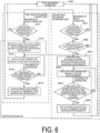
- processing in a defrosting mode M1 will be described with reference to FIG. 6 .
- the processing in the defrosting mode M1 is indicated by being surrounded by a dashed line.
- the processing related to the first heat exchanger 41 on the upwind side is indicated by being surrounded by a dashed-dotted line.
- the processing related to the second heat exchanger 42 on the downwind side is indicated by being surrounded by a dashed-dotted line. Note that the processing related to the second heat exchanger 42 includes the determination of necessity of defrosting for the first heat exchanger 41 (steps S22 and S25).
- step S00 in which at least one of the first heat exchanger 41 or the second heat exchanger 42 is caused to perform a heat-absorbing operation
- the determination of necessity of defrosting for the first heat exchanger 41 based on the detection result of the degree of frost formation by the first temperature detection unit 51 (steps S11 and S22) and the determination of necessity of defrosting for the second heat exchanger 42 based on the detection result of the degree of frost formation by the second temperature detection unit 52 (step S21) are performed in parallel.
- step S00 when it is determined that the first heat exchanger 41 needs to be defrosted from the detection result of the degree of frost formation (Yes in step S11), the defrosting mode M1 is performed. Specifically, the first heat exchanger 41 is selected as the defrosting target by switching the open/close states of the valves 613, 623, and the like (case A1), and the first defrosting processing P1 is started (step S12). Even during the first defrosting processing P1, heating of the vehicle cabin 2 is continued by supplying the high-temperature medium to the vehicle-interior heat exchanger 30. The same applies to the second defrosting processing P2.
- the first defrosting processing P1 is continuously performed until it is determined that the first heat exchanger 41 no longer needs to be defrosted from the detection result of the degree of frost formation (Yes in step S14).
- step S13 When the first defrosting processing P1 is started and the high-temperature medium flows into the first heat exchanger 41 in accordance with the open/close states of the respective ports of the downstream valves 622 and 623 and the upstream valves 613 and 612, the frost adhering to the first heat exchanger 41 is melted by the heat of the high-temperature medium, whereby the defrosting proceeds (step S13).
- step S14 when it is determined that the first heat exchanger 41 no longer needs to be defrosted (Yes in step S14), the first defrosting processing P1 is terminated by switching the open/close states of the valves 613, 623, and the like (step S15).
- step S00 when it is determined that the second heat exchanger 42 needs to be defrosted from the detection result of the degree of frost formation (Yes in step S21), the operation is shifted to the defrosting mode M1 only when it is determined that the first heat exchanger 41 does not need to be defrosted from the degree of frost formation on the first heat exchanger 41 (Yes in step S22).
- the second heat exchanger 42 is selected as the defrosting target by switching the open/close states of the valves 613, 623, and the like (case A2), and the second defrosting processing P2 is started (step S23).
- the defrosting processing P2 for the second heat exchanger 42 is not performed.
- the first defrosting processing P1 is started or has already been performed on the basis of the fact that the first heat exchanger 41 needs to be defrosted (Yes in step S11). That is, in the case A3 where it is determined that both the first heat exchanger 41 and the second heat exchanger 42 need to be defrosted, the first heat exchanger 41 on the upwind side is preferentially selected as the defrosting target (step S12).
- the second defrosting processing P2 is continuously performed until it is determined that the second heat exchanger 42 no longer needs to be defrosted as a result of the progress in the melting of the frost on the second heat exchanger 42 or until it is determined that the first heat exchanger 41 needs to be defrosted as a result of the progress in the frost formation on the first heat exchanger 41 during the second defrosting processing P2 (Yes in step S25).
- the defrosting processing P1 of the first heat exchanger 41 is given preference as in step S22.
- the flow rate of the air flowing through the second heat exchanger 42 is reduced, and thus sufficient heat exchange in the second heat exchanger 42 cannot be expected regardless of the degree of frost formation on the second heat exchanger 42. Therefore, even when the defrosting of the second heat exchanger 42 is not completed yet (the second heat exchanger 42 needs to be defrosted), the open/close states of the valves 613, 623, and the like are switched to terminate the second defrosting processing P2 (step S26), and the processing proceeds to the first defrosting processing P1 (step S12).
- step S21 When it is determined that the second heat exchanger 42 needs to be defrosted (Yes in step S21) at the time when the defrosting of the first heat exchanger 41 is finished (step S15), the defrosting of the first heat exchanger 41 is determined to be no longer necessary (Yes in step S22), and thus the processing is shifted from the first defrosting processing P1 to the second defrosting processing P2. Then, when the second defrosting processing P2 is finished (Yes in step S26), the operation can be returned from the defrosting mode M1 to the heating mode. In the heating mode, since heat is absorbed from outside air by the low-temperature medium flowing through the two heat exchangers 41 and 42 connected in series, the heating operation can be performed with the maximum capacity.
- the necessity of defrosting of each of the first heat exchanger 41 and the second heat exchanger 42 is determined on the basis of the degree of frost formation, and the first heat exchanger 41 and the second heat exchanger 42 are alternatively selected as the defrosting target while the first heat exchanger 41 on the upwind side is given preference over the second heat exchanger 42 on the downwind side.
- the high-temperature medium is supplied to the first heat exchanger 41 before the supply of the high-temperature medium to the second heat exchanger 42 on the downwind side, whereby the amount of heat exchanged by the first heat exchanger 41 can be recovered by melting the frost on the first heat exchanger 41, and the air passages of the first heat exchanger 41 required for recovering the amount of heat exchanged by the second heat exchanger 42 can be maintained.
- the defrosting processing P1 for the first heat exchanger 41 is performed in preference to the defrosting processing P2 for the second heat exchanger 42, the high-temperature medium distributed to the vehicle interior side and the vehicle exterior side are effectively used to recover the amount of heat exchanged by each of the first heat exchanger 41 and the second heat exchanger 42.
- the first defrosting processing P1 is performed on the basis of the determination of the necessity of defrosting the first heat exchanger 41 (steps S11, S22, and S25), whereby the degree of frost formation on the first heat exchanger 41 on the upwind side is maintained to such an extent that the air flow rate is not excessively reduced over the time period during which the defrosting mode M1 is performed.
- a heating capacity above a certain level can be ensured not only in the heating mode but also in the defrosting mode M1. Further, since the high-temperature medium is supplied to an appropriate place at an appropriate time, the first heat exchanger 41 and the second heat exchanger 42 as a whole can quickly finish the defrosting mode M1 and return to the heating mode.
- the connection of the first heat exchanger 41 and the second heat exchanger 42 is switched to series connection or parallel connection by the switching unit 6 to set the respective paths of the high-temperature medium and the low-temperature medium, whereby it is possible to implement various operation modes including the cooling and heating modes in which the first and second heat exchangers 41 and 42 are connected in series and the defrosting mode in which the first and second heat exchangers 41 and 42 are connected in parallel with a simple structure and a simple control at low costs.
- the vehicle air conditioning system 1 may have a freeze cleaning mode in which frost is formed on the vehicle-interior heat exchanger 30 by supplying the low-temperature medium to the vehicle-interior heat exchanger 30, and then the surface of the vehicle-interior heat exchanger 30 is cleaned by melting the frost by supplying the high-temperature medium to the vehicle-interior heat exchanger 30.
- first heat exchanger 41 and the second heat exchanger 42 are connected in parallel with respect to the flow of the heat medium, or that only one of the first and second heat exchangers 41 and 42 is connected to the heat medium circuit for operation.
- the vehicle air conditioning system of the present disclosure may include three or more vehicle-exterior heat exchangers.
- a third heat exchanger may be disposed in series with the first heat exchanger 41 and the second heat exchanger 42 with respect to the flow of air caused by the air blower.
- the degree of frost formation of each of the first to third heat exchangers is detected by the detection unit 5 to determine whether the defrosting of each of the first to third heat exchangers is necessary.
- one of the first to third heat exchangers connected in parallel with respect to the flow of the heat medium that is determined to be in need of the defrosting is selected as a defrosting target.
- the defrosting is preferentially performed on the heat exchanger that is located relatively upwind among the heat exchangers determined to be in need of the defrosting. For example, before the start of the defrosting processing on the third heat exchanger, the necessity of defrosting the third heat exchanger is determined, and the necessity of defrosting the first heat exchanger 41 and the necessity of defrosting the second heat exchanger 42 are also determined. When it is determined that the first heat exchanger 41 or the second heat exchanger 42 needs to be defrosted after the start of the defrosting processing on the third heat exchanger, the defrosting processing on the third heat exchanger is terminated.
- the detection unit 5 for detecting the degree of frost formation on each of the first heat exchanger 41 and the second heat exchanger 42 for example, a camera for capturing images of the external appearances of the first heat exchanger 41 and the second heat exchanger 42 can be used in addition to the temperature detection units 51 and 52.
- image data indicating the degree of frost formation on each of the first heat exchanger 41 and the second heat exchanger 42 can be acquired by one camera.
- the defrosting necessity determination unit 73 can determine the necessity of defrosting each of the first heat exchanger 41 and the second heat exchanger 42 by image processing of the image data.
Landscapes
- Physics & Mathematics (AREA)
- Thermal Sciences (AREA)
- Engineering & Computer Science (AREA)
- Mechanical Engineering (AREA)
- Air-Conditioning For Vehicles (AREA)
Abstract
Description
- The present disclosure relates to an air conditioning system installed in a vehicle, the air conditioning system including a refrigerant circuit and a heat medium circuit, and to an air conditioning method using the air conditioning system.
- In a vehicle such as an electric vehicle in which waste heat of an engine cannot be utilized, there is a need for heat management and waste heat utilization of on-board equipment such as a battery in addition to air conditioning functions required for the vehicle such as cooling, heating, dehumidification, and ventilation in a situation in which a heat source tends to be insufficient. In response to such a need, in addition to an electric heater and a heat pump system, a plurality of systems such as a system including a chiller for cooling a battery and a system for conveying water heated by waste heat of a radiator to a thermal load with a pump have been used.
- A proposed vehicle air conditioning system in which air conditioning and heat management can be integrated is a system including a primary loop in which a refrigerant circulates in accordance with a refrigeration cycle and a secondary loop in which a heat medium (water) that exchanges heat with the refrigerant in the primary loop is conveyed to on-board equipment with a pump (for example, Patent Document 1).
- The vehicle air conditioning system described in
Patent Document 1 includes a low-pressure refrigerant-water heat exchanger that exchanges heat between a low-pressure refrigerant and water, a high-pressure refrigerant-water heat exchanger that exchanges heat between a high-pressure refrigerant and water, a vehicle-interior heat exchanger that exchanges heat between water and vehicle interior air, a vehicle-exterior heat exchanger that exchanges heat between water and outside air, and a plurality of valves for switching a direction of a flow of water. - Such a vehicle system further includes a heater used for a defrosting operation to reliably melt frost attached to the vehicle-exterior heat exchanger during a heating operation. Water heated by the heater is supplied to the vehicle-exterior heat exchanger.
- Patent Document 1:
JP 5971202 B - To enhance heating capacity, the inventors of the present disclosure have studied practical application of a novel vehicle air conditioning system including two or more vehicle-exterior heat exchangers that causes a heat medium to absorb heat from air as a heat source.
- There is no known example of an air conditioning system including a refrigerant circuit and a heat medium circuit including two or more vehicle-exterior heat exchangers. The heating capacity during a defrosting operation is desirably secured by taking appropriate measures against frost formation on the vehicle-exterior heat exchangers.
- In view of the above, an object of the present disclosure relates to an improvement in a vehicle air conditioning system including a refrigerant circuit and a heat medium circuit and including a plurality of vehicle-exterior heat exchangers for exchanging heat between outside air and a heat medium and an improvement in a vehicle air conditioning method.
- The present disclosure is a vehicle air conditioning system including: a refrigerant circuit in which a refrigerant circulates in accordance with a refrigeration cycle; a heat medium circuit including a high-temperature medium circuit in which a heat medium absorbing heat from the refrigerant in the refrigerant circuit circulates and a low-temperature medium circuit in which a heat medium dissipating heat to the refrigerant in the refrigerant circuit circulates; a vehicle-interior heat exchanger configured to exchange heat between the heat medium and air; a vehicle-exterior heat exchanger configured to exchange heat between the heat medium and air and including a first heat exchanger and a second heat exchanger disposed in series with respect to a flow of air generated by an air blower; a switching unit configured to switch a flow of the heat medium; a detection unit configured to detect a degree of frost formation on each of the first heat exchanger and the second heat exchanger; and a control device configured to control operation of the switching unit in accordance with an operation mode of the vehicle air conditioning system.
- The operation mode includes a defrosting mode in which the heat medium in the high-temperature medium circuit is supplied to a defrosting target to be selected as either the first heat exchanger or the second heat exchanger connected in parallel in the heat medium circuit by the operation of the switching unit.
- In selecting the defrosting target by the operation of the switching unit and on the basis of the detection result of a degree of frost formation by the detection unit, the control device selects the first heat exchanger as the defrosting target when it is determined that only the first heat exchanger needs to be defrosted, selects the second heat exchanger as the defrosting target when it is determined that only the second heat exchanger needs to be defrosted, and selects, as the defrosting target, the first heat exchanger located on an upwind side in preference to the second heat exchanger located on a downwind side when it is determined that both the first heat exchanger and the second heat exchanger need to be defrosted.
- The present disclosure is an air conditioning method using a vehicle air conditioning system. The vehicle air conditioning system includes: a refrigerant circuit in which a refrigerant circulates in accordance with a refrigeration cycle; a heat medium circuit including a high-temperature medium circuit in which a heat medium absorbing heat from the refrigerant circulates and a low-temperature medium circuit in which a heat medium dissipating heat to the refrigerant circulates; a vehicle-interior heat exchanger configured to exchange heat between the heat medium and air; a vehicle-exterior heat exchanger configured to exchange heat between the heat medium and air and including a first heat exchanger and a second heat exchanger disposed in series with respect to a flow of air generated by an air blower; and a switching unit configured to switch a flow of the heat medium.
- The air conditioning method of the present disclosure includes: in supplying the heat medium in the high-temperature medium circuit to a defrosting target to be selected as either the first heat exchanger or the second heat exchanger connected in parallel by the operation of the switching unit and on the basis of the detection result of a degree of frost formation on each of the first heat exchanger located on an upwind side and the second heat exchanger located on a downwind side, selecting the first heat exchanger as the defrosting target when it is determined that only the first heat exchanger needs to be defrosted, selecting the second heat exchanger as the defrosting target when it is determined that only the second heat exchanger needs to be defrosted, and selecting, as the defrosting target, the first heat exchanger in preference to the second heat exchanger when it is determined that both the first heat exchanger and the second heat exchanger need to be defrosted.
- In the vehicle air conditioning system and the vehicle air conditioning method according to the present disclosure, the necessity of defrosting of each of the first heat exchanger and the second heat exchanger is determined on the basis of a degree of frost formation, and either the first heat exchanger or the second heat exchanger is selected as the defrosting target while the first heat exchanger on the upwind side is given preference to the second heat exchanger on the downwind side.
- Accordingly, when the flow rate of air flowing through the second heat exchanger decreases due to an increase in air resistance caused by the frost formation on the first heat exchanger on the upwind side, the high-temperature medium is supplied to the first heat exchanger before the supply of the high-temperature medium to the second heat exchanger on the downwind side, thus melting the frost of on the first heat exchanger to recover the amount of heat exchanged by the first heat exchanger and allowing the air passage of the first heat exchanger required for recovering the amount of heat exchanged by the second heat exchanger to be maintained.
- Defrosting processing on the first heat exchanger performed in preference to defrosting processing on the second heat exchanger allows the high-temperature medium to be distributed to a vehicle interior side and a vehicle exterior side to be effectively used to recover the amount of heat exchanged by each of the first heat exchanger and the second heat exchanger and the frost formation on the first heat exchanger on the upwind side to be maintained to such an extent that an air flow rate is not excessively reduced while the defrosting mode is performed.
- Accordingly, the present disclosure allows a heating capacity above a certain level to be maintained not only in a heating mode but also in the defrosting mode and allows the defrosting mode to finish early and the heating mode to be resumed in the entire of the first heat exchanger and the second heat exchanger by supplying the high-temperature medium to the right place at the right time.
-
-
FIG. 1 is a diagram schematically illustrating a vehicle air conditioning system according to an embodiment of the present disclosure.FIG. 1 illustrates an example of respective paths of a low-temperature medium and a high-temperature medium in a cooling mode. -
FIG. 2 is a diagram illustrating an example of respective paths of the low-temperature medium and the high-temperature medium in a heating mode. -
FIG. 3 is a diagram illustrating an example of respective paths of the low-temperature medium and the high-temperature medium during first defrosting processing in a defrosting mode. -
FIG. 4 is a diagram illustrating an example of respective paths of the low-temperature medium and the high-temperature medium during second defrosting processing in the defrosting mode. -
FIG. 5(a) is a block diagram illustrating a part of functions of a control device.FIG. 5(b) is a schematic diagram illustrating a defrosting target selection chart. -
FIG. 6 is a flowchart illustrating a processing flow in the defrosting mode. - An embodiment of the present disclosure will be described below with reference to the accompanying drawings.
- A vehicle
air conditioning system 1 illustrated inFIG. 1 is installed in a vehicle such as an electric vehicle which is not illustrated. The vehicleair conditioning system 1 performs heat management, waste heat recovery, and the like of on-board equipment, which is not illustrated, mounted on the vehicle in addition to air conditioning such as cooling, heating, dehumidifying, and ventilating in avehicle cabin 2 in which a passenger sits. - Note that the vehicle in which the vehicle
air conditioning system 1 is installed is not limited to an electric vehicle, and may be a vehicle equipped with an engine. - The vehicle
air conditioning system 1 includes, as main components, arefrigerant circuit 10 in which a refrigerant circulates in accordance with a refrigeration cycle, aheat medium circuit 20 in which a heat medium that exchanges heat with the refrigerant circulates, a vehicle-interior heat exchanger 30, ablower 33 for the vehicle-interior heat exchanger 30, a plurality of vehicle-exterior heat exchangers 40 (41, 42), ablower 43 for the vehicle-exterior heat exchangers 40 (41, 42), adetection unit 5 for detecting degrees of frost formation on the vehicle-exterior heat exchangers (41, 42), aswitching unit 6 configured to switch a flow of the heat medium in theheat medium circuit 20, and acontrol device 7 configured to control operation of theswitching unit 6 in accordance with an operation mode of the vehicleair conditioning system 1. - The vehicle
air conditioning system 1 has an operation mode such as a cooling mode illustrated inFIG. 1 and a heating mode illustrated inFIG. 2 as well as defrosting modes illustrated inFIGS. 3 and4 . - The vehicle
air conditioning system 1 of the present embodiment performs a defrosting operation on the basis of the degree of frost formation on each of the plurality of vehicle-exterior heat exchangers 40 (41, 42) as will be described later. - The operation mode required for the vehicle
air conditioning system 1 varies depending on a region where a vehicle is used. For example, the vehicleair conditioning system 1 does not need to have a cooling mode. - The
refrigerant circuit 10 includes acompressor 11 for compressing the refrigerant, a heat-absorbingheat exchanger 12, anexpansion valve 13 as a decompression unit for reducing a pressure of the refrigerant that has passed through thecompressor 11 and the heat-absorbingheat exchanger 12, and a heat-dissipatingheat exchanger 14. Therefrigerant circuit 10 generates a heat source for a heat medium (heat-absorbing heat exchanger 12) and a cold source for a heat medium (heat-dissipating heat exchanger 14) by the refrigeration cycle. - The
compressor 11, the heat-absorbingheat exchanger 12, theexpansion valve 13, the heat-dissipatingheat exchanger 14, and refrigerant pipes connecting these elements are installed outside thevehicle cabin 2. - As the refrigerant, a publicly-known appropriate single refrigerant or mixed refrigerant can be used. For example, a hydrofluorocarbon (HFC) refrigerant such as R410A or R32, a hydrofluoroolefin (HFO) refrigerant such as R1234ze or R1234yf, a hydrocarbon (HC) refrigerant such as propane or isobutane can be used, or carbon dioxide can be used as the refrigerant.
- The heat-absorbing
heat exchanger 12 causes the heat medium to absorb heat from the refrigerant through heat exchange between a refrigerant gas discharged from thecompressor 11 and the heat medium. The heat exchange between the refrigerant and the heat medium in the heat-absorbingheat exchanger 12 typically changes the refrigerant into a liquid phase. In this case, the heat-absorbingheat exchanger 12 is equivalent to a condenser. - The heat-dissipating
heat exchanger 14 causes the heat medium to dissipate heat to the refrigerant through heat exchange between the refrigerant that has passed through theexpansion valve 13 and the heat medium. The heat-dissipatingheat exchanger 14 is equivalent to an evaporator. The refrigerant changed into a gas phase in the heat-dissipatingheat exchanger 14 is sucked into thecompressor 11. - The refrigerant circulates in the
refrigerant circuit 10 by a difference between a pressure of the refrigerant in the heat-absorbingheat exchanger 12 and a pressure of the refrigerant in the heat-dissipatingheat exchanger 14. - The
heat medium circuit 20 conveys the heat medium that exchanges heat with the heat source and the cold source made by therefrigerant circuit 10 to the vehicle-interior heat exchanger 30 and the vehicle-exterior heat exchangers (41, 42). The heat medium can be used for air conditioning in thevehicle cabin 2 as well as heat management such as heating and cooling of on-board equipment and waste heat recovery from the on-board equipment. The on-board equipment is, for example, a drive source such as an electric motor, a drive circuit unit, and a power supply device including a battery. - The heat medium is a liquid such as water or brine that circulates in the
heat medium circuit 20 while keeping in a liquid phase. The brine that can be exemplified includes a mixed liquid of water and propylene glycol or a mixed liquid of water and ethylene glycol. - In the
heat medium circuit 20, a heat medium having a relatively high temperature (high-temperature medium) and a heat medium having a relatively low temperature (low-temperature medium) each circulate. In both the cooling mode and the heating mode, the high-temperature medium absorbs heat from the refrigerant in the heat-absorbingheat exchanger 12, and the low-temperature medium dissipates heat to the refrigerant in the heat-dissipatingheat exchanger 14. - In
FIG. 1 , the flow of the low-temperature medium is indicated by solid arrows, and the flow of the high-temperature medium is indicated by dashed-dotted arrows. In theheat medium circuit 20, a path through which the heat medium does not flow is indicated by a dashed line. The same applies toFIG. 2 and subsequent drawings. - The high-temperature medium circulates through a predetermined path in the
heat medium circuit 20 according to an operation mode as indicated by, for example, the dashed-dotted arrows inFIG. 1 . The low-temperature medium circulates through a path in theheat medium circuit 20 according to an operation mode as indicated by, for example, solid arrows inFIG. 1 . - The
heat medium circuit 20 is divided into a low-temperature medium circuit 21 in which the low-temperature medium circulates and a high-temperature medium circuit 22 in which the high-temperature medium circulates by theswitching unit 6 that switches the flow of the heat medium.FIG. 1 illustrates A to D in theheat medium circuit 20. Only the low-temperature medium flows from A to B. Only the high-temperature medium flows from C to D. In the remaining sections of theheat medium circuit 20, either the low-temperature medium or the high-temperature medium flows according to an operation mode. The high-temperature medium is pumped through the high-temperature medium circuit 22 by apump 22P located downstream of the heat-absorbingheat exchanger 12. The low-temperature medium is pumped through the low-temperature medium circuit 21 by apump 21P located downstream of the heat-dissipatingheat exchanger 14. - Even if an outside temperature is so low that it is difficult for the
refrigerant circuit 10 alone to provide a heating capacity, the heating capacity at a low outside temperature can be ensured by using, in combination with therefrigerant circuit 10 theheat medium circuit 20 stably conveying the heat medium that does not change in phase in an operating temperature range with thepumps - In the cooling mode (
FIG. 1 ), the low-temperature medium circulates between the heat-dissipatingheat exchanger 14 and the vehicle-interior heat exchanger 30 through pipes of theheat medium circuit 20 and used for cooling in thevehicle cabin 2. At this time, the high-temperature medium circulates between the heat-absorbingheat exchanger 12 and the vehicle-exterior heat exchangers (41, 42) through pipes of theheat medium circuit 20. - On the other hand, in the heating mode (
FIG. 2 ), the high-temperature medium circulates between the heat-absorbingheat exchanger 12 and the vehicle-interior heat exchanger 30 and used for heating in thevehicle cabin 2. At this time, the low-temperature medium circulates between the heat-dissipatingheat exchanger 14 and the vehicle-exterior heat exchangers (41, 42). - In either operation mode, the
heat medium circuit 20 supplies the high-temperature medium to the vehicle-interior heat exchanger 30 and at least one of the vehicle-exterior heat exchangers (41, 42), and supplies the low-temperature medium to the vehicle-interior heat exchanger 30 and at least one of the vehicle-exterior heat exchangers (41, 42). - The vehicle-
interior heat exchanger 30 is disposed inside a console, a wall, or the like of thevehicle cabin 2, and exchanges heat between the low-temperature medium or the high-temperature medium supplied and air inside thevehicle cabin 2. - The vehicle-
interior heat exchanger 30 constitute a heating, ventilation, and air conditioning (HVAC)unit 3 together with theblower 33, a duct through which air sent by theblower 33 flows, a damper whose degree of opening can be adjusted, and the like. - The vehicle-
interior heat exchanger 30 is composed of a single heat exchanger or a plurality of heat exchangers disposed in series with respect to the flow of air caused by theblower 33. - When the vehicle-
interior heat exchanger 30 is composed of a plurality of heat exchangers, for example, two heat exchangers, opening and closing a valve provided between the heat exchangers can switch the two heat exchangers in a series connection or in a parallel connection for the flow of the heat medium. The flow of the heat medium sequentially flowing through the two heat exchangers connected in series and the flow of the air sequentially flowing through the two heat exchangers preferably form counterflows. - When the two heat exchangers as the vehicle-
interior heat exchanger 30 are connected in parallel, the low-temperature medium can be supplied to one of the two heat exchangers and the high-temperature medium can be supplied to the other. This can perform a dehumidification heating mode of reducing the amount of water vapor in air by causing the low-temperature medium to remove heat from the air and then obtaining conditioned air by causing the high-temperature medium to heat the air to obtain. In the dehumidification heating mode, the low-temperature medium is supplied to the heat exchanger on an upwind side and the high-temperature medium is supplied to the heat exchanger on a downwind side. - Air inside the
vehicle cabin 2 or outside thevehicle cabin 2 sucked by theblower 33 is supplied to the vehicle-interior heat exchanger 30 through the duct, and air cooled by heat exchange with the low-temperature medium or air heated by heat exchange with the high-temperature medium in the vehicle-interior heat exchanger 30 is blown out into thevehicle cabin 2 from an outlet not illustrated. - The
first heat exchanger 41 and thesecond heat exchanger 42 exchange heat between air (outside air) taken in from the outside of thevehicle cabin 2 by the blower 43 (air blower) and the low-temperature medium or the high-temperature medium. By thefirst heat exchanger 41 and thesecond heat exchanger 42, the high-temperature medium that is higher in temperature than the outside air radiates heat to the outside air in the cooling mode illustrated inFIG. 1 , and the low-temperature medium that is lower in temperature than the outside air absorbs heat from the outside air in the heating mode illustrated inFIG. 2 . According to heat absorption by the plurality of vehicle-exterior heat exchangers (41, 42), it is possible to ensure sufficient heating capacity in theair conditioning system 1 mounted on a vehicle such as an electric vehicle in which a heat source tends to be insufficient. - The
first heat exchanger 41 and thesecond heat exchanger 42 are disposed in series with respect to a flow AF given to air by theblower 43. Thefirst heat exchanger 41 is disposed on an upstream side (upwind side) of the flow of air caused by theblower 43. Thesecond heat exchanger 42 is disposed on a downstream side (downwind side) of the flow of air caused by theblower 43. Thus, the air caused to flow by theblower 43 sequentially flows through thefirst heat exchanger 41 and thesecond heat exchanger 42 in this order. - The
first heat exchanger 41 and thesecond heat exchanger 42 are connected via anintermediate valve 60. The connection of thefirst heat exchanger 41 and thesecond heat exchanger 42 can be switched to series connection or parallel connection with respect to the flow of the heat medium in theheat medium circuit 20 by theswitching unit 6 including theintermediate valve 60. - The
first heat exchanger 41 and thesecond heat exchanger 42 as the vehicle-exterior heat exchangers are connected in series in both the cooling mode in which the high-temperature medium is supplied to these heat exchangers as illustrated inFIG. 1 and the heating mode in which the low-temperature medium is supplied to these heat exchangers as illustrated inFIG. 2 . - In a case of the series connection, the
second heat exchanger 42 is located upstream and thefirst heat exchanger 41 is located downstream in theheat medium circuit 20 regardless of an operation mode such as cooling or heating. That is, the heat medium flows through thesecond heat exchanger 42 and thefirst heat exchanger 41 from the downwind side to the upwind side. - Here, the flow of the heat medium sequentially flowing through the
second heat exchanger 42 and thefirst heat exchanger 41 and the flow of the air sequentially flowing through thefirst heat exchanger 41 and thesecond heat exchanger 42 form counterflows. Thus, heat exchange can be efficiently performed while temperature differential between air and the heat medium is sufficiently maintained throughout an entire heat exchange process by thefirst heat exchanger 41 and thesecond heat exchanger 42. - During a heating operation, drain water or moisture in air condenses on the surfaces of the
first heat exchanger 41 and thesecond heat exchanger 42 to form frost. As the frost grows, the resistance of the air passing through gaps (air passages) between members such as fins and tubes included in theheat exchangers - To avoid a decrease in the amount of heat exchanged due to a decrease in the air flow rate, in the present embodiment, the frost is melted by supplying the high-temperature medium in accordance with necessity of defrosting based on the degree of frost formed on the
first heat exchanger 41 and the second heat exchanger 42 (degree of frost formation). - The degree of frost formation on the vehicle-exterior heat exchangers is a degree related to an amount of formed frost that affects the flow rate of the air flowing through the air passages, and specifically, corresponds to a thickness of accumulated frost, a density of frost, or the like.
- The more the amount of attached frost is, the larger the degree of blockage of the air passages by the frost is. As the blockage of the air passages progresses, the heat medium supplied to the heat exchangers becomes unable to absorb heat from air, and is decreased in temperature by being cooled by the frost. That is, the degree of frost formation correlates with the temperature of the heat medium flowing through the heat exchangers. In the present embodiment, as will be described later, a temperature sensor is used to detect the degree of frost formation.
- It is desirable to defrost the heat exchanger that needs to be defrosted while the
vehicle cabin 2 is continuously heated to secure occupant comfort. For this reason, in the defrosting mode, the high-temperature medium is distributed to the vehicle-interior heat exchanger 30 and the vehicle-exterior heat exchangers (41, 42), whereby thevehicle cabin 2 is heated by the supply of the high-temperature medium to the vehicle-interior heat exchanger 30 while the heating capacity is suppressed to a necessary minimum, and the high-temperature medium is supplied to a defrosting target selected as either thefirst heat exchanger 41 or thesecond heat exchanger 42. - In order to secure a heating capacity above a certain level during operation in the defrosting mode, instead of supplying the high-temperature medium to the two
heat exchangers heat exchangers first heat exchanger 41 and thesecond heat exchanger 42 are connected in parallel, and the supply destination of the high-temperature medium is switched between thefirst heat exchanger 41 and thesecond heat exchanger 42 by the operation of theswitching unit 6. That is, when the high-temperature medium is supplied to one of thefirst heat exchanger 41 and thesecond heat exchanger 42, the low-temperature medium is supplied to the other. - The degree of frost formation on the
first heat exchanger 41 located on the upwind side and the degree of frost formation on thesecond heat exchanger 42 located on the downwind side are not necessarily the same. When the frost grows on thefirst heat exchanger 41 on the upwind side, the air resistance increases and the air flow rate decreases due to the frost. Consequently, even if no frost is formed on thesecond heat exchanger 42, the heat exchange capacity of thesecond heat exchanger 42 is also decreases with a decrease in the flow rate of the air flowing through the air passages of thesecond heat exchanger 42. - When the air flow rate decreases due to the frost formation on the
first heat exchanger 41, the heat exchange capacity of thesecond heat exchanger 42 is not recovered even when the high-temperature medium is supplied to thesecond heat exchanger 42 to melt the frost formed on thesecond heat exchanger 42. In order to secure the heat exchange capacity of thesecond heat exchanger 42, the air passages of thefirst heat exchanger 41 need to be maintained by performing the defrosting of thefirst heat exchanger 41 before the defrosting of thesecond heat exchanger 42. - Therefore, in the present embodiment, necessity of defrosting is determined based on the degree of frost formation on each of the
first heat exchanger 41 and thesecond heat exchanger 42, and the defrosting of thefirst heat exchanger 41 on the upwind side is performed in preference to the defrosting of thesecond heat exchanger 42 on the downwind side. When it is determined that the defrosting of thefirst heat exchanger 41 is necessary from the degree of frost formation on thefirst heat exchanger 41, the defrosting of thefirst heat exchanger 41 is immediately performed regardless of the necessity of defrosting of thesecond heat exchanger 42. As will be described later, the defrosting of thesecond heat exchanger 42 is performed only when it is determined that the defrosting of thefirst heat exchanger 41 is not necessary. - The
detection unit 5 includes a firsttemperature detection unit 51 that can detect temperature information indicating a temperature decrease of the heat medium due to the frost formation on thefirst heat exchanger 41, and a secondtemperature detection unit 52 that can detect temperature information indicating a temperature decrease of the heat medium due to the frost formation on thesecond heat exchanger 42. - The first
temperature detection unit 51 of the present embodiment corresponds to a temperature sensor for detecting the temperature of the heat medium that has flowed through, wholly or partway, a path of the heat medium from an inlet to an outlet set for thefirst heat exchanger 41. The firsttemperature detection unit 51 is preferably installed at or near the outlet of the heat medium of thefirst heat exchanger 41. For example, the firsttemperature detection unit 51 is installed in a pipe at the outlet of thefirst heat exchanger 41 so as to be in indirect contact with the heat medium, or in direct contact with the heat medium flowing through the outlet. - Similarly, the second
temperature detection unit 52 corresponds to a temperature sensor for detecting the temperature of the heat medium that has flowed through, wholly or partway, a path of the heat medium from an inlet to an outlet set for thesecond heat exchanger 42 by being in indirect or direct contact with the heat medium. The secondtemperature detection unit 52 is preferably installed at or near the outlet of the heat medium of thesecond heat exchanger 42. - As described above, the temperature of the heat medium that has flowed through the vehicle-exterior heat exchangers (41, 42) varies depending on the degree of blockage of the air passages related to the degree of frost formation.
- Thus, the first
temperature detection unit 51 detects the degree of frost formation on thefirst heat exchanger 41 by detecting the temperature of the heat medium flowing through thefirst heat exchanger 41. Similarly, the secondtemperature detection unit 52 detects the degree of frost formation on thesecond heat exchanger 42 by detecting the temperature of the heat medium flowing through thesecond heat exchanger 42. - Without being limited to the present embodiment, the first
temperature detection unit 51 may include two or more temperature sensors. In that case, for example, one temperature sensor may be installed at each of the inlet and the outlet of thefirst heat exchanger 41, a temperature differential between the temperature of the heat medium at the inlet and the temperature of the heat medium at the outlet may be acquired on the basis of the temperatures detected by the temperature sensors, and the degree of frost formation may be detected on the basis of the temperature differential. The same applies to the secondtemperature detection unit 52. - The
switching unit 6 includes the above-describedintermediate valve 60 located between thefirst heat exchanger 41 and thesecond heat exchanger 42, andupstream valves 611 to 613 anddownstream valves 621 to 623 disposed in theheat medium circuit 20. Theswitching unit 6 switches the respective flows of the high-temperature medium and the low-temperature medium by thesevalves - Each of the
valves control device 7. - Each of the
intermediate valve 60, theupstream valve 611, and theupstream valve 612 described above is a three-way valve, and theupstream valve 613 is a four-way valve. Each of thedownstream valve 621 and thedownstream valve 622 is a three-way valve, and thedownstream valve 623 is a four-way valve. The ports of each valve are selectively opened or closed in accordance with an operation mode, and the heat medium flows through theheat medium circuit 20 along a flow path set inside each valve. - The
upstream valves 611 to 613 are located upstream in theheat medium circuit 20 with respect to the heat-absorbingheat exchanger 12 and the heat-dissipatingheat exchanger 14. Thedownstream valves 621 to 623 are located downstream in theheat medium circuit 20 with respect to the heat-absorbingheat exchanger 12 and the heat-dissipatingheat exchanger 14. The open/close state of theintermediate valve 60, the open/close state of each of theupstream valves 611 to 613, and the open/close state of each of thedownstream valves 621 to 623 are controlled in accordance with an operation mode, whereby the supply destination of the heat medium is switched. - For example, in the cooling mode illustrated in
FIG. 1 , the low-temperature medium (indicated by the solid lines) that has dissipated heat to the refrigerant in the heat-dissipatingheat exchanger 14 and has flowed out from the heat-dissipatingheat exchanger 14 to apipe 801 sequentially flows through apipe 802 and apipe 803 and is supplied to the vehicle-interior heat exchanger 30 in accordance with the open/close state of each port of thedownstream valve 621 and thedownstream valve 622. The low-temperature medium that has flowed out from the vehicle-interior heat exchanger 30 to apipe 804 sequentially flows throughpipes heat exchanger 14 in accordance with the open/close states of theupstream valves - On the other hand, the high-temperature medium (indicated by the dashed-dotted lines) that has absorbed heat from the refrigerant in the heat-absorbing
heat exchanger 12 and has flowed out from the heat-absorbingheat exchanger 12 to apipe 821, sequentially flows through thedownstream valve 622, apipe 822, thedownstream valve 623, and apipe 823, and is supplied to thesecond heat exchanger 42 and thefirst heat exchanger 41. Waste heat of the vehicleair conditioning system 1 can be discharged to outside air through heat exchange between the high-temperature medium and the outside air by thesecond heat exchanger 42 and thefirst heat exchanger 41. The high-temperature medium that has flowed out from thefirst heat exchanger 41 to apipe 824 sequentially flows throughpipes heat exchanger 12 in accordance with the open/close states of theupstream valves - In the heating mode illustrated in
FIG. 2 , the high-temperature medium that has absorbed heat from the refrigerant in the heat-absorbingheat exchanger 12 and has flowed out from the heat-absorbingheat exchanger 12 to thepipe 821 flows through thepipe 803 and is supplied to the vehicle-interior heat exchanger 30 in accordance with the open/close states of the ports of thedownstream valve 622 and thedownstream valve 621. The high-temperature medium that has flowed out from the vehicle-interior heat exchanger 30 to thepipe 804 flows through thepipe 826 and returns to the heat-absorbingheat exchanger 12 in accordance with the open/close states of theupstream valves - On the other hand, the low-temperature medium that has dissipated heat to the refrigerant in the heat-dissipating
heat exchanger 14 and has flowed out from the heat-dissipatingheat exchanger 14 to thepipe 801, sequentially flows through thedownstream valve 621, thepipe 807, and thepipe 823, and is supplied to thesecond heat exchanger 42 and thefirst heat exchanger 41. The heat medium can absorb heat from outside air through heat exchange between the low-temperature medium and the outside air in thesecond heat exchanger 42 and thefirst heat exchanger 41. The heat medium that has flowed out from thefirst heat exchanger 41 to thepipe 824 flows through thepipe 806 and returns to the heat-dissipatingheat exchanger 14 in accordance with the open/close states of theupstream valves -
FIG. 3 illustrates a first defrosting processing P1 in the defrosting mode. The defrosting target during the first defrosting processing P1 is thefirst heat exchanger 41.FIG. 4 illustrates a second defrosting processing P2 in the defrosting mode. The defrosting target during the second defrosting processing P2 is thesecond heat exchanger 42. - In the defrosting mode, the
first heat exchanger 41 and thesecond heat exchanger 42 are connected in parallel with respect to the flow of the heat medium, and the high-temperature medium is supplied to the vehicle-interior heat exchanger 30 and the vehicle-exterior heat exchangers upstream valves downstream valves - In addition, one of the
first heat exchanger 41 and thesecond heat exchanger 42 is selected as the defrosting target by switching the open/close states of the respective ports of theupstream valve 613 and thedownstream valve 623. - As illustrated in
FIG. 3 , during the first defrosting processing P1, the high-temperature medium that has flowed out from the heat-absorbingheat exchanger 12 is supplied to thefirst heat exchanger 41 as the defrosting target via thedownstream valve 622 and thedownstream valve 623. At this time, the low-temperature medium that has flowed out from the heat-dissipatingheat exchanger 14 is supplied to thesecond heat exchanger 42 via thedownstream valve 621 and thedownstream valve 623. During the first defrosting processing P1, since heat cannot be absorbed from outside air by thefirst heat exchanger 41 to which the high-temperature medium is supplied, heat is absorbed from outside air to the low-temperature medium only by thesecond heat exchanger 42. - As illustrated in
FIG. 4 , during the second defrosting processing P2, the high-temperature medium that has flowed out from the heat-absorbingheat exchanger 12 is supplied to thesecond heat exchanger 42 via thedownstream valve 622 and thedownstream valve 623. At this time, the low-temperature medium that has flowed out from the heat-dissipatingheat exchanger 14 is supplied to thefirst heat exchanger 41 via thedownstream valve 621 and thedownstream valve 623. During the second defrosting processing P2, heat is absorbed from outside air to the low-temperature medium only by thefirst heat exchanger 41. - The number and the arrangement of the valves constituting the
switching unit 6 according to the present embodiment, and the setting of the respective paths of the low-temperature medium and the high-temperature medium in each operation mode depending on the number and the arrangement, and the like are only examples. To achieve the respective flows of the low-temperature medium and the high-temperature medium in each operation mode provided in the vehicleair conditioning system 1, a switching unit having an appropriate configuration can be employed. - The
control device 7 controls at least the operation of theswitching unit 6 in theair conditioning system 1.FIG. 5(a) illustrates amode selection unit 71 for selecting an operation mode and a switchingoperation control unit 72 for controlling the operation of theswitching unit 6, and a defrostingnecessity determination unit 73 and a defrostingtarget selection unit 74 for the defrosting operation, as some control modules included in thecontrol device 7. Each control module is included in a computer program executed by a computer or an embedded program executed by an electronic circuit. - The
mode selection unit 71 selects one operation mode from among a plurality of operation modes such as a cooling mode, a heating mode, and a defrosting mode in response to a user operation or under control by thecontrol device 7. - The switching
operation control unit 72 switches the flow of each of the high-temperature medium and the low-temperature medium in theheat medium circuit 20 by sending a control command to thevalves switching unit 6 in accordance with the operation mode selected by themode selection unit 71. - The defrosting
necessity determination unit 73 determines the necessity of defrosting thefirst heat exchanger 41 on the basis of the detection result (temperature) by the firsttemperature detection unit 51. Before the start of the first defrosting processing P1 for defrosting thefirst heat exchanger 41, for example, the defrosting is determined to be necessary if the temperature detected by the firsttemperature detection unit 51 is lower than a predetermined first start threshold value Ts1, and the defrosting is determined to be unnecessary if the detected temperature is higher than the first start threshold value Ts1. - The same applies to the
second heat exchanger 42. Before the start of the second defrosting processing P2 for defrosting thesecond heat exchanger 42, for example, the defrostingnecessity determination unit 73 determines that the defrosting is necessary if the temperature detected by the secondtemperature detection unit 52 is lower than a predetermined second start threshold value Ts2, and determines that the defrosting is unnecessary if the detected temperature is higher than the second start threshold value Ts2. - The first start threshold value Ts1 can be set to an appropriate value in consideration of the degree of blockage of the air passages of the
first heat exchanger 41. Similarly, the second start threshold value Ts2 can be set to an appropriate value in consideration of the degree of blockage of the air passages of thesecond heat exchanger 42. The first start threshold value Ts1 and the second start threshold value Ts2 may be identical to or different from each other. - After the start of the first defrosting processing P1, for example, if the temperature detected by the first
temperature detection unit 51 is lower than a predetermined first finish threshold value Tf1 that is higher than the first start threshold value Ts1, the defrostingnecessity determination unit 73 determines that the defrosting is still necessary and continues the first defrosting processing P1. If the detected temperature is higher than the first finish threshold value Tf1, the defrosting is determined to be no longer necessary, and the first defrosting processing P1 is terminated. - The same applies to the
second heat exchanger 42. After the start of the second defrosting processing P2, for example, if the temperature detected by the secondtemperature detection unit 52 is lower than a predetermined second finish threshold value Tf2 that is higher than the second start threshold value Ts2, the defrostingnecessity determination unit 73 determines that the defrosting is still necessary and continues the second defrosting processing P2. If the detected temperature is higher than the second finish threshold value Tf2, the defrosting is determined to be no longer necessary, and the second defrosting processing P2 is terminated. - The defrosting
target selection unit 74 selects the defrosting target on the basis of the necessity of defrosting determined by the defrostingnecessity determination unit 73 while giving preference to thefirst heat exchanger 41 on the upwind side. -
FIG. 5(b) illustrates a logic used for the selection of the defrosting target by the defrostingtarget selection unit 74. There may be four cases A1 to A4 illustrated inFIG. 5(b) regarding the necessity of defrosting based on the detection result by the firsttemperature detection unit 51 and the detection result by the secondtemperature detection unit 52. - When it is determined that only the
first heat exchanger 41 needs to be defrosted, thefirst heat exchanger 41 is selected as the defrosting target. - When it is determined that only the
second heat exchanger 42 needs to be defrosted, thesecond heat exchanger 42 is selected as the defrosting target. - When it is determined that both the
first heat exchanger 41 and thesecond heat exchanger 42 need to be defrosted, thefirst heat exchanger 41 located on the upwind side is selected as the defrosting target in preference to thesecond heat exchanger 42 located on the downwind side. - When it is determined that neither the
first heat exchanger 41 nor thesecond heat exchanger 42 needs to be defrosted, neither thefirst heat exchanger 41 nor thesecond heat exchanger 42 is selected as the defrosting target. (There is no defrosting target) - As an example of a processing procedure, processing in a defrosting mode M1 will be described with reference to
FIG. 6 . The processing in the defrosting mode M1 is indicated by being surrounded by a dashed line. - On the left side in
FIG. 6 , the processing related to thefirst heat exchanger 41 on the upwind side is indicated by being surrounded by a dashed-dotted line. On the right side inFIG. 6 , the processing related to thesecond heat exchanger 42 on the downwind side is indicated by being surrounded by a dashed-dotted line. Note that the processing related to thesecond heat exchanger 42 includes the determination of necessity of defrosting for the first heat exchanger 41 (steps S22 and S25). - During a heat-absorbing operation (step S00) in which at least one of the
first heat exchanger 41 or thesecond heat exchanger 42 is caused to perform a heat-absorbing operation, the determination of necessity of defrosting for thefirst heat exchanger 41 based on the detection result of the degree of frost formation by the first temperature detection unit 51 (steps S11 and S22) and the determination of necessity of defrosting for thesecond heat exchanger 42 based on the detection result of the degree of frost formation by the second temperature detection unit 52 (step S21) are performed in parallel. - When it is determined that neither the
first heat exchanger 41 nor thesecond heat exchanger 42 needs to be defrosted (No in step S11 and No in step S21), there is no defrosting target, and the heat-absorbing operation (S00) is continued. This corresponds to the case A4 illustrated inFIG. 5(b) . - During the heat-absorbing operation (step S00), when it is determined that the
first heat exchanger 41 needs to be defrosted from the detection result of the degree of frost formation (Yes in step S11), the defrosting mode M1 is performed. Specifically, thefirst heat exchanger 41 is selected as the defrosting target by switching the open/close states of thevalves vehicle cabin 2 is continued by supplying the high-temperature medium to the vehicle-interior heat exchanger 30. The same applies to the second defrosting processing P2. - The first defrosting processing P1 is continuously performed until it is determined that the
first heat exchanger 41 no longer needs to be defrosted from the detection result of the degree of frost formation (Yes in step S14). - When the first defrosting processing P1 is started and the high-temperature medium flows into the
first heat exchanger 41 in accordance with the open/close states of the respective ports of thedownstream valves upstream valves first heat exchanger 41 is melted by the heat of the high-temperature medium, whereby the defrosting proceeds (step S13). As a result, when it is determined that thefirst heat exchanger 41 no longer needs to be defrosted (Yes in step S14), the first defrosting processing P1 is terminated by switching the open/close states of thevalves - On the other hand, during the heat-absorbing operation (step S00), when it is determined that the
second heat exchanger 42 needs to be defrosted from the detection result of the degree of frost formation (Yes in step S21), the operation is shifted to the defrosting mode M1 only when it is determined that thefirst heat exchanger 41 does not need to be defrosted from the degree of frost formation on the first heat exchanger 41 (Yes in step S22). Specifically, thesecond heat exchanger 42 is selected as the defrosting target by switching the open/close states of thevalves second heat exchanger 42 needs to be defrosted, if it is determined that thefirst heat exchanger 41 needs to be defrosted (No in step S22), the defrosting processing P2 for thesecond heat exchanger 42 is not performed. At this time, the first defrosting processing P1 is started or has already been performed on the basis of the fact that thefirst heat exchanger 41 needs to be defrosted (Yes in step S11). That is, in the case A3 where it is determined that both thefirst heat exchanger 41 and thesecond heat exchanger 42 need to be defrosted, thefirst heat exchanger 41 on the upwind side is preferentially selected as the defrosting target (step S12). - The second defrosting processing P2 is continuously performed until it is determined that the
second heat exchanger 42 no longer needs to be defrosted as a result of the progress in the melting of the frost on thesecond heat exchanger 42 or until it is determined that thefirst heat exchanger 41 needs to be defrosted as a result of the progress in the frost formation on thefirst heat exchanger 41 during the second defrosting processing P2 (Yes in step S25). When it is determined in step S25 that thefirst heat exchanger 41 needs to be defrosted, that is, both thefirst heat exchanger 41 and thesecond heat exchanger 42 need to be defrosted (case A3), the defrosting processing P1 of thefirst heat exchanger 41 is given preference as in step S22. - During the second defrosting processing P2, heat is absorbed from outside air to the low-temperature medium only by the
first heat exchanger 41 on the upwind side. As a result, the amount of heat exchanged between the outside air and the low-temperature medium decreases as compared with the case where heat is absorbed from the outside air to the low-temperature medium by the twoheat exchangers first heat exchanger 41 decreases and the frost formation on thefirst heat exchanger 41 is likely to progress. When it is determined that thefirst heat exchanger 41 needs to be defrosted, the flow rate of the air flowing through thesecond heat exchanger 42 is reduced, and thus sufficient heat exchange in thesecond heat exchanger 42 cannot be expected regardless of the degree of frost formation on thesecond heat exchanger 42. Therefore, even when the defrosting of thesecond heat exchanger 42 is not completed yet (thesecond heat exchanger 42 needs to be defrosted), the open/close states of thevalves - When it is determined that the
second heat exchanger 42 needs to be defrosted (Yes in step S21) at the time when the defrosting of thefirst heat exchanger 41 is finished (step S15), the defrosting of thefirst heat exchanger 41 is determined to be no longer necessary (Yes in step S22), and thus the processing is shifted from the first defrosting processing P1 to the second defrosting processing P2. Then, when the second defrosting processing P2 is finished (Yes in step S26), the operation can be returned from the defrosting mode M1 to the heating mode. In the heating mode, since heat is absorbed from outside air by the low-temperature medium flowing through the twoheat exchangers - According to the vehicle
air conditioning system 1 and the vehicle air conditioning method using the vehicleair conditioning system 1 of the present embodiment, the necessity of defrosting of each of thefirst heat exchanger 41 and thesecond heat exchanger 42 is determined on the basis of the degree of frost formation, and thefirst heat exchanger 41 and thesecond heat exchanger 42 are alternatively selected as the defrosting target while thefirst heat exchanger 41 on the upwind side is given preference over thesecond heat exchanger 42 on the downwind side. - Accordingly, when the flow rate of the air flowing through the
second heat exchanger 42 decreases due to an increase in air resistance caused by the frost formation on thefirst heat exchanger 41 on the upwind side, the high-temperature medium is supplied to thefirst heat exchanger 41 before the supply of the high-temperature medium to thesecond heat exchanger 42 on the downwind side, whereby the amount of heat exchanged by thefirst heat exchanger 41 can be recovered by melting the frost on thefirst heat exchanger 41, and the air passages of thefirst heat exchanger 41 required for recovering the amount of heat exchanged by thesecond heat exchanger 42 can be maintained. - Since the defrosting processing P1 for the
first heat exchanger 41 is performed in preference to the defrosting processing P2 for thesecond heat exchanger 42, the high-temperature medium distributed to the vehicle interior side and the vehicle exterior side are effectively used to recover the amount of heat exchanged by each of thefirst heat exchanger 41 and thesecond heat exchanger 42. Then, the first defrosting processing P1 is performed on the basis of the determination of the necessity of defrosting the first heat exchanger 41 (steps S11, S22, and S25), whereby the degree of frost formation on thefirst heat exchanger 41 on the upwind side is maintained to such an extent that the air flow rate is not excessively reduced over the time period during which the defrosting mode M1 is performed. - Therefore, according to the present embodiment, a heating capacity above a certain level can be ensured not only in the heating mode but also in the defrosting mode M1. Further, since the high-temperature medium is supplied to an appropriate place at an appropriate time, the
first heat exchanger 41 and thesecond heat exchanger 42 as a whole can quickly finish the defrosting mode M1 and return to the heating mode. - Further, according to the vehicle
air conditioning system 1 and the vehicle air conditioning method using the vehicleair conditioning system 1 of the present disclosure, the connection of thefirst heat exchanger 41 and thesecond heat exchanger 42 is switched to series connection or parallel connection by theswitching unit 6 to set the respective paths of the high-temperature medium and the low-temperature medium, whereby it is possible to implement various operation modes including the cooling and heating modes in which the first andsecond heat exchangers second heat exchangers - Besides the above-described embodiment, configurations explained in the above-described embodiment can be selected or omitted as desired or can be changed to other configurations as necessary.
- Appropriately setting the respective paths of the high-temperature medium and the low-temperature medium in accordance with the open/close state of each valve as the
switching unit 6 can implement not only the above-described embodiment but also various kinds of operation modes. For example, the vehicleair conditioning system 1 may have a freeze cleaning mode in which frost is formed on the vehicle-interior heat exchanger 30 by supplying the low-temperature medium to the vehicle-interior heat exchanger 30, and then the surface of the vehicle-interior heat exchanger 30 is cleaned by melting the frost by supplying the high-temperature medium to the vehicle-interior heat exchanger 30. - In the cooling mode or the heating mode, it is not excluded that the
first heat exchanger 41 and thesecond heat exchanger 42 are connected in parallel with respect to the flow of the heat medium, or that only one of the first andsecond heat exchangers - The vehicle air conditioning system of the present disclosure may include three or more vehicle-exterior heat exchangers. For example, in addition to the
first heat exchanger 41 and thesecond heat exchanger 42 described above, a third heat exchanger may be disposed in series with thefirst heat exchanger 41 and thesecond heat exchanger 42 with respect to the flow of air caused by the air blower. In that case, the degree of frost formation of each of the first to third heat exchangers is detected by thedetection unit 5 to determine whether the defrosting of each of the first to third heat exchangers is necessary. Similar to the above-described embodiment, one of the first to third heat exchangers connected in parallel with respect to the flow of the heat medium that is determined to be in need of the defrosting is selected as a defrosting target. When two or more of the first to third heat exchangers are determined to be in need of the defrosting, the defrosting is preferentially performed on the heat exchanger that is located relatively upwind among the heat exchangers determined to be in need of the defrosting. For example, before the start of the defrosting processing on the third heat exchanger, the necessity of defrosting the third heat exchanger is determined, and the necessity of defrosting thefirst heat exchanger 41 and the necessity of defrosting thesecond heat exchanger 42 are also determined. When it is determined that thefirst heat exchanger 41 or thesecond heat exchanger 42 needs to be defrosted after the start of the defrosting processing on the third heat exchanger, the defrosting processing on the third heat exchanger is terminated. - As the
detection unit 5 for detecting the degree of frost formation on each of thefirst heat exchanger 41 and thesecond heat exchanger 42, for example, a camera for capturing images of the external appearances of thefirst heat exchanger 41 and thesecond heat exchanger 42 can be used in addition to thetemperature detection units first heat exchanger 41 and thesecond heat exchanger 42 can be acquired by one camera. The defrostingnecessity determination unit 73 can determine the necessity of defrosting each of thefirst heat exchanger 41 and thesecond heat exchanger 42 by image processing of the image data. - The vehicle air conditioning system and the vehicle air conditioning method described above are understood as follows.
- [1] A vehicle
air conditioning system 1 includes: arefrigerant circuit 10 in which a refrigerant circulates in accordance with a refrigeration cycle; aheat medium circuit 20 including a high-temperature medium circuit 22 in which a heat medium absorbing heat from the refrigerant in therefrigerant circuit 10 circulates and a low-temperature medium circuit 21 in which the heat medium dissipating heat to the refrigerant in therefrigerant circuit 10 circulates; a vehicle-interior heat exchanger 30 configured to exchange heat between the heat medium and air; a vehicle-exterior heat exchanger configured to exchange heat between the heat medium and air and including afirst heat exchanger 41 and asecond heat exchanger 42 disposed in series with respect to a flow of air generated by ablower 43; aswitching unit 6 configured to switch a flow of the heat medium; adetection unit 5 configured to detect a degree of frost formation on each of thefirst heat exchanger 41 and thesecond heat exchanger 42; and acontrol device 7 configured to control operation of theswitching unit 6 in accordance with an operation mode of the vehicleair conditioning system 1.
The operation mode includes a defrosting mode M1 in which the heat medium in the high-temperature medium circuit 22 is supplied to a defrosting target to be selected as either thefirst heat exchanger 41 or thesecond heat exchanger 42 connected in parallel in theheat medium circuit 20 by the operation of theswitching unit 6.
In selecting the defrosting target by the operation of theswitching unit 6 and on the basis of the detection result of a degree of frost formation by thedetection unit 5, thecontrol device 7 selects thefirst heat exchanger 41 as the defrosting target when it is determined that only thefirst heat exchanger 41 needs to be defrosted, selects thesecond heat exchanger 42 as the defrosting target when it is determined that only thesecond heat exchanger 42 needs to be defrosted, and selects, as the defrosting target, thefirst heat exchanger 41 located on an upwind side in preference to thesecond heat exchanger 42 located on a downwind side when it is determined that both thefirst heat exchanger 41 and thesecond heat exchanger 42 need to be defrosted. - [2] The
control device 7 includes a defrostingnecessity determination unit 73 that determines the necessity of defrosting each of thefirst heat exchanger 41 and thesecond heat exchanger 42 on the basis of the detection result, and a defrostingtarget selection unit 74 that selects the defrosting target on the basis of the necessity of defrosting determined by the defrostingnecessity determination unit 73 while giving preference to thefirst heat exchanger 41 on the upwind side. The defrostingtarget selection unit 74 starts a first defrosting processing P1 for supplying the heat medium in the high-temperature medium circuit 22 to thefirst heat exchanger 41 as the defrosting target when it is determined that thefirst heat exchanger 41 needs to be defrosted, terminates the first defrosting processing P1 after start of the first defrosting processing and when it is determined that thefirst heat exchanger 41 no longer needs to be defrosted, starts a second defrosting processing P2 for supplying the heat medium of the high-temperature medium circuit 22 to thesecond heat exchanger 42 as the defrosting target when it is determined that thesecond heat exchanger 42 needs to be defrosted and when it is determined that thefirst heat exchanger 41 does not need to be defrosted, and terminates the second defrosting processing P2 after start of the second defrosting processing P2 and when it is determined that thefirst heat exchanger 41 needs to be defrosted or when it is determined that thesecond heat exchanger 42 no longer needs to be defrosted. - [3] The vehicle
air conditioning system 1 includes, as thedetection unit 5, a firsttemperature detection unit 51 configured to detect temperature information indicating a temperature decrease of the heat medium due to a frost formation on thefirst heat exchanger 41 and a secondtemperature detection unit 52 configured to detect temperature information indicating a temperature decrease of the heat medium due to a frost formation on thesecond heat exchanger 42. - [4] The operation mode includes a heating mode in which the heat medium in the low-
temperature medium circuit 21 is supplied to thefirst heat exchanger 41 and thesecond heat exchanger 42 connected in series by the operation of theswitching unit 6. In the heating mode, the heat medium flows through thesecond heat exchanger 42 and thefirst heat exchanger 41 from the downwind side to the upwind side. - [5] The
switching unit 6 includes a three-way valve located between thefirst heat exchanger 41 and thesecond heat exchanger 42. - [6] In an air conditioning method using a vehicle
air conditioning system 1, the vehicleair conditioning system 1 includes: arefrigerant circuit 10 in which a refrigerant circulates in accordance with a refrigeration cycle; aheat medium circuit 20 including a high-temperature medium circuit 22 in which a heat medium absorbing heat from the refrigerant circulates and a low-temperature medium circuit in which the heat medium dissipating heat to the refrigerant circulates; a vehicle-interior heat exchanger 30 configured to exchange heat between the heat medium and air; a vehicle-exterior heat exchanger configured to exchange heat between the heat medium and air and including afirst heat exchanger 41 and asecond heat exchanger 42 disposed in series with respect to a flow of air generated by ablower 43; and aswitching unit 6 configured to switch a flow of the heat medium. The air conditioning method of the present disclosure includes: in supplying the heat medium in the high-temperature medium circuit 22 to a defrosting target to be selected as either thefirst heat exchanger 41 or thesecond heat exchanger 42 connected in parallel by an operation of theswitching unit 6 and on the basis of a detection result of a degree of frost formation on each of thefirst heat exchanger 41 located on an upwind side and thesecond heat exchanger 42 located on a downwind side, selecting thefirst heat exchanger 41 as the defrosting target when it is determined that only thefirst heat exchanger 41 needs to be defrosted; selecting thesecond heat exchanger 42 as the defrosting target when it is determined that only thesecond heat exchanger 42 needs to be defrosted; and selecting, as the defrosting target, thefirst heat exchanger 41 in preference to thesecond heat exchanger 42 when it is determined that both thefirst heat exchanger 41 and thesecond heat exchanger 42 need to be defrosted. - [7] The air conditioning method of the present disclosure includes: in defrosting each of the
first heat exchanger 41 and thesecond heat exchanger 42 while selecting the defrosting target on the basis of the degree of frost formation determined by the detection result while giving preference to thefirst heat exchanger 41, starting a first defrosting processing P1 for supplying the heat medium in the high-temperature medium circuit 22 to thefirst heat exchanger 41 as the defrosting target when it is determined that thefirst heat exchanger 41 needs to be defrosted; terminating the first defrosting processing P1 after start of the first defrosting processing P1 and when it is determined that thefirst heat exchanger 41 no longer needs to be defrosted; starting a second defrosting processing P2 for supplying the heat medium of the high-temperature medium circuit 22 to thesecond heat exchanger 42 as the defrosting target when it is determined that thesecond heat exchanger 42 needs to be defrosted and when it is determined that thefirst heat exchanger 41 does not need to be defrosted; and terminating the second defrosting processing P2 after start of the second defrosting processing P2 and when it is determined that thefirst heat exchanger 41 needs to be defrosted or when it is determined that thesecond heat exchanger 42 no longer needs to be defrosted. -
- 1 Vehicle air conditioning system
- 2 Vehicle cabin
- 3 HVAC unit
- 5 Detection unit
- 6 Switching unit
- 7 Control device
- 10 Refrigerant circuit
- 11 Compressor
- 12 Heat-absorbing heat exchanger
- 13 Expansion valve
- 14 Heat-dissipating heat exchanger
- 20 Heat Medium Circuit
- 21 Low-temperature medium circuit
- 21P Pump
- 22 High-temperature medium circuit
- 22P Pump
- 30 Vehicle-interior heat exchanger
- 33 Blower
- 40 Vehicle-exterior heat exchanger
- 41 First heat exchanger
- 42 Second heat exchanger
- 43 Blower (air blower)
- 51 First temperature detection unit
- 52 Second temperature detection unit
- 60 Intermediate valve
- 71 Mode selection unit
- 72 Switching operation control unit
- 73 Defrosting necessity determination unit
- 74 Defrosting target selection unit
- 611 to 613 Upstream valve
- 621 to 623 Downstream valve
- 801 to 811 Pipe
- 821 to 826 Pipe
- M1 Defrosting mode
- P1 First defrosting processing
- P2 Second defrosting processing
- 500, S11 to S15, S21 to S26 Step
- Ts1 First start threshold value
- Tf1 First finish threshold value
- Ts2 Second start threshold value
- Tf2 Second finish threshold value
Claims (7)
- A vehicle air conditioning system, comprising:a refrigerant circuit in which a refrigerant circulates in accordance with a refrigeration cycle;a heat medium circuit including a high-temperature medium circuit in which a heat medium absorbing heat from the refrigerant in the refrigerant circuit circulates and a low-temperature medium circuit in which a heat medium dissipating heat to the refrigerant in the refrigerant circuit circulates;a vehicle-interior heat exchanger configured to exchange heat between the heat medium and air;a vehicle-exterior heat exchanger configured to exchange heat between the heat medium and air and including a first heat exchanger and a second heat exchanger disposed in series with respect to a flow of air generated by an air blower;a switching unit configured to switch a flow of the heat medium;a detection unit configured to detect a degree of frost formation on each of the first heat exchanger and the second heat exchanger; anda control device configured to control operation of the switching unit in accordance with an operation mode of the vehicle air conditioning system, whereinthe operation mode includes a defrosting mode in which the heat medium in the high-temperature medium circuit is supplied to a defrosting target to be selected as either the first heat exchanger or the second heat exchanger connected in parallel in the heat medium circuit by the operation of the switching unit, andin selecting the defrosting target by the operation of the switching unit and on the basis of a detection result of the degree of frost formation by the detection unit, the control deviceselects the first heat exchanger as the defrosting target when it is determined that only the first heat exchanger needs to be defrosted,selects the second heat exchanger as the defrosting target when it is determined that only the second heat exchanger needs to be defrosted, andselects, as the defrosting target, the first heat exchanger located on an upwind side in preference to the second heat exchanger located on a downwind side when it is determined that both the first heat exchanger and the second heat exchanger need to be defrosted.
- The vehicle air conditioning system according to claim 1, whereinthe control device includesa defrosting necessity determination unit configured to determine necessity of defrosting each of the first heat exchanger and the second heat exchanger on the basis of the detection result anda defrosting target selection unit configured to select the defrosting target on the basis of the necessity of defrosting determined by the defrosting necessity determination unit while giving preference to the first heat exchanger on the upwind side, andthe defrosting target selection unitstarts a first defrosting processing for supplying the heat medium in the high-temperature medium circuit to the first heat exchanger as the defrosting target when it is determined that the first heat exchanger needs to be defrosted,terminates the first defrosting processing after start of the first defrosting processing and when it is determined that the first heat exchanger no longer needs to be defrosted,starts a second defrosting processing for supplying the heat medium in the high-temperature medium circuit to the second heat exchanger as the defrosting target when it is determined that the second heat exchanger needs to be defrosted and when it is determined that the first heat exchanger does not need to be defrosted, andterminates the second defrosting processing after start of the second defrosting processing and when it is determined that the first heat exchanger needs to be defrosted or when it is determined that the second heat exchanger no longer needs to be defrosted.
- The vehicle air conditioning system according to claim 1 or 2, whereinthe detection unit includesa first temperature detection unit configured to detect temperature information indicating a temperature decrease of the heat medium due to a frost formation on the first heat exchanger anda second temperature detection unit configured to detect temperature information indicating a temperature decrease of the heat medium due to a frost formation on the second heat exchanger.
- The vehicle air conditioning system according to any one of claims 1 to 3, whereinthe operation mode includes a heating mode in which the heat medium in the low-temperature medium circuit is supplied to the first heat exchanger and the second heat exchanger connected in series by the operation of the switching unit, andin the heating mode, the heat medium flows through the second heat exchanger and the first heat exchanger from the downwind side to the upwind side.
- The vehicle air conditioning system according to any one of claims 1 to 4, wherein the switching unit includes a three-way valve located between the first heat exchanger and the second heat exchanger.
- A vehicle air conditioning method using a vehicle air conditioning system,
the vehicle air conditioning system comprising:a refrigerant circuit in which a refrigerant circulates in accordance with a refrigeration cycle;a heat medium circuit including a high-temperature medium circuit in which a heat medium absorbing heat from the refrigerant in the refrigerant circuit circulates and a low-temperature medium circuit in which the heat medium dissipating heat to the refrigerant in the refrigerant circuit circulates;a vehicle-interior heat exchanger configured to exchange heat between the heat medium and air;a vehicle-exterior heat exchanger configured to exchange heat between the heat medium and air and including a first heat exchanger and a second heat exchanger disposed in series with respect to a flow of air generated by an air blower; anda switching unit configured to switch a flow of the heat medium,the vehicle air conditioning method comprising:in supplying the heat medium in the high-temperature medium circuit to a defrosting target to be selected as either the first heat exchanger or the second heat exchanger connected in parallel by operation of the switching unit andon the basis of a detection result of a degree of frost formation on each of the first heat exchanger located on an upwind side and the second heat exchanger located on a downwind side,selecting the first heat exchanger as the defrosting target when it is determined that only the first heat exchanger needs to be defrosted;selecting the second heat exchanger as the defrosting target when it is determined that only the second heat exchanger needs to be defrosted; andselecting, as the defrosting target, the first heat exchanger in preference to the second heat exchanger when it is determined that both the first heat exchanger and the second heat exchanger need to be defrosted. - The vehicle air conditioning method according to claim 6, comprising:in defrosting each of the first heat exchanger and the second heat exchanger while selecting the defrosting target on the basis of the degree of frost formation determined by the detection result while giving preference to the first heat exchanger,starting a first defrosting processing for supplying the heat medium in the high-temperature medium circuit to the first heat exchanger as the defrosting target if it is determined that the first heat exchanger needs to be defrosted;terminating the first defrosting processing after start of the first defrosting processing and if it is determined that the first heat exchanger no longer needs to be defrosted;starting a second defrosting processing for supplying the heat medium in the high-temperature medium circuit to the second heat exchanger as the defrosting target when it is determined that the second heat exchanger needs to be defrosted and when it is determined that the first heat exchanger does not need to be defrosted; andterminating the second defrosting processing after start of the second defrosting processing and when it is determined that the first heat exchanger needs to be defrosted or when it is determined that the second heat exchanger no longer needs to be defrosted.
Applications Claiming Priority (2)
| Application Number | Priority Date | Filing Date | Title |
|---|---|---|---|
| JP2021075617A JP7700409B2 (en) | 2021-04-28 | 2021-04-28 | Vehicle air conditioning system and vehicle air conditioning method |
| PCT/JP2022/015454 WO2022230556A1 (en) | 2021-04-28 | 2022-03-29 | Vehicle air conditioning system and vehicle air conditioning method |
Publications (3)
| Publication Number | Publication Date |
|---|---|
| EP4331877A1 true EP4331877A1 (en) | 2024-03-06 |
| EP4331877A4 EP4331877A4 (en) | 2025-03-12 |
| EP4331877B1 EP4331877B1 (en) | 2025-09-17 |
Family
ID=83848065
Family Applications (1)
| Application Number | Title | Priority Date | Filing Date |
|---|---|---|---|
| EP22795472.4A Active EP4331877B1 (en) | 2021-04-28 | 2022-03-29 | Vehicle air conditioning system and vehicle air conditioning method |
Country Status (5)
| Country | Link |
|---|---|
| US (1) | US12447799B2 (en) |
| EP (1) | EP4331877B1 (en) |
| JP (1) | JP7700409B2 (en) |
| CN (1) | CN117136144A (en) |
| WO (1) | WO2022230556A1 (en) |
Families Citing this family (5)
| Publication number | Priority date | Publication date | Assignee | Title |
|---|---|---|---|---|
| JP7700409B2 (en) * | 2021-04-28 | 2025-07-01 | 三菱重工サーマルシステムズ株式会社 | Vehicle air conditioning system and vehicle air conditioning method |
| JP7664117B2 (en) * | 2021-08-10 | 2025-04-17 | 三菱重工サーマルシステムズ株式会社 | Vehicle air conditioning system and vehicle air conditioning method |
| JP7325593B1 (en) | 2022-09-16 | 2023-08-14 | 三菱重工サーマルシステムズ株式会社 | Vehicle temperature control system and temperature control method |
| FR3165308A1 (en) * | 2024-08-01 | 2026-02-06 | Valeo Systemes Thermiques | Heat transfer fluid circuit for heat treatment system |
| DE102024122720A1 (en) * | 2024-08-08 | 2026-02-12 | OET GmbH | Air conditioning system for a vehicle |
Family Cites Families (23)
| Publication number | Priority date | Publication date | Assignee | Title |
|---|---|---|---|---|
| US4325224A (en) * | 1980-04-29 | 1982-04-20 | Thermo King Corp. | Method and apparatus for transport refrigeration system control |
| JPS5943325B2 (en) * | 1980-10-17 | 1984-10-22 | 株式会社デンソー | Car air conditioner control device |
| US5284025A (en) * | 1991-06-17 | 1994-02-08 | Matsushita Electric Industrial Co., Ltd. | Air conditioning apparatus for an electrically-powered motor vehicle |
| JP4211186B2 (en) | 2000-03-06 | 2009-01-21 | 株式会社デンソー | Vehicle heat pump device |
| KR100569930B1 (en) * | 2004-05-21 | 2006-04-10 | 엘지전자 주식회사 | Heating operation control device of heat pump system |
| US7266962B2 (en) * | 2005-05-17 | 2007-09-11 | Whirlpool Corporation | Battery supplemented refrigerator and method for using same |
| DE112012000522B4 (en) * | 2011-01-21 | 2020-12-17 | Sanden Holdings Corporation | Vehicle air conditioning system |
| US9517680B2 (en) * | 2011-03-03 | 2016-12-13 | Sanden Holdings Corporation | Vehicle air conditioning apparatus |
| JP6015184B2 (en) | 2012-07-18 | 2016-10-26 | 株式会社デンソー | Thermal management system for vehicles |
| JP5971202B2 (en) | 2013-06-25 | 2016-08-17 | 株式会社デンソー | Refrigeration cycle equipment |
| DE102014226346A1 (en) | 2014-12-18 | 2016-06-23 | Bayerische Motoren Werke Aktiengesellschaft | Heating system for an electric or hybrid vehicle |
| JP6493370B2 (en) | 2016-01-25 | 2019-04-03 | 株式会社デンソー | Heat pump system |
| DE102017100653B4 (en) | 2017-01-13 | 2023-08-24 | Denso Automotive Deutschland Gmbh | Heat pump device with de-icing function |
| JP6791052B2 (en) | 2017-07-31 | 2020-11-25 | 株式会社デンソー | Air conditioner |
| US11397035B2 (en) * | 2018-07-20 | 2022-07-26 | Mitsubishi Electric Corporation | Controller of air conditioning apparatus, outdoor unit, relay unit, heat source unit, and air conditioning apparatus |
| JP7354580B2 (en) | 2019-05-14 | 2023-10-03 | 株式会社デンソー | cooling water circuit |
| JP7463119B2 (en) * | 2020-01-31 | 2024-04-08 | 三菱重工サーマルシステムズ株式会社 | Vehicle air conditioning system |
| JP2022148724A (en) * | 2021-03-24 | 2022-10-06 | サンデン・オートモーティブクライメイトシステム株式会社 | Air conditioner for vehicle |
| JP7610443B2 (en) * | 2021-03-24 | 2025-01-08 | サンデン株式会社 | Vehicle air conditioning system |
| JP7700409B2 (en) * | 2021-04-28 | 2025-07-01 | 三菱重工サーマルシステムズ株式会社 | Vehicle air conditioning system and vehicle air conditioning method |
| US11892188B2 (en) * | 2021-05-30 | 2024-02-06 | Trane International Inc. | Capacity control for HVAC system |
| EP4332450A4 (en) * | 2021-10-21 | 2024-10-02 | Samsung Electronics Co., Ltd. | AIR CONDITIONING APPARATUS AND ASSOCIATED CONTROL METHOD |
| KR20240018008A (en) * | 2022-08-01 | 2024-02-13 | 현대자동차주식회사 | Integration type air conditioning system |
-
2021
- 2021-04-28 JP JP2021075617A patent/JP7700409B2/en active Active
-
2022
- 2022-03-29 WO PCT/JP2022/015454 patent/WO2022230556A1/en not_active Ceased
- 2022-03-29 US US18/280,913 patent/US12447799B2/en active Active
- 2022-03-29 EP EP22795472.4A patent/EP4331877B1/en active Active
- 2022-03-29 CN CN202280017971.XA patent/CN117136144A/en not_active Withdrawn
Also Published As
| Publication number | Publication date |
|---|---|
| WO2022230556A1 (en) | 2022-11-03 |
| EP4331877B1 (en) | 2025-09-17 |
| US12447799B2 (en) | 2025-10-21 |
| JP7700409B2 (en) | 2025-07-01 |
| EP4331877A4 (en) | 2025-03-12 |
| JP2022169906A (en) | 2022-11-10 |
| CN117136144A (en) | 2023-11-28 |
| US20240149640A1 (en) | 2024-05-09 |
Similar Documents
| Publication | Publication Date | Title |
|---|---|---|
| EP4331877B1 (en) | Vehicle air conditioning system and vehicle air conditioning method | |
| US12459336B2 (en) | Vehicle air conditioning system and vehicle air conditioning method | |
| EP2524829B1 (en) | Vehicle air-conditioning system and driving control method therefor | |
| JP5297154B2 (en) | Vehicle air conditioning system and operation control method thereof | |
| JP4597180B2 (en) | Vehicle air conditioning system | |
| US12472801B2 (en) | Vehicle air conditioning system and vehicle air conditioning method | |
| JP7309989B1 (en) | Vehicle temperature control system and temperature control method | |
| KR101754685B1 (en) | Heat pump type speed heating apparatus | |
| CN115038917A (en) | Air conditioner | |
| JP4831030B2 (en) | Refrigeration cycle equipment | |
| CN104949385A (en) | Automotive heat pump system | |
| WO2024057865A1 (en) | Vehicle temperature control system and temperature control method | |
| JP2006046692A (en) | Heat pump air conditioner | |
| US12472800B2 (en) | Refrigeration cycle device for vehicle | |
| JP7629821B2 (en) | Vehicle air conditioning system | |
| JP2012076589A (en) | Air conditioner for vehicle | |
| JP7325593B1 (en) | Vehicle temperature control system and temperature control method | |
| WO2024195383A1 (en) | Vehicle temperature control system and vehicle temperature control method | |
| KR102111318B1 (en) | Heat pump system for vehicle | |
| CN116723950A (en) | temperature control system |
Legal Events
| Date | Code | Title | Description |
|---|---|---|---|
| STAA | Information on the status of an ep patent application or granted ep patent |
Free format text: STATUS: THE INTERNATIONAL PUBLICATION HAS BEEN MADE |
|
| PUAI | Public reference made under article 153(3) epc to a published international application that has entered the european phase |
Free format text: ORIGINAL CODE: 0009012 |
|
| STAA | Information on the status of an ep patent application or granted ep patent |
Free format text: STATUS: REQUEST FOR EXAMINATION WAS MADE |
|
| 17P | Request for examination filed |
Effective date: 20230901 |
|
| AK | Designated contracting states |
Kind code of ref document: A1 Designated state(s): AL AT BE BG CH CY CZ DE DK EE ES FI FR GB GR HR HU IE IS IT LI LT LU LV MC MK MT NL NO PL PT RO RS SE SI SK SM TR |
|
| DAV | Request for validation of the european patent (deleted) | ||
| DAX | Request for extension of the european patent (deleted) | ||
| A4 | Supplementary search report drawn up and despatched |
Effective date: 20250207 |
|
| RIC1 | Information provided on ipc code assigned before grant |
Ipc: B60H 1/32 20060101ALI20250203BHEP Ipc: B60H 1/00 20060101ALI20250203BHEP Ipc: B60H 1/22 20060101AFI20250203BHEP |
|
| GRAP | Despatch of communication of intention to grant a patent |
Free format text: ORIGINAL CODE: EPIDOSNIGR1 |
|
| STAA | Information on the status of an ep patent application or granted ep patent |
Free format text: STATUS: GRANT OF PATENT IS INTENDED |
|
| RIC1 | Information provided on ipc code assigned before grant |
Ipc: B60H 1/32 20060101ALI20250408BHEP Ipc: B60H 1/00 20060101ALI20250408BHEP Ipc: B60H 1/22 20060101AFI20250408BHEP |
|
| INTG | Intention to grant announced |
Effective date: 20250416 |
|
| GRAS | Grant fee paid |
Free format text: ORIGINAL CODE: EPIDOSNIGR3 |
|
| GRAA | (expected) grant |
Free format text: ORIGINAL CODE: 0009210 |
|
| STAA | Information on the status of an ep patent application or granted ep patent |
Free format text: STATUS: THE PATENT HAS BEEN GRANTED |
|
| AK | Designated contracting states |
Kind code of ref document: B1 Designated state(s): AL AT BE BG CH CY CZ DE DK EE ES FI FR GB GR HR HU IE IS IT LI LT LU LV MC MK MT NL NO PL PT RO RS SE SI SK SM TR |
|
| P01 | Opt-out of the competence of the unified patent court (upc) registered |
Free format text: CASE NUMBER: UPC_APP_3150_4331877/2025 Effective date: 20250812 |
|
| REG | Reference to a national code |
Ref country code: GB Ref legal event code: FG4D |
|
| REG | Reference to a national code |
Ref country code: CH Ref legal event code: EP |
|
| REG | Reference to a national code |
Ref country code: IE Ref legal event code: FG4D |
|
| REG | Reference to a national code |
Ref country code: DE Ref legal event code: R096 Ref document number: 602022021679 Country of ref document: DE |
|
| PG25 | Lapsed in a contracting state [announced via postgrant information from national office to epo] |
Ref country code: NO Free format text: LAPSE BECAUSE OF FAILURE TO SUBMIT A TRANSLATION OF THE DESCRIPTION OR TO PAY THE FEE WITHIN THE PRESCRIBED TIME-LIMIT Effective date: 20251217 |
|
| REG | Reference to a national code |
Ref country code: LT Ref legal event code: MG9D |
|
| PG25 | Lapsed in a contracting state [announced via postgrant information from national office to epo] |
Ref country code: FI Free format text: LAPSE BECAUSE OF FAILURE TO SUBMIT A TRANSLATION OF THE DESCRIPTION OR TO PAY THE FEE WITHIN THE PRESCRIBED TIME-LIMIT Effective date: 20250917 |
|
| PG25 | Lapsed in a contracting state [announced via postgrant information from national office to epo] |
Ref country code: HR Free format text: LAPSE BECAUSE OF FAILURE TO SUBMIT A TRANSLATION OF THE DESCRIPTION OR TO PAY THE FEE WITHIN THE PRESCRIBED TIME-LIMIT Effective date: 20250917 |
|
| PG25 | Lapsed in a contracting state [announced via postgrant information from national office to epo] |
Ref country code: GR Free format text: LAPSE BECAUSE OF FAILURE TO SUBMIT A TRANSLATION OF THE DESCRIPTION OR TO PAY THE FEE WITHIN THE PRESCRIBED TIME-LIMIT Effective date: 20251218 |
|
| PG25 | Lapsed in a contracting state [announced via postgrant information from national office to epo] |
Ref country code: SE Free format text: LAPSE BECAUSE OF FAILURE TO SUBMIT A TRANSLATION OF THE DESCRIPTION OR TO PAY THE FEE WITHIN THE PRESCRIBED TIME-LIMIT Effective date: 20250917 |
|
| REG | Reference to a national code |
Ref country code: NL Ref legal event code: MP Effective date: 20250917 |
|
| PG25 | Lapsed in a contracting state [announced via postgrant information from national office to epo] |
Ref country code: LV Free format text: LAPSE BECAUSE OF FAILURE TO SUBMIT A TRANSLATION OF THE DESCRIPTION OR TO PAY THE FEE WITHIN THE PRESCRIBED TIME-LIMIT Effective date: 20250917 |
|
| PG25 | Lapsed in a contracting state [announced via postgrant information from national office to epo] |
Ref country code: BG Free format text: LAPSE BECAUSE OF FAILURE TO SUBMIT A TRANSLATION OF THE DESCRIPTION OR TO PAY THE FEE WITHIN THE PRESCRIBED TIME-LIMIT Effective date: 20250917 |
|
| PG25 | Lapsed in a contracting state [announced via postgrant information from national office to epo] |
Ref country code: RS Free format text: LAPSE BECAUSE OF FAILURE TO SUBMIT A TRANSLATION OF THE DESCRIPTION OR TO PAY THE FEE WITHIN THE PRESCRIBED TIME-LIMIT Effective date: 20251217 |
|
| PG25 | Lapsed in a contracting state [announced via postgrant information from national office to epo] |
Ref country code: NL Free format text: LAPSE BECAUSE OF FAILURE TO SUBMIT A TRANSLATION OF THE DESCRIPTION OR TO PAY THE FEE WITHIN THE PRESCRIBED TIME-LIMIT Effective date: 20250917 |
|
| REG | Reference to a national code |
Ref country code: AT Ref legal event code: MK05 Ref document number: 1838029 Country of ref document: AT Kind code of ref document: T Effective date: 20250917 |
|
| PG25 | Lapsed in a contracting state [announced via postgrant information from national office to epo] |
Ref country code: SM Free format text: LAPSE BECAUSE OF FAILURE TO SUBMIT A TRANSLATION OF THE DESCRIPTION OR TO PAY THE FEE WITHIN THE PRESCRIBED TIME-LIMIT Effective date: 20250917 |
|
| PG25 | Lapsed in a contracting state [announced via postgrant information from national office to epo] |
Ref country code: ES Free format text: LAPSE BECAUSE OF FAILURE TO SUBMIT A TRANSLATION OF THE DESCRIPTION OR TO PAY THE FEE WITHIN THE PRESCRIBED TIME-LIMIT Effective date: 20250917 |
|
| PGFP | Annual fee paid to national office [announced via postgrant information from national office to epo] |
Ref country code: DE Payment date: 20260313 Year of fee payment: 5 |
|
| PG25 | Lapsed in a contracting state [announced via postgrant information from national office to epo] |
Ref country code: AT Free format text: LAPSE BECAUSE OF FAILURE TO SUBMIT A TRANSLATION OF THE DESCRIPTION OR TO PAY THE FEE WITHIN THE PRESCRIBED TIME-LIMIT Effective date: 20250917 |
|
| PG25 | Lapsed in a contracting state [announced via postgrant information from national office to epo] |
Ref country code: IT Free format text: LAPSE BECAUSE OF FAILURE TO SUBMIT A TRANSLATION OF THE DESCRIPTION OR TO PAY THE FEE WITHIN THE PRESCRIBED TIME-LIMIT Effective date: 20250917 |
|
| PG25 | Lapsed in a contracting state [announced via postgrant information from national office to epo] |
Ref country code: IS Free format text: LAPSE BECAUSE OF FAILURE TO SUBMIT A TRANSLATION OF THE DESCRIPTION OR TO PAY THE FEE WITHIN THE PRESCRIBED TIME-LIMIT Effective date: 20260117 |
|
| PG25 | Lapsed in a contracting state [announced via postgrant information from national office to epo] |
Ref country code: CZ Free format text: LAPSE BECAUSE OF FAILURE TO SUBMIT A TRANSLATION OF THE DESCRIPTION OR TO PAY THE FEE WITHIN THE PRESCRIBED TIME-LIMIT Effective date: 20250917 Ref country code: PT Free format text: LAPSE BECAUSE OF FAILURE TO SUBMIT A TRANSLATION OF THE DESCRIPTION OR TO PAY THE FEE WITHIN THE PRESCRIBED TIME-LIMIT Effective date: 20260119 |
|
| PG25 | Lapsed in a contracting state [announced via postgrant information from national office to epo] |
Ref country code: PL Free format text: LAPSE BECAUSE OF FAILURE TO SUBMIT A TRANSLATION OF THE DESCRIPTION OR TO PAY THE FEE WITHIN THE PRESCRIBED TIME-LIMIT Effective date: 20250917 |
|
| PG25 | Lapsed in a contracting state [announced via postgrant information from national office to epo] |
Ref country code: EE Free format text: LAPSE BECAUSE OF FAILURE TO SUBMIT A TRANSLATION OF THE DESCRIPTION OR TO PAY THE FEE WITHIN THE PRESCRIBED TIME-LIMIT Effective date: 20250917 Ref country code: SK Free format text: LAPSE BECAUSE OF FAILURE TO SUBMIT A TRANSLATION OF THE DESCRIPTION OR TO PAY THE FEE WITHIN THE PRESCRIBED TIME-LIMIT Effective date: 20250917 |