EP4331422A1 - Sole and shoe - Google Patents
Sole and shoe Download PDFInfo
- Publication number
- EP4331422A1 EP4331422A1 EP23194377.0A EP23194377A EP4331422A1 EP 4331422 A1 EP4331422 A1 EP 4331422A1 EP 23194377 A EP23194377 A EP 23194377A EP 4331422 A1 EP4331422 A1 EP 4331422A1
- Authority
- EP
- European Patent Office
- Prior art keywords
- sole
- support portion
- foot
- support
- boundary
- Prior art date
- Legal status (The legal status is an assumption and is not a legal conclusion. Google has not performed a legal analysis and makes no representation as to the accuracy of the status listed.)
- Granted
Links
Images





Classifications
-
- A—HUMAN NECESSITIES
- A43—FOOTWEAR
- A43B—CHARACTERISTIC FEATURES OF FOOTWEAR; PARTS OF FOOTWEAR
- A43B13/00—Soles; Sole-and-heel integral units
- A43B13/02—Soles; Sole-and-heel integral units characterised by the material
- A43B13/12—Soles with several layers of different materials
-
- A—HUMAN NECESSITIES
- A43—FOOTWEAR
- A43B—CHARACTERISTIC FEATURES OF FOOTWEAR; PARTS OF FOOTWEAR
- A43B7/00—Footwear with health or hygienic arrangements
- A43B7/14—Footwear with health or hygienic arrangements with foot-supporting parts
- A43B7/1405—Footwear with health or hygienic arrangements with foot-supporting parts with pads or holes on one or more locations, or having an anatomical or curved form
- A43B7/1415—Footwear with health or hygienic arrangements with foot-supporting parts with pads or holes on one or more locations, or having an anatomical or curved form characterised by the location under the foot
- A43B7/143—Footwear with health or hygienic arrangements with foot-supporting parts with pads or holes on one or more locations, or having an anatomical or curved form characterised by the location under the foot situated under the lateral arch, i.e. the cuboid bone
-
- A—HUMAN NECESSITIES
- A43—FOOTWEAR
- A43B—CHARACTERISTIC FEATURES OF FOOTWEAR; PARTS OF FOOTWEAR
- A43B13/00—Soles; Sole-and-heel integral units
- A43B13/14—Soles; Sole-and-heel integral units characterised by the constructive form
- A43B13/18—Resilient soles
- A43B13/187—Resiliency achieved by the features of the material, e.g. foam, non liquid materials
- A43B13/188—Differential cushioning regions
-
- A—HUMAN NECESSITIES
- A43—FOOTWEAR
- A43B—CHARACTERISTIC FEATURES OF FOOTWEAR; PARTS OF FOOTWEAR
- A43B13/00—Soles; Sole-and-heel integral units
- A43B13/02—Soles; Sole-and-heel integral units characterised by the material
- A43B13/12—Soles with several layers of different materials
- A43B13/125—Soles with several layers of different materials characterised by the midsole or middle layer
- A43B13/127—Soles with several layers of different materials characterised by the midsole or middle layer the midsole being multilayer
-
- A—HUMAN NECESSITIES
- A43—FOOTWEAR
- A43B—CHARACTERISTIC FEATURES OF FOOTWEAR; PARTS OF FOOTWEAR
- A43B13/00—Soles; Sole-and-heel integral units
- A43B13/14—Soles; Sole-and-heel integral units characterised by the constructive form
-
- A—HUMAN NECESSITIES
- A43—FOOTWEAR
- A43B—CHARACTERISTIC FEATURES OF FOOTWEAR; PARTS OF FOOTWEAR
- A43B13/00—Soles; Sole-and-heel integral units
- A43B13/14—Soles; Sole-and-heel integral units characterised by the constructive form
- A43B13/141—Soles; Sole-and-heel integral units characterised by the constructive form with a part of the sole being flexible, e.g. permitting articulation or torsion
-
- A—HUMAN NECESSITIES
- A43—FOOTWEAR
- A43B—CHARACTERISTIC FEATURES OF FOOTWEAR; PARTS OF FOOTWEAR
- A43B13/00—Soles; Sole-and-heel integral units
- A43B13/14—Soles; Sole-and-heel integral units characterised by the constructive form
- A43B13/143—Soles; Sole-and-heel integral units characterised by the constructive form provided with wedged, concave or convex end portions, e.g. for improving roll-off of the foot
- A43B13/145—Convex portions, e.g. with a bump or projection, e.g. 'Masai' type shoes
-
- A—HUMAN NECESSITIES
- A43—FOOTWEAR
- A43B—CHARACTERISTIC FEATURES OF FOOTWEAR; PARTS OF FOOTWEAR
- A43B13/00—Soles; Sole-and-heel integral units
- A43B13/14—Soles; Sole-and-heel integral units characterised by the constructive form
- A43B13/16—Pieced soles
-
- A—HUMAN NECESSITIES
- A43—FOOTWEAR
- A43B—CHARACTERISTIC FEATURES OF FOOTWEAR; PARTS OF FOOTWEAR
- A43B13/00—Soles; Sole-and-heel integral units
- A43B13/14—Soles; Sole-and-heel integral units characterised by the constructive form
- A43B13/18—Resilient soles
- A43B13/181—Resiliency achieved by the structure of the sole
- A43B13/186—Differential cushioning region, e.g. cushioning located under the ball of the foot
-
- A—HUMAN NECESSITIES
- A43—FOOTWEAR
- A43B—CHARACTERISTIC FEATURES OF FOOTWEAR; PARTS OF FOOTWEAR
- A43B13/00—Soles; Sole-and-heel integral units
- A43B13/14—Soles; Sole-and-heel integral units characterised by the constructive form
- A43B13/18—Resilient soles
- A43B13/187—Resiliency achieved by the features of the material, e.g. foam, non liquid materials
-
- A—HUMAN NECESSITIES
- A43—FOOTWEAR
- A43B—CHARACTERISTIC FEATURES OF FOOTWEAR; PARTS OF FOOTWEAR
- A43B5/00—Footwear for sporting purposes
-
- A—HUMAN NECESSITIES
- A43—FOOTWEAR
- A43B—CHARACTERISTIC FEATURES OF FOOTWEAR; PARTS OF FOOTWEAR
- A43B5/00—Footwear for sporting purposes
- A43B5/06—Running shoes; Track shoes
-
- A—HUMAN NECESSITIES
- A43—FOOTWEAR
- A43B—CHARACTERISTIC FEATURES OF FOOTWEAR; PARTS OF FOOTWEAR
- A43B7/00—Footwear with health or hygienic arrangements
- A43B7/14—Footwear with health or hygienic arrangements with foot-supporting parts
-
- A—HUMAN NECESSITIES
- A43—FOOTWEAR
- A43B—CHARACTERISTIC FEATURES OF FOOTWEAR; PARTS OF FOOTWEAR
- A43B7/00—Footwear with health or hygienic arrangements
- A43B7/14—Footwear with health or hygienic arrangements with foot-supporting parts
- A43B7/1405—Footwear with health or hygienic arrangements with foot-supporting parts with pads or holes on one or more locations, or having an anatomical or curved form
- A43B7/1415—Footwear with health or hygienic arrangements with foot-supporting parts with pads or holes on one or more locations, or having an anatomical or curved form characterised by the location under the foot
- A43B7/1425—Footwear with health or hygienic arrangements with foot-supporting parts with pads or holes on one or more locations, or having an anatomical or curved form characterised by the location under the foot situated under the ball of the foot, i.e. the joint between the first metatarsal and first phalange
-
- A—HUMAN NECESSITIES
- A43—FOOTWEAR
- A43B—CHARACTERISTIC FEATURES OF FOOTWEAR; PARTS OF FOOTWEAR
- A43B7/00—Footwear with health or hygienic arrangements
- A43B7/14—Footwear with health or hygienic arrangements with foot-supporting parts
- A43B7/1405—Footwear with health or hygienic arrangements with foot-supporting parts with pads or holes on one or more locations, or having an anatomical or curved form
- A43B7/1415—Footwear with health or hygienic arrangements with foot-supporting parts with pads or holes on one or more locations, or having an anatomical or curved form characterised by the location under the foot
- A43B7/1435—Footwear with health or hygienic arrangements with foot-supporting parts with pads or holes on one or more locations, or having an anatomical or curved form characterised by the location under the foot situated under the joint between the fifth phalange and the fifth metatarsal bone
-
- A—HUMAN NECESSITIES
- A43—FOOTWEAR
- A43B—CHARACTERISTIC FEATURES OF FOOTWEAR; PARTS OF FOOTWEAR
- A43B7/00—Footwear with health or hygienic arrangements
- A43B7/14—Footwear with health or hygienic arrangements with foot-supporting parts
- A43B7/1405—Footwear with health or hygienic arrangements with foot-supporting parts with pads or holes on one or more locations, or having an anatomical or curved form
- A43B7/1415—Footwear with health or hygienic arrangements with foot-supporting parts with pads or holes on one or more locations, or having an anatomical or curved form characterised by the location under the foot
- A43B7/144—Footwear with health or hygienic arrangements with foot-supporting parts with pads or holes on one or more locations, or having an anatomical or curved form characterised by the location under the foot situated under the heel, i.e. the calcaneus bone
-
- A—HUMAN NECESSITIES
- A43—FOOTWEAR
- A43B—CHARACTERISTIC FEATURES OF FOOTWEAR; PARTS OF FOOTWEAR
- A43B7/00—Footwear with health or hygienic arrangements
- A43B7/14—Footwear with health or hygienic arrangements with foot-supporting parts
- A43B7/1405—Footwear with health or hygienic arrangements with foot-supporting parts with pads or holes on one or more locations, or having an anatomical or curved form
- A43B7/1415—Footwear with health or hygienic arrangements with foot-supporting parts with pads or holes on one or more locations, or having an anatomical or curved form characterised by the location under the foot
- A43B7/145—Footwear with health or hygienic arrangements with foot-supporting parts with pads or holes on one or more locations, or having an anatomical or curved form characterised by the location under the foot situated under the toes, i.e. the phalanges
Definitions
- the present disclosure relates to a sole and a shoe.
- WO 2020/136916 A discloses a shoe capable of reducing a burden on an ankle joint.
- the sole of the shoe includes a rear bottom surface portion that, when placed on the flat virtual plane, comes into contact with the virtual plane, a toe portion having a height from the virtual plane that is greater than or equal to 170% and less than or equal to 250% with respect to a thickness dimension in the rear bottom surface portion, and a front bottom surface portion that is continuous with a front portion of the rear bottom surface portion, extends to the toe portion in a curved manner, and is separated from the virtual plane.
- An object of the present disclosure is to provide a sole and a shoe capable of reducing a change in angle of an ankle joint from landing to taking off
- a sole constitutes a part of a shoe, and includes: a midsole including an upper connection surface to which an upper is connected and that is configured to support a wearer's foot, wherein the midsole includes: a first support portion that is configured to support a front portion of an MP joint of the wearer's foot; and a second support portion that is configured to support a rear portion of the MP joint of the wearer's foot, the second support portion having a shape extending rearward from the first support portion in a foot length direction of the sole, the first support portion has an elastic modulus lower than an elastic modulus of the second support portion, the midsole includes a thenar region surrounded by a first portion, a second portion, a third portion, and a fourth portion, the first portion being located on a shoe center and located at a position rearward from a front end portion of the midsole in the foot length direction by a length of 15% of a total length of the upper connection surface; the second portion being located on the shoe center and located at
- a shoe according to one aspect of the present disclosure includes: the sole; and the upper connected to the sole and providing, together with the sole, an accommodation space for the wearer's foot.
- an inner side or an inner foot side refers to a side of the first toe (thumb) of the foot in the foot width direction
- an outer side or an outer foot side refers to a side of the fifth toe of the foot in the foot width direction.
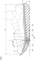
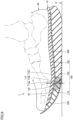
- Fig. 1 is a cross-sectional view schematically illustrating a shoe in one embodiment of the present disclosure.
- Fig. 2 is a plan view of a sole.
- Fig. 2 shows a sole 10 for the right foot, but the sole 10 is also applicable to the left foot.
- the sole for the left foot is in a shape symmetrical with or substantially similar to the sole for the right foot.
- the shoe 1 in the present embodiment is suitable, for example, for running, but can also be applicable to other sports shoes or walking shoes, and the use of the shoe 1 is not limited.
- the shoe 1 includes the sole 10 and an upper 20.
- the upper 20 is connected to the sole 10.
- the upper 20 and the sole 10 provide an accommodation space for a wearer's foot.
- the upper 20 covers an upper surface of the wearer's foot.
- the sole 10 constitutes a part of the shoe 1.
- the sole 10 is connected to a lower portion of the upper 20.
- the sole 10 is connected to the upper 20 by adhesion, for example.
- the sole 10 includes a midsole 100, an outsole 200, and a plate 300.
- the midsole 100 has a cushioning function at the time of landing, a repulsive function at the time of taking off, and the like.
- the midsole 100 is preferably made of resin, rubber, or the like having an appropriate strength and excellent buffering property.
- the midsole 100 has an upper connection surface 100S to which the upper 20 is connected. As illustrated in Fig. 1 , the midsole 100 includes a first support portion 110, a second support portion 120, and a buffer layer 130.
- the first support portion 110 supports a front portion of an MP joint of the wearer's foot. As illustrated in Fig. 1 , a surface of a front end portion of the first support portion 110 constitutes a part of the upper connection surface 100S.
- the first support portion 110 is made of, for example, a resin foam. Examples of the resin constituting the first support portion 110 include a polyamide-based thermoplastic elastomer (TPA, TPAE), a thermoplastic polyurethane (TPU), a polyester-based thermoplastic elastomer (TPEE), and an ethylene-vinyl acetate copolymer (EVA).
- TPA polyamide-based thermoplastic elastomer
- TPU thermoplastic polyurethane
- TPEE polyester-based thermoplastic elastomer
- EVA ethylene-vinyl acetate copolymer
- the second support portion 120 has a shape extending rearward from the first support portion 110 in the foot length direction (vertical direction in Fig. 2 ) of the sole 10.
- the second support portion 120 supports a rear portion of the MP joint of the wearer's foot.
- the second support portion 120 is made of resin foam, for example.
- the resin constituting the second support portion 120 include a polyamide-based thermoplastic elastomer (TPA, TPAE), a thermoplastic polyurethane (TPU), a polyester-based thermoplastic elastomer (TPEE), and an ethylene-vinyl acetate copolymer (EVA).
- the foot length direction is a direction parallel to a shoe center SC (see Fig. 2 ).
- the shoe center SC is not limited to the center line of the shoe 1, and may be a line that overlaps a straight line passing through the center of the calcaneus of the standard wearer of the shoe 1 and a portion between the first toe and the second toe, and the thickness direction of the sole 10.
- the first support portion 110 has an elastic modulus lower than an elastic modulus of the second support portion 120.
- a ratio of the elastic modulus of the first support portion 110 to the elastic modulus of the second support portion 120 is preferably set to a value greater than or equal to 0.3 times and less than 1 time, and more preferably greater than or equal to 0.3 times and less than 0.75 times.
- the elastic modulus of the first support portion 110 is preferably set to a value greater than or equal to 0.25 MPa and less than or equal to 0.9 MPa, and more preferably greater than or equal to 0.25 MPa and less than or equal to 0.5 MPa.
- the elastic modulus of the first support portion 110 is measured, for example, as follows. That is, a test piece having a predetermined shape (for example, a columnar shape) is cut out from the first support portion 110, and measurement is performed by compressing the test piece from both sides in a direction corresponding to the thickness direction of the sole.
- the elastic modulus of the second support portion 120 is also measured in the same manner.
- the elastic modulus can also be measured by compressing the test pieces from both sides in a direction in which a load is assumed to be applied at the time of wearing. The elastic modulus is calculated as an initial gradient until the strain reaches 5% in the stress-strain curve obtained by the above measurement.
- a boundary portion 115 (see Fig. 1 ) between the first support portion 110 and the second support portion 120 passes through at least a thenar region R1 (see Figs. 1 and 2 ).
- the thenar region R1 is a region that overlaps the thumb MP joint of the standard wearer's foot of the shoe 1 in the thickness direction.
- the thenar region R1 is a region surrounded by a first portion P1, a second portion P2, a third portion P3, and a fourth portion P4. In Figs. 1 and 2 , the thenar region R1 is indicated by a dot pattern.
- the first portion P1 is located on the shoe center SC, and is located at a position of a first length L11 rearward from a front end portion of the midsole 100 in the foot length direction.
- the first length L11 is 15% of a total length L10 of the upper connection surface 100S.
- the second portion P2 is located on the shoe center SC, and is located at a position of a second length L12 rearward from the front end portion in the foot length direction.
- the second length L12 is 35% of the total length L10 of the upper connection surface 100S.
- the third portion P3 is an intersection of a straight line orthogonal to the shoe center SC and passing through the first portion P1 and an end portion on the inner foot side of the midsole 100 in the foot width direction of the sole 10 (left and right direction in Fig. 2 ).
- the fourth portion P4 is an intersection of a straight line orthogonal to the shoe center SC and passing through the second portion P2 and an end portion on the inner foot side of the midsole 100 in the foot width direction.
- the boundary portion 115 is provided at a position substantially overlapping all MP joints of the wearer's foot in the thickness direction over the entire region from an upper end to a lower end of the boundary portion 115.
- the "position substantially overlapping” includes not only a position completely overlapping the MP joint in the thickness direction but also a position shifted from that position by a predetermined length in the foot length direction.
- the buffer layer 130 is disposed above the first support portion 110 and the second support portion 120.
- the buffer layer 130 has a shape extending in the foot length direction across the boundary portion 115 between the first support portion 110 and the second support portion 120.
- a surface of the buffer layer 130 constitutes the upper connection surface 100S together with the surface of the front end portion of the first support portion 110.
- the buffer layer 130 is made of resin foam or the like. Examples of the resin constituting the buffer layer 130 include a polyamide-based thermoplastic elastomer (TPA, TPAE), a thermoplastic polyurethane (TPU), a polyester-based thermoplastic elastomer (TPEE), and an ethylene-vinyl acetate copolymer (EVA).
- TPA polyamide-based thermoplastic elastomer
- TPU thermoplastic polyurethane
- TPEE polyester-based thermoplastic elastomer
- EVA ethylene-vinyl acetate copolymer
- An elastic modulus of the buffer layer 130 may be equal to or smaller than the elastic modulus of the second support portion 120.
- a ratio of the elastic modulus of the buffer layer 130 to the elastic modulus of the second support portion 120 is preferably set to a value greater than or equal to 0.25 times and less than or equal to 1 time, and more preferably greater than or equal to 0.25 times and less than or equal to 0.75 times.
- the buffer layer 130 has an overlapping portion 132 overlapping the MP joint of the wearer's foot in the thickness direction of the sole 10.
- a thickness of the overlapping portion 132 in a cross section of the sole 10 in a plane passing through the shoe center SC and parallel to the thickness direction is smaller than the thickness of the boundary portion 115.
- the thickness of the buffer layer 130 in the cross section of the sole 10 is smaller than the thicknesses of the first support portion 110 and the second support portion 120 over the entire region of the buffer layer 130 from a front end to a rear end.
- the outsole 200 is connected to a lower surface of the midsole 100.
- the outsole 200 is made of rubber, resin, or the like.
- the outsole 200 has a shape extending in the foot length direction across the boundary portion 115.
- the outsole 200 may cover the entire lower surface of the midsole 100, or may cover only a part of the midsole 100 as illustrated in Fig. 1 .
- the plate 300 is connected to upper surfaces of the first support portion 110 and the second support portion 120.
- the plate 300 has a shape extending in the foot length direction across the boundary portion 115. As illustrated in Fig. 1 , the plate 300 is sandwiched between the first support portion 110 and the second support portion 120, and the buffer layer 130.
- the plate 300 has a flexural rigidity larger than a flexural rigidity of the first support portion 110 and a flexural rigidity of the second support portion 120.
- the flexural rigidity of the plate 300 is larger than a flexural rigidity of the buffer layer 130.
- the plate 300 has a function of increasing the flexural rigidity of the sole 10, a function of uniformly applying a load to portions of the midsole 100 located below the plate 300 (the first support portion 110 and the second support portion 120 in the present embodiment), and the like.
- the plate 300 is made of a fiber-reinforced resin or a non-fiber-reinforced resin.
- fiber used for the fiber-reinforced resin include carbon fiber, glass fiber, aramid fiber, Dyneema fiber (registered trademark), Zylon fiber (registered trademark), and boron fiber. In the present embodiment, carbon fibers are used as the fibers.
- a thickness of the plate 300 is smaller than the thickness of the first support portion 110, the thickness of the second support portion 120, and the thickness of the buffer layer 130.
- a large load does not act on the boundary portion 115 between the first support portion 110 and the second support portion 120 from the MP joint of the wearer's foot.
- a large load acts on the boundary portion 115 from the MP joint of the wearer's foot. Therefore, a particularly large compressive load acts on a portion in the vicinity of the boundary portion 115, that is, a front portion of the second support portion 120 and a rear portion of the first support portion 110.
- an amount of compressive deformation of the first support portion 110 is larger than an amount of compressive deformation of the second support portion 120. That is, at the time of taking off, an amount of sinking in a portion of the wearer's foot in front of the MP joint becomes relatively large.
- the load acting on the first support portion 110 and the second support portion 120 located below the plate 300 is made uniform, so that the deformation range of the first support portion 110 and the second support portion 120 becomes large as compared with the case where the plate 300 is not provided. Even when a large load acts on the sole 10, the bottom touch feeling felt by the wearer is reduced.
- the plate 300 improves the stability of the foot portion at the time of landing and taking off, and since the plate 300 is across the boundary portion 115, the wearer is less likely to feel a local change in hardness around the boundary portion 115.
- the thickness of the buffer layer 130 in the cross section of the sole 10 is smaller than the thicknesses of the first support portion 110 and the second support portion 120 over the entire region of the buffer layer 130 from the front end to the rear end.
- the amount of deformation of the first support portion 110 can be increased, and an effect of reducing the change in angle of the ankle joint from the time of landing to the time of taking off can be greatly received.
- the plate 300 may be omitted. Without the plate 300, even a wearer whose load applied to the sole 10 is relatively small can easily feel the effect that the change in angle of the ankle joint between the time of landing and the time of taking off decreases. In addition, since the plate 300 is not provided, a lightweight property of the sole 10 is improved.
- the plate 300 and the buffer layer 130 may be omitted. Without the plate 300 and the buffer layer 130, even a wearer whose load applied to the sole 10 is relatively small can easily feel the effect that the change in angle of the ankle joint between the time of landing and the time of taking off decreases.
- the buffer layer 130 may be disposed below the first support portion 110 and the second support portion 120.
- the plate 300 is disposed so as to be in contact with lower surfaces of the first support portion 110 and the second support portion 120.
- a connection surface between the buffer layer 130 and the plate 300 can be inclined from a forefoot portion to a heel portion, and the fall of the heel portion from the midfoot at the time of taking off is suppressed.
- the plate 300 may be omitted.
- the boundary portion 115 may have a shape gradually inclined forward in the foot length direction as proceeding downward in the thickness direction of the sole 10.
- the upper end of the boundary portion 115 is provided at the same position as the upper end of the boundary portion 115 in the above embodiment.
- the boundary portion 115 in the above embodiment is indicated by an alternate long and short dash line.
- the boundary portion 115 comes close to a direction perpendicular to a landing surface, and the amount of compressive deformation of the front portion of the second support portion 120 at the time of taking off increases. Therefore, a repulsive force from the second support portion 120 is largely secured. This is particularly noticeable for a wearer with a large kicking angle.
- the boundary portion 115 may have a shape gradually inclined rearward in the foot length direction as proceeding downward in the thickness direction of the sole 10. Also in this example, the upper end of the boundary portion 115 is provided at the same position as the upper end of the boundary portion 115 in the above embodiment. In Fig. 8 , the boundary portion 115 in the above embodiment is indicated by an alternate long and short dash line.
- the boundary portion 115 may have a shape including at least one inflection point or vertex in a cross section in a plane parallel to a plane including the foot length direction and a thickness direction of the sole.
- the boundary portion 115 has an upper side surface 115a, an intermediate surface 115b, and a lower side surface 115c.
- the upper side surface 115a includes an upper end of the boundary portion 115 and is provided in parallel with the thickness direction.
- the intermediate surface 115b intersects with the upper side surface 115a.
- the intermediate surface 115b may be orthogonal to the upper side surface 115a.
- the intermediate surface 115b extends rearward from the upper side surface 115a.
- a boundary between the intermediate surface 115b and the upper side surface 115a is constituted by a curved surface.
- the lower side surface 115c intersects with the intermediate surface 115b.
- the lower side surface 115c extends downward from a rear end of the intermediate surface 115b.
- the lower side surface 115c has a shape gradually inclined forward in the foot length direction as proceeding downward in the thickness direction of the sole 10.
- a boundary between the lower side surface 115c and the intermediate surface 115b is constituted by a corner portion.
- the lower side surface 115c may be provided in parallel with the thickness direction.
- the boundary portion 115 may include a central boundary portion 115A and an end boundary portion 115B.
- the central boundary portion 115A is provided at a center in the foot width direction.
- the central boundary portion 115A has the same shape as that in the sixth modified example.
- the end boundary portion 115B is provided at an end portion in the foot width direction.
- the end boundary portion 115B has a shape gradually inclined forward in the foot length direction as proceeding downward in the thickness direction of the sole 10.
- the end boundary portion 115B may have a shape gradually inclined rearward in the foot length direction as proceeding downward in the thickness direction of the sole 10.
- bonding between the first support portion 110 and the second support portion 120 becomes stronger, and a bonding characteristic at the time of manufacturing is improved.
- the first support portion 110 may include a three-dimensional mesh structure 3A or 3B illustrated in Fig. 11 or Fig. 12 .
- This three-dimensional mesh structure is manufactured by, for example, three-dimensional additive manufacturing of a stereolithography method.
- Fig. 11 is a schematic diagram for illustration of a three-dimensional lattice structure of the first support portion 110.
- Fig. 12 is a schematic diagram for illustration of a three-dimensional lattice structure according to the structure shown in Fig. 11 .
- the three-dimensional mesh structure 3A shown in Fig. 11 has a plurality of unit structures 4A disposed so as to be repeatedly arranged.
- Each unit structure 4A has a three-dimensional lattice structure.
- the plurality of unit structures 4A are repeatedly arrayed regularly and continuously along each of a width direction (X direction in Fig. 11 ), a depth direction (Y direction in Fig. 11 ), and a height direction (Z direction in Fig. 11).
- Fig. 11 illustrates only some unit structures 4A adjacent to each other in the width direction, the depth direction, and the height direction.
- the unit structure 4A having a three-dimensional lattice structure has a three-dimensional shape in which a plurality of columnar portions 6 extending along a predetermined direction are connected to each other.
- the plurality of columnar portions 6 are configured such that adjacent columnar portions 6 intersect with the extending direction thereof, and thus providing a three-dimensional lattice structure.
- the unit structure 4A illustrated in Fig. 11 is called a fluorite type lattice. Note that a unit space 5A occupied by the unit structure 4A has a polyhedral shape, and the unit space 5A has a hexahedral shape in the unit structure 4A illustrated in Fig. 11 .
- each of the plurality of columnar portions 6 is configured to have a substantially columnar outer shape. Therefore, a cross-sectional shape orthogonal to the extending direction of each of the plurality of columnar portions 6 is substantially circular. Further, in the three-dimensional mesh structure 3A illustrated in Fig. 11 , a thickness of each of the plurality of columnar portions 6 continuously changes along the extending direction thereof. Specifically, each columnar portion 6 has a shape in which the thickness is large at a connection portion with another columnar portion 6 adjacent to each columnar portion 6, and the thickness decreases as a distance from the connection portion increases. According to this configuration, it is possible to enhance durability while maintaining flexibility.
- a three-dimensional mesh structure 3B illustrated in Fig. 12 has a three-dimensional structure having a configuration according to the structure illustrated in Fig. 11 , and a unit structure 4B is a fluorite type lattice, and a unit space 5B occupied by the unit structure 4B has a hexahedron shape.
- a thickness of each of the plurality of columnar portions 6 is uniformly configured along the extending direction thereof.
- various structures other than the structures shown in Figs. 11 and 12 can be adopted, and such as a rectangular parallelepiped lattice, a diamond lattice, an octahedral lattice, a double pyramid lattice, or a lattice to which various supports are added can be applied, for example.
- the three-dimensional mesh structures 3A and 3B can also be made of a polymer composition.
- examples of the polymer to be contained in the polymer composition include olefin-based polymers such as olefin-based elastomers and olefin-based resins.
- olefin-based polymer examples include polyolefins such as polyethylene (for example, linear low density polyethylene (LLDPE), high density polyethylene (HDPE), and the like), polypropylene, an ethylene-propylene copolymer, a propylene -1 hexene copolymer, a propylene -4 methyl -1 pentene copolymer, a propylene -1 butene copolymer, an ethylene -1 hexene copolymer, an ethylene -4 methyl-pentene copolymer, an ethylene -1 butene copolymer, a 1-butene -1 hexene copolymer, a 1-butene -4 methyl-pentene, an ethylene-methacrylic acid copolymer, an ethylene-methyl methacrylate copolymer, an ethylene-ethyl methacrylate copolymer, an ethylene-butyl methacrylate copolymer, an
- the polymer may be, for example, an amide-based polymer such as an amide-based elastomer or an amide-based resin.
- amide-based polymer examples include polyamide 6, polyamide 11, polyamide 12, polyamide 66, and polyamide 610.
- the polymer may be, for example, an ester-based polymer such as an ester-based elastomer or an ester-based resin.
- ester-based polymer examples include polyethylene terephthalate and polybutylene terephthalate.
- the polymer may be, for example, a urethane-based polymer such as a urethane-based elastomer or a urethane-based resin.
- a urethane-based polymer such as a urethane-based elastomer or a urethane-based resin.
- the urethane-based polymer include polyester-based polyurethanes and polyether-based polyurethanes, and in particular, urethane acrylates can be suitably used.
- the polymer may be, for example, a styrene-based polymer such as a styrene-based elastomer or a styrene-based resin.
- styrene-based elastomer examples include a styrene-ethylene-butylene copolymer (SEB), a styrene-butadiene-styrene copolymer (SBS), a hydrogenated product of SBS (styrene-ethylene-butylene-styrene copolymer (SEBS)), a styrene-isoprene-styrene copolymer (SIS), a hydrogenated product of SIS (styrene-ethylene-propylene-styrene copolymer (SEPS)), a styrene-isobutylene-styrene copolymer (SIBS), styrene-butadiene
- the polymer may be, for example, an acrylic polymer such as polymethyl methacrylate, a urethane-based acrylic polymer, a polyester-based acrylic polymer, a polyether-based acrylic polymer, a polycarbonate-based acrylic polymer, an epoxy-based acrylic polymer, a conjugated diene polymerization-based acrylic polymer and hydrogenated products thereof, a urethane-based methacrylic polymer, a polyester-based methacrylic polymer, a polyether-based methacrylic polymer, a polycarbonate-based methacrylic polymer, an epoxy-based methacrylic polymer, a conjugated diene polymerization-based methacrylic polymer and hydrogenated products thereof, a polyvinyl chloride-based resin, a silicone-based elastomer, a butadiene rubber (BR), an isoprene rubber (IR), a chloroprene (CR), a natural rubber (NR), a styrene buta
- a large load acts on the sole from a front portion of the MP joint of the wearer's foot.
- the elastic modulus of the first support portion is lower than the elastic modulus of the second support portion, and the boundary portion between the first support portion and the second support portion passes through the thenar region that is the region overlapping the thenar eminence of the standard wearer's foot, so that the first support portion is compressed and deformed relatively largely at the time of taking off.
- a decrease in the angle of the ankle joint of the wearer at the time of taking off is suppressed, and thus a change in the angle of the ankle joint from the time of landing to the time of taking off is reduced. Therefore, a load on the foot during traveling or the like is reduced.
- boundary portion includes:
- first support portion and the second support portion are prevented from being separated from each other at the central boundary portion, and a repulsive force from the front portion of the second support layer at the time of taking off increases at the end boundary portion.
- the wearer since the buffering property at the time of landing is improved, and since the buffer layer is disposed across the boundary portion, the wearer is less likely to feel a local change in hardness around the boundary portion.
- the buffering effect immediately below the foot portion can be enhanced, the amount of deformation of the first support portion can be increased, and the effect of reducing the change in the angle of the ankle joint from the time of landing to the time of taking off can be enhanced.
- the plate improves the stability of the foot portion at the time of landing and taking off, and since the plate is across the boundary portion, the wearer is less likely to feel a local change in hardness around the boundary portion.
- the loads acting on the first support portion and the second support portion are made uniform.
- the three-dimensional mesh structure easily adjust the space factor as compared with a resin foam, in this aspect, a difference between the elastic modulus of the first support portion and the elastic modulus of the second support portion can be easily designed.
- a shoe including:
Landscapes
- Health & Medical Sciences (AREA)
- General Health & Medical Sciences (AREA)
- Epidemiology (AREA)
- Public Health (AREA)
- Chemical & Material Sciences (AREA)
- Engineering & Computer Science (AREA)
- Materials Engineering (AREA)
- Physical Education & Sports Medicine (AREA)
- Footwear And Its Accessory, Manufacturing Method And Apparatuses (AREA)
Abstract
Description
- This nonprovisional application is based on
Japanese Patent Application No. 2022-140847 filed on September 5, 2022 - The present disclosure relates to a sole and a shoe.
- Shoes worn in sports and the like are required to reduce fatigue of the feet during running and exercising. For example,
WO 2020/136916 A discloses a shoe capable of reducing a burden on an ankle joint. The sole of the shoe includes a rear bottom surface portion that, when placed on the flat virtual plane, comes into contact with the virtual plane, a toe portion having a height from the virtual plane that is greater than or equal to 170% and less than or equal to 250% with respect to a thickness dimension in the rear bottom surface portion, and a front bottom surface portion that is continuous with a front portion of the rear bottom surface portion, extends to the toe portion in a curved manner, and is separated from the virtual plane. - In the shoe described in
WO 2020/136916 A , it is desirable to further reduce the burden on the foot by suppressing the movement of the ankle joint from the time of landing to the time of taking off. - An object of the present disclosure is to provide a sole and a shoe capable of reducing a change in angle of an ankle joint from landing to taking off
- A sole according to one aspect of the present disclosure constitutes a part of a shoe, and includes: a midsole including an upper connection surface to which an upper is connected and that is configured to support a wearer's foot, wherein the midsole includes: a first support portion that is configured to support a front portion of an MP joint of the wearer's foot; and a second support portion that is configured to support a rear portion of the MP joint of the wearer's foot, the second support portion having a shape extending rearward from the first support portion in a foot length direction of the sole, the first support portion has an elastic modulus lower than an elastic modulus of the second support portion, the midsole includes a thenar region surrounded by a first portion, a second portion, a third portion, and a fourth portion, the first portion being located on a shoe center and located at a position rearward from a front end portion of the midsole in the foot length direction by a length of 15% of a total length of the upper connection surface; the second portion being located on the shoe center and located at a position rearward from the front end portion in the foot length direction by a length of 35% of a total length of the upper connection surface; the third portion corresponding to an intersection of a straight line that is orthogonal to the shoe center and passes through the first portion and an end portion on an inner foot side of the midsole in a foot width direction of the sole; and the fourth portion corresponding to an intersection of a straight line that is orthogonal to the shoe center and passes through the second portion and an end portion on an inner foot side of the midsole in the foot width direction, and a boundary portion between the first support portion and the second support portion passes through the thenar region.
- Further, a shoe according to one aspect of the present disclosure includes: the sole; and the upper connected to the sole and providing, together with the sole, an accommodation space for the wearer's foot.
- The foregoing and other objects, features, aspects and advantages of the present disclosure will become more apparent from the following detailed description of the present disclosure when taken in conjunction with the accompanying drawings.
-
-
Fig. 1 is a cross-sectional view schematically illustrating a shoe in one embodiment of the present disclosure. -
Fig. 2 is a plan view of a sole. -
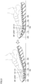
Fig. 3 is a diagram schematically illustrating a process from landing to taking off. -
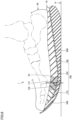
Fig. 4 is a cross-sectional view schematically illustrating a modified example of the sole. -
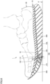
Fig. 5 is a cross-sectional view schematically illustrating a modified example of the sole. -
Fig. 6 is a cross-sectional view schematically illustrating a modified example of the sole. -
Fig. 7 is a cross-sectional view schematically illustrating a modified example of a boundary portion. -
Fig. 8 is a cross-sectional view schematically illustrating a modified example of the boundary portion. -
Fig. 9 is a cross-sectional view schematically illustrating a modified example of the boundary portion. -
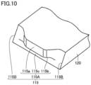
Fig. 10 is a perspective view schematically illustrating the boundary portion illustrated inFig. 9 . -
Fig. 11 is a schematic diagram for illustration of a modified example of a first support portion. -
Fig. 12 is a schematic diagram for illustration of a modified example of the first support portion. - An embodiment of the present disclosure will be described with reference to the drawings. In the drawings hereinafter referred to, the same or corresponding members are denoted by the same reference numerals. In the following description, terms such as a foot length direction, a foot width direction, a front side, and a rear side are used. Terms indicating these directions indicate directions as viewed from a viewpoint of a wearer wearing a
shoe 1 placed on a flat surface P (seeFig. 1 ) such as the ground. For example, the front side refers to a toe side and the rear side refers to a heel side. In addition, an inner side or an inner foot side refers to a side of the first toe (thumb) of the foot in the foot width direction, and an outer side or an outer foot side refers to a side of the fifth toe of the foot in the foot width direction. -
Fig. 1 is a cross-sectional view schematically illustrating a shoe in one embodiment of the present disclosure.Fig. 2 is a plan view of a sole.Fig. 2 shows a sole 10 for the right foot, but the sole 10 is also applicable to the left foot. In this case, the sole for the left foot is in a shape symmetrical with or substantially similar to the sole for the right foot. - The
shoe 1 in the present embodiment is suitable, for example, for running, but can also be applicable to other sports shoes or walking shoes, and the use of theshoe 1 is not limited. - As illustrated in
Fig. 1 , theshoe 1 includes the sole 10 and an upper 20. - The upper 20 is connected to the sole 10. The upper 20 and the sole 10 provide an accommodation space for a wearer's foot. The upper 20 covers an upper surface of the wearer's foot.
- The sole 10 constitutes a part of the
shoe 1. The sole 10 is connected to a lower portion of the upper 20. The sole 10 is connected to the upper 20 by adhesion, for example. As shown inFig. 1 , the sole 10 includes amidsole 100, anoutsole 200, and aplate 300. - The
midsole 100 has a cushioning function at the time of landing, a repulsive function at the time of taking off, and the like. Themidsole 100 is preferably made of resin, rubber, or the like having an appropriate strength and excellent buffering property. Themidsole 100 has anupper connection surface 100S to which the upper 20 is connected. As illustrated inFig. 1 , themidsole 100 includes afirst support portion 110, asecond support portion 120, and abuffer layer 130. - The
first support portion 110 supports a front portion of an MP joint of the wearer's foot. As illustrated inFig. 1 , a surface of a front end portion of thefirst support portion 110 constitutes a part of theupper connection surface 100S. Thefirst support portion 110 is made of, for example, a resin foam. Examples of the resin constituting thefirst support portion 110 include a polyamide-based thermoplastic elastomer (TPA, TPAE), a thermoplastic polyurethane (TPU), a polyester-based thermoplastic elastomer (TPEE), and an ethylene-vinyl acetate copolymer (EVA). - The
second support portion 120 has a shape extending rearward from thefirst support portion 110 in the foot length direction (vertical direction inFig. 2 ) of the sole 10. Thesecond support portion 120 supports a rear portion of the MP joint of the wearer's foot. Thesecond support portion 120 is made of resin foam, for example. Examples of the resin constituting thesecond support portion 120 include a polyamide-based thermoplastic elastomer (TPA, TPAE), a thermoplastic polyurethane (TPU), a polyester-based thermoplastic elastomer (TPEE), and an ethylene-vinyl acetate copolymer (EVA). - Here, the foot length direction is a direction parallel to a shoe center SC (see
Fig. 2 ). The shoe center SC is not limited to the center line of theshoe 1, and may be a line that overlaps a straight line passing through the center of the calcaneus of the standard wearer of theshoe 1 and a portion between the first toe and the second toe, and the thickness direction of the sole 10. - The
first support portion 110 has an elastic modulus lower than an elastic modulus of thesecond support portion 120. A ratio of the elastic modulus of thefirst support portion 110 to the elastic modulus of thesecond support portion 120 is preferably set to a value greater than or equal to 0.3 times and less than 1 time, and more preferably greater than or equal to 0.3 times and less than 0.75 times. Specifically, the elastic modulus of thefirst support portion 110 is preferably set to a value greater than or equal to 0.25 MPa and less than or equal to 0.9 MPa, and more preferably greater than or equal to 0.25 MPa and less than or equal to 0.5 MPa. - The elastic modulus of the
first support portion 110 is measured, for example, as follows. That is, a test piece having a predetermined shape (for example, a columnar shape) is cut out from thefirst support portion 110, and measurement is performed by compressing the test piece from both sides in a direction corresponding to the thickness direction of the sole. The elastic modulus of thesecond support portion 120 is also measured in the same manner. Alternatively, the elastic modulus can also be measured by compressing the test pieces from both sides in a direction in which a load is assumed to be applied at the time of wearing. The elastic modulus is calculated as an initial gradient until the strain reaches 5% in the stress-strain curve obtained by the above measurement. - A boundary portion 115 (see
Fig. 1 ) between thefirst support portion 110 and thesecond support portion 120 passes through at least a thenar region R1 (seeFigs. 1 and2 ). The thenar region R1 is a region that overlaps the thumb MP joint of the standard wearer's foot of theshoe 1 in the thickness direction. The thenar region R1 is a region surrounded by a first portion P1, a second portion P2, a third portion P3, and a fourth portion P4. InFigs. 1 and2 , the thenar region R1 is indicated by a dot pattern. - The first portion P1 is located on the shoe center SC, and is located at a position of a first length L11 rearward from a front end portion of the
midsole 100 in the foot length direction. The first length L11 is 15% of a total length L10 of theupper connection surface 100S. - The second portion P2 is located on the shoe center SC, and is located at a position of a second length L12 rearward from the front end portion in the foot length direction. The second length L12 is 35% of the total length L10 of the
upper connection surface 100S. - The third portion P3 is an intersection of a straight line orthogonal to the shoe center SC and passing through the first portion P1 and an end portion on the inner foot side of the
midsole 100 in the foot width direction of the sole 10 (left and right direction inFig. 2 ). - The fourth portion P4 is an intersection of a straight line orthogonal to the shoe center SC and passing through the second portion P2 and an end portion on the inner foot side of the
midsole 100 in the foot width direction. - An entire region of the
boundary portion 115 on the inner side (the thumb side) in the foot width direction in the thickness direction passes through the thenar region R1. In the present embodiment, theboundary portion 115 is provided at a position substantially overlapping all MP joints of the wearer's foot in the thickness direction over the entire region from an upper end to a lower end of theboundary portion 115. The "position substantially overlapping" includes not only a position completely overlapping the MP joint in the thickness direction but also a position shifted from that position by a predetermined length in the foot length direction. - The
buffer layer 130 is disposed above thefirst support portion 110 and thesecond support portion 120. Thebuffer layer 130 has a shape extending in the foot length direction across theboundary portion 115 between thefirst support portion 110 and thesecond support portion 120. A surface of thebuffer layer 130 constitutes theupper connection surface 100S together with the surface of the front end portion of thefirst support portion 110. Thebuffer layer 130 is made of resin foam or the like. Examples of the resin constituting thebuffer layer 130 include a polyamide-based thermoplastic elastomer (TPA, TPAE), a thermoplastic polyurethane (TPU), a polyester-based thermoplastic elastomer (TPEE), and an ethylene-vinyl acetate copolymer (EVA). An elastic modulus of thebuffer layer 130 may be equal to or smaller than the elastic modulus of thesecond support portion 120. A ratio of the elastic modulus of thebuffer layer 130 to the elastic modulus of thesecond support portion 120 is preferably set to a value greater than or equal to 0.25 times and less than or equal to 1 time, and more preferably greater than or equal to 0.25 times and less than or equal to 0.75 times. - As shown in
Fig. 1 , thebuffer layer 130 has an overlappingportion 132 overlapping the MP joint of the wearer's foot in the thickness direction of the sole 10. A thickness of the overlappingportion 132 in a cross section of the sole 10 in a plane passing through the shoe center SC and parallel to the thickness direction is smaller than the thickness of theboundary portion 115. In the present embodiment, as shown inFig. 1 , the thickness of thebuffer layer 130 in the cross section of the sole 10 is smaller than the thicknesses of thefirst support portion 110 and thesecond support portion 120 over the entire region of thebuffer layer 130 from a front end to a rear end. - The
outsole 200 is connected to a lower surface of themidsole 100. Theoutsole 200 is made of rubber, resin, or the like. Theoutsole 200 has a shape extending in the foot length direction across theboundary portion 115. Theoutsole 200 may cover the entire lower surface of themidsole 100, or may cover only a part of themidsole 100 as illustrated inFig. 1 . - The
plate 300 is connected to upper surfaces of thefirst support portion 110 and thesecond support portion 120. Theplate 300 has a shape extending in the foot length direction across theboundary portion 115. As illustrated inFig. 1 , theplate 300 is sandwiched between thefirst support portion 110 and thesecond support portion 120, and thebuffer layer 130. Theplate 300 has a flexural rigidity larger than a flexural rigidity of thefirst support portion 110 and a flexural rigidity of thesecond support portion 120. The flexural rigidity of theplate 300 is larger than a flexural rigidity of thebuffer layer 130. Theplate 300 has a function of increasing the flexural rigidity of the sole 10, a function of uniformly applying a load to portions of themidsole 100 located below the plate 300 (thefirst support portion 110 and thesecond support portion 120 in the present embodiment), and the like. Theplate 300 is made of a fiber-reinforced resin or a non-fiber-reinforced resin. Examples of fiber used for the fiber-reinforced resin include carbon fiber, glass fiber, aramid fiber, Dyneema fiber (registered trademark), Zylon fiber (registered trademark), and boron fiber. In the present embodiment, carbon fibers are used as the fibers. A thickness of theplate 300 is smaller than the thickness of thefirst support portion 110, the thickness of thesecond support portion 120, and the thickness of thebuffer layer 130. - Next, changes in the shapes of the
first support portion 110 and thesecond support portion 120 from the time of landing to the time of taking off will be described with reference toFig. 3 . - From the time of landing to the time before taking off, a large load does not act on the
boundary portion 115 between thefirst support portion 110 and thesecond support portion 120 from the MP joint of the wearer's foot. On the other hand, at the time of taking off, a large load acts on theboundary portion 115 from the MP joint of the wearer's foot. Therefore, a particularly large compressive load acts on a portion in the vicinity of theboundary portion 115, that is, a front portion of thesecond support portion 120 and a rear portion of thefirst support portion 110. - In the present embodiment, since the elastic modulus of the
first support portion 110 is lower than the elastic modulus of thesecond support portion 120, an amount of compressive deformation of thefirst support portion 110 is larger than an amount of compressive deformation of thesecond support portion 120. That is, at the time of taking off, an amount of sinking in a portion of the wearer's foot in front of the MP joint becomes relatively large. - As a result, a decrease in an angle of the ankle joint of the wearer at the time of taking off is suppressed, and thus a change in the angle of the ankle joint from the time of landing to the time of taking off is reduced. Therefore, a load on the foot during traveling or the like is reduced.
- In particular, at the time of taking off, the load acting on the
first support portion 110 and thesecond support portion 120 located below theplate 300 is made uniform, so that the deformation range of thefirst support portion 110 and thesecond support portion 120 becomes large as compared with the case where theplate 300 is not provided. Even when a large load acts on the sole 10, the bottom touch feeling felt by the wearer is reduced. Theplate 300 improves the stability of the foot portion at the time of landing and taking off, and since theplate 300 is across theboundary portion 115, the wearer is less likely to feel a local change in hardness around theboundary portion 115. - Furthermore, in the above embodiment, the thickness of the
buffer layer 130 in the cross section of the sole 10 is smaller than the thicknesses of thefirst support portion 110 and thesecond support portion 120 over the entire region of thebuffer layer 130 from the front end to the rear end. As a result, the amount of deformation of thefirst support portion 110 can be increased, and an effect of reducing the change in angle of the ankle joint from the time of landing to the time of taking off can be greatly received. - Hereinafter, modified examples of the above embodiment will be described with reference to
Figs. 4 to 12 . - As shown in
Fig. 4 , theplate 300 may be omitted. Without theplate 300, even a wearer whose load applied to the sole 10 is relatively small can easily feel the effect that the change in angle of the ankle joint between the time of landing and the time of taking off decreases. In addition, since theplate 300 is not provided, a lightweight property of the sole 10 is improved. - As illustrated in
Fig. 5 , theplate 300 and thebuffer layer 130 may be omitted. Without theplate 300 and thebuffer layer 130, even a wearer whose load applied to the sole 10 is relatively small can easily feel the effect that the change in angle of the ankle joint between the time of landing and the time of taking off decreases. - As illustrated in
Fig. 6 , thebuffer layer 130 may be disposed below thefirst support portion 110 and thesecond support portion 120. In this case, theplate 300 is disposed so as to be in contact with lower surfaces of thefirst support portion 110 and thesecond support portion 120. As a result, a connection surface between thebuffer layer 130 and theplate 300 can be inclined from a forefoot portion to a heel portion, and the fall of the heel portion from the midfoot at the time of taking off is suppressed. In this example, theplate 300 may be omitted. - As shown in
Fig. 7 , theboundary portion 115 may have a shape gradually inclined forward in the foot length direction as proceeding downward in the thickness direction of the sole 10. In this example, the upper end of theboundary portion 115 is provided at the same position as the upper end of theboundary portion 115 in the above embodiment. InFig. 7 , theboundary portion 115 in the above embodiment is indicated by an alternate long and short dash line. - In this aspect, when entire the sole 10 is inclined forward at the time of taking off, the
boundary portion 115 comes close to a direction perpendicular to a landing surface, and the amount of compressive deformation of the front portion of thesecond support portion 120 at the time of taking off increases. Therefore, a repulsive force from thesecond support portion 120 is largely secured. This is particularly noticeable for a wearer with a large kicking angle. - As shown in
Fig. 8 , theboundary portion 115 may have a shape gradually inclined rearward in the foot length direction as proceeding downward in the thickness direction of the sole 10. Also in this example, the upper end of theboundary portion 115 is provided at the same position as the upper end of theboundary portion 115 in the above embodiment. InFig. 8 , theboundary portion 115 in the above embodiment is indicated by an alternate long and short dash line. - In this aspect, since the
boundary portion 115 comes close to a landing point in the vicinity of the landing surface of the sole 10, an impact buffering property at the time of landing is increased. - As illustrated in
Fig. 9 , theboundary portion 115 may have a shape including at least one inflection point or vertex in a cross section in a plane parallel to a plane including the foot length direction and a thickness direction of the sole. In this example, theboundary portion 115 has anupper side surface 115a, anintermediate surface 115b, and alower side surface 115c. - The
upper side surface 115a includes an upper end of theboundary portion 115 and is provided in parallel with the thickness direction. - The
intermediate surface 115b intersects with theupper side surface 115a. - The
intermediate surface 115b may be orthogonal to theupper side surface 115a. Theintermediate surface 115b extends rearward from theupper side surface 115a. A boundary between theintermediate surface 115b and theupper side surface 115a is constituted by a curved surface. - The
lower side surface 115c intersects with theintermediate surface 115b. - The
lower side surface 115c extends downward from a rear end of theintermediate surface 115b. Thelower side surface 115c has a shape gradually inclined forward in the foot length direction as proceeding downward in the thickness direction of the sole 10. A boundary between thelower side surface 115c and theintermediate surface 115b is constituted by a corner portion. Thelower side surface 115c may be provided in parallel with the thickness direction. - In this aspect, since an area of the
boundary portion 115 is secured, thefirst support portion 110 and thesecond support portion 120 are prevented from being separated from each other. - As illustrated in
Fig. 10 , theboundary portion 115 may include acentral boundary portion 115A and anend boundary portion 115B. - The
central boundary portion 115A is provided at a center in the foot width direction. Thecentral boundary portion 115A has the same shape as that in the sixth modified example. - The
end boundary portion 115B is provided at an end portion in the foot width direction. As in the fourth modified example, theend boundary portion 115B has a shape gradually inclined forward in the foot length direction as proceeding downward in the thickness direction of the sole 10. As in the fifth modified example, theend boundary portion 115B may have a shape gradually inclined rearward in the foot length direction as proceeding downward in the thickness direction of the sole 10. - In this aspect, bonding between the
first support portion 110 and thesecond support portion 120 becomes stronger, and a bonding characteristic at the time of manufacturing is improved. - The
first support portion 110 may include a three-dimensional mesh structure Fig. 11 or Fig. 12 . This three-dimensional mesh structure is manufactured by, for example, three-dimensional additive manufacturing of a stereolithography method.Fig. 11 is a schematic diagram for illustration of a three-dimensional lattice structure of thefirst support portion 110.Fig. 12 is a schematic diagram for illustration of a three-dimensional lattice structure according to the structure shown inFig. 11 . - The three-
dimensional mesh structure 3A shown inFig. 11 has a plurality ofunit structures 4A disposed so as to be repeatedly arranged. Eachunit structure 4A has a three-dimensional lattice structure. The plurality ofunit structures 4A are repeatedly arrayed regularly and continuously along each of a width direction (X direction inFig. 11 ), a depth direction (Y direction inFig. 11 ), and a height direction (Z direction inFig. 11). Fig. 11 illustrates only someunit structures 4A adjacent to each other in the width direction, the depth direction, and the height direction. - The
unit structure 4A having a three-dimensional lattice structure has a three-dimensional shape in which a plurality ofcolumnar portions 6 extending along a predetermined direction are connected to each other. The plurality ofcolumnar portions 6 are configured such that adjacentcolumnar portions 6 intersect with the extending direction thereof, and thus providing a three-dimensional lattice structure. Theunit structure 4A illustrated inFig. 11 is called a fluorite type lattice. Note that aunit space 5A occupied by theunit structure 4A has a polyhedral shape, and theunit space 5A has a hexahedral shape in theunit structure 4A illustrated inFig. 11 . - In the three-
dimensional mesh structure 3A shown inFig. 11 , each of the plurality ofcolumnar portions 6 is configured to have a substantially columnar outer shape. Therefore, a cross-sectional shape orthogonal to the extending direction of each of the plurality ofcolumnar portions 6 is substantially circular. Further, in the three-dimensional mesh structure 3A illustrated inFig. 11 , a thickness of each of the plurality ofcolumnar portions 6 continuously changes along the extending direction thereof. Specifically, eachcolumnar portion 6 has a shape in which the thickness is large at a connection portion with anothercolumnar portion 6 adjacent to eachcolumnar portion 6, and the thickness decreases as a distance from the connection portion increases. According to this configuration, it is possible to enhance durability while maintaining flexibility. - A three-
dimensional mesh structure 3B illustrated inFig. 12 has a three-dimensional structure having a configuration according to the structure illustrated inFig. 11 , and aunit structure 4B is a fluorite type lattice, and aunit space 5B occupied by theunit structure 4B has a hexahedron shape. However, in the three-dimensional mesh structure 3B, unlike the structure shown inFig. 11 , a thickness of each of the plurality ofcolumnar portions 6 is uniformly configured along the extending direction thereof. - Note that, as the
unit structures Figs. 11 and 12 can be adopted, and such as a rectangular parallelepiped lattice, a diamond lattice, an octahedral lattice, a double pyramid lattice, or a lattice to which various supports are added can be applied, for example. - In the three-dimensional mesh structure as described above, since a space factor can be easily adjusted as compared with a resin foam (foam material), a difference between the elastic modulus of the
first support portion 110 and the elastic modulus of thesecond support portion 120 can be easily designed. - The three-
dimensional mesh structures - The polymer may be, for example, an amide-based polymer such as an amide-based elastomer or an amide-based resin. Examples of the amide-based polymer include
polyamide 6, polyamide 11, polyamide 12, polyamide 66, and polyamide 610. - The polymer may be, for example, an ester-based polymer such as an ester-based elastomer or an ester-based resin. Examples of the ester-based polymer include polyethylene terephthalate and polybutylene terephthalate.
- The polymer may be, for example, a urethane-based polymer such as a urethane-based elastomer or a urethane-based resin. Examples of the urethane-based polymer include polyester-based polyurethanes and polyether-based polyurethanes, and in particular, urethane acrylates can be suitably used.
- The polymer may be, for example, a styrene-based polymer such as a styrene-based elastomer or a styrene-based resin. Examples of the styrene-based elastomer include a styrene-ethylene-butylene copolymer (SEB), a styrene-butadiene-styrene copolymer (SBS), a hydrogenated product of SBS (styrene-ethylene-butylene-styrene copolymer (SEBS)), a styrene-isoprene-styrene copolymer (SIS), a hydrogenated product of SIS (styrene-ethylene-propylene-styrene copolymer (SEPS)), a styrene-isobutylene-styrene copolymer (SIBS), styrene-butadiene-styrene-butadiene (SBSB), and styrene-butadiene-styrene-butadiene-styrene (SBSBS). Examples of the styrene-based resin include polystyrene, acrylonitrile styrene resin (AS), and acrylonitrile butadiene styrene resin (ABS).
- In addition, the polymer may be, for example, an acrylic polymer such as polymethyl methacrylate, a urethane-based acrylic polymer, a polyester-based acrylic polymer, a polyether-based acrylic polymer, a polycarbonate-based acrylic polymer, an epoxy-based acrylic polymer, a conjugated diene polymerization-based acrylic polymer and hydrogenated products thereof, a urethane-based methacrylic polymer, a polyester-based methacrylic polymer, a polyether-based methacrylic polymer, a polycarbonate-based methacrylic polymer, an epoxy-based methacrylic polymer, a conjugated diene polymerization-based methacrylic polymer and hydrogenated products thereof, a polyvinyl chloride-based resin, a silicone-based elastomer, a butadiene rubber (BR), an isoprene rubber (IR), a chloroprene (CR), a natural rubber (NR), a styrene butadiene rubber (SBR), an acrylonitrile butadiene rubber (NBR), a butyl rubber (IIR), and the like.
- It is understood by those skilled in the art that the exemplary embodiment described above is a specific example of the following aspects.
- A sole that constitutes a part of a shoe, the sole including:
- a midsole including an upper connection surface to which an upper is connected and that is configured to support a wearer's foot, wherein
- the midsole includes:
- a first support portion that is configured to support a front portion of an MP joint of the wearer's foot; and
- a second support portion that is configured to support a rear portion of the MP joint of the wearer's foot, the second support portion having a shape extending rearward from the first support portion in a foot length direction of the sole,
- the first support portion has an elastic modulus lower than an elastic modulus of the second support portion,
- the midsole includes a thenar region surrounded by a first portion, a second portion, a third portion, and a fourth portion, the first portion being located on a shoe center and located at a position rearward from a front end portion of the midsole in the foot length direction by a length of 15% of a total length of the upper connection surface; the second portion being located on the shoe center and located at a position rearward from the front end portion in the foot length direction by a length of 35% of a total length of the upper connection surface; the third portion corresponding to an intersection of a straight line that is orthogonal to the shoe center and passes through the first portion and an end portion on an inner foot side of the midsole in a foot width direction of the sole; and the fourth portion corresponding to an intersection of a straight line that is orthogonal to the shoe center and passes through the second portion and an end portion on an inner foot side of the midsole in the foot width direction, and
- a boundary portion between the first support portion and the second support portion passes through the thenar region.
- Generally, at the time of taking off in a running motion or the like, a large load acts on the sole from a front portion of the MP joint of the wearer's foot. In this sole, the elastic modulus of the first support portion is lower than the elastic modulus of the second support portion, and the boundary portion between the first support portion and the second support portion passes through the thenar region that is the region overlapping the thenar eminence of the standard wearer's foot, so that the first support portion is compressed and deformed relatively largely at the time of taking off. As a result, a decrease in the angle of the ankle joint of the wearer at the time of taking off is suppressed, and thus a change in the angle of the ankle joint from the time of landing to the time of taking off is reduced. Therefore, a load on the foot during traveling or the like is reduced.
- The sole according to
aspect 1, wherein - the boundary portion has a shape gradually inclined forward in the foot length direction as proceeding downward in a thickness direction of the sole.
- In this aspect, when the entire sole is inclined forward at the time of taking off, the boundary portion comes close to a direction perpendicular to a landing surface, and the amount of compressive deformation of the front portion of the second support portion at the time of taking off increases. Therefore, a repulsive force from the second support portion is largely secured. This is particularly noticeable for a wearer with a large kicking angle.
- The sole according to
aspect 1, wherein - the boundary portion has a shape gradually inclined rearward in the foot length direction as proceeding downward in a thickness direction of the sole.
- In this aspect, since the boundary portion comes close to the landing point in the vicinity of the landing surface of the sole, an impact buffering property at the time of landing is increased.
- The sole according to
aspect 1, wherein - the boundary portion has a shape including at least one inflection point or vertex in a cross section in a plane parallel to a plane including the foot length direction and a thickness direction of the sole.
- In this aspect, since an area of the boundary portion is secured, the first support portion and the second support portion are prevented from being separated from each other.
- The sole according to
aspect 1, wherein
the boundary portion includes: - a central boundary portion provided at a center in the foot width direction; and
- an end boundary portion provided at an end portion in the foot width direction,
- the central boundary portion has a shape including at least one inflection point or vertex in a cross section in a plane parallel to a plane including the foot length direction and a thickness direction of the sole, and
- the end boundary portion has a shape gradually inclined forward in the foot length direction as proceeding downward in the thickness direction of the sole.
- In this aspect, the first support portion and the second support portion are prevented from being separated from each other at the central boundary portion, and a repulsive force from the front portion of the second support layer at the time of taking off increases at the end boundary portion.
- The sole according to any one of
aspects 1 to 5, further including: - a buffer layer disposed above or below the first support portion and the second support portion, wherein
- the buffer layer has a shape extending along the foot length direction across the boundary portion.
- In this aspect, since the buffering property at the time of landing is improved, and since the buffer layer is disposed across the boundary portion, the wearer is less likely to feel a local change in hardness around the boundary portion.
- The sole according to
aspect 6, wherein - the buffer layer includes an overlapping portion that overlaps the boundary portion in a thickness direction of the sole, and
- a thickness of the overlapping portion is smaller than a thickness of the boundary portion in a cross section of the sole in a plane that passes through the shoe center and that is parallel to the thickness direction.
- In this aspect, the buffering effect immediately below the foot portion can be enhanced, the amount of deformation of the first support portion can be increased, and the effect of reducing the change in the angle of the ankle joint from the time of landing to the time of taking off can be enhanced.
- The sole according to any one of
aspects 1 to 7, further including: - a plate having a flexural rigidity greater than a flexural rigidity of the first support portion and a flexural rigidity of the second support portion, wherein
- the plate is disposed so as to be in contact with upper surfaces or lower surfaces of the first support portion and the second support portion, and has a shape extending along the foot length direction across the boundary portion.
- In this aspect, the plate improves the stability of the foot portion at the time of landing and taking off, and since the plate is across the boundary portion, the wearer is less likely to feel a local change in hardness around the boundary portion.
- The sole according to aspect 8, wherein
- the plate is disposed so as to be in contact with the upper surfaces of the first support portion and the second support portion.
- In this aspect, particularly at the time of taking off, the loads acting on the first support portion and the second support portion are made uniform.
- The sole according to any one of
aspects 1 to 9, wherein - the first support portion includes a three-dimensional mesh structure, and
- the second support portion includes resin foam.
- Since the three-dimensional mesh structure easily adjust the space factor as compared with a resin foam, in this aspect, a difference between the elastic modulus of the first support portion and the elastic modulus of the second support portion can be easily designed.
- A shoe including:
- the sole according to any one of
aspects 1 to 10; and - the upper connected to the sole and providing, together with the sole, an accommodation space for the wearer's foot.
- Although the present disclosure has been described and illustrated, it is understood that the embodiment disclosed herein is by way of illustration and example only and is not to be taken by way of limitation. The scope of the present invention is interpreted by the terms of the appended claims, and it is intended that meanings equivalent to the claims and all modifications within the scope are included.
Claims (11)
- A sole (10) that constitutes a part of a shoe (1), the sole comprising a midsole (100) including an upper connection surface (100S) to which an upper (20) is connected and that is configured to support a wearer's foot, wherein
the midsole includes:a first support portion (110) that is configured to support a front portion of an MP joint of the wearer's foot; anda second support portion (120) that is configured to support a rear portion of the MP joint of the wearer's foot, the second support portion having a shape extending rearward from the first support portion in a foot length direction of the sole,the first support portion has an elastic modulus lower than an elastic modulus of the second support portion,the midsole (100) includes a thenar region (R1) surrounded by a first portion (P1), a second portion (P2), a third portion (P3), and a fourth portion (P4), the first portion (P1) being located on a shoe center (SC) and located at a position rearward from a front end portion of the midsole in the foot length direction by a length of 15% of a total length of the upper connection surface; the second portion (P2) being located on the shoe center and located at a position rearward from the front end portion in the foot length direction by a length of 35% of a total length of the upper connection surface; the third portion (P3) corresponding to an intersection of a straight line that is orthogonal to the shoe center and passes through the first portion and an end portion on an inner foot side of the midsole in a foot width direction of the sole; and the fourth portion (P4) corresponding to an intersection of a straight line that is orthogonal to the shoe center and passes through the second portion and an end portion on an inner foot side of the midsole in the foot width direction, anda boundary portion (115) between the first support portion and the second support portion passes through the thenar region (R1). - The sole according to claim 1, wherein the boundary portion (115) has a shape gradually inclined forward in the foot length direction as proceeding downward in a thickness direction of the sole.
- The sole according to claim 1, wherein the boundary portion (115) has a shape gradually inclined rearward in the foot length direction as proceeding downward in a thickness direction of the sole.
- The sole according to claim 1, wherein the boundary portion (115) has a shape including at least one inflection point or vertex in a cross section in a plane parallel to a plane including the foot length direction and a thickness direction of the sole.
- The sole according to claim 1, wherein
the boundary portion (115) includes:a central boundary portion (115A) provided at a center in the foot width direction; andan end boundary portion (115B) provided at an end portion in the foot width direction,the central boundary portion has a shape including at least one inflection point or vertex in a cross section in a plane parallel to a plane including the foot length direction and a thickness direction of the sole, andthe end boundary portion has a shape gradually inclined forward in the foot length direction as proceeding downward in the thickness direction of the sole. - The sole according to claim 1, further comprising a buffer layer (130) disposed above or below the first support portion (110) and the second support portion (120), wherein
the buffer layer has a shape extending along the foot length direction across the boundary portion. - The sole according to claim 6, whereinthe buffer layer (130) includes an overlapping portion (132) that overlaps the boundary portion in a thickness direction of the sole, anda thickness of the overlapping portion is smaller than a thickness of the boundary portion in a cross section of the sole in a plane that passes through the shoe center and that is parallel to the thickness direction.
- The sole according to claim 1, further comprising a plate (300) having a flexural rigidity greater than a flexural rigidity of the first support portion and a flexural rigidity of the second support portion, wherein
the plate is disposed so as to be in contact with upper surfaces or lower surfaces of the first support portion and the second support portion, and has a shape extending along the foot length direction across the boundary portion. - The sole according to claim 8, wherein the plate (300) is disposed so as to be in contact with the upper surfaces of the first support portion and the second support portion.
- The sole according to claim 1, whereinthe first support portion (110) includes a three-dimensional mesh structure (3A), andthe second support portion includes resin foam.
- A shoe (1) comprising:the sole (10) according to any one of claims 1 to 10; andthe upper (20) connected to the sole and providing, together with the sole, an accommodation space for the wearer's foot.
Applications Claiming Priority (1)
| Application Number | Priority Date | Filing Date | Title |
|---|---|---|---|
| JP2022140847A JP2024036114A (en) | 2022-09-05 | 2022-09-05 | Soles and shoes |
Publications (2)
| Publication Number | Publication Date |
|---|---|
| EP4331422A1 true EP4331422A1 (en) | 2024-03-06 |
| EP4331422B1 EP4331422B1 (en) | 2026-04-01 |
Family
ID=87863587
Family Applications (1)
| Application Number | Title | Priority Date | Filing Date |
|---|---|---|---|
| EP23194377.0A Active EP4331422B1 (en) | 2022-09-05 | 2023-08-30 | Sole and shoe |
Country Status (4)
| Country | Link |
|---|---|
| US (1) | US12349767B2 (en) |
| EP (1) | EP4331422B1 (en) |
| JP (1) | JP2024036114A (en) |
| CN (1) | CN117643404A (en) |
Families Citing this family (3)
| Publication number | Priority date | Publication date | Assignee | Title |
|---|---|---|---|---|
| JP2024063412A (en) * | 2022-10-26 | 2024-05-13 | 株式会社アシックス | Soles and shoes |
| US12588737B2 (en) * | 2023-05-17 | 2026-03-31 | Saucony, Inc. | Footwear sole and related method of use |
| JP7742200B1 (en) * | 2025-03-31 | 2025-09-19 | 株式会社Oni | Shoes |
Citations (5)
| Publication number | Priority date | Publication date | Assignee | Title |
|---|---|---|---|---|
| US20160316853A1 (en) * | 2014-04-26 | 2016-11-03 | Mizuno Corporation | Sole Structure for a Sport Shoe |
| US20160353838A1 (en) * | 2015-06-05 | 2016-12-08 | Mizuno Corporation | Sole structure for shoes |
| WO2020136916A1 (en) | 2018-12-28 | 2020-07-02 | 株式会社アシックス | Shoe sole and shoe |
| EP3892147A1 (en) * | 2018-12-28 | 2021-10-13 | ASICS Corporation | Shoe |
| WO2021210045A1 (en) * | 2020-04-13 | 2021-10-21 | 株式会社アシックス | Sole and footwear |
Family Cites Families (24)
| Publication number | Priority date | Publication date | Assignee | Title |
|---|---|---|---|---|
| US1550715A (en) * | 1923-06-07 | 1925-08-25 | Edward E Stout | Shoe insole |
| US4731939A (en) * | 1985-04-24 | 1988-03-22 | Converse Inc. | Athletic shoe with external counter and cushion assembly |
| US4638576A (en) * | 1985-04-24 | 1987-01-27 | Converse Inc. | Athletic shoe with external counter and cushion assembly |
| FR2858525B1 (en) * | 2003-08-05 | 2006-01-27 | Jean Luc Rhenter | PLANT SOIL WITH SELECTIVE DAMPING |
| US20050086838A1 (en) * | 2003-10-24 | 2005-04-28 | Khantzis Carlos A. | Shoe sole to improve walking, sensory response of the toes, and help develop leg muscles |
| WO2005120275A2 (en) * | 2004-06-08 | 2005-12-22 | Keen Llc | Footwear with multi-piece midsole |
| US20100299969A1 (en) * | 2009-05-29 | 2010-12-02 | Liliana Paez | Layered footwear assembly with an arcuate undersurface |
| US8881428B2 (en) * | 2010-09-02 | 2014-11-11 | Nike, Inc. | Sole assembly for article of footwear with plural cushioning members |
| GB201112362D0 (en) * | 2011-07-18 | 2011-08-31 | Fitflop Ltd | An item of footwear |
| US8595956B2 (en) * | 2011-09-29 | 2013-12-03 | C. & J. Clark International Limited | Footwear with elastic footbed cover and soft foam footbed |
| EP2916676A1 (en) * | 2012-11-08 | 2015-09-16 | GVB Shoetech AG | Sole for pronation control |
| US9504292B2 (en) * | 2013-04-02 | 2016-11-29 | Nike, Inc. | Method of bonding PEBA plastic composition |
| US10264847B2 (en) * | 2013-04-03 | 2019-04-23 | Joan Oloff | Footwear with metatarsal offloading |
| ITAN20130081A1 (en) * | 2013-05-02 | 2013-08-01 | Giuseppe Olivieri | BI-MATERIAL BACKGROUND FOR FOOTWEAR WITH RUBBER INSERT. |
| MX392120B (en) * | 2015-10-02 | 2025-03-21 | Nike Innovate Cv | SHOE PLATE. |
| WO2018122972A1 (en) * | 2016-12-27 | 2018-07-05 | 株式会社アシックス | Shoe sole |
| US10575588B2 (en) * | 2017-03-27 | 2020-03-03 | Adidas Ag | Footwear midsole with warped lattice structure and method of making the same |
| US10932521B2 (en) * | 2017-03-27 | 2021-03-02 | Adidas Ag | Footwear midsole with warped lattice structure and method of making the same |
| US10772382B2 (en) * | 2018-06-04 | 2020-09-15 | Cole Haan Llc | Shoe having stiffening features |
| JP2022059757A (en) * | 2020-10-02 | 2022-04-14 | 株式会社アシックス | Plate, sole, and shoe |
| JP7740903B2 (en) * | 2021-05-26 | 2025-09-17 | 株式会社アシックス | Plates, soles and shoes |
| US20230309649A1 (en) * | 2022-03-31 | 2023-10-05 | RCCI Group, Inc. | Footwear |
| JP2024021287A (en) * | 2022-08-03 | 2024-02-16 | 株式会社アシックス | Soles and shoes |
| JP2024151795A (en) * | 2023-04-13 | 2024-10-25 | 株式会社アシックス | Sole and shoe having said sole |
-
2022
- 2022-09-05 JP JP2022140847A patent/JP2024036114A/en active Pending
-
2023
- 2023-08-30 EP EP23194377.0A patent/EP4331422B1/en active Active
- 2023-09-01 CN CN202311118309.6A patent/CN117643404A/en active Pending
- 2023-09-01 US US18/241,795 patent/US12349767B2/en active Active
Patent Citations (5)
| Publication number | Priority date | Publication date | Assignee | Title |
|---|---|---|---|---|
| US20160316853A1 (en) * | 2014-04-26 | 2016-11-03 | Mizuno Corporation | Sole Structure for a Sport Shoe |
| US20160353838A1 (en) * | 2015-06-05 | 2016-12-08 | Mizuno Corporation | Sole structure for shoes |
| WO2020136916A1 (en) | 2018-12-28 | 2020-07-02 | 株式会社アシックス | Shoe sole and shoe |
| EP3892147A1 (en) * | 2018-12-28 | 2021-10-13 | ASICS Corporation | Shoe |
| WO2021210045A1 (en) * | 2020-04-13 | 2021-10-21 | 株式会社アシックス | Sole and footwear |
Also Published As
| Publication number | Publication date |
|---|---|
| JP2024036114A (en) | 2024-03-15 |
| CN117643404A (en) | 2024-03-05 |
| US12349767B2 (en) | 2025-07-08 |
| US20240074530A1 (en) | 2024-03-07 |
| EP4331422B1 (en) | 2026-04-01 |
Similar Documents
| Publication | Publication Date | Title |
|---|---|---|
| EP4331422B1 (en) | Sole and shoe | |
| US11832683B2 (en) | Shock absorber, shoe sole and shoe | |
| US12029274B2 (en) | Article of footwear having a sole structure incorporating a plate and chamber | |
| US9901137B2 (en) | Sole structure for a sport shoe | |
| EP2568839B1 (en) | Article of footwear with multi-part sole assembly | |
| EP4049550B1 (en) | Cushioning structure, shoe sole, and shoe | |
| US20250241404A1 (en) | Shoe sole and shoe including the same | |
| US10314367B2 (en) | Sole structure for an article of footwear with extended plate | |
| JP2023055025A (en) | Plate, sole and shoe | |
| JP2023152534A (en) | Sole and shoe | |
| JP2023003757A (en) | Buffer material, sole and shoes | |
| US20240292926A1 (en) | Sole and shoe | |
| US12532942B2 (en) | Sole and shoe | |
| JP7470841B1 (en) | Sole and shoes equipped with same | |
| US20260026576A1 (en) | Footwear | |
| US20260026574A1 (en) | Shoe | |
| US20250072558A1 (en) | Footwear |
Legal Events
| Date | Code | Title | Description |
|---|---|---|---|
| PUAI | Public reference made under article 153(3) epc to a published international application that has entered the european phase |
Free format text: ORIGINAL CODE: 0009012 |
|
| STAA | Information on the status of an ep patent application or granted ep patent |
Free format text: STATUS: THE APPLICATION HAS BEEN PUBLISHED |
|
| AK | Designated contracting states |
Kind code of ref document: A1 Designated state(s): AL AT BE BG CH CY CZ DE DK EE ES FI FR GB GR HR HU IE IS IT LI LT LU LV MC ME MK MT NL NO PL PT RO RS SE SI SK SM TR |
|
| STAA | Information on the status of an ep patent application or granted ep patent |
Free format text: STATUS: REQUEST FOR EXAMINATION WAS MADE |
|
| 17P | Request for examination filed |
Effective date: 20240902 |
|
| RBV | Designated contracting states (corrected) |
Designated state(s): AL AT BE BG CH CY CZ DE DK EE ES FI FR GB GR HR HU IE IS IT LI LT LU LV MC ME MK MT NL NO PL PT RO RS SE SI SK SM TR |
|
| STAA | Information on the status of an ep patent application or granted ep patent |
Free format text: STATUS: EXAMINATION IS IN PROGRESS |
|
| 17Q | First examination report despatched |
Effective date: 20241115 |
|
| GRAP | Despatch of communication of intention to grant a patent |
Free format text: ORIGINAL CODE: EPIDOSNIGR1 |
|
| STAA | Information on the status of an ep patent application or granted ep patent |
Free format text: STATUS: GRANT OF PATENT IS INTENDED |
|
| INTG | Intention to grant announced |
Effective date: 20251121 |
|
| GRAS | Grant fee paid |
Free format text: ORIGINAL CODE: EPIDOSNIGR3 |
|
| GRAA | (expected) grant |
Free format text: ORIGINAL CODE: 0009210 |
|
| STAA | Information on the status of an ep patent application or granted ep patent |
Free format text: STATUS: THE PATENT HAS BEEN GRANTED |
|
| AK | Designated contracting states |
Kind code of ref document: B1 Designated state(s): AL AT BE BG CH CY CZ DE DK EE ES FI FR GB GR HR HU IE IS IT LI LT LU LV MC ME MK MT NL NO PL PT RO RS SE SI SK SM TR |
|
| REG | Reference to a national code |
Ref country code: CH Ref legal event code: F10 Free format text: ST27 STATUS EVENT CODE: U-0-0-F10-F00 (AS PROVIDED BY THE NATIONAL OFFICE) Effective date: 20260401 Ref country code: GB Ref legal event code: FG4D |
|
| REG | Reference to a national code |
Ref country code: DE Ref legal event code: R096 Ref document number: 602023014370 Country of ref document: DE |
|
| REG | Reference to a national code |
Ref country code: IE Ref legal event code: FG4D |