EP4331416A1 - Aerosol producing device and control method - Google Patents
Aerosol producing device and control method Download PDFInfo
- Publication number
- EP4331416A1 EP4331416A1 EP21939241.2A EP21939241A EP4331416A1 EP 4331416 A1 EP4331416 A1 EP 4331416A1 EP 21939241 A EP21939241 A EP 21939241A EP 4331416 A1 EP4331416 A1 EP 4331416A1
- Authority
- EP
- European Patent Office
- Prior art keywords
- temperature
- section
- time
- heating unit
- control
- Prior art date
- Legal status (The legal status is an assumption and is not a legal conclusion. Google has not performed a legal analysis and makes no representation as to the accuracy of the status listed.)
- Pending
Links
- 239000000443 aerosol Substances 0.000 title claims abstract description 113
- 238000000034 method Methods 0.000 title claims description 36
- 238000010438 heat treatment Methods 0.000 claims abstract description 233
- 230000007704 transition Effects 0.000 claims abstract description 148
- 238000001514 detection method Methods 0.000 claims abstract description 115
- 241000208125 Nicotiana Species 0.000 claims description 48
- 235000002637 Nicotiana tabacum Nutrition 0.000 claims description 48
- 230000001186 cumulative effect Effects 0.000 claims description 28
- 238000012544 monitoring process Methods 0.000 claims description 8
- 238000005259 measurement Methods 0.000 description 29
- 230000008569 process Effects 0.000 description 28
- 238000010586 diagram Methods 0.000 description 18
- 239000000796 flavoring agent Substances 0.000 description 15
- 235000019634 flavors Nutrition 0.000 description 15
- 238000003780 insertion Methods 0.000 description 9
- 230000037431 insertion Effects 0.000 description 9
- 230000008859 change Effects 0.000 description 7
- 238000012986 modification Methods 0.000 description 7
- 230000004048 modification Effects 0.000 description 7
- 239000000758 substrate Substances 0.000 description 7
- 230000006872 improvement Effects 0.000 description 6
- 238000003860 storage Methods 0.000 description 6
- 238000005516 engineering process Methods 0.000 description 5
- 230000007613 environmental effect Effects 0.000 description 5
- 238000004891 communication Methods 0.000 description 4
- 230000003247 decreasing effect Effects 0.000 description 4
- DNIAPMSPPWPWGF-UHFFFAOYSA-N Propylene glycol Chemical compound CC(O)CO DNIAPMSPPWPWGF-UHFFFAOYSA-N 0.000 description 3
- 239000003571 electronic cigarette Substances 0.000 description 3
- 239000000463 material Substances 0.000 description 3
- 239000000203 mixture Substances 0.000 description 3
- PUPZLCDOIYMWBV-UHFFFAOYSA-N (+/-)-1,3-Butanediol Chemical compound CC(O)CCO PUPZLCDOIYMWBV-UHFFFAOYSA-N 0.000 description 2
- PEDCQBHIVMGVHV-UHFFFAOYSA-N Glycerine Chemical compound OCC(O)CO PEDCQBHIVMGVHV-UHFFFAOYSA-N 0.000 description 2
- 238000013459 approach Methods 0.000 description 2
- 230000004397 blinking Effects 0.000 description 2
- 238000004590 computer program Methods 0.000 description 2
- 239000000470 constituent Substances 0.000 description 2
- 230000007423 decrease Effects 0.000 description 2
- 238000013461 design Methods 0.000 description 2
- 239000000945 filler Substances 0.000 description 2
- 238000012545 processing Methods 0.000 description 2
- 239000010948 rhodium Substances 0.000 description 2
- 230000002123 temporal effect Effects 0.000 description 2
- URAYPUMNDPQOKB-UHFFFAOYSA-N triacetin Chemical compound CC(=O)OCC(OC(C)=O)COC(C)=O URAYPUMNDPQOKB-UHFFFAOYSA-N 0.000 description 2
- RYGMFSIKBFXOCR-UHFFFAOYSA-N Copper Chemical compound [Cu] RYGMFSIKBFXOCR-UHFFFAOYSA-N 0.000 description 1
- 229910000599 Cr alloy Inorganic materials 0.000 description 1
- HBBGRARXTFLTSG-UHFFFAOYSA-N Lithium ion Chemical compound [Li+] HBBGRARXTFLTSG-UHFFFAOYSA-N 0.000 description 1
- 229910000990 Ni alloy Inorganic materials 0.000 description 1
- 235000019437 butane-1,3-diol Nutrition 0.000 description 1
- 238000004364 calculation method Methods 0.000 description 1
- 239000002775 capsule Substances 0.000 description 1
- 238000006243 chemical reaction Methods 0.000 description 1
- 239000000788 chromium alloy Substances 0.000 description 1
- 235000019504 cigarettes Nutrition 0.000 description 1
- 238000002485 combustion reaction Methods 0.000 description 1
- 229910052802 copper Inorganic materials 0.000 description 1
- 239000010949 copper Substances 0.000 description 1
- 230000000694 effects Effects 0.000 description 1
- 238000005485 electric heating Methods 0.000 description 1
- 238000011156 evaluation Methods 0.000 description 1
- 230000005669 field effect Effects 0.000 description 1
- 235000011187 glycerol Nutrition 0.000 description 1
- 239000001087 glyceryl triacetate Substances 0.000 description 1
- 235000013773 glyceryl triacetate Nutrition 0.000 description 1
- 230000036541 health Effects 0.000 description 1
- 239000007788 liquid Substances 0.000 description 1
- 229910001416 lithium ion Inorganic materials 0.000 description 1
- 239000006199 nebulizer Substances 0.000 description 1
- 238000005457 optimization Methods 0.000 description 1
- PXXKQOPKNFECSZ-UHFFFAOYSA-N platinum rhodium Chemical compound [Rh].[Pt] PXXKQOPKNFECSZ-UHFFFAOYSA-N 0.000 description 1
- 238000002360 preparation method Methods 0.000 description 1
- 238000003825 pressing Methods 0.000 description 1
- 235000013772 propylene glycol Nutrition 0.000 description 1
- 230000009467 reduction Effects 0.000 description 1
- 230000003252 repetitive effect Effects 0.000 description 1
- 238000005096 rolling process Methods 0.000 description 1
- 239000004065 semiconductor Substances 0.000 description 1
- 239000007787 solid Substances 0.000 description 1
- 239000010935 stainless steel Substances 0.000 description 1
- 229910001220 stainless steel Inorganic materials 0.000 description 1
- 238000012360 testing method Methods 0.000 description 1
- 238000012546 transfer Methods 0.000 description 1
- 229960002622 triacetin Drugs 0.000 description 1
- 239000002699 waste material Substances 0.000 description 1
Images






Classifications
-
- A—HUMAN NECESSITIES
- A24—TOBACCO; CIGARS; CIGARETTES; SIMULATED SMOKING DEVICES; SMOKERS' REQUISITES
- A24F—SMOKERS' REQUISITES; MATCH BOXES; SIMULATED SMOKING DEVICES
- A24F40/00—Electrically operated smoking devices; Component parts thereof; Manufacture thereof; Maintenance or testing thereof; Charging means specially adapted therefor
- A24F40/50—Control or monitoring
- A24F40/57—Temperature control
-
- A—HUMAN NECESSITIES
- A24—TOBACCO; CIGARS; CIGARETTES; SIMULATED SMOKING DEVICES; SMOKERS' REQUISITES
- A24F—SMOKERS' REQUISITES; MATCH BOXES; SIMULATED SMOKING DEVICES
- A24F40/00—Electrically operated smoking devices; Component parts thereof; Manufacture thereof; Maintenance or testing thereof; Charging means specially adapted therefor
- A24F40/20—Devices using solid inhalable precursors
Definitions
- This disclosure relates to an aerosol generating device and a control method.
- An electric heating type aerosol generating device that generates aerosol by heating an aerosol source and delivers the generated aerosol to a user is known.
- an electronic cigarette is a kind of the above-described aerosol generating device.
- the electronic cigarette imparts a flavor component to generated aerosol to let the user inhale the aerosol.
- the amount of aerosol per unit time generated from the aerosol source varies depending on a temperature at which a substrate containing the aerosol source is heated, in addition to the properties and shape of the substrate. Therefore, the aerosol generating device controls the heating temperature so that the amount of aerosol to be supplied to the user becomes a desired amount.
- data expressing a temporal change of the temperature is called a temperature profile
- data chronologically defining the specification of temperature control for implementing the desired temperature profile is called a heating profile.
- PTL 1 discloses a temperature profile that raises the temperature of a heating element to a given high value in the first stage, lowers the temperature of the heating element to a lower value in the subsequent second stage, and gradually raises the temperature of the heating element in the subsequent third stage.
- This temperature profile temporally flattens the aerosol generation amount to some extent.
- PTL 1 also discloses determining a timing to cause temperature control to transition from a certain stage to a next stage by using an index such as the elapsed time, the temperature of a heating element, the amount of electric power supplied to the heating element, or the number of times of inhalation.
- the technology according to the present disclosure has been made in consideration of the above situation, and aims at implementing improved temperature control for generating aerosol.
- an aerosol generating device including: a heating unit configured to generate aerosol by heating an aerosol source; a power supply configured to supply electric power to the heating unit; a detection unit configured to detect inhalation of the aerosol by a user; and a control unit configured to control the supply of electric power from the power supply to the heating unit in accordance with a control sequence including at least: a first section in which electric power is supplied from the power supply to the heating unit by setting a target value of temperature control of the heating unit at a value corresponding to a first temperature; a second section which follows the first section and in which electric power is supplied from the power supply to the heating unit by setting the target value of temperature control of the heating unit at a value corresponding to a second temperature lower than the first temperature; and a third section which follows the second section and in which electric power is supplied from the power supply to the heating unit by setting the target value of temperature control of the heating unit at a value corresponding to a third temperature higher than the second temperature, wherein the control unit
- the third point in time may be a point in time earlier than the first point in time.
- the third point in time may be a point in time at which the control unit determines that the detection count has met the predetermined condition.
- the third point in time may be a point in time at which a time shorter than a time remaining until the first point in time has elapsed after the control unit determines that the detection count has met the predetermined condition.
- the third point in time may be equal to the first point in time.
- the control unit may be configured to, in a case of causing the temperature control to transition to the third section as a result of the detection count having met the predetermined condition, perform the temperature control such that a temperature rise rate of the heating unit in the third section becomes higher than that in a case of causing the temperature control to transition to the third section without the detection count meeting the predetermined condition.
- the control unit may be configured to, in a case of causing the temperature control to transition to the third section as a result of the detection count having met the predetermined condition, perform the temperature control such that a temperature rise rate of the heating unit in the third section becomes lower than that in a case of causing the temperature control to transition to the third section without the detection count meeting the predetermined condition.
- the predetermined condition includes that the detection count has reached a threshold value.
- the aerosol generating device may further includes a receiving unit configured to receive a tobacco article containing the aerosol source, the tobacco article may contain an amount of aerosol source that enables M-time (M is an integer of not less than 2) inhalation of the aerosol, and the threshold value may be not less than M12.
- the control unit may be configured to, when the detection count has met the predetermined condition, select a temperature rise rate of the heating unit in the third section depending on a frequency at which the inhalation has been detected or a cumulative value of time in which the inhalation has been detected.
- the control unit may be configured to, when the detection count has met the predetermined condition, determine the third point in time at which to cause the temperature control to transition from the second section to the third section depending on a time remaining until the first point in time.
- the control unit may be configured to measure the detection count from a point in time at which the user is notified of termination of preheating or a point in time at which the second section starts.
- an aerosol generating device including: a heating unit configured to generate aerosol by heating an aerosol source; a power supply configured to supply electric power to the heating unit; a detection unit configured to detect inhalation of the aerosol by a user; and a control unit configured to control the supply of electric power from the power supply to the heating unit in accordance with a control sequence including at least: a first section in which electric power is supplied from the power supply to the heating unit by setting a target value of temperature control of the heating unit at a value corresponding to a first temperature; a second section which follows the first section and in which electric power is supplied from the power supply to the heating unit by setting the target value of temperature control of the heating unit at a value corresponding to a second temperature lower than the first temperature; and a third section which follows the second section and in which electric power is supplied from the power supply to the heating unit by setting the target value of temperature control of the heating unit at a value corresponding to a third temperature higher than the second temperature, wherein the control unit
- an aerosol generating device including: a heating unit configured to generate aerosol by heating an aerosol source; a power supply configured to supply electric power to the heating unit; a detection unit configured to detect inhalation of the aerosol by a user; and a control unit configured to control the supply of electric power from the power supply to the heating unit in accordance with a control sequence including at least: a first section in which electric power is supplied from the power supply to the heating unit by setting a target value of temperature control of the heating unit at a value corresponding to a first temperature; a second section which follows the first section and in which electric power is supplied from the power supply to the heating unit by setting the target value of temperature control of the heating unit at a value corresponding to a second temperature lower than the first temperature; and a third section which follows the second section and in which electric power is supplied from the power supply to the heating unit by setting the target value of temperature control of the heating unit at a value corresponding to a third temperature higher than the second temperature, wherein the control unit
- a control method for controlling supply of electric power from a power supply to a heating unit in accordance with a control sequence in an aerosol generating device may include process steps corresponding to any combination of the above-described features of the aerosol generating device according to the first, second and third aspects.
- the technology according to the present disclosure can implement improved temperature control for generating aerosol.
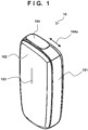
- Fig. 1 is a perspective view showing the outer appearance of an aerosol generating device 10 according to an embodiment.
- Fig. 2 is an explanatory diagram for explaining the insertion of a tobacco stick into the aerosol generating device 10 shown in Fig. 1 .
- the aerosol generating device 10 includes a main body 101, a front panel 102, a display window 103, and a slider 104.
- the main body 101 is a housing internally supporting one or more circuit boards of the aerosol generating device 10.
- the main body 101 has a substantially cuboidal rounded shape elongated in the vertical direction of the drawing.
- the size of the main body 101 can be a size which the user can grasp with one hand.
- the front panel 102 is a flexible panel member covering the front surface of the main body 101.
- the front panel 102 can be detachable from the main body 101.
- the front panel 102 also functions as an input unit for accepting a user input. For example, when the user pushes the center of the front panel 102, a button (not shown) disposed between the main body 101 and the front panel 102 is pressed, so a user input can be detected.
- the display window 103 is a band-like window extending along the longitudinal direction in substantially the center of the front panel 102.
- the display window 103 transmits light generated by one or more light emitting diodes (LEDs) arranged between the main body 101 and the front panel 102 to the outside.
- LEDs light emitting diodes
- the slider 104 is a cover member slidably disposed along a direction 104a on the upper surface of the main body 101. As shown in Fig. 2 , when the slider 104 is slid to the near side of the drawing (that is, when the slider 104 is opened), an opening 106 in the upper surface of the main body 101 is exposed. When inhaling aerosol by using the aerosol generating device 10, the user inserts a tobacco stick 15 into a tubular insertion hole 107 along a direction 106a from the opening 106 exposed by opening the slider 104. That is, the insertion hole 107 has a role as a receiving portion for receiving the tobacco stick 15.
- a section perpendicular to the axial direction of the insertion hole 107 can be, for example, circular, elliptical, or polygonal, and the sectional area of the section gradually reduces toward the bottom surface. Accordingly, the inner surface of the insertion hole 107 pushes the outer surface of the tobacco stick 15 inserted into the insertion hole 107, thereby preventing a fall of the tobacco stick 15 by the frictional force. This also increases the efficiency of heat transfer from a heating unit 130 (to be described later) to the tobacco stick 15. When the user finishes inhaling aerosol, he or she pulls out the tobacco stick 15 from the insertion hole 107, and closes the slider 104.
- the tobacco stick 15 is a tobacco article holding a filler inside a cylindrical rolling paper.
- the filler of the tobacco stick 15 can be, for example, a mixture of an aerosol generating substrate and shredded tobacco.
- the aerosol generating substrate it is possible to use a substrate containing an aerosol source of any kind, such as glycerin, propylene glycol, triacetin, 1,3-butanediol, or a mixture thereof.
- the shredded tobacco is a so-called flavor source.
- the material of the shredded tobacco can be, for example, a lamina or a backbone. Note that a flavor source not originating from tobacco may also be used instead of the shredded tobacco.
- the tobacco stick 15 includes an aerosol source (or an aerosol source and a flavor source) by an amount that enables M-time inhalation of aerosol.
- M can be any integer equal to or larger than 2.
- M can be a value within the range of about 10 to 20, which is close to the number of times of inhalation of one general cigarette.
- the aerosol generating device 10 is not limited to the above-described embodiment and is also capable of receiving a tobacco article (for example, a tobacco capsule, cartridge, or reservoir) having a shape that is not a stick.
- the aerosol source included in the tobacco article can be either a solid or a liquid.
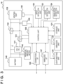
- Fig. 3 is a block diagram showing an example of a general circuit configuration of the aerosol generating device 10.
- the aerosol generating device 10 includes a control unit 120, a storage unit 121, an input detection unit 122, a state detection unit 123, an inhalation detection unit 124, a light emitting unit 125, a vibration unit 126, a communication interface (I/F) 127, a connection I/F 128, a heating unit 130, a first switch 131, a second switch 132, a battery 140, a booster circuit 141, a residual amount meter 142, a measurement circuit 150, and a thermistor 155.
- I/F communication interface
- the control unit 120 can be a processor such as a central processing unit (CPU) or a microcontroller.
- the control unit 120 controls all functions of the aerosol generating device 10 by executing computer programs (also called software or firmware) stored in the storage unit 121.
- the storage unit 121 can be a semiconductor memory or the like.
- the storage unit 121 stores one or more computer programs, and various data (for example, profile data describing a heating profile 50) to be used for heating control (to be described later).
- the input detection unit 122 is a detection circuit for detecting a user input. For example, the input detection unit 122 detects pushing of the front panel 102 (that is, pressing of a button) by the user, and outputs an input signal indicating the detected state to the control unit 120.
- the aerosol generating device 10 can include an input device of any kind such as a button, a switch, or a touch-sensitive screen, instead of (or in addition to) the front panel 102.
- the state detection unit 123 is a detection circuit for detecting an open/closed state of the slider 104. The state detection unit 123 outputs a state detection signal indicating whether the slider 104 is open or closed to the control unit 120.
- the inhalation detection unit 124 is a detection circuit for detecting inhalation (puff) of the tobacco stick 15 by the user.
- the inhalation detection unit 124 can include a thermistor (not shown) disposed near the opening 106. In this case, the inhalation detection unit 124 can detect inhalation by the user based on a change in resistance value of the thermistor resulting from a temperature change caused by the inhalation.
- the inhalation detection unit 124 can include a pressure sensor (not shown) disposed on the bottom of the insertion hole 107. In this case, the inhalation detection unit 124 can detect inhalation based on a reduction in atmospheric pressure resulting from an air current caused by the inhalation.
- the inhalation detection unit 124 outputs, for example, an inhalation detection signal indicating whether inhalation is performed, to the control unit 120.
- the light emitting unit 125 includes one or more LEDs, and a driver for driving the LEDs.
- the light emitting unit 125 turns on each LED in accordance with an instruction signal input from the control unit 120.
- the vibration unit 126 includes a vibrator (e.g., an eccentric motor) and a driver for driving the vibrator.
- the vibration unit 126 vibrates the vibrator in accordance with an instruction signal input from the control unit 120.
- the control unit 120 can use one or both of the light emitting unit 125 and the vibration unit 126 by any pattern, in order to notify the user of a certain status (for example, the progress of a session) of the aerosol generating device 10.
- the light emission patterns of the light emitting unit 125 can be distinguished by elements such as the light emission state (always on/blinking/off), the blinking period, and the light color of each LED.
- the vibration patterns of the vibration unit 126 can be distinguished by elements such as the vibration state (vibration/stop) and the vibration strength of the vibrator.
- the wireless I/F 127 is a communication interface by which the aerosol generating device 10 wirelessly communicates with another device (for example, a personal computer (PC) or a smartphone owned by the user).
- the wireless I/F 127 can be an interface complying with a wireless communication protocol such as Bluetooth ® , near field communication (NFC), or a wireless local area network (LAN).
- the connection I/F 128 is a wired interface having a terminal for connecting the aerosol generating device 10 to another device.
- the connection I/F 128 can be a universal serial bus (USB) interface or the like.
- the connection I/F 128 can also be used to charge the battery 140 from an external power supply (via a feeder line (not shown)).
- the heating unit 130 is a resistive heat generating part that generates aerosol by heating an aerosol source included in an aerosol generating substrate of the tobacco stick 15.
- a resistive heat generating material of the heating unit 130 it is possible to use a mixture of one of more of copper, a nickel alloy, a chromium alloy, stainless steel, and platinum rhodium.
- One terminal of the heating unit 130 is connected to the positive electrode of the battery 140 via the first switch 131 and the booster circuit 141, and the other terminal of the heating unit 130 is connected to the negative electrode of the battery 140 via the second switch 132.
- the first switch 131 is a switching element disposed in a feeder line between the heating unit 130 and the booster circuit 141.
- the second switch 132 is a switching element disposed in a ground line between the heating unit 130 and the battery 140.
- the first switch 131 and the second switch 132 can be, for example, field effect transistors (FETs).
- the battery 140 is a power supply for supplying electric power to the heating unit 130 and other constituent elements of the aerosol generating device 10. Fig. 3 does not show feeder lines from the battery 140 to the constituent elements except the heating unit 130.
- the battery 140 can be, for example, a lithium-ion battery.
- the booster circuit (DC/DC converter) 141 is a voltage conversion circuit for amplifying the voltage of the battery 140 in order to feed the heating unit 130.
- the residual amount meter 142 is an IC chip for monitoring the residual power amount and other statuses of the battery 140. The residual amount meter 142 can periodically measure the status values of the battery 140, such as the state of charge (SOC), the state of health (SOH), the relative SOC (RSOC), and the power supply voltage, and can output the measurement results to the control unit 120.
- SOC state of charge
- SOH state of health
- RSOC relative SOC
- the control unit 120 starts to cause electric power to be supplied from the battery 140 to the heating unit 130.
- This user input can be, for example, long press of a button to be detected by the input detection unit 122.
- the control unit 120 can cause electric power to be supplied from the battery 140 to the heating unit 130 at a voltage amplified by the booster circuit 141 by outputting control signals to the first switch 131 and the second switch 132 to turn on the two switches.
- the control signals to be output from the control unit 120 to the two switches are control pulses to be applied to the gates of these switches.
- the control unit 120 adjusts the duty ratio of these control pulses by pulse width modulation (PWM).
- PWM pulse width modulation
- the control unit 120 can also use pulse frequency modulation (PFM) instead of PWM.
- the control unit 120 controls the supply of electric power from the battery 140 to the heating unit 130 so as to implement a desired temperature profile for providing a good user experience throughout the whole heating period including a preheating period and an inhalable period.
- This control can mainly be feedback control using a temperature index having a correlation with the temperature of the heating unit 130 as a controlled variable, and the duty ratio of PWM as a manipulated variable. Assume that PID control is adopted as this feedback control.
- the aerosol generating device 10 has two types of measurement units for measuring the temperature index of the heating unit 130.
- the measurement circuit 150 shown in Fig. 3 is one of the two types of measurement units, and the thermistor 155 is the other one.
- the measurement circuit 150 is used to measure a first temperature index based on the electrical resistance value of the heating unit 130.
- the thermistor 155 is used to measure a second temperature index depending on the temperature of the heating unit 130 in a period (an OFF period to be described later) during which no voltage is applicable to the heating unit 130.
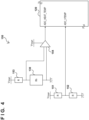
- Fig. 4 is a block diagram showing an example of the configuration of the measurement circuit 150 shown in Fig. 3 .
- the measurement circuit 150 includes divider resistors 151, 152, and 153, and an operational amplifier 154.
- One terminal of the divider resistor 151 is connected to a power supply voltage V TEMP , and the other terminal is connected to one terminal of the divider resistor 152.
- the other terminal of the divider resistor 152 is grounded.
- the contact between the divider resistor 151 and the divider resistor 152 is connected to a terminal ADC_VTEMP of the control unit 120.
- An input to the terminal ADC_VTEMP indicates a reference value for resistance value measurement.
- One terminal of the divider resistor 153 is connected to the power supply voltage V TEMP , and the other terminal is connected to the feeder line of the heating unit 130.
- the contact between the divider resistor 153 and the feeder line of the heating unit 130 is connected to a first input terminal of the operational amplifier 154.
- a second input terminal of the operational amplifier 154 is grounded.
- An output terminal of the operational amplifier 154 is connected to a terminal ADC_HEAT_TEMP of the control unit 120.
- An input to the terminal ADC_HEAT_TEMP indicates a value that changes due to an electrical resistance value Rh depending on the temperature of the heating unit 130.
- the control unit 120 can calculate the electrical resistance value Rh of the heating unit 130 based on the ratio of the value input to the terminal ADC_HEAT_TEMP to the value (reference value) input to the terminal ADC_VTEMP.
- the electrical resistance value of the heating unit 130 has, for example, the characteristic that the value monotonously increases as the temperature rises (that is, the value has a correlation to the temperature).
- the control unit 120 uses the electrical resistance value of the heating unit 130, which is calculated by using the measurement circuit 150, as a temperature index (the first temperature index) as the controlled variable of PID control.
- H TGT [°C] be the target temperature of PID control at a certain point of time
- the target temperature can be converted into a target temperature resistance value R TGT [ ⁇ ]:
- R TGT H TGT ⁇ H ENV ⁇ ⁇ ⁇ R ENV + R ENV
- H ENV represents a reference environmental temperature
- ⁇ represents the temperature-resistance coefficient of the resistive heat generating material of the heating unit 130
- R ENV represents an electrical resistance value at the reference environmental temperature.
- the values of H ENV , ⁇ , and R ENV are measured or derived by an evaluation test in advance and prestored in the storage unit 121.
- control unit 120 may, of course, further convert the electrical resistance value of the heating unit 130 into a temperature by using a resistance-temperature coefficient, and use the derived measured temperature as the controlled variable of PID control.
- temperature control of the heating unit 130 is mainly performed by the method of deciding the duty ratio of PWM of electric power to be supplied to the heating unit 130.
- R TGT [ ⁇ ] be the target value (the resistance value corresponding to the target temperature) of PID control
- R(n) [ ⁇ ] be the value (measured resistance value) of the first temperature index in a current control cycle n (n is an integer)
- a duty ratio D(n) of the control cycle n can be derived in accordance with, for example, equation (2) below:
- D n K p ⁇ R TGT ⁇ R n + K i ⁇ ⁇ 0 n
- K p , K i , and K d respectively represent a proportional gain, an integral gain, and a differential gain.
- saturation control can be applied to a cumulative value of a deviation of the index value with respect to the target value. In this case, if the cumulative value is larger than a predetermined upper limit value, the cumulative value is substituted by the upper limit value; and if the cumulative value is smaller than a predetermined lower limit value, the cumulative value is substituted by the lower limit value.
- the control unit 120 sets a part of repetitive control cycles as a measurement period for measuring the first temperature index, and sets the remainder of the control cycles as a PWM control period for performing PWM control.
- Fig. 5 is an explanatory diagram for explaining the measurement period and the PWM control period during the heating period.
- the abscissa represents the time
- the ordinate represents the voltage to be applied to the heating unit 130.
- One control cycle during the heating period includes a measurement period 20 at the beginning and a PWM control period 30 as the remainder. In this example shown in Fig.
- a period from t0 to t1 is the measurement period 20 of one control cycle
- a period from t1 to t2 is the PWM control period 30 of the same control cycle
- a period from t2 to t3 is the measurement period 20 of the next one control cycle
- a period from t3 to t4 is the PWM control period 30 of the same control cycle.
- the length of one control cycle is equivalent to the periodicity of measurement of the first temperature index, and can be, for example, tens of milliseconds.
- the control unit 120 applies a very short pulse 21 (for example, the pulse width is 2 ms) to the heating unit 130 a plurality of times (for example, 8 times) during the measurement period 20, and obtains the average value of resistance values calculated a plurality of times by using the measurement circuit 150 during one measurement period 20 as the measured value R(n) of the first temperature index.
- the control unit 120 calculates the duty ratio D(n) of PWM in the control cycle n in accordance with the above-described control equation.
- the control unit 120 applies a pulse 31 having a pulse width W1 equivalent to the product of a length W0 of this period and the duty ratio D(n) to the heating unit 130 (that is, outputs control pulses having the same pulse width W1 to the first switch 131 and the second switch 132).
- the temperature of the heating unit 130 is so controlled as to approach the target value by repeating the feedback control as described above.
- the second temperature index based on the output value from the thermistor 155 is used to determine the temperature of the heating unit 130 in a period during which no pulse is applied to the heating unit 130 for the purpose of, for example, efficiently decreasing the temperature of the heating unit 130, which is once raised to a high value, to a lower value.
- the thermistor 155 is disposed near the heating unit 130, and outputs a value depending on the temperature of the heating unit 130 to the control unit 120.
- the control unit 120 executes temperature control of the heating unit 130 in accordance with the heating profile as a control sequence defining temporal changes in control conditions for implementing a desired temperature profile.
- the heating profile includes a plurality of sections temporally dividing the heating period, and designates specifications of temperature control of each section by a target value and other control parameters.
- Fig. 6 is an explanatory diagram for explaining the temperature profile and the heating profile adoptable in this embodiment.
- the abscissa represents the elapsed time from the start of power supply to the heating unit 130
- the ordinate represents the temperature of the heating unit 130.
- a thick line represents a temperature profile 40 as an example.
- the temperature profile 40 includes a preheating period (T0 to T2) at the beginning, and an inhalable period (T2 to T8) following the preheating period.
- T0 to T2 preheating period
- T2 to T8 an inhalable period
- the whole length of the inhalable period can be about five minutes.
- the preheating period includes a temperature rise section (T0 to T1) in which the temperature of the heating unit 130 is rapidly raised from an environmental temperature H0 to a first temperature H1, and a maintaining section (T1 to T2) in which the temperature of the heating unit 130 is maintained at the first temperature H1.
- the inhalable period includes a maintaining section (T2 to T3) in which the temperature of the heating unit 130 is maintained at the first temperature H1, a temperature fall section (T3 to T4) in which the temperature of the heating unit 130 is lowered to a second temperature H2, and a maintaining section (T4 to T5) in which the temperature of the heating unit 130 is maintained at the second temperature H2. Since the temperature of the heating unit 130, which is once raised to the first temperature H1, is lowered to the second temperature H2 as described above, it is possible to stably provide the user with inhalation with a good tobacco flavor for a longer time.
- the inhalable period further includes a temperature rise section (T5 to T6) in which the temperature of the heating unit 130 is gradually raised from the second temperature H2 to a third temperature H3, a maintaining section (T6 to T7) in which the temperature of the heating unit 130 is maintained at the third temperature H3, and a temperature fall section (T7 to T8) in which the temperature of the heating unit 130 is lowered to the environmental temperature H0. Since the temperature of the heating unit 130 is again raised in the second half of the inhalable period as described above, it is possible to suppress a decrease in tobacco flavor in a situation in which the amount of the aerosol source included in the tobacco stick 15 decreases, and provide the user with a highly satisfactory experience to the end of the inhalable period.
- the first temperature H1, the second temperature H2, and the third temperature H3 can be 295°C, 230°C, and 260°C, respectively.
- the heating profile 50 includes eight sections S0 to S7 bounded by T1 to T7. As will be explained later, however, the transition timing between two sections does not necessarily match one of the points in time T1 to T7 shown in the drawing, but follows a termination condition of each section. In the next clause, a more specific configuration example of the heating profile 50 will be explained in order for individual sections.
- the section S0 is the first-half section of the preheating period.
- PID control is performed by setting the target value of temperature control at a resistance value (to be referred to as R1 hereinafter) corresponding to the first temperature H1.
- the proportional gain of PID control in the section S0 is set at a value higher than those in other sections, so the time required to raise the temperature can be shortened as much as possible.
- the section S0 ends when the first temperature index has reached the resistance value R1.
- the section S1 is the second-half section of the preheating period.
- PID control is performed by setting the target value of temperature control at the resistance value R1.
- the proportional gain of PID control in the section S1 can be set at a value that stabilizes the temperature of the heating unit 130 near the first temperature H1 (for example, this proportional gain can be set at a value smaller than the proportional gain designated for the section S0).
- the section S1 ends when a time length that can be set at a value within the range of, for example, a few seconds has elapsed. When the section S1 ends, the control unit 120 notifies the user of the end of the preheating period.
- This notification can be performed by one or both of light emission of the light emitting unit 125 by a predetermined light emission pattern and the vibration of the vibration unit 126 by a predetermined vibration pattern. Upon sensing this notification, the user recognizes that preparations of inhalation are complete and inhalation can be started.
- the section S2 is a section at the beginning of the inhalable period.
- PID control is performed by setting the target value of temperature control at the resistance value R1.
- the gains of PID control in the section S1 can be the same as those of the section S1
- the section S2 ends when a time length that can be set at a value within the range of, for example, a few seconds to about ten seconds has elapsed.
- the user can start inhaling aerosol generated by the aerosol generating device 10 from the section S2.
- the control unit 120 Based on an inhalation detection signal input from the inhalation detection unit 124, the control unit 120 measures inhalation-related statistics, such as the inhalation detection count, the inhalation detection frequency, or the cumulative inhalation time, and stores the measurement results in the storage unit 121. This measurement can also be performed continuously from the section S3 as well.
- the section S3 is a section for decreasing the temperature of the heating unit 130, which has once risen to the first temperature H1.
- the control unit 120 stops causing electric power to be supplied from the battery 140 to the heating unit 130, so that the temperature of the heating unit 130 falls toward the second temperature H2.
- a section in which no electric power is supplied to the heating unit 130 as described above is called an OFF section.
- the control unit 120 terminates the section S3 if it is determined that, for example, the temperature of the heating unit 130 has reached the second temperature H2, based on the second temperature index based on the output value from the thermistor 155.
- the section S4 is a section for maintaining the temperature of the heating unit 130 near the second temperature H2.
- PID control is performed by setting the target value of temperature control at a resistance value (to be referred to as R2 hereinafter) corresponding to the second temperature H2.
- the gains of PID control in the section S4 can be the same as those of the sections S1 and S2.
- the section S4 is a section in which the user can stably repeat inhalation with a moderate tobacco flavor, and which continues over a time length (for example, tens of seconds to a few minutes) longer than those of the sections S2 and S3. If inhalation is performed at a fast pace in the section S4, the aerosol source included in the tobacco stick 15 may reduce earlier.
- control unit 120 monitors the inhalation-related statistics in at least the section S4 (or in sections after the section S2).
- this statistics to be monitored is also simply referred to as control parameter(s).
- the control parameter(s) herein can be the inhalation detection count, the inhalation detection frequency, or the cumulative inhalation time.
- the control unit 120 causes temperature control to transition from the section S4 to the section S5.
- the predetermined condition herein will be explained below by taking several examples. Even if the control parameter does not meet the predetermined condition, the control unit 120 causes temperature control to transition from the section S4 to the section S5 when a predetermined time has elapsed from the reference point in time.
- the reference point in time may be the starting point in time (T4 in Fig. 6 ) of the section S4.
- the reference point in time may be the point in time (T2 in Fig. 6 ) at which the user is notified of the termination of preheating.
- the section S5 is a section for raising the temperature of the heating unit 130 from the second temperature H2 to the third temperature H3.
- PID control is performed in the section S5, and its target value is almost linearly increased, actually, increased step by step in each control cycle, so that the temperature of the heating unit 130 gradually rises to the third temperature H3 from the start to the end of the section.
- the gains of PID control in the section S5 can be the same as or different from those of the section S4. As shown in Fig. 6 , if the transition from the section S4 to the section S5 is performed at T5, the section S5 ends at T6. If the transition from the section S4 to the section S5 is performed earlier, the ending point in time of the section S5 may be different in various embodiments to be described later.
- the temperature rise rate of the heating unit 130 in the section S5 is equal to the gradient of the target value of PID control as long as stable control continues.
- the gradient of the target value may be predefined as an amount of change in the target value in each control cycle, or may be derived by dividing the difference between the measured temperature at the start of the section and the target value at the end of the section by the time length of the section S5.
- the section S5 ends when the temperature of the heating unit 130 has reached the third temperature H3.
- the section S6 is a section for maintaining the temperature of the heating unit 130 near the third temperature H3.
- PID control is performed by setting the target value of temperature control at a resistance value (to be referred to as R3 hereinafter) corresponding to the third temperature H3.
- the gains of PID control in the section S6 can be the same as those of the sections S 1, S2, and S4.
- the section S6 ends when a time length that can be set at a value within the range of, for example, tens of seconds has elapsed.
- the section S7 is a section at the end of the heating period.
- the control unit 120 stops the supply of electric power from the battery 140 to the heating unit 130, so that the temperature of the heating unit 130 falls toward the environmental temperature H0. That is, the section S7 is an OFF section.
- the section S7 ends when a time length that can be set at a value within the range of, for example, a few seconds to tens of seconds has elapsed.
- the control unit 120 may notify the user of an approach of the end of the inhalable period, by the light emission of the light emitting unit 125 or the vibration of the vibration unit 126.
- the control unit 120 may also notify the user of the end of the inhalable period at the end of the section S7, by the light emission of the light emitting unit 125 or the vibration of the vibration unit 126.
- the section S4 which is a temperature-maintaining section after the temperature has fallen to the second temperature H2, ends at the point in time (T5 in Fig. 6 ) at which a predetermined time has elapsed from the reference point in time at the latest, and temperature control transitions to the section S5 as a temperature rerise section.
- this transition timing becomes earlier if the statistics related to inhalation by the user meets a predetermined condition.
- a case in which the transition from the section S4 to the section S5 is performed when a predetermined time has elapsed from the reference point in time is called "normal transition”
- a case in which this transition is performed earlier is called "early transition”.
- the behavior of temperature control during and after the section S5 are made different between the normal transition and the early transition so as to further improve quality of the user's inhalation experience. For example, if the statistics indicates that the pace of inhalation by the user is fast, the temperature of the heating unit 130 is made to reach the third temperature H3 at an early timing suitable for the pace. This allows the user to really feel the improvement of the tobacco flavor brought about by temperature rerise. If the pace of inhalation by the user is slow, the temperature of the heating unit 130 is made to reach the third temperature H3 by taking the designed time. This can provide the user with the inhalation experience for a longer time. In this clause, several embodiments for implementing different temperature profiles depending on the inhalation-related statistics as described above will be explained.
- the statistics related to inhalation by the user can be, for example, the inhalation detection count, the inhalation detection frequency, or the cumulative inhalation time.
- the condition of early transition can include the inhalation detection count reaching a first transition threshold.
- the first transition threshold may be set as a value equal to or larger than M/2. This means that the half of the aerosol source contained in the tobacco stick 15 is already consumed when the inhalation detection count reaches the first transition threshold. In this case, it is possible to reduce a possibility that an improvement of the tobacco flavor brought about by temperature rerise misses the opportunity, by performing temperature rerise in the section S5 more quickly than in the case of normal transition.
- the first transition threshold can be set at M - 1 if M > 3. This means that, when the inhalation detection count has reached the first transition threshold, the aerosol source contained in the tobacco stick runs out if the user performs inhalation once more.
- the temperature of the heating unit 130 it is possible to make the temperature of the heating unit 130 as high as possible when the user performs the last inhalation, and surely allows the user to enjoy a satisfactory tobacco flavor at the end of the session.
- the condition of early transition can include a condition that the inhalation detection frequency exceeds a second transition threshold.
- the inhalation detection frequency is obtained by dividing the inhalation detection count by the length of the monitoring period. Note that at the beginning of a section, the denominator of a frequency calculation is smaller and the value of a control parameter is unstable, so a section transition in this case may not be performed until a certain time elapses from the start of the section.
- the second transition threshold may be set at, for example, a value with which the inhalation detection count would reach the upper limit before the arrival of T6 if inhalation is continued at that frequency.
- the condition of early transition can include the cumulative inhalation time reaching a third transition threshold.
- the amount of the aerosol source contained in the tobacco stick 15 is an amount that is consumed by inhalation over a total time L by assuming an average inhalation strength.
- the third transition threshold may be set as a value larger than L/2. This means that the half of the aerosol source contained in the tobacco stick 15 is already consumed when the cumulative inhalation time reaches the third transition threshold.
- a possibility that the improvement of a tobacco flavor brought about by temperature rerise misses the opportunity can be reduced by performing temperature rerise in the section S5 more rapidly than in the case of normal transition.
- the control unit 120 measures the inhalation detection count from the point in time (T2 in Fig. 6 ) at which the user is notified of the termination of preheating or the point in time (T4 in Fig. 6 ) at which the section S4 starts, and monitors this count as a control parameter.
- T2 in Fig. 6 the point in time
- T4 in Fig. 6 the point in time
- Fig. 7 shows a temperature profile 41 as an example that can be implemented in the first embodiment, in comparison with the temperature profile 40 in normal transition shown in Fig. 6 .
- T puff represents the time at which it is determined that the inhalation detection count has met the abovementioned predetermined condition, and is earlier than T5 at which the maximum time length set for the section S4 elapses.
- the control unit 120 determines at T puff that the inhalation detection count has met the abovementioned predetermined condition, the control unit 120 immediately causes temperature control to transition to the section S5.
- the control unit 120 performs temperature control of the section S5 such that the temperature of the heating unit 130 reaches the third temperature H3 at T5a earlier than T6 at which the temperature of the heating unit 130 would reach the third temperature H3 in normal transition.
- the time length from T puff to T5a is equal to the time length from T5 to T6, so the gradient of the target value of PID control in the section S5 is the same in these two cases of normal transition and early transition.
- Fig. 8 shows a temperature profile 42 as an example that can be implemented in the second embodiment, in comparison with the temperature profile 40 in normal transition shown in Fig. 6 .
- the control unit 120 determines at T puff that the inhalation detection count has met the abovementioned predetermined condition, the control unit 120 immediately causes temperature control to transition to the section S5.
- the control unit 120 performs temperature control of the section S5 such that the temperature of the heating unit 130 reaches the third temperature H3 at T5b earlier than T6 at which the temperature of the heating unit 130 would reach the third temperature H3 in normal transition.
- the time length from T puff to T5b is shorter than the time length from T5 to T6.
- the gradient of the target value of PID control in the section S5 in this early transition case is steeper than in the normal transition case, and this means that the temperature rise rate of the heating unit 130 is higher.
- the target temperature reaches the third temperature H3 within a time shorter than that in the first embodiment, so it is possible to secure a sufficient time during which the user can enjoy a high-quality inhalation experience in a state in which temperature rerise has been completed.
- Fig. 9 shows a temperature profile 43 as an example that can be implemented in the third embodiment, in comparison with the temperature profile 40 in normal transition shown in Fig. 6 .
- the control unit 120 determines at T puff that the inhalation detection count has met the abovementioned predetermined condition, the control unit 120 immediately causes temperature control to transition to the section S5.
- the control unit 120 performs temperature control of the section S5 such that the temperature of the heating unit 130 reaches the third temperature H3 at T5c earlier than T6 at which the temperature of the heating unit 130 would reach the third temperature H3 in normal transition.
- the time length from T puff to T5c is longer than the time length from T5 to T6.
- the gradient of the target value of PID control in the section S5 in this early transition case is gentler than that in the normal transition case, and this means that the temperature rise rate of the heating unit 130 is lower.
- the load applied to the battery 140 at the time of temperature rerise is suppressed compared to the first and second embodiments, so it is possible to minimize a possibility that an operation failure occurs due to a drop voltage (a temporary voltage drop while electric power is output).
- Fig. 10 shows a temperature profile 44 as an example that can be implemented in the fourth embodiment, in comparison with the temperature profile 40 in normal transition shown in Fig. 6 .
- the delay time dT is shorter than the residual time from T puff to T5.
- the control unit 120 performs temperature control of the section S5 such that the temperature of the heating unit 130 reaches the third temperature H3 at T5d earlier than T6 at which the temperature of the heating unit 130 would reach the third temperature H3 in normal transition.
- the time length from T puff to T5d is equal to the time length from T5 to T6, so the gradient of the target value of PID control in the section S5 is the same in these two cases of normal transition and early transition.
- the same setting as that in the normal transition case can be used in the earlier transition case, without setting another temperature rise rate and retuning the gain.
- setting the delay time as described above instead of immediately triggering transition of temperature control can contribute to optimization of the user's inhalation experience as well.
- Fig. 11 shows a temperature profile 45 as an example that can be implemented in the fifth embodiment, in comparison with the temperature profile 40 in normal transition shown in Fig. 6 .
- the control unit 120 performs temperature control of the section S5 such that the temperature of the heating unit 130 reaches the third temperature H3 at T5e earlier than T6 at which the temperature of the heating unit 130 would reach the third temperature H3 in normal transition.
- the time length from T puff to T5e is shorter than the time length from T5 to T6. Therefore, the gradient of the target value of PID control in the section S5 in this early transition case is steeper than that in the normal transition case, and this means that the temperature rise rate of the heating unit 130 is higher.
- the target temperature reaches the third temperature H3 within a time shorter than that in the fourth embodiment, so it is possible to secure a sufficient time during which the user can enjoy a high-quality inhalation experience in a state in which temperature rerise has been completed.
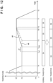
- Fig. 12 shows a temperature profile 46 as an example that can be implemented in the sixth embodiment, in comparison with the temperature profile 40 in normal transition shown in Fig. 6 .
- the control unit 120 performs temperature control of the section S5 such that the temperature of the heating unit 130 reaches the third temperature H3 at T5f earlier than T6 at which the temperature of the heating unit 130 would reach the third temperature H3 in normal transition.
- the time length from T trans to T5f is longer than the time length from T5 to T6. Therefore, the gradient of the target value of PID control in the section S5 in this early transition case is gentler than that in the normal transition case, and this means that the temperature rise rate of the heating unit 130 is lower. According to the sixth embodiment, the load applied to the battery 140 at the time of temperature rerise is suppressed compared to the fourth and fifth embodiments, so it is possible to minimize a possibility that an operation failure occurs due to the drop voltage.
- Fig. 13 shows a temperature profile 47 as an example that can be implemented in the seventh embodiment, in comparison with the temperature profile 40 in normal transition shown in Fig. 6 .
- the control unit 120 determines at T puff that the inhalation detection count has met the abovementioned predetermined condition, the control unit 120 waits until T5, instead of immediately causing temperature control to transition to the section S5, and then causes temperature control to transition to the section S5.
- the control unit 120 performs temperature control in the section S5 such that the temperature of the heating unit 130 reaches the third temperature H3 at T5g earlier than T6 at which the temperature of the heating unit 130 would reach the third temperature H3 in normal transition.
- the seventh embodiment does not match the above-described definition of early transition because the transition timing from the section S4 to the section S5 is equal to T5 regardless of whether the abovementioned predetermined condition is met.
- the seventh embodiment is also treated as early transition in a sense that the timing at which the temperature of the heating unit 130 reaches the third temperature H3 is advanced and the transition to the section S6 becomes earlier.
- the time length from T5 to T5g is shorter than the time length from T5 to T6. Therefore, the gradient of the target value of PID control in the section S5 in this early transition case is steeper than that in the normal transition case, and this means that the temperature rise rate of the heating unit 130 is higher.
- the target temperature can reach the third temperature H3 within a time shorter than that in the normal transition case.
- Figs. 7 to 13 show examples in which the section S6 ends at T7 in the same manner as in normal transition even in early transition. In each of the first to seventh embodiments, however, the control unit 120 may terminate the section S6, which occurs after early transition, at a point in time earlier than a point in time at which the section S6 would end after normal transition.
- Fig. 14 shows a temperature profile 48 as an example according to the eighth embodiment as described above.
- the control unit 120 determines at T puff that the inhalation detection count has met the abovementioned predetermined condition, the control unit 120 immediately causes temperature control to transition to the section S5, and performs temperature control of the section S5 such that the temperature of the heating unit 130 reaches the third temperature H3 at T5a earlier than T6 in the same manner as in the first embodiment. Then, the control unit 120 performs temperature control (that is, temperature-maintaining after temperature rerise) of the section S6 from T5a to T7a, causes temperature control to transition to the section S7 at T7a, and stops the supply of electric power from the battery 140 to the heating unit 130.
- T7a is earlier than T7 as the point in time at which the supply of electric power to the heating unit 130 would be stopped in the case of normal transition. As T7a becomes earlier, the total electric power that is consumed in one session is reduced.
- the control unit 120 may determine the timing T7a to stop the supply of electric power to the heating unit 130 depending on the value of a control parameter being monitored. For example, if the inhalation detection count has reached an upper-limiting value M, the control unit 120 may terminate the section S6 and stop the supply of electric power to the heating unit 130. Alternatively, if the cumulative inhalation time has reached an upper-limiting value L, the control unit 120 may terminate the section S6 and stop the supply of electric power to the heating unit 130. This can avoid the waste of electric power in a situation in which only a slight amount of the aerosol source remains in the tobacco stick 15.
- the control unit 120 may selectively apply control behavior, which differs depending on the inhalation-related statistics measured until T puff , to temperature control of the section S5. For example, if an inhalation detection frequency higher than (or a cumulative inhalation time longer than) a certain threshold is measured, the control unit 120 may apply a high temperature rise rate like that in the second embodiment to temperature control of the section S5.
- the control unit 120 may apply a normal temperature rise rate like that in the first embodiment to temperature control of the section S5. As another example, if an inhalation detection frequency higher than (or a cumulative inhalation time longer than) a certain threshold is measured, the control unit 120 may immediately cause temperature control to transition to the section S5 as in the first, second, or third embodiment. On the other hand, if an inhalation detection frequency lower than (or a cumulative inhalation time shorter than) the certain threshold is measured, the control unit 120 may wait for the delay time dT and then cause temperature control to transition to the section S5 as in the fourth, fifth, or sixth embodiment.
- the control unit 120 may change the delay time dT depending on the length of the residual time from T puff to T5. For example, the control unit 120 may set the delay time dT to the product of the residual time from T puff to T5 and a predetermined ratio ⁇ (0 ⁇ ⁇ ⁇ 1), and cause temperature control to transition to the section S5 after having waited for the delay time dT. This enables the transition timing of temperature control to be more flexibly adjusted.
- the control unit 120 may control the temperature rise rate of the heating unit 130 by increasing or decreasing a gain while keeping the target value of PID control constant in the section S5.
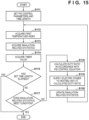
- Fig. 15 is a flowchart showing the first example of the flow of the temperature control process that can be executed in the section S4 as a temperature-maintaining section after temperature fall.
- the first example may correspond to the first, second, third, or eighth embodiment described above.
- the control unit 120 sets PID control parameters and the time length of the current section in accordance with the heating profile 50.
- the PID control parameter set in this step can include, for example, a target temperature resistance value, a proportional gain, an integral gain, and a differential gain.
- the control unit 120 acquires the first temperature index based on the electrical resistance value of the heating unit 130 by using the measurement circuit 150.
- the index value acquired herein may be, for example, an average value as a result of a plurality of times of resistance value measurement as explained with reference to Fig. 5 .
- the control unit 120 acquires the latest value of the inhalation-related statistics (for example, the inhalation detection count).
- the control unit 120 acquires the value of the timer activated at the start of the section S2 or the section S4.
- the control unit 120 determines whether the time length set in S111 has elapsed, based on the timer value acquired in S114. If the set time length has not elapsed yet, the process advances to S117. In S117, the control unit 120 determines whether the inhalation-related statistics acquired in S113 meets the above-described predetermined condition. If the inhalation-related statistics does not meet the predetermined condition, the temperature control process in the section S4 is continued, and the process advances to S118.
- control unit 120 calculates the duty ratio of PWM for the latest control cycle in accordance with the PID control equation explained by using equation (2). Then, in S119, the control unit 120 outputs control pulses having a pulse width based on the calculated duty ratio to the first switch 131 and the second switch 132, thereby causing electric power to be supplied from the battery 140 to the heating unit 130. Then, in S120, the control unit 120 updates the inhalation-related statistics that is subject to monitoring, based on an inhalation detection signal input from the inhalation detection unit 124.
- control unit 120 determines in S115 that the set time length has elapsed, or determines in S117 that the inhalation-related statistics meets the predetermined condition, the control unit 120 terminates the temperature control process in the section S4 shown in Fig. 15 , and causes temperature control to transition to the section S5.
- Fig. 16 is a flowchart showing the second example of the flow of the temperature control process that can be executed in the section S4 as a temperature-maintaining section after temperature fall.
- the second example may correspond to the fourth, fifth, sixth, or seventh embodiment described above.
- the control unit 120 sets PID control parameters and the time length of the current section in accordance with the heating profile 50.
- the PID control parameter set in this step can include, for example, a target temperature resistance value, a proportional gain, an integral gain, and a differential gain.
- control unit 120 acquires the first temperature index based on the electrical resistance value of the heating unit 130 by using the measurement circuit 150. Also, in S113, the control unit 120 acquires the latest value of the inhalation-related statistics. In S114, the control unit 120 acquires the value of the timer activated at the start of the section S2 or the section S4.
- the control unit 120 determines whether the time length set in S111 has elapsed, based on the timer value acquired in S114. If the set time length has not elapsed yet, the process advances to S116. In S116, the control unit 120 determines whether the state of temperature control at the moment is a transition waiting state (that is, in the middle of the delay time dT). At the beginning of the section S4, the control state is not the transition waiting state, so the process advances to S117. In S117, the control unit 120 determines whether the inhalation-related statistics acquired in S113 meets the above-described predetermined condition. If the inhalation-related statistics meets the predetermined condition, temperature control enters the transition waiting state in S121. If the inhalation-related statistics does not meet the predetermined condition, S121 is skipped.
- control unit 120 calculates the duty ratio of PWM for the latest control cycle in accordance with the PID control equation explained by using equation (2), regardless of whether the current state is the transition waiting state. Then, in S119, the control unit 120 outputs control pulses having a pulse width based on the calculated duty ratio to the first switch 131 and the second switch 132, thereby causing electric power to be supplied from the battery 140 to the heating unit 130. Then, in S120, the control unit 120 updates the inhalation-related statistics that is subject to monitoring, based on an inhalation detection signal input from the inhalation detection unit 124.
- the process advances to the next control cycle, and S112 to S120 described above are repeated. If the control unit 120 determines in S115 that the set time length has elapsed, the control unit 120 terminates the temperature control process of the section S4 shown in Fig. 15 , and causes temperature control to transition to the section S5. Meanwhile, if the control unit 120 determines in S116 that the state of temperature control at the moment is the transition waiting state, the control unit 120 further determines in S122 whether the delay time dT has elapsed. If the control unit 120 determines that the delay time dT has elapsed, the control unit 120 terminates the temperature control process of the section S4, and causes temperature control to transition to the section S5. On the other hand, if it is determined in S122 that the delay time dT has not elapsed yet, the process advances to S118, and the temperature control process of the section S4 is continued.
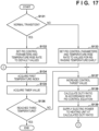
- Fig. 17 is a flowchart showing an example of the flow of the temperature control process that can be executed in the section S5 as a temperature rerise section.
- the temperature control process of the section S5 branches depending on whether transition from the section S4 to the section S5 has been normal transition or early transition. If the transition from the section S4 to the section S5 has been normal transition, the process advances to S132. On the other hand, if the transition from the section S4 to the section S5 has been early transition, the process advances to S133.
- control unit 120 sets the PID control parameters and the temperature rise rate (an amount of change in the target value in each control cycle) of the current section to default values in accordance with the heating profile 50.
- control unit 120 sets the PID control parameters and the temperature rise rate of the current section to values for causing the temperature of the heating unit 130 to reach the third temperature H3 earlier than in the case of normal transition.
- control unit 120 acquires the first temperature index based on the electrical resistance value of the heating unit 130 by using the measurement circuit 150. Also, in S135, the control unit 120 acquires the value of the timer activated at the start of the section S5.
- the control unit 120 determines whether the target value of temperature control increased in each control cycle has reached the third temperature. If it is determined that the target value of PID control has not reached the third temperature, the process advances to S137. Note that this determination in S136 may be replaced by determination of whether the timer value has reached the time length of the section S5 (that may be different between normal transition and early transition). In S137, the control unit 120 increases the target value of PID control in accordance with the temperature rise rate set in S132 or S133.
- control unit 120 calculates the duty ratio of PWM for the latest control cycle in accordance with the PID control equation explained by using equation (2). Then, in S139, the control unit 120 outputs control pulses having a pulse width based on the calculated duty ratio to the first switch 131 and the second switch 132, thereby causing electric power to be supplied from the battery 140 to the heating unit 130.
- control unit 120 determines in S136 that the target value of PID control has reached the third temperature H3, the control unit 120 terminates the temperature control process of the section S5 shown in Fig. 17 , and causes temperature control to transition to the section S6.
Landscapes
- Control Of Resistance Heating (AREA)
Abstract
Description
- This disclosure relates to an aerosol generating device and a control method.
- An electric heating type aerosol generating device that generates aerosol by heating an aerosol source and delivers the generated aerosol to a user is known. For example, an electronic cigarette is a kind of the above-described aerosol generating device. The electronic cigarette imparts a flavor component to generated aerosol to let the user inhale the aerosol.
- The amount of aerosol per unit time generated from the aerosol source varies depending on a temperature at which a substrate containing the aerosol source is heated, in addition to the properties and shape of the substrate. Therefore, the aerosol generating device controls the heating temperature so that the amount of aerosol to be supplied to the user becomes a desired amount. Generally, data expressing a temporal change of the temperature is called a temperature profile, and data chronologically defining the specification of temperature control for implementing the desired temperature profile is called a heating profile.
- For example,
PTL 1 discloses a temperature profile that raises the temperature of a heating element to a given high value in the first stage, lowers the temperature of the heating element to a lower value in the subsequent second stage, and gradually raises the temperature of the heating element in the subsequent third stage. This temperature profile temporally flattens the aerosol generation amount to some extent. In relation to this temperature profile,PTL 1 also discloses determining a timing to cause temperature control to transition from a certain stage to a next stage by using an index such as the elapsed time, the temperature of a heating element, the amount of electric power supplied to the heating element, or the number of times of inhalation. - PTL 1:
Japanese Patent Laid-Open No. 2020-74797 - However, regardless of the type of an index to be used, there are limitations in improving the quality of a user's inhalation experience by only advancing or delaying the transition timing of temperature control. For example, if temperature control is caused to transition early because the pace of inhalation by the user is fast, the behavior of temperature control suitable for a stage after the transition should be different from that of a normal transition.
- The technology according to the present disclosure has been made in consideration of the above situation, and aims at implementing improved temperature control for generating aerosol.
- According to a first aspect, there is provided an aerosol generating device including: a heating unit configured to generate aerosol by heating an aerosol source; a power supply configured to supply electric power to the heating unit; a detection unit configured to detect inhalation of the aerosol by a user; and a control unit configured to control the supply of electric power from the power supply to the heating unit in accordance with a control sequence including at least: a first section in which electric power is supplied from the power supply to the heating unit by setting a target value of temperature control of the heating unit at a value corresponding to a first temperature; a second section which follows the first section and in which electric power is supplied from the power supply to the heating unit by setting the target value of temperature control of the heating unit at a value corresponding to a second temperature lower than the first temperature; and a third section which follows the second section and in which electric power is supplied from the power supply to the heating unit by setting the target value of temperature control of the heating unit at a value corresponding to a third temperature higher than the second temperature, wherein the control unit is configured to: monitor, in at least the second section, a detection count representing the number of times the inhalation is detected by the detection unit, in a case where the detection count does not meet a predetermined condition, cause the temperature control to transition to the third section at a first point in time at which a predetermined time has elapsed from a reference point in time, and perform the temperature control such that a temperature of the heating unit reaches the third temperature at a second point in time after a certain time length has elapsed, and in a case where the detection count has met the predetermined condition, cause the temperature control to transition to the third section at a third point in time, and perform the temperature control such that the temperature of the heating unit reaches the third temperature at a fourth point in time earlier than the second point in time.
- The third point in time may be a point in time earlier than the first point in time.
- The third point in time may be a point in time at which the control unit determines that the detection count has met the predetermined condition.
- The third point in time may be a point in time at which a time shorter than a time remaining until the first point in time has elapsed after the control unit determines that the detection count has met the predetermined condition.
- The third point in time may be equal to the first point in time.
- The control unit may be configured to, in a case of causing the temperature control to transition to the third section as a result of the detection count having met the predetermined condition, perform the temperature control such that a temperature rise rate of the heating unit in the third section becomes higher than that in a case of causing the temperature control to transition to the third section without the detection count meeting the predetermined condition.
- The control unit may be configured to, in a case of causing the temperature control to transition to the third section as a result of the detection count having met the predetermined condition, perform the temperature control such that a temperature rise rate of the heating unit in the third section becomes lower than that in a case of causing the temperature control to transition to the third section without the detection count meeting the predetermined condition.
- The predetermined condition includes that the detection count has reached a threshold value.
- The aerosol generating device may further includes a receiving unit configured to receive a tobacco article containing the aerosol source, the tobacco article may contain an amount of aerosol source that enables M-time (M is an integer of not less than 2) inhalation of the aerosol, and the threshold value may be not less than M12.
- The control unit may be configured to, when the detection count has met the predetermined condition, select a temperature rise rate of the heating unit in the third section depending on a frequency at which the inhalation has been detected or a cumulative value of time in which the inhalation has been detected.
- The control unit may be configured to, when the detection count has met the predetermined condition, determine the third point in time at which to cause the temperature control to transition from the second section to the third section depending on a time remaining until the first point in time.
- The control unit may be configured to measure the detection count from a point in time at which the user is notified of termination of preheating or a point in time at which the second section starts.
- According to a second aspect, there is provided an aerosol generating device including: a heating unit configured to generate aerosol by heating an aerosol source; a power supply configured to supply electric power to the heating unit; a detection unit configured to detect inhalation of the aerosol by a user; and a control unit configured to control the supply of electric power from the power supply to the heating unit in accordance with a control sequence including at least: a first section in which electric power is supplied from the power supply to the heating unit by setting a target value of temperature control of the heating unit at a value corresponding to a first temperature; a second section which follows the first section and in which electric power is supplied from the power supply to the heating unit by setting the target value of temperature control of the heating unit at a value corresponding to a second temperature lower than the first temperature; and a third section which follows the second section and in which electric power is supplied from the power supply to the heating unit by setting the target value of temperature control of the heating unit at a value corresponding to a third temperature higher than the second temperature, wherein the control unit is configured to: monitor, in at least the second section, a detection frequency representing a frequency at which the inhalation is detected by the detection unit, in a case where the detection frequency does not meet a predetermined condition, cause the temperature control to transition to the third section at a first point in time at which a predetermined time has elapsed from a reference point in time, and perform the temperature control such that a temperature of the heating unit reaches the third temperature at a second point in time after a certain time length has elapsed, and in a case where the detection frequency has met the predetermined condition, cause the temperature control to transition to the third section at a third point in time, and perform the temperature control such that the temperature of the heating unit reaches the third temperature at a fourth point in time earlier than the second point in time.
- According to a third aspect, there is provided an aerosol generating device including: a heating unit configured to generate aerosol by heating an aerosol source; a power supply configured to supply electric power to the heating unit; a detection unit configured to detect inhalation of the aerosol by a user; and a control unit configured to control the supply of electric power from the power supply to the heating unit in accordance with a control sequence including at least: a first section in which electric power is supplied from the power supply to the heating unit by setting a target value of temperature control of the heating unit at a value corresponding to a first temperature; a second section which follows the first section and in which electric power is supplied from the power supply to the heating unit by setting the target value of temperature control of the heating unit at a value corresponding to a second temperature lower than the first temperature; and a third section which follows the second section and in which electric power is supplied from the power supply to the heating unit by setting the target value of temperature control of the heating unit at a value corresponding to a third temperature higher than the second temperature, wherein the control unit is configured to: monitor, in at least the second section, a cumulative inhalation time representing a cumulative value of time in which the inhalation is detected by the detection unit, in a case where the cumulative inhalation time does not meet a predetermined condition, cause the temperature control to transition to the third section at a first point in time at which a predetermined time has elapsed from a reference point in time, and perform the temperature control such that a temperature of the heating unit reaches the third temperature at a second point in time at which a certain time length has elapsed, and in a case where the cumulative inhalation time has met the predetermined condition, cause the temperature control to transition to the third section at a third point in time, and perform the temperature control such that the temperature of the heating unit reaches the third temperature at a fourth point in time earlier than the second point in time.
- According to a fourth aspect, there is provided a control method for controlling supply of electric power from a power supply to a heating unit in accordance with a control sequence in an aerosol generating device. The control method may include process steps corresponding to any combination of the above-described features of the aerosol generating device according to the first, second and third aspects.
- The technology according to the present disclosure can implement improved temperature control for generating aerosol.
-
-
Fig. 1 is a perspective view showing the outer appearance of an aerosol generating device according to an embodiment; -
Fig. 2 is an explanatory diagram for explaining the insertion of a tobacco stick into the aerosol generating device shown inFig. 1 ; -
Fig. 3 is a block diagram showing an example of a general circuit configuration of the aerosol generating device shown inFig. 1 ; -
Fig. 4 is a block diagram showing an example of the configuration of a measurement circuit to be used for heating unit measurement; -
Fig. 5 is an explanatory diagram for explaining a measurement period and a PWM control period during a heating period; -
Fig. 6 is an explanatory diagram for explaining a temperature profile and a heating profile according to an embodiment; -
Fig. 7 is an explanatory diagram showing an example of the temperature profile that can be implemented in the first embodiment; -
Fig. 8 is an explanatory diagram showing an example of the temperature profile that can be implemented in the second embodiment; -
Fig. 9 is an explanatory diagram showing an example of the temperature profile that can be implemented in the third embodiment; -
Fig. 10 is an explanatory diagram showing an example of the temperature profile that can be implemented in the fourth embodiment; -
Fig. 11 is an explanatory diagram showing an example of the temperature profile that can be implemented in the fifth embodiment; -
Fig. 12 is an explanatory diagram showing an example of the temperature profile that can be implemented in the sixth embodiment; -
Fig. 13 is an explanatory diagram showing an example of the temperature profile that can be implemented in the seventh embodiment; -
Fig. 14 is an explanatory diagram showing an example of the temperature profile that can be implemented in the eighth embodiment; -
Fig. 15 is a flowchart showing the first example of a flow of a temperature control process that can be executed in a temperature-maintaining section after temperature fall; -
Fig. 16 is a flowchart showing the second example of a flow of the temperature control process that can be executed in the temperature-maintaining section after temperature fall; and -
Fig. 17 is a flowchart showing an example of a flow of a temperature control process that can be executed in a temperature rerise section. - Hereinafter, embodiments will be described in detail with reference to the attached drawings. Note, the following embodiments are not intended to limit the scope of the claimed invention, and limitation is not made an invention that requires a combination of all features described in the embodiments. Two or more of the multiple features described in the embodiments may be combined as appropriate. Furthermore, the same reference numerals are given to the same or similar configurations, and redundant description thereof is omitted.
- In this specification, an example in which the technology according to the present disclosure is applied to a non-combustion-type device that generates aerosol by atomizing an aerosol source by heating it without combustion will mainly be explained. A device like this is also called a reduced-risk product (RRP) or is simply called an electronic cigarette. However, technology according to the present disclosure is not limited to this example and can be applied to an aerosol generating device of any kind such as a combustion-type device or a medical nebulizer.
-
Fig. 1 is a perspective view showing the outer appearance of anaerosol generating device 10 according to an embodiment.Fig. 2 is an explanatory diagram for explaining the insertion of a tobacco stick into theaerosol generating device 10 shown inFig. 1 . Referring toFig. 1 , theaerosol generating device 10 includes amain body 101, afront panel 102, adisplay window 103, and aslider 104. - The
main body 101 is a housing internally supporting one or more circuit boards of theaerosol generating device 10. In this embodiment, themain body 101 has a substantially cuboidal rounded shape elongated in the vertical direction of the drawing. The size of themain body 101 can be a size which the user can grasp with one hand. Thefront panel 102 is a flexible panel member covering the front surface of themain body 101. Thefront panel 102 can be detachable from themain body 101. Thefront panel 102 also functions as an input unit for accepting a user input. For example, when the user pushes the center of thefront panel 102, a button (not shown) disposed between themain body 101 and thefront panel 102 is pressed, so a user input can be detected. Thedisplay window 103 is a band-like window extending along the longitudinal direction in substantially the center of thefront panel 102. Thedisplay window 103 transmits light generated by one or more light emitting diodes (LEDs) arranged between themain body 101 and thefront panel 102 to the outside. - The
slider 104 is a cover member slidably disposed along adirection 104a on the upper surface of themain body 101. As shown inFig. 2 , when theslider 104 is slid to the near side of the drawing (that is, when theslider 104 is opened), anopening 106 in the upper surface of themain body 101 is exposed. When inhaling aerosol by using theaerosol generating device 10, the user inserts atobacco stick 15 into atubular insertion hole 107 along adirection 106a from theopening 106 exposed by opening theslider 104. That is, theinsertion hole 107 has a role as a receiving portion for receiving thetobacco stick 15. A section perpendicular to the axial direction of theinsertion hole 107 can be, for example, circular, elliptical, or polygonal, and the sectional area of the section gradually reduces toward the bottom surface. Accordingly, the inner surface of theinsertion hole 107 pushes the outer surface of thetobacco stick 15 inserted into theinsertion hole 107, thereby preventing a fall of thetobacco stick 15 by the frictional force. This also increases the efficiency of heat transfer from a heating unit 130 (to be described later) to thetobacco stick 15. When the user finishes inhaling aerosol, he or she pulls out thetobacco stick 15 from theinsertion hole 107, and closes theslider 104. - The
tobacco stick 15 is a tobacco article holding a filler inside a cylindrical rolling paper. The filler of thetobacco stick 15 can be, for example, a mixture of an aerosol generating substrate and shredded tobacco. As the aerosol generating substrate, it is possible to use a substrate containing an aerosol source of any kind, such as glycerin, propylene glycol, triacetin, 1,3-butanediol, or a mixture thereof. The shredded tobacco is a so-called flavor source. The material of the shredded tobacco can be, for example, a lamina or a backbone. Note that a flavor source not originating from tobacco may also be used instead of the shredded tobacco. - The
tobacco stick 15 includes an aerosol source (or an aerosol source and a flavor source) by an amount that enables M-time inhalation of aerosol. M can be any integer equal to or larger than 2. For example, M can be a value within the range of about 10 to 20, which is close to the number of times of inhalation of one general cigarette. - Note that the
aerosol generating device 10 is not limited to the above-described embodiment and is also capable of receiving a tobacco article (for example, a tobacco capsule, cartridge, or reservoir) having a shape that is not a stick. The aerosol source included in the tobacco article can be either a solid or a liquid. -
Fig. 3 is a block diagram showing an example of a general circuit configuration of theaerosol generating device 10. Referring toFig. 3 , theaerosol generating device 10 includes acontrol unit 120, astorage unit 121, aninput detection unit 122, astate detection unit 123, aninhalation detection unit 124, alight emitting unit 125, avibration unit 126, a communication interface (I/F) 127, a connection I/F 128, aheating unit 130, afirst switch 131, asecond switch 132, abattery 140, abooster circuit 141, aresidual amount meter 142, ameasurement circuit 150, and athermistor 155. - The
control unit 120 can be a processor such as a central processing unit (CPU) or a microcontroller. Thecontrol unit 120 controls all functions of theaerosol generating device 10 by executing computer programs (also called software or firmware) stored in thestorage unit 121. Thestorage unit 121 can be a semiconductor memory or the like. Thestorage unit 121 stores one or more computer programs, and various data (for example, profile data describing a heating profile 50) to be used for heating control (to be described later). - The
input detection unit 122 is a detection circuit for detecting a user input. For example, theinput detection unit 122 detects pushing of the front panel 102 (that is, pressing of a button) by the user, and outputs an input signal indicating the detected state to thecontrol unit 120. Note that theaerosol generating device 10 can include an input device of any kind such as a button, a switch, or a touch-sensitive screen, instead of (or in addition to) thefront panel 102. Thestate detection unit 123 is a detection circuit for detecting an open/closed state of theslider 104. Thestate detection unit 123 outputs a state detection signal indicating whether theslider 104 is open or closed to thecontrol unit 120. Theinhalation detection unit 124 is a detection circuit for detecting inhalation (puff) of thetobacco stick 15 by the user. As an example, theinhalation detection unit 124 can include a thermistor (not shown) disposed near theopening 106. In this case, theinhalation detection unit 124 can detect inhalation by the user based on a change in resistance value of the thermistor resulting from a temperature change caused by the inhalation. As another example, theinhalation detection unit 124 can include a pressure sensor (not shown) disposed on the bottom of theinsertion hole 107. In this case, theinhalation detection unit 124 can detect inhalation based on a reduction in atmospheric pressure resulting from an air current caused by the inhalation. Theinhalation detection unit 124 outputs, for example, an inhalation detection signal indicating whether inhalation is performed, to thecontrol unit 120. - The
light emitting unit 125 includes one or more LEDs, and a driver for driving the LEDs. Thelight emitting unit 125 turns on each LED in accordance with an instruction signal input from thecontrol unit 120. Thevibration unit 126 includes a vibrator (e.g., an eccentric motor) and a driver for driving the vibrator. Thevibration unit 126 vibrates the vibrator in accordance with an instruction signal input from thecontrol unit 120. Thecontrol unit 120 can use one or both of thelight emitting unit 125 and thevibration unit 126 by any pattern, in order to notify the user of a certain status (for example, the progress of a session) of theaerosol generating device 10. For example, the light emission patterns of thelight emitting unit 125 can be distinguished by elements such as the light emission state (always on/blinking/off), the blinking period, and the light color of each LED. The vibration patterns of thevibration unit 126 can be distinguished by elements such as the vibration state (vibration/stop) and the vibration strength of the vibrator. - The wireless I/
F 127 is a communication interface by which theaerosol generating device 10 wirelessly communicates with another device (for example, a personal computer (PC) or a smartphone owned by the user). The wireless I/F 127 can be an interface complying with a wireless communication protocol such as Bluetooth®, near field communication (NFC), or a wireless local area network (LAN). The connection I/F 128 is a wired interface having a terminal for connecting theaerosol generating device 10 to another device. The connection I/F 128 can be a universal serial bus (USB) interface or the like. The connection I/F 128 can also be used to charge thebattery 140 from an external power supply (via a feeder line (not shown)). - The
heating unit 130 is a resistive heat generating part that generates aerosol by heating an aerosol source included in an aerosol generating substrate of thetobacco stick 15. As a resistive heat generating material of theheating unit 130, it is possible to use a mixture of one of more of copper, a nickel alloy, a chromium alloy, stainless steel, and platinum rhodium. One terminal of theheating unit 130 is connected to the positive electrode of thebattery 140 via thefirst switch 131 and thebooster circuit 141, and the other terminal of theheating unit 130 is connected to the negative electrode of thebattery 140 via thesecond switch 132. Thefirst switch 131 is a switching element disposed in a feeder line between theheating unit 130 and thebooster circuit 141. Thesecond switch 132 is a switching element disposed in a ground line between theheating unit 130 and thebattery 140. Thefirst switch 131 and thesecond switch 132 can be, for example, field effect transistors (FETs). - The
battery 140 is a power supply for supplying electric power to theheating unit 130 and other constituent elements of theaerosol generating device 10.Fig. 3 does not show feeder lines from thebattery 140 to the constituent elements except theheating unit 130. Thebattery 140 can be, for example, a lithium-ion battery. The booster circuit (DC/DC converter) 141 is a voltage conversion circuit for amplifying the voltage of thebattery 140 in order to feed theheating unit 130. Theresidual amount meter 142 is an IC chip for monitoring the residual power amount and other statuses of thebattery 140. Theresidual amount meter 142 can periodically measure the status values of thebattery 140, such as the state of charge (SOC), the state of health (SOH), the relative SOC (RSOC), and the power supply voltage, and can output the measurement results to thecontrol unit 120. - When a user input requesting the start of heating is detected, the
control unit 120 starts to cause electric power to be supplied from thebattery 140 to theheating unit 130. This user input can be, for example, long press of a button to be detected by theinput detection unit 122. Thecontrol unit 120 can cause electric power to be supplied from thebattery 140 to theheating unit 130 at a voltage amplified by thebooster circuit 141 by outputting control signals to thefirst switch 131 and thesecond switch 132 to turn on the two switches. In a case where thefirst switch 131 and thesecond switch 132 are FETs, the control signals to be output from thecontrol unit 120 to the two switches are control pulses to be applied to the gates of these switches. In temperature control to be described below, thecontrol unit 120 adjusts the duty ratio of these control pulses by pulse width modulation (PWM). Note that thecontrol unit 120 can also use pulse frequency modulation (PFM) instead of PWM. - In this embodiment, the
control unit 120 controls the supply of electric power from thebattery 140 to theheating unit 130 so as to implement a desired temperature profile for providing a good user experience throughout the whole heating period including a preheating period and an inhalable period. This control can mainly be feedback control using a temperature index having a correlation with the temperature of theheating unit 130 as a controlled variable, and the duty ratio of PWM as a manipulated variable. Assume that PID control is adopted as this feedback control. In this embodiment, theaerosol generating device 10 has two types of measurement units for measuring the temperature index of theheating unit 130. Themeasurement circuit 150 shown inFig. 3 is one of the two types of measurement units, and thethermistor 155 is the other one. Themeasurement circuit 150 is used to measure a first temperature index based on the electrical resistance value of theheating unit 130. Thethermistor 155 is used to measure a second temperature index depending on the temperature of theheating unit 130 in a period (an OFF period to be described later) during which no voltage is applicable to theheating unit 130. -
Fig. 4 is a block diagram showing an example of the configuration of themeasurement circuit 150 shown inFig. 3 . Referring toFig. 4 , themeasurement circuit 150 includesdivider resistors operational amplifier 154. One terminal of thedivider resistor 151 is connected to a power supply voltage VTEMP, and the other terminal is connected to one terminal of thedivider resistor 152. The other terminal of thedivider resistor 152 is grounded. The contact between thedivider resistor 151 and thedivider resistor 152 is connected to a terminal ADC_VTEMP of thecontrol unit 120. An input to the terminal ADC_VTEMP indicates a reference value for resistance value measurement. One terminal of thedivider resistor 153 is connected to the power supply voltage VTEMP, and the other terminal is connected to the feeder line of theheating unit 130. The contact between thedivider resistor 153 and the feeder line of theheating unit 130 is connected to a first input terminal of theoperational amplifier 154. A second input terminal of theoperational amplifier 154 is grounded. An output terminal of theoperational amplifier 154 is connected to a terminal ADC_HEAT_TEMP of thecontrol unit 120. An input to the terminal ADC_HEAT_TEMP indicates a value that changes due to an electrical resistance value Rh depending on the temperature of theheating unit 130. Thecontrol unit 120 can calculate the electrical resistance value Rh of theheating unit 130 based on the ratio of the value input to the terminal ADC_HEAT_TEMP to the value (reference value) input to the terminal ADC_VTEMP. - The electrical resistance value of the
heating unit 130 has, for example, the characteristic that the value monotonously increases as the temperature rises (that is, the value has a correlation to the temperature). In this embodiment, therefore, thecontrol unit 120 uses the electrical resistance value of theheating unit 130, which is calculated by using themeasurement circuit 150, as a temperature index (the first temperature index) as the controlled variable of PID control. For example, letting HTGT [°C] be the target temperature of PID control at a certain point of time, the target temperature can be converted into a target temperature resistance value RTGT [Ω]:
- In equation (1), HENV represents a reference environmental temperature, α represents the temperature-resistance coefficient of the resistive heat generating material of the
heating unit 130, and RENV represents an electrical resistance value at the reference environmental temperature. The values of HENV, α, and RENV are measured or derived by an evaluation test in advance and prestored in thestorage unit 121. - Note that the
control unit 120 may, of course, further convert the electrical resistance value of theheating unit 130 into a temperature by using a resistance-temperature coefficient, and use the derived measured temperature as the controlled variable of PID control. - In this embodiment as described above, temperature control of the
heating unit 130 is mainly performed by the method of deciding the duty ratio of PWM of electric power to be supplied to theheating unit 130. Letting RTGT [Ω] be the target value (the resistance value corresponding to the target temperature) of PID control, and R(n) [Ω] be the value (measured resistance value) of the first temperature index in a current control cycle n (n is an integer), a duty ratio D(n) of the control cycle n can be derived in accordance with, for example, equation (2) below:
- In equation (2), Kp, Ki, and Kd respectively represent a proportional gain, an integral gain, and a differential gain. Note that in the second term on the right side as an integral term, saturation control can be applied to a cumulative value of a deviation of the index value with respect to the target value. In this case, if the cumulative value is larger than a predetermined upper limit value, the cumulative value is substituted by the upper limit value; and if the cumulative value is smaller than a predetermined lower limit value, the cumulative value is substituted by the lower limit value.
- To enable feedback control during the heating period in this embodiment, the
control unit 120 sets a part of repetitive control cycles as a measurement period for measuring the first temperature index, and sets the remainder of the control cycles as a PWM control period for performing PWM control.Fig. 5 is an explanatory diagram for explaining the measurement period and the PWM control period during the heating period. InFig. 5 , the abscissa represents the time, and the ordinate represents the voltage to be applied to theheating unit 130. One control cycle during the heating period includes ameasurement period 20 at the beginning and aPWM control period 30 as the remainder. In this example shown inFig. 5 , a period from t0 to t1 is themeasurement period 20 of one control cycle, and a period from t1 to t2 is thePWM control period 30 of the same control cycle. Likewise, a period from t2 to t3 is themeasurement period 20 of the next one control cycle, and a period from t3 to t4 is thePWM control period 30 of the same control cycle. The length of one control cycle is equivalent to the periodicity of measurement of the first temperature index, and can be, for example, tens of milliseconds. - In the control cycle n, the
control unit 120 applies a very short pulse 21 (for example, the pulse width is 2 ms) to the heating unit 130 a plurality of times (for example, 8 times) during themeasurement period 20, and obtains the average value of resistance values calculated a plurality of times by using themeasurement circuit 150 during onemeasurement period 20 as the measured value R(n) of the first temperature index. By using the measured value R(n), thecontrol unit 120 calculates the duty ratio D(n) of PWM in the control cycle n in accordance with the above-described control equation. Then, in thePWM control period 30, thecontrol unit 120 applies apulse 31 having a pulse width W1 equivalent to the product of a length W0 of this period and the duty ratio D(n) to the heating unit 130 (that is, outputs control pulses having the same pulse width W1 to thefirst switch 131 and the second switch 132). The temperature of theheating unit 130 is so controlled as to approach the target value by repeating the feedback control as described above. - The second temperature index based on the output value from the
thermistor 155 is used to determine the temperature of theheating unit 130 in a period during which no pulse is applied to theheating unit 130 for the purpose of, for example, efficiently decreasing the temperature of theheating unit 130, which is once raised to a high value, to a lower value. Thethermistor 155 is disposed near theheating unit 130, and outputs a value depending on the temperature of theheating unit 130 to thecontrol unit 120. - The
control unit 120 executes temperature control of theheating unit 130 in accordance with the heating profile as a control sequence defining temporal changes in control conditions for implementing a desired temperature profile. In this embodiment, the heating profile includes a plurality of sections temporally dividing the heating period, and designates specifications of temperature control of each section by a target value and other control parameters. -
Fig. 6 is an explanatory diagram for explaining the temperature profile and the heating profile adoptable in this embodiment. InFig. 7 , the abscissa represents the elapsed time from the start of power supply to theheating unit 130, and the ordinate represents the temperature of theheating unit 130. A thick line represents atemperature profile 40 as an example. Thetemperature profile 40 includes a preheating period (T0 to T2) at the beginning, and an inhalable period (T2 to T8) following the preheating period. As an example, the whole length of the inhalable period can be about five minutes. - The preheating period includes a temperature rise section (T0 to T1) in which the temperature of the
heating unit 130 is rapidly raised from an environmental temperature H0 to a first temperature H1, and a maintaining section (T1 to T2) in which the temperature of theheating unit 130 is maintained at the first temperature H1. By thus rapidly heating theheating unit 130 to the first temperature H1 at the beginning, it is possible to sufficiently spread heat to the whole aerosol generating substrate of thetobacco stick 15 in an early stage, and start providing the user with high-quality aerosol more rapidly. - The inhalable period includes a maintaining section (T2 to T3) in which the temperature of the
heating unit 130 is maintained at the first temperature H1, a temperature fall section (T3 to T4) in which the temperature of theheating unit 130 is lowered to a second temperature H2, and a maintaining section (T4 to T5) in which the temperature of theheating unit 130 is maintained at the second temperature H2. Since the temperature of theheating unit 130, which is once raised to the first temperature H1, is lowered to the second temperature H2 as described above, it is possible to stably provide the user with inhalation with a good tobacco flavor for a longer time. The inhalable period further includes a temperature rise section (T5 to T6) in which the temperature of theheating unit 130 is gradually raised from the second temperature H2 to a third temperature H3, a maintaining section (T6 to T7) in which the temperature of theheating unit 130 is maintained at the third temperature H3, and a temperature fall section (T7 to T8) in which the temperature of theheating unit 130 is lowered to the environmental temperature H0. Since the temperature of theheating unit 130 is again raised in the second half of the inhalable period as described above, it is possible to suppress a decrease in tobacco flavor in a situation in which the amount of the aerosol source included in thetobacco stick 15 decreases, and provide the user with a highly satisfactory experience to the end of the inhalable period. - For example, the first temperature H1, the second temperature H2, and the third temperature H3 can be 295°C, 230°C, and 260°C, respectively. However, it is also possible to design a different temperature profile in accordance with, for example, a design guideline of a manufacturer, user preference, or characteristics of each type of a tobacco article.
- The
heating profile 50 includes eight sections S0 to S7 bounded by T1 to T7. As will be explained later, however, the transition timing between two sections does not necessarily match one of the points in time T1 to T7 shown in the drawing, but follows a termination condition of each section. In the next clause, a more specific configuration example of theheating profile 50 will be explained in order for individual sections. - The section S0 is the first-half section of the preheating period. In the section S0, PID control is performed by setting the target value of temperature control at a resistance value (to be referred to as R1 hereinafter) corresponding to the first temperature H1. The proportional gain of PID control in the section S0 is set at a value higher than those in other sections, so the time required to raise the temperature can be shortened as much as possible. The section S0 ends when the first temperature index has reached the resistance value R1.
- The section S1 is the second-half section of the preheating period. In the section S1, PID control is performed by setting the target value of temperature control at the resistance value R1. Unlike the case of the rapid temperature rise in the section S0, the proportional gain of PID control in the section S1 can be set at a value that stabilizes the temperature of the
heating unit 130 near the first temperature H1 (for example, this proportional gain can be set at a value smaller than the proportional gain designated for the section S0). The section S1 ends when a time length that can be set at a value within the range of, for example, a few seconds has elapsed. When the section S1 ends, thecontrol unit 120 notifies the user of the end of the preheating period. This notification can be performed by one or both of light emission of thelight emitting unit 125 by a predetermined light emission pattern and the vibration of thevibration unit 126 by a predetermined vibration pattern. Upon sensing this notification, the user recognizes that preparations of inhalation are complete and inhalation can be started. - The section S2 is a section at the beginning of the inhalable period. In the section S2, PID control is performed by setting the target value of temperature control at the resistance value R1. The gains of PID control in the section S1 can be the same as those of the section S1 The section S2 ends when a time length that can be set at a value within the range of, for example, a few seconds to about ten seconds has elapsed.
- The user can start inhaling aerosol generated by the
aerosol generating device 10 from the section S2. Based on an inhalation detection signal input from theinhalation detection unit 124, thecontrol unit 120 measures inhalation-related statistics, such as the inhalation detection count, the inhalation detection frequency, or the cumulative inhalation time, and stores the measurement results in thestorage unit 121. This measurement can also be performed continuously from the section S3 as well. - The section S3 is a section for decreasing the temperature of the
heating unit 130, which has once risen to the first temperature H1. In the section S3, thecontrol unit 120 stops causing electric power to be supplied from thebattery 140 to theheating unit 130, so that the temperature of theheating unit 130 falls toward the second temperature H2. In this specification, a section in which no electric power is supplied to theheating unit 130 as described above is called an OFF section. Thecontrol unit 120 terminates the section S3 if it is determined that, for example, the temperature of theheating unit 130 has reached the second temperature H2, based on the second temperature index based on the output value from thethermistor 155. - The section S4 is a section for maintaining the temperature of the
heating unit 130 near the second temperature H2. In the section S4, PID control is performed by setting the target value of temperature control at a resistance value (to be referred to as R2 hereinafter) corresponding to the second temperature H2. The gains of PID control in the section S4 can be the same as those of the sections S1 and S2. As described above, the section S4 is a section in which the user can stably repeat inhalation with a moderate tobacco flavor, and which continues over a time length (for example, tens of seconds to a few minutes) longer than those of the sections S2 and S3. If inhalation is performed at a fast pace in the section S4, the aerosol source included in thetobacco stick 15 may reduce earlier. Therefore, thecontrol unit 120 monitors the inhalation-related statistics in at least the section S4 (or in sections after the section S2). In the following explanation, this statistics to be monitored is also simply referred to as control parameter(s). The control parameter(s) herein can be the inhalation detection count, the inhalation detection frequency, or the cumulative inhalation time. Then, when a control parameter meets a predetermined condition, thecontrol unit 120 causes temperature control to transition from the section S4 to the section S5. The predetermined condition herein will be explained below by taking several examples. Even if the control parameter does not meet the predetermined condition, thecontrol unit 120 causes temperature control to transition from the section S4 to the section S5 when a predetermined time has elapsed from the reference point in time. Typically, the reference point in time may be the starting point in time (T4 inFig. 6 ) of the section S4. Alternatively, the reference point in time may be the point in time (T2 inFig. 6 ) at which the user is notified of the termination of preheating. - The section S5 is a section for raising the temperature of the
heating unit 130 from the second temperature H2 to the third temperature H3. PID control is performed in the section S5, and its target value is almost linearly increased, actually, increased step by step in each control cycle, so that the temperature of theheating unit 130 gradually rises to the third temperature H3 from the start to the end of the section. The gains of PID control in the section S5 can be the same as or different from those of the section S4. As shown inFig. 6 , if the transition from the section S4 to the section S5 is performed at T5, the section S5 ends at T6. If the transition from the section S4 to the section S5 is performed earlier, the ending point in time of the section S5 may be different in various embodiments to be described later. The temperature rise rate of theheating unit 130 in the section S5 is equal to the gradient of the target value of PID control as long as stable control continues. The gradient of the target value may be predefined as an amount of change in the target value in each control cycle, or may be derived by dividing the difference between the measured temperature at the start of the section and the target value at the end of the section by the time length of the section S5. The section S5 ends when the temperature of theheating unit 130 has reached the third temperature H3. - The section S6 is a section for maintaining the temperature of the
heating unit 130 near the third temperature H3. In the section S6, PID control is performed by setting the target value of temperature control at a resistance value (to be referred to as R3 hereinafter) corresponding to the third temperature H3. The gains of PID control in the section S6 can be the same as those of thesections S 1, S2, and S4. The section S6 ends when a time length that can be set at a value within the range of, for example, tens of seconds has elapsed. - The section S7 is a section at the end of the heating period. In the section S7, the
control unit 120 stops the supply of electric power from thebattery 140 to theheating unit 130, so that the temperature of theheating unit 130 falls toward the environmental temperature H0. That is, the section S7 is an OFF section. The section S7 ends when a time length that can be set at a value within the range of, for example, a few seconds to tens of seconds has elapsed. At the start of the section S7, thecontrol unit 120 may notify the user of an approach of the end of the inhalable period, by the light emission of thelight emitting unit 125 or the vibration of thevibration unit 126. Thecontrol unit 120 may also notify the user of the end of the inhalable period at the end of the section S7, by the light emission of thelight emitting unit 125 or the vibration of thevibration unit 126. - According to the
heating profile 50 described above, the section S4, which is a temperature-maintaining section after the temperature has fallen to the second temperature H2, ends at the point in time (T5 inFig. 6 ) at which a predetermined time has elapsed from the reference point in time at the latest, and temperature control transitions to the section S5 as a temperature rerise section. However, this transition timing becomes earlier if the statistics related to inhalation by the user meets a predetermined condition. In the following explanation, a case in which the transition from the section S4 to the section S5 is performed when a predetermined time has elapsed from the reference point in time is called "normal transition", and a case in which this transition is performed earlier is called "early transition". In this embodiment, the behavior of temperature control during and after the section S5 are made different between the normal transition and the early transition so as to further improve quality of the user's inhalation experience. For example, if the statistics indicates that the pace of inhalation by the user is fast, the temperature of theheating unit 130 is made to reach the third temperature H3 at an early timing suitable for the pace. This allows the user to really feel the improvement of the tobacco flavor brought about by temperature rerise. If the pace of inhalation by the user is slow, the temperature of theheating unit 130 is made to reach the third temperature H3 by taking the designed time. This can provide the user with the inhalation experience for a longer time. In this clause, several embodiments for implementing different temperature profiles depending on the inhalation-related statistics as described above will be explained. - Before explaining each embodiment, several examples of early transition will be presented below for individual types of the statistics to be monitored. As described above, the statistics related to inhalation by the user can be, for example, the inhalation detection count, the inhalation detection frequency, or the cumulative inhalation time.
- When monitoring the inhalation detection count as a control parameter, the condition of early transition can include the inhalation detection count reaching a first transition threshold. For example, when the amount of the aerosol source contained in the
tobacco stick 15 is an amount that enables M-time inhalation by assuming an average inhalation length and an average inhalation strength, the first transition threshold may be set as a value equal to or larger than M/2. This means that the half of the aerosol source contained in thetobacco stick 15 is already consumed when the inhalation detection count reaches the first transition threshold. In this case, it is possible to reduce a possibility that an improvement of the tobacco flavor brought about by temperature rerise misses the opportunity, by performing temperature rerise in the section S5 more quickly than in the case of normal transition. As an example, the first transition threshold can be set at M - 1 if M > 3. This means that, when the inhalation detection count has reached the first transition threshold, the aerosol source contained in the tobacco stick runs out if the user performs inhalation once more. By thus quickly performing temperature rerise in this case, it is possible to make the temperature of theheating unit 130 as high as possible when the user performs the last inhalation, and surely allows the user to enjoy a satisfactory tobacco flavor at the end of the session. - When monitoring the inhalation detection frequency as a control parameter, the condition of early transition can include a condition that the inhalation detection frequency exceeds a second transition threshold. The inhalation detection frequency is obtained by dividing the inhalation detection count by the length of the monitoring period. Note that at the beginning of a section, the denominator of a frequency calculation is smaller and the value of a control parameter is unstable, so a section transition in this case may not be performed until a certain time elapses from the start of the section. The second transition threshold may be set at, for example, a value with which the inhalation detection count would reach the upper limit before the arrival of T6 if inhalation is continued at that frequency. This means that if the inhalation detection frequency exceeds the second threshold value, the aerosol source contained in the
tobacco stick 15 is highly likely to run out before the section S6. In this case, a possibility that the improvement of a tobacco flavor brought about by temperature rerise misses the opportunity can be reduced by performing temperature rerise in the section S5 more rapidly than in the case of normal transition. - When monitoring the cumulative inhalation time as a control parameter, the condition of early transition can include the cumulative inhalation time reaching a third transition threshold. For example, the amount of the aerosol source contained in the
tobacco stick 15 is an amount that is consumed by inhalation over a total time L by assuming an average inhalation strength. In this case, the third transition threshold may be set as a value larger than L/2. This means that the half of the aerosol source contained in thetobacco stick 15 is already consumed when the cumulative inhalation time reaches the third transition threshold. In this case, a possibility that the improvement of a tobacco flavor brought about by temperature rerise misses the opportunity can be reduced by performing temperature rerise in the section S5 more rapidly than in the case of normal transition. - In embodiments and modifications explained below, the
control unit 120 measures the inhalation detection count from the point in time (T2 inFig. 6 ) at which the user is notified of the termination of preheating or the point in time (T4 inFig. 6 ) at which the section S4 starts, and monitors this count as a control parameter. However, in any of the embodiments and modifications, it is also possible to monitor the inhalation detection frequency or the cumulative inhalation time instead of the inhalation detection count, or to monitor a complex control parameter combining two or more of them. -
Fig. 7 shows atemperature profile 41 as an example that can be implemented in the first embodiment, in comparison with thetemperature profile 40 in normal transition shown inFig. 6 . InFig. 7 , Tpuff represents the time at which it is determined that the inhalation detection count has met the abovementioned predetermined condition, and is earlier than T5 at which the maximum time length set for the section S4 elapses. In the first embodiment, if thecontrol unit 120 determines at Tpuff that the inhalation detection count has met the abovementioned predetermined condition, thecontrol unit 120 immediately causes temperature control to transition to the section S5. In this case of early transition, thecontrol unit 120 performs temperature control of the section S5 such that the temperature of theheating unit 130 reaches the third temperature H3 at T5a earlier than T6 at which the temperature of theheating unit 130 would reach the third temperature H3 in normal transition. The time length from Tpuff to T5a is equal to the time length from T5 to T6, so the gradient of the target value of PID control in the section S5 is the same in these two cases of normal transition and early transition. According to the first embodiment, it is possible to achieve an improvement of the tobacco flavor at an early timing by utilizing the same setting as that in the normal transition case, without setting another temperature rise rate and retuning the gains. -
Fig. 8 shows atemperature profile 42 as an example that can be implemented in the second embodiment, in comparison with thetemperature profile 40 in normal transition shown inFig. 6 . In the second embodiment, if thecontrol unit 120 determines at Tpuff that the inhalation detection count has met the abovementioned predetermined condition, thecontrol unit 120 immediately causes temperature control to transition to the section S5. In this case of early transition, thecontrol unit 120 performs temperature control of the section S5 such that the temperature of theheating unit 130 reaches the third temperature H3 at T5b earlier than T6 at which the temperature of theheating unit 130 would reach the third temperature H3 in normal transition. The time length from Tpuff to T5b is shorter than the time length from T5 to T6. Therefore, the gradient of the target value of PID control in the section S5 in this early transition case is steeper than in the normal transition case, and this means that the temperature rise rate of theheating unit 130 is higher. According to the second embodiment, the target temperature reaches the third temperature H3 within a time shorter than that in the first embodiment, so it is possible to secure a sufficient time during which the user can enjoy a high-quality inhalation experience in a state in which temperature rerise has been completed. -
Fig. 9 shows atemperature profile 43 as an example that can be implemented in the third embodiment, in comparison with thetemperature profile 40 in normal transition shown inFig. 6 . In the third embodiment, if thecontrol unit 120 determines at Tpuff that the inhalation detection count has met the abovementioned predetermined condition, thecontrol unit 120 immediately causes temperature control to transition to the section S5. In this case of early transition, thecontrol unit 120 performs temperature control of the section S5 such that the temperature of theheating unit 130 reaches the third temperature H3 at T5c earlier than T6 at which the temperature of theheating unit 130 would reach the third temperature H3 in normal transition. The time length from Tpuff to T5c is longer than the time length from T5 to T6. Therefore, the gradient of the target value of PID control in the section S5 in this early transition case is gentler than that in the normal transition case, and this means that the temperature rise rate of theheating unit 130 is lower. According to the third embodiment, the load applied to thebattery 140 at the time of temperature rerise is suppressed compared to the first and second embodiments, so it is possible to minimize a possibility that an operation failure occurs due to a drop voltage (a temporary voltage drop while electric power is output). -
Fig. 10 shows atemperature profile 44 as an example that can be implemented in the fourth embodiment, in comparison with thetemperature profile 40 in normal transition shown inFig. 6 . In the fourth embodiment, if thecontrol unit 120 determines at Tpuff that the inhalation detection count has met the abovementioned predetermined condition, thecontrol unit 120 waits for a delay time dT, instead of immediately causing temperature control to transition to the section S5, and then causes temperature control to transition to the section S5 at Ttrans (= Tpuff+ dT). The delay time dT is shorter than the residual time from Tpuff to T5. In this case of early transition, thecontrol unit 120 performs temperature control of the section S5 such that the temperature of theheating unit 130 reaches the third temperature H3 at T5d earlier than T6 at which the temperature of theheating unit 130 would reach the third temperature H3 in normal transition. The time length from Tpuff to T5d is equal to the time length from T5 to T6, so the gradient of the target value of PID control in the section S5 is the same in these two cases of normal transition and early transition. According to the fourth embodiment, as in the first embodiment, the same setting as that in the normal transition case can be used in the earlier transition case, without setting another temperature rise rate and retuning the gain. In addition, as there is in general a tradeoff relationship between the early start of temperature rerise and the duration of the tobacco flavor, setting the delay time as described above instead of immediately triggering transition of temperature control can contribute to optimization of the user's inhalation experience as well. -
Fig. 11 shows atemperature profile 45 as an example that can be implemented in the fifth embodiment, in comparison with thetemperature profile 40 in normal transition shown inFig. 6 . After thecontrol unit 120 determines at Tpuff that the inhalation detection count has met the abovementioned predetermined condition, thecontrol unit 120 waits for the delay time dT, and causes temperature control to transition to the section S5 at Ttrans (= Tpuff+ dT), in the fifth embodiment as well. In this case of early transition, thecontrol unit 120 performs temperature control of the section S5 such that the temperature of theheating unit 130 reaches the third temperature H3 at T5e earlier than T6 at which the temperature of theheating unit 130 would reach the third temperature H3 in normal transition. The time length from Tpuff to T5e is shorter than the time length from T5 to T6. Therefore, the gradient of the target value of PID control in the section S5 in this early transition case is steeper than that in the normal transition case, and this means that the temperature rise rate of theheating unit 130 is higher. According to the fifth embodiment, the target temperature reaches the third temperature H3 within a time shorter than that in the fourth embodiment, so it is possible to secure a sufficient time during which the user can enjoy a high-quality inhalation experience in a state in which temperature rerise has been completed. -
Fig. 12 shows atemperature profile 46 as an example that can be implemented in the sixth embodiment, in comparison with thetemperature profile 40 in normal transition shown inFig. 6 . After thecontrol unit 120 determines at Tpuff that the inhalation detection count has met the abovementioned predetermined condition, thecontrol unit 120 waits for the delay time Td, and causes temperature control to transition to the section S5 at Ttrans (= Tpuff+ dT), in the sixth embodiment as well. In this case of early transition, thecontrol unit 120 performs temperature control of the section S5 such that the temperature of theheating unit 130 reaches the third temperature H3 at T5f earlier than T6 at which the temperature of theheating unit 130 would reach the third temperature H3 in normal transition. The time length from Ttrans to T5f is longer than the time length from T5 to T6. Therefore, the gradient of the target value of PID control in the section S5 in this early transition case is gentler than that in the normal transition case, and this means that the temperature rise rate of theheating unit 130 is lower. According to the sixth embodiment, the load applied to thebattery 140 at the time of temperature rerise is suppressed compared to the fourth and fifth embodiments, so it is possible to minimize a possibility that an operation failure occurs due to the drop voltage. -
Fig. 13 shows atemperature profile 47 as an example that can be implemented in the seventh embodiment, in comparison with thetemperature profile 40 in normal transition shown inFig. 6 . In the seventh embodiment, if thecontrol unit 120 determines at Tpuff that the inhalation detection count has met the abovementioned predetermined condition, thecontrol unit 120 waits until T5, instead of immediately causing temperature control to transition to the section S5, and then causes temperature control to transition to the section S5. However, thecontrol unit 120 performs temperature control in the section S5 such that the temperature of theheating unit 130 reaches the third temperature H3 at T5g earlier than T6 at which the temperature of theheating unit 130 would reach the third temperature H3 in normal transition. The seventh embodiment does not match the above-described definition of early transition because the transition timing from the section S4 to the section S5 is equal to T5 regardless of whether the abovementioned predetermined condition is met. However, the seventh embodiment is also treated as early transition in a sense that the timing at which the temperature of theheating unit 130 reaches the third temperature H3 is advanced and the transition to the section S6 becomes earlier. The time length from T5 to T5g is shorter than the time length from T5 to T6. Therefore, the gradient of the target value of PID control in the section S5 in this early transition case is steeper than that in the normal transition case, and this means that the temperature rise rate of theheating unit 130 is higher. According to the seventh embodiment, the target temperature can reach the third temperature H3 within a time shorter than that in the normal transition case. -
Figs. 7 to 13 show examples in which the section S6 ends at T7 in the same manner as in normal transition even in early transition. In each of the first to seventh embodiments, however, thecontrol unit 120 may terminate the section S6, which occurs after early transition, at a point in time earlier than a point in time at which the section S6 would end after normal transition.Fig. 14 shows atemperature profile 48 as an example according to the eighth embodiment as described above. In the eighth embodiment, if thecontrol unit 120 determines at Tpuff that the inhalation detection count has met the abovementioned predetermined condition, thecontrol unit 120 immediately causes temperature control to transition to the section S5, and performs temperature control of the section S5 such that the temperature of theheating unit 130 reaches the third temperature H3 at T5a earlier than T6 in the same manner as in the first embodiment. Then, thecontrol unit 120 performs temperature control (that is, temperature-maintaining after temperature rerise) of the section S6 from T5a to T7a, causes temperature control to transition to the section S7 at T7a, and stops the supply of electric power from thebattery 140 to theheating unit 130. T7a is earlier than T7 as the point in time at which the supply of electric power to theheating unit 130 would be stopped in the case of normal transition. As T7a becomes earlier, the total electric power that is consumed in one session is reduced. - In the eighth embodiment, the
control unit 120 may determine the timing T7a to stop the supply of electric power to theheating unit 130 depending on the value of a control parameter being monitored. For example, if the inhalation detection count has reached an upper-limiting value M, thecontrol unit 120 may terminate the section S6 and stop the supply of electric power to theheating unit 130. Alternatively, if the cumulative inhalation time has reached an upper-limiting value L, thecontrol unit 120 may terminate the section S6 and stop the supply of electric power to theheating unit 130. This can avoid the waste of electric power in a situation in which only a slight amount of the aerosol source remains in thetobacco stick 15. - It is also possible to conceive modifications combining the above-described embodiments. In the first modification, if the
control unit 120 determines that the inhalation detection count has met the abovementioned predetermined condition at Tpuff, thecontrol unit 120 may selectively apply control behavior, which differs depending on the inhalation-related statistics measured until Tpuff, to temperature control of the section S5. For example, if an inhalation detection frequency higher than (or a cumulative inhalation time longer than) a certain threshold is measured, thecontrol unit 120 may apply a high temperature rise rate like that in the second embodiment to temperature control of the section S5. On the other hand, if an inhalation detection frequency lower than (or a cumulative inhalation time shorter than) the certain threshold is measured, thecontrol unit 120 may apply a normal temperature rise rate like that in the first embodiment to temperature control of the section S5. As another example, if an inhalation detection frequency higher than (or a cumulative inhalation time longer than) a certain threshold is measured, thecontrol unit 120 may immediately cause temperature control to transition to the section S5 as in the first, second, or third embodiment. On the other hand, if an inhalation detection frequency lower than (or a cumulative inhalation time shorter than) the certain threshold is measured, thecontrol unit 120 may wait for the delay time dT and then cause temperature control to transition to the section S5 as in the fourth, fifth, or sixth embodiment. - In the second modification, if the
control unit 120 determines that the inhalation detection count has met the abovementioned predetermined condition, thecontrol unit 120 may change the delay time dT depending on the length of the residual time from Tpuff to T5. For example, thecontrol unit 120 may set the delay time dT to the product of the residual time from Tpuff to T5 and a predetermined ratio α (0 < α < 1), and cause temperature control to transition to the section S5 after having waited for the delay time dT. This enables the transition timing of temperature control to be more flexibly adjusted. - In this clause, an example has been explained in which the temperature rise rate of the
heating unit 130 is controlled in a variable manner by increasing or decreasing the gradient (an amount of change in each control cycle) of the target value of PID control in the section S5. However, thecontrol unit 120 may control the temperature rise rate of theheating unit 130 by increasing or decreasing a gain while keeping the target value of PID control constant in the section S5. - In this clause, several examples of flows of the temperature control process to be executed by the
control unit 120 of theaerosol generating device 10 described above will be explained by using flowcharts. In the following explanation, a processing step will be abbreviated as S (Step). -
Fig. 15 is a flowchart showing the first example of the flow of the temperature control process that can be executed in the section S4 as a temperature-maintaining section after temperature fall. The first example may correspond to the first, second, third, or eighth embodiment described above. - First, in S111, the
control unit 120 sets PID control parameters and the time length of the current section in accordance with theheating profile 50. The PID control parameter set in this step can include, for example, a target temperature resistance value, a proportional gain, an integral gain, and a differential gain. - S112 to S120 after that are repeated in each control cycle. First, in S112, the
control unit 120 acquires the first temperature index based on the electrical resistance value of theheating unit 130 by using themeasurement circuit 150. The index value acquired herein may be, for example, an average value as a result of a plurality of times of resistance value measurement as explained with reference toFig. 5 . Also, in S113, thecontrol unit 120 acquires the latest value of the inhalation-related statistics (for example, the inhalation detection count). In S114, thecontrol unit 120 acquires the value of the timer activated at the start of the section S2 or the section S4. - Then, in S115, the
control unit 120 determines whether the time length set in S111 has elapsed, based on the timer value acquired in S114. If the set time length has not elapsed yet, the process advances to S117. In S117, thecontrol unit 120 determines whether the inhalation-related statistics acquired in S113 meets the above-described predetermined condition. If the inhalation-related statistics does not meet the predetermined condition, the temperature control process in the section S4 is continued, and the process advances to S118. - In S118, the
control unit 120 calculates the duty ratio of PWM for the latest control cycle in accordance with the PID control equation explained by using equation (2). Then, in S119, thecontrol unit 120 outputs control pulses having a pulse width based on the calculated duty ratio to thefirst switch 131 and thesecond switch 132, thereby causing electric power to be supplied from thebattery 140 to theheating unit 130. Then, in S120, thecontrol unit 120 updates the inhalation-related statistics that is subject to monitoring, based on an inhalation detection signal input from theinhalation detection unit 124. - When one control cycle ends as described above, the process advances to the next control cycle, and S112 to S120 described above are repeated. If the
control unit 120 determines in S115 that the set time length has elapsed, or determines in S117 that the inhalation-related statistics meets the predetermined condition, thecontrol unit 120 terminates the temperature control process in the section S4 shown inFig. 15 , and causes temperature control to transition to the section S5. -
Fig. 16 is a flowchart showing the second example of the flow of the temperature control process that can be executed in the section S4 as a temperature-maintaining section after temperature fall. The second example may correspond to the fourth, fifth, sixth, or seventh embodiment described above. - First, in S111, the
control unit 120 sets PID control parameters and the time length of the current section in accordance with theheating profile 50. The PID control parameter set in this step can include, for example, a target temperature resistance value, a proportional gain, an integral gain, and a differential gain. - S112 to S120 after that are repeated in each control cycle. First, in S112, the
control unit 120 acquires the first temperature index based on the electrical resistance value of theheating unit 130 by using themeasurement circuit 150. Also, in S113, thecontrol unit 120 acquires the latest value of the inhalation-related statistics. In S114, thecontrol unit 120 acquires the value of the timer activated at the start of the section S2 or the section S4. - Then, in S115, the
control unit 120 determines whether the time length set in S111 has elapsed, based on the timer value acquired in S114. If the set time length has not elapsed yet, the process advances to S116. In S116, thecontrol unit 120 determines whether the state of temperature control at the moment is a transition waiting state (that is, in the middle of the delay time dT). At the beginning of the section S4, the control state is not the transition waiting state, so the process advances to S117. In S117, thecontrol unit 120 determines whether the inhalation-related statistics acquired in S113 meets the above-described predetermined condition. If the inhalation-related statistics meets the predetermined condition, temperature control enters the transition waiting state in S121. If the inhalation-related statistics does not meet the predetermined condition, S121 is skipped. - Then, in S118, the
control unit 120 calculates the duty ratio of PWM for the latest control cycle in accordance with the PID control equation explained by using equation (2), regardless of whether the current state is the transition waiting state. Then, in S119, thecontrol unit 120 outputs control pulses having a pulse width based on the calculated duty ratio to thefirst switch 131 and thesecond switch 132, thereby causing electric power to be supplied from thebattery 140 to theheating unit 130. Then, in S120, thecontrol unit 120 updates the inhalation-related statistics that is subject to monitoring, based on an inhalation detection signal input from theinhalation detection unit 124. - When one control cycle ends as described above, the process advances to the next control cycle, and S112 to S120 described above are repeated. If the
control unit 120 determines in S115 that the set time length has elapsed, thecontrol unit 120 terminates the temperature control process of the section S4 shown inFig. 15 , and causes temperature control to transition to the section S5. Meanwhile, if thecontrol unit 120 determines in S116 that the state of temperature control at the moment is the transition waiting state, thecontrol unit 120 further determines in S122 whether the delay time dT has elapsed. If thecontrol unit 120 determines that the delay time dT has elapsed, thecontrol unit 120 terminates the temperature control process of the section S4, and causes temperature control to transition to the section S5. On the other hand, if it is determined in S122 that the delay time dT has not elapsed yet, the process advances to S118, and the temperature control process of the section S4 is continued. -
Fig. 17 is a flowchart showing an example of the flow of the temperature control process that can be executed in the section S5 as a temperature rerise section. - First, in S131, the temperature control process of the section S5 branches depending on whether transition from the section S4 to the section S5 has been normal transition or early transition. If the transition from the section S4 to the section S5 has been normal transition, the process advances to S132. On the other hand, if the transition from the section S4 to the section S5 has been early transition, the process advances to S133.
- In the case of normal transition, in S132, the
control unit 120 sets the PID control parameters and the temperature rise rate (an amount of change in the target value in each control cycle) of the current section to default values in accordance with theheating profile 50. On the other hand, in the case of early transition, in S133, thecontrol unit 120 sets the PID control parameters and the temperature rise rate of the current section to values for causing the temperature of theheating unit 130 to reach the third temperature H3 earlier than in the case of normal transition. - S134 to S139 after that are repeated in each control cycle. First, in S134, the
control unit 120 acquires the first temperature index based on the electrical resistance value of theheating unit 130 by using themeasurement circuit 150. Also, in S135, thecontrol unit 120 acquires the value of the timer activated at the start of the section S5. - Then, in S136, the
control unit 120 determines whether the target value of temperature control increased in each control cycle has reached the third temperature. If it is determined that the target value of PID control has not reached the third temperature, the process advances to S137. Note that this determination in S136 may be replaced by determination of whether the timer value has reached the time length of the section S5 (that may be different between normal transition and early transition). In S137, thecontrol unit 120 increases the target value of PID control in accordance with the temperature rise rate set in S132 or S133. - Then, in S138, the
control unit 120 calculates the duty ratio of PWM for the latest control cycle in accordance with the PID control equation explained by using equation (2). Then, in S139, thecontrol unit 120 outputs control pulses having a pulse width based on the calculated duty ratio to thefirst switch 131 and thesecond switch 132, thereby causing electric power to be supplied from thebattery 140 to theheating unit 130. - When one control cycle ends as described above, the process advances to the next control cycle, and S134 to S139 described above are repeated. If the
control unit 120 determines in S136 that the target value of PID control has reached the third temperature H3, thecontrol unit 120 terminates the temperature control process of the section S5 shown inFig. 17 , and causes temperature control to transition to the section S6. - Various embodiments and modifications of this disclosure have been explained so far with reference to
Figs. 1 to 17 . According to the technology according to the present disclosure, in a case where the statistics such as the inhalation detection count, the inhalation detection frequency, or the cumulative inhalation time meets a predetermined condition in the temperature-maintaining section after temperature fall, not only transition to the temperature rerise section is performed, but also temperature control of the temperature rerise section is performed so as to make the timing at which temperature rerise is completed differ from that in a normal case. Accordingly, it is possible to provide the user with an inhalation experience having a further improved quality, for example, to surely allow the user to really feel the improvement of the tobacco flavor brought about by temperature rerise. - The invention is not limited to the foregoing embodiments, and various variations/changes are possible within the spirit of the invention.
Claims (15)
- An aerosol generating device comprising:a heating unit configured to generate aerosol by heating an aerosol source;a power supply configured to supply electric power to the heating unit;a detection unit configured to detect inhalation of the aerosol by a user; anda control unit configured to control the supply of electric power from the power supply to the heating unit in accordance with a control sequence including at least:a first section in which electric power is supplied from the power supply to the heating unit by setting a target value of temperature control of the heating unit at a value corresponding to a first temperature;a second section which follows the first section and in which electric power is supplied from the power supply to the heating unit by setting the target value of temperature control of the heating unit at a value corresponding to a second temperature lower than the first temperature; anda third section which follows the second section and in which electric power is supplied from the power supply to the heating unit by setting the target value of temperature control of the heating unit at a value corresponding to a third temperature higher than the second temperature,wherein the control unit is configured to:monitor, in at least the second section, a detection count representing the number of times the inhalation is detected by the detection unit,in a case where the detection count does not meet a predetermined condition, cause the temperature control to transition to the third section at a first point in time at which a predetermined time has elapsed from a reference point in time, and perform the temperature control such that a temperature of the heating unit reaches the third temperature at a second point in time after a certain time length has elapsed, andin a case where the detection count has met the predetermined condition, cause the temperature control to transition to the third section at a third point in time, and perform the temperature control such that the temperature of the heating unit reaches the third temperature at a fourth point in time earlier than the second point in time.
- The aerosol generating device according to claim 1, wherein the third point in time is a point in time earlier than the first point in time.
- The aerosol generating device according to claim 2, wherein the third point in time is a point in time at which the control unit determines that the detection count has met the predetermined condition.
- The aerosol generating device according to claim 2, wherein the third point in time is a point in time at which a time shorter than a time remaining until the first point in time has elapsed after the control unit determines that the detection count has met the predetermined condition.
- The aerosol generating device according to claim 1, wherein the third point in time is equal to the first point in time.
- The aerosol generating device according to any one of claims 1 to 5, wherein the control unit is configured to, in a case of causing the temperature control to transition to the third section as a result of the detection count having met the predetermined condition, perform the temperature control such that a temperature rise rate of the heating unit in the third section becomes higher than that in a case of causing the temperature control to transition to the third section without the detection count meeting the predetermined condition.
- The aerosol generating device according to claim 3 or 4, wherein the control unit is configured to, in a case of causing the temperature control to transition to the third section as a result of the detection count having met the predetermined condition, perform the temperature control such that a temperature rise rate of the heating unit in the third section becomes lower than that in a case of causing the temperature control to transition to the third section without the detection count meeting the predetermined condition.
- The aerosol generating device according to any one of claims 1 to 7, wherein the predetermined condition includes that the detection count has reached a threshold value.
- The aerosol generating device according to claim 8, further comprising:a receiving unit configured to receive a tobacco article containing the aerosol source,wherein the tobacco article contains an amount of aerosol source that enables M-time (M is an integer of not less than 2) inhalation of the aerosol, andthe threshold value is not less than M/2.
- The aerosol generating device according to any one of claims 1 to 9, wherein the control unit is configured to, when the detection count has met the predetermined condition, select a temperature rise rate of the heating unit in the third section depending on a frequency at which the inhalation has been detected or a cumulative value of time in which the inhalation has been detected.
- The aerosol generating device according to claim 4, wherein the control unit is configured to, when the detection count has met the predetermined condition, determine the third point in time at which to cause the temperature control to transition from the second section to the third section, depending on a time remaining until the first point in time.
- The aerosol generating device according to any one of claims 1 to 11, wherein the control unit is configured to measure the detection count from a point in time at which the user is notified of termination of preheating or a point in time at which the second section starts.
- An aerosol generating device comprising:a heating unit configured to generate aerosol by heating an aerosol source;a power supply configured to supply electric power to the heating unit;a detection unit configured to detect inhalation of the aerosol by a user; anda control unit configured to control the supply of electric power from the power supply to the heating unit in accordance with a control sequence including at least:a first section in which electric power is supplied from the power supply to the heating unit by setting a target value of temperature control of the heating unit at a value corresponding to a first temperature;a second section which follows the first section and in which electric power is supplied from the power supply to the heating unit by setting the target value of temperature control of the heating unit at a value corresponding to a second temperature lower than the first temperature; anda third section which follows the second section and in which electric power is supplied from the power supply to the heating unit by setting the target value of temperature control of the heating unit at a value corresponding to a third temperature higher than the second temperature,wherein the control unit is configured to:monitor, in at least the second section, a detection frequency representing a frequency at which the inhalation is detected by the detection unit,in a case where the detection frequency does not meet a predetermined condition, cause the temperature control to transition to the third section at a first point in time at which a predetermined time has elapsed from a reference point in time, and perform the temperature control such that a temperature of the heating unit reaches the third temperature at a second point in time after a certain time length has elapsed, andin a case where the detection frequency has met the predetermined condition, cause the temperature control to transition to the third section at a third point in time, and perform the temperature control such that the temperature of the heating unit reaches the third temperature at a fourth point in time earlier than the second point in time.
- An aerosol generating device comprising:a heating unit configured to generate aerosol by heating an aerosol source;a power supply configured to supply electric power to the heating unit;a detection unit configured to detect inhalation of the aerosol by a user; anda control unit configured to control the supply of electric power from the power supply to the heating unit in accordance with a control sequence including at least:a first section in which electric power is supplied from the power supply to the heating unit by setting a target value of temperature control of the heating unit at a value corresponding to a first temperature;a second section which follows the first section and in which electric power is supplied from the power supply to the heating unit by setting the target value of temperature control of the heating unit at a value corresponding to a second temperature lower than the first temperature; anda third section which follows the second section and in which electric power is supplied from the power supply to the heating unit by setting the target value of temperature control of the heating unit at a value corresponding to a third temperature higher than the second temperature,wherein the control unit is configured to:monitor, in at least the second section, a cumulative inhalation time representing a cumulative value of time in which the inhalation is detected by the detection unit,in a case where the cumulative inhalation time does not meet a predetermined condition, cause the temperature control to transition to the third section at a first point in time at which a predetermined time has elapsed from a reference point in time, and perform the temperature control such that a temperature of the heating unit reaches the third temperature at a second point in time at which a certain time length has elapsed, andin a case where the cumulative inhalation time has met the predetermined condition, cause the temperature control to transition to the third section at a third point in time, and perform the temperature control such that the temperature of the heating unit reaches the third temperature at a fourth point in time earlier than the second point in time.
- A control method for controlling supply of electric power from a power supply to a heating unit in accordance with a control sequence, in an aerosol generating device comprising the heating unit configured to generate aerosol by heating an aerosol source, the power supply configured to supply electric power to the heating unit, and a detection unit configured to detect inhalation of the aerosol by a user,wherein the control sequence includes at least:a first section in which electric power is supplied from the power supply to the heating unit by setting a target value of temperature control of the heating unit at a value corresponding to a first temperature;a second section which follows the first section and in which electric power is supplied from the power supply to the heating unit by setting the target value of temperature control of the heating unit at a value corresponding to a second temperature lower than the first temperature; anda third section which follows the second section and in which electric power is supplied from the power supply to the heating unit by setting the target value of temperature control of the heating unit at a value corresponding to a third temperature higher than the second temperature,the control method comprising:monitoring, in at least the second section, a detection count representing the number of times the inhalation is detected by the detection unit;in a case where the detection count does not meet a predetermined condition, causing the temperature control to transition to the third section at a first point in time at which a predetermined time has elapsed from a reference point in time, and performing the temperature control such that a temperature of the heating unit reaches the third temperature at a second point in time after a certain time length has elapsed; andin a case where the detection count has met the predetermined condition, causing the temperature control to transition to the third section at a third point in time, and performing the temperature control such that the temperature of the heating unit reaches the third temperature at a fourth point in time earlier than the second point in time.
Applications Claiming Priority (1)
| Application Number | Priority Date | Filing Date | Title |
|---|---|---|---|
| PCT/JP2021/016887 WO2022230080A1 (en) | 2021-04-28 | 2021-04-28 | Aerosol producing device and control method |
Publications (2)
| Publication Number | Publication Date |
|---|---|
| EP4331416A1 true EP4331416A1 (en) | 2024-03-06 |
| EP4331416A4 EP4331416A4 (en) | 2024-12-25 |
Family
ID=83847885
Family Applications (1)
| Application Number | Title | Priority Date | Filing Date |
|---|---|---|---|
| EP21939241.2A Pending EP4331416A4 (en) | 2021-04-28 | 2021-04-28 | Aerosol producing device and control method |
Country Status (3)
| Country | Link |
|---|---|
| EP (1) | EP4331416A4 (en) |
| JP (1) | JP7621467B2 (en) |
| WO (1) | WO2022230080A1 (en) |
Families Citing this family (3)
| Publication number | Priority date | Publication date | Assignee | Title |
|---|---|---|---|---|
| US12520880B2 (en) | 2021-01-18 | 2026-01-13 | Altria Client Services Llc | Heat-not-burn (HNB) aerosol-generating devices including energy based heater control, and methods of controlling a heater |
| KR20260037635A (en) * | 2023-07-12 | 2026-03-17 | 필립모리스 프로덕츠 에스.에이. | Aerosol generator with variable puff |
| KR20260038269A (en) * | 2023-07-12 | 2026-03-18 | 필립모리스 프로덕츠 에스.에이. | Aerosol generator with heating temperature fluctuation function |
Family Cites Families (5)
| Publication number | Priority date | Publication date | Assignee | Title |
|---|---|---|---|---|
| TWI608805B (en) * | 2012-12-28 | 2017-12-21 | 菲利浦莫里斯製品股份有限公司 | Heated aerosol-generating device and method for generating aerosol with consistent properties |
| EP3691482B1 (en) * | 2017-10-05 | 2022-02-09 | Philip Morris Products S.A. | Electrically operated aerosol-generating device with continuous power regulation |
| CN108618207A (en) * | 2018-05-31 | 2018-10-09 | 绿烟实业(深圳)有限公司 | Control the method and inhalator generator that aerosol generates in inhalator generator |
| WO2019227381A1 (en) * | 2018-05-31 | 2019-12-05 | 绿烟实业(深圳)有限公司 | Method for controlling vapor generation in vapor generation apparatus and vapor generation apparatus |
| CN110367593B (en) | 2019-07-15 | 2021-10-01 | 上海新型烟草制品研究院有限公司 | A temperature control method, aerosol generating device and aerosol generating system |
-
2021
- 2021-04-28 JP JP2023516926A patent/JP7621467B2/en active Active
- 2021-04-28 WO PCT/JP2021/016887 patent/WO2022230080A1/en not_active Ceased
- 2021-04-28 EP EP21939241.2A patent/EP4331416A4/en active Pending
Also Published As
| Publication number | Publication date |
|---|---|
| WO2022230080A1 (en) | 2022-11-03 |
| JP7621467B2 (en) | 2025-01-24 |
| EP4331416A4 (en) | 2024-12-25 |
| JPWO2022230080A1 (en) | 2022-11-03 |
Similar Documents
| Publication | Publication Date | Title |
|---|---|---|
| EP4331416A1 (en) | Aerosol producing device and control method | |
| EP2856893B2 (en) | Electronic smoking device | |
| EP4256990A2 (en) | Inhalation component generating device, control method and control program of inhalation component generating device | |
| EP3777577B1 (en) | Aerosol generation device, control method, and program | |
| EP4353106A1 (en) | Inhalation device, base material, and control method | |
| WO2022230322A1 (en) | Aerosol generation device, control method, and computer program | |
| EP4424185A1 (en) | Suction device, substrate, and control method of suction device | |
| US20240008554A1 (en) | Aerosol generating device, control method and storage medium | |
| EP4316290A1 (en) | Inhalation device, control method, and program | |
| EP4316286A1 (en) | Inhalation device, control method, and program | |
| WO2022230320A1 (en) | Aerosol generation device, control method, and computer program | |
| EP4472454B1 (en) | Smoking device with consumable temperature sensing means | |
| EP4331415A1 (en) | Aerosol generation device and control method | |
| EP4369962B1 (en) | Method for calibrating an inductive heating device | |
| EP4467027A1 (en) | Aerosol generation system, control method, and program | |
| EP4467026A1 (en) | Aerosol generation system, control method, and program | |
| EP4537689A1 (en) | Flavor inhaler or aerosol generation device, and operation method and program for same | |
| EP4226794A1 (en) | Inhalation device, control method, and program | |
| EP4470400A1 (en) | Induction heating system, control method, and program | |
| EP4666889A1 (en) | Aerosol generation system and control method | |
| EP4552516A1 (en) | Inhalation device, control method, and program | |
| EP4666888A1 (en) | Aerosol generation system, control method, and non-transitory recording medium | |
| EP4674295A1 (en) | Aerosol generation system, control method, and non-transitory storage medium | |
| KR20250114063A (en) | Flavored inhaler or aerosol-generating device, and method and program for operating same | |
| KR20240144444A (en) | Power unit of aerosol generating device and its control method |
Legal Events
| Date | Code | Title | Description |
|---|---|---|---|
| STAA | Information on the status of an ep patent application or granted ep patent |
Free format text: STATUS: THE INTERNATIONAL PUBLICATION HAS BEEN MADE |
|
| PUAI | Public reference made under article 153(3) epc to a published international application that has entered the european phase |
Free format text: ORIGINAL CODE: 0009012 |
|
| STAA | Information on the status of an ep patent application or granted ep patent |
Free format text: STATUS: REQUEST FOR EXAMINATION WAS MADE |
|
| 17P | Request for examination filed |
Effective date: 20230725 |
|
| AK | Designated contracting states |
Kind code of ref document: A1 Designated state(s): AL AT BE BG CH CY CZ DE DK EE ES FI FR GB GR HR HU IE IS IT LI LT LU LV MC MK MT NL NO PL PT RO RS SE SI SK SM TR |
|
| DAV | Request for validation of the european patent (deleted) | ||
| DAX | Request for extension of the european patent (deleted) | ||
| A4 | Supplementary search report drawn up and despatched |
Effective date: 20241127 |
|
| RIC1 | Information provided on ipc code assigned before grant |
Ipc: A24F 40/20 20200101ALN20241121BHEP Ipc: A24F 40/57 20200101AFI20241121BHEP |