EP4331322B1 - Selektive aktivierung von pdcp-duplizierung für überlebenszeit - Google Patents
Selektive aktivierung von pdcp-duplizierung für überlebenszeit Download PDFInfo
- Publication number
- EP4331322B1 EP4331322B1 EP22726072.6A EP22726072A EP4331322B1 EP 4331322 B1 EP4331322 B1 EP 4331322B1 EP 22726072 A EP22726072 A EP 22726072A EP 4331322 B1 EP4331322 B1 EP 4331322B1
- Authority
- EP
- European Patent Office
- Prior art keywords
- packet
- leg
- network
- pdcp
- data
- Prior art date
- Legal status (The legal status is an assumption and is not a legal conclusion. Google has not performed a legal analysis and makes no representation as to the accuracy of the status listed.)
- Active
Links
Images


Classifications
-
- H—ELECTRICITY
- H04—ELECTRIC COMMUNICATION TECHNIQUE
- H04W—WIRELESS COMMUNICATION NETWORKS
- H04W28/00—Network traffic management; Network resource management
- H04W28/02—Traffic management, e.g. flow control or congestion control
- H04W28/0273—Traffic management, e.g. flow control or congestion control adapting protocols for flow control or congestion control to wireless environment, e.g. adapting transmission control protocol [TCP]
-
- H—ELECTRICITY
- H04—ELECTRIC COMMUNICATION TECHNIQUE
- H04W—WIRELESS COMMUNICATION NETWORKS
- H04W80/00—Wireless network protocols or protocol adaptations to wireless operation
- H04W80/02—Data link layer protocols
-
- H—ELECTRICITY
- H04—ELECTRIC COMMUNICATION TECHNIQUE
- H04L—TRANSMISSION OF DIGITAL INFORMATION, e.g. TELEGRAPHIC COMMUNICATION
- H04L1/00—Arrangements for detecting or preventing errors in the information received
- H04L1/08—Arrangements for detecting or preventing errors in the information received by repeating transmission, e.g. Verdan system
-
- H—ELECTRICITY
- H04—ELECTRIC COMMUNICATION TECHNIQUE
- H04L—TRANSMISSION OF DIGITAL INFORMATION, e.g. TELEGRAPHIC COMMUNICATION
- H04L5/00—Arrangements affording multiple use of the transmission path
- H04L5/003—Arrangements for allocating sub-channels of the transmission path
- H04L5/0058—Allocation criteria
- H04L5/006—Quality of the received signal, e.g. BER, SNR, water filling
-
- H—ELECTRICITY
- H04—ELECTRIC COMMUNICATION TECHNIQUE
- H04L—TRANSMISSION OF DIGITAL INFORMATION, e.g. TELEGRAPHIC COMMUNICATION
- H04L5/00—Arrangements affording multiple use of the transmission path
- H04L5/003—Arrangements for allocating sub-channels of the transmission path
- H04L5/0078—Timing of allocation
- H04L5/0087—Timing of allocation when data requirements change
-
- H—ELECTRICITY
- H04—ELECTRIC COMMUNICATION TECHNIQUE
- H04L—TRANSMISSION OF DIGITAL INFORMATION, e.g. TELEGRAPHIC COMMUNICATION
- H04L69/00—Network arrangements, protocols or services independent of the application payload and not provided for in the other groups of this subclass
- H04L69/14—Multichannel or multilink protocols
-
- H—ELECTRICITY
- H04—ELECTRIC COMMUNICATION TECHNIQUE
- H04L—TRANSMISSION OF DIGITAL INFORMATION, e.g. TELEGRAPHIC COMMUNICATION
- H04L69/00—Network arrangements, protocols or services independent of the application payload and not provided for in the other groups of this subclass
- H04L69/22—Parsing or analysis of headers
-
- H—ELECTRICITY
- H04—ELECTRIC COMMUNICATION TECHNIQUE
- H04L—TRANSMISSION OF DIGITAL INFORMATION, e.g. TELEGRAPHIC COMMUNICATION
- H04L69/00—Network arrangements, protocols or services independent of the application payload and not provided for in the other groups of this subclass
- H04L69/28—Timers or timing mechanisms used in protocols
-
- H—ELECTRICITY
- H04—ELECTRIC COMMUNICATION TECHNIQUE
- H04L—TRANSMISSION OF DIGITAL INFORMATION, e.g. TELEGRAPHIC COMMUNICATION
- H04L69/00—Network arrangements, protocols or services independent of the application payload and not provided for in the other groups of this subclass
- H04L69/30—Definitions, standards or architectural aspects of layered protocol stacks
- H04L69/32—Architecture of open systems interconnection [OSI] 7-layer type protocol stacks, e.g. the interfaces between the data link level and the physical level
- H04L69/321—Interlayer communication protocols or service data unit [SDU] definitions; Interfaces between layers
-
- H—ELECTRICITY
- H04—ELECTRIC COMMUNICATION TECHNIQUE
- H04L—TRANSMISSION OF DIGITAL INFORMATION, e.g. TELEGRAPHIC COMMUNICATION
- H04L69/00—Network arrangements, protocols or services independent of the application payload and not provided for in the other groups of this subclass
- H04L69/30—Definitions, standards or architectural aspects of layered protocol stacks
- H04L69/32—Architecture of open systems interconnection [OSI] 7-layer type protocol stacks, e.g. the interfaces between the data link level and the physical level
- H04L69/322—Intralayer communication protocols among peer entities or protocol data unit [PDU] definitions
- H04L69/324—Intralayer communication protocols among peer entities or protocol data unit [PDU] definitions in the data link layer [OSI layer 2], e.g. HDLC
-
- H—ELECTRICITY
- H04—ELECTRIC COMMUNICATION TECHNIQUE
- H04W—WIRELESS COMMUNICATION NETWORKS
- H04W28/00—Network traffic management; Network resource management
- H04W28/02—Traffic management, e.g. flow control or congestion control
-
- H—ELECTRICITY
- H04—ELECTRIC COMMUNICATION TECHNIQUE
- H04W—WIRELESS COMMUNICATION NETWORKS
- H04W48/00—Access restriction; Network selection; Access point selection
- H04W48/16—Discovering, processing access restriction or access information
-
- H—ELECTRICITY
- H04—ELECTRIC COMMUNICATION TECHNIQUE
- H04W—WIRELESS COMMUNICATION NETWORKS
- H04W72/00—Local resource management
- H04W72/50—Allocation or scheduling criteria for wireless resources
- H04W72/56—Allocation or scheduling criteria for wireless resources based on priority criteria
-
- H—ELECTRICITY
- H04—ELECTRIC COMMUNICATION TECHNIQUE
- H04L—TRANSMISSION OF DIGITAL INFORMATION, e.g. TELEGRAPHIC COMMUNICATION
- H04L5/00—Arrangements affording multiple use of the transmission path
- H04L5/0001—Arrangements for dividing the transmission path
- H04L5/0003—Two-dimensional division
- H04L5/0005—Time-frequency
- H04L5/0007—Time-frequency the frequencies being orthogonal, e.g. OFDM(A) or DMT
- H04L5/001—Time-frequency the frequencies being orthogonal, e.g. OFDM(A) or DMT the frequencies being arranged in component carriers
-
- H—ELECTRICITY
- H04—ELECTRIC COMMUNICATION TECHNIQUE
- H04L—TRANSMISSION OF DIGITAL INFORMATION, e.g. TELEGRAPHIC COMMUNICATION
- H04L5/00—Arrangements affording multiple use of the transmission path
- H04L5/0001—Arrangements for dividing the transmission path
- H04L5/0014—Three-dimensional division
- H04L5/0023—Time-frequency-space
-
- H—ELECTRICITY
- H04—ELECTRIC COMMUNICATION TECHNIQUE
- H04L—TRANSMISSION OF DIGITAL INFORMATION, e.g. TELEGRAPHIC COMMUNICATION
- H04L5/00—Arrangements affording multiple use of the transmission path
- H04L5/003—Arrangements for allocating sub-channels of the transmission path
- H04L5/0032—Distributed allocation, i.e. involving a plurality of allocating devices, each making partial allocation
-
- H—ELECTRICITY
- H04—ELECTRIC COMMUNICATION TECHNIQUE
- H04L—TRANSMISSION OF DIGITAL INFORMATION, e.g. TELEGRAPHIC COMMUNICATION
- H04L5/00—Arrangements affording multiple use of the transmission path
- H04L5/0091—Signalling for the administration of the divided path, e.g. signalling of configuration information
-
- H—ELECTRICITY
- H04—ELECTRIC COMMUNICATION TECHNIQUE
- H04W—WIRELESS COMMUNICATION NETWORKS
- H04W76/00—Connection management
- H04W76/10—Connection setup
- H04W76/15—Setup of multiple wireless link connections
Definitions
- the present disclosure relates generally to wireless communications and in particular to a system and method of configuring Packet Data Convergence Protocol packet duplication on unavailable resources and deleting un-transmitted packets, so the resources can be quickly allocated in a survival time mode.
- the Fifth Generation (5G) New Radio (NR) standard under development by the Third Generation Partnership Project (3GPP) is being designed to provide service for multiple use cases, such as Enhanced Mobile Broadband (eMBB), Ultra-Reliable and Low Latency Communication (URLLC), and Machine-Type Communication (MTC).
- eMBB Enhanced Mobile Broadband
- URLLC Ultra-Reliable and Low Latency Communication
- MTC Machine-Type Communication
- eMBB high data rate with moderate latency and moderate coverage
- URLLC service requires low latency and high reliability transmission with moderate data rates
- MTC tolerates low data rates, but requires high coverage and the ability to support massive numbers of devices.
- Packet Data Convergence Protocol Packet Data Convergence Protocol
- TS 3GPP Technical Standard
- TS 3GPP Technical Standard
- the network can configure multiple independent transmission paths between two endpoints. Packet Data Units (PDUs) to be transmitted are duplicated, and a separate copy transmitted on each path. At the convergence point, the first PDU to arrive is forwarded, and duplicates are discarded. In this manner, a delay or loss on one path does not prevent the timely delivery of data.
- PDUs Packet Data Units
- PDCP packet duplication when PDCP packet duplication is configured for a Data Radio Bearer (DRB), at least one secondary Radio Link Control (RLC) entity, in addition to the primary RLC entity, is added to the DRB to handle the duplicated PDCP PDUs.
- the logical channel (LCH) corresponding to the primary RLC entity is referred to as the primary LCH
- the LCH corresponding to a secondary RLC entity is referred to as a secondary LCH.
- a wireless device can be configured with multiple secondary RLC entities.
- PDCP packet duplication is possible in Dual Connectivity (DC) and Carrier Aggregation (CA) protocol architectures.
- DC Dual Connectivity
- CA Carrier Aggregation
- RRC Radio Resource Control
- MAC Medium Access Control
- CEs Control Elements
- QoS Quality of Service
- a QoS flow is established in the 5G system and can be mapped to a DRB.
- the QoS flow is associated with QoS parameters (5G QoS Identifier (5Ql) values) such as Packet Delay Budget (PDB).
- QoS parameters 5G QoS Identifier (5Ql) values
- PDB Packet Delay Budget
- the 5G Radio Access Network (RAN) scheduling packets of this QoS flow (mapped to a DRB in 5G RAN) shall thus deliver packets within this PDB.
- RAN Radio Access Network
- survival time is defined as the time that an application consuming a communication service may continue without an anticipated message. The message is expected to be received by the application no later than at the end of the PDB, and the survival time is the maximum additional time that a message is expected after the PDB expires.
- TSC Time Sensitive Communication
- 3GPP TS 23.501 v17.0.0 specifies TSC Assistance Information (TSCAI) signaling, which provides further information on the QoS flow traffic from the 5G core network to a RAN.
- This signaling includes information on UL/DL direction, periodicity, arrival time of a burst of data in this flow, and the survival time.
- Table 5.27.2-1 TSC Assistance Information (TSCAI Assistance Information Description Flow Direction The direction of the TSC flow (uplink or downlink). Periodicity It refers to the time period between start of two bursts.
- Burst Arrival time (Optional) The latest possible time when the first packet of the data burst arrives at either the ingress of the RAN (downlink flow direction) or egress interface of the UE (uplink flow direction). Survival Time (Optional) It refers to the time period an application can survive without any burst, as defined in clause C.2.3 of TS 22.104.
- the survival time is typically expressed as an integer number of periodicities of the incoming traffic. Knowledge of the survival time can be beneficial for a gNB to opportunistically schedule a least an amount of radio resources to meet the QoS requirement of the traffic.
- Figure 1 depicts such an additional allocation of radio resources to meet QoS for a known survival time.
- the network schedules radio resources with normal allocation of Physical
- PRB Packet Error Rate
- PER Packet Error Rate
- the network can transmit a dynamic re-scheduling commands (e.g ., dynamic UL grant or DL assignments) to allocate more resources for the subsequent packets.
- the dynamic re-scheduling commands can only schedule transmission resources for subsequent packets on the same cell as the initial transmission.
- CG configured grant
- SPS Semi-Persistent Scheduling
- PDCP duplication on another cell is known to provide diversity gain and boost the packet transmission reliability.
- PDCP duplication is activated only by the MAC CE or the RRC configuration, both of which are slow and not suitable for the case in which the survival time is short ( e.g., 0.5 millisecond).
- WO 2019/158059 A1 relates to improvements for PDCP duplication to achieve higher reliability on data transmission.
- fast activation of PDCP duplication resources is enabled by deliberately scheduling at least one duplication leg for which transmission resources are not available. Stale packets, (not transmitted due to a lack of resources) are discarded, so the current packet is always at the top of the queue. That PDCP duplication leg can then be activated quickly when needed, as it has already been configured.
- the network configures and (proactively) activates PDCP duplication with several duplication legs.
- the network configures a logical channel prioritization (LCP) restriction, so that the logical channel in that duplication leg is restricted to be transmitted on resources that are not always available for the UE to utilize.
- LCP logical channel prioritization
- the network configures a discard timer so that the old/stale packets are discarded, meaning those packets for which a PDCP duplication is activated, but no transmission resources were available. As a result, when resources are made available by the network, only the latest PDCP duplicate packet from the UE will be transmitted.
- the resource is not activated beforehand, and, if entering the survival time, the network dynamically can transmit a DCI command (e.g., the CG type 2 activation or dynamic grant with a specific PHY-priority-index) to allocate these resources for the UE to actually transmit data packets on the configured PDCP duplication leg.
- a DCI command e.g., the CG type 2 activation or dynamic grant with a specific PHY-priority-index
- the resource is activated beforehand, but scarcely, such that it occurs (i.e., is available) every N-th packet, and so there is a duplication for every N-th packet.
- One aspect relates to a method, performed by a wireless device operative in a wireless communication network, for transmitting uplink data packets in a data flow implementing Packet Data Convergence Protocol (PDCP) packet duplication.
- a first Radio Link Control (RLC) entity is operated as a first PDCP duplication leg
- a second RLC entity is operated as a second PDCP duplication leg.
- RLC Radio Link Control
- a discard timer having a duration less than an estimated arrival time of a subsequent data packet is started.
- each packet is discarded, without transmitting it, at the expiration of the discard timer.
- data packets are transmitted to the network utilizing the allocated radio resources.
- a base station operative in a wireless communication network, for controlling the transmission of uplink data packets in a data flow implementing Packet Data Convergence Protocol (PDCP) packet duplication.
- PDCP Packet Data Convergence Protocol
- a first Radio Link Control (RLC) entity is configured as a first PDCP duplication leg in a wireless device operative in the wireless communication network.
- a second RLC entity is configured as a second PDCP duplication leg in the wireless device.
- a discard timer in the wireless device is configured to be started upon the actual or estimated arrival of each data packet in the first PDCP duplication leg, the discard timer having a duration less than an estimated arrival time of a subsequent data packet.
- radio resources associated with the first PDCP duplication leg are not allocated.
- radio resources associated with the first PDCP duplication leg are allocated and data packets from the first PDCP duplication leg are received.
- Yet another aspect relates to a UE operative in a wireless communication network to transmit uplink data packets in a data flow implementing Packet Data Convergence Protocol (PDCP) packet duplication.
- the UE includes communication circuitry configured to wirelessly transmit and receive signals, and processing circuitry operatively connected to the communication circuitry.
- PDCP Packet Data Convergence Protocol
- the processing circuitry is configured to operate a first Radio Link Control (RLC) entity as a first PDCP duplication leg, and a second RLC entity as a second PDCP duplication leg; upon the actual or estimated arrival of each data packet in the first PDCP duplication leg, start a discard timer having a duration less than an estimated arrival time of a subsequent data packet; in response to the unavailability of radio resources associated with the first PDCP duplication leg, discard each packet, without transmitting it, at the expiration of the discard timer; and in response to the network allocating radio resources associated with the first PDCP duplication leg, transmit data packets to the network utilizing the allocated radio resources.
- RLC Radio Link Control
- Still another aspect relates to a base station operative in a wireless communication network to control the transmission of uplink data packets in a data flow implementing Packet Data Convergence Protocol (PDCP) packet duplication.
- the base station includes communication circuitry configured to wirelessly transmit and receive signals, and processing circuitry operatively connected to the communication circuitry.
- PDCP Packet Data Convergence Protocol
- the processing circuitry is configured to configure a first Radio Link Control (RLC) entity as a first PDCP duplication leg in a wireless device operative in the wireless communication network and a second RLC entity as a second PDCP duplication leg in the wireless device; configure a discard timer in the wireless device to be started upon the actual or estimated arrival of each data packet in the first PDCP duplication leg, the discard timer having a duration less than an estimated arrival time of a subsequent data packet; in response to timely receiving data packets from the second PDCP duplication leg, not allocate radio resources associated with the first PDCP duplication leg; and in response to failing to timely receive a data packet from the second PDCP duplication leg, allocate radio resources associated with the first PDCP duplication leg.
- RLC Radio Link Control
- the network configures and activates at least first and second PDCP duplication legs for a Data Radio Bearer (DRB), and configures a discard timer equal to the packet delay budget (PDB) of the DRB.
- the discard timer may be a PDCP discard timer; in another aspect, the discard timer may be a RLC discard timer associated with a PDCP duplication leg.
- the purpose of the discard timer is to allow the transmitter to discard the packet that has been delayed more than the PDB - in other words, the packet that would not meet its PDB.
- the discarding mechanism applies only to a first PDCP duplication leg, for which intentional lack of resources is expected. This way, in the case that no resources are allocated for the first PDCP duplication leg, packets are quickly discarded. On the other hand, packets still have the chance to be transmitted eventually via a different PDCP duplication leg, e.g., a second PDCP duplication leg, which does not discard packets as quickly.
- PDCP discard is indicated to all duplication legs (RLC entities) for discarding packets already transmitted to these RLC entities. According to aspects of the present disclosure, however, the discarding indication is only provided to certain RLC entities, and is not provided to other RLC entities.
- an arrival time jitter for the packet can be determined, and the BAT captures the latest possible time when the packet arrives at the RAN or UE.
- the packet may arrive at any time before the BAT.
- the above discard timers in the 3GPP standards start at the actual packet arrival time at the relevant protocol layers (e.g., PDCP discard timers at the PDCP layer, and RLC discard timers at the RLC layer).
- the survival time at the network may start at the end of the BAT plus the PDB, and therefore does not consider the actual packet arrival time at the UE. Aspects disclosed herein take into account these differences between the RAN and UE regarding actual packet arrival time, and may only work in the case that the PDB is shorter than the packet periodicity.
- the start of the discard timer is aligned with the actual packet arrival time at the PDCP/RLC layer of the UE/gNB.
- the value of the discard timer is set longer than the PDB; the principle is to set the discard timer to account for the packet arrival jitter. This ensures that the packet is not unnecessarily discarded, and does not interfere with transmission of the packet in the next period.
- the discard timer can be set to the time difference between BAT (the latest possible time when a packet can arrive within the current period) and the earliest possible time the next packet can arrive within the next period.
- the start of the discard timer is aligned with the BAT in the TSCAI parameter, not the actual packet arrival time at the PDCP/RLC layer of the UE/gNB. This is achieved by specifying that the UE shall start the discard timer when the PDCP/RLC packet is delivered to the lower layer for transmission.
- the network shall configure periodic resources (for transmission of the first duplicate or original), where at least one periodic resource occurs at time BAT and the remaining resources occur periodically according to the periodicity parameter in the TSCAI.
- the BAT and periodicity are indicated from the network to the UE.
- PDCP duplication is enabled by DCI command.
- the network additionally configures Logical Channel Prioritization (LCP) restrictions so that some LCHs for PDCP duplication (i.e., duplication legs) are restricted to being transmitted using a specific set of resources.
- LCP Logical Channel Prioritization
- LCP restriction is that the LCH is restricted to only being transmitted on a configured CG, but the CG is not active.
- the LCH is restricted to only being transmitted on a dynamic grant with priority index p1 (i.e., a higher PHY priority index grant intended for URLLC service), but the network does not transmit the dynamic grant with priority index p1.
- a survival time mode e.g., the network does not receive a packet at the expected time instance for UL periodic traffic, e.g., from a PDCP duplication leg that has network resources allocated to it
- the network transmits DCI commands to enable data packet transmission on configured PDCP duplication legs which have not been allocated resources.
- a CG activation DCI command is issued to activate the CGs that were not activated.
- the network issues a dynamic grant with priority index p1. This allows the PDCP duplication to be enabled for those duplication legs. Since the previous packets were discarded after the PDB timer expired, they do not block the transmission of the subsequent packets.
- the network may transmit a CG de-activation DCI command to de-activate some activated CGs, or stop transmitting the dynamic grant with priority index p1.
- the de-activation by DCI also allows a faster activation by DCI in a later valid survival time mode.
- the network can independently choose to de-activate CGs, i.e., the de-activated CGs do not necessarily need to be the ones that were activated in the previous survival time mode. This allows the network to recover the links on the cells that were failed in the first place (e.g., beam failure recovery).
- PDCP duplication is pro-actively enabled every N-th PDCP SDUs.
- the network additionally configures Logical Channel Prioritization (LCP) restrictions so that some LCHs for PDCP duplication are restricted to be transmitted only on resources that are configured to be available only every N-th PDCP SDU.
- LCP Logical Channel Prioritization
- the RLC packets on these duplication legs are not transmitted and are discarded after PDB per the discard timer configurations if no resources are provided and, as a result, the PDCP duplication is enabled only every N-th time (i.e., a duplicate is only transmitted for every N-th PDCP SDU).
- LCP restriction is that the LCH is restricted to be transmitted on a configured and activated CG whose periodicity is N * the periodicity of the traffic.
- the LCH is restricted to be transmitted on a dynamic grant with priority index p1 (i.e., a higher PHY priority index grant intended for URLLC service), and the network transmit such a dynamic grant periodically, wherein the periodicity is equal N * the periodicity of the traffic.
- priority index p1 i.e., a higher PHY priority index grant intended for URLLC service
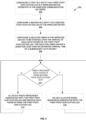
- Figure 2 depicts a state diagram of a network (e.g., the RAN) transitioning into and out of survival time mode, and the network actions taken in each state and at the transitions.
- a network e.g., the RAN
- the network configures and activates PDCP duplication.
- the network configures a discard timer for each duplication leg. For at least one duplication leg, the discard timer is at least equal to the PDB, and is less than the arrival time of a next packet (e.g., determined from the periodicity parameter in a TSCAI).
- the network configures an LCP restriction for a logical channel in at least one duplication leg, such that transmission is limited to radio resources that are currently intentionally unavailable - e.g., dependent on a configured but not activated CG.
- the UE receives and discards packets in the restricted PDCP duplication leg, such that no packets are transmitted from that duplication leg, and only a current packet is ready to transmit from that duplication leg at any time.
- the network Upon detecting a message not received within the PDB, the network enters survival time mode.
- survival time mode the network activates the radio resources for the restricted PDCP duplication leg - e.g., activating the configured but heretofore non-activated CG.
- the UE transmits packets on the restricted PDCP duplication leg. The packets are current because prior packets were discarded at or after the expiration of their PDB.
- the addition of radio resources (i.e., activation of the restricted PDCP duplication leg) to address the survival time situation is very fast - i.e., transmitting a CG in a DCI - particularly as compared to an RRC message or a MAC CE.
- the network When the network detects a message received within the PDB, it exits survival time mode.
- the network deactivates radio resources for the restricted PDCP duplication leg - e.g., de-activating the configured CG.
- the UE ceases transmitting packets in the restricted PDCP duplication leg, but continues transmitting packets in non-restricted PDCP duplication leg(s).
- the UE discards packets in the restricted PDCP duplication leg without transmitting them, so that only a current packet is ready to transmit at any time.
- FIG. 3 depicts a method 100 in accordance with particular aspects.
- the method 100 is performed by a wireless device operative in a wireless communication network.
- the method 100 is a method of transmitting uplink data packets in a data flow implementing Packet Data Convergence Protocol (PDCP) packet duplication.
- PDCP Packet Data Convergence Protocol
- a first Radio Link Control (RLC) entity is operated as a first PDCP duplication leg (block 102), and a second RLC entity is operated as a second PDCP duplication leg (block 116).
- a discard timer having a duration less than an estimated arrival time of a subsequent data packet, is started (block 106).
- each packet is discarded, without transmitting it (block 112).
- data packets are transmitted to the network utilizing the allocated radio resources (block 114).
- FIG. 4 depicts a method 200 in accordance with other particular aspects.
- the method 200 is performed by a base station operative in a wireless communication network.
- the method 200 is a method of controlling the transmission of uplink data packets in a data flow implementing Packet Data Convergence Protocol (PDCP) packet duplication.
- PDCP Packet Data Convergence Protocol
- a first Radio Link Control (RLC) entity is configured as a first PDCP duplication leg in a wireless device operative in the wireless communication network (block 202), and a second RLC entity is configured as a second PDCP duplication leg in the wireless device (block 204).
- a discard timer is configured in the wireless device to be started upon the actual or estimated arrival of each data packet in the first PDCP duplication leg (block 206).
- the discard timer has a duration less than an estimated arrival time of a subsequent data packet.
- radio resources associated with the first PDCP duplication leg are not allocated (block 210).
- radio resources associated with the first PDCP duplication leg are allocated, and data packets from the first PDCP duplication leg are received (block 212).
- apparatuses described herein may perform the methods 100, 200 herein and any other processing by implementing any functional means, modules, units, or circuitry.
- the apparatuses comprise respective circuits or circuitry configured to perform the steps shown in the method figures.
- the circuits or circuitry in this regard may comprise circuits dedicated to performing certain functional processing and/or one or more microprocessors in conjunction with memory.
- the circuitry may include one or more microprocessor or microcontrollers, as well as other digital hardware, which may include digital signal processors (DSPs), special-purpose digital logic, and the like.
- DSPs digital signal processors
- the processing circuitry may be configured to execute program code stored in memory, which may include one or several types of memory such as read-only memory (ROM), random-access memory, cache memory, flash memory devices, optical storage devices, etc.
- Program code stored in memory may include program instructions for executing one or more telecommunications and/or data communications protocols as well as instructions for carrying out one or more of the techniques described herein, in several aspects.
- the memory stores program code that, when executed by the one or more processors, carries out the techniques described herein.
- FIG. 5 for example illustrates a hardware block diagram of a wireless device 10 as implemented in accordance with one or more aspects.
- a wireless device 10 is any type of device capable of communicating with a network node and/or access point using radio signals.
- a wireless device 10 may therefore refer to a machine-to-machine (M2M) device, a machine-type communications (MTC) device, a Narrowband Internet of Things (NB loT) device, etc.
- M2M machine-to-machine
- MTC machine-type communications
- N loT Narrowband Internet of Things
- the wireless device 10 may also be referred to as a User Equipment (UE), such as a cellular telephone or "smartphone," however, the term UE should be understood to encompass any wireless device 10.
- UE User Equipment
- a wireless device 10 may also be referred to as a radio device, a radio communication device, a wireless device, a wireless terminal, or simply a terminal - unless the context indicates otherwise, the use of any of these terms is intended to include device-to-device UEs or devices, machine-type devices, or devices capable of machine-to-machine communication, sensors equipped with a wireless device, wireless-enabled table computers, mobile terminals, smart phones, laptop-embedded equipped (LEE), laptop-mounted equipment (LME), USB dongles, wireless customer-premises equipment (CPE), etc.
- M2M machine-to-machine
- MTC machine-type communication
- wireless sensor and sensor may also be used. It should be understood that these devices, although referred to as UEs, but may be configured to transmit and/or receive data without direct human interaction.
- the wireless device 10 includes a user interface 12 (display, touchscreen, keyboard or keypad, microphone, speaker, and the like); in other aspects, such as in many M2M, MTC, or NB loT scenarios, the wireless device 10 may include only a minimal, or no, user interface 12 (as indicated by the dashed lines of block 12 in Figure 4 ).
- the wireless device 10 also includes processing circuitry 14; memory 16; and communication circuitry 18 connected to one or more antennas 20, to effect wireless communication across an air interface to one or more radio network nodes, such as a base station, and/or access points.
- the antenna(s) 20 may protrude externally from the wireless device 10, or the antenna(s) 20 may be internal.
- a wireless device 10 may include a sophisticated user interface 12, and may additionally include features such as a camera, accelerometer, satellite navigation signal receiver circuitry, vibrating motor, and the like (not depicted in Fig. 5 ).
- the memory 16 is operative to store, and the processing circuitry 14 operative to execute, software which when executed is operative to cause the wireless device 10 to transmit packets for a TCS QoS flow from a first PDCP duplication leg using restricted radio resources when the network is in survival time mode.
- the software when executed on the processing circuitry 14, is operative to perform the method 100 described and claimed herein.
- the processing circuitry 14 in this regard may implement certain functional means, units, or modules.
- Figure 6 illustrates a functional block diagram of a wireless device 30 in a wireless network according to still other aspects.
- the wireless device 30 implements various functional means, units, or modules, e.g., via the processing circuitry 14 in Figure 5 and/or via software code.
- These functional means, units, or modules, e.g., for implementing the method(s) herein, include for instance: a PDCP duplication leg operating unit 32, a packet discarding unit 34, and a packet transmitting unit 36.
- the network PDCP duplication leg operating unit 32 is configured to operate a first Radio Link Control (RLC) entity as a first PDCP duplication leg, and a second RLP entity as a second PDCP duplication leg.
- the packet discarding unit 34 is configured to, upon the actual or estimated arrival of each data packet in the first PDCP duplication leg, start a discard timer having a duration less than an estimated arrival time of a subsequent data packet, and in response to the unavailability of radio resources associated with the first PDCP duplication leg, discard each packet, without transmitting it, at the expiration of the discard timer.
- the packet transmitting unit 36 is configured to, in response to the network allocating radio resources associated with the first PDCP duplication leg, transmit data packets to the network utilizing the allocated radio resources.
- FIG. 7 depicts a hardware block diagram of a base station 50 operative in a wireless communication network.
- the base station 50 includes processing circuitry 52; memory 54; and communication circuitry 56 connected to one or more antennas 60, to effect wireless communication across an air interface to one or more wireless devices 10.
- the antenna(s) 60 may be physically located separately from the base station 50, such as mounted on a tower, building, or the like.
- the memory 56 is depicted as being internal to the processing circuitry 54, those of skill in the art understand that the memory 56 may also be external.
- the base station 50 is known in LTE as an eNodeB or eNB, and in New Radio (NR) as gNB. In general, in other wireless communication networks, the base station 50 may be known as a Radio Base Station, Base Transceiver Station, Access Point, or the like.
- the processing circuitry 54 is operative to cause the base station 50 to enter survival time mode upon detecting a missed packet in a TCS QoS flow, and in response to allocate additional radio resources to the TCS QoS flow until a packet is received within a Packet Delay Budget (PDB).
- PDB Packet Delay Budget
- the processing circuitry 54 is operative to perform the method 200 described and claimed herein.
- the processing circuitry 54 in this regard may implement certain functional means, units, or modules.
- Figure 8 illustrates a functional block diagram of a base station 70 in a wireless network according to still other aspects.
- the base station 72 implements various functional means, units, or modules, e.g., via the processing circuitry 52 in Figure 6 and/or via software code.
- These functional means, units, or modules, e.g., for implementing the method 200 herein, include for instance: PDCP duplication leg configuring unit 72, discard timer configuring unit 74, packet arrival monitoring unit 76, and radio resource (de)allocating unit 78.
- the PDCP duplication leg configuring unit 72 is configured to configure a first Radio Link Control (RLC) entity as a first PDCP duplication leg in a wireless device operative in the wireless communication network, and to configure a second RLC entity as a second PDCP duplication leg in the wireless device.
- the discard timer configuring unit 74 is configured to configure a discard timer in the wireless device to be started upon the actual or estimated arrival of each data packet in the first PDCP duplication leg, the discard timer having a duration less than an estimated arrival time of a subsequent data packet.
- the packet arrival monitoring unit 76 is configured to monitor the arrival of packets from the first and second PDCP duplication legs.
- the radio resource (de)allocating unit 78 is configured to, in response to timely receiving data packets from the second PDCP duplication leg, not allocate radio resources associated with the first PDCP duplication leg; and in response to not timely receiving data packets from the second PDCP duplication leg, allocate radio resources associated with the first PDCP duplication leg and receive data packets from the first PDCP duplication leg.
- a computer program comprises instructions which, when executed on at least one processor of an apparatus, cause the apparatus to carry out any of the respective processing described above.
- a computer program in this regard may comprise one or more code modules corresponding to the means or units described above.
- aspects further include a carrier containing such a computer program.
- This carrier may comprise one of an electronic signal, optical signal, radio signal, or computer readable storage medium.
- aspects herein also include a computer program product stored on a non-transitory computer readable (storage or recording) medium and comprising instructions that, when executed by a processor of an apparatus, cause the apparatus to perform as described above.
- aspects further include a computer program product comprising program code portions for performing the steps of any of the aspects herein when the computer program product is executed by a computing device.
- This computer program product may be stored on a computer readable recording medium.
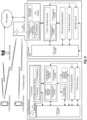
- a wireless network such as the example wireless network illustrated in Figure 9 .
- the wireless network of Figure 9 only depicts network 1106, network nodes 1160 and 1160b, and WDs 1110, 1110b, and 1110c.
- a wireless network may further include any additional elements suitable to support communication between wireless devices or between a wireless device and another communication device, such as a landline telephone, a service provider, or any other network node or end device.
- network node 1160 and wireless device (WD) 1110 are depicted with additional detail.
- the wireless network may provide communication and other types of services to one or more wireless devices to facilitate the wireless devices' access to and/or use of the services provided by, or via, the wireless network.
- the wireless network may comprise and/or interface with any type of communication, telecommunication, data, cellular, and/or radio network or other similar type of system.
- the wireless network may be configured to operate according to specific standards or other types of predefined rules or procedures.
- particular aspects of the wireless network may implement communication standards, such as Global System for Mobile Communications (GSM), Universal Mobile Telecommunications System (UMTS), Long Term Evolution (LTE), Narrowband Internet of Things (NB-IoT), and/or other suitable 2G, 3G, 4G, or 5G standards; wireless local area network (WLAN) standards, such as the IEEE 802.11 standards; and/or any other appropriate wireless communication standard, such as the Worldwide Interoperability for Microwave Access (WiMax), Bluetooth, Z-Wave and/or ZigBee standards.
- GSM Global System for Mobile Communications
- UMTS Universal Mobile Telecommunications System
- LTE Long Term Evolution
- NB-IoT Narrowband Internet of Things
- WLAN wireless local area network
- WiMax Worldwide Interoperability
- Network 1106 may comprise one or more backhaul networks, core networks, IP networks, public switched telephone networks (PSTNs), packet data networks, optical networks, wide-area networks (WANs), local area networks (LANs), wireless local area networks (WLANs), wired networks, wireless networks, metropolitan area networks, and other networks to enable communication between devices.
- PSTNs public switched telephone networks
- WANs wide-area networks
- LANs local area networks
- WLANs wireless local area networks
- wired networks wireless networks, metropolitan area networks, and other networks to enable communication between devices.
- Network node 1160 and WD 1110 comprise various components described in more detail below. These components work together in order to provide network node and/or wireless device functionality, such as providing wireless connections in a wireless network.
- the wireless network may comprise any number of wired or wireless networks, network nodes, base stations, controllers, wireless devices, relay stations, and/or any other components or systems that may facilitate or participate in the communication of data and/or signals whether via wired or wireless connections.
- network node refers to equipment capable, configured, arranged and/or operable to communicate directly or indirectly with a wireless device and/or with other network nodes or equipment in the wireless network to enable and/or provide wireless access to the wireless device and/or to perform other functions (e.g., administration) in the wireless network.
- network nodes include, but are not limited to, access points (APs) (e.g., radio access points), base stations (BSs) (e.g., radio base stations, Node Bs, evolved Node Bs (eNBs) and NR NodeBs (gNBs)).
- APs access points
- BSs base stations
- eNBs evolved Node Bs
- gNBs NR NodeBs
- Base stations may be categorized based on the amount of coverage they provide (or, stated differently, their transmit power level) and may then also be referred to as femto base stations, pico base stations, micro base stations, or macro base stations.
- a base station may be a relay node or a relay donor node controlling a relay.
- a network node may also include one or more (or all) parts of a distributed radio base station such as centralized digital units and/or remote radio units (RRUs), sometimes referred to as Remote Radio Heads (RRHs). Such remote radio units may or may not be integrated with an antenna as an antenna integrated radio.
- RRUs remote radio units
- RRHs Remote Radio Heads
- Such remote radio units may or may not be integrated with an antenna as an antenna integrated radio.
- Parts of a distributed radio base station may also be referred to as nodes in a distributed antenna system (DAS).
- DAS distributed antenna system
- network nodes include multi-standard radio (MSR) equipment such as MSR BSs, network controllers such as radio network controllers (RNCs) or base station controllers (BSCs), base transceiver stations (BTSs), transmission points, transmission nodes, multi-cell/multicast coordination entities (MCEs), core network nodes (e.g., MSCs, MMEs), O&M nodes, OSS nodes, SON nodes, positioning nodes (e.g., E-SMLCs), and/or MDTs.
- MSR multi-standard radio
- RNCs radio network controllers
- BSCs base station controllers
- BTSs base transceiver stations
- transmission points transmission nodes
- MCEs multi-cell/multicast coordination entities
- core network nodes e.g., MSCs, MMEs
- O&M nodes e.g., OSS nodes
- SON nodes e.g., SON nodes
- positioning nodes e.g., E-
- network nodes may represent any suitable device (or group of devices) capable, configured, arranged, and/or operable to enable and/or provide a wireless device with access to the wireless network or to provide some service to a wireless device that has accessed the wireless network.
- network node 1160 includes processing circuitry 1170, device readable medium 1180, interface 1190, auxiliary equipment 1184, power source 1186, power circuitry 1187, and antenna 1162.
- network node 1160 illustrated in the example wireless network of Figure 9 may represent a device that includes the illustrated combination of hardware components, other aspects may comprise network nodes with different combinations of components. It is to be understood that a network node comprises any suitable combination of hardware and/or software needed to perform the tasks, features, functions and methods disclosed herein.
- network node 1160 may comprise multiple different physical components that make up a single illustrated component (e.g., device readable medium 1180 may comprise multiple separate hard drives as well as multiple RAM modules).
- network node 1160 may be composed of multiple physically separate components (e.g., a NodeB component and a RNC component, or a BTS component and a BSC component, etc.), which may each have their own respective components.
- network node 1160 comprises multiple separate components (e.g., BTS and BSC components)
- one or more of the separate components may be shared among several network nodes.
- a single RNC may control multiple NodeB's.
- each unique NodeB and RNC pair may in some instances be considered a single separate network node.
- network node 1160 may be configured to support multiple radio access technologies (RATs).
- RATs radio access technologies
- Network node 1160 may also include multiple sets of the various illustrated components for different wireless technologies integrated into network node 1160, such as, for example, GSM, WCDMA, LTE, NR, WiFi, or Bluetooth wireless technologies. These wireless technologies may be integrated into the same or different chip or set of chips and other components within network node 1160.
- Processing circuitry 1170 is configured to perform any determining, calculating, or similar operations (e.g., certain obtaining operations) described herein as being provided by a network node. These operations performed by processing circuitry 1170 may include processing information obtained by processing circuitry 1170 by, for example, converting the obtained information into other information, comparing the obtained information or converted information to information stored in the network node, and/or performing one or more operations based on the obtained information or converted information, and as a result of said processing making a determination.
- processing information obtained by processing circuitry 1170 by, for example, converting the obtained information into other information, comparing the obtained information or converted information to information stored in the network node, and/or performing one or more operations based on the obtained information or converted information, and as a result of said processing making a determination.
- Processing circuitry 1170 may comprise a combination of one or more of a microprocessor, controller, microcontroller, central processing unit, digital signal processor, application-specific integrated circuit, field programmable gate array, or any other suitable computing device, resource, or combination of hardware, software and/or encoded logic operable to provide, either alone or in conjunction with other network node 1160 components, such as device readable medium 1180, network node 1160 functionality.
- processing circuitry 1170 may execute instructions stored in device readable medium 1180 or in memory within processing circuitry 1170. Such functionality may include providing any of the various wireless features, functions, or benefits discussed herein.
- processing circuitry 1170 may include a system on a chip (SOC).
- SOC system on a chip
- processing circuitry 1170 may include one or more of radio frequency (RF) transceiver circuitry 1172 and baseband processing circuitry 1174.
- radio frequency (RF) transceiver circuitry 1172 and baseband processing circuitry 1174 may be on separate chips (or sets of chips), boards, or units, such as radio units and digital units.
- part or all of RF transceiver circuitry 1172 and baseband processing circuitry 1174 may be on the same chip or set of chips, boards, or units
- processing circuitry 1170 executing instructions stored on device readable medium 1180 or memory within processing circuitry 1170.
- some or all of the functionality may be provided by processing circuitry 1170 without executing instructions stored on a separate or discrete device readable medium, such as in a hard-wired manner.
- processing circuitry 1170 can be configured to perform the described functionality. The benefits provided by such functionality are not limited to processing circuitry 1170 alone or to other components of network node 1160, but are enjoyed by network node 1160 as a whole, and/or by end users and the wireless network generally.
- Device readable medium 1180 may comprise any form of volatile or non-volatile computer readable memory including, without limitation, persistent storage, solid-state memory, remotely mounted memory, magnetic media, optical media, random access memory (RAM), read-only memory (ROM), mass storage media (for example, a hard disk), removable storage media (for example, a flash drive, a Compact Disk (CD) or a Digital Video Disk (DVD)), and/or any other volatile or non-volatile, non-transitory device readable and/or computer-executable memory devices that store information, data, and/or instructions that may be used by processing circuitry 1170.
- volatile or non-volatile computer readable memory including, without limitation, persistent storage, solid-state memory, remotely mounted memory, magnetic media, optical media, random access memory (RAM), read-only memory (ROM), mass storage media (for example, a hard disk), removable storage media (for example, a flash drive, a Compact Disk (CD) or a Digital Video Disk (DVD)), and/or any other volatile or
- Device readable medium 1180 may store any suitable instructions, data or information, including a computer program, software, an application including one or more of logic, rules, code, tables, etc. and/or other instructions capable of being executed by processing circuitry 1170 and, utilized by network node 1160.
- Device readable medium 1180 may be used to store any calculations made by processing circuitry 1170 and/or any data received via interface 1190.
- processing circuitry 1170 and device readable medium 1180 may be considered to be integrated.
- Interface 1190 is used in the wired or wireless communication of signalling and/or data between network node 1160, network 1106, and/or WDs 1110. As illustrated, interface 1190 comprises port(s)/terminal(s) 1194 to send and receive data, for example to and from network 1106 over a wired connection. Interface 1190 also includes radio front end circuitry 1192 that may be coupled to, or in certain aspects a part of, antenna 1162. Radio front end circuitry 1192 comprises filters 1198 and amplifiers 1196. Radio front end circuitry 1192 may be connected to antenna 1162 and processing circuitry 1170. Radio front end circuitry may be configured to condition signals communicated between antenna 1162 and processing circuitry 1170.
- Radio front end circuitry 1192 may receive digital data that is to be sent out to other network nodes or WDs via a wireless connection. Radio front end circuitry 1192 may convert the digital data into a radio signal having the appropriate channel and bandwidth parameters using a combination of filters 1198 and/or amplifiers 1196. The radio signal may then be transmitted via antenna 1162. Similarly, when receiving data, antenna 1162 may collect radio signals which are then converted into digital data by radio front end circuitry 1192. The digital data may be passed to processing circuitry 1170. In other aspects, the interface may comprise different components and/or different combinations of components.
- network node 1160 may not include separate radio front end circuitry 1192, instead, processing circuitry 1170 may comprise radio front end circuitry and may be connected to antenna 1162 without separate radio front end circuitry 1192.
- processing circuitry 1170 may comprise radio front end circuitry and may be connected to antenna 1162 without separate radio front end circuitry 1192.
- all or some of RF transceiver circuitry 1172 may be considered a part of interface 1190.
- interface 1190 may include one or more ports or terminals 1194, radio front end circuitry 1192, and RF transceiver circuitry 1172, as part of a radio unit (not shown), and interface 1190 may communicate with baseband processing circuitry 1174, which is part of a digital unit (not shown).
- Antenna 1162 may include one or more antennas, or antenna arrays, configured to send and/or receive wireless signals. Antenna 1162 may be coupled to radio front end circuitry 1190 and may be any type of antenna capable of transmitting and receiving data and/or signals wirelessly. In some aspects, antenna 1162 may comprise one or more omni-directional, sector or panel antennas operable to transmit/receive radio signals between, for example, 2 GHz and 66 GHz. An omni-directional antenna may be used to transmit/receive radio signals in any direction, a sector antenna may be used to transmit/receive radio signals from devices within a particular area, and a panel antenna may be a line of sight antenna used to transmit/receive radio signals in a relatively straight line. In some instances, the use of more than one antenna may be referred to as MIMO. In certain aspects, antenna 1162 may be separate from network node 1160 and may be connectable to network node 1160 through an interface or port.
- Antenna 1162, interface 1190, and/or processing circuitry 1170 may be configured to perform any receiving operations and/or certain obtaining operations described herein as being performed by a network node. Any information, data and/or signals may be received from a wireless device, another network node and/or any other network equipment. Similarly, antenna 1162, interface 1190, and/or processing circuitry 1170 may be configured to perform any transmitting operations described herein as being performed by a network node. Any information, data and/or signals may be transmitted to a wireless device, another network node and/or any other network equipment.
- Power circuitry 1187 may comprise, or be coupled to, power management circuitry and is configured to supply the components of network node 1160 with power for performing the functionality described herein. Power circuitry 1187 may receive power from power source 1186. Power source 1186 and/or power circuitry 1187 may be configured to provide power to the various components of network node 1160 in a form suitable for the respective components ( e.g., at a voltage and current level needed for each respective component). Power source 1186 may either be included in, or external to, power circuitry 1187 and/or network node 1160.
- network node 1160 may be connectable to an external power source (e.g., an electricity outlet) via an input circuitry or interface such as an electrical cable, whereby the external power source supplies power to power circuitry 1187.
- power source 1186 may comprise a source of power in the form of a battery or battery pack which is connected to, or integrated in, power circuitry 1187. The battery may provide backup power should the external power source fail.
- Other types of power sources such as photovoltaic devices, may also be used.
- network node 1160 may include additional components beyond those shown in Figure 9 that may be responsible for providing certain aspects of the network node's functionality, including any of the functionality described herein and/or any functionality necessary to support the subject matter described herein.
- network node 1160 may include user interface equipment to allow input of information into network node 1160 and to allow output of information from network node 1160. This may allow a user to perform diagnostic, maintenance, repair, and other administrative functions for network node 1160.
- wireless device refers to a device capable, configured, arranged and/or operable to communicate wirelessly with network nodes and/or other wireless devices.
- the term WD may be used interchangeably herein with user equipment (UE).
- Communicating wirelessly may involve transmitting and/or receiving wireless signals using electromagnetic waves, radio waves, infrared waves, and/or other types of signals suitable for conveying information through air.
- a WD may be configured to transmit and/or receive information without direct human interaction.
- a WD may be designed to transmit information to a network on a predetermined schedule, when triggered by an internal or external event, or in response to requests from the network.
- Examples of a WD include, but are not limited to, a smart phone, a mobile phone, a cell phone, a voice over IP (VoIP) phone, a wireless local loop phone, a desktop computer, a personal digital assistant (PDA), a wireless cameras, a gaming console or device, a music storage device, a playback appliance, a wearable terminal device, a wireless endpoint, a mobile station, a tablet, a laptop, a laptop-embedded equipment (LEE), a laptop-mounted equipment (LME), a smart device, a wireless customer-premise equipment (CPE). a vehicle-mounted wireless terminal device, etc.
- a WD may support device-to-device (D2D) communication, for example by implementing a 3GPP standard for sidelink communication, vehicle-to-vehicle (V2V), vehicle-to-infrastructure (V2I), vehicle-to-everything (V2X) and may in this case be referred to as a D2D communication device.
- D2D device-to-device
- V2V vehicle-to-vehicle
- V2I vehicle-to-infrastructure
- V2X vehicle-to-everything
- a WD may represent a machine or other device that performs monitoring and/or measurements, and transmits the results of such monitoring and/or measurements to another WD and/or a network node.
- the WD may in this case be a machine-to-machine (M2M) device, which may in a 3GPP context be referred to as an MTC device.
- M2M machine-to-machine
- the WD may be a UE implementing the 3GPP narrow band internet of things (NB-IoT) standard.
- NB-IoT narrow band internet of things
- machines or devices are sensors, metering devices such as power meters, industrial machinery, or home or personal appliances (e.g. refrigerators, televisions, etc.) personal wearables (e.g., watches, fitness trackers, etc.).
- a WD may represent a vehicle or other equipment that is capable of monitoring and/or reporting on its operational status or other functions associated with its operation.
- a WD as described above may represent the endpoint of a wireless connection, in which case the device may be referred to as a wireless terminal. Furthermore, a WD as described above may be mobile, in which case it may also be referred to as a mobile device or a mobile terminal.
- wireless device 1110 includes antenna 1111, interface 1114, processing circuitry 1120, device readable medium 1130, user interface equipment 1132, auxiliary equipment 1134, power source 1136 and power circuitry 1137.
- WD 1110 may include multiple sets of one or more of the illustrated components for different wireless technologies supported by WD 1110, such as, for example, GSM, WCDMA, LTE, NR, WiFi, WiMAX, NB-IoT, or Bluetooth wireless technologies, just to mention a few. These wireless technologies may be integrated into the same or different chips or set of chips as other components within WD 1110.
- Antenna 1111 may include one or more antennas or antenna arrays, configured to send and/or receive wireless signals, and is connected to interface 1114. In certain alternative aspects, antenna 1111 may be separate from WD 1110 and be connectable to WD 1110 through an interface or port. Antenna 1111, interface 1114, and/or processing circuitry 1120 may be configured to perform any receiving or transmitting operations described herein as being performed by a WD. Any information, data and/or signals may be received from a network node and/or another WD. In some aspects, radio front end circuitry and/or antenna 1111 may be considered an interface.
- interface 1114 comprises radio front end circuitry 1112 and antenna 1111.
- Radio front end circuitry 1112 comprise one or more filters 1118 and amplifiers 1116.
- Radio front end circuitry 1114 is connected to antenna 1111 and processing circuitry 1120, and is configured to condition signals communicated between antenna 1111 and processing circuitry 1120.
- Radio front end circuitry 1112 may be coupled to or a part of antenna 1111.
- WD 1110 may not include separate radio front end circuitry 1112; rather, processing circuitry 1120 may comprise radio front end circuitry and may be connected to antenna 1111.
- some or all of RF transceiver circuitry 1122 may be considered a part of interface 1114.
- Radio front end circuitry 1112 may receive digital data that is to be sent out to other network nodes or WDs via a wireless connection. Radio front end circuitry 1112 may convert the digital data into a radio signal having the appropriate channel and bandwidth parameters using a combination of filters 1118 and/or amplifiers 1116. The radio signal may then be transmitted via antenna 1111. Similarly, when receiving data, antenna 1111 may collect radio signals which are then converted into digital data by radio front end circuitry 1112. The digital data may be passed to processing circuitry 1120. In other aspects, the interface may comprise different components and/or different combinations of components.
- Processing circuitry 1120 may comprise a combination of one or more of a microprocessor, controller, microcontroller, central processing unit, digital signal processor, application-specific integrated circuit, field programmable gate array, or any other suitable computing device, resource, or combination of hardware, software, and/or encoded logic operable to provide, either alone or in conjunction with other WD 1110 components, such as device readable medium 1130, WD 1110 functionality. Such functionality may include providing any of the various wireless features or benefits discussed herein.
- processing circuitry 1120 may execute instructions stored in device readable medium 1130 or in memory within processing circuitry 1120 to provide the functionality disclosed herein.
- processing circuitry 1120 includes one or more of RF transceiver circuitry 1122, baseband processing circuitry 1124, and application processing circuitry 1126.
- the processing circuitry may comprise different components and/or different combinations of components.
- processing circuitry 1120 of WD 1110 may comprise a SOC.
- RF transceiver circuitry 1122, baseband processing circuitry 1124, and application processing circuitry 1126 may be on separate chips or sets of chips.
- part or all of baseband processing circuitry 1124 and application processing circuitry 1126 may be combined into one chip or set of chips, and RF transceiver circuitry 1122 may be on a separate chip or set of chips.
- part or all of RF transceiver circuitry 1122 and baseband processing circuitry 1124 may be on the same chip or set of chips, and application processing circuitry 1126 may be on a separate chip or set of chips.
- part or all of RF transceiver circuitry 1122, baseband processing circuitry 1124, and application processing circuitry 1126 may be combined in the same chip or set of chips.
- RF transceiver circuitry 1122 may be a part of interface 1114.
- RF transceiver circuitry 1122 may condition RF signals for processing circuitry 1120.
- processing circuitry 1120 executing instructions stored on device readable medium 1130, which in certain aspects may be a computer-readable storage medium.
- processing circuitry 1120 without executing instructions stored on a separate or discrete device readable storage medium, such as in a hard-wired manner.
- processing circuitry 1120 can be configured to perform the described functionality. The benefits provided by such functionality are not limited to processing circuitry 1120 alone or to other components of WD 1110, but are enjoyed by WD 1110 as a whole, and/or by end users and the wireless network generally.
- Processing circuitry 1120 may be configured to perform any determining, calculating, or similar operations (e.g., certain obtaining operations) described herein as being performed by a WD. These operations, as performed by processing circuitry 1120, may include processing information obtained by processing circuitry 1120 by, for example, converting the obtained information into other information, comparing the obtained information or converted information to information stored by WD 1110, and/or performing one or more operations based on the obtained information or converted information, and as a result of said processing making a determination.
- processing information obtained by processing circuitry 1120 by, for example, converting the obtained information into other information, comparing the obtained information or converted information to information stored by WD 1110, and/or performing one or more operations based on the obtained information or converted information, and as a result of said processing making a determination.
- Device readable medium 1130 may be operable to store a computer program, software, an application including one or more of logic, rules, code, tables, etc. and/or other instructions capable of being executed by processing circuitry 1120.
- Device readable medium 1130 may include computer memory (e.g., Random Access Memory (RAM) or Read Only Memory (ROM)), mass storage media (e.g., a hard disk), removable storage media (e.g., a Compact Disk (CD) or a Digital Video Disk (DVD)), and/or any other volatile or non-volatile, non-transitory device readable and/or computer executable memory devices that store information, data, and/or instructions that may be used by processing circuitry 1120.
- processing circuitry 1120 and device readable medium 1130 may be considered to be integrated.
- User interface equipment 1132 may provide components that allow for a human user to interact with WD 1110. Such interaction may be of many forms, such as visual, audial, tactile, etc. User interface equipment 1132 may be operable to produce output to the user and to allow the user to provide input to WD 1110. The type of interaction may vary depending on the type of user interface equipment 1132 installed in WD 1110. For example, if WD 1110 is a smart phone, the interaction may be via a touch screen; if WD 1110 is a smart meter, the interaction may be through a screen that provides usage ( e.g., the number of gallons used) or a speaker that provides an audible alert ( e.g., if smoke is detected).
- usage e.g., the number of gallons used
- a speaker that provides an audible alert
- User interface equipment 1132 may include input interfaces, devices and circuits, and output interfaces, devices and circuits. User interface equipment 1132 is configured to allow input of information into WD 1110, and is connected to processing circuitry 1120 to allow processing circuitry 1120 to process the input information. User interface equipment 1132 may include, for example, a microphone, a proximity or other sensor, keys/buttons, a touch display, one or more cameras, a USB port, or other input circuitry. User interface equipment 1132 is also configured to allow output of information from WD 1110, and to allow processing circuitry 1120 to output information from WD 1110. User interface equipment 1132 may include, for example, a speaker, a display, vibrating circuitry, a USB port, a headphone interface, or other output circuitry. Using one or more input and output interfaces, devices, and circuits, of user interface equipment 1132, WD 1110 may communicate with end users and/or the wireless network, and allow them to benefit from the functionality described herein.
- Auxiliary equipment 1134 is operable to provide more specific functionality which may not be generally performed by WDs. This may comprise specialized sensors for doing measurements for various purposes, interfaces for additional types of communication such as wired communications etc. The inclusion and type of components of auxiliary equipment 1134 may vary depending on the aspect and/or scenario.
- Power source 1136 may, in some aspects, be in the form of a battery or battery pack. Other types of power sources, such as an external power source (e.g., an electricity outlet), photovoltaic devices or power cells, may also be used.
- WD 1110 may further comprise power circuitry 1137 for delivering power from power source 1136 to the various parts of WD 1110 which need power from power source 1136 to carry out any functionality described or indicated herein.
- Power circuitry 1137 may in certain aspects comprise power management circuitry.
- Power circuitry 1137 may additionally or alternatively be operable to receive power from an external power source; in which case WD 1110 may be connectable to the external power source (such as an electricity outlet) via input circuitry or an interface such as an electrical power cable.
- Power circuitry 1137 may also in certain aspects be operable to deliver power from an external power source to power source 1136. This may be, for example, for the charging of power source 1136. Power circuitry 1137 may perform any formatting, converting, or other modification to the power from power source 1136 to make the power suitable for the respective components of WD 1110 to which power is supplied.
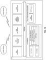
- Figure 10 illustrates one aspect of a UE in accordance with various aspects described herein.
- a user equipment or UE may not necessarily have a user in the sense of a human user who owns and/or operates the relevant device.
- a UE may represent a device that is intended for sale to, or operation by, a human user but which may not, or which may not initially, be associated with a specific human user (e.g., a smart sprinkler controller).
- a UE may represent a device that is not intended for sale to, or operation by, an end user but which may be associated with or operated for the benefit of a user (e.g., a smart power meter).
- UE 12200 may be any UE identified by the 3rd Generation Partnership Project (3GPP), including a NB-loT UE, a machine type communication (MTC) UE, and/or an enhanced MTC (eMTC) UE.
- UE 1200 is one example of a WD configured for communication in accordance with one or more communication standards promulgated by the 3rd Generation Partnership Project (3GPP), such as 3GPP's GSM, UMTS, LTE, and/or 5G standards.
- 3GPP 3rd Generation Partnership Project
- the term WD and UE may be used interchangeable. Accordingly, although Figure 10 is a UE, the components discussed herein are equally applicable to a WD, and vice-versa.
- UE 1200 includes processing circuitry 1201 that is operatively coupled to input/output interface 1205, radio frequency (RF) interface 1209, network connection interface 1211, memory 1215 including random access memory (RAM) 1217, read-only memory (ROM) 1219, and storage medium 1221 or the like, communication subsystem 1231, power source 1233, and/or any other component, or any combination thereof.
- Storage medium 1221 includes operating system 1223, application program 1225, and data 1227. In other aspects, storage medium 1221 may include other similar types of information.
- Certain UEs may utilize all of the components shown in Figure 10 , or only a subset of the components. The level of integration between the components may vary from one UE to another UE. Further, certain UEs may contain multiple instances of a component, such as multiple processors, memories, transceivers, transmitters, receivers, etc.
- processing circuitry 1201 may be configured to process computer instructions and data.
- Processing circuitry 1201 may be configured to implement any sequential state machine operative to execute machine instructions stored as machine-readable computer programs in the memory, such as one or more hardware-implemented state machines (e.g., in discrete logic, FPGA, ASIC, etc.); programmable logic together with appropriate firmware; one or more stored program, general-purpose processors, such as a microprocessor or Digital Signal Processor (DSP), together with appropriate software; or any combination of the above.
- the processing circuitry 1201 may include two central processing units (CPUs). Data may be information in a form suitable for use by a computer.
- input/output interface 1205 may be configured to provide a communication interface to an input device, output device, or input and output device.
- UE 1200 may be configured to use an output device via input/output interface 1205.
- An output device may use the same type of interface port as an input device.
- a USB port may be used to provide input to and output from UE 1200.
- the output device may be a speaker, a sound card, a video card, a display, a monitor, a printer, an actuator, an emitter, a smartcard, another output device, or any combination thereof.
- UE 1200 may be configured to use an input device via input/output interface 1205 to allow a user to capture information into UE 1200.
- the input device may include a touch-sensitive or presence-sensitive display, a camera (e.g., a digital camera, a digital video camera, a web camera, etc.), a microphone, a sensor, a mouse, a trackball, a directional pad, a trackpad, a scroll wheel, a smartcard, and the like.
- the presence-sensitive display may include a capacitive or resistive touch sensor to sense input from a user.
- a sensor may be, for instance, an accelerometer, a gyroscope, a tilt sensor, a force sensor, a magnetometer, an optical sensor, a proximity sensor, another like sensor, or any combination thereof.
- the input device may be an accelerometer, a magnetometer, a digital camera, a microphone, and an optical sensor.
- RF interface 1209 may be configured to provide a communication interface to RF components such as a transmitter, a receiver, and an antenna.
- Network connection interface 1211 may be configured to provide a communication interface to network 1243a.
- Network 1243a may encompass wired and/or wireless networks such as a local-area network (LAN), a wide-area network (WAN), a computer network, a wireless network, a telecommunications network, another like network or any combination thereof.
- network 1243a may comprise a Wi-Fi network.
- Network connection interface 1211 may be configured to include a receiver and a transmitter interface used to communicate with one or more other devices over a communication network according to one or more communication protocols, such as Ethernet, TCP/IP, SONET, ATM, or the like.
- Network connection interface 1211 may implement receiver and transmitter functionality appropriate to the communication network links ( e.g., optical, electrical, and the like). The transmitter and receiver functions may share circuit components, software or firmware, or alternatively may be implemented separately.
- RAM 1217 may be configured to interface via bus 1202 to processing circuitry 1201 to provide storage or caching of data or computer instructions during the execution of software programs such as the operating system, application programs, and device drivers.
- ROM 1219 may be configured to provide computer instructions or data to processing circuitry 1201.
- ROM 1219 may be configured to store invariant low-level system code or data for basic system functions such as basic input and output (I/O), startup, or reception of keystrokes from a keyboard that are stored in a non-volatile memory.
- Storage medium 1221 may be configured to include memory such as RAM, ROM, programmable read-only memory (PROM), erasable programmable read-only memory (EPROM), electrically erasable programmable read-only memory (EEPROM), magnetic disks, optical disks, floppy disks, hard disks, removable cartridges, or flash drives.
- storage medium 1221 may be configured to include operating system 1223, application program 1225 such as a web browser application, a widget or gadget engine or another application, and data file 1227.
- Storage medium 1221 may store, for use by UE 1200, any of a variety of various operating systems or combinations of operating systems.
- Storage medium 1221 may be configured to include a number of physical drive units, such as redundant array of independent disks (RAID), floppy disk drive, flash memory, USB flash drive, external hard disk drive, thumb drive, pen drive, key drive, high-density digital versatile disc (HD-DVD) optical disc drive, internal hard disk drive, Blu-Ray optical disc drive, holographic digital data storage (HDDS) optical disc drive, external mini-dual in-line memory module (DIMM), synchronous dynamic random access memory (SDRAM), external micro-DIMM SDRAM, smartcard memory such as a subscriber identity module or a removable user identity (SIM/RUIM) module, other memory, or any combination thereof.
- RAID redundant array of independent disks
- HD-DVD high-density digital versatile disc
- HDDS holographic digital data storage
- DIMM external mini-dual in-line memory module
- SDRAM synchronous dynamic random access memory
- SDRAM synchronous dynamic random access memory
- smartcard memory such as a subscriber identity module or a removable user
- Storage medium 1221 may allow UE 1200 to access computer-executable instructions, application programs or the like, stored on transitory or non-transitory memory media, to off-load data, or to upload data.
- An article of manufacture, such as one utilizing a communication system may be tangibly embodied in storage medium 1221, which may comprise a device readable medium.
- processing circuitry 1201 may be configured to communicate with network 1243b using communication subsystem 1231.
- Network 1243a and network 1243b may be the same network or networks or different network or networks.
- Communication subsystem 1231 may be configured to include one or more transceivers used to communicate with network 1243b.
- communication subsystem 1231 may be configured to include one or more transceivers used to communicate with one or more remote transceivers of another device capable of wireless communication such as another WD, UE, or base station of a radio access network (RAN) according to one or more communication protocols, such as IEEE 802.10, CDMA, WCDMA, GSM, LTE, UTRAN, WiMax, or the like.
- RAN radio access network
- Each transceiver may include transmitter 1233 and/or receiver 1235 to implement transmitter or receiver functionality, respectively, appropriate to the RAN links ( e.g., frequency allocations and the like). Further, transmitter 1233 and receiver 1235 of each transceiver may share circuit components, software or firmware, or alternatively may be implemented separately.
- the communication functions of communication subsystem 1231 may include data communication, voice communication, multimedia communication, short-range communications such as Bluetooth, near-field communication, location-based communication such as the use of the global positioning system (GPS) to determine a location, another like communication function, or any combination thereof.
- communication subsystem 1231 may include cellular communication, Wi-Fi communication, Bluetooth communication, and GPS communication.
- Network 1243b may encompass wired and/or wireless networks such as a local-area network (LAN), a wide-area network (WAN), a computer network, a wireless network, a telecommunications network, another like network or any combination thereof.
- network 1243b may be a cellular network, a Wi-Fi network, and/or a near-field network.
- Power source 1213 may be configured to provide alternating current (AC) or direct current (DC) power to components of UE 1200.
- communication subsystem 1231 may be configured to include any of the components described herein.
- processing circuitry 1201 may be configured to communicate with any of such components over bus 1202.
- any of such components may be represented by program instructions stored in memory that when executed by processing circuitry 1201 perform the corresponding functions described herein.
- the functionality of any of such components may be partitioned between processing circuitry 1201 and communication subsystem 1231.
- the non-computationally intensive functions of any of such components may be implemented in software or firmware and the computationally intensive functions may be implemented in hardware.
- FIG 11 is a schematic block diagram illustrating a virtualization environment 1300 in which functions implemented by some aspects may be virtualized.
- virtualizing means creating virtual versions of apparatuses or devices which may include virtualizing hardware platforms, storage devices and networking resources.
- virtualization can be applied to a node (e.g., a virtualized base station or a virtualized radio access node) or to a device ( e.g., a UE, a wireless device or any other type of communication device) or components thereof and relates to an implementation in which at least a portion of the functionality is implemented as one or more virtual components (e.g., via one or more applications, components, functions, virtual machines or containers executing on one or more physical processing nodes in one or more networks).
- some or all of the functions described herein may be implemented as virtual components executed by one or more virtual machines implemented in one or more virtual environments 1300 hosted by one or more of hardware nodes 1330. Further, in aspects in which the virtual node is not a radio access node or does not require radio connectivity (e.g., a core network node), then the network node may be entirely virtualized.
- the functions may be implemented by one or more applications 1320 (which may alternatively be called software instances, virtual appliances, network functions, virtual nodes, virtual network functions, etc.) operative to implement some of the features, functions, and/or benefits of some of the aspects disclosed herein.
- Applications 1320 are run in virtualization environment 1300 which provides hardware 1330 comprising processing circuitry 1360 and memory 1390.
- Memory 1390 contains instructions 1395 executable by processing circuitry 1360 whereby application 1320 is operative to provide one or more of the features, benefits, and/or functions disclosed herein.
- Virtualization environment 1300 comprises general-purpose or special-purpose network hardware devices 1330 comprising a set of one or more processors or processing circuitry 1360, which may be commercial off-the-shelf (COTS) processors, dedicated Application Specific Integrated Circuits (ASICs), or any other type of processing circuitry including digital or analog hardware components or special purpose processors.
- processors or processing circuitry 1360 which may be commercial off-the-shelf (COTS) processors, dedicated Application Specific Integrated Circuits (ASICs), or any other type of processing circuitry including digital or analog hardware components or special purpose processors.
- Each hardware device may comprise memory 1390-1 which may be non-persistent memory for temporarily storing instructions 1395 or software executed by processing circuitry 1360.
- Each hardware device may comprise one or more network interface controllers (NICs) 1370, also known as network interface cards, which include physical network interface 1380.
- NICs network interface controllers
- Each hardware device may also include non-transitory, persistent, machine-readable storage media 1390-2 having stored therein software 1395 and/or instructions executable by processing circuitry 1360.
- Software 1395 may include any type of software including software for instantiating one or more virtualization layers 1350 (also referred to as hypervisors), software to execute virtual machines 1340 as well as software allowing it to execute functions, features and/or benefits described in relation with some aspects described herein.
- Virtual machines 1340 comprise virtual processing, virtual memory, virtual networking or interface and virtual storage, and may be run by a corresponding virtualization layer 1350 or hypervisor. Different aspects of the instance of virtual appliance 1320 may be implemented on one or more of virtual machines 1340, and the implementations may be made in different ways.
- processing circuitry 1360 executes software 1395 to instantiate the hypervisor or virtualization layer 1350, which may sometimes be referred to as a virtual machine monitor (VMM).
- VMM virtual machine monitor
- Virtualization layer 1350 may present a virtual operating platform that appears like networking hardware to virtual machine 1340.
- hardware 1330 may be a standalone network node with generic or specific components. Hardware 1330 may comprise antenna 13225 and may implement some functions via virtualization. Alternatively, hardware 1330 may be part of a larger cluster of hardware (e.g. such as in a data center or customer premise equipment (CPE)) where many hardware nodes work together and are managed via management and orchestration (MANO) 13100, which, among others, oversees lifecycle management of applications 1320.
- CPE customer premise equipment
- NFV network function virtualization
- NFV may be used to consolidate many network equipment types onto industry standard high volume server hardware, physical switches, and physical storage, which can be located in data centers, and customer premise equipment.
- virtual machine 1340 may be a software implementation of a physical machine that runs programs as if they were executing on a physical, non-virtualized machine.
- Each of virtual machines 1340, and that part of hardware 1330 that executes that virtual machine be it hardware dedicated to that virtual machine and/or hardware shared by that virtual machine with others of the virtual machines 1340, forms a separate virtual network elements (VNE).
- VNE virtual network elements
- VNF Virtual Network Function
- one or more radio units 13200 that each include one or more transmitters 13220 and one or more receivers 13210 may be coupled to one or more antennas 13225.
- Radio units 13200 may communicate directly with hardware nodes 1330 via one or more appropriate network interfaces and may be used in combination with the virtual components to provide a virtual node with radio capabilities, such as a radio access node or a base station.
- control system 13230 which may alternatively be used for communication between the hardware nodes 1330 and radio units 13200.
- a communication system includes telecommunication network 1410, such as a 3GPP-type cellular network, which comprises access network 1411, such as a radio access network, and core network 1414.
- Access network 1411 comprises a plurality of base stations 1412a, 1412b, 1412c, such as NBs, eNBs, gNBs or other types of wireless access points, each defining a corresponding coverage area 1413a, 1413b, 1413c.
- Each base station 1412a, 1412b, 1412c is connectable to core network 1414 over a wired or wireless connection 1415.
- a first UE 1491 located in coverage area 1413c is configured to wirelessly connect to, or be paged by, the corresponding base station 1412c.
- a second UE 1492 in coverage area 1413a is wirelessly connectable to the corresponding base station 1412a. While a plurality of UEs 1491, 1492 are illustrated in this example, the disclosed aspects are equally applicable to a situation where a sole UE is in the coverage area or where a sole UE is connecting to the corresponding base station 1412.
- Telecommunication network 1410 is itself connected to host computer 1430, which may be embodied in the hardware and/or software of a standalone server, a cloud-implemented server, a distributed server or as processing resources in a server farm.
- Host computer 1430 may be under the ownership or control of a service provider, or may be operated by the service provider or on behalf of the service provider.
- Connections 1421 and 1422 between telecommunication network 1410 and host computer 1430 may extend directly from core network 1414 to host computer 1430 or may go via an optional intermediate network 1420.
- Intermediate network 1420 may be one of, or a combination of more than one of, a public, private or hosted network; intermediate network 1420, if any, may be a backbone network or the Internet; in particular, intermediate network 1420 may comprise two or more sub-networks (not shown).
- the communication system of Figure 12 as a whole enables connectivity between the connected UEs 1491, 1492 and host computer 1430.
- the connectivity may be described as an over-the-top (OTT) connection 1450.
- Host computer 1430 and the connected UEs 1491, 1492 are configured to communicate data and/or signaling via OTT connection 1450, using access network 1411, core network 1414, any intermediate network 1420 and possible further infrastructure (not shown) as intermediaries.
- OTT connection 1450 may be transparent in the sense that the participating communication devices through which OTT connection 1450 passes are unaware of routing of uplink and downlink communications.
- base station 1412 may not or need not be informed about the past routing of an incoming downlink communication with data originating from host computer 1430 to be forwarded ( e.g., handed over) to a connected UE 1491. Similarly, base station 1412 need not be aware of the future routing of an outgoing uplink communication originating from the UE 1491 towards the host computer 1430.
- FIG. 13 illustrates host computer communicating via a base station with a user equipment over a partially wireless connection in accordance with some aspects
- host computer 1510 comprises hardware 1515 including communication interface 1516 configured to set up and maintain a wired or wireless connection with an interface of a different communication device of communication system 1500.
- Host computer 1510 further comprises processing circuitry 1518, which may have storage and/or processing capabilities.
- processing circuitry 1518 may comprise one or more programmable processors, application-specific integrated circuits, field programmable gate arrays or combinations of these (not shown) adapted to execute instructions.
- Host computer 1510 further comprises software 1511, which is stored in or accessible by host computer 1510 and executable by processing circuitry 1518.
- Software 1511 includes host application 1512.
- Host application 1512 may be operable to provide a service to a remote user, such as UE 1530 connecting via OTT connection 1550 terminating at UE 1530 and host computer 1510. In providing the service to the remote user, host application 1512 may provide user data which is transmitted using OTT connection 1550.
- Communication system 1500 further includes base station 1520 provided in a telecommunication system and comprising hardware 1525 enabling it to communicate with host computer 1510 and with UE 1530.
- Hardware 1525 may include communication interface 1526 for setting up and maintaining a wired or wireless connection with an interface of a different communication device of communication system 1500, as well as radio interface 1527 for setting up and maintaining at least wireless connection 1570 with UE 1530 located in a coverage area (not shown in Figure 13 ) served by base station 1520.
- Communication interface 1526 may be configured to facilitate connection 1560 to host computer 1510. Connection 1560 may be direct or it may pass through a core network (not shown in Figure 13 ) of the telecommunication system and/or through one or more intermediate networks outside the telecommunication system.
- hardware 1525 of base station 1520 further includes processing circuitry 1528, which may comprise one or more programmable processors, application-specific integrated circuits, field programmable gate arrays or combinations of these (not shown) adapted to execute instructions.
- processing circuitry 1528 may comprise one or more programmable processors, application-specific integrated circuits, field programmable gate arrays or combinations of these (not shown) adapted to execute instructions.
- Base station 1520 further has software 1521 stored internally or accessible via an external connection.
- Communication system 1500 further includes UE 1530 already referred to. Its hardware 1535 may include radio interface 1537 configured to set up and maintain wireless connection 1570 with a base station serving a coverage area in which UE 1530 is currently located. Hardware 1535 of UE 1530 further includes processing circuitry 1538, which may comprise one or more programmable processors, application-specific integrated circuits, field programmable gate arrays or combinations of these (not shown) adapted to execute instructions.
- UE 1530 further comprises software 1531, which is stored in or accessible by UE 1530 and executable by processing circuitry 1538.
- Software 1531 includes client application 1532. Client application 1532 may be operable to provide a service to a human or non-human user via UE 1530, with the support of host computer 1510.
- an executing host application 1512 may communicate with the executing client application 1532 via OTT connection 1550 terminating at UE 1530 and host computer 1510.
- client application 1532 may receive request data from host application 1512 and provide user data in response to the request data.
- OTT connection 1550 may transfer both the request data and the user data.
- Client application 1532 may interact with the user to generate the user data that it provides.
- host computer 1510, base station 1520 and UE 1530 illustrated in Figure 13 may be similar or identical to host computer 1430, one of base stations 1412a, 1412b, 1412c and one of UEs 1491, 1492 of Figure 12 , respectively.
- the inner workings of these entities may be as shown in Figure 13 and independently, the surrounding network topology may be that of Figure 12 .
- OTT connection 1550 has been drawn abstractly to illustrate the communication between host computer 1510 and UE 1530 via base station 1520, without explicit reference to any intermediary devices and the precise routing of messages via these devices.
- Network infrastructure may determine the routing, which it may be configured to hide from UE 1530 or from the service provider operating host computer 1510, or both. While OTT connection 1550 is active, the network infrastructure may further take decisions by which it dynamically changes the routing (e.g., on the basis of load balancing consideration or reconfiguration of the network).
- Wireless connection 1570 between UE 1530 and base station 1520 is in accordance with the teachings of the aspects described throughout this disclosure.
- One or more of the various aspects improve the performance of OTT services provided to UE 1530 using OTT connection 1550, in which wireless connection 1570 forms the last segment. More precisely, the teachings of these aspects may improve packet delivery, and hence meet service level requirements in a TSC QoS flow, and thereby provide benefits such as reducing latency, meeting critical timing requirements, and improving UE battery savings.
- a measurement procedure may be provided for the purpose of monitoring data rate, latency and other factors on which the one or more aspects improve.
- the measurement procedure and/or the network functionality for reconfiguring OTT connection 1550 may be implemented in software 1511 and hardware 1515 of host computer 1510 or in software 1531 and hardware 1535 of UE 1530, or both.
- sensors (not shown) may be deployed in or in association with communication devices through which OTT connection 1550 passes; the sensors may participate in the measurement procedure by supplying values of the monitored quantities exemplified above, or supplying values of other physical quantities from which software 1511, 1531 may compute or estimate the monitored quantities.
- the reconfiguring of OTT connection 1550 may include message format, retransmission settings, preferred routing etc.; the reconfiguring need not affect base station 1520, and it may be unknown or imperceptible to base station 1520. Such procedures and functionalities may be known and practiced in the art.
- measurements may involve proprietary UE signaling facilitating host computer 1510's measurements of throughput, propagation times, latency and the like.
- the measurements may be implemented in that software 1511 and 1531 causes messages to be transmitted, in particular empty or 'dummy' messages, using OTT connection 1550 while it monitors propagation times, errors etc.
- FIG 14 is a flowchart illustrating a method implemented in a communication system, in accordance with one aspect.
- the communication system includes a host computer, a base station and a UE which may be those described with reference to Figures 12 and 13 .
- the host computer provides user data.
- substep 1611 (which may be optional) of step 1610, the host computer provides the user data by executing a host application.
- the host computer initiates a transmission carrying the user data to the UE.
- step 1630 the base station transmits to the UE the user data which was carried in the transmission that the host computer initiated, in accordance with the teachings of the aspects described throughout this disclosure.
- step 1640 the UE executes a client application associated with the host application executed by the host computer.
- FIG 15 is a flowchart illustrating a method implemented in a communication system, in accordance with one aspect.
- the communication system includes a host computer, a base station and a UE which may be those described with reference to Figures 12 and 13 .
- the host computer provides user data.
- the host computer provides the user data by executing a host application.
- the host computer initiates a transmission carrying the user data to the UE.
- the transmission may pass via the base station, in accordance with the teachings of the aspects described throughout this disclosure.
- step 1730 (which may be optional), the UE receives the user data carried in the transmission.
- FIG 16 is a flowchart illustrating a method implemented in a communication system, in accordance with one aspect.
- the communication system includes a host computer, a base station and a UE which may be those described with reference to Figures 12 and 13 .
- the UE receives input data provided by the host computer.
- the UE provides user data.
- substep 1821 (which may be optional) of step 1820, the UE provides the user data by executing a client application.
- substep 1811 (which may be optional) of step 1810, the UE executes a client application which provides the user data in reaction to the received input data provided by the host computer.
- the executed client application may further consider user input received from the user.
- the UE initiates, in substep 1830 (which may be optional), transmission of the user data to the host computer.
- step 1840 of the method the host computer receives the user data transmitted from the UE, in accordance with the teachings of the aspects described throughout this disclosure.
- FIG 17 is a flowchart illustrating a method implemented in a communication system, in accordance with one aspect.
- the communication system includes a host computer, a base station and a UE which may be those described with reference to Figures 12 and 13 .
- the base station receives user data from the UE.
- the base station initiates transmission of the received user data to the host computer.
- the host computer receives the user data carried in the transmission initiated by the base station.
- any appropriate steps, methods, features, functions, or benefits disclosed herein may be performed through one or more functional units or modules of one or more virtual apparatuses.
- Each virtual apparatus may comprise a number of these functional units.
- These functional units may be implemented via processing circuitry, which may include one or more microprocessor or microcontrollers, as well as other digital hardware, which may include digital signal processors (DSPs), special-purpose digital logic, and the like.
- the processing circuitry may be configured to execute program code stored in memory, which may include one or several types of memory such as read-only memory (ROM), random-access memory (RAM), cache memory, flash memory devices, optical storage devices, etc.
- Program code stored in memory includes program instructions for executing one or more telecommunications and/or data communications protocols as well as instructions for carrying out one or more of the techniques described herein.
- the processing circuitry may be used to cause the respective functional unit to perform corresponding functions according one or more aspects of the present disclosure.
- the network can utilize survival time to increase the spectral efficiency, while ensuring it meets the service level requirement, in particular for the case where the survival time is very short, e.g., 0.5 millisecond.
- the network can effectively activate the actual utilization of a PDCP duplication by a DCI command, which is faster and more reliable than the traditional MAC CE activation command.
- the network can pre-allocate a smaller set of resources needed for PDCP duplication.
- unit may have conventional meaning in the field of electronics, electrical devices and/or electronic devices and may include, for example, electrical and/or electronic circuitry, devices, modules, processors, memories, logic solid state and/or discrete devices, computer programs or instructions for carrying out respective tasks, procedures, computations, outputs, and/or displaying functions, and so on, such as those that are described herein.
- the term “configured to” means set up, organized, adapted, or arranged to operate in a particular way; the term is synonymous with "designed to.”
- substantially means nearly or essentially, but not necessarily completely; the term encompasses and accounts for mechanical or component value tolerances, measurement error, random variation, and similar sources of imprecision.
Landscapes
- Engineering & Computer Science (AREA)
- Signal Processing (AREA)
- Computer Networks & Wireless Communication (AREA)
- Computer Security & Cryptography (AREA)
- Quality & Reliability (AREA)
- Mobile Radio Communication Systems (AREA)
Claims (15)
- Verfahren (100), das von einer drahtlosen Vorrichtung (10, 30) durchgeführt wird, die in einem drahtlosen Kommunikationsnetzwerk operiert, zum Senden von Uplink-Datenpaketen in einem Datenfluss unter Implementierung von Paketdatenkonvergenzprotokoll-Paketduplizierung, PDCP-Paketduplizierung, wobei das Verfahren (100) Folgendes umfasst:Betreiben (102) einer ersten Funkverbindungssteuerungsentität, RLC-Entität, als einen ersten PDCP-Duplizierungsabschnitt;Betreiben (104) einer zweiten RLC-Entität als einen zweiten PDCP-Duplizierungsabschnitt;bei der tatsächlichen oder geschätzten Ankunft (104) jedes Datenpakets in dem ersten PDCP-Duplizierungsabschnitt Starten (106) eines Verwerfungszeitgebers mit einer Dauer, die kürzer als eine geschätzte Ankunftszeit eines nachfolgenden Datenpakets ist;in Reaktion auf die Nichtverfügbarkeit von Funkressourcen (108), die mit dem ersten PDCP-Duplizierungsabschnitt assoziiert sind, Verwerfen (112) jedes Datenpakets, ohne es zu senden, bei Ablauf des Verwerfungszeitgebers (110); undin Reaktion darauf, dass das Netzwerk Funkressourcen (108) zuweist, die mit dem ersten PDCP-Duplizierungsabschnitt assoziiert sind, Senden (114) von Datenpaketen an das Netzwerk unter Verwendung der zugewiesenen Funkressourcen.
- Verfahren (100) nach Anspruch 1, wobei der Datenfluss eine damit assoziierte Dienstqualitätsbeschränkung, QoS-Beschränkung, aufweist, wobei ferner der QoS-Datenfluss ein zeitempfindlicher Kommunikationsdatenfluss, TSC-Datenfluss, ist.
- Verfahren (100) nach Anspruch 1, wobei der Verwerfungszeitgeber für mindestens eines von Folgendem gestartet wird (106):bei der tatsächlichen Ankunft jedes Datenpakets an der PDCP- oder RLC-Schicht; odergemäß dem Burst-Ankunftszeitparameter, BAT-Parameter, in einer TSC-Unterstützungsinformation, TSCAI; oderwenn das PDCP- oder RLC-Paket an eine untere Schicht zur Übertragung übermittelt wird.
- Verfahren (100) nach Anspruch 1, wobei die Ankunftszeit eines nachfolgenden Datenpakets aus einer Paketperiodizität in einer TSC-Unterstützungsinformation, TSCAI, geschätzt wird.
- Verfahren (100) nach einem der vorhergehenden Ansprüche, wobei ein Logikkanal des ersten PDCP-Duplizierungsabschnitts mit einer Logikkanalprioritätsbeschränkung konfiguriert ist, sodass die mit dem ersten PDCP-Duplizierungsabschnitt assoziierten Funkressourcen nicht verfügbar sind, sofern sie nicht explizit durch das Netzwerk aktiviert werden, wobei optional die Funkressourcen, die nicht verfügbar sind, sofern sie nicht explizit durch das Netzwerk aktiviert werden, Folgendes umfassen: konfigurierte, aber nicht aktivierte Configured Grants, CG, oder dynamische Freigaben mit einem spezifischen PHY-Schicht-Index.
- Verfahren (100) nach einem der Ansprüche 1 bis 4, wobei ein Logikkanal des ersten PDCP-Duplizierungsabschnitts mit einer Logikkanalprioritätsbeschränkung konfiguriert ist, sodass die mit dem ersten PDCP-Duplizierungsabschnitt assoziierten Funkressourcen nur jede N-te Instanz des periodischen Verkehrs verfügbar sind, wobei die Funkressourcen, die nur jede N-te Instanz verfügbar sind, Folgendes umfassen: Configured Grants, CG, die konfiguriert sind, aber nur jede N-te Instanz aktiviert werden; oder dynamische Freigaben mit einem spezifischen PHY-Schicht-Index, die nur jede N-te Instanz erteilt werden.
- Verfahren (100) nach einem der vorhergehenden Ansprüche, wobei das Netzwerk bei Ersterkennung, dass ein Paket auf einer konfigurierten und aktivierten Funkressource nicht empfangen wurde, in eine Überlebenszeit eintritt, wobei optional das Netzwerk eine Überlebenszeit bei Empfang eines Pakets vor Ablauf der Überlebenszeit verlässt.
- Verfahren (200), das von einer Basisstation (50, 70) durchgeführt wird, die in einem drahtlosen Kommunikationsnetzwerk operiert, zum Steuern der Übertragung von Uplink-Datenpaketen in einem Datenfluss unter Implementierung von Paketdatenkonvergenzprotokoll-Paketduplizierung, PDCP-Paketduplizierung, wobei das Verfahren (200) Folgendes umfasst:Konfigurieren (202) einer ersten Funkverbindungssteuerungsentität, RLC-Entität, als einen ersten PDCP-Duplizierungsabschnitt in einer drahtlosen Vorrichtung (10, 30), die in dem drahtlosen Kommunikationsnetzwerk operiert;Konfigurieren (204) einer zweiten RLC-Entität als einen zweiten PDCP-Duplizierungsabschnitt in der drahtlosen Vorrichtung;Konfigurieren (204) eines Verwerfungszeitgebers in der drahtlosen Vorrichtung (10, 30), der bei der tatsächlichen oder geschätzten Ankunft jedes Datenpakets im ersten PDCP-Duplizierungsabschnitt gestartet werden soll, wobei der Verwerfungszeitgeber eine Dauer aufweist, die kürzer als eine geschätzte Ankunftszeit eines nachfolgenden Datenpakets ist, zum Verwerfen jedes Datenpakets, ohne es zu senden, bei Ablauf des Verwerfungszeitgebers in Reaktion auf die Nichtverfügbarkeit von Funkressourcen, die mit dem ersten PDCP-Abschnitt assoziiert sind;in Reaktion auf ein rechtzeitiges Empfangen von Datenpaketen (206) von dem zweiten PDCP-Duplizierungsabschnitt Nichtzuweisen von Funkressourcen (210), die mit dem ersten PDCP-Duplizierungsabschnitt assoziiert sind; undin Reaktion darauf, dass ein Datenpaket von dem zweiten PDCP-Duplizierungsabschnitt nicht rechtzeitig empfangen wird (206), Zuweisen (208) von Funkressourcen, die mit dem ersten PDCP-Duplizierungsabschnitt assoziiert sind, und Empfangen von Datenpaketen von dem ersten PDCP-Duplizierungsabschnitt.
- Verfahren (200) nach Anspruch 8, wobei der Datenfluss eine damit assoziierte Dienstqualitätsbeschränkung, QoS-Beschränkung, aufweist, wobei ferner der QoS-Datenfluss ein zeitempfindlicher Kommunikationsdatenfluss, TSC-Datenfluss, ist.
- Verfahren (200) nach Anspruch 8, wobei die drahtlose Vorrichtung (10, 30) so konfiguriert ist, dass sie den Verwerfungszeitgeber für mindestens eines von Folgendem startet:bei der tatsächlichen Ankunft jedes Datenpakets an der PDCP- oder RLC-Schicht; oderin Abstimmung mit einem Burst-Ankunftszeitparameter, BAT-Parameter, in einer TSC-Unterstützungsinformation, TSCAI; oderwenn das PDCP- oder RLC-Paket an eine untere Schicht zur Übertragung übermittelt wird.
- Verfahren (200) nach Anspruch 8, wobei die Ankunftszeit eines nachfolgenden Datenpakets aus einer Paketperiodizität in einer TSC-Unterstützungsinformation, TSCAI, geschätzt wird.
- Verfahren (200) nach einem der Ansprüche 8 bis 11, wobei das Zuweisen oder Nichtzuweisen von Funkressourcen, die mit dem ersten PDCP-Duplizierungsabschnitt assoziiert sind, ein Konfigurieren eines Logikkanals des PDCP-Duplizierungsabschnitts mit einer Logikkanalprioritätsbeschränkung, LCP-Beschränkung, umfasst, sodass die mit dem ersten PDCP-Duplizierungsabschnitt assoziierten Funkressourcen nicht verfügbar sind, sofern sie nicht explizit aktiviert werden, wobei optional die Funkressourcen, die nicht verfügbar sind, sofern sie nicht explizit aktiviert werden, Folgendes umfassen: konfigurierte, aber nicht aktivierte Configured Grants, CG, oder dynamische Freigaben mit einem spezifischen PHY-Schicht-Index.
- Verfahren (200) nach einem der Ansprüche 8 bis 12, wobei die Basisstation (50, 70) bei Ersterkennung, dass ein Paket auf einer konfigurierten und aktivierten Funkressource nicht empfangen wurde, in eine Überlebenszeit eintritt, wobei optional die Basisstation (50, 70) eine Überlebenszeit bei Empfang eines Pakets vor Ablauf der Überlebenszeit verlässt.
- Benutzereinrichtung, UE (10, 30), die in einem drahtlosen Kommunikationsnetzwerk operiert, um Uplink-Datenpakete in einem Datenfluss unter Implementierung von Paketdatenkonvergenzprotokoll-Paketduplizierung, PDCP-Paketduplizierung, zu senden, wobei die UE (10, 30) zum Durchführen eines oder einer Kombination der Ansprüche 1 bis 7 ausgelegt ist.
- Basisstation (50, 70), die in einem drahtlosen Kommunikationsnetzwerk operiert, um die Übertragung von Uplink-Datenpaketen in einem Datenfluss unter Implementierung von Paketdatenkonvergenzprotokoll-Paketduplizierung, PDCP-Paketduplizierung, zu steuern, wobei die Basisstation (50, 70) zum Durchführen eines oder einer Kombination der Ansprüche 8 bis 13 ausgelegt ist.
Applications Claiming Priority (2)
| Application Number | Priority Date | Filing Date | Title |
|---|---|---|---|
| US202163180821P | 2021-04-28 | 2021-04-28 | |
| PCT/EP2022/061278 WO2022229294A1 (en) | 2021-04-28 | 2022-04-27 | Selectively enabling pdcp duplication for survival time |
Publications (2)
| Publication Number | Publication Date |
|---|---|
| EP4331322A1 EP4331322A1 (de) | 2024-03-06 |
| EP4331322B1 true EP4331322B1 (de) | 2025-03-19 |
Family
ID=81850625
Family Applications (1)
| Application Number | Title | Priority Date | Filing Date |
|---|---|---|---|
| EP22726072.6A Active EP4331322B1 (de) | 2021-04-28 | 2022-04-27 | Selektive aktivierung von pdcp-duplizierung für überlebenszeit |
Country Status (3)
| Country | Link |
|---|---|
| US (1) | US20240373283A1 (de) |
| EP (1) | EP4331322B1 (de) |
| WO (1) | WO2022229294A1 (de) |
Families Citing this family (4)
| Publication number | Priority date | Publication date | Assignee | Title |
|---|---|---|---|---|
| US12382468B2 (en) * | 2021-07-21 | 2025-08-05 | Sharp Kabushiki Kaisha | Method and user equipment for handling a survival time state |
| WO2024205644A1 (en) * | 2023-03-31 | 2024-10-03 | Google Llc | Use of pdcp duplication as basis to control initiation of uplink data split |
| WO2025200026A1 (en) * | 2024-03-29 | 2025-10-02 | Nokia Shanghai Bell Co., Ltd. | Pdcp duplication |
| WO2025235133A1 (en) * | 2024-05-08 | 2025-11-13 | Apple Inc. | Jitter-aware user equipment operations |
Family Cites Families (8)
| Publication number | Priority date | Publication date | Assignee | Title |
|---|---|---|---|---|
| CN108419275B (zh) * | 2017-02-10 | 2022-01-14 | 华为技术有限公司 | 一种数据传输方法、通信设备、终端和基站 |
| US10716094B2 (en) * | 2017-03-23 | 2020-07-14 | Ofinno, Llc | Packet duplication in a wireless device and wireless network |
| CN108811175B (zh) * | 2017-05-05 | 2020-07-28 | 华硕电脑股份有限公司 | 无线通信系统中传送数据复制的方法和设备 |
| CN109729583B (zh) * | 2017-10-27 | 2021-06-25 | 维沃移动通信有限公司 | 一种无线资源配置方法、基站和用户终端 |
| US11129234B2 (en) * | 2018-02-13 | 2021-09-21 | FG Innovation Company Limited | Methods for packet data convergence protocol (PDCP) duplication operations and devices using the same |
| WO2020170043A2 (en) * | 2019-02-22 | 2020-08-27 | Lenovo (Singapore) Pte Ltd | Autonomously triggering retransmission of data |
| US11272397B2 (en) * | 2019-07-12 | 2022-03-08 | Nokia Technologies Oy | Flexible network control of uplink data duplication |
| CN113271551B (zh) * | 2020-02-17 | 2022-07-05 | 大唐移动通信设备有限公司 | 一种数据流传输方法、终端和网络侧设备 |
-
2022
- 2022-04-27 EP EP22726072.6A patent/EP4331322B1/de active Active
- 2022-04-27 WO PCT/EP2022/061278 patent/WO2022229294A1/en not_active Ceased
- 2022-04-27 US US18/288,716 patent/US20240373283A1/en active Pending
Also Published As
| Publication number | Publication date |
|---|---|
| US20240373283A1 (en) | 2024-11-07 |
| EP4331322A1 (de) | 2024-03-06 |
| WO2022229294A1 (en) | 2022-11-03 |
Similar Documents
| Publication | Publication Date | Title |
|---|---|---|
| US11196516B2 (en) | Methods for autonomous uplink transmissions and retransmissions | |
| EP3858053B1 (de) | Verbesserte uplink-planung in netzwerken mit integriertem zugangs-backhaul (iab) | |
| EP4331322B1 (de) | Selektive aktivierung von pdcp-duplizierung für überlebenszeit | |
| US12356413B2 (en) | Multiple grant handling in mixed services scenarios | |
| EP3707945B1 (de) | Verfahren und vorrichtung zur synchronisierung der übertragung kritischer daten | |
| EP3711185A1 (de) | Verfahren zur durchführung von funkverbindungsüberwachung | |
| US20220174683A1 (en) | Logical Channel Prioritization for Pre-Emption | |
| US12342347B2 (en) | Configured grant timer in intra-user equipment multiplexing | |
| US20220338211A1 (en) | Medium Access Control-Control Element Handling in Multi-Priority Traffic Environments | |
| EP4104616A1 (de) | Ressourcenkonfiguration mit direktzugriff in verschiedenen bandbreitenteilen für 2-schritt-direktzugriff | |
| CN114026948A (zh) | 两步无争用随机接入 | |
| US20200314658A1 (en) | Methods and apparatus for scheduling in laa | |
| US20230269646A1 (en) | Dual Active Protocol Stack (DAPS) Handover During URLLC Packet Duplication | |
| US20240298346A1 (en) | L1 Signal to Activate PDCP Duplication | |
| WO2022031197A1 (en) | Additional thresholds for dual connectivity data path switching | |
| EP4278508B1 (de) | Logische kanal-priorisierung im unlizenzierten spektrum | |
| US20230292306A1 (en) | Methods of autonomous transmission after cancellation | |
| US20230403614A1 (en) | Inter Base Station Handover with Dual Active Protocol Stack |
Legal Events
| Date | Code | Title | Description |
|---|---|---|---|
| STAA | Information on the status of an ep patent application or granted ep patent |
Free format text: STATUS: UNKNOWN |
|
| STAA | Information on the status of an ep patent application or granted ep patent |
Free format text: STATUS: THE INTERNATIONAL PUBLICATION HAS BEEN MADE |
|
| PUAI | Public reference made under article 153(3) epc to a published international application that has entered the european phase |
Free format text: ORIGINAL CODE: 0009012 |
|
| STAA | Information on the status of an ep patent application or granted ep patent |
Free format text: STATUS: REQUEST FOR EXAMINATION WAS MADE |
|
| 17P | Request for examination filed |
Effective date: 20231102 |
|
| AK | Designated contracting states |
Kind code of ref document: A1 Designated state(s): AL AT BE BG CH CY CZ DE DK EE ES FI FR GB GR HR HU IE IS IT LI LT LU LV MC MK MT NL NO PL PT RO RS SE SI SK SM TR |
|
| DAV | Request for validation of the european patent (deleted) | ||
| DAX | Request for extension of the european patent (deleted) | ||
| GRAP | Despatch of communication of intention to grant a patent |
Free format text: ORIGINAL CODE: EPIDOSNIGR1 |
|
| STAA | Information on the status of an ep patent application or granted ep patent |
Free format text: STATUS: GRANT OF PATENT IS INTENDED |
|
| RIC1 | Information provided on ipc code assigned before grant |
Ipc: H04L 69/22 20220101ALI20240913BHEP Ipc: H04W 28/02 20090101ALI20240913BHEP Ipc: H04L 5/00 20060101ALI20240913BHEP Ipc: H04L 1/08 20060101ALI20240913BHEP Ipc: H04W 72/04 20230101ALI20240913BHEP Ipc: H04L 69/28 20220101ALI20240913BHEP Ipc: H04L 69/14 20220101ALI20240913BHEP Ipc: H04W 80/02 20090101AFI20240913BHEP |
|
| INTG | Intention to grant announced |
Effective date: 20241018 |
|
| GRAS | Grant fee paid |
Free format text: ORIGINAL CODE: EPIDOSNIGR3 |
|
| GRAA | (expected) grant |
Free format text: ORIGINAL CODE: 0009210 |
|
| STAA | Information on the status of an ep patent application or granted ep patent |
Free format text: STATUS: THE PATENT HAS BEEN GRANTED |
|
| AK | Designated contracting states |
Kind code of ref document: B1 Designated state(s): AL AT BE BG CH CY CZ DE DK EE ES FI FR GB GR HR HU IE IS IT LI LT LU LV MC MK MT NL NO PL PT RO RS SE SI SK SM TR |
|
| REG | Reference to a national code |
Ref country code: GB Ref legal event code: FG4D |
|
| REG | Reference to a national code |
Ref country code: CH Ref legal event code: EP |
|
| REG | Reference to a national code |
Ref country code: DE Ref legal event code: R096 Ref document number: 602022012012 Country of ref document: DE |
|
| REG | Reference to a national code |
Ref country code: IE Ref legal event code: FG4D |
|
| REG | Reference to a national code |
Ref country code: NL Ref legal event code: FP |
|
| PGFP | Annual fee paid to national office [announced via postgrant information from national office to epo] |
Ref country code: NL Payment date: 20250427 Year of fee payment: 4 |
|
| PG25 | Lapsed in a contracting state [announced via postgrant information from national office to epo] |
Ref country code: RS Free format text: LAPSE BECAUSE OF FAILURE TO SUBMIT A TRANSLATION OF THE DESCRIPTION OR TO PAY THE FEE WITHIN THE PRESCRIBED TIME-LIMIT Effective date: 20250619 |
|
| PG25 | Lapsed in a contracting state [announced via postgrant information from national office to epo] |
Ref country code: FI Free format text: LAPSE BECAUSE OF FAILURE TO SUBMIT A TRANSLATION OF THE DESCRIPTION OR TO PAY THE FEE WITHIN THE PRESCRIBED TIME-LIMIT Effective date: 20250319 |
|
| PGFP | Annual fee paid to national office [announced via postgrant information from national office to epo] |
Ref country code: DE Payment date: 20250429 Year of fee payment: 4 |
|
| REG | Reference to a national code |
Ref country code: LT Ref legal event code: MG9D |
|
| PG25 | Lapsed in a contracting state [announced via postgrant information from national office to epo] |
Ref country code: NO Free format text: LAPSE BECAUSE OF FAILURE TO SUBMIT A TRANSLATION OF THE DESCRIPTION OR TO PAY THE FEE WITHIN THE PRESCRIBED TIME-LIMIT Effective date: 20250619 |
|
| PG25 | Lapsed in a contracting state [announced via postgrant information from national office to epo] |
Ref country code: HR Free format text: LAPSE BECAUSE OF FAILURE TO SUBMIT A TRANSLATION OF THE DESCRIPTION OR TO PAY THE FEE WITHIN THE PRESCRIBED TIME-LIMIT Effective date: 20250319 |
|
| PG25 | Lapsed in a contracting state [announced via postgrant information from national office to epo] |
Ref country code: LV Free format text: LAPSE BECAUSE OF FAILURE TO SUBMIT A TRANSLATION OF THE DESCRIPTION OR TO PAY THE FEE WITHIN THE PRESCRIBED TIME-LIMIT Effective date: 20250319 |
|
| PG25 | Lapsed in a contracting state [announced via postgrant information from national office to epo] |
Ref country code: BG Free format text: LAPSE BECAUSE OF FAILURE TO SUBMIT A TRANSLATION OF THE DESCRIPTION OR TO PAY THE FEE WITHIN THE PRESCRIBED TIME-LIMIT Effective date: 20250319 Ref country code: GR Free format text: LAPSE BECAUSE OF FAILURE TO SUBMIT A TRANSLATION OF THE DESCRIPTION OR TO PAY THE FEE WITHIN THE PRESCRIBED TIME-LIMIT Effective date: 20250620 |
|
| REG | Reference to a national code |
Ref country code: AT Ref legal event code: MK05 Ref document number: 1778053 Country of ref document: AT Kind code of ref document: T Effective date: 20250319 |
|
| PG25 | Lapsed in a contracting state [announced via postgrant information from national office to epo] |
Ref country code: SE Free format text: LAPSE BECAUSE OF FAILURE TO SUBMIT A TRANSLATION OF THE DESCRIPTION OR TO PAY THE FEE WITHIN THE PRESCRIBED TIME-LIMIT Effective date: 20250319 |
|
| PG25 | Lapsed in a contracting state [announced via postgrant information from national office to epo] |
Ref country code: SM Free format text: LAPSE BECAUSE OF FAILURE TO SUBMIT A TRANSLATION OF THE DESCRIPTION OR TO PAY THE FEE WITHIN THE PRESCRIBED TIME-LIMIT Effective date: 20250319 |
|
| PG25 | Lapsed in a contracting state [announced via postgrant information from national office to epo] |
Ref country code: PT Free format text: LAPSE BECAUSE OF FAILURE TO SUBMIT A TRANSLATION OF THE DESCRIPTION OR TO PAY THE FEE WITHIN THE PRESCRIBED TIME-LIMIT Effective date: 20250721 Ref country code: ES Free format text: LAPSE BECAUSE OF FAILURE TO SUBMIT A TRANSLATION OF THE DESCRIPTION OR TO PAY THE FEE WITHIN THE PRESCRIBED TIME-LIMIT Effective date: 20250319 |
|
| PG25 | Lapsed in a contracting state [announced via postgrant information from national office to epo] |
Ref country code: PL Free format text: LAPSE BECAUSE OF FAILURE TO SUBMIT A TRANSLATION OF THE DESCRIPTION OR TO PAY THE FEE WITHIN THE PRESCRIBED TIME-LIMIT Effective date: 20250319 Ref country code: IT Free format text: LAPSE BECAUSE OF FAILURE TO SUBMIT A TRANSLATION OF THE DESCRIPTION OR TO PAY THE FEE WITHIN THE PRESCRIBED TIME-LIMIT Effective date: 20250319 |
|
| PG25 | Lapsed in a contracting state [announced via postgrant information from national office to epo] |
Ref country code: AT Free format text: LAPSE BECAUSE OF FAILURE TO SUBMIT A TRANSLATION OF THE DESCRIPTION OR TO PAY THE FEE WITHIN THE PRESCRIBED TIME-LIMIT Effective date: 20250319 |
|
| PG25 | Lapsed in a contracting state [announced via postgrant information from national office to epo] |
Ref country code: CZ Free format text: LAPSE BECAUSE OF FAILURE TO SUBMIT A TRANSLATION OF THE DESCRIPTION OR TO PAY THE FEE WITHIN THE PRESCRIBED TIME-LIMIT Effective date: 20250319 Ref country code: EE Free format text: LAPSE BECAUSE OF FAILURE TO SUBMIT A TRANSLATION OF THE DESCRIPTION OR TO PAY THE FEE WITHIN THE PRESCRIBED TIME-LIMIT Effective date: 20250319 |
|
| PG25 | Lapsed in a contracting state [announced via postgrant information from national office to epo] |
Ref country code: RO Free format text: LAPSE BECAUSE OF FAILURE TO SUBMIT A TRANSLATION OF THE DESCRIPTION OR TO PAY THE FEE WITHIN THE PRESCRIBED TIME-LIMIT Effective date: 20250319 |
|
| PG25 | Lapsed in a contracting state [announced via postgrant information from national office to epo] |
Ref country code: SK Free format text: LAPSE BECAUSE OF FAILURE TO SUBMIT A TRANSLATION OF THE DESCRIPTION OR TO PAY THE FEE WITHIN THE PRESCRIBED TIME-LIMIT Effective date: 20250319 |
|
| PG25 | Lapsed in a contracting state [announced via postgrant information from national office to epo] |
Ref country code: IS Free format text: LAPSE BECAUSE OF FAILURE TO SUBMIT A TRANSLATION OF THE DESCRIPTION OR TO PAY THE FEE WITHIN THE PRESCRIBED TIME-LIMIT Effective date: 20250719 |
|
| REG | Reference to a national code |
Ref country code: CH Ref legal event code: H13 Free format text: ST27 STATUS EVENT CODE: U-0-0-H10-H13 (AS PROVIDED BY THE NATIONAL OFFICE) Effective date: 20251125 |
|
| PG25 | Lapsed in a contracting state [announced via postgrant information from national office to epo] |
Ref country code: LU Free format text: LAPSE BECAUSE OF NON-PAYMENT OF DUE FEES Effective date: 20250427 |
|
| PG25 | Lapsed in a contracting state [announced via postgrant information from national office to epo] |
Ref country code: MC Free format text: LAPSE BECAUSE OF FAILURE TO SUBMIT A TRANSLATION OF THE DESCRIPTION OR TO PAY THE FEE WITHIN THE PRESCRIBED TIME-LIMIT Effective date: 20250319 |
|
| REG | Reference to a national code |
Ref country code: DE Ref legal event code: R097 Ref document number: 602022012012 Country of ref document: DE |
|
| REG | Reference to a national code |
Ref country code: BE Ref legal event code: MM Effective date: 20250430 |
|
| PG25 | Lapsed in a contracting state [announced via postgrant information from national office to epo] |
Ref country code: DK Free format text: LAPSE BECAUSE OF FAILURE TO SUBMIT A TRANSLATION OF THE DESCRIPTION OR TO PAY THE FEE WITHIN THE PRESCRIBED TIME-LIMIT Effective date: 20250319 |
|
| PG25 | Lapsed in a contracting state [announced via postgrant information from national office to epo] |
Ref country code: BE Free format text: LAPSE BECAUSE OF NON-PAYMENT OF DUE FEES Effective date: 20250430 |
|
| PG25 | Lapsed in a contracting state [announced via postgrant information from national office to epo] |
Ref country code: CH Free format text: LAPSE BECAUSE OF NON-PAYMENT OF DUE FEES Effective date: 20250430 |
|
| PLBE | No opposition filed within time limit |
Free format text: ORIGINAL CODE: 0009261 |
|
| STAA | Information on the status of an ep patent application or granted ep patent |
Free format text: STATUS: NO OPPOSITION FILED WITHIN TIME LIMIT |
|
| REG | Reference to a national code |
Ref country code: CH Ref legal event code: L10 Free format text: ST27 STATUS EVENT CODE: U-0-0-L10-L00 (AS PROVIDED BY THE NATIONAL OFFICE) Effective date: 20260128 |