EP4331317B1 - Frühe datenkommunikation mit konfigurierten ressourcen - Google Patents
Frühe datenkommunikation mit konfigurierten ressourcen Download PDFInfo
- Publication number
- EP4331317B1 EP4331317B1 EP22725090.9A EP22725090A EP4331317B1 EP 4331317 B1 EP4331317 B1 EP 4331317B1 EP 22725090 A EP22725090 A EP 22725090A EP 4331317 B1 EP4331317 B1 EP 4331317B1
- Authority
- EP
- European Patent Office
- Prior art keywords
- message
- rnti
- rrc
- base station
- configuration
- Prior art date
- Legal status (The legal status is an assumption and is not a legal conclusion. Google has not performed a legal analysis and makes no representation as to the accuracy of the status listed.)
- Active
Links
Images


Classifications
-
- H—ELECTRICITY
- H04—ELECTRIC COMMUNICATION TECHNIQUE
- H04W—WIRELESS COMMUNICATION NETWORKS
- H04W72/00—Local resource management
- H04W72/20—Control channels or signalling for resource management
- H04W72/23—Control channels or signalling for resource management in the downlink direction of a wireless link, i.e. towards a terminal
- H04W72/232—Control channels or signalling for resource management in the downlink direction of a wireless link, i.e. towards a terminal the control data signalling from the physical layer, e.g. DCI signalling
-
- H—ELECTRICITY
- H04—ELECTRIC COMMUNICATION TECHNIQUE
- H04W—WIRELESS COMMUNICATION NETWORKS
- H04W76/00—Connection management
- H04W76/20—Manipulation of established connections
- H04W76/27—Transitions between radio resource control [RRC] states
-
- H—ELECTRICITY
- H04—ELECTRIC COMMUNICATION TECHNIQUE
- H04W—WIRELESS COMMUNICATION NETWORKS
- H04W76/00—Connection management
- H04W76/10—Connection setup
- H04W76/11—Allocation or use of connection identifiers
-
- H—ELECTRICITY
- H04—ELECTRIC COMMUNICATION TECHNIQUE
- H04W—WIRELESS COMMUNICATION NETWORKS
- H04W76/00—Connection management
- H04W76/30—Connection release
- H04W76/34—Selective release of ongoing connections
-
- H—ELECTRICITY
- H04—ELECTRIC COMMUNICATION TECHNIQUE
- H04W—WIRELESS COMMUNICATION NETWORKS
- H04W88/00—Devices specially adapted for wireless communication networks, e.g. terminals, base stations or access point devices
- H04W88/08—Access point devices
- H04W88/085—Access point devices with remote components
Definitions
- the one or more security functions can include an integrity protection and/or encryption function.
- integrity protection is enabled, the UE 102 can generate a message authentication code for integrity (MAC-I) to protect the integrity of the data.
- MAC-I message authentication code for integrity
- the UE 102 in this case generates a security-protected packet including the data and the MAC-I.
- encryption is enabled, the UE 102 can encrypt the data to obtain an encrypted packet, so that the security-protected packet includes encrypted data.
- the UE 102 can generate a MAC-I for protecting the integrity of the data and encrypt the data along with the MAC-I to generate an encrypted packet and an encrypted MAC-I.
- the UE 102 then can transmit the security-protected packet to the RAN 105, while in the RRC_INACTIVE or RRC_IDLE state.
- the base station 104 transmits the first DL PDU to the base station 106, which then generates a second PDU (e.g., a DL MAC PDU) including the first DL PDU and transmits the second DL PDU to the UE 102 without first causing the UE 102 to transition from the RRC_INACTIVE or RRC_IDLE state to the RRC_CONNECTED state.
- the base station 106 generates a DL RLC PDU including the first DL PDU and includes the DL RLC PDU in the second DL PDU.
- the base station i.e., the base station 104 or 106 generates a downlink control information (DCI) and a cyclic redundancy check (CRC) scrambled with an ID of the UE 102 to transmit the second DL PDU generated by the base station.
- the ID of the UE 102 can be a Radio Network Temporary Identifier (RNTI).
- the RNTI can be a cell RNTI (C-RNTI), a temporary C-RNTI, or an inactive C-RNTI.
- the base station transmits the DCI and scrambled CRC on a physical downlink control channel (PDCCH) to the UE 102 operating in the RRC_INACTIVE or RRC_IDLE state.
- the base station assigns the ID of the UE 102 to the UE 102 in a random access response that the base station transmits in a random access procedure with the UE 102 before transmitting the DCI and scrambled CRC.
- the base station assigns the ID of the UE 102 to the UE 102 in an RRC message (e.g., RRC release message or an RRC reconfiguration message) that the base station transmits to the UE 102 before transmitting the DCI and scrambled CRC.
- RRC message e.g., RRC release message or an RRC reconfiguration message
- the UE 102 operating in the RRC_INACTIVE or RRC_IDLE state can receive the DCI and scrambled CRC on the PDCCH. Then the UE 102 confirms that the second DL PDU is addressed to the UE in accordance with the ID of the UE 102. The UE 102 then can retrieve the data from the security-protected packet. If the security-protected packet is an encrypted packet, the UE 102 can decrypt the encrypted packet using the appropriate decryption function and the security key to obtain the data. If the security-protected packet is the integrity-protected packet including the data and the MAC-I, the UE 102 can determine whether the MAC-I is valid.
- the UE 102 If the UE 102 confirms that the MAC-I is valid, the UE 102 retrieves the data. If, however, the UE 102 determines that the MAC-I is invalid, the UE 102 discards the packet. Finally, when the security-protected packet is both encrypted and integrity-protected, with encrypted data and an encrypted MAC-I, the UE 102 can decrypt the encrypted packet and encrypted MAC-I to obtain the data and the MAC-I. The UE 102 then can verify that the MAC-I is valid for the data. If the UE 102 confirms that the MAC-I is valid, the UE 102 retrieves and processes the data. Otherwise, when the UE 102 determines that the MAC-I is invalid, the UE 102 discards the data.
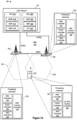
- the base station 104 is equipped with processing hardware 130 that can include one or more general-purpose processors (e.g., CPUs) and a non-transitory computer-readable memory storing instructions that the one or more general-purpose processors execute. Additionally or alternatively, the processing hardware 130 can include special-purpose processing units.
- the processing hardware 130 in an example implementation includes a Medium Access Control (MAC) controller 132 configured to perform a random access procedure with one or more user devices, receive uplink MAC protocol data units (PDUs) to one or more user devices, and transmit downlink MAC PDUs to one or more user devices.
- MAC Medium Access Control
- the processing hardware 130 can also include a Packet Data Convergence Protocol (PDCP) controller 134 configured to transmit PDCP PDUs in accordance with which the base station 104 can transmit data in the downlink direction, in some scenarios, and receive PDCP PDUs in accordance with which the base station 104 can receive data in the uplink direction, in other scenarios.
- the processing hardware further can include an RRC controller 136 to implement procedures and messaging at the RRC sublayer of the protocol communication stack.
- the processing hardware 130 in an example implementation includes an RRC inactive controller 138 configured to manage uplink and/or downlink communications with one or more UEs operating in the RRC_INACTIVE or RRC_IDLE state.
- the base station 106 can include generally similar components. In particular, components 140, 142, 144, 146, and 148 can be similar to the components 130, 132, 134, 136, and 138, respectively.
- the UE 102 is equipped with processing hardware 150 that can include one or more general-purpose processors such as CPUs and non-transitory computer-readable memory storing machine-readable instructions executable on the one or more general-purpose processors, and/or special-purpose processing units.
- the processing hardware 150 in an example implementation includes an RRC inactive controller 158 configured to manage uplink and/or downlink communications when the UE 102 operates in the RRC_INACTIVE state.
- the processing hardware 150 in an example implementation includes a Medium Access Control (MAC) controller 152 configured to perform a random access procedure with a base station, transmit uplink MAC protocol data units (PDUs) to the base station, and receive downlink MAC PDUs from the base station.
- MAC Medium Access Control
- the processing hardware 150 can also include a PDCP controller 154 configured to transmit PDCP PDUs in accordance with which the UE 102 can transmit data in the uplink direction, in some scenarios, and receive PDCP PDUs in accordance with which the UE 102 can receive data in the downlink direction, in other scenarios.
- the processing hardware further can include an RRC controller 156 to implement procedures and messaging at the RRC sublayer of the protocol communication stack.
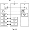
- Fig. 1B depicts an example, distributed or disaggregated implementation of any one or more of the base stations 104, 106.
- the base station includes a central unit (CU) 172 and one or more DUs 174.
- the CU 172 includes processing hardware, such as one or more general-purpose processors (e.g., CPUs) and a computer-readable memory storing machine-readable instructions executable on the general-purpose processor(s), and/or special-purpose processing units.
- the CU 172 can include a PDCP controller, an RRC controller and/or an RRC inactive controller such as PDCP controller 134, 144, RRC controller 136, 146 and/or RRC inactive controller 138, 148.
- the CU 172 can include a radio link control (RLC) controller configured to manage or control one or more RLC operations or procedures. In other implementations, the CU 172 does not include a RLC controller.
- RLC radio link control
- Each of the DUs 174 also includes processing hardware that can include one or more general-purpose processors (e.g., CPUs) and computer-readable memory storing machine-readable instructions executable on the one or more general-purpose processors, and/or special-purpose processing units.
- the processing hardware can include a MAC controller (e.g., MAC controller 132, 142) configured to manage or control one or more MAC operations or procedures (e.g., a random access procedure), and/or a RLC controller configured to manage or control one or more RLC operations or procedures.
- the processing hardware can also include a physical layer controller configured to manage or control one or more physical layer operations or procedures.
- the CU 172 includes a logical node CU-CP 172A that hosts the control plane part of the PDCP protocol of the CU 172.
- the CU 172 can also include logical node(s) CU-UP 172B that hosts the user plane part of the PDCP protocol and/or Service Data Adaptation Protocol (SDAP) protocol of the CU 172.
- SDAP Service Data Adaptation Protocol
- the CU-CP 172A can transmit control information (e.g., RRC messages, F1 application protocol messages), and the CU-UP 172B can transmit the data packets (e.g., SDAP PDUs or Internet Protocol packets).
- the CU-CP 172A can be connected to multiple CU-UP 172B through the E1 interface.
- the CU-CP 172A selects the appropriate CU-UP 172B for the requested services for the UE 102.
- a single CU-UP 172B can be connected to multiple CU-CP 172A through the E1 interface. If the CU-CP and DU(s) belong to a gNB, the CU-CP 172A can be connected to one or more DU 174s through an F1-C interface and/or an F1-U interface.
- the CU-CP 172A can be connected to one or more DU 174s through a W1-C interface and/or a W1-U interface.
- one DU 174 can be connected to multiple CU-UPs 172B under the control of the same CU-CP 172A.
- the connectivity between a CU-UP 172B and a DU 174 is established by the CU-CP 172A using Bearer Context Management functions.
- Fig. 2A illustrates, in a simplified manner, an example protocol stack 200 according to which the UE 102 can communicate with an eNB/ng-eNB or a gNB (e.g., one or more of the base stations 104, 106).
- an eNB/ng-eNB or a gNB e.g., one or more of the base stations 104, 106.
- Figs. 3A-5F the "inactive state” is used to represent the RRC_INACTIVE or RRC_IDLE state, unless otherwise noted.
- events in Figs. 3A-3B , Figs. 4A-4B , and 5A-5F that are the same are labeled with the same reference numbers (e.g., event 304 is the same in Figs. 3A-3B ), and events in Figs. 3A-5F that are similar are labeled with similar reference numbers (e.g., event 390A is similar to event 390B, 490, and 590.
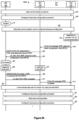
- the DU 174 can send 304 to the UE 102 second DCIs, each with a CRC scrambled with the first RNTI.
- the DU 174 includes a particular downlink (DL) assignment in each of the second DCIs.
- the DU 174 transmits 304 data to the UE 102 in accordance with the DL assignments.
- the DU 174 can generate the data or receive the data from the CU 172.
- the UE 102 performs a random access procedure with the DU 174.
- the DU 174 includes the first RNTI in a random access response or message B of the random access procedure.
- the DU 174 also sends a DU-to-CU message including the first RNTI to the CU 172.
- the UE 102 can receive the first RNTI in a handover command message (e.g., RRC reconfiguration message) from another base station (e.g., base station 106) directly or via a CN 110 (e.g., MME 114 or SMF 164).
- the first RNTI can be a C-RNTI.
- the CU 172 can determine that neither the CU 172 nor the UE 102 has transmitted any data in the downlink direction or the uplink direction, respectively, during the certain period. In some implementations, the CU 172 can make the determination based on a DU-to-CU message received from the DU 174 that indicates data inactivity of the UE 102. In response to the determination, the CU 172 performs 390A a configured resources configuration procedure. In the configured resources configuration procedure, the CU 172 sends 306 a CU-to-DU message to the DU 174 to obtain a configured grant (CG) configuration (e.g., encoded as an RRC IE).
- CG configured grant
- the CU-to-DU message that the CU 172 transmits may be a UE Context request message (e.g., a UE Context Setup Request message or a UE Context Modification Request message).
- the DU 174 assigns a second RNTI for the UE 102 and sends 308A to the CU 172 a DU-to-CU message including a CG configuration and the second RNTI.
- the DU-to-CU message may be a UE Context response message (e.g., a UE Context Setup Response message or a UE Context Modification Response message).
- the CG configuration indicates resources on which the UE 102 can transmit uplink transmissions to the DU 174 while operating in an inactive state (i.e., uplink resources for performing early data communication).
- the DU 174 can assign the second RNTI to the same value as the first RNTI.
- the DU 174 can assign the second RNTI to a value different from the value of the first RNTI.
- the CU 172 generates an RRC release message (e.g., RRCRelease message or RRCConnectionRelease message) to instruct the UE 102 to transition to the inactive state.
- the CU 172 includes the CG configuration and the second RNTI in the RRC release message.
- the DU 174 includes the CG configuration and the second RNTI in separate fields or IEs of the DU-to-CU message 308A.
- the DU 174 includes the second RNTI in the CG configuration and includes the CG configuration in a single field or IE of the DU-to-CU message 308A.
- the second RNTI included in the CG configuration can be transparent to the CU 172.
- the CU 172 needs to know the second RNTI.
- the CU 172 can decode the CG configuration to obtain the second RNTI.
- the DU 174 can include an additional instance of the second RNTI as an IE (e.g., F1AP IE or W1AP IE) of the DU-to-CU message 308A in addition to including the second RNTI in the CG configuration.
- the CU 172 can directly obtain the second RNTI from the IE of the DU-to-CU message 308A without decoding the CG configuration.
- the DU 174 can transmit to the UE 102 subsequent DCI(s), each with a CRC scrambled with the second RNTI, similar to event 318.
- the UE 102 can transmit a HARQ retransmission of the initial UL MAC PDU, similar to event 320.
- the DU 174 can decode a combination of the HARQ transmission and the HARQ retransmission(s) to obtain the initial UL MAC PDU.
- the UE 102 uses the second RNTI to generate a MAC-I instead of the first RNTI and includes the MAC-I in the UL RRC message.
- the CU 172 verifies the MAC-I based on the second RNTI when receiving 322 the UL RRC message. In this case, the UE 102 sets the source-c-RNTI to the value of the second RNTI.
- the DU 174 can establish or modify a UE context for the UE 102 and send a DU-to-CU message (e.g., a UE Context Setup Response message or a UE Context Modification Response message) to the CU 172 (not shown).
- a DU-to-CU message e.g., a UE Context Setup Response message or a UE Context Modification Response message
- the DU 174 includes a radio configuration for the UE 102 in the DU-to-CU message that the DU 174 transmits in response to receiving 324 the CU-to-DU message.
- the DU 174 may include an RNTI in the DU-to-CU message that the DU 174 transmits in response to receiving 324 the CU-to-DU message.
- the UE 102 can send subsequent UL MAC PDU(s) including subsequent UL data to the DU 174 on CG radio resources. For example, the UE 102 can send 328 (a HARQ transmission of) a subsequent UL MAC PDU including subsequent UL data to the DU 174 on CG radio resources. If the DU 174 fails to properly receive 328 the initial UL MAC PDU, the DU 174 can send 330 a DCI and a CRC scrambled with the second RNTI on a PDCCH to indicate the UE 102 to retransmit the subsequent UL MAC PDU similar to the earlier event 318.
- the DU 174 generates the DCI including a UL grant, generates a CRC from the DCI, and scrambles the CRC with the second RNTI.
- the UE 102 transmits 332 (a HARQ retransmission of) the subsequent UL MAC PDU. If the DU 174 fails to receive the subsequent UL MAC PDU from decoding a combination of the HARQ transmission and the HARQ retransmission, the DU 174 can transmit to the UE 102 subsequent DCI(s) each with a CRC scrambled with the second RNTI, similar to events 330.
- the UE 102 can transmit a HARQ retransmission of the subsequent UL MAC PDU, similar to event 332.
- the DU 174 can decode a combination of the HARQ transmission and the HARQ retransmission(s) to obtain the subsequent UL MAC PDU.
- the DU 174 can send 334 the UL data to the CU 172, e.g., via a control-plane interface (e.g., F1-C or W1-C) or a user-plane interface (e.g., F1-U or W1-U).
- the subsequent UL data includes PDCP PDU(s), RLC PDU(s), RRC PDU(s), NAS PDU(s), and/or IP packet(s).
- the RLC PDU(s) include RLC data PDU(s) and/or RLC control PDU(s).
- the subsequent UL data includes user-plane data and/or control-plane data.
- the user-plane data may include Internet of things (IoT) data, Ethernet traffic data, Internet traffic data, or a short message service (SMS) message.
- the control-plane data may include RRC message(s) and/or NAS message(s).
- the DU 174 can send 340 a DCI and a CRC scrambled with the second RNTI on a PDCCH to retransmit the DL MAC PDU. More specifically, the DU 174 generates the DCI including a DL assignment, generates a CRC from the DCI, and scrambles the CRC with the second RNTI. The DU 174 transmits 342 (a HARQ retransmission of) the DL MAC PDU on radio resources allocated in the DCI 340 (i.e., dynamic radio resources).
- the UE 102 If the UE 102 fails to receive the DL MAC PDU from decoding a combination of the HARQ transmission and the HARQ retransmission, the UE 102 transmits a HARQ NACK to the DU 174 (not shown), and the DU 174 can transmit to the UE 102 a subsequent DCI with a CRC scrambled with the second RNTI and transmit to the UE 102 (a HARQ retransmission of) the DL MAC PDU, similar to events 340 and 342. In accordance with or in response to each of the subsequent DCI(s), the UE 102 can receive a HARQ retransmission of the DL MAC PDU, similar to event 342.
- the UE 102 can decode a combination of the HARQ transmission and the HARQ retransmission(s) to obtain the DL MAC PDU. If the UE 102 receives the DL data, the UE 102 can send a HARQ acknowledgement (HARQ ACK) to the DU 174 (not shown).
- HARQ ACK HARQ acknowledgement
- the DL data includes PDCP PDU(s), RLC PDU(s), RRC PDU(s), NAS PDU(s), and/or IP packet(s).
- the DL PDU(s) include RLC data PDU(s) and/or RLC control PDU(s).
- the DU 174 can receive the DL data from the CU 172 and generates the RLC data PDU(s) or DL MAC PDU(s) to include the DL data.
- the DU 174 generates the RLC control PDU(s) (e.g., RLC Status PDU(s) to acknowledge or negatively acknowledge reception of a UL RLC PDU).
- the DL data includes user-plane data and/or control-plane data.
- the user-plane data may include Internet of things (IoT) data, Ethernet traffic data, Internet traffic data, or a short message service (SMS) message.
- the control-plane data may include RRC message(s) and/or NAS message(s).
- the DU 174 does not transmit an RNTI to the UE 102 via the CU 172 (i.e., via events 308A, 310A, 311A, and 312A).
- the DU 174 uses the first RNTI to scramble the CRCs in the events 320, 330, 336, 340 and the UE 102 uses the first RNTI to verify the CRCs in the events 320, 330, 336, 340.
- the CU 172 can assign an I-RNTI or a resume ID to the UE 102 and include the assigned value in the RRC release message.
- Fig. 3A The events 316, 318, 320, 322, 324, 328, 330, 332, 334, 336, 338, 340 and 342 are collectively referred to in Fig. 3A as an early data communication 392A.
- the CU 172 can perform 391A a configured resources configuration procedure with the UE 102 via the DU 174, similar to the configured resources configuration procedure 390A.
- the UE 102 stops performing early data communication with the base station 104. Later in time, the UE 102 can perform 393A a subsequent early data communication procedure via configured resources in a CG configuration received in the configured resources configuration procedure 391A, similar to the early data communication 392A.
- the CU 172 can perform 395A a configured resources configuration procedure with the UE 102 via the DU 174, similar to the configured resources configuration procedure 390A.
- a scenario 300B is similar to the scenario 300A, except that the DU 174 may transmit a semi-persistent scheduling (SPS) configuration to the CU 172 in addition to the CG configuration.
- SPS semi-persistent scheduling
- the DU 174 assigns a second RNTI for the UE 102 and sends 308B a DU-to-CU message to the CU 172.
- the DU 174 includes a CG configuration, an SPS configuration, and the second RNTI.
- the SPS configuration indicates resources on which the UE 102 can receive downlink transmissions from the DU 174 while operating in an inactive state (i.e., downlink resources for performing early data communication).
- the DU 174 can include an SPS configuration and the second RNTI in the CU-to-DU message and exclude a CG configuration from the CU-to-DU message.
- the DU 174 includes the CG configuration, the SPS configuration, and the second RNTI in separate fields or IEs of the DU-to-CU message 308B.
- the DU 174 includes the second RNTI in the CG configuration and the SPS configuration, and includes each of the CG configuration and the SPS configuration in separate fields or IEs of the DU-to-CU message 308B.
- the second RNTI included in the CG configuration and/or the SPS configuration can be transparent to the CU 172.
- the CU 172 can decode the CG configuration and/or the SPS configuration to obtain the second RNTI.
- the DU 174 can include an additional instance of the second RNTI as an IE (e.g., F1AP IE or W1AP IE) of the DU-to-CU message 308B in addition to including the second RNTI in the CG configuration and SPS configuration.
- the CU 172 can directly obtain the second RNTI from the IE of the DU-to-CU message 308B without decoding the CG configuration or SPS configuration.
- the CU 172 After receiving 310B the DU-to-CU message, the CU 172 generates an RRC release message including the CG configuration, the SPS configuration, and the second RNTI and transmits 310B a CU-to-DU message to the DU including the RRC release message.
- the DU 174 can then extract the RRC release message from the CU-to-DU message and transmit 312B the RRC release message to the UE 102.
- the UE 102 transitions to the inactive state upon receiving the RRC release message and operates 314 in the inactive state.
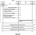
- a scenario 400A is similar to the scenario 300A, but where the UE 102 initially operates 414 in an inactive state rather than a connected state.
- the UE 102 performs 403 a random access procedure with the base station 104.
- the UE 102 initiates the random access procedure by transmitting 444 a random access preamble to the DU 174.
- the DU 174 generates a first RNTI for the UE 102 and includes the first RNTI in a random access response of the random access procedure.
- the DU 174 also sends 422 a DU-to-CU message including the first RNTI to the CU.
- the first RNTI can be a C-RNTI.
- the DU 174 transmits 446 the random access response including the first RNTI, a timing advance command, an ID of the random access preamble, and an uplink grant to the UE 102.
- the uplink grant indicates resources that the UE 102 can utilize to perform EDT with the DU 174 while operating 414 in the inactive state.
- the UE 102 transmits 416 an UL MAC PDU including an UL RRC message on resources configured by the uplink grant.
- the UE 102 can also include an uplink data packet in the UL MAC PDU.
- the DU 174 can transmit a contention resolution to the UE 102 to complete the random access procedure 403 (not shown). If the DU 174 fails to receive the UL MAC PDU in accordance with the UL grant, the DU 174 can send 418 a DCI and a CRC scrambled with the first RNTI on a PDCCH to indicate to the UE 102 to retransmit the UL MAC PDU. The UE 102 can then retransmit 420 the UL MAC PDU including the UL RRC message to the DU 174.
- the random access procedure that the UE 102 performs 403 is a four-step random access procedure, where the four steps of the random access procedure correspond to events 444, 446, 416, and the transmission of the contention resolution to the UE 102.
- Fig. 4B illustrates a scenario 400B, which is similar to the scenario 400A, except that that the UE 102 performs 405 a two-step random access procedure with the base station 104 to transmit data while operating 414 in the inactive state
- the UE 102 transmits 444 a random access preamble to the DU 174 and transmits 416 an UL MAC PDU including an UL RRC message to the DU 174.
- the UL MAC PDU may also include an UL data packet.
- the UE 102 may receive the random access preamble in an RRC message that causes the UE to transition to the inactive state.
- the DU 174 broadcasts a system information block (SIB) on the cell 124.
- SIB includes configuration(s) for the UE 102 to perform a two-step random access procedure on the cell 124.
- the UE 102 receives the SIB and transmits 416 an initial UL MAC PDU on radio resources indicated by the configuration(s).
- the events 444 and 416 may collectively be referred to as a "Message A" of the two-step random access procedure.
- the random access preamble and the payload are two parts of the Message A that are sent at different occasions.
- the UE 102 can transmit 444 the random access preamble via a Physical Random Access Channel (PRACH) occasion, and transmit 416 the payload via a Physical Uplink Shared Channel (PUSCH) occasion.
- PRACH Physical Random Access Channel
- PUSCH Physical Uplink Shared Channel
- the DU 174 transmits 447 a "Message B" including a first RNTI, to the UE 102.
- the Message B may include a successRAR MAC subheader and a successRAR MAC subPDUa, which indicates that the DU 174 successfully received the UL MAC PDU 416.
- the successRAR MAC subPDU includes a contention resolution identity, timing advance command, and the first RNTI.
- the successRAR MAC subPDU can further include PUCCH Resource Indicator, HARQ Feedback Timing Indicator, Transmit Power Control (TPC) command, and/or channel access type and CP extension.
- TPC Transmit Power Control
- the Message B may include a fallbackRAR MAC subheader and a fallbackRAR MAC subPDU, which indicates to the UE 102 to retransmit the UL MAC PDU that the UE 102 transmits at event 416.
- the fallbackRAR MAC subPDU includes a UL grant, timing advance command, the first RNTI.
- the UE 102 retransmits 448 the UL MAC PDU to the DU 174 in accordance with the UL grant. If the DU 174 successfully receives 448 the UL MAC PDU, the DU 174 can send a contention resolution to the UE 102 to complete the random access procedure.
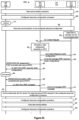
- a scenario 500A begins similarly to any one of the scenarios 300A-B or 400A-B, but the CU 172 determines to transition the UE 102 to the connected state.
- the UE 102 performs 504 a data communication procedure with the base station 104.
- the data communication procedure 504 can be similar to event 304 (i.e., the UE 102 can initially operate in the connected state), or random access procedure 403 or 405 (i.e., the UE 102 can initially operate in the inactive state and perform a random access procedure to communicate with the base station 104 while operating in the inactive state).
- the CU 172 determines 550 to transition the UE 102 to the connected state.
- the CU 172 sends 558 a CU-to-DU message to the DU 174 including an RRC response message (e.g., an RRC setup message or an RRC resume message).
- the CU 172 includes a radio configuration for the UE 102 and a third RNTI.
- the radio configuration is a configuration that the UE 102 can use to communicate with the DU 174 after transitioning to the connected state.
- the CU 172 may receive the radio configuration and the third RNTI from the DU 174 during the early data communication procedure 592.
- the CU 172 may receive the radio configuration and the third RNTI from the DU 174 in a DU-to-CU message that the DU 174 transmits to the CU 172 during the early data communication procedure (e.g., at an event during the early data communication procedure 592 similar to event 322 or the DU-to-CU message that the DU 174 transmits in response to receiving 324 the CU-to-DU message).
- the early data communication procedure e.g., at an event during the early data communication procedure 592 similar to event 322 or the DU-to-CU message that the DU 174 transmits in response to receiving 324 the CU-to-DU message.
- the DU 174 may transmit 560 a DCI and a CRC scrambled with the second RNTI (i.e., the RNTI the DU 174 assigns to the UE 102 during the configured resources configuration procedure 590) on a PDCCH.
- the DCI indicates a DL assignment on which the UE 102 can receive 562 a DL MAC PDU.
- the DU 174 may refrain from transmitting 560 the DCI.
- the DU 174 still transmits 560 the DCI even though the UE 102 obtains the SPS configuration.
- the DU 174 may do so because there is no SPS radio resource available for transmission at a particular time slot where the DU 174 determines to transmit 562 the RRC response message.
- the DU 174 then sends 562 a DL MAC PDU to the UE 102, where the DL MAC PDU includes the RRC response message that the DU 174 received 558 from the CU 172.
- the UE 102 transitions 564 to the connected state (e.g., RRC_CONNECTED) and applies 566 the third RNTI.
- the DU 174 also applies 567 the third RNTI.
- the CU 102 includes a reconfiguration with sync indication (e.g., a ReconfigurationWithSync IE) in the RRC response message.
- the reconfiguration with sync indication causes the UE 102 to perform a random access procedure with the UE 102, during which the UE 102 and the DU 174 can apply 566, 567 the third RNTI.
- the reconfiguration with sync indication is further discussed with reference to Fig. 13 .
- the UE 102 and the DU 174 can release or discard the second RNTI.
- the UE 102 and the DU 174 also release or discard the first RNTI.
- the UE 102 can then communicate with the DU 174, and with the CU 172 via the DU 174, using the third RNTI.
- the DU 174 for example, can transmit DCIs to the UE 102 with CRCs scrambled using the third RNTI.
- the UE 102 can transmit an RRC reestablishment request message to the CU 172 via the DU 174.
- the RRC reestablishment request message includes a MAC-I that the UE 102 generates based on the third RNTI, and the CU 172 can therefore determine whether the RRC reestablishment request is valid by verifying the MAC-I using the third RNTI.
- the CU 172 can send an RRC reestablishment message to the UE 102 via the DU 174 in response to the RRC reestablishment request message. Otherwise, the CU 172 can send an RRC setup message or an RRC reject message to the UE 102 in response to the RRC reestablishment request message.
- the CU 172 may determine to transition the UE 102 to an inactive state and configure resources for the UE 102 to utilize while operating in the inactive state. Accordingly, the CU 172 may initiate a configured resources configuration procedure 591, in which the DU 174 can assign another RNTI for the UE 102. The UE 102 can then perform 593 early data communication with the base station 104 using a configured resources configuration obtained during the configured resources configuration procedure 591. Similar to Fig. 3A , this process of configured resources configuration procedure followed by early data communication may continue with a configured resources configuration 595 following early data communication 593.
- Fig. 5B illustrates a scenario 500B that is similar to the scenario 500A.
- the CU 172 transmits 552 a UE Context Request message (e.g., a UE Context Setup Request message or a UE Context Modification Request message) to the DU 174.
- the DU 174 generates a radio configuration including a fourth RNTI for the UE 102.
- the DU 174 transmits 556 a UE Context Response message (e.g., a UE Context Setup Response message or a UE Context Modification Response message) including the radio configuration to the CU 172.
- the DU 174 also includes the fourth RNTI as a field or IE of the UE Context Response message to inform the CU 172 of the fourth RNTI.
- the UE 102 After receiving 562 the RRC response message and transitioning 564 to the connected state, the UE 102 utilizes the second RNTI (i.e., the RNTI that the UE 102 received during the configured resources configuration procedure 590) because the radio configuration does not include a new RNTI for the UE 102 to utilize.
- the DU 174 also continues to use the second RNTI. Accordingly, the DU 174 may send 569 a DCI and a CRC scrambled using the second RNTI to the UE 102, where the DCI indicates an UL grant for the UE to use to transmit 570 an RRC complete message.
- the UE 102 can then communicate 575 with the DU 174, and with the CU 172 via the DU 174, using the second RNTI.
- the UE 102 can transmit an RRC reestablishment request to the CU 172 via the DU 174.
- the RRC reestablishment request includes a MAC-I that the UE 102 generates based on the second RNTI.
- the CU 172 verifies the MAC-I based on the second RNTI.
- the RRC reestablishment request includes a MAC-I that the UE 102 generates based on the first RNTI.
- the CU 172 verifies whether the MAC-I is valid based on the first RNTI.
- a scenario 500D is initially similar to the scenarios 500A-500C. However, after or during the early data communication 592, the CU 172 transmits 559 an RRC reject message to the DU 174, which in turn transmits 563 the RRC reject message to the UE 102. In some implementations, the CU 172 determines to send the RRC reject message to the UE 102 because the CU 172 or the DU 174 is congested. In such cases, the CU 172 can include a wait time in the RRC reject message.
- the UE 102 is not allowed to access the DU 174 (e.g., not allowed to perform subsequent early data communication or to perform an RRC resume or setup procedure with the CU 172 via the DU 174) before the wait time elapses.
- the UE can perform 594 subsequent early data communication after the wait time elapses.
- the UE 102 may use the configured resources configuration received during event 590.
- the UE 102 may retain the first RNTI.
- the UE 102 can use the first RNTI, for example, to generate a MAC-I included in an UL RRC message during the subsequent early data communication 594.
- the UE 102 may also retain the second RNTI, which the UE 102 can use to descramble CRCs received from the DU 174 during the subsequent early data communication 594.
- a scenario 500E is initially similar to the scenario 500D.
- the UE 102 releases the configured resources configuration(s) that the UE 102 received during event 590.
- the UE 102 may retain the first and/or second RNTIs, as discussed above with reference to Fig. 5D .
- the UE 102 can perform 503 a data communication procedure, which may be the random access procedure 403 or 405.
- the UE 102 receives a new RNTI (e.g., similar to the first RNTI) with which the UE 102 can communicate with the DU 174 and the CU 172.
- the DU 174 can also assign another RNTI (e.g., similar to the second RNTI) to the UE 102 during a configured resources configuration procedure 591. Alternatively, the UE 102 may release or discard the second RNTI in response to receiving 563 the RRC reject message.
- the CU 172 can send a CU-to-DU message to the DU 174 to release the second RNTI and/or the configured resources configuration in response to the determination to send the RRC reject message.
- the CU 172 can indicate whether the UE 102 retains or releases/discards the second RNTI in the RRC reject message.
- the UE 102 retains or releases/discards the second RNTI in accordance with the indication in the RRC reject message.
- the CU 172 can include an indication in the RRC reject message to indicate the UE 102 to retain the second RNTI and the configured resources configuration.
- the UE 102 retains the second RNTI and the configured resources configuration. If the RRC reject message does not include the indication, the UE 102 can release the second RNTI and the configured resources configuration.
- a scenario 500F is initially similar to the scenarios 500D and 500E.
- inactive state has been used to represent either RRC_INACTIVE or RRC_IDLE.
- references to the inactive state refer to RRC_INACTIVE
- references to the idle state refer to RRC_IDLE.
- the UE 102 releases the first RNTI and releases 576 the configured resources configuration(s) that the UE 102 received during event 590.
- the UE 102 also may release the second RNTI that the UE received during event 590.
- the CU 172 transmits 559 the RRC reject message to the UE 102 because the CU 172 or the DU 174 is congested.
- the CU 172 can include a wait time in the RRC reject message.
- the UE 102 can attempt to perform subsequent early data communication with the base station 104 after the wait time elapses.
- the CU 172 transmits 559 the RRC reject message to the UE 102 via the DU 174 because the CU 172 detects a failure or an error during the early data communication. In such cases, the UE 102 may be unable to perform subsequent early data communication, and may utilize the techniques illustrated in Fig. 5F .
- the UE 102 After releasing 576 the configured resources configuration(s), the UE 102 initiates an RRC setup procedure. In particular, the UE 102 performs 505 an RRC setup request transmission procedure.
- the RRC setup request transmission procedure 505 may be similar to the random access procedure 403 or 405.
- the UL RRC message that the UE 102 transmits to the DU 174 during the random access procedure may be an RRC setup request message.
- the DU 174 assigns a third RNTI to the UE 102, similar to how the DU 174 assigns the first RNTI to the UE 102 during the random access procedures 403 and 405.
- the CU 172 then transmits an RRC setup message to the UE 102 via the DU 174.
- the DU 174 can transmit 576 a DCI and a CRC scrambled using the third RNTI to the UE 102, where the DCI indicates resources on which the UE 102 can receive the RRC setup message.
- the UE 102 transitions 564 to the connected state and transmits 582 an RRC complete message to the CU 172 via the DU 174.
- the DU 174 may indicate resources on which the UE 102 can transmit the RRC complete message by transmitting a DCI and a CRC scrambled using the third RNTI.
- the UE 102 can then communicate 586 with the DU 174 and/or the CU 172 using the third RNTI.
- a DU (e.g., the DU 174) can implement an example method 600A to communicate with a UE (e.g., the UE 102) while the UE operates in an inactive state.
- the DU communicates data with the UE using a first RNTI, and communicates the data with a CU (e.g., the CU 172) (e.g., events 304, 403, 405).
- the first RNTI can be, for example, a C-RNTI or a CS-RNTI.
- the UE may be operating in the inactive state at block 602 (e.g., as in Figs. 4A-4B ), or the UE may be operating in the connected state at block 602 (e.g., as in Figs. 3A-3B ).
- the DU generates at least one configured resources configuration and a second RNTI for the UE.
- the at least one configured resources configuration includes CG configuration(s) for UL data transmission and/or includes SPS configuration(s) for DL data reception
- the DU generates the at least one configured resources configuration specifically for the UE to use to communicate with the DU while the UE operates in the inactive state. If the UE later transitions to the connected state, the DU stops using the at least one configured resources configuration. In other implementations, the DU continues to use the at least one configured resources configuration when or after the UE transitions to the connected state.
- the DU sends the at least one configured resources configuration and the second RNTI to the UE via the CU (e.g., events 308A, 310A, 311A, 312A, 308B, 310B, 311B, 312B, 490, 590).
- the DU sends a CU-to-DU message to the CU including the at least one configured resources configuration and the second RNTI, and the CU sends the at least one configured resources configuration and the second RNTI to the UE via the DU 174.
- the CU can transmit to the DU a DL RRC message including the at least one configured resources configuration and the second RNTI, and the DU can transmit the DL RRC message to the UE.
- the CU generates an additional RNTI (e.g., an inactive RNTI (I-RNTI)) or a resume identity and includes the additional RNTI or resume identity in the DL RRC message.
- the DL RRC message can be, for example, an RRC release message. If the UE operates in the connected state at block 602, the DL RRC message causes the UE to transition to the inactive state.
- the DU includes the second RNTI in at least one of the at least one configured resources configuration.
- the DU generates a container IE including the at least one configured resources configuration and the second RNTI and sends the container IE to the UE via the CU.
- the container IE can be a CellGroupConfig IE or an existing IE in a CellGroupConfig IE.
- the container IE can be a newly defined IE.
- the data includes a UL RRC message and/or a PDCP PDU.
- the DU can include the UL RRC message in the first/second DU-to-CU message.
- the DU can include the PDCP PDU in the first/second DU-to-CU message.
- the DU does not include the PDCP PDU in the first/second DU-to-CU message and sends the PDCP PDU separately on a DU-to-CU user plane interface (e.g., F1-U or W1-U).
- Fig. 10 is a flow diagram of an example method 1000 for configuring a UE (e.g., the UE 102) with configured resources while the UE operates in an inactive state, which can be implemented by a CU (e.g., the CU 172).
- the CU communicates data with a UE operating in an inactive state via a DU (e.g., the DU 174).
- the CU determines to configure configured resources (e.g., a CG configuration or an SPS configuration) for the UE to use while operating in the inactive state.
- configured resources e.g., a CG configuration or an SPS configuration
- the CU performs a UE Context procedure with the DU to obtain at least one configured resources configuration, at block 1006 (e.g., during events 391, 490, 491).
- the UE Context procedure is a UE Context Setup procedure.
- the UE Context procedure is a UE Context Modification procedure.
- the CU includes the at least one configured resources configuration in an RRC release message, which the CU sends to the UE via the DU at block 1010 (e.g., during events 391, 490, 491). If the CU determines at block 1004 not to configure configured resources for the UE, then the flow proceeds directly to block 1010 from block 1004.
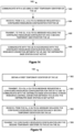
- Fig. 11 is a flow diagram of an example method 1100 for processing an RNTI based on whether a UE (e.g., the UE 102) is transitioning to a connected state, which can be implemented by a CU (e.g., the CU 172).
- the CU receives, from a DU (e.g., the DU 174), a first RNTI and a second RNTI for a UE, where the UE is operating in an inactive state.
- a DU e.g., the DU 174
- the first RNTI may be an RNTI that CU previously used to communicate with the UE while the UE operated in the connected state (e.g., the first RNTI from event 304), or an RNTI that the CU received from a DU during a random access procedure with the UE operating in the inactive state (e.g., the first RNTI from events 403, 405).
- the second RNTI may be an RNTI that the CU received with a configured resources configuration from a DU (e.g., the second RNTI from Figs. 3A-4B ).
- the CU receives, from the UE via the DU, a UL message including a MAC-I.
- the UL message can be an UL RRC message.
- the CU uses the first RNTI to verify whether the MAC-I received at block 1104 is valid.
- the CU determines whether to transition the UE from the inactive state to a connected state. If the CU determines to transition the UE to the connected state, then the flow proceeds to block 1110.
- the CU discards the first RNTI (e.g., because the CU determines that the first RNTI will no longer be valid after the UE transitions to the connected state).
- the CU transmits a first DL message to the UE via the DU in order to transition the UE to the connected state. If the CU determines not to transition the UE to the connected state, then the flow proceeds to block 1114.
- the CU retains the first RNTI (e.g., because the CU determines that the first RNTI is still valid for the UE while the UE remains in the inactive state).
- the CU transmits a second DL message to the UE via the DU to keep the UE in the inactive state.
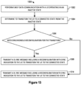
- the UE receives a DCI and a CRC from the RAN.
- the UE determines whether the UE is operating in a connected state or an inactive state. If the UE is operating in a connected state, then the UE uses the first and second RNTIs, respectively, to process the CRC, at block 1210. If the UE is operating in the inactive state, then the UE uses the second RNTI to process the CRC and refrains from using the first RNTI to process the CRC.
- the UE in Fig. 12 processes the CRC to identify whether the DCI is addressed to the UE.
- the UE processes a CRC by using an RNTI to descramble the CRC.
- the UE also calculates a CRC from the DCI. If the calculated CRC is the same as the descrambled CRC, the UE determines that the DCI is addressed to the UE.
- the UE processes a CRC by using an RNTI to scramble a CRC calculated from the DCI. If the scrambled, calculated CRC is the same as the received CRC, the UE determines that the DCI is addressed to the UE.
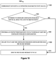
- Fig. 13 is a flow diagram of an example method 1300 for determining whether to include a reconfiguration with sync indication in a message instructing a UE (e.g., the UE 102) to transition to an inactive state, which can be implemented by a RAN node, such as a CU (e.g., the CU 172) or a base station (e.g., the base station 104).
- a RAN node such as a CU (e.g., the CU 172) or a base station (e.g., the base station 104).
- the RAN node performs early data communication with the UE while the UE operates in an inactive state.
- the RAN node determines to transition the UE from the inactive state to a connected state.
- the RAN node determines whether synchronous reconfiguration is needed for the transition. In some implementations, the RAN node determines that synchronous reconfiguration is needed for the transition because the RAN node is reconfiguring the UE to use a second RNTI in the connected state instead of a first RNTI that the UE used during the early data communication while operating in the inactive state (e.g., as in the scenarios 500A and 500B in which the base station 104 configures the UE 102 to use a third RNTI or a fourth RNTI, respectively, instead of the second RNTI after transitioning to the connected state).
- the RAN node determines that synchronous reconfiguration is needed for the transition because the RAN node is reconfiguring the UE to use a second RNTI in the connected state instead of a first RNTI that the UE used during the early data communication while operating in the inactive state (e.g., as in the scenarios 500A and 500B in which the base station 104 configures the UE 102 to use a third
- the RAN node determines synchronous reconfiguration is needed for the transition because the RAN node is reconfiguring the UE to reestablish PDCP and/or RLC entity/entities for the transition. That is, the UE in the connected state uses the reestablished entity/entities to communicate with the RAN node. In yet other implementations, the RAN node determines synchronous reconfiguration is needed for the transition because the RAN node is reconfiguring the UE to derive new security key(s) for communication in the connected state.
- the RAN node determines that synchronous reconfiguration is needed for the transition, then the RAN node transmits, at block 1308, a DL RRC message including a reconfiguration with sync indication (e.g., a ReconfigurationWithSync IE) to the UE to transition the UE to the connected state. Otherwise, the RAN node transmits, at block 1314, a DL RRC message excluding a reconfiguration with sync indication to the UE to transition the UE to the connected state.
- a DL RRC message including a reconfiguration with sync indication (e.g., a ReconfigurationWithSync IE)
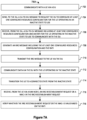
- Fig. 14 is a flow diagram of an example method 1400 for managing early data communication with a UE (e.g., the UE 102), which can be performed by a DU (e.g., the DU 174) of a distributed base station.
- the DU communicates with the UE using a first temporary identifier (e.g., a first RNTI) of the UE (e.g., events 304, 403, 405, 504).
- the DU receives, from a CU (e.g., the CU 172) of the distributed base station, a CU-to-DU message requesting a configured resources configuration for the UE (e.g., events 306, 490, 590).
- a CU e.g., the CU 172
- a CU-to-DU message requesting a configured resources configuration for the UE (e.g., events 306, 490, 590).
- the DU communicates with the UE in accordance with the configured resources configuration while a radio resource control connection between the UE and the distributed base station is not active (e.g., while the UE operates in an inactive or an idle state, such as RRC_INACTIVE or RRC_IDLE) (e.g., events 392A, 392B, 492, 592).
- a radio resource control connection between the UE and the distributed base station is not active (e.g., while the UE operates in an inactive or an idle state, such as RRC_INACTIVE or RRC_IDLE) (e.g., events 392A, 392B, 492, 592).
- communicating with the UE using the first temporary identifier includes communicating with the UE using the first temporary identifier while the UE operates in the connected state (e.g., event 304).
- the DU may assign the first temporary identifier to the UE while a radio resource control connection with the UE is not active.
- the DU-to-CU message is a second DU-to-CU message, and communicating with the UE using the first temporary identifier includes, prior to receiving the CU-to-DU message, performing a random access procedure with the UE while the radio resource control connection is not active and without transitioning the UE to a connected state (e.g., event 403, 405).
- Performing the random access procedure includes assigning the first temporary identifier to the UE (e.g., events 446, 447) and receiving, from the UE, a message formatted in accordance with a protocol for controlling radio resources (e.g., event 416).
- Performing the random access procedure may include performing a four-step random access procedure (e.g., event 403), or a two-step random access procedure (e.g., event 405).
- the DU-to-CU message is a first DU-to-CU message
- the method 1400 further includes: transmitting, to the CU, a second DU-to-CU message including a configuration and a third temporary identifier for the UE (e.g., event 322, event 592, 556), and communicating with the UE using the third temporary identifier while the UE operates in a connected state (e.g., event 574).
- the CU-to-DU message may be a first CU-to-DU message
- the method may further include receiving, from the CU, a second CU-to-DU message requesting the configuration for the UE to use to communicate with the distributed base station (e.g., event 552), where the DU transmits the second DU-to-CU message to the CU in response to the second CU-to-DU message.
- the distributed base station e.g., event 552
- the method 1400 may further include receiving, from the CU, a command for the UE to transition to the connected state, the command including the configuration and the third temporary identifier, and transmitting the command to the UE (e.g., events 558, 560), where the DU communicates with the UE using the third temporary identifier subsequently to transmitting the command.
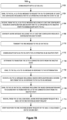
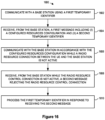
- Fig. 15 is a flow diagram of an example method 1500 for managing early data communication with a UE (e.g., the UE 102), which can be performed by a CU (e.g., the CU 172) of a distributed base station.
- the CU obtains a first temporary identifier of the UE (e.g., events 304, 422, 504).
- the CU transmits, to a DU (e.g., the DU 174) of the distributed base station, a CU-to-DU message requesting a configured resources configuration for the UE to use to communicate with the distributed base station while a radio resource control connection between the UE and the distributed base station is not active (e.g., events 306, 490, 590).
- the CU receives, from the DU, a DU-to-CU message including the configured resources configuration and a second temporary identifier for the UE (e.g., events 308A, 308B, 490, 590).
- the CU transmits the configured resources configuration and the second temporary identifier to the UE via the DU (e.g., events 310A, 310B, 490, 590).
- the CU may include the configured resources configuration and the second temporary identifier in a message formatted in accordance with a protocol for controlling radio resources, and transmit the message to the UE via the DU.
- the message may instruct the UE to transition from a connected state to an inactive or an idle state.
- the CU may, prior to transmitting the CU-to-DU message, communicate with the UE using the first temporary identifier while the UE operates in a connected state (e.g., event 304). While the radio resource control connection with the UE is not active, the CU may receive, from the UE via the DU, an uplink message, such as an UL RRC message, including an authentication code (e.g., a MAC-I) (e.g., event 322). The CU may verify the authentication code using the first temporary identifier. In some implementations, at a later time, the CU may transmit a message rejecting the radio resource control connection (e.g., an RRC reject message) (e.g., event 559). After transmitting the message, the CU may receive, from the UE via the DU, a second uplink message including a second authentication code, and the CU may verify the second authentication code using the first temporary identifier.
- an uplink message such as an UL RRC message
- an authentication code
- the CU may obtain the first temporary identifier from the DU while the UE operates in the inactive state.
- the DU-to-CU message may be a second DU-to-CU message, and obtaining the first temporary identifier may include: prior to transmitting the CU-to-DU message, receiving a first DU-to-CU message including a message formatted in accordance with a protocol for controlling radio resources and the first temporary identifier (e.g., event 422).
- the CU may transmit the CU-to-DU message in response to receiving the first DU-to-CU message.
- the CU may determine to transition the UE to a connected state. In such implementations, the CU may determine to discard the first temporary identifier (e.g., block 1110). Further, in such implementations, the CU may receive a second DU-to-CU message including a configuration and a third temporary identifier for the UE (e.g., event 322, 592, 556). The CU can transmit, to the DU, a command for the UE to transition to the connected state, the command including the configuration and the third temporary identifier (e.g., event 558). The CU can then communicate with the UE via the DU using the third temporary identifier while the UE operates in the connected state (e.g., event 574).
- a second DU-to-CU message including a configuration and a third temporary identifier for the UE (e.g., event 322, 592, 556).
- the CU can transmit, to the DU, a command for the UE to transition to the connected state,
- the CU communicates with the UE via the DU while the radio resource control connection is not active, and transmits, to the UE via the DU, a command instructing the UE to transition to a connected state (e.g., event 558).
- the CU may receive, from the UE via the DU, a request to reestablish the radio resource control connection (e.g., an RRC reestablishment request message) including an authentication code.
- the CU may use the second temporary identifier to verify the authentication code, or may use a temporary identifier that the CU sends to the UE when transitioning the UE to the connected state, depending on the implementation.
- the CU may verify the authentication code using the third temporary identifier. Further, the CU may include in the command an indication that the UE is to perform a reconfiguration with sync (e.g., a reconfiguration with sync indication, such as a ReconfigurationWithSync IE).
- a reconfiguration with sync indication such as a ReconfigurationWithSync IE
- Fig. 16 is a flow diagram of a complementary method 1600 for managing communications with a base station (e.g., the base station 104), which can be performed by a UE (e.g., the UE 102).
- the UE communicates with the base station using a first temporary identifier (e.g., event 504).
- the UE receives, from the base station, a first message including (i) a configured resources configuration and (ii) a second temporary identifier (e.g., event 590).
- the UE communicates with the base station in accordance with the configured resources configuration while a radio connection between the UE and the base station is not active (e.g., event 592).
- the UE receives, from the base station while the radio resource control connection is not active, a second message rejecting the radio resource control connection (e.g., event 563).
- the UE processes the first temporary identifier in response to receiving the second message.
- the radio connection can be a RRC connection.
- processing the first temporary identifier includes retaining the first temporary identifier (e.g., scenarios 500D-500E).
- the UE may utilize the retained first temporary identifier to communicate with the base station in accordance with the configured resources configuration (e.g., event 594).
- the UE may release the configured resources configuration (e.g., event 576).
- processing the first temporary identifier includes releasing the first temporary identifier (e.g., scenario 500F).
- the UE may operate in an inactive state (e.g., RRC_INACTIVE) while the radio resource control connection is not active, and, in response to receiving the second message: transition to an idle state (e.g., RRC_IDLE) (e.g., event 565), and release the configured resources configuration (e.g., event 576).
- the UE may transmit, to the base station, a request to set up a radio resources control connection with the base station (e.g., an RRC setup request message) (e.g., event 505).
- the UE may receive a third temporary identifier from the base station.
- the UE may then transition to a connected state (e.g., event 564) and communicate with the base station using the third temporary identifier (e.g., event 586).
- “message” is used and can be replaced by “information element (IE)”.
- “IE” is used and can be replaced by "field”.
- “configuration” can be replaced by “configurations” or the configuration parameters.
- a user device in which the techniques of this disclosure can be implemented can be any suitable device capable of wireless communications such as a smartphone, a tablet computer, a laptop computer, a mobile gaming console, a point-of-sale (POS) terminal, a health monitoring device, a drone, a camera, a media-streaming dongle or another personal media device, a wearable device such as a smartwatch, a wireless hotspot, a femtocell, or a broadband router.
- the user device in some cases may be embedded in an electronic system such as the head unit of a vehicle or an advanced driver assistance system (ADAS).
- ADAS advanced driver assistance system
- the user device can operate as an internet-of-things (IoT) device or a mobile-internet device (MID).
- IoT internet-of-things
- MID mobile-internet device
- the user device can include one or more general-purpose processors, a computer-readable memory, a user interface, one or more network interfaces, one or more sensors, etc.
- Modules may can be software modules (e.g., code, or machine-readable instructions stored on non-transitory machine-readable medium) or hardware modules.
- a hardware module is a tangible unit capable of performing certain operations and may be configured or arranged in a certain manner.
- a hardware module can comprise dedicated circuitry or logic that is permanently configured (e.g., as a special-purpose processor, such as a field programmable gate array (FPGA) or an application-specific integrated circuit (ASIC), a digital signal processor (DSP), etc.) to perform certain operations.
- FPGA field programmable gate array
- ASIC application-specific integrated circuit
- DSP digital signal processor
- a hardware module may also comprise programmable logic or circuitry (e.g., as encompassed within a general-purpose processor or other programmable processor) that is temporarily configured by software to perform certain operations.
- programmable logic or circuitry e.g., as encompassed within a general-purpose processor or other programmable processor
- the decision to implement a hardware module in dedicated and permanently configured circuitry, or in temporarily configured circuitry (e.g., configured by software) may be driven by cost and time considerations.
Landscapes
- Engineering & Computer Science (AREA)
- Computer Networks & Wireless Communication (AREA)
- Signal Processing (AREA)
- Mobile Radio Communication Systems (AREA)
Claims (15)
- Verfahren in einer verteilten Einheit (distributed unit, DU) einer verteilten Basisstation, wobei die verteilte Basisstation die DU und eine Zentraleinheit (central unit, CU) zum Verwalten früher Datenkommunikation mit einem Endgerät (user equipment, UE) beinhaltet, wobei das Verfahren Folgendes umfasst:Kommunizieren (1402; 304; 403; 405; 504), mit der DU (102) unter Verwendung eines temporären Bezeichners des UE durch die DU (174); gekennzeichnet durch ferner Umfassen vonEmpfangen (1404; 306; 490; 590) einer ersten CU-zu-DU-Nachricht, die eine dazu konfigurierte Ressourcenkonfiguration für das UE anfordert, von der CU (172);Übertragen (1406; 308A; 308B; 490; 590) einer DU-zu-CU-Nachricht, die die dazu konfigurierte Ressourcenkonfiguration für das UE (102) beinhaltet, an die CU (172);Empfangen (310A; 310B) einer zweiten CU-zu-DU-Nachricht, die eine Nachricht beinhaltet, die die konfigurierte Ressourcenkonfiguration und einen konfigurierten Planungs-RNTI, CS-RNTI, beinhaltet und Freigeben einer Funkressourcensteuerungsverbindung angibt, von der CU (172);Extrahieren der Nachricht aus der zweiten CU-zu-DU-Nachricht; und Übertragen (311 A; 311B; 312A; 312B) der Nachricht an das UE (102); Kommunizieren (1408; 392A, 392B; 492; 592) mit dem UE (102) gemäß der konfigurierten Ressourcenkonfiguration, während die Funkressourcensteuerungsverbindung zwischen dem UE (102) und der verteilten Basisstation nicht aktiv ist.
- Verfahren nach Anspruch 1, wobei der CS-RNTI in der DU-zu-CU-Nachricht in mindestens einem von Folgendem beinhaltet ist:einem Informationselement, das durch ein Protokoll definiert ist, dem Signalisieren zwischen der CU (172) und der DU (174) entspricht; oderder konfigurierten Ressourcenkonfiguration.
- Verfahren nach einem der vorhergehenden Ansprüche, ferner umfassend:Erzeugen einer Downlink-Steuerungsinformation (downlink control information, DCI), die die Ressourcen angibt, auf denen das UE (102) eine Uplink-Übertragung an das DU (174) übertragen soll, während die Funkressourcensteuerungsverbindung nicht aktiv ist; Verschlüsseln eines zyklischen Redundanzprüfungswerts (cyclic redundancy check, CRC) für den DCI unter Verwendung des zweiten temporären Bezeichners; undÜbertragen (318; 330) des DCI- und des CRC-Werts an das UE (102), während die Funkressourcensteuerungsverbindung nicht aktiv ist.
- Verfahren nach Anspruch 3, wobei:die DU (174) den DCI als Reaktion auf das fehlerhafte Empfangen einer geplanten Übertragung von dem UE (102) gemäß der konfigurierten Ressourcenkonfiguration überträgt; undder DCI eine Wiederübertragung der geplanten Übertragung plant.
- Verfahren nach Anspruch 1 oder 2, ferner umfassend:Erzeugen einer DCI, die die Ressourcen angibt, auf denen das UE eine Downlink-Übertragung an das DU (174) empfangen soll, während die Funkressourcensteuerungsverbindung nicht aktiv ist;Verschlüsseln eines zyklischen CRC-Werts für den DCI unter Verwendung des zweiten temporären Bezeichners; undÜbertragen (318; 330) des DCI- und des CRC-Werts an das UE (102), während die Funkressourcensteuerungsverbindung nicht aktiv ist.
- Verfahren nach Anspruch 1 oder 2, ferner umfassend:Erzeugen einer Downlink-Steuerungsinformation, DCI, die die Ressourcen angibt, auf denen das UE (102) eine Uplink-Übertragung an das DU (174) übertragen soll, während die Funkressourcensteuerungsverbindung nicht aktiv ist;Verschlüsseln eines zyklischen Redundanzprüfungswerts, CRC, für den DCI unter Verwendung des ersten temporären Bezeichners; und Übertragen des DCI- und des CRC-Werts an das UE (102), während die Funkressourcensteuerungsverbindung nicht aktiv ist.
- Verfahren nach einem der vorhergehenden Ansprüche, ferner umfassend:
Übertragen des CS-RNTI in der DU-zu-CU-Nachricht an die CU. - Verfahren in einer Zentraleinheit (CU) einer verteilten Basisstation, wobei die verteilte Basisstation die CU und eine verteilte Einheit (DU) zum Verwalten früher Datenkommunikation mit einem Endgerät (UE) beinhaltet, wobei das Verfahren Folgendes umfasst:Erlangen (15 02; 3 04; 422; 504) eines ersten temporären Bezeichners des UE durch die CU (172);Übertragen (1504; 306; 490; 590) einer ersten CU-zu-DU-Nachricht, die eine konfigurierte Ressourcenkonfiguration für das UE (102) anfordert, an die DU (174), um mit der verteilten Basisstation zu kommunizieren, während eine Funkressourcensteuerungsverbindung zwischen dem UE (102) und der verteilten Basisstation nicht aktiv ist;Empfangen (1506; 308A; 308B; 490; 590) einer DU-zu-CU-Nachricht, die die dazu konfigurierte Ressourcenkonfiguration für das UE (102) beinhaltet, von der DU (174);Erzeugen einer Nachricht, die die dazu konfigurierte Ressourcenkonfiguration und einen CS-RNTI beinhaltet und das Freigeben der Funkressourcensteuerungsverbindung angibt; undÜbertragen (1508; 310A; 310B; 490; 590) der Nachricht an das UE (102) über die DU (174) durch das Übertragen einer zweiten CU-zu-DU-Nachricht an die DU (174), die die Nachricht beinhaltet.
- Verfahren nach Anspruch 8, wobei der CS-RNTI-Bezeichner in der DU-zu-CU-Nachricht als eine Information beinhaltet ist, die durch ein Protokoll definiert ist, dem das Signalisieren zwischen der CU (172) und der DU (174) entspricht.
- Verfahren nach einem der vorhergehenden Ansprüche, wobei die konfigurierte Ressourcenkonfiguration eine konfigurierte Berechtigungskonfiguration für das UE (102) beinhaltet, um Uplink-Übertragungen an die verteilte Basisstation zu übertragen.
- Verfahren nach einem der vorhergehenden Ansprüche, wobei die Nachricht eine Funkressourcensteuerung- (radio resource control, RRC-)Freigabenachricht ist.
- Verfahren nach einem der vorhergehenden Ansprüche, wobei:das Übertragen der Nachricht an die UE (102) das Übertragen der Nachricht an das UE (102), das in einem verbundenen Zustand arbeitet, beinhaltet; unddie Nachricht das UE (102) anweist, von dem verbundenen Zustand in einen inaktiven Zustand oder einen Ruhezustand überzugehen.
- Verfahren nach einem der Ansprüche 1-12,: wobei:
das Übertragen der Nachricht an das UE (102) das Übertragen der Nachricht an das UE (102), das im Ruhezustand oder inaktiv arbeitet, ohne das UE (102) in einen verbundenen Zustand zu versetzen, beinhaltet. - Verfahren nach einem der Ansprüche 8-13, ferner umfassend:
Empfangen des CS-RNTI von der DU in der DU-zu-CU-Nachricht. - Netzwerkknoten einer verteilten Basisstation, der Verarbeitungshardware beinhaltet und dazu konfiguriert ist, ein Verfahren nach einem der vorhergehenden Ansprüche zu implementieren.
Applications Claiming Priority (2)
| Application Number | Priority Date | Filing Date | Title |
|---|---|---|---|
| US202163185173P | 2021-05-06 | 2021-05-06 | |
| PCT/US2022/027608 WO2022235751A1 (en) | 2021-05-06 | 2022-05-04 | Early data communication with configured resources |
Publications (3)
| Publication Number | Publication Date |
|---|---|
| EP4331317A1 EP4331317A1 (de) | 2024-03-06 |
| EP4331317B1 true EP4331317B1 (de) | 2025-07-02 |
| EP4331317C0 EP4331317C0 (de) | 2025-07-02 |
Family
ID=81750621
Family Applications (1)
| Application Number | Title | Priority Date | Filing Date |
|---|---|---|---|
| EP22725090.9A Active EP4331317B1 (de) | 2021-05-06 | 2022-05-04 | Frühe datenkommunikation mit konfigurierten ressourcen |
Country Status (4)
| Country | Link |
|---|---|
| US (1) | US20240237142A1 (de) |
| EP (1) | EP4331317B1 (de) |
| CN (1) | CN117616870A (de) |
| WO (1) | WO2022235751A1 (de) |
Families Citing this family (1)
| Publication number | Priority date | Publication date | Assignee | Title |
|---|---|---|---|---|
| CN118265118A (zh) * | 2022-12-28 | 2024-06-28 | 华为技术有限公司 | 一种节能方法及装置 |
Family Cites Families (2)
| Publication number | Priority date | Publication date | Assignee | Title |
|---|---|---|---|---|
| KR101988459B1 (ko) * | 2017-07-30 | 2019-06-12 | 엘지전자 주식회사 | Cu-du 분할 시나리오에서 rrc 연결을 재개하는 방법 및 장치 |
| WO2020171369A1 (en) * | 2019-02-19 | 2020-08-27 | Lg Electronics Inc. | Uplink data fast transmission in cu-du split |
-
2022
- 2022-05-04 WO PCT/US2022/027608 patent/WO2022235751A1/en not_active Ceased
- 2022-05-04 CN CN202280047918.4A patent/CN117616870A/zh active Pending
- 2022-05-04 EP EP22725090.9A patent/EP4331317B1/de active Active
- 2022-05-04 US US18/559,325 patent/US20240237142A1/en active Pending
Also Published As
| Publication number | Publication date |
|---|---|
| US20240237142A1 (en) | 2024-07-11 |
| WO2022235751A1 (en) | 2022-11-10 |
| EP4331317A1 (de) | 2024-03-06 |
| CN117616870A (zh) | 2024-02-27 |
| EP4331317C0 (de) | 2025-07-02 |
Similar Documents
| Publication | Publication Date | Title |
|---|---|---|
| US20250176061A1 (en) | Managing a small data transmission configuration in mobility scenarios | |
| US20250344280A1 (en) | Managing Data Communication in an Inactive State With a Network | |
| US20250142665A1 (en) | Managing radio configurations for a user equipment | |
| US20250168787A1 (en) | Managing a configured grant configuration for a user equipment | |
| US20250168919A1 (en) | Managing radio configurations for small data transmission | |
| US20250048366A1 (en) | Managing small data communication | |
| US20250039871A1 (en) | Managing small data transmission in a distributed base station | |
| US20240172176A1 (en) | Managing downlink early data transmission | |
| US20240244700A1 (en) | Early Data Communication on Bandwidth Parts | |
| CN118044327A (zh) | 在用户设备和核心网之间传送早期数据和非早期数据 | |
| EP4331317B1 (de) | Frühe datenkommunikation mit konfigurierten ressourcen | |
| US20240244666A1 (en) | Managing random access in early data communication | |
| US20250142554A1 (en) | Managing small data transmission for a user equipment | |
| US20250351217A1 (en) | Managing radio resource configurations for data communication in an inactive state | |
| US20240147568A1 (en) | Managing early data communication | |
| CN120958933A (zh) | 管理网络发起的小数据传输 | |
| CN118923168A (zh) | 管理用于用户设备的配置授权配置 | |
| CN118525536A (zh) | 管理小数据通信 | |
| CN118947215A (zh) | 利用配置授权配置来管理小数据发射 | |
| CN118743253A (zh) | 管理用于小数据通信的无线电资源配置 | |
| CN118985173A (zh) | 管理小数据传输配置 |
Legal Events
| Date | Code | Title | Description |
|---|---|---|---|
| STAA | Information on the status of an ep patent application or granted ep patent |
Free format text: STATUS: UNKNOWN |
|
| STAA | Information on the status of an ep patent application or granted ep patent |
Free format text: STATUS: THE INTERNATIONAL PUBLICATION HAS BEEN MADE |
|
| PUAI | Public reference made under article 153(3) epc to a published international application that has entered the european phase |
Free format text: ORIGINAL CODE: 0009012 |
|
| STAA | Information on the status of an ep patent application or granted ep patent |
Free format text: STATUS: REQUEST FOR EXAMINATION WAS MADE |
|
| 17P | Request for examination filed |
Effective date: 20231127 |
|
| AK | Designated contracting states |
Kind code of ref document: A1 Designated state(s): AL AT BE BG CH CY CZ DE DK EE ES FI FR GB GR HR HU IE IS IT LI LT LU LV MC MK MT NL NO PL PT RO RS SE SI SK SM TR |
|
| DAV | Request for validation of the european patent (deleted) | ||
| DAX | Request for extension of the european patent (deleted) | ||
| GRAP | Despatch of communication of intention to grant a patent |
Free format text: ORIGINAL CODE: EPIDOSNIGR1 |
|
| STAA | Information on the status of an ep patent application or granted ep patent |
Free format text: STATUS: GRANT OF PATENT IS INTENDED |
|
| INTG | Intention to grant announced |
Effective date: 20241212 |
|
| GRAS | Grant fee paid |
Free format text: ORIGINAL CODE: EPIDOSNIGR3 |
|
| GRAA | (expected) grant |
Free format text: ORIGINAL CODE: 0009210 |
|
| STAA | Information on the status of an ep patent application or granted ep patent |
Free format text: STATUS: THE PATENT HAS BEEN GRANTED |
|
| AK | Designated contracting states |
Kind code of ref document: B1 Designated state(s): AL AT BE BG CH CY CZ DE DK EE ES FI FR GB GR HR HU IE IS IT LI LT LU LV MC MK MT NL NO PL PT RO RS SE SI SK SM TR |
|
| REG | Reference to a national code |
Ref country code: GB Ref legal event code: FG4D |
|
| REG | Reference to a national code |
Ref country code: CH Ref legal event code: EP |
|
| REG | Reference to a national code |
Ref country code: DE Ref legal event code: R096 Ref document number: 602022016901 Country of ref document: DE |
|
| REG | Reference to a national code |
Ref country code: IE Ref legal event code: FG4D |
|
| U01 | Request for unitary effect filed |
Effective date: 20250728 |
|
| U07 | Unitary effect registered |
Designated state(s): AT BE BG DE DK EE FI FR IT LT LU LV MT NL PT RO SE SI Effective date: 20250801 |
|
| PG25 | Lapsed in a contracting state [announced via postgrant information from national office to epo] |
Ref country code: IS Free format text: LAPSE BECAUSE OF FAILURE TO SUBMIT A TRANSLATION OF THE DESCRIPTION OR TO PAY THE FEE WITHIN THE PRESCRIBED TIME-LIMIT Effective date: 20251102 |
|
| PG25 | Lapsed in a contracting state [announced via postgrant information from national office to epo] |
Ref country code: NO Free format text: LAPSE BECAUSE OF FAILURE TO SUBMIT A TRANSLATION OF THE DESCRIPTION OR TO PAY THE FEE WITHIN THE PRESCRIBED TIME-LIMIT Effective date: 20251002 |
|
| PG25 | Lapsed in a contracting state [announced via postgrant information from national office to epo] |
Ref country code: HR Free format text: LAPSE BECAUSE OF FAILURE TO SUBMIT A TRANSLATION OF THE DESCRIPTION OR TO PAY THE FEE WITHIN THE PRESCRIBED TIME-LIMIT Effective date: 20250702 |
|
| PG25 | Lapsed in a contracting state [announced via postgrant information from national office to epo] |
Ref country code: GR Free format text: LAPSE BECAUSE OF FAILURE TO SUBMIT A TRANSLATION OF THE DESCRIPTION OR TO PAY THE FEE WITHIN THE PRESCRIBED TIME-LIMIT Effective date: 20251003 |
|
| PG25 | Lapsed in a contracting state [announced via postgrant information from national office to epo] |
Ref country code: CZ Free format text: LAPSE BECAUSE OF FAILURE TO SUBMIT A TRANSLATION OF THE DESCRIPTION OR TO PAY THE FEE WITHIN THE PRESCRIBED TIME-LIMIT Effective date: 20250702 |
|
| PG25 | Lapsed in a contracting state [announced via postgrant information from national office to epo] |
Ref country code: PL Free format text: LAPSE BECAUSE OF FAILURE TO SUBMIT A TRANSLATION OF THE DESCRIPTION OR TO PAY THE FEE WITHIN THE PRESCRIBED TIME-LIMIT Effective date: 20250702 |
|
| PG25 | Lapsed in a contracting state [announced via postgrant information from national office to epo] |
Ref country code: RS Free format text: LAPSE BECAUSE OF FAILURE TO SUBMIT A TRANSLATION OF THE DESCRIPTION OR TO PAY THE FEE WITHIN THE PRESCRIBED TIME-LIMIT Effective date: 20251002 |
|
| PG25 | Lapsed in a contracting state [announced via postgrant information from national office to epo] |
Ref country code: ES Free format text: LAPSE BECAUSE OF FAILURE TO SUBMIT A TRANSLATION OF THE DESCRIPTION OR TO PAY THE FEE WITHIN THE PRESCRIBED TIME-LIMIT Effective date: 20250702 |
|
| U1N | Appointed representative for the unitary patent procedure changed after the registration of the unitary effect |
Representative=s name: MARKS & CLERK GST; GB |
|
| PG25 | Lapsed in a contracting state [announced via postgrant information from national office to epo] |
Ref country code: SM Free format text: LAPSE BECAUSE OF FAILURE TO SUBMIT A TRANSLATION OF THE DESCRIPTION OR TO PAY THE FEE WITHIN THE PRESCRIBED TIME-LIMIT Effective date: 20250702 |