EP4331141B1 - Optisches frontend zur verwendung in der optischen drahtlosen kommunikation - Google Patents
Optisches frontend zur verwendung in der optischen drahtlosen kommunikation Download PDFInfo
- Publication number
- EP4331141B1 EP4331141B1 EP22724747.5A EP22724747A EP4331141B1 EP 4331141 B1 EP4331141 B1 EP 4331141B1 EP 22724747 A EP22724747 A EP 22724747A EP 4331141 B1 EP4331141 B1 EP 4331141B1
- Authority
- EP
- European Patent Office
- Prior art keywords
- optical
- owc
- ofe
- transmitters
- vehicle
- Prior art date
- Legal status (The legal status is an assumption and is not a legal conclusion. Google has not performed a legal analysis and makes no representation as to the accuracy of the status listed.)
- Active
Links
Images


Classifications
-
- H—ELECTRICITY
- H04—ELECTRIC COMMUNICATION TECHNIQUE
- H04B—TRANSMISSION
- H04B10/00—Transmission systems employing electromagnetic waves other than radio-waves, e.g. infrared, visible or ultraviolet light, or employing corpuscular radiation, e.g. quantum communication
- H04B10/11—Arrangements specific to free-space transmission, i.e. transmission through air or vacuum
- H04B10/112—Line-of-sight transmission over an extended range
- H04B10/1129—Arrangements for outdoor wireless networking of information
-
- H—ELECTRICITY
- H04—ELECTRIC COMMUNICATION TECHNIQUE
- H04B—TRANSMISSION
- H04B10/00—Transmission systems employing electromagnetic waves other than radio-waves, e.g. infrared, visible or ultraviolet light, or employing corpuscular radiation, e.g. quantum communication
- H04B10/11—Arrangements specific to free-space transmission, i.e. transmission through air or vacuum
- H04B10/112—Line-of-sight transmission over an extended range
- H04B10/1123—Bidirectional transmission
-
- H—ELECTRICITY
- H04—ELECTRIC COMMUNICATION TECHNIQUE
- H04B—TRANSMISSION
- H04B10/00—Transmission systems employing electromagnetic waves other than radio-waves, e.g. infrared, visible or ultraviolet light, or employing corpuscular radiation, e.g. quantum communication
- H04B10/11—Arrangements specific to free-space transmission, i.e. transmission through air or vacuum
- H04B10/114—Indoor or close-range type systems
- H04B10/1149—Arrangements for indoor wireless networking of information
Definitions
- the invention relates to the field of Optical Front-ends for Optical Wireless Communication (OWC), which may find use in an OWC transceiver system, which may be deployed for example in vehicle-to-vehicle (V2V) networks or vehicle-to-infrastructure (V2I) networks.
- OWC Optical Wireless Communication
- Optical wireless communication enables mobile devices to connect wirelessly to one another using optical communication.
- OWC achieves this using the light spectrum which can enable unprecedented data transfer speed and bandwidth.
- OWC can be used in areas susceptible to electromagnetic interference and on account of the directional nature of light-based communication, is based on line-of-sight links.
- Optical communications may make use of either the visible or infrared spectrum.
- the advantage of using the infrared spectrum is that it is not immediately perceptible by humans.
- visible light when integrated in functional light may not be bothersome, but when used in horizontal communication, as for example when used between vehicles during the daytime, may be perceived as bothersome. In that case, use of infrared may be preferable.
- Photodetectors may be a dedicated photocell (point detector), or an array of photocells such as a camera.
- Data may be modulated using a variety of modulation techniques ranging from simple Pulse Amplitude Modulation to Orthogonal Frequency Division Multiplex modulation.
- modulation techniques ranging from simple Pulse Amplitude Modulation to Orthogonal Frequency Division Multiplex modulation.
- the latter has lately received considerable attention and various techniques may be used to address the fact that light in contrast to electrical signals requires a unipolar modulation.
- techniques such as ACO-OFDM and Flip OFDM have been devised in order to avoid having to add an offset to the light output.
- ABST Agile-Beam Laser Array Transmitter
- ABLAT Agile-Beam Laser Array Transmitter
- the ABLAT is a smaller, lighter, and more efficient means of projecting beams over wider angular coverage areas.
- an OWC system comprising: an access point (AP) comprising a plurality of OWC transmitters and a plurality of OWC receivers; a station (STA) comprising at least one retroreflector; and a controller configured to control the OWC AP transmitters and/or OWC AP receivers; wherein the controller is configured to process data representative of at least one OWC signal that is received by at least one of the OWC AP receivers after having been transmitted by at least one of the OWC AP transmitters and reflected by the at least one retroreflector.
- the controller is configured to activate and/or deactivate at least one of the OWC AP transmitters and/or OWC AP receivers based on the processing of the data that is representative of the received at least one OWC signal.
- the present invention proposes an alternative way to mechanical beam-steering, that does not use moving mechanical or electro-mechanical parts, and instead uses multiple narrow angle transmitters and a wide-angle receiver to perform beam selection.
- an Optical Front-end, OFE for Optical Wireless Communication, OWC, the OFE comprising: an optical receiver with at least a photodetector, the at least one photodetector facing in a detection direction, and a Trans-Impedance Amplifier, TIA, for amplifying the signal from the at least one photodetector, and a two-dimensional array of optical transmitters each having an individual transmitter field-of-view, and corresponding drivers, the two-dimensional array arranged to create a combined transmitter field of view that is larger than the individual transmitter field of view, and where the number of optical transmitters along a first direction is larger than the number of optical transmitters along a second direction and the combined transmitter field of view in the first direction is larger than in the second direction, the first direction orthogonal to the second direction, the optical transmitters arranged such that optical axes of the optical transmitters are evenly distributed within the combined transmitter field of view, wherein the optical transmitters are either: (1)
- the structuring of the two-dimensional array renders the OFE particularly suitable for OWC in a V2V and/or V2I context.
- the optical transmitters generally will be either Light Emitting Diodes (LEDs) or Vertical Cavity Surface Emitting Lasers (VCSELs).
- the photodetectors in turn may be photodiodes, such as Silicon Photon Multipliers (SiPMs) or Avalanche Photo Diodes (APDs).
- the optical transmitters as described hereinbelow will typically be mounted on a substrate or PCB, where in certain implementations they may all be mounted on the same PCB. In this case the transmitters may be mounted on the same PCB at an angle (so as to effectuate the direction of their respective output emission) or they may be fitted with optical means, such as a waveguide and lens structure to couple out the light in a desirable direction. Alternatively, each transmitter may be mounted on a separate smaller PCB which is placed at an angle (to effectuate the beam-steering) at a distance from the main PCB.
- the receiver field of view is larger than, or equal to, the combined transmitter field of view. This feature will benefit bi-directional communication as it is more symmetrical.
- each of the transmitters has an individual driver so that each of the transmitters can be controlled individually. This allows simultaneous embedding of unique transmitter codes, that may be used for alignment purposes. Instead, if a more low-cost solution is required the emission of the unique identifiers/codes/attributes can be time-multiplexed using one or a subset of optical transmitters, at the cost of a slower alignment process.
- the OFE comprises at least one optical receiver mounted on a flat substrate with its optical axis aligned with that of the optical axis of the combined transmitter field of view.
- two OWC transceiver systems comprising such an optical front-end, may use their respective receivers to align their transmitters.
- the array of optical transmitters is arranged in a matrix along two orthogonal directions.
- the optical transmitters may represent a plain orthogonal array, alternatively different lines of transmitters may be offset, so as to create a hexagonal structure rather than a square structure.
- the advantage of a hexagonal array structure being that coverage may be achieved with reduced overlap.
- the number of transmitters along the first direction is larger than the number of transmitters along the second direction. This is beneficial as it allows the combined transmission field of view to be different in vertical and horizontal direction, while still using the same optical transmitters.
- the plurality of optical transmitters are positioned along a surface that is curved around a first axis and curved around a second axis, the first and second axis orthogonal to one another, the first axis perpendicular to the first direction, the second axis perpendicular to the second direction.
- This arrangement allows for a reduction of the dead-zones between the field of view of adjacent transmitters near the OFE.
- overlap between the transmitters will typically increase with distance from the OFE as the emission patterns of light sources generally diverges over distance.
- the overlap is chosen such that in the foreseen area of operation, the combined field of view does not have any dead zones.
- the plurality of optical transmitters is positioned on a substantially flat surface, but wherein the optical transmitters are angled corresponding to the curvature at their position on a surface that is curved around the first axis and is curved around the second axis and wherein the optical transmitters are either adjacent thereby resulting in small occlusions or spaced apart so as not to create occlusions.
- the plurality of optical transmitters placed on a flat substrate and are fitted with corresponding optical outcoupling means, for steering the respective output.
- Such an implementation may allow for a simpler, more conventional PCB assembly process, thereby saving cost.
- the combined transmitter field of view in the first direction is within a range of 30 degrees to 90 degrees and in the second direction is within a range of 10 to 60 degrees.
- Such an implementation is suitable for usage in vehicles that are used on conventional road networks, where the likelihood of a communication partner moving in a horizontal direction is higher than that of a communication partner moving in a vertical direction.
- an OWC transceiver system for optical wireless communication OWC
- OWC optical wireless communication
- the OWC transceiver system comprising: an Optical Front-End, OFE in accordance with the first aspect, wherein the OFE includes a separate driver for each of the plurality of optical transmitters, a baseband unit configured to modulate outgoing data for transmission by the OFE and to demodulate incoming data from the output of the transimpedance amplifier of the OFE, and a controller configured, to control which of the plurality of optical transmitters are used for transmitting the outgoing data, based on the outcome of an alignment.
- the OFE includes a separate driver for each of the plurality of optical transmitters, a baseband unit configured to modulate outgoing data for transmission by the OFE and to demodulate incoming data from the output of the transimpedance amplifier of the OFE, and a controller configured, to control which of the plurality of optical transmitters are used for transmitting the outgoing data, based on the outcome of an alignment.
- Such an OWC transceiver system may be a single unit, or a "distributed" system comprising several discrete modules or parts, that can be mounted and/or integrated in a vehicle respectively, for example for V2V or V2I communication.
- the OWC transceiver may be integrated in a stationary device that is connected to a backbone network for interfacing with a vehicle.
- the controller is arranged to perform an alignment operation with the further OWC transceiver system, wherein the controller is configured to: generate unique orientation beacons comprising identifying attributes/information for each one of the plurality of optical transmitters; control each of the plurality of transmitters to transmit their respective orientation beacon; receive, in the output of the TIA, feedback on a detection from a communication partner on a unique attribute of an optical transmitter of the OWC transceiver system in a beacon from the OWC transceiver system; and select a proper subset from the plurality of optical transmitters for transmitting the outgoing data to the further OWC transceiver system based on the feedback.
- the orientation beacons are low frequency, CDMA beacons that are transmitted out-of-band from the output data, thereby allowing optical transmitters to transmit orientation beacons and output data simultaneously; and the feedback on the detection from the communication partner, is a beacon transmitted by the communication partner with an inverted version of the CDMA sequence as was transmitted by a respective one of the optical transmitters received by the communication partner.
- the controller that performs the beaconing using out-of-band signaling may use the same signaling mechanism, to temporarily use the out-of-band channel to signal to a potential communication partner, the CDMA sequence received by the OWC transceiver in the orientation beacon of the communication partner.
- the communication partner may select the channel on which to output its data for communication purposes based on the signaling provided.
- a vehicle comprising: an in-vehicle network; a first OWC transceiver system comprising a forward facing OFE in accordance with the first aspect, the forward facing OFE's optical axis facing in the forward-facing motion direction of the vehicle, wherein the in-vehicle network is connected to the first OWC transceiver.
- the vehicle further comprises: a second OWC transceiver system comprising a backward facing OFE in accordance with the first aspect, the backward-facing OFE's optical axis facing opposite to the forward-facing motion direction of the vehicle, wherein the in-vehicle network is connected to the second OWC transceiver.
- the vehicle is one of a car, bus, train, boat, or truck.
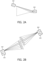
- FIG. 1A and 1B depict respectively one OWC transceiver arranged to communicate with one another using a point-to-point optical link.
- Each of the optical wireless systems may be connected to a local network (such as an in-vehicle network), or other communication port (104, 204).
- Each of the OWC transceivers further comprises a baseband unit, which is configured to modulate and demodulate incoming and outgoing data signals in a bi-directional manner between the communication port and an optical transmitter (103, 202) and optical receiver (102, 203) of the respective optical front-end unit of the OWC transceivers.
- the transmitter of a unit (103) and its opposite receiver (203) on the other unit require aligned. If a transmitter and a receiver have different fields-of-view, also referred to as opening angles, it is sufficient for a good connection that the cones or beam patterns have substantial overlap. Generally, the more overlap the better the connection.
- the transmitter beam has to overlap at least partially the receiver beam close to the receiver source, as it is shown in Figure 2A .
- each transceiver system to have multiple narrow angle transmitters, composed of a separate optical emitter, lens, and amplifier, each one of them pointing in a different direction, and a single flat wide-angle receiver. All transmitters will be connectable to the single baseband output signal, where one or more of these transmitters can be activated at a time providing an output signal through the best aligned transmitter beam (or a combination of the best aligned ones).
- Figure 2B shows this architecture used in a point-to-point system, with a different ID indicating a transmitter beam that points to a different direction.
- the transmitter unit 1 103 selects the beam ID 2 as the strongest one, while due to the orientation, the transmitter unit 2 202 selects the beam ID 3.
- Both receivers 102, 203 have a receiving optical angle equal or larger than the combined transmission angle of all transmitter-beams together.
- the solid cone of the receiver field of view is wider than the solid cone of the combined transmitter field of views.
- the minimum distance may be configured such that continuous communication is possible in realistic scenarios between like vehicles or assuming a known placement of the OWC transceivers. In practice, this could be in close proximity in a traffic jam, in the 1-to-5-meter range, or at a normal safe driving distance, which depends on the type of vehicle.
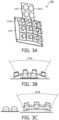
- Figure 3A shows an exemplary mechanical assembly of a perspective view of an optical front-end unit 400
- Figure 3B and 3C show a corresponding top and side view of the optical front-end unit 400 respectively.
- a common transmitter board 103 which includes a number of individual transmitters 103a..n, each of them mounted in separated boards which are mechanically assembled at an angle, to form an overall larger angle of coverage in both horizontal and vertical axis.
- the receiver board 102 is assembled flat, and it is composed of one or more wide-angle photodetectors 102a and receiver circuits, all pointing to the same direction.
- the optical front-end unit 400 includes a common transmitter board 103, which includes a number of individual transmitters 103a..n, each of them mounted on separated boards which are mechanically assembled at an angle, to form an overall larger angle of coverage in both horizontal and vertical direction.
- the driver(s) for the respective optical transmitters are not shown.
- the receiver board 102 is assembled flat, and it is composed of one or more wide-angle photodetectors 102a, all pointing in the same direction.
- the receiver board may include receiver circuits (not shown).
- the depicted optical front-end has a 4x3 configuration of optical transmitters, resulting in a slightly wide horizontal field-of-view (35 degrees) than the vertical field-of-view (25 degrees). This is practical for vehicle-to-vehicle communication in view of the nature of traffic flow and the limitations of hill-climbing/descending capabilities of commercial vehicles.
- the optical transmitters in turn may for example make use of VCSELs with appropriate optics to generate a wider field of view, or LEDs.
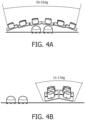
- Figure 4A and 4B in turn depict a top and side view of another exemplary mechanical assembly of a perspective view of an optical front-end unit 400.
- the optical front-end has a 6x2 configuration of optical transmitters, as a result the horizontal field of view is more pronounced, i.e. in the range of 50-55 degrees and the vertical field of view is 15-17 degrees.
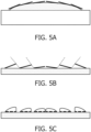
- Figure 5A shows a cross section along the horizontal axis of the top-view of Figure 5A .
- the optical transmitters are placed on a curved surface, which in this cross-section is a flat curve, but which in case of the full three-dimensional surface that is curved around a first axis and curved around a second axis, the first and second axis orthogonal to one another, the first axis perpendicular to the first direction, the second axis perpendicular to the second direction.
- the dead-zones between the emitters can be significantly reduced.
- the transmitters may alternatively by placed with at least one point on a flat surface. In this case, it may be necessary to space apart some of the emitters, so as to prevent occlusion of the emissions from one of the emitters. In this manner the individual field of view of each transmitter can be exploited. This is strictly speaking not be necessary, as in case of occlusion, that segment of the combined transmission field of view would then be covered by the neighbouring device, however occlusions may result in abrupt changes of signal quality upon movement.
- FIG. 6 A more detailed diagram of the electronic/optics of the transceiver system proposed is shown in Fig. 6 .
- the transceiver system depicted there may be used for performing beam selection, in conjunction with a similar type of transceiver system (as discussed in relation to Fig. 2B ).
- the transceiver may transmit out-of-band low-frequency CDMA beacons for use in beam selection.
- the CDMA beacons may be generated using dedicated hardware, or alternatively using a controller.
- the chip time is constant, and it is the same for all chip sequences.
- the receiver can decode simultaneously the original messages of all transmitters by cross-correlating the received signal with the same N-chip sequences used for encoding the messages. This will produce a peak in the correlation when part of the signal matches a chip sequence.
- beaconing we can use a different chip sequence to encode a single bit, producing messages of length N.
- CDMA beacons can make do with lower power than the main high-speed signal (in the order of 10-100 times less). As a result, usage of CDMA allows to have all transmitters transmit CDMA beacons continuously, while only the selected high-speed transmitter with the best orientation is connected to the output signal from the base-band unit 101.
- the out-of-band (OOB) emitted beacons preferably use the same optical transmitters and receiver as the main optical signal.
- one or more photodiodes 108 receive the signal containing both the high-speed communication signal and the out-of-band signal (CDMA beacons), which is then amplified with one or more TIA 107 and then summed if required.
- the high-speed signal follows then the path to the input of the baseband unit 101, where the main channel signal is demodulated.
- a low-pass filter 211 is placed after the first amplification, and further amplified when required with an extra low-bandwidth TIA 212. After this, this signal is fed to a controller 209, where using an ADC (which can be internal or external) the signal is converted so as to enable digital signal processing.
- ADC which can be internal or external
- the controller For each of the selectable oriented beam transmitters 103a... n, the controller generates the OOB CDMA beacon which is amplified 111 and coupled to the light source 109, possibly together with the high-speed signal. To activate the selected high-speed beam transmitter, the controller needs to connect the path from the baseband to the high-frequency amplifier 110 by means of a switch 112 as well as change the DC current of the light source 113.
- Each of the optical wireless transmitter blocks in turn generates a different OOB CDMA-based ID, each transmitter pointing to a different direction, as shown in Fig. 2B .
- the beacons which are continuously being sent by the first system 100 to the second system 200 need to be sent back to the first system 100 to inform this one of which is the better aligned transmitter at that moment (and vice versa from the second system to the first system). Therefore, the communication needs to be bi-directional but sufficiently fast, as some applications such as vehicle-to-vehicle communications need a fast response/reaction time.
- a first mechanism proposed that allows fast beam selection, may be performed by the controller and transceiver system, is the following:
- reaction time can be faster, as the system is continuously transmitting in the same state, with each transmitter sending a different beacon, and the received beacon is encoded back in the extra spacing of all beacons.
- a further improvement to the system can be to connect more than one high-speed transmitter path at the same time, which can be used for either increasing throughput by link aggregation or performing a smooth handover when switching between different beams.
- a simple alternative is one wherein the first transceiver system transmits a different predetermined output beacon, in the form of a discrete pilot tone with a different frequency f 1,1 ..f 1,n for n wireless optical transmitters facing in n orientations and wherein the frequencies f 1,1 ..f 1,n are outside the frequency band used for the main transmission.
- the second transceiver system analogous to the first method presented herein above, detect the presence of the respective sinewave through simply bandpass filtering and pilot tone detection (e.g. using a Fourier analysis).
- pilot tone detection e.g. using a Fourier analysis
- the second transceiver system may temporarily emit a different sine wave selected from the set of further different frequencies f 2,1 ..f 2,n wherein f 2,x is used to reflect that signal f 1,x was received.
- the second transceiver system may itself continue to emit the discrete pilot tones with a frequency f 1,1 ..f 1,n for each of its respective ones of the n wireless optical transmitters facing in n orientations.
- both the first and the second transceiver system may thereby each inform the other system which of their transmitters is best suited and receive feedback from the other system allowing selection of their own transmitter.
- each of the transceiver systems includes in its respective beacons information uniquely identifying the transmitter, information perceptible to a like transceiver system, which allows the like transceiver system to detect the uniquely identifying information and to temporarily switch from beaconing its own uniquely identifying transmitter information to conveying feedback by beaconing the received uniquely identifying transmitter information in a for the transceiver system discernible form, thereby allowing the transceiver system to select an appropriate transceiver system.
- codes, frequencies or other uniquely identifying transmitter information should be available at both communication partners and may for example use a predefined convention, may be standardized or set during a commissioning period allowing the communication partners to perform the beam selection task.
- controller is used herein generally to describe various apparatus relating to, among other functions, the operation of one or more network devices or coordinators.
- a controller can be implemented in numerous ways (e.g., such as with dedicated hardware) to perform various functions discussed herein.
- a "processor” is one example of a controller which employs one or more microprocessors that may be programmed using software (e.g., microcode) to perform various functions discussed herein.
- a controller may be implemented with or without employing a processor, and also may be implemented as a combination of dedicated hardware to perform some functions and a processor (e.g., one or more programmed microprocessors and associated circuitry) to perform other functions. Examples of controller components that may be employed in various embodiments of the present disclosure include, but are not limited to, conventional microprocessors, application specific integrated circuits (ASICs), and field-programmable gate arrays (FPGAs).
- ASICs application specific integrated circuits
- FPGAs field-programmable gate arrays
- a processor or controller may be associated with one or more storage media (generically referred to herein as "memory,” e.g., volatile and non-volatile computer memory such as RAM, PROM, EPROM, and EEPROM, compact disks, optical disks, etc.).
- the storage media may be encoded with one or more programs that, when executed on one or more processors and/or controllers, perform at least some of the functions discussed herein.
- Various storage media may be fixed within a processor or controller or may be transportable, such that the one or more programs stored thereon can be loaded into a processor or controller so as to implement various aspects of the present invention discussed herein.
- program or “computer program” are used herein in a generic sense to refer to any type of computer code (e.g., software or microcode) that can be employed to program one or more processors or controllers.
- network refers to any interconnection of two or more devices (including controllers or processors) that facilitates the transport of information (e.g. for device control, data storage, data exchange, etc.) between any two or more devices and/or among multiple devices coupled to the network.
- devices including controllers or processors
- information e.g. for device control, data storage, data exchange, etc.
Landscapes
- Engineering & Computer Science (AREA)
- Physics & Mathematics (AREA)
- Electromagnetism (AREA)
- Computer Networks & Wireless Communication (AREA)
- Signal Processing (AREA)
- Computing Systems (AREA)
- Optical Communication System (AREA)
Claims (9)
- Optisches Front-End, OFE, für eine optische drahtlose Kommunikation, OWC, das OFE umfassend:- einen optischen Empfänger (102) mit mindestens einem Photodetektor, wobei der mindestens eine Photodetektor in eine Detektionsrichtung weist, und einen Transimpedanzverstärker, TIA, zum Verstärken des Signals von dem mindestens einen Photodetektor, und- eine zweidimensionale Anordnung von optischen Sendern (103a), von denen jeder ein individuelles Sendersichtfeld, und entsprechende Treiber aufweist,wobei die zweidimensionale Anordnung angeordnet ist, um ein kombiniertes Sendersichtfeld zu erzeugen, das größer als das individuelle Sendersichtfeld ist, und wobei die Anzahl der optischen Sender entlang einer ersten Richtung größer als die Anzahl der optischen Sender entlang einer zweiten Richtung ist, und das kombinierte Sendersichtfeld in der ersten Richtung größer als in der zweiten Richtung ist, wobei die erste Richtung orthogonal zu der zweiten Richtung ist und die optischen Sender derart angeordnet sind, dass die optischen Achsen der optischen Sender gleichmäßig innerhalb des kombinierten Sendersichtfelds verteilt sind,wobei der optische Empfänger auf einem flachen Substrat montiert ist, wobei seine optische Achse mit der optischen Achse des kombinierten Sendersichtfelds ausgerichtet ist, und das Empfängersichtfeld größer als oder gleich dem kombinierten Sendersichtfeld ist, undwobei die optischen Sender Folgendes sind, entweder:- entlang einer Oberfläche positioniert, die um eine erste Achse gekrümmt ist und um eine zweite Achse gekrümmt ist, wobei die erste und die zweite Achse orthogonal zueinander sind, die erste Achse senkrecht zu der ersten Richtung ist, die zweite Achse senkrecht zu der zweiten Richtung ist;- mit mindestens einem Punkt auf einer flachen Oberfläche positioniert, wobei jeder optische Sender angewinkelt ist, um in eine unterschiedliche Richtung zu weisen, oder- auf einer flachen Oberfläche positioniert und mit einem entsprechenden Lichtwellenleiter zum gerichteten Auskoppeln ausgestattet.
- OFE nach Anspruch 1, wobei die Anordnung von optischen Sendern in einer Matrix entlang zweier orthogonaler Richtungen oder in einer hexagonalen Struktur angeordnet ist.
- OFE nach Anspruch 1 oder 2, wobei das kombinierte Sendersichtfeld in der ersten Richtung innerhalb eines Bereichs von 30 Grad bis 90 Grad und in der zweiten Richtung innerhalb eines Bereichs von 10 Grad bis 60 Grad liegt.
- OWC-Transceiversystem für eine optische drahtlose Kommunikation, OWC, zur Verwendung mit einem weiteren OWC-Transceiversystem, das OWC-Transceiversystem umfassend:- ein optisches Front-End, OFE, nach Anspruch 1, wobei das OFE einen separaten Treiber für jeden der Vielzahl von optischen Sendern einschließt,- eine Basisbandeinheit, die konfiguriert ist, um ausgehende Daten für die Übertragung durch das OFE zu modulieren und eingehende Daten für den Ausgang des Transimpedanzverstärkers des OFE zu demodulieren,- eine Steuerung, die konfiguriert ist, um zu steuern, welche der Vielzahl von optischen Sendern zum Übertragen der ausgehenden Daten, basierend auf dem Ergebnis eines Ausrichtungsvorgangs, verwendet werden.
- OWC-Transceiver nach Anspruch 4, wobei die Steuerung angeordnet ist, um einen Ausrichtungsvorgang mit dem weiteren OWC-Transceiversystem durchzuführen, wobei die Steuerung konfiguriert ist zum:- Generieren eindeutiger Ausrichtungsbaken, umfassend Identifizierungsinformationen für jeden einzelnen der Vielzahl von optischen Sendern;- Steuern jeden der Vielzahl von Sendern, um seine jeweilige Ausrichtungsbake zu senden;- Empfangen, in der Ausgabe des TIA, einer Rückmeldung, die durch den Kommunikationspartner gesendet wird, über eine Detektion von einem Kommunikationspartner, über ein eindeutiges Attribut eines optischen Senders des OWC-Transceiversystems in einer Bake von dem OWC-Transceiversystem; und- Auswählen einer geeigneten Teilmenge aus der Vielzahl von optischen Sendern zum Senden der ausgehenden Daten an das weitere OWC-Transceiversystem basierend auf der Rückmeldung.
- OWC-Transceiver nach Anspruch 5, wobei- die Ausrichtungsbaken niederfrequente CDMA-Baken sind, die außerhalb des Bandes der Ausgabedaten gesendet werden, wodurch ermöglicht wird, dass optische Sender Ausrichtungsbaken und Ausgabedaten gleichzeitig senden; und- wobei die Rückmeldung über die Detektion von dem Kommunikationspartner eine Bake ist, die durch den Kommunikationspartner gesendet wird, mit einer invertierten Version der CDMA-Sequenz, wie sie durch einen jeweiligen der von dem Kommunikationspartner empfangenen optischen Sender gesendet wurde.
- Fahrzeug, das für die optische Kommunikation angeordnet ist, das Fahrzeug umfassend:- ein fahrzeuginternes Netzwerk,- einen ersten OWC-Transceiver, umfassend ein nach vorne gerichtetes OFE nach Anspruch 1, wobei die optische Achse des nach vorne gerichteten OFE in die nach vorne gerichtete Bewegungsrichtung des Fahrzeugs weist, wobei das fahrzeuginterne Netzwerk mit dem ersten OWC-Transceiver verbunden ist.
- Fahrzeug nach Anspruch 7, das Fahrzeug ferner umfassend:- einen zweiten OWC-Transceiver, umfassend ein nach hinten gerichtetes OFE nach Anspruch 1, wobei die optische Achse des nach hinten gerichteten OFE in die entgegengesetzte Richtung der nach vorne gerichteten Bewegungsrichtung des Fahrzeugs weist, wobei das fahrzeuginterne Netzwerk mit dem zweiten OWC-Transceiver verbunden ist.
- Fahrzeug nach Anspruch 7 oder 8, wobei das Fahrzeug ein Auto, ein Bus, ein Zug, ein Boot oder ein LKW ist.
Applications Claiming Priority (3)
| Application Number | Priority Date | Filing Date | Title |
|---|---|---|---|
| EP21171082 | 2021-04-29 | ||
| EP21212679 | 2021-12-07 | ||
| PCT/EP2022/060746 WO2022229029A1 (en) | 2021-04-29 | 2022-04-22 | Optical frontend for use in optical wireless communication |
Publications (2)
| Publication Number | Publication Date |
|---|---|
| EP4331141A1 EP4331141A1 (de) | 2024-03-06 |
| EP4331141B1 true EP4331141B1 (de) | 2024-11-20 |
Family
ID=81750580
Family Applications (1)
| Application Number | Title | Priority Date | Filing Date |
|---|---|---|---|
| EP22724747.5A Active EP4331141B1 (de) | 2021-04-29 | 2022-04-22 | Optisches frontend zur verwendung in der optischen drahtlosen kommunikation |
Country Status (3)
| Country | Link |
|---|---|
| US (1) | US20240223278A1 (de) |
| EP (1) | EP4331141B1 (de) |
| WO (1) | WO2022229029A1 (de) |
Families Citing this family (1)
| Publication number | Priority date | Publication date | Assignee | Title |
|---|---|---|---|---|
| CN121890013A (zh) * | 2023-09-05 | 2026-04-17 | 昕诺飞控股有限公司 | 触发光学无线通信终端设备的配置模式的方法 |
Family Cites Families (3)
| Publication number | Priority date | Publication date | Assignee | Title |
|---|---|---|---|---|
| US8301027B2 (en) * | 2008-05-02 | 2012-10-30 | Massachusetts Institute Of Technology | Agile-beam laser array transmitter |
| WO2017139317A1 (en) * | 2016-02-09 | 2017-08-17 | Lumeova, Inc | Ultra-wideband, wireless optical high speed communication devices and systems |
| GB201907574D0 (en) * | 2019-05-29 | 2019-07-10 | Purelifi Ltd | Light communication system and method |
-
2022
- 2022-04-22 EP EP22724747.5A patent/EP4331141B1/de active Active
- 2022-04-22 US US18/557,326 patent/US20240223278A1/en active Pending
- 2022-04-22 WO PCT/EP2022/060746 patent/WO2022229029A1/en not_active Ceased
Also Published As
| Publication number | Publication date |
|---|---|
| WO2022229029A1 (en) | 2022-11-03 |
| EP4331141A1 (de) | 2024-03-06 |
| US20240223278A1 (en) | 2024-07-04 |
Similar Documents
| Publication | Publication Date | Title |
|---|---|---|
| US10281581B2 (en) | Lidar with optical communication | |
| US8103167B2 (en) | System for free space optical communication and method for operation thereof | |
| JP3756152B2 (ja) | 速いマルチビーム自由空間光通信装置 | |
| EP0338789A2 (de) | Infrarote Datenübertragung | |
| EP3257171A1 (de) | Kommunikation zwischen fahrzeugen eines zuges | |
| EP4331141B1 (de) | Optisches frontend zur verwendung in der optischen drahtlosen kommunikation | |
| JP7191399B2 (ja) | 環境の空間プロファイルの推定 | |
| KR100876725B1 (ko) | 가시광 통신을 이용한 무선 랜 시스템에서 통신 링크 연결방법 | |
| EP0856970B1 (de) | Übertragungskollisionsdetektion | |
| EP3698487A1 (de) | Optische drahtlose kommunikation | |
| CN113162688B (zh) | 一种可见光双向通信与定位系统 | |
| EP4331140B1 (de) | Sender-empfängersystem für optische drahtlose kommunikation | |
| EP4091267B1 (de) | Lifi-leistungsverwaltung | |
| CN117223233A (zh) | 用在光学无线通信中的光学前端 | |
| CN113728562B (zh) | 第一模块与第二模块之间的数据传输方法以及实施该方法的具有移动装置的设施 | |
| KR101413487B1 (ko) | 스폿 led 조명 빔포밍 시스템 및 방법 | |
| EP4331142B1 (de) | Verfahren zur strahlausrichtung in optischen drahtlosen punkt-zu-punkt-kommunikationssystemen | |
| EP2899903A1 (de) | Vorrichtung zur kommunikation mit sichtbarem licht | |
| EP4505632B1 (de) | Sichere optische drahtlose kommunikationsverbindung | |
| JP2002353900A (ja) | 光無線伝送システムおよび光無線伝送方法 | |
| WO2026013150A1 (en) | Optical wireless communication system, method for optical wireless communication, transmitter device and receiver device | |
| CN113328800A (zh) | 一种空间光通信全向接收方法和设备 | |
| JP3776836B2 (ja) | 赤外線通信装置 | |
| WO2001095282A2 (en) | Alignment of narrow beam transmission | |
| Student | VEHICLE TO VEHICLE COMMUNICATION USING “VISIBLE LIGHT COMMUNICATION TECHNOLOGY” |
Legal Events
| Date | Code | Title | Description |
|---|---|---|---|
| STAA | Information on the status of an ep patent application or granted ep patent |
Free format text: STATUS: UNKNOWN |
|
| STAA | Information on the status of an ep patent application or granted ep patent |
Free format text: STATUS: THE INTERNATIONAL PUBLICATION HAS BEEN MADE |
|
| PUAI | Public reference made under article 153(3) epc to a published international application that has entered the european phase |
Free format text: ORIGINAL CODE: 0009012 |
|
| STAA | Information on the status of an ep patent application or granted ep patent |
Free format text: STATUS: REQUEST FOR EXAMINATION WAS MADE |
|
| 17P | Request for examination filed |
Effective date: 20231129 |
|
| AK | Designated contracting states |
Kind code of ref document: A1 Designated state(s): AL AT BE BG CH CY CZ DE DK EE ES FI FR GB GR HR HU IE IS IT LI LT LU LV MC MK MT NL NO PL PT RO RS SE SI SK SM TR |
|
| GRAP | Despatch of communication of intention to grant a patent |
Free format text: ORIGINAL CODE: EPIDOSNIGR1 |
|
| STAA | Information on the status of an ep patent application or granted ep patent |
Free format text: STATUS: GRANT OF PATENT IS INTENDED |
|
| DAV | Request for validation of the european patent (deleted) | ||
| DAX | Request for extension of the european patent (deleted) | ||
| INTG | Intention to grant announced |
Effective date: 20240613 |
|
| P01 | Opt-out of the competence of the unified patent court (upc) registered |
Free format text: CASE NUMBER: APP_44556/2024 Effective date: 20240731 |
|
| GRAS | Grant fee paid |
Free format text: ORIGINAL CODE: EPIDOSNIGR3 |
|
| GRAA | (expected) grant |
Free format text: ORIGINAL CODE: 0009210 |
|
| STAA | Information on the status of an ep patent application or granted ep patent |
Free format text: STATUS: THE PATENT HAS BEEN GRANTED |
|
| AK | Designated contracting states |
Kind code of ref document: B1 Designated state(s): AL AT BE BG CH CY CZ DE DK EE ES FI FR GB GR HR HU IE IS IT LI LT LU LV MC MK MT NL NO PL PT RO RS SE SI SK SM TR |
|
| REG | Reference to a national code |
Ref country code: GB Ref legal event code: FG4D |
|
| REG | Reference to a national code |
Ref country code: CH Ref legal event code: EP |
|
| REG | Reference to a national code |
Ref country code: DE Ref legal event code: R096 Ref document number: 602022007980 Country of ref document: DE |
|
| REG | Reference to a national code |
Ref country code: IE Ref legal event code: FG4D |
|
| REG | Reference to a national code |
Ref country code: LT Ref legal event code: MG9D |
|
| REG | Reference to a national code |
Ref country code: NL Ref legal event code: MP Effective date: 20241120 |
|
| PG25 | Lapsed in a contracting state [announced via postgrant information from national office to epo] |
Ref country code: IS Free format text: LAPSE BECAUSE OF FAILURE TO SUBMIT A TRANSLATION OF THE DESCRIPTION OR TO PAY THE FEE WITHIN THE PRESCRIBED TIME-LIMIT Effective date: 20250320 Ref country code: PT Free format text: LAPSE BECAUSE OF FAILURE TO SUBMIT A TRANSLATION OF THE DESCRIPTION OR TO PAY THE FEE WITHIN THE PRESCRIBED TIME-LIMIT Effective date: 20250320 Ref country code: HR Free format text: LAPSE BECAUSE OF FAILURE TO SUBMIT A TRANSLATION OF THE DESCRIPTION OR TO PAY THE FEE WITHIN THE PRESCRIBED TIME-LIMIT Effective date: 20241120 |
|
| PG25 | Lapsed in a contracting state [announced via postgrant information from national office to epo] |
Ref country code: FI Free format text: LAPSE BECAUSE OF FAILURE TO SUBMIT A TRANSLATION OF THE DESCRIPTION OR TO PAY THE FEE WITHIN THE PRESCRIBED TIME-LIMIT Effective date: 20241120 Ref country code: NL Free format text: LAPSE BECAUSE OF FAILURE TO SUBMIT A TRANSLATION OF THE DESCRIPTION OR TO PAY THE FEE WITHIN THE PRESCRIBED TIME-LIMIT Effective date: 20241120 |
|
| REG | Reference to a national code |
Ref country code: AT Ref legal event code: MK05 Ref document number: 1744504 Country of ref document: AT Kind code of ref document: T Effective date: 20241120 |
|
| PG25 | Lapsed in a contracting state [announced via postgrant information from national office to epo] |
Ref country code: BG Free format text: LAPSE BECAUSE OF FAILURE TO SUBMIT A TRANSLATION OF THE DESCRIPTION OR TO PAY THE FEE WITHIN THE PRESCRIBED TIME-LIMIT Effective date: 20241120 |
|
| PG25 | Lapsed in a contracting state [announced via postgrant information from national office to epo] |
Ref country code: ES Free format text: LAPSE BECAUSE OF FAILURE TO SUBMIT A TRANSLATION OF THE DESCRIPTION OR TO PAY THE FEE WITHIN THE PRESCRIBED TIME-LIMIT Effective date: 20241120 |
|
| PG25 | Lapsed in a contracting state [announced via postgrant information from national office to epo] |
Ref country code: NO Free format text: LAPSE BECAUSE OF FAILURE TO SUBMIT A TRANSLATION OF THE DESCRIPTION OR TO PAY THE FEE WITHIN THE PRESCRIBED TIME-LIMIT Effective date: 20250220 |
|
| PG25 | Lapsed in a contracting state [announced via postgrant information from national office to epo] |
Ref country code: GR Free format text: LAPSE BECAUSE OF FAILURE TO SUBMIT A TRANSLATION OF THE DESCRIPTION OR TO PAY THE FEE WITHIN THE PRESCRIBED TIME-LIMIT Effective date: 20250221 Ref country code: LV Free format text: LAPSE BECAUSE OF FAILURE TO SUBMIT A TRANSLATION OF THE DESCRIPTION OR TO PAY THE FEE WITHIN THE PRESCRIBED TIME-LIMIT Effective date: 20241120 Ref country code: AT Free format text: LAPSE BECAUSE OF FAILURE TO SUBMIT A TRANSLATION OF THE DESCRIPTION OR TO PAY THE FEE WITHIN THE PRESCRIBED TIME-LIMIT Effective date: 20241120 |
|
| PG25 | Lapsed in a contracting state [announced via postgrant information from national office to epo] |
Ref country code: PL Free format text: LAPSE BECAUSE OF FAILURE TO SUBMIT A TRANSLATION OF THE DESCRIPTION OR TO PAY THE FEE WITHIN THE PRESCRIBED TIME-LIMIT Effective date: 20241120 |
|
| PG25 | Lapsed in a contracting state [announced via postgrant information from national office to epo] |
Ref country code: RS Free format text: LAPSE BECAUSE OF FAILURE TO SUBMIT A TRANSLATION OF THE DESCRIPTION OR TO PAY THE FEE WITHIN THE PRESCRIBED TIME-LIMIT Effective date: 20250220 |
|
| PG25 | Lapsed in a contracting state [announced via postgrant information from national office to epo] |
Ref country code: SM Free format text: LAPSE BECAUSE OF FAILURE TO SUBMIT A TRANSLATION OF THE DESCRIPTION OR TO PAY THE FEE WITHIN THE PRESCRIBED TIME-LIMIT Effective date: 20241120 |
|
| PGFP | Annual fee paid to national office [announced via postgrant information from national office to epo] |
Ref country code: DE Payment date: 20250626 Year of fee payment: 4 |
|
| PG25 | Lapsed in a contracting state [announced via postgrant information from national office to epo] |
Ref country code: DK Free format text: LAPSE BECAUSE OF FAILURE TO SUBMIT A TRANSLATION OF THE DESCRIPTION OR TO PAY THE FEE WITHIN THE PRESCRIBED TIME-LIMIT Effective date: 20241120 |
|
| PG25 | Lapsed in a contracting state [announced via postgrant information from national office to epo] |
Ref country code: EE Free format text: LAPSE BECAUSE OF FAILURE TO SUBMIT A TRANSLATION OF THE DESCRIPTION OR TO PAY THE FEE WITHIN THE PRESCRIBED TIME-LIMIT Effective date: 20241120 |
|
| PGFP | Annual fee paid to national office [announced via postgrant information from national office to epo] |
Ref country code: FR Payment date: 20250424 Year of fee payment: 4 |
|
| PG25 | Lapsed in a contracting state [announced via postgrant information from national office to epo] |
Ref country code: RO Free format text: LAPSE BECAUSE OF FAILURE TO SUBMIT A TRANSLATION OF THE DESCRIPTION OR TO PAY THE FEE WITHIN THE PRESCRIBED TIME-LIMIT Effective date: 20241120 |
|
| PG25 | Lapsed in a contracting state [announced via postgrant information from national office to epo] |
Ref country code: SK Free format text: LAPSE BECAUSE OF FAILURE TO SUBMIT A TRANSLATION OF THE DESCRIPTION OR TO PAY THE FEE WITHIN THE PRESCRIBED TIME-LIMIT Effective date: 20241120 |
|
| PG25 | Lapsed in a contracting state [announced via postgrant information from national office to epo] |
Ref country code: CZ Free format text: LAPSE BECAUSE OF FAILURE TO SUBMIT A TRANSLATION OF THE DESCRIPTION OR TO PAY THE FEE WITHIN THE PRESCRIBED TIME-LIMIT Effective date: 20241120 |
|
| PG25 | Lapsed in a contracting state [announced via postgrant information from national office to epo] |
Ref country code: IT Free format text: LAPSE BECAUSE OF FAILURE TO SUBMIT A TRANSLATION OF THE DESCRIPTION OR TO PAY THE FEE WITHIN THE PRESCRIBED TIME-LIMIT Effective date: 20241120 |
|
| REG | Reference to a national code |
Ref country code: DE Ref legal event code: R097 Ref document number: 602022007980 Country of ref document: DE |
|
| PG25 | Lapsed in a contracting state [announced via postgrant information from national office to epo] |
Ref country code: SE Free format text: LAPSE BECAUSE OF FAILURE TO SUBMIT A TRANSLATION OF THE DESCRIPTION OR TO PAY THE FEE WITHIN THE PRESCRIBED TIME-LIMIT Effective date: 20241120 |
|
| PLBE | No opposition filed within time limit |
Free format text: ORIGINAL CODE: 0009261 |
|
| STAA | Information on the status of an ep patent application or granted ep patent |
Free format text: STATUS: NO OPPOSITION FILED WITHIN TIME LIMIT |
|
| 26N | No opposition filed |
Effective date: 20250821 |
|
| REG | Reference to a national code |
Ref country code: CH Ref legal event code: H13 Free format text: ST27 STATUS EVENT CODE: U-0-0-H10-H13 (AS PROVIDED BY THE NATIONAL OFFICE) Effective date: 20251125 |
|
| PG25 | Lapsed in a contracting state [announced via postgrant information from national office to epo] |
Ref country code: LU Free format text: LAPSE BECAUSE OF NON-PAYMENT OF DUE FEES Effective date: 20250422 |
|
| PG25 | Lapsed in a contracting state [announced via postgrant information from national office to epo] |
Ref country code: MC Free format text: LAPSE BECAUSE OF FAILURE TO SUBMIT A TRANSLATION OF THE DESCRIPTION OR TO PAY THE FEE WITHIN THE PRESCRIBED TIME-LIMIT Effective date: 20241120 |
|
| REG | Reference to a national code |
Ref country code: BE Ref legal event code: MM Effective date: 20250430 |
|
| PG25 | Lapsed in a contracting state [announced via postgrant information from national office to epo] |
Ref country code: BE Free format text: LAPSE BECAUSE OF NON-PAYMENT OF DUE FEES Effective date: 20250430 |
|
| PG25 | Lapsed in a contracting state [announced via postgrant information from national office to epo] |
Ref country code: CH Free format text: LAPSE BECAUSE OF NON-PAYMENT OF DUE FEES Effective date: 20250430 |
|
| PGFP | Annual fee paid to national office [announced via postgrant information from national office to epo] |
Ref country code: GB Payment date: 20260226 Year of fee payment: 5 |
|
| PG25 | Lapsed in a contracting state [announced via postgrant information from national office to epo] |
Ref country code: IE Free format text: LAPSE BECAUSE OF NON-PAYMENT OF DUE FEES Effective date: 20250422 |