EP4329683B1 - Trial component and method - Google Patents
Trial component and method Download PDFInfo
- Publication number
- EP4329683B1 EP4329683B1 EP22726618.6A EP22726618A EP4329683B1 EP 4329683 B1 EP4329683 B1 EP 4329683B1 EP 22726618 A EP22726618 A EP 22726618A EP 4329683 B1 EP4329683 B1 EP 4329683B1
- Authority
- EP
- European Patent Office
- Prior art keywords
- bore
- arms
- pair
- neck
- proximal end
- Prior art date
- Legal status (The legal status is an assumption and is not a legal conclusion. Google has not performed a legal analysis and makes no representation as to the accuracy of the status listed.)
- Active
Links
Images





Classifications
-
- A—HUMAN NECESSITIES
- A61—MEDICAL OR VETERINARY SCIENCE; HYGIENE
- A61F—FILTERS IMPLANTABLE INTO BLOOD VESSELS; PROSTHESES; DEVICES PROVIDING PATENCY TO, OR PREVENTING COLLAPSING OF, TUBULAR STRUCTURES OF THE BODY, e.g. STENTS; ORTHOPAEDIC, NURSING OR CONTRACEPTIVE DEVICES; FOMENTATION; TREATMENT OR PROTECTION OF EYES OR EARS; BANDAGES, DRESSINGS OR ABSORBENT PADS; FIRST-AID KITS
- A61F2/00—Filters implantable into blood vessels; Prostheses, i.e. artificial substitutes or replacements for parts of the body; Appliances for connecting them with the body; Devices providing patency to, or preventing collapsing of, tubular structures of the body, e.g. stents
- A61F2/02—Prostheses implantable into the body
- A61F2/30—Joints
- A61F2/46—Special tools for implanting artificial joints
- A61F2/4684—Trial or dummy prostheses
-
- A—HUMAN NECESSITIES
- A61—MEDICAL OR VETERINARY SCIENCE; HYGIENE
- A61F—FILTERS IMPLANTABLE INTO BLOOD VESSELS; PROSTHESES; DEVICES PROVIDING PATENCY TO, OR PREVENTING COLLAPSING OF, TUBULAR STRUCTURES OF THE BODY, e.g. STENTS; ORTHOPAEDIC, NURSING OR CONTRACEPTIVE DEVICES; FOMENTATION; TREATMENT OR PROTECTION OF EYES OR EARS; BANDAGES, DRESSINGS OR ABSORBENT PADS; FIRST-AID KITS
- A61F2/00—Filters implantable into blood vessels; Prostheses, i.e. artificial substitutes or replacements for parts of the body; Appliances for connecting them with the body; Devices providing patency to, or preventing collapsing of, tubular structures of the body, e.g. stents
- A61F2/02—Prostheses implantable into the body
- A61F2/30—Joints
- A61F2/32—Joints for the hip
- A61F2/36—Femoral heads ; Femoral endoprostheses
- A61F2/3609—Femoral heads or necks; Connections of endoprosthetic heads or necks to endoprosthetic femoral shafts
-
- A—HUMAN NECESSITIES
- A61—MEDICAL OR VETERINARY SCIENCE; HYGIENE
- A61F—FILTERS IMPLANTABLE INTO BLOOD VESSELS; PROSTHESES; DEVICES PROVIDING PATENCY TO, OR PREVENTING COLLAPSING OF, TUBULAR STRUCTURES OF THE BODY, e.g. STENTS; ORTHOPAEDIC, NURSING OR CONTRACEPTIVE DEVICES; FOMENTATION; TREATMENT OR PROTECTION OF EYES OR EARS; BANDAGES, DRESSINGS OR ABSORBENT PADS; FIRST-AID KITS
- A61F2/00—Filters implantable into blood vessels; Prostheses, i.e. artificial substitutes or replacements for parts of the body; Appliances for connecting them with the body; Devices providing patency to, or preventing collapsing of, tubular structures of the body, e.g. stents
- A61F2/02—Prostheses implantable into the body
- A61F2/30—Joints
- A61F2/32—Joints for the hip
- A61F2/36—Femoral heads ; Femoral endoprostheses
- A61F2/3662—Femoral shafts
-
- A—HUMAN NECESSITIES
- A61—MEDICAL OR VETERINARY SCIENCE; HYGIENE
- A61B—DIAGNOSIS; SURGERY; IDENTIFICATION
- A61B17/00—Surgical instruments, devices or methods
- A61B17/16—Instruments for performing osteoclasis; Drills or chisels for bones; Trepans
- A61B17/1662—Instruments for performing osteoclasis; Drills or chisels for bones; Trepans for particular parts of the body
- A61B17/1664—Instruments for performing osteoclasis; Drills or chisels for bones; Trepans for particular parts of the body for the hip
- A61B17/1668—Instruments for performing osteoclasis; Drills or chisels for bones; Trepans for particular parts of the body for the hip for the upper femur
-
- A—HUMAN NECESSITIES
- A61—MEDICAL OR VETERINARY SCIENCE; HYGIENE
- A61F—FILTERS IMPLANTABLE INTO BLOOD VESSELS; PROSTHESES; DEVICES PROVIDING PATENCY TO, OR PREVENTING COLLAPSING OF, TUBULAR STRUCTURES OF THE BODY, e.g. STENTS; ORTHOPAEDIC, NURSING OR CONTRACEPTIVE DEVICES; FOMENTATION; TREATMENT OR PROTECTION OF EYES OR EARS; BANDAGES, DRESSINGS OR ABSORBENT PADS; FIRST-AID KITS
- A61F2/00—Filters implantable into blood vessels; Prostheses, i.e. artificial substitutes or replacements for parts of the body; Appliances for connecting them with the body; Devices providing patency to, or preventing collapsing of, tubular structures of the body, e.g. stents
- A61F2/02—Prostheses implantable into the body
- A61F2/30—Joints
- A61F2002/30001—Additional features of subject-matter classified in A61F2/28, A61F2/30 and subgroups thereof
- A61F2002/30316—The prosthesis having different structural features at different locations within the same prosthesis; Connections between prosthetic parts; Special structural features of bone or joint prostheses not otherwise provided for
- A61F2002/30329—Connections or couplings between prosthetic parts, e.g. between modular parts; Connecting elements
- A61F2002/30331—Connections or couplings between prosthetic parts, e.g. between modular parts; Connecting elements made by longitudinally pushing a protrusion into a complementarily-shaped recess, e.g. held by friction fit
-
- A—HUMAN NECESSITIES
- A61—MEDICAL OR VETERINARY SCIENCE; HYGIENE
- A61F—FILTERS IMPLANTABLE INTO BLOOD VESSELS; PROSTHESES; DEVICES PROVIDING PATENCY TO, OR PREVENTING COLLAPSING OF, TUBULAR STRUCTURES OF THE BODY, e.g. STENTS; ORTHOPAEDIC, NURSING OR CONTRACEPTIVE DEVICES; FOMENTATION; TREATMENT OR PROTECTION OF EYES OR EARS; BANDAGES, DRESSINGS OR ABSORBENT PADS; FIRST-AID KITS
- A61F2/00—Filters implantable into blood vessels; Prostheses, i.e. artificial substitutes or replacements for parts of the body; Appliances for connecting them with the body; Devices providing patency to, or preventing collapsing of, tubular structures of the body, e.g. stents
- A61F2/02—Prostheses implantable into the body
- A61F2/30—Joints
- A61F2002/30001—Additional features of subject-matter classified in A61F2/28, A61F2/30 and subgroups thereof
- A61F2002/30316—The prosthesis having different structural features at different locations within the same prosthesis; Connections between prosthetic parts; Special structural features of bone or joint prostheses not otherwise provided for
- A61F2002/30329—Connections or couplings between prosthetic parts, e.g. between modular parts; Connecting elements
- A61F2002/30331—Connections or couplings between prosthetic parts, e.g. between modular parts; Connecting elements made by longitudinally pushing a protrusion into a complementarily-shaped recess, e.g. held by friction fit
- A61F2002/30354—Cylindrically-shaped protrusion and recess, e.g. cylinder of circular basis
-
- A—HUMAN NECESSITIES
- A61—MEDICAL OR VETERINARY SCIENCE; HYGIENE
- A61F—FILTERS IMPLANTABLE INTO BLOOD VESSELS; PROSTHESES; DEVICES PROVIDING PATENCY TO, OR PREVENTING COLLAPSING OF, TUBULAR STRUCTURES OF THE BODY, e.g. STENTS; ORTHOPAEDIC, NURSING OR CONTRACEPTIVE DEVICES; FOMENTATION; TREATMENT OR PROTECTION OF EYES OR EARS; BANDAGES, DRESSINGS OR ABSORBENT PADS; FIRST-AID KITS
- A61F2/00—Filters implantable into blood vessels; Prostheses, i.e. artificial substitutes or replacements for parts of the body; Appliances for connecting them with the body; Devices providing patency to, or preventing collapsing of, tubular structures of the body, e.g. stents
- A61F2/02—Prostheses implantable into the body
- A61F2/30—Joints
- A61F2002/30001—Additional features of subject-matter classified in A61F2/28, A61F2/30 and subgroups thereof
- A61F2002/30316—The prosthesis having different structural features at different locations within the same prosthesis; Connections between prosthetic parts; Special structural features of bone or joint prostheses not otherwise provided for
- A61F2002/30329—Connections or couplings between prosthetic parts, e.g. between modular parts; Connecting elements
- A61F2002/30476—Connections or couplings between prosthetic parts, e.g. between modular parts; Connecting elements locked by an additional locking mechanism
- A61F2002/30505—Connections or couplings between prosthetic parts, e.g. between modular parts; Connecting elements locked by an additional locking mechanism spring biased
-
- A—HUMAN NECESSITIES
- A61—MEDICAL OR VETERINARY SCIENCE; HYGIENE
- A61F—FILTERS IMPLANTABLE INTO BLOOD VESSELS; PROSTHESES; DEVICES PROVIDING PATENCY TO, OR PREVENTING COLLAPSING OF, TUBULAR STRUCTURES OF THE BODY, e.g. STENTS; ORTHOPAEDIC, NURSING OR CONTRACEPTIVE DEVICES; FOMENTATION; TREATMENT OR PROTECTION OF EYES OR EARS; BANDAGES, DRESSINGS OR ABSORBENT PADS; FIRST-AID KITS
- A61F2/00—Filters implantable into blood vessels; Prostheses, i.e. artificial substitutes or replacements for parts of the body; Appliances for connecting them with the body; Devices providing patency to, or preventing collapsing of, tubular structures of the body, e.g. stents
- A61F2/02—Prostheses implantable into the body
- A61F2/30—Joints
- A61F2002/30001—Additional features of subject-matter classified in A61F2/28, A61F2/30 and subgroups thereof
- A61F2002/30316—The prosthesis having different structural features at different locations within the same prosthesis; Connections between prosthetic parts; Special structural features of bone or joint prostheses not otherwise provided for
- A61F2002/30535—Special structural features of bone or joint prostheses not otherwise provided for
- A61F2002/30537—Special structural features of bone or joint prostheses not otherwise provided for adjustable
-
- A—HUMAN NECESSITIES
- A61—MEDICAL OR VETERINARY SCIENCE; HYGIENE
- A61F—FILTERS IMPLANTABLE INTO BLOOD VESSELS; PROSTHESES; DEVICES PROVIDING PATENCY TO, OR PREVENTING COLLAPSING OF, TUBULAR STRUCTURES OF THE BODY, e.g. STENTS; ORTHOPAEDIC, NURSING OR CONTRACEPTIVE DEVICES; FOMENTATION; TREATMENT OR PROTECTION OF EYES OR EARS; BANDAGES, DRESSINGS OR ABSORBENT PADS; FIRST-AID KITS
- A61F2/00—Filters implantable into blood vessels; Prostheses, i.e. artificial substitutes or replacements for parts of the body; Appliances for connecting them with the body; Devices providing patency to, or preventing collapsing of, tubular structures of the body, e.g. stents
- A61F2/02—Prostheses implantable into the body
- A61F2/30—Joints
- A61F2002/30001—Additional features of subject-matter classified in A61F2/28, A61F2/30 and subgroups thereof
- A61F2002/30316—The prosthesis having different structural features at different locations within the same prosthesis; Connections between prosthetic parts; Special structural features of bone or joint prostheses not otherwise provided for
- A61F2002/30535—Special structural features of bone or joint prostheses not otherwise provided for
- A61F2002/30565—Special structural features of bone or joint prostheses not otherwise provided for having spring elements
- A61F2002/30571—Leaf springs
-
- A—HUMAN NECESSITIES
- A61—MEDICAL OR VETERINARY SCIENCE; HYGIENE
- A61F—FILTERS IMPLANTABLE INTO BLOOD VESSELS; PROSTHESES; DEVICES PROVIDING PATENCY TO, OR PREVENTING COLLAPSING OF, TUBULAR STRUCTURES OF THE BODY, e.g. STENTS; ORTHOPAEDIC, NURSING OR CONTRACEPTIVE DEVICES; FOMENTATION; TREATMENT OR PROTECTION OF EYES OR EARS; BANDAGES, DRESSINGS OR ABSORBENT PADS; FIRST-AID KITS
- A61F2/00—Filters implantable into blood vessels; Prostheses, i.e. artificial substitutes or replacements for parts of the body; Appliances for connecting them with the body; Devices providing patency to, or preventing collapsing of, tubular structures of the body, e.g. stents
- A61F2/02—Prostheses implantable into the body
- A61F2/30—Joints
- A61F2/32—Joints for the hip
- A61F2/36—Femoral heads ; Femoral endoprostheses
- A61F2/3609—Femoral heads or necks; Connections of endoprosthetic heads or necks to endoprosthetic femoral shafts
- A61F2002/3625—Necks
-
- A—HUMAN NECESSITIES
- A61—MEDICAL OR VETERINARY SCIENCE; HYGIENE
- A61F—FILTERS IMPLANTABLE INTO BLOOD VESSELS; PROSTHESES; DEVICES PROVIDING PATENCY TO, OR PREVENTING COLLAPSING OF, TUBULAR STRUCTURES OF THE BODY, e.g. STENTS; ORTHOPAEDIC, NURSING OR CONTRACEPTIVE DEVICES; FOMENTATION; TREATMENT OR PROTECTION OF EYES OR EARS; BANDAGES, DRESSINGS OR ABSORBENT PADS; FIRST-AID KITS
- A61F2/00—Filters implantable into blood vessels; Prostheses, i.e. artificial substitutes or replacements for parts of the body; Appliances for connecting them with the body; Devices providing patency to, or preventing collapsing of, tubular structures of the body, e.g. stents
- A61F2/02—Prostheses implantable into the body
- A61F2/30—Joints
- A61F2/32—Joints for the hip
- A61F2/36—Femoral heads ; Femoral endoprostheses
- A61F2/3609—Femoral heads or necks; Connections of endoprosthetic heads or necks to endoprosthetic femoral shafts
- A61F2002/365—Connections of heads to necks
-
- A—HUMAN NECESSITIES
- A61—MEDICAL OR VETERINARY SCIENCE; HYGIENE
- A61F—FILTERS IMPLANTABLE INTO BLOOD VESSELS; PROSTHESES; DEVICES PROVIDING PATENCY TO, OR PREVENTING COLLAPSING OF, TUBULAR STRUCTURES OF THE BODY, e.g. STENTS; ORTHOPAEDIC, NURSING OR CONTRACEPTIVE DEVICES; FOMENTATION; TREATMENT OR PROTECTION OF EYES OR EARS; BANDAGES, DRESSINGS OR ABSORBENT PADS; FIRST-AID KITS
- A61F2/00—Filters implantable into blood vessels; Prostheses, i.e. artificial substitutes or replacements for parts of the body; Appliances for connecting them with the body; Devices providing patency to, or preventing collapsing of, tubular structures of the body, e.g. stents
- A61F2/02—Prostheses implantable into the body
- A61F2/30—Joints
- A61F2/32—Joints for the hip
- A61F2/36—Femoral heads ; Femoral endoprostheses
- A61F2/3609—Femoral heads or necks; Connections of endoprosthetic heads or necks to endoprosthetic femoral shafts
- A61F2002/3652—Connections of necks to shafts
Definitions
- the present specification relates to a trial component for orthopaedic surgery.
- a trial femoral neck for orthopaedic surgery is also relates to a kit including one or more trial components, and instruments for orthopaedic surgery.
- This disclosure also relates to a method of attaching a trail neck to a bone canal preparation instrument.
- Hip replacement is a surgical procedure in which the hip joint is replaced by artificial joint components, also referred to generally as prostheses or implants.
- Total replacement of the hip joint involves installing an acetabular cup implant in the acetabulum of a patient and installing a prosthetic in the femur of the patient.
- Joint replacement surgery can also be performed in other joints, such as the shoulder.
- the prosthetic typically includes a femoral stem, which is received in the medullary canal of the femur, and a femoral head having a bearing surface which is received in the acetabulum or acetabular cup implant.
- the prosthetic typically also includes a femoral neck which extends between a proximal end of the stem and the head.
- Trialling can be used during primary or complex primary and revision surgeries. During trialling, the surgeon uses trial components, rather than the actual implants, to help assess whether any changes might be made to bone cuts and/or soft tissues and/or the implants originally planned to be used. It can be more efficient to utilise a bone canal preparation instrument as one of these components.
- various sizes of broach or other bone canal preparation instruments may be used to prepare the medullary canal of the femur or humerus.
- a trial neck and trial head may also be attached to the bone canal preparation instrument, in order to evaluate whether a prosthetic having a neck and head of that type (e.g. in terms of the size and offset of the neck) would be appropriate for the patient.
- trial necks are connected to the spigot of the bone canal preparation instrument by the use of an O-ring.
- the O-ring forms an interference fit or friction fit when it arranged between the spigot and the internal surface of the trial neck.
- revision arthroplasty surgery may need to be performed on a patient.
- the previously implanted prosthesis is surgically removed, and a replacement prosthesis is implanted.
- all of the components of the previously implanted hip prosthesis including, for example, the femoral stem, neck component, and the acetabular cup, may be surgically removed.
- only part of the previously implanted prosthesis may be removed and replaced.
- WO2019068428A1 describes a trial neck and a method for trialling a neck of an orthopaedic implant in a hip replacement procedure.
- the method includes inserting a broach into a medullary canal of a femur of a patient.
- the method also includes connecting a distal end of a trial neck to a proximal end of the broach.
- the trial neck includes a proximal end connectable to a trial head.
- the trial neck further includes a body portion extending along a neck axis of the trial neck between the distal end and the proximal end.
- the trial neck also includes also includes a resilient retaining member configured to engage a surface of the broach when the trial neck is connected to the broach, for inhibiting removal of the trial neck from the broach.
- the method further includes engaging the resilient retaining member with the surface of the broach.
- a trial neck for releasable attachment to a bone canal preparation instrument comprising:
- the pinching together of the pair of arms can narrow and/or distort the bore so that it can grip the proximal end of the bone canal preparation instrument to provide a secure attachment of the trial neck to the bone canal preparation instrument.
- the clamping mechanism may allow the trial neck to be attached to a bone canal preparation instrument in a variety of orientations e.g. around a longitudinal axis of the bone canal preparation instrument.
- the pair of arms may extend from the elongate neck part into the body portion, and the bore for receiving the proximal end of the bone canal preparation instrument may pass through the pair of arms.
- the bore may be defined by a bore annulus and the pair of arms may be positioned such that an arm is located on either side of a break in the bore annulus.
- the break in the bore annulus promotes distortion of the bore when the pair of arms are pinched together.
- the pair of arms may comprise a superiorly located arm and an inferiorly located arm.
- the trial neck may further include a partially threaded actuator bore which extends through the pair of arms.
- the partially threaded actuator bore may be arranged such that one of the superior or inferior arm may comprise an unthreaded portion of the actuator bore, and the other of the superior or inferior arm comprises a threaded portion of the actuator bore.
- the actuator may comprise a threaded actuation member extending within the partially threaded actuator bore.
- the threaded actuator can provide a convenient way of operating the clamping mechanism. Further, the threaded actuator can allow fine adjustments to be made to the size of the bore for receiving the proximal end of the bone canal preparation instrument.
- the actuator bore may extend substantially parallel to the bore for receiving the proximal end of the bone canal preparation instrument.
- the elongate neck part may also comprise a proximal end; a distal end; and a neck axis extending between the proximal and distal ends.
- the actuator bore may extend from the proximal end to the distal end of the elongate neck part such that the actuator bore extends substantially parallel to a neck axis. This can allow the surgeon to have improved accessibility to the actuator bore when the actuator bore extends from the proximal end of the elongate neck part.
- the elongate neck part may also comprise a proximal part, a distal part, and a neck axis extending between the proximal and distal parts.
- the distal part may comprise the pair of arms.
- the threaded actuator bore and threaded actuation member may be substantially parallel to the neck axis.
- the proximal part may be detachable from the distal part, wherein attachment of the proximal part onto the distal part causes the pair of arms of the elongate neck part to be pinched together to cause an inner wall of the bore to urge against the bone canal preparation instrument to retain the proximal end of the bone canal preparation instrument within the bore. This can allow the surgeon to have improved accessibility to the actuator bore when the actuator bore extends from the proximal end of the elongate neck part.
- the actuator may comprise a trial head having a bore for connection to the trial neck, wherein attachment of the trial head over the proximal end of the elongate neck part causes the pair of arms of the elongate neck part to be pinched together to cause an inner wall of the bore to urge against the bone canal preparation instrument to retain the proximal end of the bone canal preparation instrument within the bore. This can reduce the number of parts needed to form the trial since there is no need for a separate actuation member.
- the pair of arms may include a recess for engagement with a corresponding projection inside the bore of the trial head, wherein the recess has a variable depth along its length, and wherein rotation of the projection within the recess causes the pair of arms of the elongate neck part to be pinched together to cause an inner wall of the bore to urge against the bone canal preparation instrument to retain the proximal end of the bone canal preparation instrument within the bore.
- the recess allows the user to adjust the level of pinching by the arms, and so adjust the size of the bore for receiving the bone canal preparation instrument. This can reduce the number of parts needed to form the trial since there is no need for a separate actuation member.
- the rotation of projections within the recess is a convenient way of operating the clamping mechanism and using the trial head as the actuator can provide for an easily accessible mechanism for a surgeon.
- the elongate neck part may comprise;
- the pair of arms may be threaded at a proximal end of the distal part for connection to a corresponding thread on an inner wall of the actuator bore of the proximal part. This can provide for a secure connection between the distal and proximal parts.
- the proximal end of the distal part may comprise at least one protrusion on an outer surface of the pair of arms. At least one protrusion may extend from an inner wall of the actuator bore.
- a distal surface of the at least one protrusion on the proximal end of the distal part may abut a proximal surface of the at least one protrusion on the proximal part.
- Attachment of the proximal part to the distal part may cause the pair of arms to pinch together to cause an inner wall of the bore to urge against the bone canal preparation instrument to retain the proximal end of the bone canal preparation instrument within the bore. This mechanism can allow the user to quickly attach the proximal part to the distal part whilst activating the clamping mechanism.
- the pair of arms may comprise an anteriorly located arm and a posteriorly located arm.
- a surgical kit comprising:
- the surgical kit may further comprise a trial head having a bore for receiving the proximal end of the elongate neck part to releasably attach the trial head to the trial neck.
- the surgical kit may further comprise a prosthetic stem component.
- a trial neck to a bone canal preparation instrument comprising:
- the pinching together of the pair of arms narrows the bore to provide a secure attachment of the trial neck onto the bone canal preparation instrument without the need for the bone canal preparation instrument to be at a specific angle or position.
- the trial neck can therefore be attached to a bone canal preparation instrument in a variety of orientations.
- the pair of arms of the trial neck may extend from the elongate neck part into the body portion.
- the bore for receiving the proximal end of the bone canal preparation instrument may pass through the pair of arms.
- the bore may be defined by a bore annulus and the pair of arms may be positioned such that an arm is located on either side of a break in the bore annulus.
- the break in the bore annulus promotes distortion of the bore when the pair of arms are pinched together. This allows retention of the proximal end of the reamer by both axial tension and torsional forces.
- the break in the bore annulus may be transverse to the bore axis, or may be a longitudinal break, extending the length of the bore (parallel to the bore axis).
- a transverse break promotes distortion of the bore and provides axial tension against the proximal end of the reamer.
- a longitudinal break promotes distortion of the bore and provides torsional tension against the proximal end of the reamer. Both the transverse and longitudinal beaks provide a degree of axial tension and torsional forces.
- the pair of arms may comprise a superiorly located arm and an inferiorly located arm.
- a partially threaded actuator bore may extend through the pair of arms.
- the partially threaded actuator bore may be arranged such that one of the pair of arms may include a threaded portion of the actuator bore, while the other arm may include an un-threaded portion of the actuator bore.
- the actuator may comprise a threaded actuation member extending within the threaded actuator bore.
- the threaded actuator can provide a convenient way of operating the clamping mechanism. Further, the threaded actuator can allow fine adjustments to be made to the size of the bore for receiving the proximal end of the bone canal preparation instrument.
- the actuator bore may extend substantially parallel to the bore for receiving the proximal end of the bone canal preparation instrument.
- the elongate neck part may comprise:
- the elongate neck part may comprise:
- the actuator may comprise a trial head having a bore for connection to the trial neck.
- the method may further comprise placing the trial head over the proximal end of the elongate neck part to pinch together the pair of arms of the elongate neck part, causing an inner wall of the bore to urge against the bone canal preparation instrument to retain the proximal end of the bone canal preparation instrument within the bore.
- the pair of arms may include a recess for engagement with a corresponding projection inside the bore of the trial head.
- the recess may have a variable depth along its length.
- the method may further comprise rotating the trial head to rotate the projection within the recess to cause the pair of arms of the elongate neck part to pinch together to cause an inner wall of the bore to urge against the bone canal preparation instrument to retain the proximal end of the bone canal preparation instrument within the bore.
- the elongate neck part may comprise;
- the pair of arms may be threaded at a proximal end of the distal part for connection to a corresponding thread on an inner wall of the actuator bore of the proximal part.
- the proximal end of the distal part may comprise at least one protrusion on an outer surface of the pair of arms. At least one protrusion may extend from an inner wall of the actuator bore.
- the method may further comprise attaching the proximal part to the distal part to position a distal surface of the at least one protrusion on the proximal end of the distal part in abutment with a proximal surface of the at least one protrusion on the proximal part to cause the pair of arms to pinch together to cause an inner wall of the bore to urge against the bone canal preparation instrument to retain the proximal end of the bone canal preparation instrument within the bore.
- the pair of arms may comprise an anteriorly located arm and a posteriorly located arm.
- the trial neck 2 has a body portion 4.
- the body portion 4 includes a bore 6.
- the bore 6 may be a blind bore (closed at its proximal end), although in the embodiments shown in the Figures it is an open bore, which passes completely through the body portion 4.
- the bore 6 can receive the proximal end of a bone canal preparation instrument, for attaching the bone canal preparation instrument to the trial neck 2.
- the bone canal preparation instrument may, for example, be a trial stem, or a cutting instrument such as a reamer or a broach.
- the bone canal preparation instrument comprises a reamer 5, but it will be appreciated that in other examples, the bone canal preparation instrument may be one of the other instruments noted above.
- An exemplary reamer 5 is shown in Figure 9 .
- the reamer 5 itself may be in the form of an elongate shaft and may have a cutting surface located distally.
- the reamer 5 has a proximal end located proximally with respect to the cutting surface.
- the proximal end may be substantially cylindrical, with a circular cross section, although this is not essential.
- the proximal end may be inserted into the bore 6 of the trial neck 2 for attaching the reamer 5 to the trial neck 2, as will be described in more detail below.
- the trial neck 2 also has an elongate neck part 8.
- the elongate neck part 8 extends from the body portion 4.
- the elongate neck part 8 has a proximal end 26 and a distal end 28 and a neck axis 3 which extends between the proximal 26 and distal ends 28.
- a proximal end 26 of the elongate neck part 8 may be configured to be attached to a trial head 30.
- the trial head 30 may be integral with the trial neck 2 (not shown).
- the elongate neck part 8 includes a pair of arms 10 extending from the body portion 4.
- the pair of arms extend from the elongate neck part 8 and around the bore 6 to join with the body portion 4 such that the bore 6 for receiving the proximal end of the reamer 5 may pass through the pair of arms 10.
- the bore 6 is defined by a bore annulus.
- the bore annulus is broken, such that there is a gap 66 in the wall of the bore which may extend the length of the bore 6.
- the pair of arms are positioned such that one arm is located on either side of a break in the bore annulus. The break in the bore annulus promotes distortion of the bore 6 when the pair of arms 10 are pinched together.
- the trial neck 2 comprises a clamping mechanism 12 for attaching the proximal end of the reamer 5 to the trial neck 2.
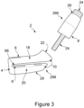
- the clamping mechanism 12 is a live spring formed by the body portion 4 and the pair of arms 10 of the elongate neck part 8.
- the clamping mechanism 12 can be used to lock the proximal end of the reamer 5 within the bore 6, so as to prevent movement of the reamer 5 with respect to the trial neck 2 and/or inadvertent decoupling of the trial neck 2 from the reamer 5.
- the trial neck 2 also comprises an actuator 24 for moving the clamping mechanism 12 between a clamping configuration and a non-clamping configuration.
- the pair of arms 10 of the elongate neck part 8 are pinched together to cause an inner wall 16 of the bore 6 to urge against the reamer 5 to retain the proximal end of the reamer 5 within the bore 6.
- the pair of arms 10 includes a superior arm 18 and an inferior arm 20.
- the pair of arms 10 are positioned such that one arm is located on either side of the gap 66 in the bore annulus. As shown in Figures 1 to 3 , the gap 66 can be transverse to the bore axis.
- the actuator 24 can be a threaded actuation member which causes the clamping mechanism 12 to move into the clamping configuration as the actuator 24 is threaded through the actuator bore 22.
- the actuator bore 22 may extend through the pair of arms 10.
- the actuator bore 22 may include a corresponding thread for cooperation with the thread of the actuator 24.
- the actuator bore 22 may be partially threaded and may be arranged such that the inferior arm 20 may include a threaded portion of the actuator bore 22, while the superior arm 18 may include an unthreaded portion of the actuator bore 22.
- the superior arm 18 may include a threaded portion of the actuator bore 22, while the inferior arm 20 may include an unthreaded portion of the actuator bore 22.
- a proximal end of the actuator 24 may comprise a connection feature for connecting a corresponding connection feature of a tool to the actuator 24 for actuating the actuator 24.
- the actuator 24 may be a screw.
- the actuator bore 22 may extend substantially parallel to the bore 6 for receiving the proximal end of the reamer 5, as shown in Figure 1 .
- the actuator bore 22 may extend from the proximal end 26 to the distal end 28 of the elongate neck part 8 such that the actuator bore 22 extends substantially parallel to a neck axis 3. This is shown for example in Figures 2 and 3 .
- the proximal part 266 of the elongate neck part 8 may be detachable from the distal part 288.
- the elongate neck part 8 may be a single piece with the actuator bore 22 extending substantially parallel to the neck axis 3 in the same way.
- the proximal part 266 is shown in connection with the distal part 288 via the actuator 24.
- Rotation of the actuator 24 within the actuator bore 22 can cause the actuator to move back and forth within the actuator bore 22.
- the actuator 24 is threaded through the partially threaded actuator bore 22, it pulls the inferior arm 16 towards the superior arm 18 which causes the clamping mechanism 12 to move from a non-clamping configuration to a clamping configuration.
- this movement causes the pair of arms 10 of the elongate neck part 8 to pinch together, causing the inner wall 16 of the bore 6 to urge against the reamer 5 thus retaining the proximal end of the reamer 5 within the bore 6.
- Figure 3 shows the proximal part 266 and the actuator 24 detached from the distal part 288 of the elongate neck part 8.
- the actuator 24 is a trial head 30.
- the proximal end 26 of the elongate neck part 8 may include connection feature(s) for connection to complementary features on the trial head 30.
- the embodiments shown in Figures 4 to 6 include a superior arm 18 and an inferior arm 20.
- the pair of arms 10 are positioned such that one arm is located on either side of the gap 66 in the bore annulus. The gap 66 is transverse to the bore axis.
- the trial head 30 of Figure 4 includes a trial head bore 32 which may have a projection 36 located on the inner wall of the bore 32.
- a corresponding recess 34 may be located on the proximal part 266 of the elongate neck part 8.
- the proximal end 26 of the elongate neck part 8 may be formed from a superior arm 18 and an inferior arm 20.
- each of the superior arm 18 and the inferior arm 20 may have a projection 36 for connection with a corresponding recess 34 in the inner bore 32 of the trial head 30.
- the recess 34 could be located on the inner wall of the trial head bore 32
- the projection 36 could be located on the proximal part 266 of the elongate neck part 8.
- Figure 5 shows the recess 34 of the inferior arm 20 in more detail.
- Figure 6 shows the trial neck 2 in the non-clamping configuration, without the trial head 30 attached.
- Figure 4 shows the trial neck 2 in the clamping configuration, with the trial head 30 attached.
- the trial head 30 is connected to the proximal end 26 of the elongate neck part 8, it pinches the inferior arm 16 and superior arm 18 together, decreasing the space between the arms.
- This causes the clamping mechanism 12 to move from a non-clamping configuration to a clamping configuration because as the arms are pinched together, the movement causes the inner wall 16 of the bore 6 to deform, reducing the size of the bore 6.
- the trial head 30 may be attached to the trial neck 2 by pinching together the superior and inferior arms and inserting the proximal end 26 of the elongate neck part 8 into the trial head bore 32 until the projection(s) 36 mates with the recess 34 to hold the trial head 30 in place.
- the recess 34 may have a variable depth along its length such that rotation of the projection(s) 36 within the recess 34 causes the pair of arms 10 of the elongate neck part 8 to be pinched together to a greater or lesser amount relative to the depth of the recess 34.
- the projection(s) 36 can be rotated within the recess 34 by rotating the trial head 30 once the projection(s) have mated with the recess 34.
- Figure 7 shows a different embodiment having an anterior arm 52 and a posterior arm 54.
- the distal end 28 of the pair of arms 10 extend around the bore 6 to join with the body portion 4 such that the bore 6 for receiving the proximal end of the reamer 5 passes through the pair of arms 10.
- the pair of arms 10 are positioned such that one arm is located on either side of the gap 666 in the bore annulus.
- the gap 666 is a longitudinal gap 666, extending the length of the bore (parallel to the bore axis).
- a head attachment portion 40 for attachment to a trial head (not shown) forms the proximal part 266 of the elongate neck part 8.
- the connection of the proximal part 266 with the distal part 288 causes the clamping mechanism 12 to move from a non-clamping configuration to a clamping configuration. As previously described, this movement causes the inner wall 16 of the bore 6 to urge against the reamer 5 thus retaining the proximal end of the reamer 5 within the bore 6.
- the proximal end 42 of the distal part 288 comprises a threaded actuator 24 in the form of a head attachment portion 40 of the elongate neck part 8.
- the threaded actuator 24 includes threads on the outer surface of the anterior and posterior arms 52, 54.
- the head attachment portion 40 comprises an actuator bore 22 at its distal end.
- the actuator bore may contain a corresponding thread on its inner wall 44, for mating with the threaded actuator 24 on the pair of arms 10.
- the proximal end 42 of the distal part 288 can be inserted into the actuator bore of the proximal part 266, and rotation of the head attachment portion 40 causes the clamping mechanism 12 to move from a non-clamping configuration to a clamping configuration due to the engagement of the threaded components.
- FIG. 8 An alternative embodiment is shown in Figure 8 , this embodiment also includes an anterior arm 52 and a posterior arm 54.
- the distal end 28 of the pair of arms 10 extend around the bore 6 to join with the body portion 4 such that the bore 6 for receiving the proximal end of the reamer 5 may pass through the pair of arms 10.
- the pair of arms 10 and the body portion 4 form the distal part 288 of the trial neck 2.
- a head attachment portion 40, for attachment to a trial head (not shown) forms the proximal part 266 of the elongate neck part 8.
- the pair of arms 10 are positioned such that one arm is located on either side of the gap 666, which extends the length of the bore (parallel to the bore axis).
- the proximal end 42 of the distal part 288 comprises at least one protrusion 46 on an outer surface of the pair of arms 10.
- the head attachment portion 40 comprises an actuator bore 22 at its distal end.
- At least one protrusion 48 may also extend from an inner wall 44 of the actuator bore 22.
- a distal surface 50 of the at least one protrusion 46 on the proximal end 42 of the distal part 288 abuts a proximal surface 53 of the at least one protrusion 48 on the proximal part 266.
- attachment of the proximal part 266 to the distal part 288 causes the pair of arms 10 to pinch together to move the clamping mechanism 12 from a non-clamping configuration to a clamping configuration.
- this movement causes the inner wall 16 of the bore 6 to urge against the reamer 5 thus retaining the proximal end of the reamer 5 within the bore 6.
- a surgical kit comprising a trial neck (for example a trial neck 2 of the kind described above) and a reamer 5.
- the surgical kit may further comprise a trial head 30 having a bore 32 for receiving the proximal end 266 of the elongate neck part 8 to releasably attach the trial head 30 to the trial neck 2.
- the kit may include further components (e.g. one or more differently sized trial necks of the kind described above, one or more different kinds of reamer 5, one or more trial heads, and/or any other components).
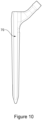
- An exemplary reamer 5 is shown in Figures 9 and 10 . Note that the geometry of the proximal end of the reamer 5 illustrates one of many examples which may be used with the neck trial 2 of the present disclosure.
- Figure 10 shows an exemplary femoral stem 70 prosthetic component which may be inserted following preparation of the femur using any embodiments listed above.
- a trial neck for example a trial neck 2 of the kind described above
- a reamer 5 for example a reamer 5
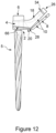
- the method may include a step 301 of inserting the proximal end of a reamer 5 into the bore 6 of the trial neck 2, as shown in Figure 12 .
- the method may also include connecting a tool to a connection feature on the actuator 24 for actuating the actuator 24.
- a tool such as a screwdriver may be used when the actuator 24 is a screw.
- the method may include a step 302 of using the actuator 24 to pinch the pair of arms 10 of the elongate neck part 8 together to cause an inner wall 16 of the bore 6 to urge against the reamer 5.
- step 303 the user can check whether the inner wall 16 of the bore 6 is urged against the reamer 5. It may be necessary to repeat step 302 until the actuator has sufficiently pinched together the pair of arms 10 enough to urge the inner wall 16 of the bore 6 against the reamer 5 so that the reamer 5 is attached to the trial neck 2.
- the actuator may comprise a trial head 30.
- step 302 of the method may include placing a trial head 30 over the proximal end 266 of the elongate neck part 8 to pinch together the pair of arms 10 of the elongate neck part 8.
- the method may include rotating the trial head 30 to rotate a projection 36 within a recess 34 to cause the pair of arms 10 of the elongate neck part 8 to pinch together.
- the actuator may comprise a proximal part 266.
- step 302 of the method may include attaching a proximal part 266 to a distal part 288 to position a distal surface 50 of at least one protrusion 46 on the proximal end 42 of the distal part 288 in abutment with a proximal surface 53 of at least one protrusion 48 on the proximal part 266 to cause the pair of arms 10 to pinch together.
- the trial neck includes a body portion having a bore for receiving a proximal end of the bone canal preparation instrument.
- the trial neck also includes an elongate neck part comprising a pair of arms extending from the body portion.
- the trial neck further includes a clamping mechanism comprising a live spring formed by the body portion and said pair of arms of the elongate neck part and an actuator, for moving the clamping mechanism between a clamping configuration and a non-clamping configuration. In the clamping configuration, the pair of arms of the elongate neck part are pinched together to cause an inner wall of the bore to urge against the bone canal preparation instrument to retain the proximal end of the bone canal preparation instrument within the bore.
Landscapes
- Health & Medical Sciences (AREA)
- Orthopedic Medicine & Surgery (AREA)
- Transplantation (AREA)
- Vascular Medicine (AREA)
- Animal Behavior & Ethology (AREA)
- Engineering & Computer Science (AREA)
- Biomedical Technology (AREA)
- Heart & Thoracic Surgery (AREA)
- Cardiology (AREA)
- Life Sciences & Earth Sciences (AREA)
- Oral & Maxillofacial Surgery (AREA)
- General Health & Medical Sciences (AREA)
- Public Health (AREA)
- Veterinary Medicine (AREA)
- Physical Education & Sports Medicine (AREA)
- Prostheses (AREA)
- Diaphragms For Electromechanical Transducers (AREA)
Description
- The present specification relates to a trial component for orthopaedic surgery. In particular, a trial femoral neck for orthopaedic surgery. This disclosure also relates to a kit including one or more trial components, and instruments for orthopaedic surgery. This disclosure also relates to a method of attaching a trail neck to a bone canal preparation instrument.
- Hip replacement is a surgical procedure in which the hip joint is replaced by artificial joint components, also referred to generally as prostheses or implants. Total replacement of the hip joint involves installing an acetabular cup implant in the acetabulum of a patient and installing a prosthetic in the femur of the patient. Joint replacement surgery can also be performed in other joints, such as the shoulder.
- For hip replacement surgery, the prosthetic typically includes a femoral stem, which is received in the medullary canal of the femur, and a femoral head having a bearing surface which is received in the acetabulum or acetabular cup implant. The prosthetic typically also includes a femoral neck which extends between a proximal end of the stem and the head.
- Successful hip replacement surgery requires correct positioning and alignment of the acetabular cup implant as well as the prosthetic itself. Misalignment and/or the selection of an inappropriately sized acetabular cup implant and/or the prosthetic may result in restricted movement of the prosthetic and/or accelerated wear and tear of the bearing surfaces of the acetabular cup implant and the bearing surface of the head. Various factors are involved in achieving this correct positioning and alignment. At least some of these factors relate to the neck of the prosthetic. These factors may include, for instance, the length of the neck, and an angular orientation (offset) of the neck relative to the stem. Trialling may be used during such orthopaedic procedures in order to help assess the patient's needs.
- Trialling can be used during primary or complex primary and revision surgeries. During trialling, the surgeon uses trial components, rather than the actual implants, to help assess whether any changes might be made to bone cuts and/or soft tissues and/or the implants originally planned to be used. It can be more efficient to utilise a bone canal preparation instrument as one of these components.
- During a primary hip or shoulder arthroplasty procedure, various sizes of broach or other bone canal preparation instruments may be used to prepare the medullary canal of the femur or humerus. Once the bone canal preparation instrument is inserted into the bone, a trial neck and trial head may also be attached to the bone canal preparation instrument, in order to evaluate whether a prosthetic having a neck and head of that type (e.g. in terms of the size and offset of the neck) would be appropriate for the patient.
- Conventionally trial necks are connected to the spigot of the bone canal preparation instrument by the use of an O-ring. The O-ring forms an interference fit or friction fit when it arranged between the spigot and the internal surface of the trial neck.
- After the surgeon is satisfied that the chosen combination of bone canal preparation instrument, trial neck and trial head are correctly positioned and aligned, they may be removed and replaced with the implant itself.
- Occasionally revision arthroplasty surgery may need to be performed on a patient. In such a revision surgery, the previously implanted prosthesis is surgically removed, and a replacement prosthesis is implanted. In some revision surgeries, all of the components of the previously implanted hip prosthesis, including, for example, the femoral stem, neck component, and the acetabular cup, may be surgically removed. In other revision surgeries, only part of the previously implanted prosthesis may be removed and replaced.
-
WO2019068428A1 describes a trial neck and a method for trialling a neck of an orthopaedic implant in a hip replacement procedure. The method includes inserting a broach into a medullary canal of a femur of a patient. The method also includes connecting a distal end of a trial neck to a proximal end of the broach. The trial neck includes a proximal end connectable to a trial head. The trial neck further includes a body portion extending along a neck axis of the trial neck between the distal end and the proximal end. The trial neck also includes also includes a resilient retaining member configured to engage a surface of the broach when the trial neck is connected to the broach, for inhibiting removal of the trial neck from the broach. The method further includes engaging the resilient retaining member with the surface of the broach. - Aspects of the present invention are set out in the accompanying independent and dependent claims. Combinations of features from the dependent claims may be combined with features of the independent claims as appropriate and not merely as explicitly set out in the claims.
- According to a first aspect of this invention there is provided a trial neck for releasable attachment to a bone canal preparation instrument, the trial neck comprising:
- a body portion having a bore for receiving a proximal end of the bone canal preparation instrument;
- an elongate neck part comprising a pair of arms extending from the body portion;
- a clamping mechanism comprising a live spring formed by the body portion and said pair of arms of the elongate neck part; and
- an actuator, for moving the clamping mechanism between a clamping configuration and a non-clamping configuration,
- The pinching together of the pair of arms can narrow and/or distort the bore so that it can grip the proximal end of the bone canal preparation instrument to provide a secure attachment of the trial neck to the bone canal preparation instrument.
- The clamping mechanism may allow the trial neck to be attached to a bone canal preparation instrument in a variety of orientations e.g. around a longitudinal axis of the bone canal preparation instrument.
- The pair of arms may extend from the elongate neck part into the body portion, and the bore for receiving the proximal end of the bone canal preparation instrument may pass through the pair of arms.
- The bore may be defined by a bore annulus and the pair of arms may be positioned such that an arm is located on either side of a break in the bore annulus. The break in the bore annulus promotes distortion of the bore when the pair of arms are pinched together.
- The pair of arms may comprise a superiorly located arm and an inferiorly located arm.
- The trial neck may further include a partially threaded actuator bore which extends through the pair of arms. The partially threaded actuator bore may be arranged such that one of the superior or inferior arm may comprise an unthreaded portion of the actuator bore, and the other of the superior or inferior arm comprises a threaded portion of the actuator bore. The actuator may comprise a threaded actuation member extending within the partially threaded actuator bore. The threaded actuator can provide a convenient way of operating the clamping mechanism. Further, the threaded actuator can allow fine adjustments to be made to the size of the bore for receiving the proximal end of the bone canal preparation instrument.
- The actuator bore may extend substantially parallel to the bore for receiving the proximal end of the bone canal preparation instrument.
- The elongate neck part may also comprise a proximal end; a distal end; and a neck axis extending between the proximal and distal ends. The actuator bore may extend from the proximal end to the distal end of the elongate neck part such that the actuator bore extends substantially parallel to a neck axis. This can allow the surgeon to have improved accessibility to the actuator bore when the actuator bore extends from the proximal end of the elongate neck part.
- The elongate neck part may also comprise a proximal part, a distal part, and a neck axis extending between the proximal and distal parts. The distal part may comprise the pair of arms. The threaded actuator bore and threaded actuation member may be substantially parallel to the neck axis. The proximal part may be detachable from the distal part, wherein attachment of the proximal part onto the distal part causes the pair of arms of the elongate neck part to be pinched together to cause an inner wall of the bore to urge against the bone canal preparation instrument to retain the proximal end of the bone canal preparation instrument within the bore. This can allow the surgeon to have improved accessibility to the actuator bore when the actuator bore extends from the proximal end of the elongate neck part.
- The actuator may comprise a trial head having a bore for connection to the trial neck, wherein attachment of the trial head over the proximal end of the elongate neck part causes the pair of arms of the elongate neck part to be pinched together to cause an inner wall of the bore to urge against the bone canal preparation instrument to retain the proximal end of the bone canal preparation instrument within the bore. This can reduce the number of parts needed to form the trial since there is no need for a separate actuation member.
- The pair of arms may include a recess for engagement with a corresponding projection inside the bore of the trial head, wherein the recess has a variable depth along its length, and wherein rotation of the projection within the recess causes the pair of arms of the elongate neck part to be pinched together to cause an inner wall of the bore to urge against the bone canal preparation instrument to retain the proximal end of the bone canal preparation instrument within the bore. The recess allows the user to adjust the level of pinching by the arms, and so adjust the size of the bore for receiving the bone canal preparation instrument. This can reduce the number of parts needed to form the trial since there is no need for a separate actuation member. The rotation of projections within the recess is a convenient way of operating the clamping mechanism and using the trial head as the actuator can provide for an easily accessible mechanism for a surgeon.
- The elongate neck part may comprise;
- a proximal part and a distal part;
- wherein the proximal part comprises a head attachment portion and an actuator bore;
- wherein the distal part comprises the pair of arms, wherein the arms extend from the body portion, and wherein the bore for receiving the proximal end of the bone canal preparation instrument passes through the pair of arms,
- This can provide increased leverage, because the arms are pinched together at the proximal end of the arms.
- The pair of arms may be threaded at a proximal end of the distal part for connection to a corresponding thread on an inner wall of the actuator bore of the proximal part. This can provide for a secure connection between the distal and proximal parts.
- The proximal end of the distal part may comprise at least one protrusion on an outer surface of the pair of arms. At least one protrusion may extend from an inner wall of the actuator bore. When assembled, a distal surface of the at least one protrusion on the proximal end of the distal part may abut a proximal surface of the at least one protrusion on the proximal part. Attachment of the proximal part to the distal part may cause the pair of arms to pinch together to cause an inner wall of the bore to urge against the bone canal preparation instrument to retain the proximal end of the bone canal preparation instrument within the bore. This mechanism can allow the user to quickly attach the proximal part to the distal part whilst activating the clamping mechanism.
- The pair of arms may comprise an anteriorly located arm and a posteriorly located arm.
- According to another aspect of the invention, there is provided a surgical kit comprising:
- a trial neck; and
- a bone canal preparation instrument.
- The surgical kit may further comprise a trial head having a bore for receiving the proximal end of the elongate neck part to releasably attach the trial head to the trial neck. The surgical kit may further comprise a prosthetic stem component.
- According to a further aspect of this disclosure, there is provided a method of attaching a trial neck to a bone canal preparation instrument, the trial neck comprising:
- a body portion having a bore for receiving a proximal end of the bone canal preparation instrument;
- an elongate neck part comprising a pair of arms extending from the body portion;
- a clamping mechanism comprising a live spring formed by the body portion and said pair of arms of the elongate neck part; and
- an actuator, for moving the clamping mechanism between a clamping configuration and a non-clamping configuration,
- The pinching together of the pair of arms narrows the bore to provide a secure attachment of the trial neck onto the bone canal preparation instrument without the need for the bone canal preparation instrument to be at a specific angle or position. The trial neck can therefore be attached to a bone canal preparation instrument in a variety of orientations.
- The pair of arms of the trial neck may extend from the elongate neck part into the body portion. The bore for receiving the proximal end of the bone canal preparation instrument may pass through the pair of arms.
- The bore may be defined by a bore annulus and the pair of arms may be positioned such that an arm is located on either side of a break in the bore annulus. The break in the bore annulus promotes distortion of the bore when the pair of arms are pinched together. This allows retention of the proximal end of the reamer by both axial tension and torsional forces.
- The break in the bore annulus may be transverse to the bore axis, or may be a longitudinal break, extending the length of the bore (parallel to the bore axis). A transverse break promotes distortion of the bore and provides axial tension against the proximal end of the reamer. A longitudinal break promotes distortion of the bore and provides torsional tension against the proximal end of the reamer. Both the transverse and longitudinal beaks provide a degree of axial tension and torsional forces.
- The pair of arms may comprise a superiorly located arm and an inferiorly located arm.
- A partially threaded actuator bore may extend through the pair of arms. The partially threaded actuator bore may be arranged such that one of the pair of arms may include a threaded portion of the actuator bore, while the other arm may include an un-threaded portion of the actuator bore. The actuator may comprise a threaded actuation member extending within the threaded actuator bore. The threaded actuator can provide a convenient way of operating the clamping mechanism. Further, the threaded actuator can allow fine adjustments to be made to the size of the bore for receiving the proximal end of the bone canal preparation instrument.
- The actuator bore may extend substantially parallel to the bore for receiving the proximal end of the bone canal preparation instrument.
- The elongate neck part may comprise:
- a proximal end;
- a distal end; and
- a neck axis extending between the proximal and distal ends,
- wherein the actuator bore extends from the proximal end to the distal end of the elongate neck part such that the actuator bore extends substantially parallel to a neck axis.
- The elongate neck part may comprise:
- a proximal part, a distal part, and a neck axis extending between the proximal and distal parts;
- wherein the distal part comprises the pair of arms;
- wherein the threaded actuator bore and threaded actuation member are substantially parallel to the neck axis; and
- wherein the proximal part is detachable from the distal part, wherein attachment of the proximal part onto the distal part causes the pair of arms of the elongate neck part to be pinched together to cause an inner wall of the bore to urge against the bone canal preparation instrument to retain the proximal end of the bone canal preparation instrument within the bore.
- The actuator may comprise a trial head having a bore for connection to the trial neck. The method may further comprise placing the trial head over the proximal end of the elongate neck part to pinch together the pair of arms of the elongate neck part, causing an inner wall of the bore to urge against the bone canal preparation instrument to retain the proximal end of the bone canal preparation instrument within the bore.
- The pair of arms may include a recess for engagement with a corresponding projection inside the bore of the trial head. The recess may have a variable depth along its length. The method may further comprise rotating the trial head to rotate the projection within the recess to cause the pair of arms of the elongate neck part to pinch together to cause an inner wall of the bore to urge against the bone canal preparation instrument to retain the proximal end of the bone canal preparation instrument within the bore.
- The elongate neck part may comprise;
- a proximal part and a distal part;
- wherein the proximal part comprises a head attachment portion and an actuator bore;
- wherein the distal part comprises the pair of arms, wherein the arms extend from the body portion, and wherein the bore for receiving the proximal end of the bone canal preparation instrument passes through the pair of arms,
- wherein the proximal part of the elongate neck part is detachable from the distal part. The method may further comprise attaching the proximal part to the distal part to pinch together the pair of arms to cause an inner wall of the bore to urge against the bone canal preparation instrument to retain the proximal end of the bone canal preparation instrument within the bore.
- The pair of arms may be threaded at a proximal end of the distal part for connection to a corresponding thread on an inner wall of the actuator bore of the proximal part.
- The proximal end of the distal part may comprise at least one protrusion on an outer surface of the pair of arms. At least one protrusion may extend from an inner wall of the actuator bore. The method may further comprise attaching the proximal part to the distal part to position a distal surface of the at least one protrusion on the proximal end of the distal part in abutment with a proximal surface of the at least one protrusion on the proximal part to cause the pair of arms to pinch together to cause an inner wall of the bore to urge against the bone canal preparation instrument to retain the proximal end of the bone canal preparation instrument within the bore.
- The pair of arms may comprise an anteriorly located arm and a posteriorly located arm.
- Embodiments of this disclosure will be described hereinafter, by way of example only, with reference to the accompanying drawings in which like reference signs relate to like elements and in which:
-
Figure 1 shows an anterior view of a trial neck, according to an embodiment of this disclosure; -
Figure 2 shows an anterior view of a trial neck, according to another embodiment of this disclosure; -
Figure 3 shows an anterior view of the trial neck ofFigure 2 with the proximal part detached from the distal part; -
Figure 4 shows a cross section of a trial neck, according to a further embodiment of this disclosure; -
Figure 5 shows an inferior view of the trial neck ofFigure 4 ; -
Figure 6 shows an anterior view of the trial neck ofFigure 4 with the trial head removed; -
Figure 7 shows a trial neck according to another embodiment of the disclosure; -
Figure 8 shows a trial neck according to another embodiment of the disclosure; -
Figure 9 shows an exemplary reamer; -
Figure 10 shows an exemplary femoral stem prosthetic; -
Figure 11 is a flow chart showing the method according to another embodiment of the disclosure; and -
Figure 12 shows an exemplary reamer attached to the trial neck ofFigure 6 . - Embodiments of this disclosure are described in the following with reference to the accompanying drawings.
- Referring to
Figures 1 to 8 there is shown a trial neck. Thetrial neck 2 has abody portion 4. Thebody portion 4 includes abore 6. Thebore 6 may be a blind bore (closed at its proximal end), although in the embodiments shown in the Figures it is an open bore, which passes completely through thebody portion 4. Thebore 6 can receive the proximal end of a bone canal preparation instrument, for attaching the bone canal preparation instrument to thetrial neck 2. - The bone canal preparation instrument may, for example, be a trial stem, or a cutting instrument such as a reamer or a broach. In the following description, the bone canal preparation instrument comprises a
reamer 5, but it will be appreciated that in other examples, the bone canal preparation instrument may be one of the other instruments noted above. Anexemplary reamer 5 is shown inFigure 9 . - The
reamer 5 itself may be in the form of an elongate shaft and may have a cutting surface located distally. Thereamer 5 has a proximal end located proximally with respect to the cutting surface. The proximal end may be substantially cylindrical, with a circular cross section, although this is not essential. The proximal end may be inserted into thebore 6 of thetrial neck 2 for attaching thereamer 5 to thetrial neck 2, as will be described in more detail below. - As shown in
Figures 1 to 8 , thetrial neck 2 also has anelongate neck part 8. Theelongate neck part 8 extends from thebody portion 4. Theelongate neck part 8 has aproximal end 26 and adistal end 28 and aneck axis 3 which extends between the proximal 26 and distal ends 28. - A
proximal end 26 of theelongate neck part 8 may be configured to be attached to atrial head 30. In other examples, thetrial head 30 may be integral with the trial neck 2 (not shown). - The
elongate neck part 8 includes a pair ofarms 10 extending from thebody portion 4. The pair of arms extend from theelongate neck part 8 and around thebore 6 to join with thebody portion 4 such that thebore 6 for receiving the proximal end of thereamer 5 may pass through the pair ofarms 10. - The
bore 6 is defined by a bore annulus. The bore annulus is broken, such that there is agap 66 in the wall of the bore which may extend the length of thebore 6. The pair of arms are positioned such that one arm is located on either side of a break in the bore annulus. The break in the bore annulus promotes distortion of thebore 6 when the pair ofarms 10 are pinched together. - The
trial neck 2 comprises aclamping mechanism 12 for attaching the proximal end of thereamer 5 to thetrial neck 2. Theclamping mechanism 12 is a live spring formed by thebody portion 4 and the pair ofarms 10 of theelongate neck part 8. Theclamping mechanism 12 can be used to lock the proximal end of thereamer 5 within thebore 6, so as to prevent movement of thereamer 5 with respect to thetrial neck 2 and/or inadvertent decoupling of thetrial neck 2 from thereamer 5. - The
trial neck 2 also comprises anactuator 24 for moving theclamping mechanism 12 between a clamping configuration and a non-clamping configuration. In the clamping configuration, the pair ofarms 10 of theelongate neck part 8 are pinched together to cause aninner wall 16 of thebore 6 to urge against thereamer 5 to retain the proximal end of thereamer 5 within thebore 6. - Specific features of the different embodiments of this disclosure will now be discussed separately and in more detail, in which like features are indicated with like reference numerals.
- In the embodiment shown in
Figures 1 to 3 , the pair ofarms 10 includes asuperior arm 18 and aninferior arm 20. The pair ofarms 10 are positioned such that one arm is located on either side of thegap 66 in the bore annulus. As shown inFigures 1 to 3 , thegap 66 can be transverse to the bore axis. - As may be appreciated from
Figures 1 to 3 , theactuator 24 can be a threaded actuation member which causes theclamping mechanism 12 to move into the clamping configuration as theactuator 24 is threaded through the actuator bore 22. The actuator bore 22 may extend through the pair ofarms 10. The actuator bore 22 may include a corresponding thread for cooperation with the thread of theactuator 24. The actuator bore 22 may be partially threaded and may be arranged such that theinferior arm 20 may include a threaded portion of the actuator bore 22, while thesuperior arm 18 may include an unthreaded portion of the actuator bore 22. Alternatively, thesuperior arm 18 may include a threaded portion of the actuator bore 22, while theinferior arm 20 may include an unthreaded portion of the actuator bore 22. A proximal end of theactuator 24 may comprise a connection feature for connecting a corresponding connection feature of a tool to theactuator 24 for actuating theactuator 24. - As shown in
Figures 1 to 3 , theactuator 24 may be a screw. - The actuator bore 22 may extend substantially parallel to the
bore 6 for receiving the proximal end of thereamer 5, as shown inFigure 1 . Alternatively, the actuator bore 22 may extend from theproximal end 26 to thedistal end 28 of theelongate neck part 8 such that the actuator bore 22 extends substantially parallel to aneck axis 3. This is shown for example inFigures 2 and3 . In this embodiment, theproximal part 266 of theelongate neck part 8 may be detachable from thedistal part 288. Alternatively, theelongate neck part 8 may be a single piece with the actuator bore 22 extending substantially parallel to theneck axis 3 in the same way. - In
Figure 2 , theproximal part 266 is shown in connection with thedistal part 288 via theactuator 24. Rotation of theactuator 24 within the actuator bore 22 (for example using a tool) can cause the actuator to move back and forth within the actuator bore 22. As theactuator 24 is threaded through the partially threaded actuator bore 22, it pulls theinferior arm 16 towards thesuperior arm 18 which causes theclamping mechanism 12 to move from a non-clamping configuration to a clamping configuration. As previously described, this movement causes the pair ofarms 10 of theelongate neck part 8 to pinch together, causing theinner wall 16 of thebore 6 to urge against thereamer 5 thus retaining the proximal end of thereamer 5 within thebore 6.Figure 3 shows theproximal part 266 and theactuator 24 detached from thedistal part 288 of theelongate neck part 8. - In the embodiments shown in
Figures 4 to 6 , theactuator 24 is atrial head 30. Theproximal end 26 of theelongate neck part 8 may include connection feature(s) for connection to complementary features on thetrial head 30. The embodiments shown inFigures 4 to 6 include asuperior arm 18 and aninferior arm 20. The pair ofarms 10 are positioned such that one arm is located on either side of thegap 66 in the bore annulus. Thegap 66 is transverse to the bore axis. - The
trial head 30 ofFigure 4 includes a trial head bore 32 which may have aprojection 36 located on the inner wall of thebore 32. A correspondingrecess 34 may be located on theproximal part 266 of theelongate neck part 8. In this embodiment, theproximal end 26 of theelongate neck part 8 may be formed from asuperior arm 18 and aninferior arm 20. As such each of thesuperior arm 18 and theinferior arm 20 may have aprojection 36 for connection with acorresponding recess 34 in theinner bore 32 of thetrial head 30. Alternatively, therecess 34 could be located on the inner wall of the trial head bore 32, and theprojection 36 could be located on theproximal part 266 of theelongate neck part 8. There may be asingle projection 36 or two ormore projections 36. -
Figure 5 shows therecess 34 of theinferior arm 20 in more detail. - The effect of the
clamping mechanism 12 can be seen by comparingFigures 4 and6. Figure 6 shows thetrial neck 2 in the non-clamping configuration, without thetrial head 30 attached.Figure 4 shows thetrial neck 2 in the clamping configuration, with thetrial head 30 attached. As thetrial head 30 is connected to theproximal end 26 of theelongate neck part 8, it pinches theinferior arm 16 andsuperior arm 18 together, decreasing the space between the arms. This causes theclamping mechanism 12 to move from a non-clamping configuration to a clamping configuration because as the arms are pinched together, the movement causes theinner wall 16 of thebore 6 to deform, reducing the size of thebore 6. - In one embodiment, the
trial head 30 may be attached to thetrial neck 2 by pinching together the superior and inferior arms and inserting theproximal end 26 of theelongate neck part 8 into the trial head bore 32 until the projection(s) 36 mates with therecess 34 to hold thetrial head 30 in place. - In another embodiment, the
recess 34 may have a variable depth along its length such that rotation of the projection(s) 36 within therecess 34 causes the pair ofarms 10 of theelongate neck part 8 to be pinched together to a greater or lesser amount relative to the depth of therecess 34. The projection(s) 36 can be rotated within therecess 34 by rotating thetrial head 30 once the projection(s) have mated with therecess 34. -
Figure 7 shows a different embodiment having ananterior arm 52 and aposterior arm 54. As with previously described embodiments, thedistal end 28 of the pair ofarms 10 extend around thebore 6 to join with thebody portion 4 such that thebore 6 for receiving the proximal end of thereamer 5 passes through the pair ofarms 10. The pair ofarms 10 are positioned such that one arm is located on either side of thegap 666 in the bore annulus. In this embodiment, thegap 666 is alongitudinal gap 666, extending the length of the bore (parallel to the bore axis). - A
head attachment portion 40, for attachment to a trial head (not shown) forms theproximal part 266 of theelongate neck part 8. The connection of theproximal part 266 with thedistal part 288 causes theclamping mechanism 12 to move from a non-clamping configuration to a clamping configuration. As previously described, this movement causes theinner wall 16 of thebore 6 to urge against thereamer 5 thus retaining the proximal end of thereamer 5 within thebore 6. - As shown in
Figure 7 , theproximal end 42 of thedistal part 288 comprises a threadedactuator 24 in the form of ahead attachment portion 40 of theelongate neck part 8. The threadedactuator 24 includes threads on the outer surface of the anterior andposterior arms head attachment portion 40 comprises an actuator bore 22 at its distal end. The actuator bore may contain a corresponding thread on itsinner wall 44, for mating with the threadedactuator 24 on the pair ofarms 10. Theproximal end 42 of thedistal part 288 can be inserted into the actuator bore of theproximal part 266, and rotation of thehead attachment portion 40 causes theclamping mechanism 12 to move from a non-clamping configuration to a clamping configuration due to the engagement of the threaded components. - An alternative embodiment is shown in
Figure 8 , this embodiment also includes ananterior arm 52 and aposterior arm 54. As with previously described embodiments, thedistal end 28 of the pair ofarms 10 extend around thebore 6 to join with thebody portion 4 such that thebore 6 for receiving the proximal end of thereamer 5 may pass through the pair ofarms 10. The pair ofarms 10 and thebody portion 4 form thedistal part 288 of thetrial neck 2. Ahead attachment portion 40, for attachment to a trial head (not shown) forms theproximal part 266 of theelongate neck part 8. - In the embodiment of
Figure 8 , the pair ofarms 10 are positioned such that one arm is located on either side of thegap 666, which extends the length of the bore (parallel to the bore axis). - As shown in
Figure 8 , theproximal end 42 of thedistal part 288 comprises at least oneprotrusion 46 on an outer surface of the pair ofarms 10. Thehead attachment portion 40 comprises an actuator bore 22 at its distal end. At least oneprotrusion 48 may also extend from aninner wall 44 of the actuator bore 22. When assembled, adistal surface 50 of the at least oneprotrusion 46 on theproximal end 42 of thedistal part 288 abuts aproximal surface 53 of the at least oneprotrusion 48 on theproximal part 266. As such, attachment of theproximal part 266 to thedistal part 288 causes the pair ofarms 10 to pinch together to move theclamping mechanism 12 from a non-clamping configuration to a clamping configuration. As previously described, this movement causes theinner wall 16 of thebore 6 to urge against thereamer 5 thus retaining the proximal end of thereamer 5 within thebore 6. - According to an embodiment of this disclosure, there may be provided a surgical kit comprising a trial neck (for example a
trial neck 2 of the kind described above) and areamer 5. The surgical kit may further comprise atrial head 30 having abore 32 for receiving theproximal end 266 of theelongate neck part 8 to releasably attach thetrial head 30 to thetrial neck 2. It is envisaged that the kit may include further components (e.g. one or more differently sized trial necks of the kind described above, one or more different kinds ofreamer 5, one or more trial heads, and/or any other components). Anexemplary reamer 5 is shown inFigures 9 and10 . Note that the geometry of the proximal end of thereamer 5 illustrates one of many examples which may be used with theneck trial 2 of the present disclosure. -
Figure 10 shows an exemplary femoral stem 70 prosthetic component which may be inserted following preparation of the femur using any embodiments listed above. - According to a further embodiment of this disclosure, there may be provided a method of attaching a trial neck (for example a
trial neck 2 of the kind described above) to areamer 5, as shown in the flow chart ofFigure 11 . - The method may include a
step 301 of inserting the proximal end of areamer 5 into thebore 6 of thetrial neck 2, as shown inFigure 12 . - The method may also include connecting a tool to a connection feature on the
actuator 24 for actuating theactuator 24. For example, a tool such as a screwdriver may be used when theactuator 24 is a screw. - The method may include a
step 302 of using theactuator 24 to pinch the pair ofarms 10 of theelongate neck part 8 together to cause aninner wall 16 of thebore 6 to urge against thereamer 5. - In a
subsequent step 303, the user can check whether theinner wall 16 of thebore 6 is urged against thereamer 5. It may be necessary to repeatstep 302 until the actuator has sufficiently pinched together the pair ofarms 10 enough to urge theinner wall 16 of thebore 6 against thereamer 5 so that thereamer 5 is attached to thetrial neck 2. - The actuator may comprise a
trial head 30. As such, step 302 of the method may include placing atrial head 30 over theproximal end 266 of theelongate neck part 8 to pinch together the pair ofarms 10 of theelongate neck part 8. The method may include rotating thetrial head 30 to rotate aprojection 36 within arecess 34 to cause the pair ofarms 10 of theelongate neck part 8 to pinch together. - The actuator may comprise a
proximal part 266. As such, step 302 of the method may include attaching aproximal part 266 to adistal part 288 to position adistal surface 50 of at least oneprotrusion 46 on theproximal end 42 of thedistal part 288 in abutment with aproximal surface 53 of at least oneprotrusion 48 on theproximal part 266 to cause the pair ofarms 10 to pinch together. - Accordingly, there has been described a trial neck for hip surgery and a method of attaching a trial neck to a bone canal preparation instrument. The trial neck includes a body portion having a bore for receiving a proximal end of the bone canal preparation instrument. The trial neck also includes an elongate neck part comprising a pair of arms extending from the body portion. The trial neck further includes a clamping mechanism comprising a live spring formed by the body portion and said pair of arms of the elongate neck part and an actuator, for moving the clamping mechanism between a clamping configuration and a non-clamping configuration. In the clamping configuration, the pair of arms of the elongate neck part are pinched together to cause an inner wall of the bore to urge against the bone canal preparation instrument to retain the proximal end of the bone canal preparation instrument within the bore.
- Although particular embodiments of this disclosure have been described, it will be appreciated that many modifications/additions and/or substitutions may be made within the scope of the claims.
inserting the proximal end of the bone canal preparation instrument into the bore; and
using the actuator to pinch the pair of arms of the elongate neck part together to cause an inner wall of the bore to urge against the bone canal preparation instrument.
Claims (19)
- A trial neck (2) for releasable attachment to a bone canal preparation instrument, the trial neck comprising:a body portion (4) having a bore (6) for receiving a proximal end of the bone canal preparation instrument (5);an elongate neck part (8) comprising a pair of arms (10) extending from the body portion (4); anda clamping mechanism (12) comprising a live spring formed by the body portion (4) and said pair of arms (10) of the elongate neck part; characterised in that the trial neck further comprisesan actuator (24), for moving the clamping mechanism (12) between a clamping configuration and a non-clamping configuration,wherein in the clamping configuration, the pair of arms (10) of the elongate neck part are pinched together to cause an inner wall (16) of the bore to urge against the bone canal preparation instrument (5) to retain the proximal end of the bone canal preparation instrument within the bore (6).
- The trial neck (2) of claim 1, wherein the pair of arms (10) extend from the elongate neck part (8) into the body portion (4), and wherein the bore (6) for receiving the proximal end of the bone canal preparation instrument passes through the pair of arms, optionally,
wherein the bore (6) is defined by a bore annulus and wherein the pair of arms (10) are positioned such that an arm is located on either side of a break (66) in the bore annulus. - The trial neck (2) of claim 1, wherein the pair of arms (10) comprises a superiorly located arm (18) and an inferiorly located arm (20).
- The trial neck (2) of claim 3, wherein:a partially threaded actuator bore (22) extends through the pair of arms (10);wherein the actuator (24) comprises a threaded actuation member extending within the partially threaded actuator bore (22); andwherein one of the superior or inferior arm (18, 20) comprises an unthreaded portion of the actuator bore (22), and the other of the superior or inferior arm (20, 18) comprises a threaded portion of the actuator bore (22).
- The trial neck (2) of claim 4, wherein the actuator bore (22) extends substantially parallel to the bore (6) for receiving the proximal end of the bone canal preparation instrument,
or,wherein the elongate neck part (8) comprisesa proximal end (26);a distal end (28); anda neck axis (3) extending between the proximal and distal ends,wherein the actuator bore (22) extends from the proximal end to the distal end of the elongate neck part (8) such that the actuator bore (22) extends substantially parallel to a neck axis (3),
or,wherein the elongate neck part (8) comprises;a proximal part (266), a distal part (288), and a neck axis (3) extending between the proximal and distal parts;wherein the distal part (288) comprises the pair of arms (10);wherein the threaded actuator bore (22) and threaded actuation member (24) are substantially parallel to the neck axis (3); andwherein the proximal part (266) is detachable from the distal part, wherein attachment of the proximal part onto the distal part causes the pair of arms (10) of the elongate neck part to be pinched together to cause an inner wall (16) of the bore to urge against the bone canal preparation instrument (5) to retain the proximal end of the bone canal preparation instrument within the bore (6). - The trial neck (2) of claim 1, wherein the actuator comprises a trial head (30) having a bore (32) for connection to the trial neck (2), wherein attachment of the trial head over the proximal end of the elongate neck part causes the pair of arms (10) of the elongate neck part to be pinched together to cause an inner wall (16) of the bore to urge against the bone canal preparation instrument to retain the proximal end of the bone canal preparation instrument within the bore (6), optionally,
wherein the pair of arms (10) include a recess (34) for engagement with a corresponding projection (36) inside the bore (32) of the trial head, wherein the recess has a variable depth along its length, and wherein rotation of the projection within the recess causes the pair of arms (10) of the elongate neck part to be pinched together to cause an inner wall (16) of the bore to urge against the bone canal preparation instrument to retain the proximal end of the bone canal preparation instrument within the bore. - The trial neck (2) of claim 1, wherein the elongate neck part (8) comprises;a proximal part (266) and a distal part (288);wherein the proximal part (266) comprises a head attachment portion and an actuator bore;wherein the distal part comprises the pair of arms (10), wherein the arms extend from the body portion (4), and wherein the bore (6) for receiving the proximal end of the bone canal preparation instrument passes through the pair of arms,wherein the proximal part of the elongate neck part is detachable from the distal part, and wherein attachment of the proximal part to the distal part causes the pair of arms to pinch (10) together to cause an inner wall (16) of the bore to urge against the bone canal preparation instrument to retain the proximal end of the bone canal preparation instrument within the bore.
- The neck trial (2) of claim 7, wherein the pair of arms (10) is threaded at a proximal end of the distal part (288) for connection to a corresponding thread on an inner wall (44) of the actuator bore of the proximal part (266),
or,wherein a proximal end (42) of the distal part (288) comprises at least one protrusion (46) on an outer surface of the pair of arms,wherein at least one protrusion (48) extends from an inner wall of the actuator bore;
wherein when assembled, a distal surface of the at least one protrusion (46) on the proximal end of the distal part abuts a proximal surface (53) of the at least one protrusion (48) on the proximal part and wherein attachment of the proximal part (266) to the distal part (288) causes the pair of arms (10) to pinch together to cause an inner wall of the bore to urge against the bone canal preparation instrument to retain the proximal end of the bone canal preparation instrument within the bore, or,wherein the pair of arms (10) comprises an anteriorly located arm (52) and a posteriorly located arm (54). - A surgical kit comprising:a trial neck (2) according to claim 1; anda bone canal preparation instrument (5).
- The surgical kit of claim 9, further comprising a trial head (30) having a bore for receiving the proximal end of the elongate neck part to releasably attach the trial head to the trial neck, optionally,
further comprising a prosthetic stem component. - A method of attaching a trial neck (2) to a bone canal preparation instrument, the trial neck comprising:a body portion (4) having a bore (6) for receiving a proximal end of the bone canal preparation instrument (5);an elongate neck part (8) comprising a pair of arms (10) extending from the body portion;a clamping mechanism (12) comprising a live spring formed by the body portion and said pair of arms of the elongate neck part; andan actuator (24), for moving the clamping mechanism between a clamping configuration and a non-clamping configuration,the method comprising:
inserting the proximal end of the bone canal preparation instrument into the bore (6); and
using the actuator to pinch the pair of arms (10) of the elongate neck part together to cause an inner wall (16) of the bore to urge against the bone canal preparation instrument. - The method of claim 11, wherein the pair of arms (10) extend from the elongate neck part into the body portion (4), and wherein the bore (6) for receiving the proximal end of the bone canal preparation instrument (5) passes through the pair of arms.
- The method of claim 12, wherein the bore (6) is defined by a bore annulus and
wherein the pair of arms (10) are positioned such that an arm is located on either side of a break (66) in the bore annulus, or,
wherein the pair of arms (10) comprises a superiorly located arm (18) and an inferiorly located arm (20). - The method of claim 12, wherein a partially threaded actuator bore (22) extends through the pair of arms (10) and wherein the actuator (24) comprises a threaded actuation member extending within the partially threaded actuator bore.
- The method of claim 14, wherein the actuator bore (22) extends substantially parallel to the bore (6) for receiving the proximal end of the bone canal preparation instrument, or,wherein the elongate neck part (8) comprisesa proximal end (26);a distal end (28); anda neck axis (3) extending between the proximal and distal ends,wherein the actuator bore (22) extends from the proximal end to the distal end of the elongate neck part such that the actuator bore extends substantially parallel to a neck axis (3),
or
wherein the elongate neck part (8) comprises;a proximal part (266), a distal part (288), and a neck axis (3) extending between the proximal and distal parts;wherein the distal part comprises the pair of arms (10);wherein the threaded actuator bore (22) and threaded actuation member (24) are substantially parallel to the neck axis; andwherein the proximal part (266) is detachable from the distal part (288), wherein attachment of the proximal part onto the distal part causes the pair of arms of the elongate neck part to be pinched together to cause an inner wall (16) of the bore to urge against the bone canal preparation instrument to retain the proximal end of the bone canal preparation instrument within the bore. - The method of claim 11, wherein the actuator comprises a trial head (30) having a bore for connection to the trial neck, wherein the method further comprises placing the trial head over the proximal end of the elongate neck part to pinch together the pair of arms (10) of the elongate neck part, causing an inner wall (16) of the bore to urge against the bone canal preparation instrument to retain the proximal end of the bone canal preparation instrument within the bore, optionally,
wherein the pair of arms (10) include a recess (34) for engagement with a corresponding projection (36) inside the bore of the trial head, wherein the recess has a variable depth along its length, and wherein the method further comprises rotating trial head to rotate the projection within the recess (34) to cause the pair of arms of the elongate neck part to pinch together to cause an inner wall (16) of the bore to urge against the bone canal preparation instrument (5) to retain the proximal end of the bone canal preparation instrument within the bore (6). - The method of claim 11, wherein the elongate neck part (8) comprises;a proximal part (266) and a distal part (288);wherein the proximal part (266) comprises a head attachment portion and an actuator bore (22);wherein the distal part (288) comprises the pair of arms (10), wherein the arms extend from the body portion, and wherein the bore for receiving the proximal end of the bone canal preparation instrument passes through the pair of arms,wherein the proximal part (266) of the elongate neck part is detachable from the distal part (288), and wherein the method further comprises attaching the proximal part to the distal part to pinch together the pair of arms (10) to cause an inner wall (16) of the bore to urge against the bone canal preparation instrument to retain the proximal end of the bone canal preparation instrument within the bore.
- The method of claim 17, wherein the pair of arms (10) is threaded at a proximal end (42) of the distal part for connection to a corresponding thread on an inner wall (44) of the actuator bore of the proximal part, optionally,wherein a proximal end (42) of the distal part comprises at least one protrusion (46) on an outer surface of the pair of arms,wherein at least one protrusion (48) extends from an inner wall (44) of the actuator bore (22);wherein the method further comprises attaching the proximal part (266) to the distal part (288) to position a distal surface (50) of the at least one protrusion (46) on the proximal end (42) of the distal part (288) in abutment with a proximal surface (53) of the at least one protrusion (48) on the proximal part (266) to cause the pair of arms (10) to pinch together to cause an inner wall (16) of the bore to urge against the bone canal preparation instrument (5) to retain the proximal end of the bone canal preparation instrument within the bore (6).
- The method of claim 17, wherein the pair of arms (10) comprises an anteriorly located arm and a posteriorly located arm.
Applications Claiming Priority (2)
| Application Number | Priority Date | Filing Date | Title |
|---|---|---|---|
| US17/302,298 US12127955B2 (en) | 2021-04-29 | 2021-04-29 | Trial component and method |
| PCT/EP2022/061425 WO2022229360A1 (en) | 2021-04-29 | 2022-04-28 | Trial component and method |
Publications (2)
| Publication Number | Publication Date |
|---|---|
| EP4329683A1 EP4329683A1 (en) | 2024-03-06 |
| EP4329683B1 true EP4329683B1 (en) | 2024-11-06 |
Family
ID=81854482
Family Applications (1)
| Application Number | Title | Priority Date | Filing Date |
|---|---|---|---|
| EP22726618.6A Active EP4329683B1 (en) | 2021-04-29 | 2022-04-28 | Trial component and method |
Country Status (6)
| Country | Link |
|---|---|
| US (1) | US12127955B2 (en) |
| EP (1) | EP4329683B1 (en) |
| JP (1) | JP2024515330A (en) |
| CN (1) | CN117642138A (en) |
| AU (1) | AU2022263626A1 (en) |
| WO (1) | WO2022229360A1 (en) |
Families Citing this family (4)
| Publication number | Priority date | Publication date | Assignee | Title |
|---|---|---|---|---|
| EP3730097B1 (en) * | 2019-04-26 | 2021-11-03 | Waldemar Link GmbH & Co. KG | Trial neckpiece for a joint endoprosthesis |
| US20230293315A1 (en) * | 2020-08-25 | 2023-09-21 | Kyocera Corporation | Neck trial, surgical instrument system, and neck trial manufacturing method |
| US11931268B2 (en) * | 2021-02-02 | 2024-03-19 | Depuy Ireland Unlimited Company | Trial neck and method |
| US12453645B2 (en) * | 2021-02-02 | 2025-10-28 | Depuy Ireland Unlimited Company | Trial neck and method |
Family Cites Families (132)
| Publication number | Priority date | Publication date | Assignee | Title |
|---|---|---|---|---|
| GB806441A (en) | 1954-12-09 | 1958-12-23 | Rownson Drew And Clydesdale Lt | Improvements in or relating to vibratory conveyors, sieves and the like |
| US3810312A (en) | 1971-11-11 | 1974-05-14 | Const Supply Co | Alignment instrument |
| DE2340546A1 (en) | 1973-08-10 | 1975-02-27 | Pfaudler Werke Ag | METALLIC IMPLANT AND PROCEDURE FOR ITS MANUFACTURING |
| US3889558A (en) | 1974-02-19 | 1975-06-17 | Gorden E Duncan | Shock absorber nut removing tool |
| US4305394A (en) | 1980-12-22 | 1981-12-15 | Bertuch Jr Charles J | Acetabular cup positioning instrument |
| US6042611A (en) | 1983-03-08 | 2000-03-28 | Joint Medical Products Corporation | Ball and socket bearing for artificial joint |
| FR2574283B1 (en) | 1984-12-07 | 1989-09-08 | Tornier Sa | PROSTHESIS OF THE FEMUR'S NECK WITH AN Eccentric Ball |
| FR2576777B1 (en) | 1985-01-31 | 1987-03-06 | Rhenter Jean Luc | TOTAL HIP PROSTHESIS WITH PRIMARY FIXING |
| US4601289A (en) | 1985-04-02 | 1986-07-22 | Dow Corning Wright | Femoral trial prosthesis/rasp assembly |
| US4962155A (en) | 1987-12-07 | 1990-10-09 | City Of Hope | Methods and compositions for activating the human insulin receptor kinase |
| US4959066A (en) | 1989-02-24 | 1990-09-25 | Zimmer, Inc. | Femoral osteotomy guide assembly |
| US5041118A (en) | 1989-04-28 | 1991-08-20 | Implant Technology Inc. | Femoral broach |
| US5002581A (en) | 1989-11-03 | 1991-03-26 | Dow Corning Wright Corporation | Modular hip joint prosthesis with adjustable anteversion |
| US5057112A (en) | 1990-01-04 | 1991-10-15 | Intermedics Orthopedics, Inc. | Pneumatically powered orthopedic broach |
| US5002578A (en) | 1990-05-04 | 1991-03-26 | Venus Corporation | Modular hip stem prosthesis apparatus and method |
| US5190550A (en) | 1990-08-02 | 1993-03-02 | Exactech, Inc. | Locking surgical tool handle system |
| US5100407A (en) | 1990-09-04 | 1992-03-31 | Pfizer Hospital Products Group, Inc. | Modular trial hip replacement system |
| DE9211250U1 (en) | 1992-08-17 | 1992-10-22 | ESKA Implants GmbH & Co., 23556 Lübeck | Ball head endoprosthesis |
| US5352231A (en) | 1992-11-23 | 1994-10-04 | Danek Medical, Inc. | Nut starter wrench for orthopedic fixation system |
| US5342363A (en) | 1992-11-30 | 1994-08-30 | Wright Medical Technology, Inc. | Medical instrument and procedure |
| DE4316794C1 (en) | 1993-05-19 | 1994-10-13 | Joerg Bischof | Device for the distraction of bones |
| US5409492A (en) | 1993-08-09 | 1995-04-25 | Stelkast Incorporated | System for coupling an implant to a tool for inserting and removing the implant |
| US5653764A (en) | 1994-02-17 | 1997-08-05 | Murphy; Stephen B. | Modular hip prosthesis with discrete selectable angular orientation |
| US5653765A (en) | 1994-07-01 | 1997-08-05 | Ortho Development Corporation | Modular prosthesis |
| US5569263A (en) | 1995-01-12 | 1996-10-29 | Orthopaedic Innovations, Inc. | Adjustable provisional articulating device |
| SE9501828D0 (en) | 1995-05-17 | 1995-05-17 | Astra Ab | Cutting guide |
| WO1997003611A1 (en) | 1995-07-18 | 1997-02-06 | Edwards, Garland, U. | Flexible shaft |
| US6447518B1 (en) | 1995-07-18 | 2002-09-10 | William R. Krause | Flexible shaft components |
| US5858020A (en) | 1995-12-05 | 1999-01-12 | Metagen, Llc | Modular prosthesis |
| US5766261A (en) | 1996-02-01 | 1998-06-16 | Osteonics Corp. | Femoral revision broach with modular trial components and method |
| WO1997030661A1 (en) | 1996-02-21 | 1997-08-28 | Smith & Nephew Inc. | Trial wedges with magnetic attachments |
| GB9623942D0 (en) | 1996-11-15 | 1997-01-08 | Johnson & Johnson Professional | Extraction device |
| US5876459A (en) | 1996-08-30 | 1999-03-02 | Powell; Douglas Hunter | Adjustable modular orthopedic implant |
| US5906644A (en) | 1996-08-30 | 1999-05-25 | Powell; Douglas Hunter | Adjustable modular orthopedic implant |
| US5743910A (en) * | 1996-11-14 | 1998-04-28 | Xomed Surgical Products, Inc. | Orthopedic prosthesis removal instrument |
| US5860982A (en) | 1997-03-26 | 1999-01-19 | Johnson & Johnson Professional, Inc. | Cemented calcar replacement varying height trial |
| GB9804473D0 (en) | 1998-03-02 | 1998-04-29 | Benoist Girard & Cie | Prosthesis inserter |
| US6048365A (en) | 1998-04-01 | 2000-04-11 | Sulzer Orthopedics Inc. | Implantable orthopedic prosthesis having keyed taper connector |
| US6974483B2 (en) | 1998-04-14 | 2005-12-13 | Encore Medical Corporation | Modular neck for femur replacement surgery |
| US6464728B1 (en) | 1998-04-14 | 2002-10-15 | Ian P. Murray | Modular neck for femur replacement surgery |
| DE19822802C2 (en) | 1998-05-20 | 2001-11-08 | Medicon Eg Chirurgiemechaniker | Device for distraction of bone segments, especially in the jaw area |
| US6149687A (en) | 1998-07-10 | 2000-11-21 | Sulzer Orthopedics Inc. | Offset trial stem |
| US6080162A (en) | 1998-09-28 | 2000-06-27 | Depuy Orthopaedics, Inc. | Modular orthopaedic clamping tool |
| IT1304410B1 (en) | 1998-11-11 | 2001-03-19 | Samo Spa | EXTRACTOR FOR REMOVING THE BIOCERAMIC INSERT FROM THE ACETABULAR CUP OF A HIP PROSTHESIS AND ITS MODIFIED INSERT. |
| US6165177A (en) | 1998-12-24 | 2000-12-26 | Depuy Orthopaedics, Inc. | Alignment guide for insertion of stem prosthesis |
| US6702854B1 (en) | 1999-06-01 | 2004-03-09 | Apex Surgical, Llc | Implantable joint prosthesis |
| US6090146A (en) | 1999-06-16 | 2000-07-18 | Bristol-Myers Squibb Company | Fastener for a modular implant |
| FR2796267B1 (en) | 1999-07-13 | 2001-09-28 | Protheos Ind | FEMALE PROSTHESIS TEST NECK |
| US6238435B1 (en) | 2000-03-10 | 2001-05-29 | Bristol-Myers Squibb Co | Assembly tool for prosthetic implant |
| US6319286B1 (en) | 2000-03-13 | 2001-11-20 | Exactech, Inc | Modular hip prosthesis |
| US6679917B2 (en) | 2000-05-01 | 2004-01-20 | Arthrosurface, Incorporated | System and method for joint resurface repair |
| US6330845B1 (en) | 2000-05-17 | 2001-12-18 | Bristol-Myers Squibb | Wrench for an implant |
| US6258097B1 (en) | 2000-06-02 | 2001-07-10 | Bristol-Myers Squibb Co | Head center instrument and method of using the same |
| SE517237C2 (en) | 2000-09-28 | 2002-05-14 | Urban Lindgren | Directional instrument for performing cutting of a femoral neck |
| US6706072B2 (en) | 2000-11-08 | 2004-03-16 | Depuy Orthopaedics, Inc. | Modular prosthesis having a stem component with a counterbored cavity defined therein and associated method |
| DE20114835U1 (en) | 2001-09-03 | 2001-12-06 | Merete Medical GmbH, 12247 Berlin | Adapter and puller for hip joints |
| FR2832624B1 (en) | 2001-11-23 | 2004-08-27 | Science Medecine Sa | FEMALE ROD FOR HIP PROSTHESIS |
| DE10200690B4 (en) | 2002-01-10 | 2005-03-03 | Intraplant Ag | Aid for implantation of a hip joint endoprosthesis |
| US7105029B2 (en) | 2002-02-04 | 2006-09-12 | Zimmer Spine, Inc. | Skeletal fixation device with linear connection |
| US7799086B2 (en) | 2002-04-25 | 2010-09-21 | Zimmer Technology, Inc. | Modular bone implant, tools, and method |
| US6871549B2 (en) | 2002-05-09 | 2005-03-29 | Michael A. Serra | Modular implant assembly tool |
| US6683304B1 (en) | 2002-07-08 | 2004-01-27 | Chartered Semiconductor Manufacturing Limited | Method for a plan-view transmission electron microscopy sample preparation technique for via and contact characterization |
| US6743235B2 (en) | 2002-10-15 | 2004-06-01 | Goli V. Subba Rao | Modular instrument for positioning acetabular prosthetic socket |
| US6883217B2 (en) | 2002-12-13 | 2005-04-26 | Zimmer Technology, Inc. | Apparatus for disassembling mating taper connections |
| US7854737B2 (en) | 2002-12-20 | 2010-12-21 | Depuy Products, Inc. | Instrument and associated method of trailing for modular hip stems |
| US7022141B2 (en) | 2002-12-20 | 2006-04-04 | Depuy Products, Inc. | Alignment device for modular implants and method |
| US20040122439A1 (en) | 2002-12-20 | 2004-06-24 | Dwyer Kimberly A. | Adjustable biomechanical templating & resection instrument and associated method |
| US7235106B2 (en) | 2002-12-20 | 2007-06-26 | Depuy Products, Inc. | Modular hip stems and associated method of trialing |
| NO20031333D0 (en) | 2003-03-24 | 2003-03-24 | Bjoern Franc Iversen | Tools and methods for inserting an artificial hip joint |
| US7601155B2 (en) | 2003-05-20 | 2009-10-13 | Petersen Thomas D | Instruments and method for minimally invasive surgery for total hips |
| GB2402340B (en) * | 2003-06-06 | 2007-12-12 | Biomet Merck Ltd | Surgical device |
| US20040267267A1 (en) | 2003-06-25 | 2004-12-30 | Daniels David Wayne | Non-linear reamer for bone preparation and associated method |
| US7297166B2 (en) | 2003-06-25 | 2007-11-20 | Depuy Products, Inc. | Assembly tool for modular implants and associated method |
| US7582092B2 (en) | 2003-06-25 | 2009-09-01 | Depuy Products, Inc. | Assembly tool for modular implants and associated method |
| US8998919B2 (en) | 2003-06-25 | 2015-04-07 | DePuy Synthes Products, LLC | Assembly tool for modular implants, kit and associated method |
| US6977000B2 (en) * | 2003-06-30 | 2005-12-20 | Depuy Products, Inc. | Modular trial neck segment |
| DE112004001893B4 (en) | 2003-10-09 | 2018-06-21 | Omni Life Science, Inc. | Conical joint prosthesis |
| US6905515B1 (en) | 2003-12-27 | 2005-06-14 | Zimmer Technology, Inc. | Junction for a modular implant |
| US20050143828A1 (en) | 2003-12-31 | 2005-06-30 | Collins Michael S. | Sleeve and method for use with modular orthopaedic implants |
| US7066042B2 (en) | 2004-01-07 | 2006-06-27 | Sanford L.P. | Advancing/retracting mechanism |
| US7135044B2 (en) | 2004-03-09 | 2006-11-14 | Howmedics Osteonics Corp. | Modular prosthesis kits |
| EP1588668B1 (en) | 2004-04-20 | 2008-12-10 | Finsbury (Development) Limited | Alignment guide for use in femoral head surgery |
| US7641698B1 (en) | 2004-06-04 | 2010-01-05 | Biomet Manufacturing Corp. | Modular hip joint implant |
| US7188556B1 (en) | 2004-10-12 | 2007-03-13 | Pilling Weck Incorporated | Rotatable hand tool with a torque controller and method |
| US7194934B2 (en) | 2005-05-23 | 2007-03-27 | Custom Spine, Inc. | Ratcheting torque wrench |
| US7927376B2 (en) | 2005-06-30 | 2011-04-19 | Depuy Products, Inc. | Expandable acetabular liner extraction device, cup assembly and associated method |
| US8048167B2 (en) | 2005-08-30 | 2011-11-01 | Depuy Products, Inc. | Orthopaedic implant kit, orthopaedic surgery kit and associated method |
| US8790413B2 (en) | 2005-10-27 | 2014-07-29 | Zimmer, Inc. | Orthopaedic implant sleeve and method |
| AU2007219725A1 (en) | 2006-03-03 | 2007-09-07 | Portland Orthopaedics Limited | Multi function hammer |
| US8192453B2 (en) | 2006-03-16 | 2012-06-05 | Valla Joseph R | Surgical cutting tool and system |
| CA2646401C (en) | 2006-03-20 | 2014-07-15 | Lawrence D. Dorr | Prosthetic hip implants |
| US7585329B2 (en) | 2006-11-28 | 2009-09-08 | Depuy Products, Inc. | Modular proximal body trial |
| WO2008069800A1 (en) | 2006-12-07 | 2008-06-12 | Anatol Podolsky | Method and apparatus for total hip replacement |
| FR2911920B1 (en) | 2007-01-25 | 2009-04-10 | Peugeot Citroen Automobiles Sa | METHOD AND SYSTEM FOR LIMITING THE EXHAUST TEMPERATURE OF A DIESEL ENGINE. |
| US20080262626A1 (en) | 2007-04-18 | 2008-10-23 | Howmedica Osteonics Corp. | Femoral sleeve for hip resurfacing |
| DE202007009646U1 (en) | 2007-07-10 | 2007-09-06 | Aesculap Ag & Co. Kg | Implant with a shaft and a trial piece |
| DE102007032014B3 (en) | 2007-07-10 | 2008-10-02 | Aesculap Ag & Co. Kg | Hip-joint implant, has shaft for inserting into long bone, and includes test neck-piece |
| US7981161B2 (en) | 2007-08-17 | 2011-07-19 | Howmedica Osteonics Corp. | Disposable neck trial adapter |
| CA2701416A1 (en) | 2007-10-01 | 2009-04-09 | Smith & Nephew, Inc. | Modular necks for orthopaedic devices |
| US8556912B2 (en) | 2007-10-30 | 2013-10-15 | DePuy Synthes Products, LLC | Taper disengagement tool |
| US8518050B2 (en) | 2007-10-31 | 2013-08-27 | DePuy Synthes Products, LLC | Modular taper assembly device |
| FR2926212B1 (en) | 2008-01-16 | 2010-03-05 | Evolutis | PROTHETIC IMPLANT FOR JOINT BETWEEN TWO BONES COMPRISING A FIXING BASE RECEIVING A HEMISPHERIC HEAD |
| EP2259751B1 (en) | 2008-02-25 | 2014-11-05 | Smith & Nephew, Inc. | System of mapping femoral head for acetabular prosthesis alignment |
| GB0803734D0 (en) | 2008-02-29 | 2008-04-09 | Depuy Int Ltd | An instrument for use in a joint replacement procedure |
| BRPI0914212A2 (en) | 2008-07-08 | 2015-11-03 | Smith & Nephew Inc | minimally invasive surgical tools for hip prosthesis |
| US8758446B2 (en) | 2009-03-23 | 2014-06-24 | Biomet Manufacturing, Llc | Method and apparatus for protecting modular implant connection |
| US20110054628A1 (en) | 2009-08-26 | 2011-03-03 | Banks Stephen A | Reflex fixation geometry revision and reconstruction system reverse articulation |
| US20110106267A1 (en) | 2009-10-30 | 2011-05-05 | Depuy Products, Inc. | Shoulder prosthesis adjustable humeral head mechanism |
| US8533921B2 (en) | 2010-06-15 | 2013-09-17 | DePuy Synthes Products, LLC | Spiral assembly tool |
| US9095452B2 (en) | 2010-09-01 | 2015-08-04 | DePuy Synthes Products, Inc. | Disassembly tool |
| CN103813764B (en) | 2011-04-06 | 2017-04-19 | 德普伊新特斯产品有限责任公司 | Instrument components for implantation of revision hip prosthesis and orthopedic procedures using it |
| JP5859810B2 (en) | 2011-10-31 | 2016-02-16 | 京セラメディカル株式会社 | Surgical instrument for hip replacement |
| US8702804B2 (en) | 2011-12-02 | 2014-04-22 | Biomet Manufacturing, Llc | Variable prosthesis |
| US9301765B2 (en) | 2011-12-16 | 2016-04-05 | Chow Ip, Llc | Prosthetic femoral stem for use in high offset hip replacement |
| US8753405B2 (en) | 2012-03-30 | 2014-06-17 | Michael T. Kennedy | Hip surgery neck and ball adjustment apparatus and method |
| US9566172B2 (en) | 2013-03-14 | 2017-02-14 | Biomet Manufacturing, Llc. | Method and apparatus for determining a location |
| GB201304837D0 (en) | 2013-03-15 | 2013-05-01 | Depuy Ireland Ltd | Implant trialling |
| GB201304835D0 (en) | 2013-03-15 | 2013-05-01 | Depuy Ireland Ltd | Implant trialling |
| US9439785B2 (en) * | 2013-07-15 | 2016-09-13 | Zimmer, Inc. | Discretely adjustable hip-replacement trial |
| US20150083116A1 (en) | 2013-09-25 | 2015-03-26 | Ip Power Holdings Limited | Outdoor heating apparatus |
| US9597203B2 (en) * | 2015-03-25 | 2017-03-21 | Tornier, Inc. | Modular humeral implant |
| CN106264797B (en) | 2015-05-22 | 2018-02-02 | 嘉思特华剑医疗器材(天津)有限公司 | A kind of hip joint horizontal off set is precisely controlled structure |
| GB201705917D0 (en) | 2017-04-12 | 2017-05-24 | Davidson Craig | Femoral trialling kit and assembly |
| US11369492B2 (en) * | 2017-08-22 | 2022-06-28 | Depuy Ireland Unlimited Company | Trial neck |
| GB201716106D0 (en) | 2017-10-03 | 2017-11-15 | Depuy Ireland Ultd Co | Trail neck apparatus and method |
| GB201716107D0 (en) * | 2017-10-03 | 2017-11-15 | Depuy Ireland Ultd Co | Trial neck apparatus and method |
| GB2583670B (en) | 2017-12-21 | 2022-02-16 | Pmsw Res Pty Ltd | Minimally invasive hip arthroplasty techniques and apparatus |
| US20190247063A1 (en) | 2018-02-15 | 2019-08-15 | DePuy Synthes Products, Inc. | Orthopaedic surgical instrument system and method for preparing a patient's calcar |
| EP3730097B1 (en) * | 2019-04-26 | 2021-11-03 | Waldemar Link GmbH & Co. KG | Trial neckpiece for a joint endoprosthesis |
| GB2583537A (en) | 2019-05-03 | 2020-11-04 | Depuy Ireland Ultd Co | Trial neck, kit and method |
| US11931268B2 (en) * | 2021-02-02 | 2024-03-19 | Depuy Ireland Unlimited Company | Trial neck and method |
| US12453645B2 (en) * | 2021-02-02 | 2025-10-28 | Depuy Ireland Unlimited Company | Trial neck and method |
-
2021
- 2021-04-29 US US17/302,298 patent/US12127955B2/en active Active
-
2022
- 2022-04-28 CN CN202280045272.6A patent/CN117642138A/en active Pending
- 2022-04-28 AU AU2022263626A patent/AU2022263626A1/en active Pending
- 2022-04-28 EP EP22726618.6A patent/EP4329683B1/en active Active
- 2022-04-28 WO PCT/EP2022/061425 patent/WO2022229360A1/en not_active Ceased
- 2022-04-28 JP JP2023566584A patent/JP2024515330A/en active Pending
Also Published As
| Publication number | Publication date |
|---|---|
| EP4329683A1 (en) | 2024-03-06 |
| CN117642138A (en) | 2024-03-01 |
| US12127955B2 (en) | 2024-10-29 |
| JP2024515330A (en) | 2024-04-08 |
| AU2022263626A1 (en) | 2023-12-14 |
| WO2022229360A1 (en) | 2022-11-03 |
| US20220346976A1 (en) | 2022-11-03 |
Similar Documents
| Publication | Publication Date | Title |
|---|---|---|
| US12127955B2 (en) | Trial component and method | |
| US10925739B2 (en) | Version-replicating instrument and orthopaedic surgical procedure for using the same to implant a revision hip prosthesis | |
| US9937048B2 (en) | Femoral stem including an anchor to facilitate assembly and implantation | |
| US7255716B2 (en) | Method and instruments for inserting modular implant components | |
| JP2024505996A (en) | Glenoid implant components and their instruments | |
| AU2006341378A1 (en) | Trial coupler systems and methods |
Legal Events
| Date | Code | Title | Description |
|---|---|---|---|
| STAA | Information on the status of an ep patent application or granted ep patent |
Free format text: STATUS: UNKNOWN |
|
| STAA | Information on the status of an ep patent application or granted ep patent |
Free format text: STATUS: THE INTERNATIONAL PUBLICATION HAS BEEN MADE |
|
| PUAI | Public reference made under article 153(3) epc to a published international application that has entered the european phase |
Free format text: ORIGINAL CODE: 0009012 |
|
| STAA | Information on the status of an ep patent application or granted ep patent |
Free format text: STATUS: REQUEST FOR EXAMINATION WAS MADE |
|
| 17P | Request for examination filed |
Effective date: 20231102 |
|
| AK | Designated contracting states |
Kind code of ref document: A1 Designated state(s): AL AT BE BG CH CY CZ DE DK EE ES FI FR GB GR HR HU IE IS IT LI LT LU LV MC MK MT NL NO PL PT RO RS SE SI SK SM TR |
|
| GRAP | Despatch of communication of intention to grant a patent |
Free format text: ORIGINAL CODE: EPIDOSNIGR1 |
|
| STAA | Information on the status of an ep patent application or granted ep patent |
Free format text: STATUS: GRANT OF PATENT IS INTENDED |
|
| DAV | Request for validation of the european patent (deleted) | ||
| DAX | Request for extension of the european patent (deleted) | ||
| INTG | Intention to grant announced |
Effective date: 20240529 |
|
| GRAS | Grant fee paid |
Free format text: ORIGINAL CODE: EPIDOSNIGR3 |
|
| GRAA | (expected) grant |
Free format text: ORIGINAL CODE: 0009210 |
|
| STAA | Information on the status of an ep patent application or granted ep patent |
Free format text: STATUS: THE PATENT HAS BEEN GRANTED |
|
| AK | Designated contracting states |
Kind code of ref document: B1 Designated state(s): AL AT BE BG CH CY CZ DE DK EE ES FI FR GB GR HR HU IE IS IT LI LT LU LV MC MK MT NL NO PL PT RO RS SE SI SK SM TR |
|
| REG | Reference to a national code |
Ref country code: GB Ref legal event code: FG4D |
|
| REG | Reference to a national code |
Ref country code: CH Ref legal event code: EP |
|
| REG | Reference to a national code |
Ref country code: DE Ref legal event code: R096 Ref document number: 602022007539 Country of ref document: DE |
|
| REG | Reference to a national code |
Ref country code: IE Ref legal event code: FG4D |
|
| REG | Reference to a national code |
Ref country code: LT Ref legal event code: MG9D |
|
| REG | Reference to a national code |
Ref country code: NL Ref legal event code: MP Effective date: 20241106 |
|
| PG25 | Lapsed in a contracting state [announced via postgrant information from national office to epo] |
Ref country code: HR Free format text: LAPSE BECAUSE OF FAILURE TO SUBMIT A TRANSLATION OF THE DESCRIPTION OR TO PAY THE FEE WITHIN THE PRESCRIBED TIME-LIMIT Effective date: 20241106 Ref country code: PT Free format text: LAPSE BECAUSE OF FAILURE TO SUBMIT A TRANSLATION OF THE DESCRIPTION OR TO PAY THE FEE WITHIN THE PRESCRIBED TIME-LIMIT Effective date: 20250306 Ref country code: IS Free format text: LAPSE BECAUSE OF FAILURE TO SUBMIT A TRANSLATION OF THE DESCRIPTION OR TO PAY THE FEE WITHIN THE PRESCRIBED TIME-LIMIT Effective date: 20250306 |
|
| PG25 | Lapsed in a contracting state [announced via postgrant information from national office to epo] |
Ref country code: FI Free format text: LAPSE BECAUSE OF FAILURE TO SUBMIT A TRANSLATION OF THE DESCRIPTION OR TO PAY THE FEE WITHIN THE PRESCRIBED TIME-LIMIT Effective date: 20241106 Ref country code: NL Free format text: LAPSE BECAUSE OF FAILURE TO SUBMIT A TRANSLATION OF THE DESCRIPTION OR TO PAY THE FEE WITHIN THE PRESCRIBED TIME-LIMIT Effective date: 20241106 |
|
| REG | Reference to a national code |
Ref country code: AT Ref legal event code: MK05 Ref document number: 1738559 Country of ref document: AT Kind code of ref document: T Effective date: 20241106 |
|
| PG25 | Lapsed in a contracting state [announced via postgrant information from national office to epo] |
Ref country code: BG Free format text: LAPSE BECAUSE OF FAILURE TO SUBMIT A TRANSLATION OF THE DESCRIPTION OR TO PAY THE FEE WITHIN THE PRESCRIBED TIME-LIMIT Effective date: 20241106 |
|
| PG25 | Lapsed in a contracting state [announced via postgrant information from national office to epo] |
Ref country code: ES Free format text: LAPSE BECAUSE OF FAILURE TO SUBMIT A TRANSLATION OF THE DESCRIPTION OR TO PAY THE FEE WITHIN THE PRESCRIBED TIME-LIMIT Effective date: 20241106 |
|
| PG25 | Lapsed in a contracting state [announced via postgrant information from national office to epo] |
Ref country code: NO Free format text: LAPSE BECAUSE OF FAILURE TO SUBMIT A TRANSLATION OF THE DESCRIPTION OR TO PAY THE FEE WITHIN THE PRESCRIBED TIME-LIMIT Effective date: 20250206 |
|
| PG25 | Lapsed in a contracting state [announced via postgrant information from national office to epo] |
Ref country code: LV Free format text: LAPSE BECAUSE OF FAILURE TO SUBMIT A TRANSLATION OF THE DESCRIPTION OR TO PAY THE FEE WITHIN THE PRESCRIBED TIME-LIMIT Effective date: 20241106 Ref country code: GR Free format text: LAPSE BECAUSE OF FAILURE TO SUBMIT A TRANSLATION OF THE DESCRIPTION OR TO PAY THE FEE WITHIN THE PRESCRIBED TIME-LIMIT Effective date: 20250207 Ref country code: AT Free format text: LAPSE BECAUSE OF FAILURE TO SUBMIT A TRANSLATION OF THE DESCRIPTION OR TO PAY THE FEE WITHIN THE PRESCRIBED TIME-LIMIT Effective date: 20241106 |
|
| PG25 | Lapsed in a contracting state [announced via postgrant information from national office to epo] |
Ref country code: PL Free format text: LAPSE BECAUSE OF FAILURE TO SUBMIT A TRANSLATION OF THE DESCRIPTION OR TO PAY THE FEE WITHIN THE PRESCRIBED TIME-LIMIT Effective date: 20241106 |
|
| PG25 | Lapsed in a contracting state [announced via postgrant information from national office to epo] |
Ref country code: RS Free format text: LAPSE BECAUSE OF FAILURE TO SUBMIT A TRANSLATION OF THE DESCRIPTION OR TO PAY THE FEE WITHIN THE PRESCRIBED TIME-LIMIT Effective date: 20250206 |
|
| PG25 | Lapsed in a contracting state [announced via postgrant information from national office to epo] |
Ref country code: SM Free format text: LAPSE BECAUSE OF FAILURE TO SUBMIT A TRANSLATION OF THE DESCRIPTION OR TO PAY THE FEE WITHIN THE PRESCRIBED TIME-LIMIT Effective date: 20241106 |
|
| PGFP | Annual fee paid to national office [announced via postgrant information from national office to epo] |
Ref country code: DE Payment date: 20250305 Year of fee payment: 4 |
|
| PG25 | Lapsed in a contracting state [announced via postgrant information from national office to epo] |
Ref country code: DK Free format text: LAPSE BECAUSE OF FAILURE TO SUBMIT A TRANSLATION OF THE DESCRIPTION OR TO PAY THE FEE WITHIN THE PRESCRIBED TIME-LIMIT Effective date: 20241106 |
|
| PG25 | Lapsed in a contracting state [announced via postgrant information from national office to epo] |
Ref country code: EE Free format text: LAPSE BECAUSE OF FAILURE TO SUBMIT A TRANSLATION OF THE DESCRIPTION OR TO PAY THE FEE WITHIN THE PRESCRIBED TIME-LIMIT Effective date: 20241106 |
|
| PG25 | Lapsed in a contracting state [announced via postgrant information from national office to epo] |
Ref country code: RO Free format text: LAPSE BECAUSE OF FAILURE TO SUBMIT A TRANSLATION OF THE DESCRIPTION OR TO PAY THE FEE WITHIN THE PRESCRIBED TIME-LIMIT Effective date: 20241106 |
|
| PG25 | Lapsed in a contracting state [announced via postgrant information from national office to epo] |
Ref country code: SK Free format text: LAPSE BECAUSE OF FAILURE TO SUBMIT A TRANSLATION OF THE DESCRIPTION OR TO PAY THE FEE WITHIN THE PRESCRIBED TIME-LIMIT Effective date: 20241106 |
|
| PG25 | Lapsed in a contracting state [announced via postgrant information from national office to epo] |
Ref country code: CZ Free format text: LAPSE BECAUSE OF FAILURE TO SUBMIT A TRANSLATION OF THE DESCRIPTION OR TO PAY THE FEE WITHIN THE PRESCRIBED TIME-LIMIT Effective date: 20241106 |
|
| PG25 | Lapsed in a contracting state [announced via postgrant information from national office to epo] |
Ref country code: IT Free format text: LAPSE BECAUSE OF FAILURE TO SUBMIT A TRANSLATION OF THE DESCRIPTION OR TO PAY THE FEE WITHIN THE PRESCRIBED TIME-LIMIT Effective date: 20241106 |
|
| REG | Reference to a national code |
Ref country code: DE Ref legal event code: R097 Ref document number: 602022007539 Country of ref document: DE |
|
| PG25 | Lapsed in a contracting state [announced via postgrant information from national office to epo] |
Ref country code: SE Free format text: LAPSE BECAUSE OF FAILURE TO SUBMIT A TRANSLATION OF THE DESCRIPTION OR TO PAY THE FEE WITHIN THE PRESCRIBED TIME-LIMIT Effective date: 20241106 |
|
| PLBE | No opposition filed within time limit |
Free format text: ORIGINAL CODE: 0009261 |
|
| STAA | Information on the status of an ep patent application or granted ep patent |
Free format text: STATUS: NO OPPOSITION FILED WITHIN TIME LIMIT |
|
| 26N | No opposition filed |
Effective date: 20250807 |
|
| REG | Reference to a national code |
Ref country code: CH Ref legal event code: H13 Free format text: ST27 STATUS EVENT CODE: U-0-0-H10-H13 (AS PROVIDED BY THE NATIONAL OFFICE) Effective date: 20251125 |
|
| PG25 | Lapsed in a contracting state [announced via postgrant information from national office to epo] |
Ref country code: LU Free format text: LAPSE BECAUSE OF NON-PAYMENT OF DUE FEES Effective date: 20250428 |
|
| PG25 | Lapsed in a contracting state [announced via postgrant information from national office to epo] |
Ref country code: MC Free format text: LAPSE BECAUSE OF FAILURE TO SUBMIT A TRANSLATION OF THE DESCRIPTION OR TO PAY THE FEE WITHIN THE PRESCRIBED TIME-LIMIT Effective date: 20241106 |
|
| REG | Reference to a national code |
Ref country code: BE Ref legal event code: MM Effective date: 20250430 |
|
| PG25 | Lapsed in a contracting state [announced via postgrant information from national office to epo] |
Ref country code: FR Free format text: LAPSE BECAUSE OF NON-PAYMENT OF DUE FEES Effective date: 20250430 |
|
| PG25 | Lapsed in a contracting state [announced via postgrant information from national office to epo] |
Ref country code: BE Free format text: LAPSE BECAUSE OF NON-PAYMENT OF DUE FEES Effective date: 20250430 |
|
| PG25 | Lapsed in a contracting state [announced via postgrant information from national office to epo] |
Ref country code: CH Free format text: LAPSE BECAUSE OF NON-PAYMENT OF DUE FEES Effective date: 20250430 |
|
| PGFP | Annual fee paid to national office [announced via postgrant information from national office to epo] |
Ref country code: GB Payment date: 20260312 Year of fee payment: 5 |
|
| PGFP | Annual fee paid to national office [announced via postgrant information from national office to epo] |
Ref country code: IE Payment date: 20260310 Year of fee payment: 5 |