EP4329677B1 - Orthopaedic implant systems including transfer features for plan transfer - Google Patents
Orthopaedic implant systems including transfer features for plan transfer Download PDFInfo
- Publication number
- EP4329677B1 EP4329677B1 EP22720870.9A EP22720870A EP4329677B1 EP 4329677 B1 EP4329677 B1 EP 4329677B1 EP 22720870 A EP22720870 A EP 22720870A EP 4329677 B1 EP4329677 B1 EP 4329677B1
- Authority
- EP
- European Patent Office
- Prior art keywords
- implant
- transfer
- guide
- bone
- transfer members
- Prior art date
- Legal status (The legal status is an assumption and is not a legal conclusion. Google has not performed a legal analysis and makes no representation as to the accuracy of the status listed.)
- Active
Links
Images













Classifications
-
- A—HUMAN NECESSITIES
- A61—MEDICAL OR VETERINARY SCIENCE; HYGIENE
- A61F—FILTERS IMPLANTABLE INTO BLOOD VESSELS; PROSTHESES; DEVICES PROVIDING PATENCY TO, OR PREVENTING COLLAPSING OF, TUBULAR STRUCTURES OF THE BODY, e.g. STENTS; ORTHOPAEDIC, NURSING OR CONTRACEPTIVE DEVICES; FOMENTATION; TREATMENT OR PROTECTION OF EYES OR EARS; BANDAGES, DRESSINGS OR ABSORBENT PADS; FIRST-AID KITS
- A61F2/00—Filters implantable into blood vessels; Prostheses, i.e. artificial substitutes or replacements for parts of the body; Appliances for connecting them with the body; Devices providing patency to, or preventing collapsing of, tubular structures of the body, e.g. stents
- A61F2/02—Prostheses implantable into the body
- A61F2/30—Joints
- A61F2/46—Special tools for implanting artificial joints
- A61F2/4603—Special tools for implanting artificial joints for insertion or extraction of endoprosthetic joints or of accessories thereof
- A61F2/4612—Special tools for implanting artificial joints for insertion or extraction of endoprosthetic joints or of accessories thereof of shoulders
-
- A—HUMAN NECESSITIES
- A61—MEDICAL OR VETERINARY SCIENCE; HYGIENE
- A61B—DIAGNOSIS; SURGERY; IDENTIFICATION
- A61B17/00—Surgical instruments, devices or methods
- A61B17/16—Instruments for performing osteoclasis; Drills or chisels for bones; Trepans
- A61B17/17—Guides or aligning means for drills, mills, pins or wires
- A61B17/1725—Guides or aligning means for drills, mills, pins or wires for applying transverse screws or pins through intramedullary nails or pins
-
- A—HUMAN NECESSITIES
- A61—MEDICAL OR VETERINARY SCIENCE; HYGIENE
- A61B—DIAGNOSIS; SURGERY; IDENTIFICATION
- A61B17/00—Surgical instruments, devices or methods
- A61B17/16—Instruments for performing osteoclasis; Drills or chisels for bones; Trepans
- A61B17/17—Guides or aligning means for drills, mills, pins or wires
- A61B17/1739—Guides or aligning means for drills, mills, pins or wires specially adapted for particular parts of the body
- A61B17/1778—Guides or aligning means for drills, mills, pins or wires specially adapted for particular parts of the body for the shoulder
-
- A—HUMAN NECESSITIES
- A61—MEDICAL OR VETERINARY SCIENCE; HYGIENE
- A61B—DIAGNOSIS; SURGERY; IDENTIFICATION
- A61B17/00—Surgical instruments, devices or methods
- A61B17/56—Surgical instruments or methods for treatment of bones or joints; Devices specially adapted therefor
-
- A—HUMAN NECESSITIES
- A61—MEDICAL OR VETERINARY SCIENCE; HYGIENE
- A61B—DIAGNOSIS; SURGERY; IDENTIFICATION
- A61B34/00—Computer-aided surgery; Manipulators or robots specially adapted for use in surgery
- A61B34/10—Computer-aided planning, simulation or modelling of surgical operations
-
- A—HUMAN NECESSITIES
- A61—MEDICAL OR VETERINARY SCIENCE; HYGIENE
- A61F—FILTERS IMPLANTABLE INTO BLOOD VESSELS; PROSTHESES; DEVICES PROVIDING PATENCY TO, OR PREVENTING COLLAPSING OF, TUBULAR STRUCTURES OF THE BODY, e.g. STENTS; ORTHOPAEDIC, NURSING OR CONTRACEPTIVE DEVICES; FOMENTATION; TREATMENT OR PROTECTION OF EYES OR EARS; BANDAGES, DRESSINGS OR ABSORBENT PADS; FIRST-AID KITS
- A61F2/00—Filters implantable into blood vessels; Prostheses, i.e. artificial substitutes or replacements for parts of the body; Appliances for connecting them with the body; Devices providing patency to, or preventing collapsing of, tubular structures of the body, e.g. stents
- A61F2/02—Prostheses implantable into the body
- A61F2/30—Joints
- A61F2/30721—Accessories
- A61F2/30734—Modular inserts, sleeves or augments, e.g. placed on proximal part of stem for fixation purposes or wedges for bridging a bone defect
-
- A—HUMAN NECESSITIES
- A61—MEDICAL OR VETERINARY SCIENCE; HYGIENE
- A61F—FILTERS IMPLANTABLE INTO BLOOD VESSELS; PROSTHESES; DEVICES PROVIDING PATENCY TO, OR PREVENTING COLLAPSING OF, TUBULAR STRUCTURES OF THE BODY, e.g. STENTS; ORTHOPAEDIC, NURSING OR CONTRACEPTIVE DEVICES; FOMENTATION; TREATMENT OR PROTECTION OF EYES OR EARS; BANDAGES, DRESSINGS OR ABSORBENT PADS; FIRST-AID KITS
- A61F2/00—Filters implantable into blood vessels; Prostheses, i.e. artificial substitutes or replacements for parts of the body; Appliances for connecting them with the body; Devices providing patency to, or preventing collapsing of, tubular structures of the body, e.g. stents
- A61F2/02—Prostheses implantable into the body
- A61F2/30—Joints
- A61F2/30721—Accessories
- A61F2/30744—End caps, e.g. for closing an endoprosthetic cavity
-
- A—HUMAN NECESSITIES
- A61—MEDICAL OR VETERINARY SCIENCE; HYGIENE
- A61F—FILTERS IMPLANTABLE INTO BLOOD VESSELS; PROSTHESES; DEVICES PROVIDING PATENCY TO, OR PREVENTING COLLAPSING OF, TUBULAR STRUCTURES OF THE BODY, e.g. STENTS; ORTHOPAEDIC, NURSING OR CONTRACEPTIVE DEVICES; FOMENTATION; TREATMENT OR PROTECTION OF EYES OR EARS; BANDAGES, DRESSINGS OR ABSORBENT PADS; FIRST-AID KITS
- A61F2/00—Filters implantable into blood vessels; Prostheses, i.e. artificial substitutes or replacements for parts of the body; Appliances for connecting them with the body; Devices providing patency to, or preventing collapsing of, tubular structures of the body, e.g. stents
- A61F2/02—Prostheses implantable into the body
- A61F2/30—Joints
- A61F2/3094—Designing or manufacturing processes
- A61F2/30942—Designing or manufacturing processes for designing or making customized prostheses, e.g. using templates, CT or NMR scans, finite-element analysis or CAD-CAM techniques
-
- A—HUMAN NECESSITIES
- A61—MEDICAL OR VETERINARY SCIENCE; HYGIENE
- A61F—FILTERS IMPLANTABLE INTO BLOOD VESSELS; PROSTHESES; DEVICES PROVIDING PATENCY TO, OR PREVENTING COLLAPSING OF, TUBULAR STRUCTURES OF THE BODY, e.g. STENTS; ORTHOPAEDIC, NURSING OR CONTRACEPTIVE DEVICES; FOMENTATION; TREATMENT OR PROTECTION OF EYES OR EARS; BANDAGES, DRESSINGS OR ABSORBENT PADS; FIRST-AID KITS
- A61F2/00—Filters implantable into blood vessels; Prostheses, i.e. artificial substitutes or replacements for parts of the body; Appliances for connecting them with the body; Devices providing patency to, or preventing collapsing of, tubular structures of the body, e.g. stents
- A61F2/02—Prostheses implantable into the body
- A61F2/30—Joints
- A61F2/40—Joints for shoulders
- A61F2/4081—Glenoid components, e.g. cups
-
- A—HUMAN NECESSITIES
- A61—MEDICAL OR VETERINARY SCIENCE; HYGIENE
- A61B—DIAGNOSIS; SURGERY; IDENTIFICATION
- A61B17/00—Surgical instruments, devices or methods
- A61B17/56—Surgical instruments or methods for treatment of bones or joints; Devices specially adapted therefor
- A61B2017/568—Surgical instruments or methods for treatment of bones or joints; Devices specially adapted therefor produced with shape and dimensions specific for an individual patient
-
- A—HUMAN NECESSITIES
- A61—MEDICAL OR VETERINARY SCIENCE; HYGIENE
- A61B—DIAGNOSIS; SURGERY; IDENTIFICATION
- A61B34/00—Computer-aided surgery; Manipulators or robots specially adapted for use in surgery
- A61B34/10—Computer-aided planning, simulation or modelling of surgical operations
- A61B2034/101—Computer-aided simulation of surgical operations
- A61B2034/102—Modelling of surgical devices, implants or prosthesis
-
- A—HUMAN NECESSITIES
- A61—MEDICAL OR VETERINARY SCIENCE; HYGIENE
- A61B—DIAGNOSIS; SURGERY; IDENTIFICATION
- A61B34/00—Computer-aided surgery; Manipulators or robots specially adapted for use in surgery
- A61B34/10—Computer-aided planning, simulation or modelling of surgical operations
- A61B2034/101—Computer-aided simulation of surgical operations
- A61B2034/105—Modelling of the patient, e.g. for ligaments or bones
-
- A—HUMAN NECESSITIES
- A61—MEDICAL OR VETERINARY SCIENCE; HYGIENE
- A61B—DIAGNOSIS; SURGERY; IDENTIFICATION
- A61B34/00—Computer-aided surgery; Manipulators or robots specially adapted for use in surgery
- A61B34/10—Computer-aided planning, simulation or modelling of surgical operations
- A61B2034/107—Visualisation of planned trajectories or target regions
-
- A—HUMAN NECESSITIES
- A61—MEDICAL OR VETERINARY SCIENCE; HYGIENE
- A61B—DIAGNOSIS; SURGERY; IDENTIFICATION
- A61B34/00—Computer-aided surgery; Manipulators or robots specially adapted for use in surgery
- A61B34/10—Computer-aided planning, simulation or modelling of surgical operations
- A61B2034/108—Computer aided selection or customisation of medical implants or cutting guides
-
- A—HUMAN NECESSITIES
- A61—MEDICAL OR VETERINARY SCIENCE; HYGIENE
- A61B—DIAGNOSIS; SURGERY; IDENTIFICATION
- A61B34/00—Computer-aided surgery; Manipulators or robots specially adapted for use in surgery
- A61B34/25—User interfaces for surgical systems
-
- A—HUMAN NECESSITIES
- A61—MEDICAL OR VETERINARY SCIENCE; HYGIENE
- A61F—FILTERS IMPLANTABLE INTO BLOOD VESSELS; PROSTHESES; DEVICES PROVIDING PATENCY TO, OR PREVENTING COLLAPSING OF, TUBULAR STRUCTURES OF THE BODY, e.g. STENTS; ORTHOPAEDIC, NURSING OR CONTRACEPTIVE DEVICES; FOMENTATION; TREATMENT OR PROTECTION OF EYES OR EARS; BANDAGES, DRESSINGS OR ABSORBENT PADS; FIRST-AID KITS
- A61F2/00—Filters implantable into blood vessels; Prostheses, i.e. artificial substitutes or replacements for parts of the body; Appliances for connecting them with the body; Devices providing patency to, or preventing collapsing of, tubular structures of the body, e.g. stents
- A61F2/02—Prostheses implantable into the body
- A61F2/30—Joints
- A61F2002/30001—Additional features of subject-matter classified in A61F2/28, A61F2/30 and subgroups thereof
- A61F2002/30316—The prosthesis having different structural features at different locations within the same prosthesis; Connections between prosthetic parts; Special structural features of bone or joint prostheses not otherwise provided for
- A61F2002/30329—Connections or couplings between prosthetic parts, e.g. between modular parts; Connecting elements
- A61F2002/30331—Connections or couplings between prosthetic parts, e.g. between modular parts; Connecting elements made by longitudinally pushing a protrusion into a complementarily-shaped recess, e.g. held by friction fit
- A61F2002/30354—Cylindrically-shaped protrusion and recess, e.g. cylinder of circular basis
-
- A—HUMAN NECESSITIES
- A61—MEDICAL OR VETERINARY SCIENCE; HYGIENE
- A61F—FILTERS IMPLANTABLE INTO BLOOD VESSELS; PROSTHESES; DEVICES PROVIDING PATENCY TO, OR PREVENTING COLLAPSING OF, TUBULAR STRUCTURES OF THE BODY, e.g. STENTS; ORTHOPAEDIC, NURSING OR CONTRACEPTIVE DEVICES; FOMENTATION; TREATMENT OR PROTECTION OF EYES OR EARS; BANDAGES, DRESSINGS OR ABSORBENT PADS; FIRST-AID KITS
- A61F2/00—Filters implantable into blood vessels; Prostheses, i.e. artificial substitutes or replacements for parts of the body; Appliances for connecting them with the body; Devices providing patency to, or preventing collapsing of, tubular structures of the body, e.g. stents
- A61F2/02—Prostheses implantable into the body
- A61F2/30—Joints
- A61F2002/30001—Additional features of subject-matter classified in A61F2/28, A61F2/30 and subgroups thereof
- A61F2002/30316—The prosthesis having different structural features at different locations within the same prosthesis; Connections between prosthetic parts; Special structural features of bone or joint prostheses not otherwise provided for
- A61F2002/30329—Connections or couplings between prosthetic parts, e.g. between modular parts; Connecting elements
- A61F2002/30383—Connections or couplings between prosthetic parts, e.g. between modular parts; Connecting elements made by laterally inserting a protrusion, e.g. a rib into a complementarily-shaped groove
- A61F2002/3039—Connections or couplings between prosthetic parts, e.g. between modular parts; Connecting elements made by laterally inserting a protrusion, e.g. a rib into a complementarily-shaped groove with possibility of relative movement of the rib within the groove
- A61F2002/30398—Sliding
-
- A—HUMAN NECESSITIES
- A61—MEDICAL OR VETERINARY SCIENCE; HYGIENE
- A61F—FILTERS IMPLANTABLE INTO BLOOD VESSELS; PROSTHESES; DEVICES PROVIDING PATENCY TO, OR PREVENTING COLLAPSING OF, TUBULAR STRUCTURES OF THE BODY, e.g. STENTS; ORTHOPAEDIC, NURSING OR CONTRACEPTIVE DEVICES; FOMENTATION; TREATMENT OR PROTECTION OF EYES OR EARS; BANDAGES, DRESSINGS OR ABSORBENT PADS; FIRST-AID KITS
- A61F2/00—Filters implantable into blood vessels; Prostheses, i.e. artificial substitutes or replacements for parts of the body; Appliances for connecting them with the body; Devices providing patency to, or preventing collapsing of, tubular structures of the body, e.g. stents
- A61F2/02—Prostheses implantable into the body
- A61F2/30—Joints
- A61F2002/30001—Additional features of subject-matter classified in A61F2/28, A61F2/30 and subgroups thereof
- A61F2002/30316—The prosthesis having different structural features at different locations within the same prosthesis; Connections between prosthetic parts; Special structural features of bone or joint prostheses not otherwise provided for
- A61F2002/30535—Special structural features of bone or joint prostheses not otherwise provided for
- A61F2002/30561—Special structural features of bone or joint prostheses not otherwise provided for breakable or frangible
-
- A—HUMAN NECESSITIES
- A61—MEDICAL OR VETERINARY SCIENCE; HYGIENE
- A61F—FILTERS IMPLANTABLE INTO BLOOD VESSELS; PROSTHESES; DEVICES PROVIDING PATENCY TO, OR PREVENTING COLLAPSING OF, TUBULAR STRUCTURES OF THE BODY, e.g. STENTS; ORTHOPAEDIC, NURSING OR CONTRACEPTIVE DEVICES; FOMENTATION; TREATMENT OR PROTECTION OF EYES OR EARS; BANDAGES, DRESSINGS OR ABSORBENT PADS; FIRST-AID KITS
- A61F2/00—Filters implantable into blood vessels; Prostheses, i.e. artificial substitutes or replacements for parts of the body; Appliances for connecting them with the body; Devices providing patency to, or preventing collapsing of, tubular structures of the body, e.g. stents
- A61F2/02—Prostheses implantable into the body
- A61F2/30—Joints
- A61F2002/30001—Additional features of subject-matter classified in A61F2/28, A61F2/30 and subgroups thereof
- A61F2002/30316—The prosthesis having different structural features at different locations within the same prosthesis; Connections between prosthetic parts; Special structural features of bone or joint prostheses not otherwise provided for
- A61F2002/30535—Special structural features of bone or joint prostheses not otherwise provided for
- A61F2002/30617—Visible markings for adjusting, locating or measuring
-
- A—HUMAN NECESSITIES
- A61—MEDICAL OR VETERINARY SCIENCE; HYGIENE
- A61F—FILTERS IMPLANTABLE INTO BLOOD VESSELS; PROSTHESES; DEVICES PROVIDING PATENCY TO, OR PREVENTING COLLAPSING OF, TUBULAR STRUCTURES OF THE BODY, e.g. STENTS; ORTHOPAEDIC, NURSING OR CONTRACEPTIVE DEVICES; FOMENTATION; TREATMENT OR PROTECTION OF EYES OR EARS; BANDAGES, DRESSINGS OR ABSORBENT PADS; FIRST-AID KITS
- A61F2/00—Filters implantable into blood vessels; Prostheses, i.e. artificial substitutes or replacements for parts of the body; Appliances for connecting them with the body; Devices providing patency to, or preventing collapsing of, tubular structures of the body, e.g. stents
- A61F2/02—Prostheses implantable into the body
- A61F2/30—Joints
- A61F2/30721—Accessories
- A61F2/30734—Modular inserts, sleeves or augments, e.g. placed on proximal part of stem for fixation purposes or wedges for bridging a bone defect
- A61F2002/30736—Augments or augmentation pieces, e.g. wedges or blocks for bridging a bone defect
-
- A—HUMAN NECESSITIES
- A61—MEDICAL OR VETERINARY SCIENCE; HYGIENE
- A61F—FILTERS IMPLANTABLE INTO BLOOD VESSELS; PROSTHESES; DEVICES PROVIDING PATENCY TO, OR PREVENTING COLLAPSING OF, TUBULAR STRUCTURES OF THE BODY, e.g. STENTS; ORTHOPAEDIC, NURSING OR CONTRACEPTIVE DEVICES; FOMENTATION; TREATMENT OR PROTECTION OF EYES OR EARS; BANDAGES, DRESSINGS OR ABSORBENT PADS; FIRST-AID KITS
- A61F2/00—Filters implantable into blood vessels; Prostheses, i.e. artificial substitutes or replacements for parts of the body; Appliances for connecting them with the body; Devices providing patency to, or preventing collapsing of, tubular structures of the body, e.g. stents
- A61F2/02—Prostheses implantable into the body
- A61F2/30—Joints
- A61F2/3094—Designing or manufacturing processes
- A61F2002/30985—Designing or manufacturing processes using three dimensional printing [3DP]
-
- A—HUMAN NECESSITIES
- A61—MEDICAL OR VETERINARY SCIENCE; HYGIENE
- A61F—FILTERS IMPLANTABLE INTO BLOOD VESSELS; PROSTHESES; DEVICES PROVIDING PATENCY TO, OR PREVENTING COLLAPSING OF, TUBULAR STRUCTURES OF THE BODY, e.g. STENTS; ORTHOPAEDIC, NURSING OR CONTRACEPTIVE DEVICES; FOMENTATION; TREATMENT OR PROTECTION OF EYES OR EARS; BANDAGES, DRESSINGS OR ABSORBENT PADS; FIRST-AID KITS
- A61F2/00—Filters implantable into blood vessels; Prostheses, i.e. artificial substitutes or replacements for parts of the body; Appliances for connecting them with the body; Devices providing patency to, or preventing collapsing of, tubular structures of the body, e.g. stents
- A61F2/02—Prostheses implantable into the body
- A61F2/30—Joints
- A61F2/40—Joints for shoulders
- A61F2/4081—Glenoid components, e.g. cups
- A61F2002/4085—Glenoid components, e.g. cups having a convex shape, e.g. hemispherical heads
-
- A—HUMAN NECESSITIES
- A61—MEDICAL OR VETERINARY SCIENCE; HYGIENE
- A61F—FILTERS IMPLANTABLE INTO BLOOD VESSELS; PROSTHESES; DEVICES PROVIDING PATENCY TO, OR PREVENTING COLLAPSING OF, TUBULAR STRUCTURES OF THE BODY, e.g. STENTS; ORTHOPAEDIC, NURSING OR CONTRACEPTIVE DEVICES; FOMENTATION; TREATMENT OR PROTECTION OF EYES OR EARS; BANDAGES, DRESSINGS OR ABSORBENT PADS; FIRST-AID KITS
- A61F2/00—Filters implantable into blood vessels; Prostheses, i.e. artificial substitutes or replacements for parts of the body; Appliances for connecting them with the body; Devices providing patency to, or preventing collapsing of, tubular structures of the body, e.g. stents
- A61F2/02—Prostheses implantable into the body
- A61F2/30—Joints
- A61F2/46—Special tools for implanting artificial joints
- A61F2/4603—Special tools for implanting artificial joints for insertion or extraction of endoprosthetic joints or of accessories thereof
- A61F2002/4629—Special tools for implanting artificial joints for insertion or extraction of endoprosthetic joints or of accessories thereof connected to the endoprosthesis or implant via a threaded connection
-
- A—HUMAN NECESSITIES
- A61—MEDICAL OR VETERINARY SCIENCE; HYGIENE
- A61F—FILTERS IMPLANTABLE INTO BLOOD VESSELS; PROSTHESES; DEVICES PROVIDING PATENCY TO, OR PREVENTING COLLAPSING OF, TUBULAR STRUCTURES OF THE BODY, e.g. STENTS; ORTHOPAEDIC, NURSING OR CONTRACEPTIVE DEVICES; FOMENTATION; TREATMENT OR PROTECTION OF EYES OR EARS; BANDAGES, DRESSINGS OR ABSORBENT PADS; FIRST-AID KITS
- A61F2/00—Filters implantable into blood vessels; Prostheses, i.e. artificial substitutes or replacements for parts of the body; Appliances for connecting them with the body; Devices providing patency to, or preventing collapsing of, tubular structures of the body, e.g. stents
- A61F2/02—Prostheses implantable into the body
- A61F2/30—Joints
- A61F2/46—Special tools for implanting artificial joints
- A61F2002/4687—Mechanical guides for implantation instruments
Definitions
- This disclosure relates to orthopaedic procedures and, more particularly, to systems for planning and implementing the repair of bone defects and restoration of functionality to a joint, including positioning implants at a surgical site based on a surgical plan.
- articular surfaces articulate relative to other bones to facilitate different types and degrees of joint movement.
- the articular surfaces can erode or experience bone loss over time due to repeated use or wear or can fracture as a result of a traumatic impact. These types of bone defects can cause joint instability and pain.
- Bone deficiencies may occur along the articular surfaces.
- Some techniques utilize a bone graft and/or implant to repair a defect adjacent the articular surfaces.
- the surgeon may utilize a guide pin to position the implant.
- WO 2014/089291 A1 discloses orthopedic guide systems and methods.
- US 2019/0015116 A1 discloses guides and instruments for improving accuracy of glenoid implant placement.
- US 2018/0125509 A1 discloses a system and method for assisting with attachment of a stock implant to a patient tissue.
- US 2018/0333263 A1 discloses implant assembly tools and methods.
- US 10,433,983 B1 discloses an adjustable pin setting targeter device.
- WO 2012/024288 A2 discloses a patient-matched acetabular alignment tool and defines the preamble of claim 1.
- This disclosure relates to planning systems, assemblies and methods.
- Implants may be positioned utilizing one or more transfer members associated with a surgical plan.
- a transfer guide for an orthopaedic procedure according to the invention is defined in claim 1.
- An orthopaedic implant may include, inter alia, a baseplate and an augment that may extend outwardly from the baseplate.
- the augment may be dimensioned to contact bone.
- the implant may include one or more transfer members that may extend from the augment.
- the one or more transfer members may be configured to contact bone.
- Each of the one or more transfer members may be coupled to the augment at a respective breakable connection.
- Transfer members may be associated with a predetermined surgical plan.
- One or more parameters of the surgical plan may be transferred to or by the transfer members for implementing a predetermined position of the respective implant.
- the surgical plan may be tailored to the individual patient, which may improve healing.
- the transfer members may be coupled directly to the implant or may be incorporated into a transfer guide or device, which may improve accuracy in positioning implants according to surgical plans.
- the disclosed techniques may reduce complexity in implementing the surgical plans, including reduced packaging and instrumentation.
- the transfer members may be single use and/or reusable, which may provide the surgeon flexibility in implementing the surgical plans.
- the one or more transfer members may be dimensioned to be at least partially axially aligned with the augment relative to the axis.
- the baseplate may include a central aperture and a plurality of peripheral apertures circumferentially distributed about the central aperture. Each of the peripheral apertures may be dimensioned to receive a respective fastener to secure the implant to bone.
- the transfer guide may include an alignment member. The alignment member may be dimensioned to be insertable into an aperture along the baseplate to limit relative rotation between the transfer guide and the implant.
- the guide body may include a passage configured to be aligned with the central aperture in an installed position.
- the passage may be dimensioned to at least partially receive a guide pin insertable through the central aperture and into bone to set a position of the implant.
- each of the transfer members is moveable axially between a first position and a second position.
- each of the transfer members includes a first portion extending radially outward from the guide body and a second portion extending axially from the first portion.
- the second portion is configured to abut tissue adjacent the implant.
- the implant may include a baseplate and an augment that may extend from the baseplate relative to an axis.
- the augment may be dimensioned to contact bone.
- the baseplate may include a central aperture and a plurality of peripheral apertures circumferentially distributed about the central aperture. Each of the peripheral apertures may be dimensioned to receive a respective fastener to secure the implant to bone.
- the guide body may include a coupling feature at least partially receivable in the central aperture to secure the transfer guide to the implant.
- the transfer guide may include an alignment member that may be dimensioned to be insertable into an aperture in the baseplate to limit relative rotation between the transfer guide and the implant.
- the coupling feature may include first threads that may mate with second threads along the central aperture to mechanically attach the transfer guide to the implant.
- the one or more transfer members may be integrally formed with the guide body.
- the coupling member may include a passage.
- the passage may be dimensioned to receive a guide pin insertable through the central aperture and into bone to set a position of the implant.
- the implant may include a baseplate and an augment that may extend outwardly from the baseplate.
- the augment may be dimensioned to contact bone.
- the transfer guide may include an abutment member that may extend outwardly from the guide body. The abutment member may be dimensioned to at least partially follow a periphery of the baseplate.
- each of the one or more transfer members may extend from the guide body to a terminal end portion.
- the one or more transfer members may include a first transfer member and a second transfer member.
- the terminal end portion of the first transfer member may have has a geometry that may differ from a geometry of the terminal end portion of the second transfer member.
- each terminal end portion may be dimensioned with respect to a predetermined surface contour of the bone.
- the one or more transfer members may include a transfer body and a transfer arm that may interconnect the guide body and the transfer body.
- the transfer body may include a contact surface that may be dimensioned with respect to a predetermined surface contour of the bone.
- the implant may include a baseplate and an augment that may extend outwardly from the baseplate.
- the augment may be dimensioned to contact bone.
- the guide body may be dimensioned to follow a periphery of the baseplate.
- the one or more transfer members may be integrally formed with the guide body.
- the transfer guide may include a plurality of fixation members that may be dimensioned to interface with a circumferential rim of the baseplate to establish a snap-fit connection.
- the baseplate may include a central aperture and a plurality of peripheral apertures circumferentially distributed about the central aperture.
- Each of the peripheral apertures may be dimensioned to receive a respective fastener to secure the implant to bone.
- the transfer guide may include one or more alignment members that may extend inwardly from the guide body. Each of the one or more alignment members may be dimensioned to be insertable into a respective one of the peripheral apertures to limit relative rotation between the transfer guide and the implant.
- the central aperture may be dimensioned to receive a coupling member.
- the coupling member may include a passage.
- the passage may be dimensioned to receive a guide pin insertable through the central aperture and into bone to set a position of the implant.
- the coupling member may be spaced apart from the transfer members in an installed position.
- the guide body may be dimensioned to encircle and at least partially receive the periphery of the baseplate.
- the implant may include a baseplate and an augment that may extend outwardly from the baseplate. The step of positioning the implant may occurs such that a surface of the augment may contact the bone.
- the method may include integrally forming the one or more transfer members with the guide body based on the at least one dimension subsequent to the step of establishing the surgical plan.
- a surgeon or user may position and orient the implant 152 based on a position of the transfer members 154 and/or transfer guide 156 relative to tissue such as bone B (see, e.g., Figures 10-12 ).
- the bone B may be a portion of a glenoid or another bone associated with a joint of a patient.
- implementing the surgical plan may include installing one or more orthopaedic implants such as the implant 152.
- the implant 152 may be installed along bone B or other tissue at a surgical site S.
- the bone B may be associated with a respective bone model 31 ( Figure 2 ).
- the implant 152 may be associated with a respective implant model 32 specified in the surgical plan 33 ( Figure 2 ).
- Step 198O may include positioning the transfer members 154 to contact tissue such as bone B at step 198Q.
- Step 198Q may occur during and/or subsequent to coupling the transfer members 154 and associated transfer guide 156 to the implant 152 at step 198P.
- Step 198O may include positioning the implant 152 together with the transfer members 154 and associated transfer guide 156 as a unit relative to the bone B or other tissue subsequent to coupling the transfer members 154 to the implant 152 at step 198P.
- Positioning the transfer member(s) 154 to contact the bone B or other tissue may occur at respective predetermined contact point(s) CP (see also Figures 10-12 and 13C ).
- the contact points CP may be defined according to the surgical plan 33 and may be distributed along a surface contour of the bone B, including along an articular surface or non-articular surface of a joint.
- the contact points CP may correspond to one or more landmarks defined by the patient anatomy, such as the glenoid rim.
- Each of the transfer members 154 may include a respective contact surface 154CS.
- the contact surface 154CS may be dimensioned with respect to one or more parameters of the surgical plan 33 determined at step 198G according to the respective contact points CP.
- One or more of the transfer members 154 may extend outwardly from the guide body 162 such that the contact surface 154CS contacts a surface contour of the bone B at the respective contact points CP.
- Each contact point CP may be a single point or a localized region along the tissue.
- the transfer members 154 may be dimensioned or configured according to the parameters or settings from the surgical plan 33 such that each of the contact surfaces 154CS of the transfer members 154 substantially mates with the bone B at only one predetermined position along the bone B to situate the implant 152 at the predetermined position and/or orientation specified in the surgical plan 33.
- Various indicia 165 may be utilized to establish the position of the transfer members 154.
- positioning the transfer members 154 at step 198Q may include aligning the marker 165M associated with the transfer member 154 and the adjacent ruler 165M to select a value along the ruler 165M (see Figure 5A ).
- the value may correspond to one or more settings determined in step 198G and/or otherwise included in the surgical plan established at step 198J.
- Step 198O may include moving the transfer members 154 in a direction DA between a first position and a second position relative to the guide body 162 and/or implant 152 based on the dimensions(s), setting(s) and/or other parameters determined at step 198G such that the transfer members 154 contact bone B at the respective contact points CP.
- Direction DA may be substantially parallel to the axis A of the transfer guide 156.
- One or more of the transfer members 154 may contact the bone B at the terminal end portion 154T, as illustrated by transfer member 154-1, and/or may contact the bone B along the periphery of the second portion 154B of the transfer member 154, as illustrated by transfer member 154-2 (see also Figures 10-12 ).
- the transfer member 154-2 may be dimensioned such that the terminal end portion 154T overhangs the bone B outwardly of the respective contact point CP (see, e.g., Figure 11 ).
- the terminal end portion 154T may overhang the bone B such that the contact point CP is established outwardly of, and is spaced apart from, an articular surface of the bone B or joint.
- the rear face 161B may be have a patient-specific geometry dimensioned to substantially follow a surface contour of a bone B associated with the articular surface of the bone B or joint (see, e.g., Figure 12 ).
- the transfer members may be established at fixed positions relative to the guide body and/or implant (see, e.g., assemblies 250, 350, 450, 55, 650, 750 and 950).
- Step 198V may include coupling an articulation member 167 to the baseplate 158, as illustrated in Figure 8 (shown in dashed lines for illustrative purposes).
- the articulation member 167 may include an articulation surface dimensioned to cooperate with an adjacent bone or implant.
- the articulation surface may have various geometries including a generally concave or convex geometry.
- Step 198V may include closing an incision made in the patient to situate the implant 152.
- each of the transfer members 254 may be integrally formed with the guide body 262 such that a position of each of the transfer members 254 is fixed relative to the guide body 262.
- Each of the transfer members 254 may include a first portion 254A extending radially outward from the guide body 262 and a second portion 254B extending axially between the first portion 254A and a terminal end portion 254T.
- the terminal end portion 254T and/or another surface of the second portion 254B may be configured to abut bone B or other tissue adjacent the implant 252, as illustrated in Figures 19-20 .
- a surgeon or user may position the implant 252 based on a position of the transfer members 254 and/or transfer guide 256 relative to the bone B.
- the coupling member 266 may include threads 266T that are dimensioned to mate with threads 258T along the central aperture 258C ( Figure 16 ) to mechanically attach the transfer guide 256 to the implant 252.
- One or more of the transfer members 254 may be dimensioned to be at least partially axially aligned with the augment 260 relative to the axis X of the implant 152 and/or axis A of the transfer guide 256 in the installed position, as illustrated in Figures 15 and 20 .
- FIGS 21A-21F illustrate various states of installing the implant 252 to bone B at a surgical site S utilizing the transfer members 254 and associated transfer guide 256. Any of the steps of the method 198 may be utilized to install the implant 252. Reference is made to the method 198 of Figure 14 for illustrative purposes.
- the method 198 may include integrally forming the transfer members 254 with the guide body 262 at step 198L based on one or more dimensions established at step 198G. Integrally forming the transfer members 254 with the guide body 262 may occur subsequent to the establishing a predetermined surgical plan at step 198J.
- the implant 252 may be positioned at the surgical site S according to positioning the transfer members 254 at step 198O.
- Step 198O may include positioning the transfer guide 256 relative to the implant 252.
- the coupling member 266 may be moved in a direction D1 to mechanically attach or otherwise secure the transfer guide 256 to the implant 252 at step 198P.
- Step 198R may include positioning the guide pin GP by moving the guide pin GP in the direction D1 and inserting the guide pin GP into the passage 266P of the coupling member 266, then through the central aperture 258P ( Figure 21C ) of the baseplate 258, and then into the bone B to set a position and orientation of the implant 252.
- the guide pin GP may enter the bone B at a position and/or orientation substantially equal to the predetermined virtual position VP and/or virtual axis VA associated with the surgical plan established at step 198J.
- the implant 252 may be secured to the surgical site S at step 198T.
- One or more fasteners F may be positioned in the peripheral apertures 258P to secure the implant 252 at step 198U.
- the guide pin GP may be removed from the implant 252 and moved in the direction D2 away from the surgical site S, as illustrated in Figures 21E-21F .
- the implant 352 may include a baseplate 358 and augment 360 extending outwardly from the baseplate 358.
- a rear face 361B of the augment 360 may establish an external surface 352E of the implant 352.
- the rear face 361B may have a patient-specific geometry dimensioned to substantially follow a surface contour of a bone B of a patient (bone B shown in dashed lines in Figure 22 for illustrative purposes).
- the transfer members 354 may be coupled to the implant 352.
- the implant 352 and each transfer member 354 may be configured to abut or contact bone B or other tissue (see, e.g., Figures 26 , 27A and 27C ).
- the implant 352 and transfer members 354 may be dimensioned utilizing any of the techniques disclosed herein, including dimensions based on a predetermined surgical plan.
- the predetermined surgical plan may be established by the planning system 20 and/or method 198.
- the assembly 350 may include a transfer guide 356 configured to interface with the implant 352.
- the transfer guide 356 may incorporate one or more of the transfer members 354.
- the terminal end portion 354T and/or another surface of the second portion 354B may be configured to abut bone B or other tissue adjacent the implant 352, as illustrated in Figure 26 .
- a surgeon or user may position the implant 352 based on a position of the transfer members 354 and/or transfer guide 356 relative to the bone B.
- Each of the transfer members 354 may be positioned relative to the guide body 362 based on a predetermined surgical plan, such as the surgical plan 33 ( Figure 2 ). In implementations, one or more surfaces of the transfer members 354 may be dimensioned based on the predetermined surgical plan.
- Each of the transfer members 354 may include a respective contact surface 354CS.
- the contact surface 354CS may extend along the terminal end portion 354T and may be dimensioned with respect to a predetermined surface contour of the bone B, as illustrated in Figure 26 .
- the predetermined surface contour may be associated with an articular surface of the bone B, a perimeter of the articular surface such as the glenoid rim of a patient, or another surface of the bone B.
- the contact surface 354CS may be dimensioned with respect to any of the techniques disclosed herein, including one or more parameters of the surgical plan 33, which may be determined at step 198G of method 198 according to respective contact points CP along the patient anatomy.
- the transfer members 354 may include a first transfer member 354-1 and a second transfer member 354-2.
- the terminal end portion 354T of the first transfer member 354-1 may have a geometry that differs from a geometry of the terminal end portion 354T of the second transfer member 354-2, including the respective the contact surfaces 354CS.
- the transfer members 354 may extend outwardly from the guide body 362 such that the contact surface 354CS contacts a surface contour of the bone B at the respective contact points CP.
- the implant 352 may be spaced apart from each of the contact points CP in response to positioning the guide pin GP in the bone B, as illustrated by Figures 27B-27C (guide pin GP shown in dashed lines in Figure 27B for illustrative purposes).
- Figures 27A-27G illustrate various states of installing the implant 352 to bone B at a surgical site S utilizing the transfer members 354 and associated transfer guide 356.
- the planning system 20 may be utilized to establish a surgical plan for installing the implant 352.
- the implant 352 may be installed utilizing any of the steps of the method 198 and/or in the same manner as the implant 252 and respective assembly 250 of Figures 21A-21F .
- the method 198 may include forming each of the contact surfaces 354CS to substantially follow the surface profile of the bone B at step 198L, which may be based on the surgical plan established at step 198J.
- the transfer members may have other geometries, as illustrated by the assembly 450 of Figures 28-30 .
- the assembly 450 may include an implant 452 and a transfer guide 456.
- At least one transfer member 454 may extend outwardly from a guide body 462 of the transfer guide 456.
- the transfer member 454 may be integrally formed with the guide body 462.
- the transfer member 454 may include a first portion (e.g., transfer arm) 454A and a second portion (e.g., transfer body) 454B extending from the first portion 454A.
- the first portion 454A may interconnect the guide body 462 and second portion 454B.
- the second portion 454B may be cantilevered from the first portion 454A such that the second portion 454B is spaced apart radially from the implant 352 relative to axes A, X.
- the second portion 454B of the transfer member 454 may include a contact surface 454CS dimensioned to contact bone B or other tissue.
- the contact surface 454CS may be dimensioned with respect to a predetermined surface contour of the bone B or other tissue.
- the contact surface 454CS may have a patient-specific geometry and may be dimensioned to substantially conform or follow a surface contour of the bone B associated with a respective patient at a respective contact point CP.
- the contact surface 454CS may be dimensioned according to a predetermined surgical plan utilizing any of the techniques disclosed herein.
- the implant 452 may be installed utilizing any of the steps of the method 198 and/or in the same manner as the implant 252 and respective assembly 250 of Figures 21A-21F .
- the transfer members and associated transfer guide may be coupled to the implant utilizing other techniques, as illustrated by the assembly 550 of Figure 31 .
- the assembly 550 may include an implant 552 and a transfer guide 556.
- One or more transfer members 554 may extend outwardly an abutment member 568 or another portion of a guide body 562 of the transfer guide 556, as illustrated by Figures 31-32 .
- the abutment member 568 may extend outwardly from the guide body 562.
- the transfer members 554 may be integrally formed with the guide body 562 and abutment member 568 of the transfer guide 556.
- the transfer members 554 may be dimensioned based on a predetermined surgical plan such as the surgical plan 33 ( Figure 2 ) utilizing any of the techniques disclosed herein.
- the implant 552 may be installed utilizing any of the steps of the method 198 and/or in the same manner as the implant 252 and respective assembly 250 of Figures 21A-21F .
- Figures 33A-33D illustrate various states of installing the implant 552 with the transfer guide 556 which may correspond to one or more steps of the method 198.
- Figure 34 illustrates another exemplary assembly 650 for an orthopaedic procedure that does not form part of the invention.
- the assembly 650 may be utilized to restore functionality to any of the joints and other anatomy according to any of the techniques disclosed herein.
- the assembly 650 may include an orthopaedic implant 652 and one or more transfer members 654.
- the transfer members 654 may extend outwardly from a guide body 662 of the transfer guide 656.
- the transfer members 654 may be integrally formed with the guide body 662.
- the transfer members 654 may be positioned and dimensioned relative to the guide body 662 based on a predetermined surgical plan utilizing any of the techniques disclosed herein.
- the transfer guide 656 may include one or more alignment members 664.
- the alignment members 664 may extending inwardly from the guide body 662 relative to axis A.
- Each of the alignment members 664 may be dimensioned to be insertable into a respective aperture 658A of the baseplate 658 to limit relative rotation between the transfer guide 656 and the implant 652.
- the transfer guide 656 may include one or more fixation members 670 configured to releasably secure the transfer guide 656 to the implant 652.
- the fixation members 670 may be dimensioned to interface with a circumferential rim 658R of the baseplate 658 to establish a snap-fit connection.
- the snap-fit connection may limit at least relative axial and/or radial movement between transfer guide 656 and implant 652 relative to the axes A, X.
- the transfer guide 656 may include at least one pair of the fixation members 670 that are substantially circumferentially opposed to each other relative to the axis A, as illustrated by fixation members 670-1, 670-2 of Figure 37 .
- Each of the fixation members 670 may include a flange 670F extending from an outer periphery 662PO of the guide body 662, as illustrated by Figures 35 and 38D .
- the flange 670F may have a generally C-shaped geometry dimensioned to establish a recess 670R.
- the recess 670R may be dimensioned to receive a portion of the circumferential rim 658R of the baseplate 658.
- Each of the flanges 670F may include a ramped surface 670RS dimensioned to cause the flanges 670F to deflect outwardly in response to contact with the circumferential rim 658R of the baseplate 658.
- the implant 652 may be installed utilizing any of the steps of the method 198 and/or in the same manner as the implant 252 and respective assembly 250 of Figures 21A-21F .
- Figures 38A-33E illustrate various states of installing the implant 652 with the transfer guide 656 which may correspond to one or more steps of the method 198.
- Coupling the transfer members 654 and associated transfer guide 656 to the implant 652 at step 198P may include positioning the fixation members 670 relative to the implant 652 to establish a snap-fit connection.
- the transfer members 754 may be attached to or integrally formed with a main body 757 of the implant 752.
- each of the transfer members 754 may be integrally formed with an augment body 761 of the augment 760 such that a position of each of the transfer members 654 is fixed relative to the augment body 761.
- Each of the transfer members 754 may include a first portion 754A and a second portion 754B.
- the first portion 754A may extend radially outward from a periphery of the augment body 761 relative to the axis X.
- the second portion 754B may extend axially between the first portion 754A and a terminal end portion 754T relative to the axis X.
- the terminal end portion 754T and/or another surface of the second portion 754B may be configured to abut bone B or other tissue adjacent the implant 752, as illustrated in Figure 47A .
- a surgeon or user may position the implant 752 based on a position of the transfer members 754 relative to the bone B such that the implant 752 is set at a fixed position and orientation specified in a predetermined surgical plan.
- Each of the transfer members 754 may be coupled to the augment 760 or another portion of the implant 752, such as the baseplate 758, at a respective breakable (e.g., frangible or severable) connection 772.
- Various techniques may be utilized to establish the breakable connection 772.
- the breakable connection 772 may be established such that the base portion 754D is positioned inwardly of an outer periphery of the baseplate 758, as illustrated in Figure 42 , which may reduce interaction between the base portion 754D and surrounding tissue subsequent to severing the breakable connection 772.
- Each transfer member 754 may include an interface 754I ( Figures 39-40 and 43-44 ).
- the interface 754I may be dimensioned to engage tooling T, as illustrated in Figure 47E .
- An interface axis IA may extend through the interface 754I.
- the second portion 754B may be dimensioned to extend along the interface axis IA.
- the breakable connection 772 may be configured to sever in response to movement of the second portion 754B of the transfer member 754 in a third direction D3 and/or a fourth direction D4 relative to axis X ( Figure 41 ).
- the third direction D3 may be in a direction generally towards the baseplate 658
- the fourth direction D4 may be in a direction generally away from the baseplate 658.
- a severed state of the breakable connections 722' is illustrated by the assembly 750' of Figures 45-46 .
- the transfer members 754 may be configured at step 198K.
- Step 198K may include integrally forming the transfer members 754 with the implant 652 based on one or more dimensions and other parameters established at step 198G subsequent to establishing the surgical plan at step 198J.
- Each of the transfer members 754 may be coupled to the implant 752 at a respective breakable connection 772.
- the implant 752 may be positioned according to the transfer members 754 at step 1980. Positioning the implant 752 may occur such that the rear face 761B or another surface of the augment 760 contacts the bone B or other tissue at the surgical site S. Step 1980 may occur such that the rear face 761B of the augment 760 substantially follows a surface contour of the bone B (see, e.g., Figures 47A and 47C ) based on a predetermined surgical plan, which may be established or updated at step 198J. The implant 752 may be positioned such that a portion of the transfer members 754 may overhang a periphery of the bone B, as illustrated in Figure 47C .
- one or more positioning objects such as a guide pin GP may be positioned to establish a predetermined position and/or orientation of the implant 752 based on the predetermined surgical plan.
- the guide pin GP may be positioned in the central aperture 758C by moving the guide pin GP in the direction D1, through the augment 760 and then into the bone B.
- Step 198S the transfer members 754 may be removed from the implant 752.
- Step 198S may include moving the tooling T along the respective interface axis IA and into engagement with each of the transfer members 754 at the interface 754I.
- Step 198S may include severing each of the breakable connections 772 in response to causing the tooling T to apply a predetermined quantity of torque or force to the respective transfer member 754 at the interface 754I, such as in the first rotational direction RD1 or one of the directions D3, D4 ( Figure 42 ).
- a severed state of the assembly 750' and breakable connections 772' is illustrated in Figures 45-46 and 47F .
- the tooling T may include a retention feature to secure the severed transfer member 754' for limiting separation of the transfer member 754' from the tooling T subsequent to the severing, which can improve removal of the transfer member 754' from the surgical site.
- exemplary retention features may include a grasper (e.g., a set of jaws) that interfaces with a periphery of the transfer member 754, a ball plunger configuration, or a ridge in a socket of the interface 754I that engages a protrusion along an end portion of the tooling T in response to rotation of the tooling T.
- Figures 48-52 illustrate a method of forming an orthopaedic implant assembly in a flowchart 896.
- the assembly may be utilized to perform an arthroplasty for restoring functionality to any of the joints disclosed herein.
- the method may be utilized with the planning system 20 to form any of the implant assemblies disclosed herein, including the assemblies 150, 250, 350, 450, 550, 650, 750 and/or 950, according to a predetermined (e.g., preoperative) surgical plan, which may be established according to any of the techniques disclosed herein.
- the planning system 20 and any of associated modules may be configured to execute each of the steps of the method 896.
- a predetermined surgical plan may be established.
- the surgical plan may include one or more dimensions associated with one or more transfer members relative to a surface profile of tissue such as bone of a respective patient.
- the surgical plan may be established utilizing any of the techniques utilized herein, including the planning system 20 and step 198J of the method 198.
- Step 896A may include setting or determining one or more positioning parameters at step 896B.
- the positioning parameters may include any of the parameters disclosed herein, including a virtual position VP, virtual axis VA and/or contact point(s) CP determined at step 198G of the method 198.
- Step 896A may include accessing one or more records 41 in the database 29 associated with one or more transfer model(s) 48, implant model(s) 32 and/or surgical plan(s) 33 ( Figure 2 ).
- the method may utilize a printing assembly 990 to form the assembly 950.
- the printing assembly 990 may incorporate a three-dimensional (3D) printing head 990P coupled to a controller 990C.
- the printing head 990P may be positioned relative to a substrate 992 to form the assembly 950 (substrate 992 shown in dashed lines for illustrative purposes).
- the controller 990C may be operable to obtain coordinate information corresponding to a predetermined geometry of the assembly 950 and may be operable to command the printing head 990P to perform a series of passes to form successive layers of material on the substrate 992.
- the printing assembly 990 may be operable to form the assembly 950 utilizing any of the materials disclosed herein, including metallic and/or non-metallic materials. Three-dimensional printers are known, but utilization of three-dimensional printers to form the disclosed implant assemblies is not known.
- the printing assembly 990 may print or otherwise form a portion of a main body 957 of an implant 952 on the substrate 992 at step 896C.
- the main body 957 may include a baseplate 958 and augment 960 extending from the baseplate 958.
- the substrate 992 may be separate and distinct from the implant 952.
- the substrate 992 is a prefabricated portion of the implant 952, such as the baseplate 958.
- the baseplate 958 may include a plate body 959 extending between a first (e.g., front) face 959A and a second (e.g., rear) face 959B along a longitudinal (e.g., central) axis X of the implant 952.
- step 896C may include printing the plate body 959 of the baseplate 958 to establish one or more apertures.
- the apertures may include a central aperture 958C and one or more peripheral apertures 958P and other apertures 958A extending between the front face 959A and rear face 959B of the plate body 959.
- Step 896C may include printing or otherwise forming an augment 960 including an augment body 961 onto the rear face 959B of the baseplate 958. Step 896C may occur such that that the augment 960 may extend outwardly from the baseplate 958.
- the augment body 961 may include a second (e.g., rear) face 961B dimensioned to contact bone.
- the rear face 961B and/or another surface of the augment 960 may be dimensioned to substantially follow a surface contour of the bone based on a predetermined surgical plan.
- Step 896C may including printing or otherwise forming the portion of the main body 957 to establish one or more passages 960P.
- the passages 960P may extend through the augment body 961.
- the passages 960P may be at least partially axially aligned with a respective one of the central aperture 958C and peripheral apertures 958P and may be dimensioned to receive a respective fastener F to secure the implant 952 to bone, as illustrated in Figure 53 .
- Step 896C may include printing one or more tubular members 960T to establish the passages 960P (see Figure 53 ).
- Step 896C may include printing a portion of the augment body 961 to at least partially surround the tubular members 960T. In some implementations, the tubular members 960T are omitted and the augment body 961 establishes the passages 960P.
- the augment body 961 may be substantially solid or may include a porous scaffold that at least partially surrounds the tubular members 960T.
- the scaffold may establish an external surface of the augment 960.
- the method may include printing or otherwise forming one or more transfer members 954 such that the transfer members 954 are coupled to the implant 952.
- Step 896D may include integrally forming the transfer members 954 with the augment 960 or another portion of the main body 957 of the implant 952 based on the dimension(s) and/or other parameters associated with the surgical plan established at step 896A.
- Each of the transfer members 954 may include a respective contact surface 954CS.
- the contact surface 954CS may include any of the geometries disclosed herein, including a patient-specific or non-patient specific geometry.
- Step 896D may include forming the contact surface 954CS to substantially follow the surface profile of a bone based on the surgical plan (see, e.g., contact surface 354CS of Figure 26 ).
- the method may include printing or otherwise forming one or more breakable connections 972 to couple respective transfer members 954 to the implant 952 at step 896E.
- Step 896E may be separately performed, or may be concurrently performed with steps 896C and/or 986D.
- the breakable connections 972 can include any of the breakable connections disclosed herein.
- Each breakable connection 972 may be integrally formed with and interconnect the respective transfer members 954 to a wall of the main body 957 of the implant 952.
- Step 896D may include printing or otherwise forming an interface 954I associated with the transfer member 954.
- Each breakable connection 972 may be formed at step 896E such that the breakable connection 972 severs in response to a predetermined quantity of torque or force applied to the interface 954I of the respective transfer member 954.
- the predetermined quantity of torque or force may be established by one or more dimensions or parameters set or established at step 896B.
- Various techniques may be utilized to establish each breakable connection 972.
- the breakable connections 972 may be established by a reduced thickness, scoring, perforations, and/or different material compositions (e.g., different densities), etc., to facilitate severing the transfer members 954 from the main body 957 of the implant 952.
- a remainder of the implant 952 may be printed or otherwise formed at step 896F.
- Step 896F may include printing or otherwise forming a reminder of the main body 957 of the implant 952 including a remainder of the augment 960.
- Steps 896C-896F may be performed such that substantially all portions of the assembly 950 are printed or otherwise formed together to establish a monolithic or unitary component.
- steps 896C-896F may be performed such that at least the baseplate 958, augment 960 and transfer members 954 are printed or integrally formed together to establish a monolithic or unitary component.
Landscapes
- Health & Medical Sciences (AREA)
- Life Sciences & Earth Sciences (AREA)
- Engineering & Computer Science (AREA)
- Surgery (AREA)
- General Health & Medical Sciences (AREA)
- Public Health (AREA)
- Biomedical Technology (AREA)
- Heart & Thoracic Surgery (AREA)
- Animal Behavior & Ethology (AREA)
- Veterinary Medicine (AREA)
- Orthopedic Medicine & Surgery (AREA)
- Oral & Maxillofacial Surgery (AREA)
- Transplantation (AREA)
- Nuclear Medicine, Radiotherapy & Molecular Imaging (AREA)
- Medical Informatics (AREA)
- Molecular Biology (AREA)
- Vascular Medicine (AREA)
- Cardiology (AREA)
- Robotics (AREA)
- Dentistry (AREA)
- Physical Education & Sports Medicine (AREA)
- Physics & Mathematics (AREA)
- Geometry (AREA)
- Manufacturing & Machinery (AREA)
- Prostheses (AREA)
- Surgical Instruments (AREA)
Description
- This disclosure relates to orthopaedic procedures and, more particularly, to systems for planning and implementing the repair of bone defects and restoration of functionality to a joint, including positioning implants at a surgical site based on a surgical plan.
- Many bones of the human musculoskeletal system include articular surfaces. The articular surfaces articulate relative to other bones to facilitate different types and degrees of joint movement. The articular surfaces can erode or experience bone loss over time due to repeated use or wear or can fracture as a result of a traumatic impact. These types of bone defects can cause joint instability and pain.
- Bone deficiencies may occur along the articular surfaces. Some techniques utilize a bone graft and/or implant to repair a defect adjacent the articular surfaces. The surgeon may utilize a guide pin to position the implant.
-
WO 2014/089291 A1 discloses orthopedic guide systems and methods.US 2019/0015116 A1 discloses guides and instruments for improving accuracy of glenoid implant placement.US 2018/0125509 A1 discloses a system and method for assisting with attachment of a stock implant to a patient tissue.US 2018/0333263 A1 discloses implant assembly tools and methods.US 10,433,983 B1 WO 2012/024288 A2 discloses a patient-matched acetabular alignment tool and defines the preamble ofclaim 1. - This disclosure relates to planning systems, assemblies and methods.
- The planning systems, assemblies and methods disclosed herein may be utilized for planning and implementing orthopaedic procedures to restore functionality to a joint. Implants may be positioned utilizing one or more transfer members associated with a surgical plan.
- A transfer guide for an orthopaedic procedure according to the invention is defined in
claim 1. - An orthopaedic implant according to an exemplary aspect of this disclosure may include, inter alia, a baseplate and an augment that may extend outwardly from the baseplate. The augment may be dimensioned to contact bone. The implant may include one or more transfer members that may extend from the augment. The one or more transfer members may be configured to contact bone. Each of the one or more transfer members may be coupled to the augment at a respective breakable connection.
- An assembly for an orthopaedic procedure according to the invention is defined in
claim 6. - A method of installing an orthopaedic implant according to an exemplary aspect of this disclosure may include, inter alia, positioning one or more transfer members to contact bone. The one or more transfer members may be coupled to an implant. The method may include positioning the implant relative to the bone based on the positioning of the one or more transfer members.
- The various features and advantages of this disclosure will become apparent to those skilled in the art from the following detailed description. The drawings that accompany the detailed description can be briefly described as follows.
-
-
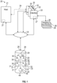
Figure 1 illustrates an exemplary planning system. -
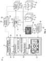
Figure 2 illustrates aspects of the exemplary planning system ofFigure 1 . -
Figure 3A illustrates an exemplary user interface of the planning system ofFigure 2 . -
Figure 3B illustrates another exemplary user interface of the planning system ofFigure 2 . -
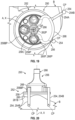
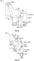
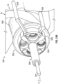
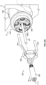
Figure 4 illustrates an exemplary orthopaedic assembly according to the invention including an implant, transfer guide and transfer members. -
Figure 5 illustrates an isolated view of the transfer guide ofFigure 4 . -
Figure 5A illustrates aspects of the transfer guide ofFigure 5 . -
Figure 6 illustrates a perspective view of portions of the transfer guide ofFigure 5 . -
Figure 7 illustrates an axial view of the transfer guide ofFigure 5 . -
Figure 8 illustrates a sectional view of portions of the assembly ofFigure 4 . -
Figure 9 illustrates a perspective view of portions of the assembly ofFigure 4 . -
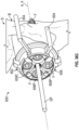
Figure 10 illustrates an axial view of the assembly ofFigure 4 positioned at a surgical site. -
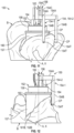
Figure 11 illustrates a side view of the assembly ofFigure 10 . -
Figure 12 illustrates another side view of the assembly ofFigure 10 . -
Figure 13A illustrates the assembly ofFigure 4 including an implant, transfer members and transfer guide positioned relative to a surgical site. -
Figure 13B illustrates a positioning object situated at the surgical site utilizing the transfer guide ofFigure 10 . -
Figure 13C illustrates the positioning object with the transfer guide ofFigure 13B removed from the surgical site. -
Figure 13D illustrates fasteners positioned relative to the implant ofFigure 13A . -
Figure 13E illustrates the implant secured with the fasteners ofFigure 13D . -
Figure 13F illustrates the positioning object ofFigure 13E removed from the implant. -
Figure 14 illustrates an exemplary method of planning and implementing an orthopaedic procedure. -
Figure 15 illustrates another exemplary orthopaedic assembly not in accordance with the invention including an implant, transfer guide and transfer members and incorporating a coupling member. -
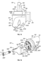
Figure 16 illustrates an exploded view of the assembly ofFigure 15 . -
Figure 17 illustrates a perspective view of a transfer guide of the assembly ofFigure 15 . -
Figure 18 illustrates another perspective view of a transfer guide of the assembly ofFigure 15 . -
Figure 19 illustrates an axial view of the assembly ofFigure 15 positioned at a surgical site. -
Figure 20 illustrates a side view of the assembly ofFigure 19 . -
Figure 21A illustrates the assembly ofFigure 15 including a transfer guide, coupling member and implant positioned relative to a surgical site. -
Figure 21B illustrates a positioning object situated at the surgical site utilizing the coupling member ofFigure 21A . -
Figure 21C illustrates the coupling member and transfer guide ofFigure 21B removed from the surgical site. -
Figure 21D illustrates fasteners positioned relative to the implant ofFigure 21C . -
Figure 21E illustrates the implant secured with the fasteners ofFigure 21D . -
Figure 21F illustrates the positioning object ofFigure 21E removed from the implant. -
Figure 22 illustrates another exemplary orthopaedic assembly not in accordance with the invention including an implant, transfer guide and transfer members that may have a patient-specific configuration and may incorporate a coupling member. -
Figure 23 illustrates an exploded view of the assembly ofFigure 22 . -
Figure 24 illustrates a perspective view of the transfer guide ofFigure 22 . -
Figure 25 illustrates another perspective view of the transfer guide ofFigure 22 . -
Figure 26 illustrates a perspective view of the transfer guide ofFigure 22 situated relative to tissue. -
Figure 27A illustrates the assembly ofFigure 22 including a transfer guide, coupling member and implant positioned relative to a surgical site. -
Figure 27B illustrates an axial view of the assembly ofFigure 27A . -
Figure 27C illustrates a positioning object situated at the surgical site utilizing the coupling member ofFigure 27A . -
Figure 27D illustrates the coupling member and transfer guide ofFigure 27C removed from the surgical site. -
Figure 27E illustrates fasteners positioned relative to the implant ofFigure 27D . -
Figure 27F illustrates the implant secured with the fasteners ofFigure 21E . -
Figure 27G the positioning object ofFigure 27F removed from the implant. -
Figure 28 illustrates another exemplary orthopaedic assembly not in accordance with the invention situated at a surgical site and including an implant, transfer guide and transfer members that may have a patient-specific configuration and may incorporate a coupling member. -
Figure 29 illustrates a side view of the implant ofFigure 28 . -
Figure 30 illustrates an axial view of the implant ofFigure 28 . -
Figure 31 illustrates another exemplary orthopaedic assembly not in accordance with the invention situated at a surgical site and including an implant, transfer guide and transfer members and that may incorporate a coupling member. -
Figure 32 illustrates a perspective view of the transfer guide ofFigure 31 . -
Figure 33A illustrates the assembly ofFigure 28 including a transfer guide, coupling member and implant positioned relative to a surgical site. -
Figure 33B illustrates a positioning object situated at the surgical site utilizing the coupling member ofFigure 33A . -
Figure 33C illustrates the coupling member and transfer guide ofFigure 33B removed from the surgical site. -
Figure 33D illustrates the implant ofFigure 33C secured with fasteners. -
Figure 34 illustrates another exemplary orthopaedic assembly not in accordance with the invention including a transfer guide that may establish a snap-fit connection. -
Figure 35 illustrates a perspective view of the transfer guide ofFigure 34 . -
Figure 36 illustrates a perspective view of the assembly ofFigure 34 at a surgical site. -
Figure 37 illustrates an axial view of the assembly ofFigure 36 . -
Figure 38A illustrates the assembly ofFigure 34 including a transfer guide, positioning member and implant positioned relative to a surgical site. -
Figure 38B illustrates fasteners and a positioning object situated at the surgical site utilizing the positioning member ofFigure 38A . -
Figure 38C illustrates the implant secured with the fasteners ofFigure 38B and the positioning member removed from the surgical site. -
Figure 38D illustrates a sectional view of the assembly, positioning object and fasteners ofFigure 38C and the positioning member ofFigure 38B . -
Figure 38E illustrates the transfer guide ofFigure 38D removed from the implant. -
Figure 39 illustrates another exemplary orthopaedic assembly not in accordance with the invention including an implant and transfer members that may be coupled to the implant by one or more breakable connections. -
Figure 40 illustrates an axial view of the assembly ofFigure 39 . -
Figure 41 illustrates a side view of the assembly ofFigure 39 . -
Figure 42 illustrates a perspective view of portions of the assembly ofFigure 39 . -
Figure 43 illustrates a plan view of a transfer member. -
Figure 44 illustrates a perspective view of the transfer member ofFigure 43 . -
Figure 45 illustrates a severed state of the breakable connections ofFigure 39 . -
Figure 46 illustrates another view of one of the severed breakable connections ofFigure 45 . -
Figure 47A illustrates a perspective view of the assembly ofFigure 39 including an implant and transfer members positioned relative to a surgical site. -
Figure 47B illustrates an axial view of the assembly ofFigure 47A . -
Figure 47C illustrates another perspective view of the assembly ofFigure 47A . -
Figure 47D illustrates a positioning object and fasteners situated relative to the assembly ofFigures 47A . -
Figure 47E illustrates the implant secured with the fasteners ofFigure 47D and tooling positioned relative to one of the transfer members. -
Figure 47F illustrates the transfer members ofFigure 47E severed from the implant utilizing the tooling. -
Figure 48 illustrates an exemplary method of forming an orthopaedic implant assembly. -
Figure 49 illustrates a printing assembly positioned relative to a substrate. -
Figure 50 illustrates a portion of an orthopaedic assembly formed by the printing assembly. -
Figure 51 illustrates a side view of the orthopaedic assembly formed by the printing assembly. -
Figure 52 illustrates another side view of the orthopaedic assembly ofFigure 51 . -
Figure 53 illustrates a sectional view of the assembly ofFigure 52 . - Like reference numbers and designations in the various drawings indicate like elements.
- This disclosure relates to surgical planning and implementation, including positioning implants relative to patient anatomy. The planning systems, assemblies and methods disclosed herein may be utilized for planning and implementing orthopaedic procedures to restore functionality to a joint. Implants may be positioned utilizing one or more transfer members.
- Transfer members may be associated with a predetermined surgical plan. One or more parameters of the surgical plan may be transferred to or by the transfer members for implementing a predetermined position of the respective implant. The surgical plan may be tailored to the individual patient, which may improve healing. The transfer members may be coupled directly to the implant or may be incorporated into a transfer guide or device, which may improve accuracy in positioning implants according to surgical plans. The disclosed techniques may reduce complexity in implementing the surgical plans, including reduced packaging and instrumentation. The transfer members may be single use and/or reusable, which may provide the surgeon flexibility in implementing the surgical plans.
- A transfer guide for an orthopaedic procedure according to the invention includes a guide body that is configured to be coupled to an implant and a plurality of transfer members that extend from the guide body. The one or more transfer members are configured to contact tissue.
- In a further implementation, the guide body may include a passage dimensioned to at least partially receive a guide pin insertable in bone.
- In a further implementation, the one or more transfer members may be positioned relative to the guide body based on a predetermined surgical plan.
- According to the invention, each of the transfer members is moveable axially relative to the guide body.
- Each of the transfer members includes a first portion extending radially outward from the guide body and a second portion extending axially from the first portion. The second portion is configured to contact tissue.
- In a further implementation, each of the transfer members may include a third portion that extends from the first portion. The third portion may be translatable along a respective slot established in the periphery of the guide body to set a position of the terminal end portion relative to the guide body.
- In a further implementation, the first portion and the second portion may establish a substantially L-shaped geometry.
- In a further implementation that does not form part of the present invention, the one or more transfer members may be integrally formed with the guide body.
- An orthopaedic implant according to an exemplary aspect of this disclosure may include a baseplate and an augment that may extend outwardly from the baseplate. The augment may be dimensioned to contact bone. The implant may include one or more transfer members that may extend from the augment. The one or more transfer members may be configured to contact bone. Each of the one or more transfer members may be coupled to the augment at a respective breakable connection.
- In a further implementation, the one or more transfer members may be dimensioned based on a predetermined surgical plan.
- In a further implementation, the one or more transfer members may be integrally formed with the augment.
- In a further implementation, the augment may be formed along the baseplate.
- In a further implementation, the breakable connection may be configured to sever in response to a predetermined quantity of torque at an interface.
- In a further implementation, the breakable connection may be configured to sever in response to the predetermined quantity of torque in a first rotational direction with respect to an axis extending through the interface, but not a second rotational direction opposed to the first rotational direction.
- In a further implementation, the one or more transfer members may include a plurality of transfer members circumferentially distributed about a periphery of the augment.
- In a further implementation, each of the transfer members may include a first portion extending radially outward from the periphery of the augment and a second portion extending axially from the first portion. The terminal end portion may be configured to contact tissue.
- In a further implementation, the breakable connection may be configured to sever in response to a predetermined quantity of torque in a first rotational direction with respect to an axis extending through the second portion, but not a second rotational direction opposed to the first rotational direction.
- In a further implementation, the baseplate may include a central aperture and a plurality of peripheral apertures circumferentially distributed about the central aperture. Each of the peripheral apertures may be aligned with a respective passage through the augment. Each of the peripheral apertures may be dimensioned to receive a respective fastener partially receivable through the respective passage and into bone.
- In a further implementation, the central aperture may be dimensioned to receive a guide pin insertable into bone to set a position of the implant.
- An assembly for an orthopaedic procedure according to the present invention includes an implant that is configured to abut bone and a transfer guide. The transfer guide includes a guide body configured to be coupled to the implant and a plurality of transfer members extending from the guide body. Each of the transfer members is configured to contact bone.
- In a further implementation, the guide body may include a passage dimensioned to at least partially receive a guide pin insertable in bone to set a position of the implant.
- In a further implementation, the one or more transfer members may be positioned relative to the guide body based on a predetermined surgical plan.
- In a further implementation, the implant may include a baseplate and an augment that may extend from the baseplate relative to an axis. The augment may be dimensioned to contact bone.
- In a further implementation, the one or more transfer members may be dimensioned to be at least partially axially aligned with the augment relative to the axis.
- In a further implementation, the augment may include an augment body extending between a first face and a second face. The first face may extend along the baseplate. The second face may be dimensioned to substantially follow a contour of the bone.
- In a further implementation, the guide body may include first threads that may mate with second threads along the baseplate to mechanically attach the transfer guide to the implant.
- In a further implementation, the baseplate may include a central aperture and a plurality of peripheral apertures circumferentially distributed about the central aperture. Each of the peripheral apertures may be dimensioned to receive a respective fastener to secure the implant to bone. The transfer guide may include an alignment member. The alignment member may be dimensioned to be insertable into an aperture along the baseplate to limit relative rotation between the transfer guide and the implant.
- In a further implementation, the guide body may include a passage configured to be aligned with the central aperture in an installed position. The passage may be dimensioned to at least partially receive a guide pin insertable through the central aperture and into bone to set a position of the implant.
- According to the invention, each of the transfer members is moveable axially between a first position and a second position.
- According to the invention, each of the transfer members includes a first portion extending radially outward from the guide body and a second portion extending axially from the first portion. The second portion is configured to abut tissue adjacent the implant.
- In a further implementation, the implant may include a baseplate and an augment that may extend from the baseplate relative to an axis. The augment may be dimensioned to contact bone. The baseplate may include a central aperture and a plurality of peripheral apertures circumferentially distributed about the central aperture. Each of the peripheral apertures may be dimensioned to receive a respective fastener to secure the implant to bone. The guide body may include a coupling feature at least partially receivable in the central aperture to secure the transfer guide to the implant. The transfer guide may include an alignment member that may be dimensioned to be insertable into an aperture in the baseplate to limit relative rotation between the transfer guide and the implant.
- In a further implementation, the coupling feature may include first threads that may mate with second threads along the central aperture to mechanically attach the transfer guide to the implant.
- In a further implementation, the one or more transfer members may be integrally formed with the guide body.
- In a further implementation, the guide body may include a passage dimensioned to receive a coupling member. The coupling member may be insertable into the passage and the central aperture to mechanically attach the transfer guide to the implant.
- In a further implementation, the coupling member may include a passage. The passage may be dimensioned to receive a guide pin insertable through the central aperture and into bone to set a position of the implant.
- In a further implementation, the implant may include a baseplate and an augment that may extend outwardly from the baseplate. The augment may be dimensioned to contact bone. The transfer guide may include an abutment member that may extend outwardly from the guide body. The abutment member may be dimensioned to at least partially follow a periphery of the baseplate.
- In a further implementation, each of the one or more transfer members may extend from the guide body to a terminal end portion. The one or more transfer members may include a first transfer member and a second transfer member. The terminal end portion of the first transfer member may have has a geometry that may differ from a geometry of the terminal end portion of the second transfer member.
- In a further implementation, each terminal end portion may be dimensioned with respect to a predetermined surface contour of the bone.
- In a further implementation, the one or more transfer members may include a transfer body and a transfer arm that may interconnect the guide body and the transfer body. The transfer body may include a contact surface that may be dimensioned with respect to a predetermined surface contour of the bone.
- In a further implementation, the implant may include a baseplate and an augment that may extend outwardly from the baseplate. The augment may be dimensioned to contact bone. The guide body may be dimensioned to follow a periphery of the baseplate.
- In a further implementation that does not form part of the invention, the one or more transfer members may be integrally formed with the guide body.
- In a further implementation, the transfer guide may include a plurality of fixation members that may be dimensioned to interface with a circumferential rim of the baseplate to establish a snap-fit connection.
- In a further implementation, the baseplate may include a central aperture and a plurality of peripheral apertures circumferentially distributed about the central aperture. Each of the peripheral apertures may be dimensioned to receive a respective fastener to secure the implant to bone. The transfer guide may include one or more alignment members that may extend inwardly from the guide body. Each of the one or more alignment members may be dimensioned to be insertable into a respective one of the peripheral apertures to limit relative rotation between the transfer guide and the implant.
- In a further implementation, the central aperture may be dimensioned to receive a coupling member. The coupling member may include a passage. The passage may be dimensioned to receive a guide pin insertable through the central aperture and into bone to set a position of the implant.
- In a further implementation, the coupling member may be spaced apart from the transfer members in an installed position.
- In a further implementation, the guide body may be dimensioned to encircle and at least partially receive the periphery of the baseplate.
- A method of installing an orthopaedic implant may include positioning one or more transfer members to contact bone. The one or more transfer members may be coupled to an implant. The method may include positioning the implant relative to the bone based on the positioning of the one or more transfer members.
- In a further implementation, the implant may include a baseplate and an augment that may extend outwardly from the baseplate. The step of positioning the implant may occurs such that a surface of the augment may contact the bone.
- In a further implementation, the surface of the augment may be dimensioned to substantially follow a surface contour of the bone based on a predetermined surgical plan.
- In a further implementation, the baseplate may include a central aperture and a plurality of peripheral apertures circumferentially distributed about the central aperture. Each of the peripheral apertures may be aligned with a respective passage through the augment. The method may include positioning a respective fastener in each respective peripheral aperture and then into the bone to secure the implant.
- In a further implementation, the method may include inserting one or more alignment members in a respective one of the peripheral apertures to limit relative rotation between the one or more transfer members and the baseplate.
- In a further implementation, the method may include establishing a surgical plan. The surgical plan may be based on a surface profile of the bone. The surgical plan may include at least one dimension that may be associated with the one or more transfer members relative to the surface profile.
- In a further implementation, each of the one or more transfer members may include a respective contact surface. The method may include forming the contact surface to substantially follow the surface profile of the bone based on the surgical plan.
- In a further implementation, the method may include coupling a transfer guide to the implant. The transfer guide may include a guide body that may interface with the implant. The one or more transfer members may extend from the guide body.
- In a further implementation, the method may include the step of positioning one or more transfer members may include moving the one or more transfer members between a first position and a second position relative to the guide body based on the at least dimension.
- In a further implementation, the guide body may include a passage. The method may include positioning a guide pin through the passage in the guide body, then through the implant, and then into the bone.
- In a further implementation, the method may include integrally forming the one or more transfer members with the guide body based on the at least one dimension subsequent to the step of establishing the surgical plan.
- In a further implementation, the transfer guide may include a plurality of fixation members. The step of coupling the transfer guide to the implant may include positioning the plurality of fixation members relative to the implant to establish a snap-fit connection.
- In a further implementation, the method may include integrally forming the one or more transfer members with the implant.
- In a further implementation, each of the one or more transfer members may be coupled to the implant at a respective breakable connection. The method may include severing the breakable connection in response to a predetermined quantity of force applied to the respective transfer member.
- In a further implementation, the bone may be a portion of a glenoid.
-
Figure 1 illustrates anexemplary planning system 20 that may be utilized for planning surgical procedures. Thesystem 20 may be used for planning orthopaedic procedures, including pre-operatively, intra-operatively and/or post-operatively to create, edit, execute and/or review surgical plans. Thesystem 20 may be utilized for various orthopaedic and other surgical procedures, such as an arthroplasty to repair a joint. Thesystem 20 may be utilized in the placement of an implant, such as an implant incorporated into a shoulder prosthesis, for example. Although the planning systems and methods disclosed herein primarily refer to repair of a glenoid or humerus during an anatomic or reverse shoulder reconstruction, it should be understood that theplanning system 20 may be utilized in the repair of other locations of the patient and other surgical procedures including repair of other bones and joints such as a wrist, hand, hip, knee or ankle and repair of fractures and other deformities. - The
system 20 may include ahost computer 21 and one ormore client computers 22. Thehost computer 21 may be configured to execute one or more software programs. In some implementations, thehost computer 21 may be more than one computer jointly configured to process software instructions serially or in parallel. - The
host computer 21 may be in communication with one or more networks such as anetwork 23 comprised of one or more computing devices. Thenetwork 23 may be a private local area network (LAN), a private wide area network (WAN), the Internet, or a mesh network, for example. - The
host computer 21 and eachclient computer 22 may include one or more of a computer processor, memory, storage means, network device and input and/or output devices and/or interfaces. The input devices may include a keyboard, mouse, etc. The output device may include a monitor, speakers, printers, etc. The memory may, for example, include UVPROM, EEPROM, FLASH, RAM, ROM, DVD, CD, a hard drive, or other computer readable medium which may store data and/or other information relating to the planning and implementation techniques disclosed herein. Thehost computer 21 and eachclient computer 22 may be a desktop computer, laptop computer, smart phone, tablet, or any other computing device. The interface may facilitate communication with the other systems and/or components of thenetwork 23. - Each
client computer 22 may be configured to communicate with thehost computer 21 directly via adirect client interface 24 or over thenetwork 23. In another implementation, theclient computers 22 are configured to communicate with each other directly via a peer-to-peer interface 25. - The
system 20 may include, or may be coupled to, one ormore imaging devices 26. Eachclient computer 22 may be coupled to one ormore imaging devices 26, for example. Eachimaging device 26 may be configured to capture or acquire one ormore images 30 of patient anatomy residing within a scan field (e.g., window) of theimaging device 26. Theimaging device 26 may be configured to capture or acquire two dimensional (2D) and/or three dimensional (3D) greyscale and/orcolor images 30.Various imaging devices 26 may be utilized, such as an X-ray machine, computerized tomography (CT) machine or magnetic resonance imaging (MRI) machine that obtains one or more images of a patient. - The
client computers 22 may be configured to execute one or more software programs, such as a various surgical tools. Eachclient computer 22 may be operable to access and locally and/or remotely execute aplanning environment 27. Theplanning environment 27 may be a standalone software package or may be incorporated into another surgical tool. Theplanning environment 27 may be configured to communicate with thehost computer 21 either over thenetwork 23 or directly through thedirect client interface 24. - The
planning environment 27 may be configured to interact with one or more of theimaging devices 26 to capture or acquireimages 30 of patient anatomy. Theplanning environment 27 may provide a display or visualization of one ormore images 30,bone models 31,implant models 32 and/ortransfer models 48 via one or more graphical user interfaces (GUI). Eachimage 30,bone model 31,implant model 32,transfer model 48 and other data and information may be stored in one or more files or records according to a specified data structure. - The
system 20 may include at least onestorage system 28, which may be operable to store or otherwise provide data to other computing devices. Thestorage system 28 may be a storage area network device (SAN) configured to communicate with thehost computer 21 and/or theclient computers 22 over thenetwork 23, for example. In implementations, thestorage system 28 may be incorporated within or directly coupled to thehost computer 21 and/orclient computers 22. Thestorage system 28 may be configured to store one or more of computer software instructions, data, database files, configuration information, etc. - In some implementations, the
system 20 may be a client-server architecture configured to execute computer software on thehost computer 21, which may be accessible by theclient computers 22 using either a thin client application or a web browser executing on theclient computers 22. Thehost computer 21 may load the computer software instructions from local storage, or from thestorage system 28, into memory and may execute the computer software using the one or more computer processors. - The
system 20 may include one ormore databases 29. Thedatabases 29 may be stored at a central location, such as thestorage system 28. In another implementation, one ormore databases 29 may be stored at thehost computer 21 and/or may be a distributed database provided by one or more of theclient computers 22. Eachdatabase 29 may be a relational database configured to associate one ormore images 30,bone models 31,implant models 32 and/ortransfer models 48 to each other and/or asurgical plan 33. Eachsurgical plan 33 may be associated with the anatomy of a respective patient. Eachimage 30,bone model 31,implant model 32,transfer model 48 andsurgical plan 33 may be assigned a unique identifier or database entry. Thedatabase 29 may be configured to store data and other information corresponding to theimages 30,bone models 31,implant models 32,transfer models 48 andsurgical plans 33 in one or more database records or entries, and/or may be configured to link or otherwise associate one or more files corresponding to eachrespective image 30,bone model 31,implant model 32,transfer model 48 andsurgical plan 33.Images 30,bone models 31,implant models 32,transfer models 48 and associatedsurgical plans 33 stored in the database(s) 29 may correspond to respective patient anatomies from prior surgical cases, and may be arranged into one or more predefined categories such as sex, age, ethnicity, defect category, procedure type, surgeon, facility or organization, etc. - Each
image 30 andbone model 31 may include data and other information obtained from one or more medical devices or tools, such as theimaging devices 26. Thebone model 31 may include coordinate information relating to an anatomy of the patient obtained or derived from image(s) 30 captured or otherwise obtained by the imaging device(s) 26. Eachimplant model 32,transfer model 48 may include coordinate information associated with a predefined design or a design established or modified by theplanning environment 27. Theplanning environment 27 may incorporate and/or interface with one or more modeling packages, such as a computer aided design (CAD) package, to render themodels images 30 in a display screen of a GUI. - The
implant models 32 may correspond to implants and components of various shapes and sizes. Each implant may include one or more components that may be situated at a surgical site including screws, anchors and/or grafts. Eachimplant model 32 may correspond to a single component or may include two or more components that may be configured to establish an assembly. Each implant and associated component(s) may be formed of various materials, including metallic and/or non-metallic materials. Eachbone model 31,implant model 32 andtransfer model 48 may correspond to 2D and/or 3D geometry, and may be utilized to generate a wireframe, mesh and/or solid construct in a display. - Each
surgical plan 33 may be associated with one or more of theimages 30,bone models 31,implant models 32 and/ortransfer models 48. Thesurgical plan 33 may include various parameters associated with theimages 30,bone models 31,implant models 32 and/ortransfer models 48. For example, thesurgical plan 33 may include parameters relating to bone density and bone quality associated with patient anatomy captured in the image(s) 30. Thesurgical plan 33 may include parameters including spatial information relating to relative positioning and coordinate information of the selected bone model(s) 30, implant model(s) 32 and/or transfer model(s) 48. - The
surgical plan 33 may include one or more revisions to abone model 31 and information relating to a position of animplant model 32 and/ortransfer model 48 relative to the original and/or revisedbone model 31. Thesurgical plan 33 may include coordinate information relating to the revisedbone model 31 and a relative position of theimplant model 32 and/ortransfer model 48 in predefined data structure(s). Theplanning environment 27 may be configured to make one or more revisions to atransfer model 48 automatically or in response to user interaction with the user interface. Revisions to eachbone model 31,implant model 32,transfer model 48 and/orsurgical plan 33 may be stored in thedatabase 29 automatically and/or in response to user interaction with thesystem 20. - One or more surgeons and other users may be provided with a
planning environment 27 via theclient computers 22 and may simultaneously access eachimage 30,bone model 31,implant model 32,transfer model 48 andsurgical plan 33 stored in the database(s) 29. Each user may interact with theplanning environment 27 to create, view and/or modify various aspects of thesurgical plan 33. Eachclient computer 22 may be configured to store local instances of theimages 30,bone models 31,implant models 32,transfer models 48 and/orsurgical plans 33, which may be synchronized in real-time or periodically with the database(s) 29. Theplanning environment 27 may be a standalone software package executed on aclient computer 22 or may be provided as one or more services executed on thehost computer 21, for example. - Referring to
Figure 2 , with continuing reference toFigure 1 , thesystem 20 may include acomputing device 34 including at least oneprocessor 35 coupled tomemory 36. Thecomputing device 34 may include any of the computing devices disclosed herein, including thehost computer 21 and/orclient computer 22. Theprocessor 35 may be configured to execute aplanning environment 27 for creating, editing, executing and/or reviewing one or moresurgical plans 33 and any associatedbone models 31,implant models 32 andtransfer models 48 during pre-operative, intraoperative and/or post-operative phases of a surgery. - The
planning environment 27 may include at least adata module 37, adisplay module 38, aspatial module 39 and acomparison module 40. Although four modules are shown, it should be understood that fewer or more than four modules may be utilized and/or one or more of the modules may be combined to provide the disclosed functionality. - The
data module 37 may be configured to access, retrieve and/or store data and other information in the database(s) 29 corresponding to one ormore images 30 of patient anatomy, bone model(s) 31, implant model(s) 32, transfer model(s) 48 and/or surgical plan(s) 33. The data and other information may be stored in one ormore databases 29 as one or more records orentries 41. In some implementations, the data and other information may be stored in one or more files that are accessible by referencing one or more objects or memory locations referenced by therecords 41. - The
memory 36 may be configured to access, load, edit and/or store instances of one ormore images 30,bone models 31,implant models 32,transfer models 48 and/orsurgical plans 33 in response to one or more commands from thedata module 37. Thedata module 37 may be configured to cause thememory 36 to store a local instance of the image(s) 30, bone model(s) 31, implant model(s) 32, transfer model(s) 48 and/or surgical plan(s) 33, which may be synchronized with therecords 41 in the database(s) 29. - The
data module 37 may be configured to receive data and other information corresponding to at least one ormore images 30 of patient anatomy from various sources such as the imaging device(s) 26. Thedata module 37 may be configured to command theimaging device 26 to capture or acquire theimages 30 automatically or in response to user interaction. - The
display module 38 may be configured to display data and other information relating to one or moresurgical plans 33 in at least one graphical user interface (GUI) 43, including one or more of theimages 30,bone models 31,implant models 32 and/ortransfer models 48. Thecomputing device 34 may incorporate or be coupled to adisplay device 42. Thedisplay module 38 may be configured to cause thedisplay device 42 to display information in theuser interface 43. A surgeon or other user may interact with theuser interface 43 via theplanning environment 27 to view one ormore images 30 ofpatient anatomy 46 and/or any associatedbone models 31,implant models 32 andtransfer models 48. The surgeon or other user may interact with theuser interface 43 via theplanning environment 27 to create, edit, execute and/or review one or moresurgical plans 33. - Referring to
Figure 3A-3B , with continuing reference toFigure 2 , theuser interface 43 may include one ormore display windows 44 and one or more objects 45. Thedisplay windows 44 may include first, second and third display windows 44-1, 44-2, 44-3, as illustrated inFigure 3A , and may include fourth and fifth display windows 44-4, 44-5 as illustrated inFigure 3B . Although fivedisplay windows 44 are shown, it should be understood that fewer or more than fivedisplay windows 44 may be utilized in accordance with the teachings disclosed herein. - A surgeon or user may interact with the
user interface 43 including theobjects 45 and/ordisplay windows 44 to retrieve, view, edit, store, etc., various aspects of asurgical plan 33, such as the selected image(s) 30, bone model(s) 31, implant model(s) 32 and/or transfer model(s) 48. Theobjects 45 may include graphics such as menus, tabs and buttons accessible by user interaction, such astabs 45T,buttons 45B, drop-downlists 45L, anddirectional indicator 45D. Theobjects 45 may be organized in one ormore menu items 45M associated with therespective display windows 44. Geometric objects, including selected image(s) 30, bone model(s) 31, implant model(s) 32, transfer model(s) 48 and/or other information relating to thesurgical plan 33, may be displayed in one or more of thedisplay windows 44 as illustrated inFigures 3A-3B . Eachtransfer model 48 may include one ormore transfer members 54, which may be associated with atransfer guide 56 as illustrated in windows 44-4, 44-5. - The surgeon may interact with the
objects 45 to specify various aspects of asurgical plan 33. For example, the surgeon may select one of thetabs 45T to view or specify aspects of thesurgical plan 33 for one portion of a joint, such as a glenoid (see, e.g.,Figure 3B ), and may select another one of thetabs 45T to view or specify aspects of thesurgical plan 33 for another portion of the joint, such as a humerus (see, e.g.,Figure 3A ). - The surgeon may interact with the
menu items 45M to select and specify various aspects of thebone models 31,implant models 32 and/ortransfer models 48 from thedatabase 29. For example, thedisplay module 38 may be configured to display one ormore bone models 31 together with the respective image(s) 30 of thepatient anatomy 46 andimplant models 32 selected in response to user interaction with theuser interface 43, as illustrated inFigure 3A . The user may interact with the drop-downlists 45L associated with the first display window 44-1 to specify implant type, resection angle and implant size. The resection angle menu item may be associated with a resection plane R1 (shown in dashed lines in window 44-1 for illustrative purposes). - The user may interact with
buttons 45B to change (e.g., increase or decrease) the resection angle. The user may interact withbuttons 45B adjacent the selectedimplant model 32 to change (e.g., increase or decrease) a size of a component of the selectedimplant model 32. Thebuttons 45B may be overlaid onto or may be situated adjacent to thedisplay windows 44. The user may interact with thedirectional indicator 45D to move a portion of the selectedimplant model 32 in different directions (e.g., up, down, left, right) in the second display window 44-2. The surgeon may drag or otherwise move the selectedimplant model 32 to a desired position in the second display window 44-2 utilizing a mouse, for example. The surgeon may interact with one of the drop-downlists 45L to specify a type and/or size of a component of the selectedimplant model 32. - The
display module 38 may be configured to superimpose one or more of thebone models 31, andimplant models 32 over one or more of theimages 30, as illustrated by window 44-1. Theimplant model 32 may include one or more components that establish an assembly. At least a portion of theimplant model 32 may be configured to be at least partially received in a volume of a selected one of thebone models 31. Theimplant model 32 may have an articulation surface dimensioned to mate with an articular surface of an opposed bone or implant. - The
display windows 44 may be configured to display theimages 30,bone models 31,implant models 32 and/or transfer model(s) 48 at various orientations. Thedisplay module 38 may be configured to display two dimensional (2D) representation(s) of the selected bone model(s) 31, implant model(s) 32 and/or transfer model(s) 48 in the first and/or second display windows 44-1, 44-2, and may be configured to display 3D representation(s) of the selectedbone model 31,implant model 32 and/or transfer model(s) 48 in the third display window 44-3, for example. The surgeon may interact with theuser interface 43 to move the selectedbone model 31, selectedimplant model 32 and/or selectedtransfer model 48 in 2D space (e.g., up, down, left, right) and/or 3D space. In other implementations, thedisplay module 38 may be configured to display a 2D representation of the selected bone model(s) 31, selected implant model(s) 32 in the third display window 44-3. - The
display module 38 may be configured such that the selected image(s) 30, bone model(s) 31, implant model(s) 32 and/or transfer model(s) 48 may be selectively displayed and hidden (e.g., toggled) in one or more of thedisplay windows 44 in response to user interaction with theuser interface 43, which may provide the surgeon with enhanced flexibility in reviewing aspects of thesurgical plan 33. For example, the surgeon may interact with the drop-downlists 45L to selectively display and hide components of the selectedimplant model 32 in the third display window 44-3. - The selected
bone model 31 may correspond to a bone associated with a joint, including any of the exemplary joints disclosed herein, such as a humerus as illustrated inFigure 3A . Thedisplay module 38 may be configured to display a sectional view of the selectedbone model 31 and selectedimplant model 32 in the first viewing window 44-1, for example. The sectional view of the bone model(s) 31 may be presented or displayed together with the associated image(s) 30 of thepatient anatomy 46. - The
spatial module 39 may be configured to establish the resection plane R1 along the selectedbone model 31. A volume of the selectedimplant model 32 may be at least partially received in a volume of the selectedbone model 31 along the resection plane R1. The resection plane R1 may be defined by a resection angle. - The
spatial module 39 may be configured to cause thedisplay module 38 to display an excised portion of the selectedbone model 31 to be displayed in the first display window 44-1 in a different manner than a remainder of thebone model 31 on an opposed side of the resection plane R1. For example, the excised portion of thebone model 31 may be hidden from display in the first display window 44-1 such that the respective portion of theimage 30 of thepatient anatomy 46 is shown, as illustrated inFigure 3A . In other implementations, the excised portion of the selectedbone model 31 may be displayed in a relatively darker shade. Thespatial module 39 may determine the excised portion by comparing coordinates of thebone model 31 with respect to a position of the resection plane R1, for example. The user may interact with one ormore buttons 45B to toggle between a volume of previous and revised (e.g., resected) states of the selectedbone model 31. - The
planning environment 27 may be configured such that changes in one of thedisplay windows 44 are synchronized with each of theother windows 44. The changes may be synchronized between thedisplay windows 44 automatically and/or manually in response to user interaction. - The surgeon may utilize various instrumentation and devices to implement each
surgical plan 33, including preparing the surgical site and securing one or more implants to bone or other tissue to restore functionality to the respective joint. Each of thetransfer models 48 may be associated with a respective instrument or device (e.g., transfer guide) or arespective implant model 32. - The
surgical plan 33 may be associated with one or more positioning objects such as a guide pin (e.g., guide wire or Kirschner wire) dimensioned to be secured in tissue to position and orient the various instrumentation, devices and/or implants. Thedisplay module 38 may be configured to display a virtual position VP and virtual axis VA in one or more of thedisplay windows 44. The virtual position VP may be associated with a specified position of the positioning object relative to thepatient anatomy 46. The virtual axis VA may extend through the virtual position VP and may be associated with a specified orientation of the positioning object relative to thepatient anatomy 46. Thespatial module 39 may be configured to set the virtual position VP and/or virtual axis VA in response to placement of arespective implant model 32 relative to thebone model 31 and associatedpatient anatomy 46. The virtual position VP and/or virtual axis VA may be set and/or adjusted automatically based on a position and orientation of the selectedimplant model 32 relative to the selectedbone model 31 and/or in response to user interaction with theuser interface 43. - The
spatial module 39 may be configured to determine one or more contact points CP associated with thepatient anatomy 46. The contact points CP may be associated with one or more landmarks or other surface features along thebone model 31 and/or other portions of thepatient anatomy 46. Each contact point CP may be established along an articular surface or non-articular surface of a joint. Thespatial module 39 may be configured to set the contact points CP based on the virtual position VP, virtual axis VA and/or position and orientation of therespective implant model 32 relative to thepatient anatomy 46. Thespatial module 39 may be configured to cause thedisplay module 38 to display the contact points CP in one or more of thedisplay windows 44, as illustrated inFigures 3A-3B . In implementations, the contact points CP may be set and/or adjusted automatically based on a position of theimplant model 32 and/or in response to user interaction with theuser interface 43. The virtual position VP, virtual axis VA and/or contact points CP may be stored in one ormore records 41 in thedatabase 29 and may be associated with the respectivesurgical plan 33. - The
comparison module 40 may be configured to generate or set one or more parameters associated with implementing thesurgical plan 33. The parameters may include one or more settings or dimensions associated with therespective transfer models 48. The parameters may be based on the virtual position VP, virtual axis VA and/or contact points CP. Thecomparison module 40 may be configured to determine one or more settings or dimensions associated with therespective transfer models 48 relative to thepatient anatomy 46, bone model(s) 31, implant model(s) 46, virtual position VP, virtual axis VA and/or contact points CP. The dimensions and settings may be utilized to form a physical instance of eachrespective transfer model 48. The settings may be utilized to specify a position and orientation of eachrespective transfer model 48 relative to theimplant model 32 and/orbone model 31. The settings may be utilized to configure one or more transfer members (e.g., objects) and related instrumentation or devices associated with thetransfer model 48. Thecomparison module 40 may be configured to generate the settings and/or dimensions such that thetransfer model 48 contacts one or more predetermined positions at or along thebone model 31 orpatient anatomy 46 in an installed position when coupled to therespective implant model 32. The predetermined positions may include one or more of the contact points CP. The settings and dimensions may be communicated utilizing various techniques, including one or more graphics in theuser interface 43 or output files. The settings and/or dimensions may be stored in one ormore records 41 in thedatabase 29 associated with thetransfer models 48. - The user may interact with a
list 45L associated with the display window 44-4 to select atransfer model 48 from thedatabase 29. Thedisplay model 38 may be configured to display the selectedtransfer model 48 in the windows 44-4 and/or 44-5 at various positions and orientations. Thespatial module 39 may be configured to set an initial position of the selectedtransfer model 48 according to the virtual position VP, virtual axis VA and/or contact points CP. - The user may interact with the
user interface 43 to set or adjust a position and/or orientation of the selectedtransfer model 48. The user may interact with directional indicators 45DT to move the selectedtransfer model 48 and/or virtual position VP in different directions (e.g., up, down, left, right) in the display windows 44-4, 45. The surgeon may drag or otherwise move the selectedtransfer model 48 and/or virtual position VP to a desired position in the windows 44-4, 44-5 utilizing a mouse, for example. The user may interact withrotational indicators 45R to adjust a position and/or orientation of thetransfer model 48 about the virtual axis VA relative to the selectedbone model 31 and/orimplant model 32. The user may interact with tilt indicators 45TT to adjust an orientation of the selectedtransfer model 48 and associated virtual axis VA at the virtual position VP relative to the selectedbone model 31 and/orimplant model 32. The user may interact with an articulation button 45BA and/or directional indicator DA (e.g., window 44-4) to cause thetransfer members 54 to articulate or otherwise move to relative to aguide body 62 of thetransfer guide 56. Thetransfer members 54 may be articulated or otherwise moved independently or synchronously, which may occur manually in response to user interaction and/or automatically in response to situating thetransfer members 54 relative to thebone model 31 and/orimplant model 32. Articulation or movement of thetransfer members 54 may occur such that thearticulation members 54 contact a surface of thebone model 31. Movement of thetransfer members 54 may cause an adjustment to the respective contact points CP. In some implementations, a position of thetransfer members 54 is fixed relative to thetransfer guide 56 and/or implant 52. - Various transfer members may be utilized with the
planning environment 27 to implement the surgical plan(s) 33, including any of the transfer members disclosed herein. Each transfer member may be associated with arespective transfer model 48. The disclosed transfer members may be incorporated into transfer guides, implants and/or assemblies to set a position and orientation of the respective implant prior to fixing or otherwise securing the implant at a surgical site. -
Figure 4 illustrates anexemplary assembly 150 for an orthopaedic procedure. Theassembly 150 may be utilized to restore functionality to shoulders and other joints, such as the repair of a glenoid or humerus during an anatomic or reverse shoulder reconstruction. Theassembly 150 may be utilized in the repair of other locations of the patient and other surgical procedures including repair of other joints such as a wrist, hand, hip, knee or ankle and repair of fractures and other deformities. In this disclosure, like reference numerals designate like elements where appropriate and reference numerals with the addition of one-hundred or multiples thereof designate modified elements that are understood to incorporate the same features and benefits of the corresponding original elements. - The
assembly 150 includes anorthopaedic implant 152 and one or more transfer members (e.g., objects) 154. Theimplant 152 and eachtransfer member 154 are configured to abut or contact bone B or other tissue (see, e.g.,Figures 10-12 ). Theassembly 150 includes atransfer guide 156 configured to interface with theimplant 152. Thetransfer guide 156 incorporates a plurality oftransfer members 154 as illustrated inFigures 4-7 . Although twotransfer members 154 are shown, it should be understood that more than twotransfer members 154 may be utilized in accordance with the invention. - A surgeon or user may position and orient the
implant 152 based on a position of thetransfer members 154 and/ortransfer guide 156 relative to tissue such as bone B (see, e.g.,Figures 10-12 ). The bone B may be a portion of a glenoid or another bone associated with a joint of a patient. - Each
transfer member 154 may be associated with a respective transfer model 48 (Figure 2 ). Thetransfer model 48 may be associated with eachtransfer member 154 of therespective transfer guide 156 and/orimplant 152. Theimplant 152 may be associated with a respective implant model 32 (Figure 2 ). The bone B may be associated with a respective bone model 31 (Figure 2 ). - The
implant 152 may include amain body 157 dimensioned to abut against bone B at a surgical site S (see, e.g.,Figures 8 and11-12 ). Themain body 157 may be dimensioned to receive one or more fasteners F (see, e.g.,Figures 13D-13E ). Each of the fasteners F may be dimensioned to be at least partially received in the bone B to secure theimplant 152 at the surgical site S. Various fasteners F may be utilized with theimplant 152, such as nails and compression screws. - The
implant 152 may include abaseplate 158 and augment 160 that establish themain body 157. Thebaseplate 158 and augment 160 may be integrally formed to establish a monolithic or unitary component or may be separate and distinct components that are fixedly attached or otherwise secured to one another. The augment 160 may be formed along thebaseplate 158 utilizing various techniques, such as printing the augment 160 on thebaseplate 158 utilizing a printing device. - Referring to
Figure 8 , with continuing reference toFigures 4-7 , thebaseplate 158 may include aplate body 159 extending along a longitudinal (e.g., central) axis X between a first (e.g., front) face 159A and a second (e.g., rear) face 159B generally opposed to thefirst face 159A. A perimeter of theplate body 159 may have a substantially circular or elliptical geometry. A substantially circular geometry may reduce a reaming width and complexity of preparing a surgical site to accept theimplant 152. - The
baseplate 158 may include acentral aperture 158C and a plurality ofperipheral apertures 158P. Theperipheral apertures 158P may be circumferentially distributed about thecentral aperture 158C relative to the longitudinal axis X (see, e.g.,Figures 13C-13F ). - The augment 160 may extend outwardly from the
baseplate 158 relative to the axis X. A perimeter of the augment 160 shown in dashed lines inFigure 8 for illustrative purposes. The augment 160 may include an augmentbody 161 dimensioned to contact bone B. The augmentbody 161 may extend along the longitudinal axis X between a first (e.g., front) face 161A and a second (e.g., rear) face 161B generally opposed to thefirst face 161A. The front faces 159A, 161A may generally correspond to a lateral side of a patient, and the rear faces 159B, 161B may generally correspond to a medial side of the patient when implanted in a surgical site. Thefront face 161A of the augment 160 may extend along therear face 159B of thebaseplate 158. - The augment
body 161 may extend outwardly from therear face 159B of thebaseplate 158 to establish anexternal surface 152E of theimplant 152. Therear face 161B and/or other portions of the augment 160 establishing theexternal surface 152E of theimplant 152 may be dimensioned to approximate a geometry of a bone defect or may have one or more surfaces having a patient-specific geometry dimensioned to substantially conform or follow a surface contour of the bone associated with a respective patient, such as a surface contour established along an articular surface of the respective bone. Therear face 159B may be dimensioned to substantially follow a surface contour of the bone B, as illustrated inFigures 8 and12 . - The augment 160 may establish one or
more passages 160P through the augmentbody 161. The augment 160 may include one or moretubular members 160T extending between therear face 159B of thebaseplate 158 and anexternal surface 152E of theimplant 152 established by the augment 160. Eachtubular member 160T may establish a respective one of thepassages 160P. Portions of the augmentbody 161 surrounding thetubular members 160T may be substantially solid or may be porous. Each of theperipheral apertures 158P andcentral aperture 158C may be aligned with a respective one of thepassages 160P. Thecentral aperture 158C and/or each of theperipheral apertures 158P may be dimensioned to receive a respective fastener F to secure theimplant 152 to bone B along the surgical site (seeFigure 13F ). - Referring to
Figures 6-7 and9-12 , with continuing reference toFigures 5 and8 , thetransfer guide 156 includes aguide body 162 configured to be coupled to theimplant 152, as illustrated inFigures 9-12 . Thetransfer guide 156 includes a plurality oftransfer members 154 extending from theguide body 162. Thetransfer members 154 may be positioned relative to theguide body 162 based on a predetermined surgical plan. The predetermined surgical plan may be established by theplanning system 20 and utilizing any of the techniques disclosed herein. - The
guide body 162 may include apassage 162P extending along a longitudinal (e.g., central) axis A of thetransfer guide 156, as illustrated inFigures 7 and10 . Thepassage 162P may be configured to be aligned with the central aperture 162C in an installed position (see, e.g.,Figures 13A-13B ). - The
transfer guide 156 may be utilized to set a position and/or orientation of one or more positioning objects such as a guide pin GP, as illustrated inFigures 13A-13B . Thecentral aperture 158C andrespective passage 162P may be dimensioned to at least partially receive the guide pin GP to set the position and/or orientation of the guide pin GP, as illustrated inFigure 13C . The guide pin GP may be insertable through thecentral aperture 158C, then through thepassage 160P and then into bone B to set a position and/or orientation of theimplant 152 relative to the longitudinal axis A of thetransfer guide 156. The guide pin GP is illustrated in dashed lines inFigure 8 for illustrative purposes. - Various techniques may be utilized to secure the
transfer guide 156 to theimplant 152. Theguide body 162 may includesecond threads 163T (Figures 6-7 ) that mate with first threads 158T which may be disposed along thecentral aperture 158C of the baseplate 158 (Figure 8 ) to mechanically attach thetransfer guide 156 to theimplant 152. In implementations, thetransfer guide 156 may include a coupling feature 163 (Figures 5-7 ). Thecoupling feature 163 is illustrated in dashed lines inFigure 8 for illustrative purposes. Thecoupling feature 163 may be a protrusion that extends outwardly from a proximal end portion of theguide body 162. Thecoupling feature 163 may be at least partially receivable in thecentral aperture 158C to secure thetransfer guide 156 to theimplant 152. Thefirst threads 163T may be disposed along thecoupling feature 163. - The
transfer guide 156 may include at least onealignment member 164 for positioning thetransfer guide 156 relative to theimplant 152. Thealignment member 164 may be a protrusion dimensioned to be insertable into anaperture 158A along thebaseplate 158 to position thetransfer guide 156 and theimplant 152 relative to each other, as illustrated inFigures 9-10 . Thealignment member 164 may be dimensioned to be insertable into theaperture 158A limit relative rotation between thetransfer guide 156 andimplant 152 relative to the longitudinal axis X of theimplant 152. Theaperture 158A may be thecentral aperture 158C, one of theperipheral apertures 158P, or another aperture along thebaseplate 158. Although only onealignment member 164 is shown, it should be understood that more than onealignment member 164 may be utilized (see, e.g.,Figure 18 ). - Various techniques may be utilized to configure the
transfer members 154. Thetransfer guide 156 includes a plurality oftransfer members 154 circumferentially distributed about an outer periphery 162OP of theguide body 162 relative to the axis A, as illustrated byFigures 6-7 . - Each of the
transfer members 154 may include afirst portion 154A,second portion 154B andthird portion 154C (Figure 5 ). Thefirst portion 154A extends radially outward from theguide body 162 relative to the axis A. Thesecond portion 154B extends axially between thefirst portion 154A and aterminal end portion 154T relative to the axis A. Thefirst portion 154A andsecond portion 154B may establish a substantially L-shaped geometry. Theterminal end portion 154T or another surface (e.g., outer periphery) of thesecond portion 154B of thetransfer member 154 is configured to contact bone B or other tissue along the respective contact point CP (see, e.g.,Figures 10-12 and13A ). Each contact point CP may be established along an articular surface or non-articular surface of a joint. Theterminal end portion 154T may have various geometries, such as a generally semi-spherical or rounded geometry. Thethird portion 154C may extend axially from thefirst portion 154A relative to the axis A. - Each of the
transfer members 154 is configured to be moveable axially relative to theguide body 162 between a first position (e.g.,Figure 4 ), a second position (e.g.,Figure 5 ) and one or more intermediate positions. Thesecond portion 154B of one ormore transfer members 154 may be dimensioned to be at least partially axially aligned with the augment 160 relative to the axis A in the second position and/or one or more of the intermediate positions, as illustrated inFigures 11-12 . - The
third portion 154C may be translatable along arespective slot 162S established in the outer periphery 162OP of theguide body 162 to set a position of theterminal end portion 154T of thetransfer member 154 relative to the guide body 162 (see, e.g.,Figure 5 ). - The
transfer guide 156 may include one ormore indicia 165 associated with thetransfer members 154, as illustrated inFigure 5 . The surgeon or other user may utilize theindicia 165 to independently set a position of each of thetransfer members 154 based on a predetermined surgical plan associated with a patient anatomy, such as one of the surgical plans 33 (Figure 2 ). Theindicia 165 may be associated with respective ones of thetransfer members 154, and may include lettering or another indicator that may be utilized to discretely identify each of therespective transfer members 154. Theindicia 165 may be formed along theguide body 162 adjacent to each of theslots 162S, or may be formed along therespective transfer members 154. In implementations, theindicia 165 may include aruler 165M including a series of graduations which may be aligned with amarker 165M to indicate a position of therespective transfer member 154 relative to theguide body 162 and/or an axial position of thetransfer member 154 relative to the longitudinal axis A, as illustrated by the transfer members 154-1, 154-2 ofFigure 5A . The transfer members 154-1, 154-2 may be independently moved along theslot 162S in a direction DA to set the position of each transfer member 154-1, 154-2 relative to the longitudinal axis A. - Various materials may be utilized to form the implants, transfer members and transfer guides disclosed herein, including metallic materials such as metals and alloys. The transfer members and/or associated transfer guides may be made of metallic and non-metallic materials including polymers and thermoplastics.
-
Figure 14 illustrates an exemplary method of planning and implementing an orthopaedic procedure in aflowchart 198. The method may be utilized pre-operatively, intra-operatively and/or post-operatively to create, edit, execute and/or review a respective surgical plan, including installing one or more orthopaedic implants. The method may be utilized to perform an arthroplasty for restoring functionality to shoulders and other joints. Although themethod 198 primarily refers to a shoulder reconstruction, it should be understood that the method and disclosed implants may be utilized in other locations of the patient and other surgical procedures, including any of the joints and procedures disclosed herein. Themethod 198 may be utilized with any of the planning systems, assemblies, implants, transfer members, transfer guides and instruments and devices disclosed herein, includingassemblies planning system 20 and any of associated modules may be configured to execute each of the steps of themethod 198. Reference is made to theplanning system 20 andgraphical user interface 43 ofFigures 2-3 and theassembly 150 ofFigures 13A-13F for illustrative purposes. - A bone model(s) 31 may be selected from one or
more bone models 31 by interacting with theuser interface 43 atstep 198A. Animplant model 32 may be selected from one ormore implant models 32 by interacting with theuser interface 43 atstep 198B.Available bone models 31,implant models 32 andsurgical plans 33 in the database(s) 29 may be presented in one or more lists in theuser interface 43 may be selected in response to user interaction. The selectedbone model 31 may correspond to a bone associated with a shoulder or other joint, such as a humeral head of a humerus as illustrated inFigure 3A or a glenoid as illustrated inFigure 3B . A selected one of thebone models 31 may be initially positioned and displayed in one ormore windows 44 of theuser interface 43 atstep 198C. Each selectedbone model 31 and selectedimplant model 32 may be displayed in the display windows 44-1, 44-2 and 44-3 according to any of the techniques disclosed herein, including different orientations and 2D/3D views. - The selected
implant model 32 may be positioned relative to the selectedbone model 31 atstep 198D.Step 198D may include automatically positioning theimplant model 32 relative to thebone model 31 based on one or more predetermined parameters or settings and/or landmarks associated with the selectedbone model 31.Step 198D may include moving the selectedimplant model 32 relative to the selectedbone model 31 in response to user interaction with theuser interface 43. A position of the selectedimplant model 32 may be adjusted in one or more iterations and prior to, during and/or subsequent to any of the steps ofmethod 198. - One or more modifications to the selected
bone model 31 may be made atstep 198E. The modifications may be made in response to user interaction with theuser interface 43, for example.Step 198E may include setting one or more resection parameters atstep 198F. The resection parameters may include a resection angle (α) and/or resection plane R1 associated with the resection angle (α), as illustrated inFigure 3A . The resection angle (α) may be established relative to an axis BA of therespective bone model 31.Step 198F may include selecting a resection angle (α) to define a resection plane R1 along the selectedbone model 31. The resection parameters may be stored in the respective surgical plan 33 (Figure 2 ).Step 198D may include positioning the selectedimplant model 32 along the resection plane R1 such that a volume of the selectedimplant model 32 is at least partially received in a volume of the selectedbone model 31, as illustrated inFigure 3A . - At
step 198G, one or more positioning parameters may be set relating to thetransfer model 48 and associated transfer member(s), such as thetransfer members 154. The positioning parameters may include any of the parameters disclosed herein, including one or more settings or dimensions associated with thetransfer model 48. The parameters may be generated or set based on a virtual position VP, virtual axis VA and/or one or more contact points CP (see, e.g.,Figures 3A-3B ). The settings and dimensions may be communicated utilizing various techniques.Step 198G may include storing the settings and/or dimensions in one ormore records 41 in thedatabase 29 associated with therespective transfer model 48. In implementations,step 198G may include displaying the settings and/or dimensions in one or more graphics in theuser interface 43 and/or storing the settings and/or dimensions in an output file. -
Step 198G may include displaying a geometry of the selectedtransfer model 48 in one ormore display windows 44 of theuser interface 43, as illustrated inFigure 3B .Step 198G may include positioning the geometry of thetransfer model 48 relative to a geometry of the selectedbone model 31 and/orimplant model 32 atstep 198H, as illustrated inFigure 3B .Step 198H may include determining the position of one or more portions of thetransfer model 48 relative to the selectedbone model 31 and/orimplant model 32, including a surface contour associated with the selectedbone model 31.Step 198G may include situating thetransfer model 48 at a specified orientation and/or position relative to the selectedbone model 31 and/or selectedimplant model 32 such that a portion of the selectedtransfer model 48 contacts a surface contour of the selectedbone model 31 and/or selectedimplant model 32, as illustrated inFigure 3B .Step 198H may including positioning a virtual representation of thetransfer members 154 associated with the selectedtransfer model 48 such that thetransfer members 154 contact the surface contour of the selectedbone model 31 at respective contact points CP. - At
step 198J, asurgical plan 33 may be established and/or updated according to the selectedbone model 31, selectedimplant model 32, and selectedtransfer model 48 atstep 198E and/or according to the parameters and settings determined atsteps 198F and/or 198G.Step 198J may include updating a local instance of thesurgical plan 33 and/or updating thesurgical plan 33 in thedatabase 29. One or more iterations of the step(s) of themethod 198 may be performed to update thesurgical plan 33. Thesurgical plan 33 may be based on a surface profile of a bone associated with the selectedbone model 31. Thesurgical plan 33 may include at least one or more dimensions, settings or other parameters associated with one ormore transfer members 154 relative to the surface profile of the bone, which may be determined atstep 198G. -
Method 198 may include one or more steps to implement a predetermined surgical plan, such as a surgical plan previously established and/or updated atstep 198J. - At
step 198K, one ormore transfer members 154 associated with therespective transfer model 48 andsurgical plan 33 may be configured.Step 198K may include transferring or otherwise communicating one or more parameters associated with thetransfer model 48 including one or more settings, dimensions and/or other parameters determined atstep 198G or otherwise specified in thesurgical plan 33.Step 198K may include forming one or more transfer members associated with the selectedtransfer model 48 atstep 198L, including any of the transfer members such as thetransfer members 154 and according to any of the techniques disclosed herein. Exemplary techniques for forming thetransfer members 154 may include injection molding, casting printing and machining techniques.Step 198L may include forming one or more portions of thetransfer members 154 according to a patient-specific surface contour of thepatient anatomy 46. The virtual position VP, virtual axis VA and/or contact points CP and associated dimensions, settings and other parameters established atstep 198G may be utilized as design constraints in the design and formation of a physical instance of thetransfer model 48 andrespective transfer members 154,implant 152 and/ortransfer guide 156.Step 198K may occur prior, during and/or subsequent to initially positioning theimplant 152 relative to bone B. The bone B may be a portion of a glenoid G, as illustrated inFigures 13A-13F , or another bone and associated joint of the patient anatomy. - Implementing the
surgical plan 33 may include preparing the surgical site S atstep 198M.Step 198M may occur prior to placement of the selectedimplant 152.Step 198M may including resecting a portion of the bone B atstep 198N.Step 198N may occur according to the resection parameter(s) set atstep 198F. - Referring to
Figures 13A-13F , with continuing reference toFigure 14 , implementing the surgical plan may include installing one or more orthopaedic implants such as theimplant 152. Theimplant 152 may be installed along bone B or other tissue at a surgical site S. The bone B may be associated with a respective bone model 31 (Figure 2 ). Theimplant 152 may be associated with arespective implant model 32 specified in the surgical plan 33 (Figure 2 ). - Referring to
Figure 13A , with continuing reference toFigure 14 , the selectedimplant 152 may be positioned according to the transfer member(s) 154 at step 198O. Step 198O may include positioning theimplant 152 relative to the bone B based on a positioning of the transfer member(s) 154. Step 198O may occur such that a surface of the augment 160 contacts the bone B. The surface of the augment 160 may be a patient-specific surface dimensioned to substantially follow a surface contour of the bone B based on the predeterminedsurgical plan 33, as illustrated by therear face 161B ofFigure 8 . - Step 198O may include coupling the
transfer members 154 and associatedtransfer guide 156 to the selectedimplant 152 atstep 198P. Various techniques may be utilized to couple each of therespective transfer members 154 to theimplant 152.Step 198P may include forming the transfer member(s) together with the selected implant or a transfer guide to establish a unitary construction atstep 198L, including any of the implants and transfer guides disclosed herein. Other techniques may be utilized to couple thetransfer members 154 to theimplant 152. -
Step 198P may include mechanically attaching or releasably securing thetransfer guide 156 to theimplant 152. Theguide body 162 may be arranged to interface with theimplant 152.Step 198P may include mating thesecond threads 163T along thecoupling feature 163 and the first threads 158T along thebaseplate 158 to mechanically attach thetransfer guide 156 to the implant 152 (see alsoFigures 5-8 ). Thetransfer guide 156 may include at least onealignment member 164. Thealignment member 164 may be a protrusion dimensioned to be insertable into anaperture 158A along thebaseplate 158 to position thetransfer guide 156 and theimplant 152 relative to each other.Step 198P may include inserting one ormore alignment members 164 into respective apertures along thebaseplate 158, such as theapertures 158A orperipheral apertures 158P (see, e.g.,Figures 9-10 ), to limit relative rotation between thebaseplate 158 and thetransfer members 154 and associatedtransfer guide 156 relative to the axis X of theimplant 152. Theaperture 158A may be thecentral aperture 158C, one of theperipheral apertures 158P, or another the aperture along thebaseplate 158. - Step 198O may include positioning the
transfer members 154 to contact tissue such as bone B atstep 198Q.Step 198Q may occur during and/or subsequent to coupling thetransfer members 154 and associatedtransfer guide 156 to theimplant 152 atstep 198P. Step 198O may include positioning theimplant 152 together with thetransfer members 154 and associatedtransfer guide 156 as a unit relative to the bone B or other tissue subsequent to coupling thetransfer members 154 to theimplant 152 atstep 198P. - Positioning the transfer member(s) 154 to contact the bone B or other tissue may occur at respective predetermined contact point(s) CP (see also
Figures 10-12 and13C ). The contact points CP may be defined according to thesurgical plan 33 and may be distributed along a surface contour of the bone B, including along an articular surface or non-articular surface of a joint. The contact points CP may correspond to one or more landmarks defined by the patient anatomy, such as the glenoid rim. Each of thetransfer members 154 may include a respective contact surface 154CS. The contact surface 154CS may be dimensioned with respect to one or more parameters of thesurgical plan 33 determined atstep 198G according to the respective contact points CP. One or more of thetransfer members 154 may extend outwardly from theguide body 162 such that the contact surface 154CS contacts a surface contour of the bone B at the respective contact points CP. Each contact point CP may be a single point or a localized region along the tissue. Thetransfer members 154 may be dimensioned or configured according to the parameters or settings from thesurgical plan 33 such that each of the contact surfaces 154CS of thetransfer members 154 substantially mates with the bone B at only one predetermined position along the bone B to situate theimplant 152 at the predetermined position and/or orientation specified in thesurgical plan 33. -
Various indicia 165 may be utilized to establish the position of thetransfer members 154. In implementations, positioning thetransfer members 154 atstep 198Q may include aligning themarker 165M associated with thetransfer member 154 and theadjacent ruler 165M to select a value along theruler 165M (seeFigure 5A ). The value may correspond to one or more settings determined instep 198G and/or otherwise included in the surgical plan established atstep 198J. - Step 198O may include moving the
transfer members 154 in a direction DA between a first position and a second position relative to theguide body 162 and/orimplant 152 based on the dimensions(s), setting(s) and/or other parameters determined atstep 198G such that thetransfer members 154 contact bone B at the respective contact points CP. Direction DA may be substantially parallel to the axis A of thetransfer guide 156. One or more of thetransfer members 154 may contact the bone B at theterminal end portion 154T, as illustrated by transfer member 154-1, and/or may contact the bone B along the periphery of thesecond portion 154B of thetransfer member 154, as illustrated by transfer member 154-2 (see alsoFigures 10-12 ). The transfer member 154-2 may be dimensioned such that theterminal end portion 154T overhangs the bone B outwardly of the respective contact point CP (see, e.g.,Figure 11 ). Theterminal end portion 154T may overhang the bone B such that the contact point CP is established outwardly of, and is spaced apart from, an articular surface of the bone B or joint. Therear face 161B may be have a patient-specific geometry dimensioned to substantially follow a surface contour of a bone B associated with the articular surface of the bone B or joint (see, e.g.,Figure 12 ). In other implementations, the transfer members may be established at fixed positions relative to the guide body and/or implant (see, e.g.,assemblies - Step 198O may occur such that the transfer member(s) 154 limit movement of the
implant 152 relative to the bone B. Step 198O may occur such that the transfer member(s) 154 fix or set a position and/or orientation of theimplant 152 relative to the bone B, which may correspond to the parameters established atstep 198G, including a predetermined virtual position VP, virtual axis VA and/or contact point(s) CP associated with thesurgical plan 33. - Referring to
Figure 13B , with continuing reference toFigure 14 , step 198O may include situating one or more positioning objects relative to the surgical site S atstep 198R. The positioning objects may include one or more guide pins, as illustrated by guide pin GP. Step 198R may include positioning the guide pin GP at least partially into and through thepassage 162P in theguide body 162, then through the implant 152 (Figure 13C ), and then into the bone B. The guide pin GP may enter the bone B at a position and/or orientation substantially equal to the predetermined virtual position VP and/or virtual axis VA associated with thesurgical plan 33. Theimplant 152 may be spaced apart from each of the contact points CP in response to positioning the guide pin GP in the bone B. - Referring to
Figure 13C , with continuing reference toFigure 14 , thetransfer members 154 and associatedtransfer guide 156 may be removed from theimplant 152 at the surgical site S atstep 198S. Step 198S may include moving thetransfer guide 156 in a second direction D2 (Figure 13B ). The second direction D2 may be substantially parallel to the axis A and may be opposed to the first direction D1 (Figure 13A ). - Referring to
Figures 13D-13E , theimplant 152 may be secured to the bone B at the surgical site S atstep 198T. Various techniques may be utilized to secure theimplant 152.Step 198T may include positioning one or more fasteners F in respectiveperipheral apertures 158P and then into the bone B to secure theimplant 152 at the surgical site S atstep 198U. The guide pin GP may be removed from theimplant 152 by moving the guide pin GP in the direction D2 subsequent to securing theimplant 152 with the fasteners F, as illustrated inFigure 13F . A fastener may be positioned in thecentral aperture 158C subsequent to removing the guide pin GP. Fasteners F may include any of the fasteners disclosed herein, such as compression screws. - At
step 198V, one or more finishing operations may be performed at the surgicalsite S. Step 198V may include coupling anarticulation member 167 to thebaseplate 158, as illustrated inFigure 8 (shown in dashed lines for illustrative purposes). Thearticulation member 167 may include an articulation surface dimensioned to cooperate with an adjacent bone or implant. The articulation surface may have various geometries including a generally concave or convex geometry.Step 198V may include closing an incision made in the patient to situate theimplant 152. -
Figures 15-16 illustrate anotherexemplary assembly 250 for an orthopaedic procedure that does not form part of the invention. Theassembly 250 may be utilized to restore functionality to any of the joints and other anatomy according to any of the techniques disclosed herein. Theassembly 250 may include anorthopaedic implant 252 and one or more transfer members (e.g., objects) 254. Thetransfer members 254 may be coupled to theimplant 252. Theimplant 252 andtransfer members 254 may be configured to abut or contact bone B or other tissue (see, e.g.,Figures 19-20 ). Theimplant 252 andtransfer members 254 may be dimensioned utilizing any of the techniques disclosed herein, including dimensions based on a predetermined surgical plan established by theplanning system 20 and/ormethod 198. - The
implant 252 may include abaseplate 258 and augment 260 extending outwardly from thebaseplate 258. Arear face 261B of the augment 260 may establish anexternal surface 252E of theimplant 252. Therear face 261B may be have a patient-specific geometry dimensioned to substantially follows a surface contour of a bone B associated with a respective patient, as illustrated inFigure 20 . - The
assembly 250 may include atransfer guide 256 configured to interface with theimplant 252. Thetransfer guide 256 may incorporate one or more of thetransfer members 254. Thetransfer members 254 may be dimensioned to extend outwardly from aguide body 262 of thetransfer guide 256. One or more of thetransfer members 254 may be positioned relative to theguide body 262 based on a predetermined surgical plan. - Referring to
Figures 16-18 , with continuing reference toFigure 15 , each of thetransfer members 254 may be integrally formed with theguide body 262 such that a position of each of thetransfer members 254 is fixed relative to theguide body 262. Each of thetransfer members 254 may include afirst portion 254A extending radially outward from theguide body 262 and asecond portion 254B extending axially between thefirst portion 254A and aterminal end portion 254T. Theterminal end portion 254T and/or another surface of thesecond portion 254B may be configured to abut bone B or other tissue adjacent theimplant 252, as illustrated inFigures 19-20 . A surgeon or user may position theimplant 252 based on a position of thetransfer members 254 and/ortransfer guide 256 relative to the bone B. - Referring to
Figures 19-20 , with continuing reference toFigures 15 and17-18 , theassembly 250 may include acoupling member 266 configured to secure thetransfer guide 256 to theimplant 252. Theguide body 262 may include apassage 262P dimensioned to receive thecoupling member 266, as illustrated inFigure 19 . Thecoupling member 266 may be circumferentially spaced apart from each of thetransfer members 254 relative to a longitudinal axis A of theimplant 252 in an installed position. Thecoupling member 266 may be a fastener insertable into thepassage 262P and acentral aperture 258C of thebaseplate 258 to mechanically attach thetransfer guide 256 to theimplant 252. Thecoupling member 266 may includethreads 266T that are dimensioned to mate withthreads 258T along thecentral aperture 258C (Figure 16 ) to mechanically attach thetransfer guide 256 to theimplant 252. One or more of thetransfer members 254 may be dimensioned to be at least partially axially aligned with the augment 260 relative to the axis X of theimplant 152 and/or axis A of thetransfer guide 256 in the installed position, as illustrated inFigures 15 and20 . - The
coupling member 266 may include apassage 266P. Thepassage 266P may be dimensioned to receive one or more positioning objects such as a guide pin GP. The guide pin GP may be insertable through thecentral aperture 258C and into the bone B to set a position of theimplant 252, as illustrated inFigures 19 andFigure 21B . Guide pin GP is shown in dashed lines inFigure 19 for illustrative purposes. - The
transfer guide 256 may include anabutment member 268 that extends outwardly from theguide body 262. Theabutment member 268 may include a surface contour 268SC (Figure 18 ) dimensioned to at least partially follow a periphery 258BP along theplate body 259 of thebaseplate 258 to limit relative radial movement between thetransfer guide 256 andimplant 252 relative to the axes A, X. Thetransfer guide 256 may include one ormore alignment members 264 extending inwardly from the guide body 262 (Figures 17-18 ). Thealignment members 264 may be spaced apart from theabutment member 268. One or more of thetransfer members 254 may extend outwardly from theabutment member 268. -
Figures 21A-21F illustrate various states of installing theimplant 252 to bone B at a surgical site S utilizing thetransfer members 254 and associatedtransfer guide 256. Any of the steps of themethod 198 may be utilized to install theimplant 252. Reference is made to themethod 198 ofFigure 14 for illustrative purposes. - The
method 198 may include integrally forming thetransfer members 254 with theguide body 262 atstep 198L based on one or more dimensions established atstep 198G. Integrally forming thetransfer members 254 with theguide body 262 may occur subsequent to the establishing a predetermined surgical plan atstep 198J. - Referring to
Figure 21A , with reference toFigure 14 , theimplant 252 may be positioned at the surgical site S according to positioning thetransfer members 254 at step 198O. Step 198O may include positioning thetransfer guide 256 relative to theimplant 252. Thecoupling member 266 may be moved in a direction D1 to mechanically attach or otherwise secure thetransfer guide 256 to theimplant 252 atstep 198P. - Referring to
Figure 21B , with reference toFigure 14 , at least one positioning object such as a guide pin GP may be situated relative to the surgical site S atstep 198R. Step 198R may include positioning the guide pin GP by moving the guide pin GP in the direction D1 and inserting the guide pin GP into thepassage 266P of thecoupling member 266, then through thecentral aperture 258P (Figure 21C ) of thebaseplate 258, and then into the bone B to set a position and orientation of theimplant 252. The guide pin GP may enter the bone B at a position and/or orientation substantially equal to the predetermined virtual position VP and/or virtual axis VA associated with the surgical plan established atstep 198J. - Referring to
Figures 21B-21C , thecoupling member 266 andtransfer guide 256 may be uncoupled from theimplant 252 and moved in a direction D2 away from the surgical site S to remove thetransfer members 254 atstep 198S. - Referring to
Figures 21D-21E , theimplant 252 may be secured to the surgical site S atstep 198T. One or more fasteners F may be positioned in theperipheral apertures 258P to secure theimplant 252 atstep 198U. The guide pin GP may be removed from theimplant 252 and moved in the direction D2 away from the surgical site S, as illustrated inFigures 21E-21F . -
Figures 22-23 illustrate anotherexemplary assembly 350 for an orthopaedic procedure that does not form part of the invention. Theassembly 350 may be utilized to restore functionality to any of the joints and other anatomy according to any of the techniques disclosed herein. Theassembly 350 may include anorthopaedic implant 352 and one or more transfer members (e.g., objects) 354. - The
implant 352 may include abaseplate 358 and augment 360 extending outwardly from thebaseplate 358. Arear face 361B of the augment 360 may establish anexternal surface 352E of theimplant 352. Therear face 361B may have a patient-specific geometry dimensioned to substantially follow a surface contour of a bone B of a patient (bone B shown in dashed lines inFigure 22 for illustrative purposes). - The
transfer members 354 may be coupled to theimplant 352. Theimplant 352 and eachtransfer member 354 may be configured to abut or contact bone B or other tissue (see, e.g.,Figures 26 ,27A and27C ). Theimplant 352 andtransfer members 354 may be dimensioned utilizing any of the techniques disclosed herein, including dimensions based on a predetermined surgical plan. The predetermined surgical plan may be established by theplanning system 20 and/ormethod 198. Theassembly 350 may include atransfer guide 356 configured to interface with theimplant 352. Thetransfer guide 356 may incorporate one or more of thetransfer members 354. - Referring to
Figures 24-26 , with continuing reference toFigures 22-23 , each of thetransfer members 354 may be integrally formed with aguide body 362 such that a position of thetransfer members 354 is fixed relative to theguide body 362. Each of thetransfer members 354 may extend from theguide body 362 to aterminal end portion 354T. Each of thetransfer members 354 may include afirst portion 354A extending radially outward from anabutment member 368 or theguide body 362. Each of thetransfer members 354 may include asecond portion 354B extending axially between thefirst portion 354A andterminal end portion 354T. Thesecond portion 354B may establish theterminal end portion 354T. Theterminal end portion 354T and/or another surface of thesecond portion 354B may be configured to abut bone B or other tissue adjacent theimplant 352, as illustrated inFigure 26 . A surgeon or user may position theimplant 352 based on a position of thetransfer members 354 and/ortransfer guide 356 relative to the bone B. - Each of the
transfer members 354 may be positioned relative to theguide body 362 based on a predetermined surgical plan, such as the surgical plan 33 (Figure 2 ). In implementations, one or more surfaces of thetransfer members 354 may be dimensioned based on the predetermined surgical plan. - Each of the
transfer members 354 may include a respective contact surface 354CS. The contact surface 354CS may extend along theterminal end portion 354T and may be dimensioned with respect to a predetermined surface contour of the bone B, as illustrated inFigure 26 . The predetermined surface contour may be associated with an articular surface of the bone B, a perimeter of the articular surface such as the glenoid rim of a patient, or another surface of the bone B. The contact surface 354CS may be dimensioned with respect to any of the techniques disclosed herein, including one or more parameters of thesurgical plan 33, which may be determined atstep 198G ofmethod 198 according to respective contact points CP along the patient anatomy. Thetransfer members 354 may include a first transfer member 354-1 and a second transfer member 354-2. Theterminal end portion 354T of the first transfer member 354-1 may have a geometry that differs from a geometry of theterminal end portion 354T of the second transfer member 354-2, including the respective the contact surfaces 354CS. Thetransfer members 354 may extend outwardly from theguide body 362 such that the contact surface 354CS contacts a surface contour of the bone B at the respective contact points CP. Theimplant 352 may be spaced apart from each of the contact points CP in response to positioning the guide pin GP in the bone B, as illustrated byFigures 27B-27C (guide pin GP shown in dashed lines inFigure 27B for illustrative purposes). -
Figures 27A-27G illustrate various states of installing theimplant 352 to bone B at a surgical site S utilizing thetransfer members 354 and associatedtransfer guide 356. Theplanning system 20 may be utilized to establish a surgical plan for installing theimplant 352. Theimplant 352 may be installed utilizing any of the steps of themethod 198 and/or in the same manner as theimplant 252 andrespective assembly 250 ofFigures 21A-21F . Themethod 198 may include forming each of the contact surfaces 354CS to substantially follow the surface profile of the bone B atstep 198L, which may be based on the surgical plan established atstep 198J. - The transfer members may have other geometries, as illustrated by the
assembly 450 ofFigures 28-30 . Theassembly 450 may include animplant 452 and atransfer guide 456. At least onetransfer member 454 may extend outwardly from aguide body 462 of thetransfer guide 456. Thetransfer member 454 may be integrally formed with theguide body 462. - The
transfer member 454 may include a first portion (e.g., transfer arm) 454A and a second portion (e.g., transfer body) 454B extending from thefirst portion 454A. Thefirst portion 454A may interconnect theguide body 462 andsecond portion 454B. Thesecond portion 454B may be cantilevered from thefirst portion 454A such that thesecond portion 454B is spaced apart radially from theimplant 352 relative to axes A, X. - The
second portion 454B of thetransfer member 454 may include a contact surface 454CS dimensioned to contact bone B or other tissue. The contact surface 454CS may be dimensioned with respect to a predetermined surface contour of the bone B or other tissue. In implementations, the contact surface 454CS may have a patient-specific geometry and may be dimensioned to substantially conform or follow a surface contour of the bone B associated with a respective patient at a respective contact point CP. The contact surface 454CS may be dimensioned according to a predetermined surgical plan utilizing any of the techniques disclosed herein. Theimplant 452 may be installed utilizing any of the steps of themethod 198 and/or in the same manner as theimplant 252 andrespective assembly 250 ofFigures 21A-21F . - The transfer members and associated transfer guide may be coupled to the implant utilizing other techniques, as illustrated by the
assembly 550 ofFigure 31 . Theassembly 550 may include animplant 552 and atransfer guide 556. One ormore transfer members 554 may extend outwardly anabutment member 568 or another portion of aguide body 562 of thetransfer guide 556, as illustrated byFigures 31-32 . Theabutment member 568 may extend outwardly from theguide body 562. Theabutment member 568 may have a substantially arcuate geometry and may include a surface contour 568SC dimensioned to substantially follow a periphery 558BP along theplate body 559 of thebaseplate 558 to limit relative radial movement between thetransfer guide 556 andimplant 552 relative to the axes A, X, as illustrated inFigure 31 . - The
transfer members 554 may be integrally formed with theguide body 562 andabutment member 568 of thetransfer guide 556. Thetransfer members 554 may be dimensioned based on a predetermined surgical plan such as the surgical plan 33 (Figure 2 ) utilizing any of the techniques disclosed herein. Theimplant 552 may be installed utilizing any of the steps of themethod 198 and/or in the same manner as theimplant 252 andrespective assembly 250 ofFigures 21A-21F .Figures 33A-33D illustrate various states of installing theimplant 552 with thetransfer guide 556 which may correspond to one or more steps of themethod 198. -
Figure 34 illustrates anotherexemplary assembly 650 for an orthopaedic procedure that does not form part of the invention. Theassembly 650 may be utilized to restore functionality to any of the joints and other anatomy according to any of the techniques disclosed herein. Theassembly 650 may include anorthopaedic implant 652 and one ormore transfer members 654. - The
implant 652 may include abaseplate 658 and augment 660. The augment 660 may include arear face 661B having a patient-specific geometry dimensioned to substantially follow a surface contour of the bone B, as illustrated inFigure 38D . - The
transfer members 654 may extend outwardly from aguide body 662 of thetransfer guide 656. Thetransfer members 654 may be integrally formed with theguide body 662. Thetransfer members 654 may be positioned and dimensioned relative to theguide body 662 based on a predetermined surgical plan utilizing any of the techniques disclosed herein. - The
guide body 662 may have a substantially circular or elliptical geometry, as illustrated inFigure 37 . Theguide body 662 may be dimensioned to at least partially receive a periphery 658BP of thebaseplate 658. An inner periphery 662PI of theguide body 662 may be dimensioned to substantially or completely encircle a periphery 658BP of thebaseplate 658. - The
transfer guide 656 may include one ormore alignment members 664. Thealignment members 664 may extending inwardly from theguide body 662 relative to axis A. Each of thealignment members 664 may be dimensioned to be insertable into arespective aperture 658A of thebaseplate 658 to limit relative rotation between thetransfer guide 656 and theimplant 652. - The
transfer guide 656 may include one ormore fixation members 670 configured to releasably secure thetransfer guide 656 to theimplant 652. In implementations, thefixation members 670 may be dimensioned to interface with acircumferential rim 658R of thebaseplate 658 to establish a snap-fit connection. The snap-fit connection may limit at least relative axial and/or radial movement betweentransfer guide 656 andimplant 652 relative to the axes A, X. Thetransfer guide 656 may include at least one pair of thefixation members 670 that are substantially circumferentially opposed to each other relative to the axis A, as illustrated by fixation members 670-1, 670-2 ofFigure 37 . - Each of the
fixation members 670 may include aflange 670F extending from an outer periphery 662PO of theguide body 662, as illustrated byFigures 35 and38D . Theflange 670F may have a generally C-shaped geometry dimensioned to establish arecess 670R. Therecess 670R may be dimensioned to receive a portion of thecircumferential rim 658R of thebaseplate 658. Each of theflanges 670F may include a ramped surface 670RS dimensioned to cause theflanges 670F to deflect outwardly in response to contact with thecircumferential rim 658R of thebaseplate 658. - The
implant 652 may be installed utilizing any of the steps of themethod 198 and/or in the same manner as theimplant 252 andrespective assembly 250 ofFigures 21A-21F . Figures 38A-33E illustrate various states of installing theimplant 652 with thetransfer guide 656 which may correspond to one or more steps of themethod 198. - Coupling the
transfer members 654 and associatedtransfer guide 656 to theimplant 652 atstep 198P may include positioning thefixation members 670 relative to theimplant 652 to establish a snap-fit connection. - A coupling member (e.g., positioning member) 666 may be utilized to position one or more positioning objects such as a guide pin GP, as illustrated in
Figure 38A .Step 198P may includemating threads 666T disposed along thecoupling member 666 and withthreads 658T disposed along thecentral aperture 658C of thebaseplate 658 to mechanically attach or otherwise secure thecoupling member 666 to theimplant 652, as illustrated inFigure 38D . Thecoupling member 666 is omitted inFigure 38C for illustrative purposes. -
Figures 39-42 illustrate anotherexemplary assembly 750 for an orthopaedic procedure that does not form part of the invention. Theassembly 750 may be utilized to restore functionality to any of the joints and other anatomy according to any of the techniques disclosed herein. Theassembly 750 may include anorthopaedic implant 752 and one ormore transfer members 754 coupled to theimplant 752. Theimplant 752 may include abaseplate 758 and augment 760 extending outwardly form thebaseplate 758. The augment 760 may be dimensioned to contact bone or other tissue. Theassembly 750 may omit a separate transfer guide, which may reduce a complexity in preparing for and performing a surgical procedure according to a predetermined surgical plan, such as reducing separate instrumentation and packaging. - The
implant 752 and eachtransfer member 754 may be configured to abut or contact bone B or other tissue (see, e.g.,Figure 47A ). Thetransfer members 754 may be dimensioned according to a predetermined surgical plan to establish a predetermined position and/or predetermined orientation of theimplant 752 relative to bone or other tissue at a surgical site. Theimplant 752 and eachtransfer member 754 may be dimensioned utilizing any of the techniques disclosed herein, including dimensioning thetransfer members 754 and/orimplant 752 based on a predetermined surgical plan established by theplanning system 20 and/ormethod 198. - Various techniques may be utilized to secure the
transfer members 754 to theimplant 752, including any of the techniques disclosed herein. Thetransfer members 754 may be attached to or integrally formed with amain body 757 of theimplant 752. In implementations, each of thetransfer members 754 may be integrally formed with an augmentbody 761 of the augment 760 such that a position of each of thetransfer members 654 is fixed relative to the augmentbody 761. - The
transfer members 754 may be dimensioned to extend outwardly from the augmentbody 761 or another portion of theimplant 752 such as thebaseplate 758. Thetransfer members 754 may be circumferentially distributed about a periphery of the augment 760 relative to the axis X, as illustrated inFigure 40 (augment 760 shown in dashed lines for illustrative purposes). Thetransfer members 754 may be positioned relative to themain body 757 of theimplant 752 including the augmentbody 761 based on one or more dimensions associated with a predetermined surgical plan. - Each of the
transfer members 754 may include afirst portion 754A and asecond portion 754B. Thefirst portion 754A may extend radially outward from a periphery of the augmentbody 761 relative to the axis X. Thesecond portion 754B may extend axially between thefirst portion 754A and aterminal end portion 754T relative to the axis X. Theterminal end portion 754T and/or another surface of thesecond portion 754B may be configured to abut bone B or other tissue adjacent theimplant 752, as illustrated inFigure 47A . A surgeon or user may position theimplant 752 based on a position of thetransfer members 754 relative to the bone B such that theimplant 752 is set at a fixed position and orientation specified in a predetermined surgical plan. - Various techniques may be utilized to couple the
transfer members 754 to theimplant 752. Each of thetransfer members 754 may be coupled to the augment 760 or another portion of theimplant 752, such as thebaseplate 758, at a respective breakable (e.g., frangible or severable)connection 772. Various techniques may be utilized to establish thebreakable connection 772. - Referring to
Figures 41-44 , with continuing reference toFigures 39-40 , eachtransfer member 754 may include abase portion 754D extending from thefirst portion 754A to establish thebreakable connection 772. Thebase portion 754D may be coupled to the augment 760 or another portion of themain body 757 of theimplant 752, as illustrated inFigures 41-42 . Thefirst portion 754A andbase portion 754D may be joined together at a reduced thickness region, such as a notch or scoring, to establish thebreakable connection 772. Thebreakable connection 772 may be established such that thebase portion 754D is positioned inwardly of an outer periphery of thebaseplate 758, as illustrated inFigure 42 , which may reduce interaction between thebase portion 754D and surrounding tissue subsequent to severing thebreakable connection 772. - Each
transfer member 754 may include an interface 754I (Figures 39-40 and43-44 ). The interface 754I may be dimensioned to engage tooling T, as illustrated inFigure 47E . An interface axis IA may extend through the interface 754I. Thesecond portion 754B may be dimensioned to extend along the interface axis IA. - The
breakable connection 772 may be configured to sever in response to a predetermined quantity of torque or force at the interface 754I. The predetermined quantity of torque or force may be determined utilizing theplanning system 20 and/ormethod 198, such as during configuring thetransfer members 754 atstep 198K. In implementations, thebreakable connection 772 may be configured to sever in response to the predetermined quantity of torque in a first rotational direction RD1 (e.g., clockwise) about the interface axis IA, but not a second rotational direction RD2 (e.g., counter-clockwise) about the interface axis IA. The second rotational direction RD2 may be opposed to the first rotational direction RD1. In other implementations, thebreakable connection 772 may be configured to sever in response to the predetermined quantity of torque in the first rotational direction RD1 and/or second rotational direction RD2. The first rotational direction RD1 of each of thetransfer members 754 may be the same or may differ from each other. Thetransfer members 754 may include indicia that indicate the first rotational direction RD1, such as an arrow or other directional indicator. - In implementations, the
breakable connection 772 may be configured to sever in response to movement of thesecond portion 754B of thetransfer member 754 in a third direction D3 and/or a fourth direction D4 relative to axis X (Figure 41 ). The third direction D3 may be in a direction generally towards thebaseplate 658, and the fourth direction D4 may be in a direction generally away from thebaseplate 658. A severed state of the breakable connections 722' is illustrated by theassembly 750' ofFigures 45-46 . -
Figures 47A-47F illustrate various states of installing theimplant 752 to bone B at a surgical site S utilizing thetransfer members 754. Theplanning system 20 and any of the steps of themethod 198 may be utilized to install theimplant 752. The bone B may be a portion of any of the joints and patient anatomy disclosed herein, such as a portion of a glenoid. - Referring to
Figure 14 , thetransfer members 754 may be configured atstep 198K.Step 198K may include integrally forming thetransfer members 754 with theimplant 652 based on one or more dimensions and other parameters established atstep 198G subsequent to establishing the surgical plan atstep 198J. Each of thetransfer members 754 may be coupled to theimplant 752 at a respectivebreakable connection 772. - Referring to
Figures 47A-47C , with reference to themethod 198 ofFigure 14 , theimplant 752 may be positioned according to thetransfer members 754 atstep 1980. Positioning theimplant 752 may occur such that therear face 761B or another surface of the augment 760 contacts the bone B or other tissue at the surgicalsite S. Step 1980 may occur such that therear face 761B of the augment 760 substantially follows a surface contour of the bone B (see, e.g.,Figures 47A and 47C ) based on a predetermined surgical plan, which may be established or updated atstep 198J. Theimplant 752 may be positioned such that a portion of thetransfer members 754 may overhang a periphery of the bone B, as illustrated inFigure 47C . - Referring to
Figure 47D , with continuing reference toFigure 14 , atstep 198Q, one or more positioning objects such as a guide pin GP may be positioned to establish a predetermined position and/or orientation of theimplant 752 based on the predetermined surgical plan. The guide pin GP may be positioned in thecentral aperture 758C by moving the guide pin GP in the direction D1, through the augment 760 and then into the bone B. - The
implant 752 may be secured at surgical site S atstep 198T, which may occur subsequent to positioning theimplant 752 according to the predetermined surgical plan. A respective fastener F may be positioned in each of the respectiveperipheral apertures 758P and then into the bone B to secure theimplant 752, as illustrated inFigures 47D-47E . - Referring to
Figure 47E , with continuing reference toFigure 14 , atstep 198S thetransfer members 754 may be removed from theimplant 752. Step 198S may include moving the tooling T along the respective interface axis IA and into engagement with each of thetransfer members 754 at the interface 754I. Step 198S may include severing each of thebreakable connections 772 in response to causing the tooling T to apply a predetermined quantity of torque or force to therespective transfer member 754 at the interface 754I, such as in the first rotational direction RD1 or one of the directions D3, D4 (Figure 42 ). A severed state of theassembly 750' and breakable connections 772' is illustrated inFigures 45-46 and47F . The tooling T may include a retention feature to secure the severed transfer member 754' for limiting separation of the transfer member 754' from the tooling T subsequent to the severing, which can improve removal of the transfer member 754' from the surgical site. Exemplary retention features may include a grasper (e.g., a set of jaws) that interfaces with a periphery of thetransfer member 754, a ball plunger configuration, or a ridge in a socket of the interface 754I that engages a protrusion along an end portion of the tooling T in response to rotation of the tooling T. -
Figures 48-52 illustrate a method of forming an orthopaedic implant assembly in aflowchart 896. The assembly may be utilized to perform an arthroplasty for restoring functionality to any of the joints disclosed herein. The method may be utilized with theplanning system 20 to form any of the implant assemblies disclosed herein, including theassemblies planning system 20 and any of associated modules may be configured to execute each of the steps of themethod 896. Fewer or additional steps than are recited below could be performed within the scope of this disclosure, and any recited order of the steps is not intended to limit this disclosure. Reference is made toFigures 49-53 , which illustrate various states or conditions of an exemplaryorthopaedic implant assembly 950 which may be formed utilizing themethod 896. Themethod 896 may be utilized to form the transfer members and associated implant assembly atstep 198L ofmethod 198. - At
step 896A, a predetermined surgical plan may be established. The surgical plan may include one or more dimensions associated with one or more transfer members relative to a surface profile of tissue such as bone of a respective patient. The surgical plan may be established utilizing any of the techniques utilized herein, including theplanning system 20 andstep 198J of themethod 198.Step 896A may include setting or determining one or more positioning parameters atstep 896B. The positioning parameters may include any of the parameters disclosed herein, including a virtual position VP, virtual axis VA and/or contact point(s) CP determined atstep 198G of themethod 198.Step 896A may include accessing one ormore records 41 in thedatabase 29 associated with one or more transfer model(s) 48, implant model(s) 32 and/or surgical plan(s) 33 (Figure 2 ). - Referring to
Figure 49 , with continuing reference toFigure 48 , various techniques may be utilized to form theassembly 950. The method may utilize aprinting assembly 990 to form theassembly 950. Theprinting assembly 990 may incorporate a three-dimensional (3D)printing head 990P coupled to acontroller 990C. Theprinting head 990P may be positioned relative to asubstrate 992 to form the assembly 950 (substrate 992 shown in dashed lines for illustrative purposes). Thecontroller 990C may be operable to obtain coordinate information corresponding to a predetermined geometry of theassembly 950 and may be operable to command theprinting head 990P to perform a series of passes to form successive layers of material on thesubstrate 992. Theprinting assembly 990 may be operable to form theassembly 950 utilizing any of the materials disclosed herein, including metallic and/or non-metallic materials. Three-dimensional printers are known, but utilization of three-dimensional printers to form the disclosed implant assemblies is not known. - Referring to
Figures 50-51 , with continuing reference toFigures 48-49 , theprinting assembly 990 may print or otherwise form a portion of amain body 957 of animplant 952 on thesubstrate 992 atstep 896C. Themain body 957 may include abaseplate 958 and augment 960 extending from thebaseplate 958. Thesubstrate 992 may be separate and distinct from theimplant 952. In implementations, thesubstrate 992 is a prefabricated portion of theimplant 952, such as thebaseplate 958. Thebaseplate 958 may include aplate body 959 extending between a first (e.g., front) face 959A and a second (e.g., rear) face 959B along a longitudinal (e.g., central) axis X of theimplant 952. In implementations,step 896C may include printing theplate body 959 of thebaseplate 958 to establish one or more apertures. The apertures may include acentral aperture 958C and one or moreperipheral apertures 958P andother apertures 958A extending between thefront face 959A andrear face 959B of theplate body 959. -
Step 896C may include printing or otherwise forming an augment 960 including an augmentbody 961 onto therear face 959B of thebaseplate 958.Step 896C may occur such that that the augment 960 may extend outwardly from thebaseplate 958. The augmentbody 961 may include a second (e.g., rear) face 961B dimensioned to contact bone. Therear face 961B and/or another surface of the augment 960 may be dimensioned to substantially follow a surface contour of the bone based on a predetermined surgical plan. - Step 896C may including printing or otherwise forming the portion of the
main body 957 to establish one ormore passages 960P. Thepassages 960P may extend through the augmentbody 961. Thepassages 960P may be at least partially axially aligned with a respective one of thecentral aperture 958C andperipheral apertures 958P and may be dimensioned to receive a respective fastener F to secure theimplant 952 to bone, as illustrated inFigure 53 .Step 896C may include printing one or moretubular members 960T to establish thepassages 960P (seeFigure 53 ).Step 896C may include printing a portion of the augmentbody 961 to at least partially surround thetubular members 960T. In some implementations, thetubular members 960T are omitted and the augmentbody 961 establishes thepassages 960P. - The augment
body 961 may be substantially solid or may include a porous scaffold that at least partially surrounds thetubular members 960T. The scaffold may establish an external surface of the augment 960. - At
step 896D, the method may include printing or otherwise forming one ormore transfer members 954 such that thetransfer members 954 are coupled to theimplant 952.Step 896D may include integrally forming thetransfer members 954 with the augment 960 or another portion of themain body 957 of theimplant 952 based on the dimension(s) and/or other parameters associated with the surgical plan established atstep 896A. - Each of the
transfer members 954 may include a respective contact surface 954CS. The contact surface 954CS may include any of the geometries disclosed herein, including a patient-specific or non-patient specific geometry.Step 896D may include forming the contact surface 954CS to substantially follow the surface profile of a bone based on the surgical plan (see, e.g., contact surface 354CS ofFigure 26 ). - The method may include printing or otherwise forming one or more
breakable connections 972 to couplerespective transfer members 954 to theimplant 952 atstep 896E.Step 896E may be separately performed, or may be concurrently performed withsteps 896C and/or 986D. Thebreakable connections 972 can include any of the breakable connections disclosed herein. Eachbreakable connection 972 may be integrally formed with and interconnect therespective transfer members 954 to a wall of themain body 957 of theimplant 952.Step 896D may include printing or otherwise forming an interface 954I associated with thetransfer member 954. Eachbreakable connection 972 may be formed atstep 896E such that thebreakable connection 972 severs in response to a predetermined quantity of torque or force applied to the interface 954I of therespective transfer member 954. The predetermined quantity of torque or force may be established by one or more dimensions or parameters set or established atstep 896B. Various techniques may be utilized to establish eachbreakable connection 972. Thebreakable connections 972 may be established by a reduced thickness, scoring, perforations, and/or different material compositions (e.g., different densities), etc., to facilitate severing thetransfer members 954 from themain body 957 of theimplant 952. - Referring to
Figure 51 , with continuing reference toFigure 48 , a remainder of theimplant 952 may be printed or otherwise formed atstep 896F.Step 896F may include printing or otherwise forming a reminder of themain body 957 of theimplant 952 including a remainder of the augment 960. -
Steps 896C-896F may be performed such that substantially all portions of theassembly 950 are printed or otherwise formed together to establish a monolithic or unitary component. For example, steps 896C-896F may be performed such that at least thebaseplate 958, augment 960 andtransfer members 954 are printed or integrally formed together to establish a monolithic or unitary component. - The method may include performing one or more finishing operations on the
assembly 950 atstep 896G.Step 896G may include machining surfaces of theimplant 952 according to a predetermined geometry.Step 896G may include applying one or more treatments to theassembly 950, including applying surface coatings and treatments to theimplant 952.Figures 51-53 illustrate a substantially or completely finished state of theassembly 950.Step 896G may include placing theassembly 950 in sterile packaging for conveyance to the surgeon or associated facility. - The novel planning systems, assemblies and methods of this disclosure can be incorporated into a practical application by providing improved positioning of implants relative to patient anatomy. The disclosed techniques may reduce a complexity in preparing for and performing a surgical procedure according to a predetermined surgical plan, including implementing the surgical plan by positioning implants in a manner that closely corresponds to one or more parameters specified in the surgical plan. The disclosed techniques may more accurately position associated implants, which may lead to improved healing. The disclosed transfer members and/or implant surfaces may be dimensioned with respect to the patient anatomy, which may more accurately position the implant. The disclosed techniques may be utilized to couple the transfer members to the implant, which may reduce instrumentation and complexity. In implementations, the disclosed assemblies may omit a separate transfer guide by coupling the transfer members directly to the implant, which may reduce separate instrumentation and packaging. The disclosed transfer guides may be reusable, which may reduce cost and training associated with implementing different surgical plans.
- Although the different non-limiting implementations are illustrated as having specific components or steps, the implementations of this disclosure are not limited to those particular combinations. It is possible to use some of the components or features from any of the non-limiting implementations in combination with features or components from any of the other non-limiting implementations.
- The foregoing description shall be interpreted as illustrative and not in any limiting sense. A worker of ordinary skill in the art would understand that certain modifications could come within the scope of this invention, which is defined by the claims.
Claims (13)
- A transfer guide (56) for an orthopaedic procedure comprising:a guide body (62) configured to be coupled to an implant (52); and
one or more transfer members (54) extending from the guide body (62), the one or more transfer members (54) configured to contact tissue,wherein the one or more transfer members (54) include a plurality of transfer members (54) circumferentially distributed about a periphery of the guide body,characterised in thateach of the transfer members (54) includes a first portion (154A) extending radially outward from the guide body (62) and a second portion (154B) extending axially from the first portion (154A), and the second portion (154B) is configured to contact tissue, wherein each of the transfer members (54) is moveable axially relative to the guide body (62). - The transfer guide (56) as recited in claim 1, wherein the guide body (62) includes a passage (160P) dimensioned to at least partially receive a guide pin (GP) insertable in bone.
- The transfer guide (56) as recited in claim 1, wherein the one or more transfer members (54) may be positioned relative to the guide (62) body based on a predetermined surgical plan.
- The transfer guide (56) as recited in claim 1, wherein each of the transfer members (54) includes a third portion (154C) that extends from the first portion (154A), the third portion (154C) is translatable along a respective slot established in the periphery of the guide body (62) to set a position of the terminal end portion (154T) relative to the guide body (62).
- The transfer guide (56) as recited in claim 1, wherein the first portion (154A) and the second portion (154B) establish a substantially L-shaped geometry.
- An assembly for an orthopaedic procedure comprising:an implant (52) configured to abut bone; anda transfer guide (56) according to claim 1,wherein the one or more transfer members (54) are configured to contact bone.
- The assembly as recited in claim 6, wherein the assembly includes one of the following options:a) the guide body (62) includes a passage (160P) dimensioned to at least partially receive a guide pin (GP) insertable in bone to set a position of the implant (52),b) the one or more transfer members (54) are positioned relative to the guide body (62) based on a predetermined surgical plan,
- The assembly as recited in claim 6, wherein the implant (52) includes a baseplate and an augment extending from the baseplate relative to an axis, and the augment is dimensioned to contact bone.
- The assembly as recited in claim 8, wherein the assembly includes one of the following options:a) the one or more transfer members (54) are dimensioned to be at least partially axially aligned with the augment relative to the axis,b) the augment includes an augment body extending between a first face and a second face, the first face extending along the baseplate, and the second face dimensioned to substantially follow a contour of the bone,c) the guide body (62) includes first threads that mate with second threads along the baseplate to mechanically attach the transfer guide (56) to the implant (52).
- The assembly as recited in claim 8, wherein:the baseplate includes a central aperture and a plurality of peripheral apertures circumferentially distributed about the central aperture, each of the peripheral apertures dimensioned to receive a respective fastener to secure the implant (52) to bone; andthe transfer guide (56) includes an alignment member, and the alignment member is dimensioned to be insertable into an aperture along the baseplate to limit relative rotation between the transfer guide (56) and the implant (52), andwherein the guide body (62) may include a passage (160P) configured to be aligned with the central aperture in an installed position, and the passage (160P) is dimensioned to at least partially receive a guide pin (GP) insertable through the central aperture and into bone to set a position of the implant (52).
- The assembly as recited in claim 6, wherein the one or more transfer members (54) are moveable between a first position and a second position.
- The assembly as recited in claim 11, wherein:the implant (52) includes a baseplate and an augment extending from the baseplate relative to an axis, and the augment is dimensioned to contact bone;the baseplate includes a central aperture and a plurality of peripheral apertures circumferentially distributed about the central aperture, each of the peripheral apertures dimensioned to receive a respective fastener to secure the implant (52) to bone;the guide body (62) includes a coupling feature at least partially receivable in the central aperture to secure the transfer guide (56) to the implant (52); andthe transfer guide (56) includes an alignment member dimensioned to be insertable into an aperture in the baseplate to limit relative rotation between the transfer guide (56) and the implant (52).
- The assembly as recited in claim 12, wherein the coupling feature includes first threads that mate with second threads along the central aperture to mechanically attach the transfer guide (56) to the implant (52).
Priority Applications (1)
| Application Number | Priority Date | Filing Date | Title |
|---|---|---|---|
| EP25184707.5A EP4595929A3 (en) | 2021-04-27 | 2022-04-14 | Orthopaedic implant systems including transfer features for plan transfer |
Applications Claiming Priority (2)
| Application Number | Priority Date | Filing Date | Title |
|---|---|---|---|
| US202163180239P | 2021-04-27 | 2021-04-27 | |
| PCT/US2022/024795 WO2022231853A1 (en) | 2021-04-27 | 2022-04-14 | Orthopaedic implant systems including transfer features and methods for plan transfer |
Related Child Applications (1)
| Application Number | Title | Priority Date | Filing Date |
|---|---|---|---|
| EP25184707.5A Division EP4595929A3 (en) | 2021-04-27 | 2022-04-14 | Orthopaedic implant systems including transfer features for plan transfer |
Publications (3)
| Publication Number | Publication Date |
|---|---|
| EP4329677A1 EP4329677A1 (en) | 2024-03-06 |
| EP4329677C0 EP4329677C0 (en) | 2025-07-02 |
| EP4329677B1 true EP4329677B1 (en) | 2025-07-02 |
Family
ID=81579814
Family Applications (2)
| Application Number | Title | Priority Date | Filing Date |
|---|---|---|---|
| EP22720870.9A Active EP4329677B1 (en) | 2021-04-27 | 2022-04-14 | Orthopaedic implant systems including transfer features for plan transfer |
| EP25184707.5A Pending EP4595929A3 (en) | 2021-04-27 | 2022-04-14 | Orthopaedic implant systems including transfer features for plan transfer |
Family Applications After (1)
| Application Number | Title | Priority Date | Filing Date |
|---|---|---|---|
| EP25184707.5A Pending EP4595929A3 (en) | 2021-04-27 | 2022-04-14 | Orthopaedic implant systems including transfer features for plan transfer |
Country Status (6)
| Country | Link |
|---|---|
| US (2) | US12256997B2 (en) |
| EP (2) | EP4329677B1 (en) |
| JP (2) | JP7723115B2 (en) |
| CN (1) | CN117279596A (en) |
| CA (1) | CA3216633A1 (en) |
| WO (1) | WO2022231853A1 (en) |
Families Citing this family (5)
| Publication number | Priority date | Publication date | Assignee | Title |
|---|---|---|---|---|
| EP3628245B1 (en) | 2013-10-10 | 2025-01-29 | Stryker European Operations Limited | Method for designing and producing a shoulder surgery guide |
| WO2015068035A1 (en) | 2013-11-08 | 2015-05-14 | Imascap | Methods, systems and devices for pre-operatively planned adaptive glenoid implants |
| EP3068317B1 (en) | 2013-11-13 | 2018-08-22 | Tornier | Shoulder patient specific instrument |
| WO2024148249A1 (en) * | 2023-01-06 | 2024-07-11 | Arthrex, Inc. | Orthopaedic transfer guides |
| WO2025244870A2 (en) * | 2024-05-24 | 2025-11-27 | Arthrex, Inc. | Patient-specific orthopaedic transfer guides and associated methods of repair |
Citations (2)
| Publication number | Priority date | Publication date | Assignee | Title |
|---|---|---|---|---|
| WO2012024288A2 (en) * | 2010-08-16 | 2012-02-23 | Smith & Nephew, Inc. | Patient-matched acetabular alignment tool |
| US10433983B1 (en) * | 2019-04-11 | 2019-10-08 | Arthrex, Inc. | Adjustable pin setting targeter device |
Family Cites Families (74)
| Publication number | Priority date | Publication date | Assignee | Title |
|---|---|---|---|---|
| JPH03261473A (en) * | 1990-03-13 | 1991-11-21 | Yanmar Diesel Engine Co Ltd | Artificial bone implant |
| FR2749753B1 (en) | 1996-06-14 | 1998-12-24 | Mosseri Raphael | TOTAL HIP PROSTHESIS FOR ENDO-ARTICULAR PLACEMENT AND ITS ANCILLARY DEVICE |
| US7635390B1 (en) | 2000-01-14 | 2009-12-22 | Marctec, Llc | Joint replacement component having a modular articulating surface |
| US6395005B1 (en) | 2000-04-14 | 2002-05-28 | Howmedica Osteonics Corp. | Acetabular alignment apparatus and method |
| DE10129490A1 (en) | 2001-06-21 | 2003-01-02 | Helmut Mueckter | Implantable screw for stabilization of joint or bone fracture, has flexible shaft which interconnects proximal head portion and distal insertion portion of elongated screw body |
| US8010180B2 (en) | 2002-03-06 | 2011-08-30 | Mako Surgical Corp. | Haptic guidance system and method |
| US8070820B2 (en) | 2003-10-08 | 2011-12-06 | Biomet Manufacturing Corp. | Shoulder implant assembly |
| US8303665B2 (en) | 2004-06-15 | 2012-11-06 | Tornier Sas | Glenoidal component, set of such components and shoulder prosthesis incorporating such a glenoidal component |
| US7854768B2 (en) | 2006-01-20 | 2010-12-21 | Zimmer Technology, Inc. | Shoulder arthroplasty system |
| US8603180B2 (en) | 2006-02-27 | 2013-12-10 | Biomet Manufacturing, Llc | Patient-specific acetabular alignment guides |
| CA2646995C (en) | 2006-03-23 | 2015-06-23 | Exactech, Inc. | Reverse shoulder prosthesis |
| EP2957243A1 (en) | 2007-09-30 | 2015-12-23 | DePuy Products, Inc. | Customized patient-specific orthopaedic surgical instrumentation |
| US8267938B2 (en) | 2007-11-01 | 2012-09-18 | Murphy Stephen B | Method and apparatus for determining acetabular component positioning |
| US8801725B2 (en) | 2008-03-10 | 2014-08-12 | Zimmer Orthobiologics, Inc. | Instruments and methods used when repairing a defect on a tissue surface |
| US8864838B2 (en) | 2008-03-14 | 2014-10-21 | The Cleveland Clinic Foundation | Acetabular cup buttress |
| US8747418B2 (en) | 2008-08-15 | 2014-06-10 | Monteris Medical Corporation | Trajectory guide |
| US8992538B2 (en) | 2008-09-30 | 2015-03-31 | DePuy Synthes Products, Inc. | Customized patient-specific acetabular orthopaedic surgical instrument and method of use and fabrication |
| US8632597B2 (en) | 2008-12-23 | 2014-01-21 | DePuy Synthes Products, LLC | Rotatable reverse metaglene |
| US9078755B2 (en) | 2009-02-25 | 2015-07-14 | Zimmer, Inc. | Ethnic-specific orthopaedic implants and custom cutting jigs |
| US8702717B2 (en) | 2009-07-31 | 2014-04-22 | Zimmer Gmbh | Glenoid alignment tool |
| US8696680B2 (en) | 2009-08-11 | 2014-04-15 | The Cleveland Clinic Foundation | Method and apparatus for insertion of an elongate pin into a surface |
| WO2011091382A1 (en) | 2010-01-22 | 2011-07-28 | Precision Through Imaging, Llc | Dental implantation system and method |
| JP2013526375A (en) | 2010-05-18 | 2013-06-24 | スミス アンド ネフュー インコーポレーテッド | Revision hip implant and prosthesis system |
| US20120276509A1 (en) | 2010-10-29 | 2012-11-01 | The Cleveland Clinic Foundation | System of preoperative planning and provision of patient-specific surgical aids |
| WO2012058355A1 (en) | 2010-10-29 | 2012-05-03 | The Cleveland Clinic Foundation | System of preoperative planning and provision of patient-specific surgical aids |
| CA2815654C (en) * | 2010-10-29 | 2019-02-19 | The Cleveland Clinic Foundation | System and method for assisting with attachment of a stock implant to a patient tissue |
| US9226830B2 (en) | 2011-03-18 | 2016-01-05 | DePuy Synthes Products, Inc. | Device and method for retroversion correction for shoulder arthroplasty |
| CA2835618C (en) | 2011-05-11 | 2021-02-23 | The Cleveland Clinic Foundation | Generating patient specific instruments for use as surgical aids |
| EP2713921B1 (en) | 2011-06-03 | 2017-10-11 | Smith & Nephew, Inc | Prosthesis guide comprising patient-matched features |
| US10925653B2 (en) | 2011-07-15 | 2021-02-23 | Globus Medical, Inc. | Screw implants for bone fusion |
| US20130245632A1 (en) | 2011-09-13 | 2013-09-19 | The Cleveland Clinic Foundation | Method and apparatus for insertion of an elongate pin into a surface |
| US8926627B2 (en) | 2011-09-13 | 2015-01-06 | The Cleveland Clinic Foundation | Apparatus and method for transferring predetermined spatial positioning information to an adjustable tool |
| US9198732B2 (en) | 2012-01-04 | 2015-12-01 | The Cleveland Clinic Foundation | Apparatus and method for dictating at least one of a desired location and a desired trajectory for association of a landmark with a patient tissue |
| US20130261751A1 (en) | 2012-03-27 | 2013-10-03 | Kyle E. Lappin | Reverse shoulder orthopaedic implant having an elliptical glenosphere component |
| WO2013152102A1 (en) | 2012-04-04 | 2013-10-10 | Smith & Nephew, Inc. | Surgical guide with intraoperative depth feedback |
| US9421103B2 (en) | 2012-04-05 | 2016-08-23 | Orthohelix Surgical Designs, Inc. | Lateral ankle fusion plate system and jig, and method for use therewith |
| US9033990B2 (en) | 2012-04-10 | 2015-05-19 | The Cleveland Clinic Foundation | Directed structure placement guide |
| WO2013177389A1 (en) | 2012-05-23 | 2013-11-28 | Accelerated Orthopedic Technologies, Inc. | Instruments, methods and systems for harvesting and implanting graft materials |
| FR2997285B1 (en) | 2012-10-26 | 2014-12-26 | Aston Medical | POSITIONING TEMPLATE OF AN IMPLANT OF ARTICULATION OF A PROSTHESIS OF SHOULDER ON A HUMERAL HEAD |
| RU2015125999A (en) | 2012-12-05 | 2017-01-12 | Смит Энд Нефью, Инк. | ORTHOPEDIC GUIDING SYSTEMS AND METHODS |
| US9579107B2 (en) | 2013-03-12 | 2017-02-28 | Biomet Manufacturing, Llc | Multi-point fit for patient specific guide |
| US9498233B2 (en) | 2013-03-13 | 2016-11-22 | Biomet Manufacturing, Llc. | Universal acetabular guide and associated hardware |
| US9526514B2 (en) | 2013-03-13 | 2016-12-27 | University Of Cincinnati | Patient-specific assemblies, jigs, and methods for a personalized total hip arthroplasty system |
| US9693785B2 (en) | 2013-07-02 | 2017-07-04 | Inova Health System | Device for a patient-specific acetabulum reaming and cup positioning guide |
| EP3068317B1 (en) | 2013-11-13 | 2018-08-22 | Tornier | Shoulder patient specific instrument |
| EP3777777B1 (en) | 2014-01-03 | 2023-04-05 | Howmedica Osteonics Corp. | Glenoid implant for a shoulder prosthesis |
| US11026810B2 (en) | 2014-03-07 | 2021-06-08 | Biomet Manufacturing, Llc | Prosthesis alignment system |
| US10813774B2 (en) | 2014-03-07 | 2020-10-27 | Biomet Manufacturing, Llc | Subject contacting plate |
| US10357378B2 (en) | 2014-07-22 | 2019-07-23 | Zimmer, Inc. | Devices and methods for trochanteric osteotomy |
| US9844440B2 (en) | 2014-08-14 | 2017-12-19 | Biomet Manufacturing, Llc | Glenoid implant |
| US9826994B2 (en) | 2014-09-29 | 2017-11-28 | Biomet Manufacturing, Llc | Adjustable glenoid pin insertion guide |
| US9931168B2 (en) | 2015-01-12 | 2018-04-03 | Biomet Manufacuturing. LLC | Plan implementation |
| EP3253322B1 (en) | 2015-02-02 | 2020-03-11 | Orthosoft ULC | Acetabulum rim digitizer device |
| EP3291768B1 (en) | 2015-04-24 | 2019-11-27 | Biomet Manufacturing, LLC | Patient-specific augmented glenoid systems |
| WO2016191725A1 (en) | 2015-05-28 | 2016-12-01 | Zimmer, Inc. | Patient-specific bone grafting system and method |
| US10070928B2 (en) | 2015-07-01 | 2018-09-11 | Mako Surgical Corp. | Implant placement planning |
| EP3319559B1 (en) | 2015-07-08 | 2024-09-25 | Howmedica Osteonics Corp. | Reverse shoulder systems |
| US10028803B2 (en) | 2015-09-17 | 2018-07-24 | Arthrex, Inc. | Tool setting device and method of transferring scaled setting information to a tool |
| US11090161B2 (en) | 2016-03-25 | 2021-08-17 | Howmedica Osteonics Corp. | Surgical instrumentation assembly, set and surgical shoulder repair method |
| CN110121301A (en) | 2016-08-01 | 2019-08-13 | 精密技术公司 | Platform RTSA glenoid prostheses with the modular attachment that can improve initial fixed, fracture reconstruction and joint biomethanics |
| US10925755B2 (en) | 2016-08-17 | 2021-02-23 | Arizona Board Of Regents On Behalf Of Arizona State University | Osseointegratable prosthetic device and manufacturing method |
| US10945853B2 (en) | 2016-09-19 | 2021-03-16 | Smith & Nephew, Inc. | Glenoid implant and method of use thereof |
| US11033394B2 (en) | 2016-10-25 | 2021-06-15 | Institute for Musculoskeletal Science and Education, Ltd. | Implant with multi-layer bone interfacing lattice |
| US10925658B2 (en) | 2017-04-21 | 2021-02-23 | Zimmer, Inc. | Guide wire alignment |
| EP3403617B1 (en) | 2017-05-19 | 2020-03-18 | Tornier | Augment insert, shoulder prosthesis and kit comprising the augment insert |
| EP3624737B1 (en) | 2017-05-19 | 2021-08-04 | Biomet Manufacturing, LLC | Implant assembly tools |
| US11234721B2 (en) | 2017-07-11 | 2022-02-01 | Howmedica Osteonics Corp. | Guides and instruments for improving accuracy of glenoid implant placement |
| KR102053599B1 (en) | 2017-08-31 | 2020-01-23 | 주식회사 코렌텍 | Simulation System For Patient Customized Jig Modeling and Method thereof |
| EP3498227B1 (en) | 2017-12-12 | 2020-11-04 | Tornier | Shoulder prosthesis component, such as a humeral component or a glenoid component, for a patient, and method for producing such a shoulder prosthesis component for a patient |
| WO2019245868A1 (en) | 2018-06-19 | 2019-12-26 | Tornier, Inc. | Automated instrument or component assistance using mixed reality in orthopedic surgical procedures |
| US12102390B2 (en) | 2018-11-19 | 2024-10-01 | Intellijoint Surgical Inc. | System and method for pre-planning a procedure |
| AU2019451654B2 (en) * | 2019-06-21 | 2025-04-10 | Manish Shah | A jigfor guiding placement of glenoid component of the implant in shoulder replacement surgery |
| US11471290B2 (en) * | 2019-07-10 | 2022-10-18 | Howmedica Osteonics Corp. | Counter-torque revisable stemless shoulder implant |
| US10561411B1 (en) | 2019-07-26 | 2020-02-18 | Little Engine, LLC | Flush anchor snap-off apparatus |
-
2022
- 2022-04-14 CA CA3216633A patent/CA3216633A1/en active Pending
- 2022-04-14 JP JP2023565956A patent/JP7723115B2/en active Active
- 2022-04-14 WO PCT/US2022/024795 patent/WO2022231853A1/en not_active Ceased
- 2022-04-14 EP EP22720870.9A patent/EP4329677B1/en active Active
- 2022-04-14 EP EP25184707.5A patent/EP4595929A3/en active Pending
- 2022-04-14 CN CN202280031098.XA patent/CN117279596A/en active Pending
- 2022-04-21 US US17/725,586 patent/US12256997B2/en active Active
-
2025
- 2025-02-14 US US19/053,680 patent/US20250186124A1/en active Pending
- 2025-07-30 JP JP2025127633A patent/JP2025142340A/en active Pending
Patent Citations (2)
| Publication number | Priority date | Publication date | Assignee | Title |
|---|---|---|---|---|
| WO2012024288A2 (en) * | 2010-08-16 | 2012-02-23 | Smith & Nephew, Inc. | Patient-matched acetabular alignment tool |
| US10433983B1 (en) * | 2019-04-11 | 2019-10-08 | Arthrex, Inc. | Adjustable pin setting targeter device |
Also Published As
| Publication number | Publication date |
|---|---|
| EP4329677A1 (en) | 2024-03-06 |
| US20250186124A1 (en) | 2025-06-12 |
| JP7723115B2 (en) | 2025-08-13 |
| CN117279596A (en) | 2023-12-22 |
| JP2025142340A (en) | 2025-09-30 |
| US20220338933A1 (en) | 2022-10-27 |
| EP4329677C0 (en) | 2025-07-02 |
| WO2022231853A1 (en) | 2022-11-03 |
| CA3216633A1 (en) | 2022-11-03 |
| EP4595929A2 (en) | 2025-08-06 |
| EP4595929A3 (en) | 2025-09-17 |
| US12256997B2 (en) | 2025-03-25 |
| JP2024515799A (en) | 2024-04-10 |
Similar Documents
| Publication | Publication Date | Title |
|---|---|---|
| EP4595929A2 (en) | Orthopaedic implant systems including transfer features for plan transfer | |
| US12114934B2 (en) | Automated arthroplasty planning | |
| US20230346397A1 (en) | System and method for association of a guiding aid with a patient tissue | |
| US11864837B2 (en) | System and methods for positioning bone cut guide | |
| US20240225858A1 (en) | Orthopaedic transfer guides and methods of repair | |
| US12433615B2 (en) | Orthopaedic systems, transfer guide assemblies, and methods of repair | |
| US20250057597A1 (en) | Orthopaedic implant systems and associated methods of fixation | |
| US20250359874A1 (en) | Patient-specific orthopaedic transfer guides and associated methods of repair |
Legal Events
| Date | Code | Title | Description |
|---|---|---|---|
| STAA | Information on the status of an ep patent application or granted ep patent |
Free format text: STATUS: UNKNOWN |
|
| STAA | Information on the status of an ep patent application or granted ep patent |
Free format text: STATUS: THE INTERNATIONAL PUBLICATION HAS BEEN MADE |
|
| PUAI | Public reference made under article 153(3) epc to a published international application that has entered the european phase |
Free format text: ORIGINAL CODE: 0009012 |
|
| STAA | Information on the status of an ep patent application or granted ep patent |
Free format text: STATUS: REQUEST FOR EXAMINATION WAS MADE |
|
| 17P | Request for examination filed |
Effective date: 20231115 |
|
| AK | Designated contracting states |
Kind code of ref document: A1 Designated state(s): AL AT BE BG CH CY CZ DE DK EE ES FI FR GB GR HR HU IE IS IT LI LT LU LV MC MK MT NL NO PL PT RO RS SE SI SK SM TR |
|
| STAA | Information on the status of an ep patent application or granted ep patent |
Free format text: STATUS: EXAMINATION IS IN PROGRESS |
|
| DAV | Request for validation of the european patent (deleted) | ||
| DAX | Request for extension of the european patent (deleted) | ||
| 17Q | First examination report despatched |
Effective date: 20240730 |
|
| GRAP | Despatch of communication of intention to grant a patent |
Free format text: ORIGINAL CODE: EPIDOSNIGR1 |
|
| STAA | Information on the status of an ep patent application or granted ep patent |
Free format text: STATUS: GRANT OF PATENT IS INTENDED |
|
| INTG | Intention to grant announced |
Effective date: 20250204 |
|
| GRAS | Grant fee paid |
Free format text: ORIGINAL CODE: EPIDOSNIGR3 |
|
| GRAA | (expected) grant |
Free format text: ORIGINAL CODE: 0009210 |
|
| STAA | Information on the status of an ep patent application or granted ep patent |
Free format text: STATUS: THE PATENT HAS BEEN GRANTED |
|
| AK | Designated contracting states |
Kind code of ref document: B1 Designated state(s): AL AT BE BG CH CY CZ DE DK EE ES FI FR GB GR HR HU IE IS IT LI LT LU LV MC MK MT NL NO PL PT RO RS SE SI SK SM TR |
|
| REG | Reference to a national code |
Ref country code: GB Ref legal event code: FG4D |
|
| REG | Reference to a national code |
Ref country code: CH Ref legal event code: EP |
|
| REG | Reference to a national code |
Ref country code: DE Ref legal event code: R096 Ref document number: 602022016887 Country of ref document: DE |
|
| REG | Reference to a national code |
Ref country code: IE Ref legal event code: FG4D |
|
| U01 | Request for unitary effect filed |
Effective date: 20250728 |
|
| U07 | Unitary effect registered |
Designated state(s): AT BE BG DE DK EE FI FR IT LT LU LV MT NL PT RO SE SI Effective date: 20250801 |
|
| PG25 | Lapsed in a contracting state [announced via postgrant information from national office to epo] |
Ref country code: IS Free format text: LAPSE BECAUSE OF FAILURE TO SUBMIT A TRANSLATION OF THE DESCRIPTION OR TO PAY THE FEE WITHIN THE PRESCRIBED TIME-LIMIT Effective date: 20251102 |
|
| PG25 | Lapsed in a contracting state [announced via postgrant information from national office to epo] |
Ref country code: NO Free format text: LAPSE BECAUSE OF FAILURE TO SUBMIT A TRANSLATION OF THE DESCRIPTION OR TO PAY THE FEE WITHIN THE PRESCRIBED TIME-LIMIT Effective date: 20251002 |
|
| PG25 | Lapsed in a contracting state [announced via postgrant information from national office to epo] |
Ref country code: HR Free format text: LAPSE BECAUSE OF FAILURE TO SUBMIT A TRANSLATION OF THE DESCRIPTION OR TO PAY THE FEE WITHIN THE PRESCRIBED TIME-LIMIT Effective date: 20250702 |
|
| PG25 | Lapsed in a contracting state [announced via postgrant information from national office to epo] |
Ref country code: GR Free format text: LAPSE BECAUSE OF FAILURE TO SUBMIT A TRANSLATION OF THE DESCRIPTION OR TO PAY THE FEE WITHIN THE PRESCRIBED TIME-LIMIT Effective date: 20251003 |
|
| PG25 | Lapsed in a contracting state [announced via postgrant information from national office to epo] |
Ref country code: CZ Free format text: LAPSE BECAUSE OF FAILURE TO SUBMIT A TRANSLATION OF THE DESCRIPTION OR TO PAY THE FEE WITHIN THE PRESCRIBED TIME-LIMIT Effective date: 20250702 |
|
| PG25 | Lapsed in a contracting state [announced via postgrant information from national office to epo] |
Ref country code: PL Free format text: LAPSE BECAUSE OF FAILURE TO SUBMIT A TRANSLATION OF THE DESCRIPTION OR TO PAY THE FEE WITHIN THE PRESCRIBED TIME-LIMIT Effective date: 20250702 |
|
| PG25 | Lapsed in a contracting state [announced via postgrant information from national office to epo] |
Ref country code: RS Free format text: LAPSE BECAUSE OF FAILURE TO SUBMIT A TRANSLATION OF THE DESCRIPTION OR TO PAY THE FEE WITHIN THE PRESCRIBED TIME-LIMIT Effective date: 20251002 |
|
| PG25 | Lapsed in a contracting state [announced via postgrant information from national office to epo] |
Ref country code: ES Free format text: LAPSE BECAUSE OF FAILURE TO SUBMIT A TRANSLATION OF THE DESCRIPTION OR TO PAY THE FEE WITHIN THE PRESCRIBED TIME-LIMIT Effective date: 20250702 |
|
| PG25 | Lapsed in a contracting state [announced via postgrant information from national office to epo] |
Ref country code: SM Free format text: LAPSE BECAUSE OF FAILURE TO SUBMIT A TRANSLATION OF THE DESCRIPTION OR TO PAY THE FEE WITHIN THE PRESCRIBED TIME-LIMIT Effective date: 20250702 |
|
| PGFP | Annual fee paid to national office [announced via postgrant information from national office to epo] |
Ref country code: GB Payment date: 20260223 Year of fee payment: 5 |
|
| U20 | Renewal fee for the european patent with unitary effect paid |
Year of fee payment: 5 Effective date: 20260310 |
|
| PG25 | Lapsed in a contracting state [announced via postgrant information from national office to epo] |
Ref country code: SK Free format text: LAPSE BECAUSE OF FAILURE TO SUBMIT A TRANSLATION OF THE DESCRIPTION OR TO PAY THE FEE WITHIN THE PRESCRIBED TIME-LIMIT Effective date: 20250702 |
|
| PLBE | No opposition filed within time limit |
Free format text: ORIGINAL CODE: 0009261 |
|
| STAA | Information on the status of an ep patent application or granted ep patent |
Free format text: STATUS: NO OPPOSITION FILED WITHIN TIME LIMIT |