EP4329554B1 - Stiefel für einen motorradfahrer - Google Patents
Stiefel für einen motorradfahrer Download PDFInfo
- Publication number
- EP4329554B1 EP4329554B1 EP22711667.0A EP22711667A EP4329554B1 EP 4329554 B1 EP4329554 B1 EP 4329554B1 EP 22711667 A EP22711667 A EP 22711667A EP 4329554 B1 EP4329554 B1 EP 4329554B1
- Authority
- EP
- European Patent Office
- Prior art keywords
- boot
- coverture
- curved
- rider
- leg
- Prior art date
- Legal status (The legal status is an assumption and is not a legal conclusion. Google has not performed a legal analysis and makes no representation as to the accuracy of the status listed.)
- Active
Links
Images


Classifications
-
- A—HUMAN NECESSITIES
- A43—FOOTWEAR
- A43B—CHARACTERISTIC FEATURES OF FOOTWEAR; PARTS OF FOOTWEAR
- A43B5/00—Footwear for sporting purposes
- A43B5/14—Shoes for cyclists
- A43B5/145—Boots for motorcyclists
-
- A—HUMAN NECESSITIES
- A43—FOOTWEAR
- A43B—CHARACTERISTIC FEATURES OF FOOTWEAR; PARTS OF FOOTWEAR
- A43B13/00—Soles; Sole-and-heel integral units
- A43B13/14—Soles; Sole-and-heel integral units characterised by the constructive form
- A43B13/143—Soles; Sole-and-heel integral units characterised by the constructive form provided with wedged, concave or convex end portions, e.g. for improving roll-off of the foot
- A43B13/148—Wedged end portions
-
- A—HUMAN NECESSITIES
- A43—FOOTWEAR
- A43B—CHARACTERISTIC FEATURES OF FOOTWEAR; PARTS OF FOOTWEAR
- A43B3/00—Footwear characterised by the shape or the use
- A43B3/0036—Footwear characterised by the shape or the use characterised by a special shape or design
-
- A—HUMAN NECESSITIES
- A43—FOOTWEAR
- A43B—CHARACTERISTIC FEATURES OF FOOTWEAR; PARTS OF FOOTWEAR
- A43B5/00—Footwear for sporting purposes
- A43B5/18—Attachable overshoes for sporting purposes
Definitions
- the present invention relates to a boot for a motorcyclist, in particular a boot for motorcycle races.
- patent WO2012052413A1 discloses a boot provided with a plurality of flaps, arranged on the inner side of the boot, for improving the braking effect of the vehicle when the rider spreads a leg to take a bend.
- patent EP1625800B1 discloses a plurality of deflectors which are applicable to a motorcyclist's suit. These deflectors are attached to the motorcyclist's suit and not to the boot, thus solving the problem of modifying the aerodynamic response of the suit and not of the boots.
- the boots are the element worn by the rider which is in the most retracted position with respect to the other garments (suit, helmet, etc.) and often the boots are not adequately protected by the motorcycle body, thus being partially or totally exposed to air when driving, providing a negative contribution to the drag. For these reasons, the boots have a greater impact on whether or not the fluid streamline flowing over the fairing and thus over the rider is closed.
- the shape of the boot can modify the aerodynamic profile of the rider-motorcycle assembly during a race, in particular when the rider is crouched, on a straight section, and the vehicle is at maximum power/speed.
- FR 2 221 093 A1 describes a motorcycle boot.
- a boot for a motorcyclist comprising an upper portion integrally connected to an outsole, in which the upper portion comprises a leg portion and a foot portion integrally connected to each other by means of an ankle portion; in which the leg portion in turn comprises a shin portion and a calf portion; and in which the foot portion in turn comprises a heel portion and a vamp portion.
- the boot further comprises a curved coverture configured to cover an outer side of the leg portion of the boot. Said curved coverture being shaped according to an airfoil and comprising a leading edge arranged in correspondence of the shin portion and a trailing edge arranged in correspondence of the calf portion.
- This shape of the boot allows avoiding detachments of the fluid streamline from the rider-motorcycle assembly. Thereby, the aerodynamic properties are improved as compared to conventional motorcycle boots. Moreover, turbulences at the tail of the rider-motorcycle assembly are reduced.
- the curved coverture can also cover the ankle portion.
- the surface is greater and the aerodynamic losses are further reduced.
- the curved coverture can be attached to the outer surface of the boot. This also allows pre-existing boots to be modified.
- the curved coverture can comprise fixing means for attaching the curved coverture to the boot.
- said fixing means comprise laces or snap fasteners. These means provide a quick, simple and affordable coupling system of the curved coverture.
- the curved coverture can be an integral part of a covering to be worn over a conventional boot.
- the curved coverture can be embedded in the boot.
- the connection between the curved coverture and the boot is optimized and the risk of air passing between the curved coverture and the outer side of the boot is eliminated.
- the curved coverture can lie under an outer layer of the boot, said outer layer preferably being a leather layer.
- the boot maintains a traditional appearance, although it has an optimized aerodynamic profile.
- the use of a leather layer can contribute to the resistance of the boot during a possible fall.
- the trailing edge of the curved coverture can define a sharp edge with the calf portion.
- This shape of the boot allows containing the longitudinal length of the boot, and thus improving the wearability thereof and the rider's freedom of movement.
- said curved coverture is smooth and can have a lower surface roughness than the average surface roughness of the rest of the upper portion of the boot.
- the roughness of the curved coverture is lower than that of the rest of the boot, excluding the outsole, thus reducing the aerodynamic resistance of the most exposed portion when the motorcycle travels at a high speed.
- said curved coverture can define an ogival profile arranged at said shin portion.
- This ogival profile allows reducing the detachment of the fluid streamline which meets the boot from the fairing, thus reducing or eliminating the turbulences in front of the boot.
- the vamp portion can also comprise a second curved coverture to improve the aerodynamic resistance of the foot portion of the boot.
- a motorcycle 20 is shown, on which a motorcyclist 30 is in the conventional crouched position taken by riders when traveling at high speed. In this position, typically taken on the straight sections of a race track, the aerodynamics of the rider-motorcycle assembly 20, 30 is fundamental for performance in terms of possible maximum speed, for consumption optimization and rider comfort.
- the present invention aims to improve the aerodynamics of the rider-motorcycle assembly 20, 30 by means of a boot 10 provided with a curved coverture 11, as better shown in Figures 2-9 .
- outer side means the side of the boot not facing the other boot.
- the outer side is the left side, and by difference, the inner side is the right one.
- the boot 10 comprises an upper portion 1 and an outsole 3 integrally connected to each other.
- the upper portion 1 is further divided into a leg portion 3, a foot portion 4, an ankle portion 5.
- the ankle portion 5 connects the leg portion 3 to the foot portion 4.
- leg portion 3 comprises a shin portion 6 and a calf portion 7, while the foot portion 4 comprises a heel portion 8 and a vamp portion 9.
- the shin 6, calf 7, foot 4, ankle 5, heel 8 and leg 3 portions refer to the corresponding parts of the human body.
- the heel portion 8 of boot 10 is meant to be that lying at the heel of motorcyclist 30 when the boot 10 is worn.
- all other correspondences with the related portions of the boot are not listed, since they are intuitive in light of the example mentioned above.
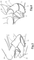
- the curved coverture 11 preferably covers the outer side of the leg portion 3, as shown in Figure 1 .
- coverture 11 can also cover the ankle portion 5 or the ankle portion 5 and the heel portion 8, as shown in Figures 2-6 .
- the curved coverture 11 preferably is a semi-rigid, bulge-shaped plate.
- the outer surface of this semi-rigid plate preferably is smooth, having a surface roughness less than 50 ⁇ m.
- the bulge is a simple curvature which extends over the entire height of the curved coverture 11.
- the semi-rigid plate is preferably made of polymer material. Even more preferably, thermoplastic polymers, such as thermoformed PVC.
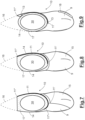
- coverture 11 The front and rear ends of coverture 11 are the leading edge 11' and the trailing edge 11', respectively, of an airfoil depicted in Figures 7-9 .
- a complete airfoil 16 is shown with a dashed line in Figures 7-9 .
- the airfoil provided by the curved coverture 11 only partially takes up the ideal surface of a complete airfoil 16, otherwise the boot would be too long at the back, thus creating mobility drawbacks and side effects during driving.
- the rear end could indeed create a sail effect such as to cause an excessive torsion of the rider's leg, especially when steering the motorcycle 20.
- coverture 11 allows limiting or eliminating the detachment of the fluid streamline at boot 10.
- connection of coverture 11 with boot 10 stabilizes the aerodynamic profile, despite the thrust applied by the air lapping it. This factor significantly contributes to the aerodynamic performance of the rider-motorcycle assembly 20, 30.
- coverture 11 is applied to the outer side of the boot and is monolithically connected thereto.
- the coverture 11 is connected to the outer side of the boot by means of an intermediate adhesive layer.
- coverture 11 can be directly sewn to boot 10. Therefore, the coverture 11 can be seen from the outside.
- the curved coverture 11 is a smooth plate, the surface opposes less aerodynamic resistance to air than the rest of boot 10, in particular than the inner side of the leg portion 3.
- Coverture 11 extends from the front to the back of the leg portion 3 of boot 10.
- Coverture 11 further defines the leading edge 11' and the trailing edge 11".
- boot 10 comprises a padding 17 and an outer layer 14 for covering the padding 17.
- Padding 17 is shaped so as to form a curvilinear shape at the front and squared at the back.
- the coverture 11 is arranged between the padding 17 and the outer layer 14.
- coverture 11 cannot be seen from the outside, since it is covered by the outer layer 14. This allows for an aesthetic uniformity of boot 10.
- the surface roughness of the leg portion 3 of boot 10 is uniform because the outer layer 14 entirely surrounds the leg portion 3.
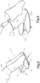
- coverture 11 is shaped in a similar manner to that of the first embodiment, but without the ogival profile 11′′′. In particular, the coverture 11 extends from the leading edge 11' to the trailing edge 11".
- the third embodiment similarly to the first one, has a padding 17 shaped with a simple front curvature profile and a flat rear profile, as better shown in Figures 4 and 5 .
- the curved coverture 11 forms a sharp edge with the rear surface of boot 10.
- the sharp edge can also affect the inner side of the boot, as shown in the embodiment in Figure 7 .
- the second embodiment shown in Figures 6 and 9 , comprises a traditional boot 10, on the outer surface 12 of which a curved coverture 11 is attached.
- This curved coverture 11 is a semi-rigid plate which comprises reversible fixing means 13. Unlike the first embodiment in which coverture 11 is permanently connected to boot 10, in this embodiment coverture 11 is removable.
- the fixing means can be snap fasteners, as shown in Figure 6 , or other fixing means 13, such as laces or Velcro fastening systems.
- These fixing means are arranged on the inner side of coverture 11 and on the outer surface 12 of boot 10 so as to obtain said fastening when they cooperate with each other.
- the reversible fixing means 13 are configured to allow the detachment of the removable coverture 11 if the motorcyclist 30 falls, thus without altering the regulatory approval compliance of boot 10.
- the coverture 11 can be made of a clear material in order not to alter the perceived appearance of boot 10.
- coverture 11 is a smooth plate which thus has a lower surface roughness than the surface roughness of the leg portion 3 of boot 10, which is made of leather, as in conventional motorcycle boots.
- the shape and position of the curved coverture 15 of boot 10 allows avoiding the detachment of the fluid streamline of air lapping the rider-motorcycle assembly 20, 30, as shown in Figure 11 .
- This figure depicts a section of the rider-motorcycle assembly 20, 30 with a plane parallel to the ground and taken at the height of the leg portion 3.
- a detachment of the fluid streamline occurs from the rider-motorcycle assembly 20, 30 at the boot.
- This detachment of the fluid streamline generates resistance forces which increase with speed in a more than proportional manner. Therefore, this undesired effect becomes apparent at high speeds, thus limiting the speed performance and increasing consumption.
- the boot 10 of one or more of the embodiments described above can comprise a further curved coverture 15 arranged at the vamp portion 9.
- the vamp portion 9, in particular the part thereof facing the outer side of boot 10, usually comprises a sacrificial element 18, in jargon referred to as a "soap bar" due to its shape.
- This element 18 is that usually coming into contact with the ground when the motorcyclist 30 leans over when the motorcycle 20 takes a bend.
- the strictly structural function of element 18 aerodynamically limits the performance of the rider-motorcycle assembly 20, 30.
- the protruding shape of the sacrificial element 18 is a protrusion of the vamp portion 9 which deflects the fluid streamline of air lapping the boot 10.
- boot 10 it is preferable for boot 10 to comprise a second curved coverture 15 which covers the vamp portion 9 of boot 10.
- this second curved coverture 15 simultaneously acts as a sacrificial element, thus avoiding the use of the conventional one.
- the shape of the padding of the first embodiment can correspond to that of the third embodiment or vice versa, as well as the second embodiment can comprise a second curved coverture 15 like the other embodiments.
Landscapes
- Health & Medical Sciences (AREA)
- General Health & Medical Sciences (AREA)
- Physical Education & Sports Medicine (AREA)
- Footwear And Its Accessory, Manufacturing Method And Apparatuses (AREA)
- Surgical Instruments (AREA)
- Sealing Devices (AREA)
- Valve Device For Special Equipments (AREA)
Claims (10)
- Stiefel (10) für einen Motorradfahrer, umfassend:- einen oberen Abschnitt (1), der vollständig mit einer Außensohle (2) verbunden ist;wobei der obere Abschnitt (1) einen Beinabschnitt (3) und einen Fußabschnitt (4) umfasst, die durch einen Knöchelabschnitt (5) vollständig miteinander verbunden sind;wobei der Beinabschnitt (3) einen Schienbeinabschnitt (6) und einen Wadenabschnitt (7) umfasst; undwobei der Fußabschnitt (4) einen Fersenabschnitt (8) und einen Oberlederabschnitt (9) umfasst;- eine gekrümmte Abdeckung (11), die dazu ausgelegt ist, eine Außenseite des Beinabschnitts (3) des Stiefels (10) zu bedecken; wobei die gekrümmte Abdeckung (11) als Tragfläche geformt ist und eine Vorderkante (11'), die in Übereinstimmung mit dem Schienbeinabschnitt (6) angeordnet ist, und eine Hinterkante (11") umfasst, die in Übereinstimmung mit dem Wadenabschnitt (7) angeordnet ist.
- Stiefel (10) nach Anspruch 1, wobei die gekrümmte Abdeckung (11) auch den Knöchelabschnitt (5) oder den Knöchelabschnitt (5) und den Fersenabschnitt (8) bedeckt.
- Stiefel (10) nach Anspruch 1 oder 2, wobei die gekrümmte Abdeckung (11) an der Außenoberfläche (12) des Stiefels (10) befestigt ist.
- Stiefel (10) nach einem der vorhergehenden Ansprüche, wobei die gekrümmte Abdeckung (11) Befestigungsmittel (13) umfasst, um die gekrümmte Abdeckung (11) an dem Stiefel (10) zu befestigen, wobei die Befestigungsmittel (13) vorzugsweise Schnürsenkel oder Druckknöpfe (13') umfassen.
- Stiefel (10) nach einem der vorhergehenden Ansprüche, wobei die gekrümmte Abdeckung (11) in dem Stiefel (10) eingebettet ist.
- Stiefel (10) nach Anspruch 5, wobei die gekrümmte Abdeckung (11) unter einer Außenschicht (14) des Stiefels (10) liegt, wobei die Außenschicht (14) vorzugsweise eine Lederschicht ist.
- Stiefel (10) nach einem der vorhergehenden Ansprüche, wobei die Hinterkante (11") der gekrümmten Abdeckung (11) eine scharfe Kante mit dem Oberlederabschnitt (9) definiert.
- Stiefel (10) nach einem der vorhergehenden Ansprüche, wobei die gekrümmte Abdeckung (11) eine geringere Oberflächenrauigkeit als die durchschnittliche Oberflächenrauigkeit des restlichen Beinabschnitts (3) des Stiefels (10) aufweist.
- Stiefel (10) nach einem der vorhergehenden Ansprüche, wobei die gekrümmte Abdeckung (11) ein spitzbogenförmiges Profil (11"') definiert, das in Übereinstimmung mit dem Schienbeinabschnitt (6) angeordnet ist.
- Stiefel (10) nach einem der vorhergehenden Ansprüche, wobei der Oberlederabschnitt (9) eine zweite gekrümmte Abdeckung (15) umfasst.
Applications Claiming Priority (2)
| Application Number | Priority Date | Filing Date | Title |
|---|---|---|---|
| IT102021000011051A IT202100011051A1 (it) | 2021-04-30 | 2021-04-30 | Stivale per motociclista |
| PCT/IB2022/052585 WO2022229726A1 (en) | 2021-04-30 | 2022-03-22 | Boot for a motorcyclist |
Publications (3)
| Publication Number | Publication Date |
|---|---|
| EP4329554A1 EP4329554A1 (de) | 2024-03-06 |
| EP4329554B1 true EP4329554B1 (de) | 2024-11-20 |
| EP4329554C0 EP4329554C0 (de) | 2024-11-20 |
Family
ID=76921240
Family Applications (1)
| Application Number | Title | Priority Date | Filing Date |
|---|---|---|---|
| EP22711667.0A Active EP4329554B1 (de) | 2021-04-30 | 2022-03-22 | Stiefel für einen motorradfahrer |
Country Status (4)
| Country | Link |
|---|---|
| US (1) | US12514327B2 (de) |
| EP (1) | EP4329554B1 (de) |
| IT (1) | IT202100011051A1 (de) |
| WO (1) | WO2022229726A1 (de) |
Families Citing this family (3)
| Publication number | Priority date | Publication date | Assignee | Title |
|---|---|---|---|---|
| EP4548793A1 (de) * | 2023-11-02 | 2025-05-07 | Crispi Sport S.r.l. | Abnehmbarer gamasche zum schutz von schuhwerk |
| IT202300004497U1 (it) * | 2023-11-02 | 2025-05-02 | Crispi Sport S R L | Struttura di ghetta rimovibile di protezione per calzature. |
| WO2026013517A1 (en) | 2024-07-08 | 2026-01-15 | Piaggio & C. S.P.A. | Straddle-type vehicle equipped with rear wings |
Family Cites Families (10)
| Publication number | Priority date | Publication date | Assignee | Title |
|---|---|---|---|---|
| US1907856A (en) * | 1929-10-05 | 1933-05-09 | Dunlop Rubber Co | Rubber footwear |
| US3514877A (en) * | 1968-06-26 | 1970-06-02 | Usm Corp | Boots |
| DE7405813U (de) * | 1973-03-15 | 1974-06-06 | Mazzarolo Sante Coste Di Maser | Fuß- und Beinschutzvorrichtung für Stiefel, Gamaschen od. dgl. |
| US5371903A (en) * | 1992-03-16 | 1994-12-13 | Wear And Tear, Inc. | Aerodynamic modules for cycling, skating and other speed sports |
| JP2006045738A (ja) | 2004-08-09 | 2006-02-16 | Yamaha Motor Co Ltd | 鞍乗型車両のライダー用衣服 |
| WO2011029050A1 (en) * | 2009-09-04 | 2011-03-10 | Dashamerica, Inc. D/B/A Pearl Izumi Usa, Inc. | Athletic shoe with integrated aerodynamic components |
| ES2542616T3 (es) | 2010-10-18 | 2015-08-07 | Pelletteria Ariston S.R.L. | Traje para motocicleta y solapa relevante |
| US9693599B2 (en) * | 2013-02-02 | 2017-07-04 | Fox Head, Inc. | Motorcycle boot |
| US20150033585A1 (en) * | 2013-08-05 | 2015-02-05 | Tracy C. Otus | Soccer cleat with leg protective structure |
| US10758006B2 (en) * | 2016-11-30 | 2020-09-01 | Nike, Inc. | Footwear heel structure |
-
2021
- 2021-04-30 IT IT102021000011051A patent/IT202100011051A1/it unknown
-
2022
- 2022-03-22 WO PCT/IB2022/052585 patent/WO2022229726A1/en not_active Ceased
- 2022-03-22 EP EP22711667.0A patent/EP4329554B1/de active Active
- 2022-03-22 US US18/288,117 patent/US12514327B2/en active Active
Also Published As
| Publication number | Publication date |
|---|---|
| IT202100011051A1 (it) | 2022-10-30 |
| EP4329554A1 (de) | 2024-03-06 |
| EP4329554C0 (de) | 2024-11-20 |
| US20240197029A1 (en) | 2024-06-20 |
| WO2022229726A1 (en) | 2022-11-03 |
| US12514327B2 (en) | 2026-01-06 |
Similar Documents
| Publication | Publication Date | Title |
|---|---|---|
| EP4329554B1 (de) | Stiefel für einen motorradfahrer | |
| US9901134B2 (en) | Aerodynamic bicycle shoe cover and pedal cover | |
| US9585432B2 (en) | Sport helmet | |
| US9125441B2 (en) | Sports garment with a seat pad, in particular for cycling | |
| US5822889A (en) | Bicycles shoes | |
| US9055779B2 (en) | Bicycle shoe | |
| US8079609B2 (en) | Aerodynamic brake system | |
| US20160007687A1 (en) | Shoe with a heel cap and/or ankle collar | |
| US11311073B2 (en) | Sole for cycling shoe | |
| EP2629636B1 (de) | Motorradkleidung und zugehöriger latz | |
| US5819315A (en) | Faired athletic garment | |
| WO1994019975A1 (en) | Clothing integrated aerodynamic modules for cycling, skating and other speed sports | |
| US8726425B2 (en) | Wake stabilizer for helmet and helmet | |
| US20130340151A1 (en) | Bicycle helmet with vent | |
| EP3818898B1 (de) | Aerodynamische vorrichtung für ein kleidungsstück | |
| CN216568608U (zh) | 一种钢架雪车运动鞋的鞋底和钢架雪车运动鞋 | |
| CN216568607U (zh) | 一种带鞋钉的鞋底和运动鞋 | |
| CN212185409U (zh) | 一种防护构件和防护鞋 | |
| JP4685626B2 (ja) | 二輪車の整流装置 | |
| CN222217298U (zh) | 一种透气鞋面以及鞋子 | |
| CN218571528U (zh) | 一种钢架雪车鞋的鞋底和钢架雪车鞋 | |
| JP3329584B2 (ja) | 自動二輪車搭乗用ブーツ | |
| CN223081195U (zh) | 一种鞋包头及应用该鞋包头的鞋 | |
| CN223247668U (zh) | 一种轻质透气的运动气动盔 | |
| CA2829837C (en) | Sport helmet |
Legal Events
| Date | Code | Title | Description |
|---|---|---|---|
| STAA | Information on the status of an ep patent application or granted ep patent |
Free format text: STATUS: UNKNOWN |
|
| STAA | Information on the status of an ep patent application or granted ep patent |
Free format text: STATUS: THE INTERNATIONAL PUBLICATION HAS BEEN MADE |
|
| PUAI | Public reference made under article 153(3) epc to a published international application that has entered the european phase |
Free format text: ORIGINAL CODE: 0009012 |
|
| STAA | Information on the status of an ep patent application or granted ep patent |
Free format text: STATUS: REQUEST FOR EXAMINATION WAS MADE |
|
| 17P | Request for examination filed |
Effective date: 20231017 |
|
| AK | Designated contracting states |
Kind code of ref document: A1 Designated state(s): AL AT BE BG CH CY CZ DE DK EE ES FI FR GB GR HR HU IE IS IT LI LT LU LV MC MK MT NL NO PL PT RO RS SE SI SK SM TR |
|
| DAV | Request for validation of the european patent (deleted) | ||
| DAX | Request for extension of the european patent (deleted) | ||
| GRAP | Despatch of communication of intention to grant a patent |
Free format text: ORIGINAL CODE: EPIDOSNIGR1 |
|
| STAA | Information on the status of an ep patent application or granted ep patent |
Free format text: STATUS: GRANT OF PATENT IS INTENDED |
|
| INTG | Intention to grant announced |
Effective date: 20240816 |
|
| GRAS | Grant fee paid |
Free format text: ORIGINAL CODE: EPIDOSNIGR3 |
|
| GRAA | (expected) grant |
Free format text: ORIGINAL CODE: 0009210 |
|
| STAA | Information on the status of an ep patent application or granted ep patent |
Free format text: STATUS: THE PATENT HAS BEEN GRANTED |
|
| AK | Designated contracting states |
Kind code of ref document: B1 Designated state(s): AL AT BE BG CH CY CZ DE DK EE ES FI FR GB GR HR HU IE IS IT LI LT LU LV MC MK MT NL NO PL PT RO RS SE SI SK SM TR |
|
| REG | Reference to a national code |
Ref country code: GB Ref legal event code: FG4D |
|
| REG | Reference to a national code |
Ref country code: CH Ref legal event code: EP |
|
| REG | Reference to a national code |
Ref country code: DE Ref legal event code: R096 Ref document number: 602022007961 Country of ref document: DE |
|
| REG | Reference to a national code |
Ref country code: IE Ref legal event code: FG4D |
|
| U01 | Request for unitary effect filed |
Effective date: 20241120 |
|
| U07 | Unitary effect registered |
Designated state(s): AT BE BG DE DK EE FI FR IT LT LU LV MT NL PT RO SE SI Effective date: 20241126 |
|
| U20 | Renewal fee for the european patent with unitary effect paid |
Year of fee payment: 4 Effective date: 20250224 |
|
| PG25 | Lapsed in a contracting state [announced via postgrant information from national office to epo] |
Ref country code: HR Free format text: LAPSE BECAUSE OF FAILURE TO SUBMIT A TRANSLATION OF THE DESCRIPTION OR TO PAY THE FEE WITHIN THE PRESCRIBED TIME-LIMIT Effective date: 20241120 Ref country code: IS Free format text: LAPSE BECAUSE OF FAILURE TO SUBMIT A TRANSLATION OF THE DESCRIPTION OR TO PAY THE FEE WITHIN THE PRESCRIBED TIME-LIMIT Effective date: 20250320 |
|
| PG25 | Lapsed in a contracting state [announced via postgrant information from national office to epo] |
Ref country code: ES Free format text: LAPSE BECAUSE OF FAILURE TO SUBMIT A TRANSLATION OF THE DESCRIPTION OR TO PAY THE FEE WITHIN THE PRESCRIBED TIME-LIMIT Effective date: 20241120 |
|
| PG25 | Lapsed in a contracting state [announced via postgrant information from national office to epo] |
Ref country code: NO Free format text: LAPSE BECAUSE OF FAILURE TO SUBMIT A TRANSLATION OF THE DESCRIPTION OR TO PAY THE FEE WITHIN THE PRESCRIBED TIME-LIMIT Effective date: 20250220 |
|
| PG25 | Lapsed in a contracting state [announced via postgrant information from national office to epo] |
Ref country code: GR Free format text: LAPSE BECAUSE OF FAILURE TO SUBMIT A TRANSLATION OF THE DESCRIPTION OR TO PAY THE FEE WITHIN THE PRESCRIBED TIME-LIMIT Effective date: 20250221 |
|
| PG25 | Lapsed in a contracting state [announced via postgrant information from national office to epo] |
Ref country code: PL Free format text: LAPSE BECAUSE OF FAILURE TO SUBMIT A TRANSLATION OF THE DESCRIPTION OR TO PAY THE FEE WITHIN THE PRESCRIBED TIME-LIMIT Effective date: 20241120 |
|
| PG25 | Lapsed in a contracting state [announced via postgrant information from national office to epo] |
Ref country code: RS Free format text: LAPSE BECAUSE OF FAILURE TO SUBMIT A TRANSLATION OF THE DESCRIPTION OR TO PAY THE FEE WITHIN THE PRESCRIBED TIME-LIMIT Effective date: 20250220 |
|
| PG25 | Lapsed in a contracting state [announced via postgrant information from national office to epo] |
Ref country code: SM Free format text: LAPSE BECAUSE OF FAILURE TO SUBMIT A TRANSLATION OF THE DESCRIPTION OR TO PAY THE FEE WITHIN THE PRESCRIBED TIME-LIMIT Effective date: 20241120 |
|
| PG25 | Lapsed in a contracting state [announced via postgrant information from national office to epo] |
Ref country code: SK Free format text: LAPSE BECAUSE OF FAILURE TO SUBMIT A TRANSLATION OF THE DESCRIPTION OR TO PAY THE FEE WITHIN THE PRESCRIBED TIME-LIMIT Effective date: 20241120 |
|
| PG25 | Lapsed in a contracting state [announced via postgrant information from national office to epo] |
Ref country code: CZ Free format text: LAPSE BECAUSE OF FAILURE TO SUBMIT A TRANSLATION OF THE DESCRIPTION OR TO PAY THE FEE WITHIN THE PRESCRIBED TIME-LIMIT Effective date: 20241120 |
|
| PLBE | No opposition filed within time limit |
Free format text: ORIGINAL CODE: 0009261 |
|
| STAA | Information on the status of an ep patent application or granted ep patent |
Free format text: STATUS: NO OPPOSITION FILED WITHIN TIME LIMIT |
|
| PG25 | Lapsed in a contracting state [announced via postgrant information from national office to epo] |
Ref country code: MC Free format text: LAPSE BECAUSE OF FAILURE TO SUBMIT A TRANSLATION OF THE DESCRIPTION OR TO PAY THE FEE WITHIN THE PRESCRIBED TIME-LIMIT Effective date: 20241120 |
|
| 26N | No opposition filed |
Effective date: 20250821 |
|
| REG | Reference to a national code |
Ref country code: CH Ref legal event code: H13 Free format text: ST27 STATUS EVENT CODE: U-0-0-H10-H13 (AS PROVIDED BY THE NATIONAL OFFICE) Effective date: 20251023 |
|
| PG25 | Lapsed in a contracting state [announced via postgrant information from national office to epo] |
Ref country code: CH Free format text: LAPSE BECAUSE OF NON-PAYMENT OF DUE FEES Effective date: 20250331 |
|
| PG25 | Lapsed in a contracting state [announced via postgrant information from national office to epo] |
Ref country code: IE Free format text: LAPSE BECAUSE OF NON-PAYMENT OF DUE FEES Effective date: 20250322 |
|
| U20 | Renewal fee for the european patent with unitary effect paid |
Year of fee payment: 5 Effective date: 20260122 |