EP4329367B1 - Verfahren zum verschieben einer pdu-sitzung von einem nicht-3gpp- zu einem 3gpp-zugang - Google Patents
Verfahren zum verschieben einer pdu-sitzung von einem nicht-3gpp- zu einem 3gpp-zugang Download PDFInfo
- Publication number
- EP4329367B1 EP4329367B1 EP23204349.7A EP23204349A EP4329367B1 EP 4329367 B1 EP4329367 B1 EP 4329367B1 EP 23204349 A EP23204349 A EP 23204349A EP 4329367 B1 EP4329367 B1 EP 4329367B1
- Authority
- EP
- European Patent Office
- Prior art keywords
- pdu session
- smf
- amf
- access
- information
- Prior art date
- Legal status (The legal status is an assumption and is not a legal conclusion. Google has not performed a legal analysis and makes no representation as to the accuracy of the status listed.)
- Active
Links
Images


Classifications
-
- H—ELECTRICITY
- H04—ELECTRIC COMMUNICATION TECHNIQUE
- H04W—WIRELESS COMMUNICATION NETWORKS
- H04W36/00—Hand-off or reselection arrangements
- H04W36/0005—Control or signalling for completing the hand-off
- H04W36/0011—Control or signalling for completing the hand-off for data sessions of end-to-end connection
- H04W36/0022—Control or signalling for completing the hand-off for data sessions of end-to-end connection for transferring data sessions between adjacent core network technologies
-
- H—ELECTRICITY
- H04—ELECTRIC COMMUNICATION TECHNIQUE
- H04W—WIRELESS COMMUNICATION NETWORKS
- H04W36/00—Hand-off or reselection arrangements
- H04W36/0005—Control or signalling for completing the hand-off
- H04W36/0011—Control or signalling for completing the hand-off for data sessions of end-to-end connection
- H04W36/0033—Control or signalling for completing the hand-off for data sessions of end-to-end connection with transfer of context information
-
- H—ELECTRICITY
- H04—ELECTRIC COMMUNICATION TECHNIQUE
- H04W—WIRELESS COMMUNICATION NETWORKS
- H04W36/00—Hand-off or reselection arrangements
- H04W36/0005—Control or signalling for completing the hand-off
- H04W36/0055—Transmission or use of information for re-establishing the radio link
- H04W36/0079—Transmission or use of information for re-establishing the radio link in case of hand-off failure or rejection
-
- H—ELECTRICITY
- H04—ELECTRIC COMMUNICATION TECHNIQUE
- H04W—WIRELESS COMMUNICATION NETWORKS
- H04W36/00—Hand-off or reselection arrangements
- H04W36/0005—Control or signalling for completing the hand-off
- H04W36/0083—Determination of parameters used for hand-off, e.g. generation or modification of neighbour cell lists
- H04W36/00837—Determination of triggering parameters for hand-off
-
- H—ELECTRICITY
- H04—ELECTRIC COMMUNICATION TECHNIQUE
- H04W—WIRELESS COMMUNICATION NETWORKS
- H04W36/00—Hand-off or reselection arrangements
- H04W36/24—Reselection being triggered by specific parameters
- H04W36/32—Reselection being triggered by specific parameters by location or mobility data, e.g. speed data
-
- H—ELECTRICITY
- H04—ELECTRIC COMMUNICATION TECHNIQUE
- H04W—WIRELESS COMMUNICATION NETWORKS
- H04W76/00—Connection management
- H04W76/10—Connection setup
- H04W76/18—Management of setup rejection or failure
-
- H—ELECTRICITY
- H04—ELECTRIC COMMUNICATION TECHNIQUE
- H04W—WIRELESS COMMUNICATION NETWORKS
- H04W36/00—Hand-off or reselection arrangements
- H04W36/12—Reselecting a serving backbone network switching or routing node
-
- H—ELECTRICITY
- H04—ELECTRIC COMMUNICATION TECHNIQUE
- H04W—WIRELESS COMMUNICATION NETWORKS
- H04W36/00—Hand-off or reselection arrangements
- H04W36/13—Cell handover without a predetermined boundary, e.g. virtual cells
-
- H—ELECTRICITY
- H04—ELECTRIC COMMUNICATION TECHNIQUE
- H04W—WIRELESS COMMUNICATION NETWORKS
- H04W36/00—Hand-off or reselection arrangements
- H04W36/14—Reselecting a network or an air interface
- H04W36/144—Reselecting a network or an air interface over a different radio air interface technology
-
- H—ELECTRICITY
- H04—ELECTRIC COMMUNICATION TECHNIQUE
- H04W—WIRELESS COMMUNICATION NETWORKS
- H04W36/00—Hand-off or reselection arrangements
- H04W36/24—Reselection being triggered by specific parameters
- H04W36/32—Reselection being triggered by specific parameters by location or mobility data, e.g. speed data
- H04W36/322—Reselection being triggered by specific parameters by location or mobility data, e.g. speed data by location data
-
- H—ELECTRICITY
- H04—ELECTRIC COMMUNICATION TECHNIQUE
- H04W—WIRELESS COMMUNICATION NETWORKS
- H04W76/00—Connection management
- H04W76/10—Connection setup
- H04W76/12—Setup of transport tunnels
Definitions
- the S-GW 52 may play a role of an anchor point for mobility with another 3GPP network (i.e., a RAN defined prior to 3GPP release-8, for example, a UTRAN or Global System for Mobile communication (GSM)/Enhanced Data rates for Global Evolution (EDGE) Radio Access Network (GERAN)).
- a RAN defined prior to 3GPP release-8, for example, a UTRAN or Global System for Mobile communication (GSM)/Enhanced Data rates for Global Evolution (EDGE) Radio Access Network (GERAN)).
- GSM Global System for Mobile communication
- EDGE Enhanced Data rates for Global Evolution
- GERAN Global System for Mobile communication
- the SGSN handles all packet data, such as a user's mobility management and authentication for different access 3GPP networks (e.g., a GPRS network and an UTRAN/GERAN).
- 3GPP networks e.g., a GPRS network and an UTRAN/GERAN.
- a terminal having an IP capability can access an IP service network (e.g., IMS), provided by a service provider (i.e., an operator), via various elements within an EPC based on non-3GPP access as well as based on 3GPP access.
- IMS IP service network
- a service provider i.e., an operator
- LTE Long-Term Evolution
- LTE-A Long-Term Evolution-Advanced
- 5G fifth-generation
- the fifth-generation communication defined by the International Telecommunication Union (ITU) refers to providing a maximum data transmission speed of 20Gbps and a maximum transmission speed of 100Mbps per user in anywhere. It is officially called “IMT-2020” and aims to be released around the world in 2020.
- the fifth-generation mobile communication supports multiples numerologies (and/or multiple Subcarrier Spacings (SCS)) to support various 5G services. For example, if SCS is 15 kHz, wide area can be supported in traditional cellular bands, and if SCS is 30 kHz/60 kHz, dense-urban, lower latency, and wider carrier bandwidth can be supported. If SCS is 60 kHz or higher, bandwidths greater than 24.25 GHz can be supported to overcome phase noise.
- numerologies and/or multiple Subcarrier Spacings (SCS)
- SCS Subcarrier Spacings
- FR1 may include a band of 410 MHz to 7125 MHz as shown in Table 3 below. That is, FR1 may include a frequency band of above 6 GHz (or, 5850, 5900, 5925 MHz, etc.). For example, a frequency band of above 6 GHz (or, 5850, 5900, 5925 MHz, etc.) included in FR1 may include an unlicensed band. The unlicensed band may be used for various purposes, e.g., for communication for a vehicle (e.g., autonomous driving). [Table 3] Frequency Range designation Corresponding frequency range Subcarrier Spacing FR1 410MHz - 7125MHz 15, 30, 60kHz FR2 24250MHz - 52600MHz 60, 120, 240kHz
- the eMBB relates to a usage scenario that requires a mobile ultra-wideband.
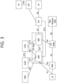
- the 5G Core network may include various components, part of which are shown in FIG. 2 , including an Access and mobility Management Function (AMF) 41, a Session Management Function (SMF) 42, a Policy Control Function (PCF) 43, a User Plane Function (UPF) 44, an Application Function (AF) 45, a Unified Data Management (UDM) 46 and a Non-3GPP Interworking Function (N3IWF) 49.
- AMF Access and mobility Management Function
- SMF Session Management Function
- PCF Policy Control Function
- UPF User Plane Function
- AF Application Function
- UDM Unified Data Management
- N3IWF Non-3GPP Interworking Function
- a UE 10 is connected to a data network via the UPF 44 through a Next Generation Radio Access Network (NG-RAN), i.e., gNB or base station.
- NG-RAN Next Generation Radio Access Network
- the UE is connected to a Data Network (DN) through a NG-RAN.
- DN Data Network
- the Network Slice Selection Function (NSSF) node refers to a node for performing network slicing as described below.
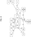
- FIG. 4 illustrates an architecture that allows the UE to simultaneously access two data networks using one PDU session.
- N4 is a reference point between SMF and UPF.
- N8 is a reference point between UDM and AMF.
- N12 is a reference point between AMF and AUSF.
- N13 is a reference point between UDM and AUSF.
- N14 is a reference point between AMFs.
- N15 is a reference point between PCF and AMF.
- N22 is a reference point between AMF and NSSF.
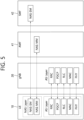
- FIG. 5 is another exemplary diagram showing a structure of a radio interface protocol between a UE and a gNB.
- the first layer provides an information transfer service using a physical channel.
- the physical layer is connected to an upper medium access control layer through a transport channel, and data between the medium access control layer and the physical layer is transmitted through the transport channel.
- data is transmitted between different physical layers, that is, between the physical layers of a transmitting side and a receiving side through a physical channel.
- the third layer includes Radio Resource Control (hereinafter abbreviated as RRC) layer.
- RRC Radio Resource Control
- the RRC layer is defined only in the control plane and is in charge of control of logical channels, transport channels, and physical channels related to configuration, reconfiguration and release of radio bearers.
- RB refers to a service provided by the second layer for data transfer between the UE and the E-UTRAN.
- the Non-Access Stratum (NAS) layer performs functions such as connection management (session management) and mobility management.
- the handover may fail if resource reservation in the access network fails.
- At least one of A, B and C may mean “only A”, “only B”, “only C”, or “any combination of A, B and C”.
- at least one of A, B or C or “at least one of A, B and/or C” may mean “at least one of A, B and C”.
- an ID of the UE may be obtained from the UE.
- the AMF may forward (or transfer) a PEI (IMEISV) to a UDM, SMF, and PCF.
- PEI PEISV
- any AMF is selected according to a local policy, and the registration request is forwarded (or transferred) by using the selected AMF. If the selected AMF cannot provide service to the UE, the selected AMF may select another AMF that is more appropriate for the UE.
- the RAN transmits an N2 message to a new AMF.
- the N2 message includes an N2 parameter and a registration request.
- the registration request may include a registration type, a subscriber permanent identifier or temporary user ID, a security parameter, NSSAI, MICO mode default settings (or configuration), and so on.
- the N2 parameter includes location information related to a cell in which the UE is camping, a cell identifier, and a RAT type.
- the new AMF transmits an Identity Request message to the UE.
- the UE transmits an Identity Response message including the SUPI to the new AMF.
- the new AMF may transmit an information response message to the previous (or old) AMF.
- an Identity Request message may be transmitted in order to allow the AMF to search the PEI.
- the new AMF checks an ME identifier.
- Step 14 which will be described later on, is performed, the new AMF selects a UDM based on the SUPI.
- the PCF transmits a UE Context Establishment Acknowledged message to the new AMF.
- the new AMF transmits an N11 request message to the SMF.
- the new AMF transmits an N11 response message to the SMF.
- the previous (or old) AMF transmits a UE Context Termination Request message to the PCF.
- the PCF may transmit a UE Context Termination Request message to the previous (or old) AMF.
- the new AMF transmits a Registration Accept message to the UE.
- the Registration Accept message may include a temporary user ID, registration area, mobility restriction, PDU session status, NSSAI, periodic registration update timer, and allowed MICO mode.
- the temporary user ID may be further included in the Registration Accept message.
- information indicating the mobility restriction may be additionally included in the Registration Accept message.
- the AMF may include information indicating the PDU session status for the UE in the Registration Accept message.
- the UE may remove any internal resource being related to a PDU session that is not marked as being active from the received PDU session status. If the PDU session status information is included in the Registration Request, the AMF may include the information indicating the PDU session status to the UE in the Registration Accept message.
- the UE transmits a Registration Complete message to the new AMF.
- PDU Session Establishment procedure two different types of PDU Session Establishment procedures may exist as described below.
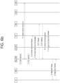
- FIGS. 7a and 7b are a signal flowchart illustrating an exemplary PDU session establishment procedure.
- the procedure shown in FIGS. 7a and 7b assumes that the UE has already registered on the AMF according to the registration procedure shown in FIG. 6 . Therefore, it is assumed that the AMF has already acquired user subscription data from UDM.
- the UE includes S-NSSAI from allowed NSSAI for the current access type. If information on the mapped NSSAI has been provided to the UE, the UE may provide both S-NSSAI based on the allowed NSSAI and the corresponding S-NSSAI based on the information on the mapped NSSAI.
- the information on the mapped NSSAI is information on mapping of each S-NSSAI in the allowed NSSAI to the S-NASSI in the NSSAI set up for Home Public Land Mobile Network (HPLMN).
- HPLMN Home Public Land Mobile Network
- the SMF determines that the corresponding request is caused by a handover between the 3GPP access and the non-3GPP access.
- the SMF may identify the existing PDU session based on the PDU session ID.
- the SMF may request the subscription data.
- the SMF provides information on the policy control request trigger condition by performing the SM policy association modification procedure.
- the N2 SM information may include PDU Session ID, QoS Flow ID (QFI), QoS Profile(s), CN Tunnel Info, S-NSSAI from the Allowed NSSAI, Session-AMBR, PDU Session Type, User Plane Security Enforcement information, UE Integrity Protection Maximum Data Rate.
- QFI QoS Flow ID
- QoS Profile(s) QoS Profile(s)
- CN Tunnel Info CN Tunnel Info
- S-NSSAI from the Allowed NSSAI Session-AMBR
- PDU Session Type User Plane Security Enforcement information
- UE Integrity Protection Maximum Data Rate UE Integrity Protection Maximum Data Rate
- the N1 SM container may include a PDU session establishment accept message.
- the PDU session establishment accept message may include an allowed QoS rule, SSC mode, S-NSSAI, and an assigned IPv4 address.
- the AMF transmits an N2 PDU Session Request message to the RAN.
- the message may include N2 SM information and an NAS message.
- the NAS message may include a PDU session ID and a PDU Session Establishment Accept message.
- the RAN may perform a specific signaling exchange with a UE being related to the information received from the SMF.
- the RAN forwards the NAS message, which is provided in the step 10.
- the NAS message may include a PDU session ID and N1 SM information.
- the N1 SM information may include a PDU Session Establishment Accept message.
- the RAN transmits the NAS message to the UE only in a case where a needed RAN resource is configured and allocation of RAN tunnel information is successful.
- the AMF may transmit Nsmf_PDUSession_UpdateSMContext Request message to the SMF.
- the Nsmf_PDUSession_UpdateSMContext Request message may include N2 SM information.
- the AMF may forward the N2 SM information received from the RAN to the SMF.
- the SMF transmits Nsmf_PDUSession_UpdateSMContext Response message to the AMF.
- the SMF transmits Nsmf_PDUSession_SMContextStatusNotify message.
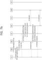
- FIGS. 8a and 8b show a modification procedure for a PDU session.
- the MA PDU session may be established/managed based on the PDU session modification procedure.
- the UE may initiate a PDU session modification procedure by sending a NAS message.
- the NAS message may include an N1 SM container.
- the N1 SM container may include a PDU session modification request message, a PDU session ID, and information on the maximum data rate for integrity protection of the UE.
- the PDU session modification request message may include a PDU session ID, packet filters, requested QoS information, 5GSM core network capabilities, and the number of packet filters.
- the maximum data rate for integrity protection of the UE indicates the maximum data rate at which the UE can support UP integrity protection.
- the number of packet filters indicates the number of packet filters supported for QoS rules.
- the NAS message is transmitted to an appropriate AMF according to the location information of the UE via the RAN. Then, the AMF transmits an Nsmf_PDUSession_UpdateSMContext message to the SMF.
- the message may include a Session Management (SM) context ID and an N1 SM container.
- the N1 SM container may include a PDU session modification request message.
- the PCF may inform the SMF of the policy change by initiating an SM policy association modification procedure.
- the UDM may update the subscription data of the SMF by transmitting a Nudm_SDM_Notification message.
- the SMF may update the session management subscriber data and transmit an ACK message to the UDM.
- SMF When initiated by SMF among network nodes, SMF may trigger QoS update.
- the SMF may perform a PDU session modification procedure.
- the AN may notify the SMF when an AN resource to which a QoS flow is mapped is released.
- the AN may transmit an N2 message to the AMF.
- the N2 message may include a PDU session ID and N2 SM information.
- the N2 SM information may include QoS Flow ID (QFI), user location information, and an indication indicating that the QoS flow is released.
- the AMF may transmit an Nsmf_PDUSession_UpdateSMContext message.
- the message may include SM context ID and N2 SM information.
- the SMF may transmit a report on the subscription event by performing the SM policy association modification procedure. If the PDU session modification procedure is triggered by 1b or 1d, this step may be skipped. If a dynamic PCC is not deployed in the network, the SMF may apply an internal policy to decide to change the QoS profile.
- Steps 3 to 7, which will be described later, may not be performed when the PDU session modification requires only the UPF operation.
- the SMF may respond to the AMF by sending an Nsmf_PDUSession_UpdateSMContext message.
- the message may include N2 SM information and an N2 SM container.
- the N2 SM information may include a PDU session ID, QFI, QoS profile, and session-AMBR.
- the N1 SM container may include a PDU session modification command.
- the PDU session modification command may include a PDU session ID, a QoS rule, a QuS rule operation, QoS flow level QoS parameters, and a session-AMBR.
- the N2 SM information may include information to be transmitted by the AMF to the AN.
- the N2 SM information may include a QFI and a QoS profile to notify the AN that one or more QoS flows are added or modified. If the PDU session modification is requested by the UE for which the user plane resource is not configured, the N2 SM information to be delivered to the AN may include information on the establishment of the user plane resource.
- the N1 SM container may include a PDU session modification command to be delivered by the AMF to the UE.
- the PDU session modification command may include QoS rules and QoS flow level QoS parameters.
- the SMF may transmit a Namf_Communication_N1N2MessageTransfer message.
- the message may include N2 SM information and N1 SM container.
- the N2 SM information may include a PDU session ID, QFI, QoS profile, and session-AMBR.
- the N1 SM container may include a PDU session modification command.
- the PDU session modification command may include a PDU session ID, a QoS rule, and a QoS flow level QoS parameters.
- the AMF updates and stores the UE context based on the Namf_Communication_N1N2MessageTransfer message, and then steps 3 to 7 described later may be skipped.
- the AMF may transmit an N1 message to synchronize the UE context with the UE.
- the AMF may transmit an N2 PDU session request message to the AN.
- the N2 PDU session request message may include N2 SM information received from the SMF and a NAS message.
- the NAS message may include a PDU session ID and an N1 SM container.
- the N1 SM container may include a PDU session modification command.
- the AN performs AN signaling exchange with the UE related to the information received from the SMF.
- NG-RAN i.e., gNB or base station
- an RRC connection reconfiguration procedure may be performed with the UE.
- the SMF transmits an N4 session modification request message to the UPF to update the N4 session of the UPF included in the PDU session modification.
- the UE transmits a NAS message in response to receiving the PDU session modification command.
- the NAS message may include a PDU session ID and an N1 SM container.
- the N1 SM container may include a PDU session modification command ACK.
- the SMF informs the AMF that the PDU session has been released.
- AMF deletes all contexts for the corresponding PDU session.
- the UE can no longer send and receive NAS signaling for the PDU session.
- the UE thinks that the PDU session has been released from the network and locally releases the PDU session. In this case, since the AMF does not send signaling for local release to the SMF, there is a problem in that the PDU session context remains in the UPF and the access network.
- the AMF may not immediately update the access type of the PDU session, but may later update the access type when receiving a notification message from the SMF informing that the handover has been successfully performed. In this case, the AMF needs to remember that the handover is in progress.
- the AMF may recognize that the handover has failed.
- the AMF transmits the NAS signaling on an access type (e.g., non-3GPP access) other than the access type (e.g., 3GPP access) of the current PDU session.
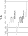
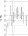
- FIG. 9 is an exemplary diagram illustrating an example in which establishment of a new PDU session fails.
- Step 1 The UE transmits a PDU session establishment request message to the AMF through the NG-RAN.
- the SMF should not notify that the PDU session is released. That is, the SMF needs to have different behavior according to the request type. If the request type is set to "initial request”, the SMF may notify the release of the PDU session. If the request type is set to "Existing PDU Session", the SMF needs not to notify the release.
- the SMF notifies the AMF that the handover procedure is failed so that the AMF updates access type of the PDU session.
- Nsmf_PDUSession_SMContextStatusNotify message may be used to notify the handover failure.
- the AMF needs to update access type of the PDU session accordingly, e.g., 3GPP access to non-3GPP access and vice versa.
- the SMF explicitly notifies access type of the PDU session.
- the former method may have issue in case of abnormal scenario, the latter method, i.e., the AMF updates access type of the PDU session to based on information from the SMF, may be preferred.
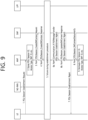
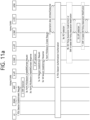
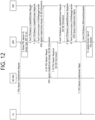
- FIGS. 10a and 10b are exemplary diagrams illustrating a PDU session establishment procedure for non-roaming and Local Breakout (LBO) scheme roaming.
- LBO Local Breakout
- Step 18 The SMF transmits Nsmf_PDUSession_SMContextStatusNotify message to the AMF.
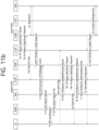
- FIGS. 11a and 11b are exemplary diagrams illustrating a PDU session establishment procedure for HR scheme roaming.
- Step 3 In LBO roaming case, if the V-SMF responds to the AMF indicating that the V-SMF is not able to process some part of the N1 SM information, the AMF proceeds steps for HR roaming scheme and may select an SMF in the VPLMN different from the V-SMF selected earlier.
- Step 3a The AMF also provides the identity of the H-SMF it has selected in step 2 and both the VPLMN S-NSSAI from the Allowed NSSAI and the corresponding S-NSSAI of the HPLMN.
- the H-SMF is provided when the PDU session is HR scheme.
- the AMF may also provide the identity of alternative H-SMFs.
- the AMF may include the H-PCF ID and the V-SMF may pass it to the H-SMF.
- Step 3b If the PDU session type is "Unstructured” and the V-SMF received an "Invoke NEF” flag, then it may skip steps 4 and 5.
- Step 4 The V-SMF selects a UPF in VPLMN.
- Step 5 The V-SMF initiates an N4 session establishment procedure with the selected V-UPF.
- Step 5b The V-UPF acknowledges by sending an N4 session establishment response message. If CN Tunnel Info is allocated by the V-UPF, the CN Tunnel Info may be provided to the V-SMF.
- the V-SMF may transmit Nsmf_PDUSession_Create request message to the H-SMF.
- the message may include SUPI, GPSI, V-SMF SM context ID, DNN, S-NSSAI with the value defined by the HPLMN, PDU session ID, V-SMF ID, V-CN-Tunnel-Info, PDU session type, PCO, number of packet filters, user location information, access type, PCF ID, SM PDU DN request container, DNN selection mode, AMF ID, etc.
- Protocol Configuration Options may contain information that the H-SMF may need to properly establish the PDU session (e.g., SSC mode or SM PDU DN request container to be used to authenticate the UE).
- the V-SMF SM context ID contains the addressing information it has allocated for service operations related with this PDU session.
- the H-SMF stores an association of the PDU session and V-SMF Context ID.
- Steps 7-12b These steps are the same as steps 4 to 10 of FIG. 7a . However, there are differences as follows.
- Step 12c This step is the same as step 16c of FIG. 7b .
- the H-SMF may indicate it to the V-SMF by including always-on PDU session granted indication that the PDU Session is an always-on PDU Session.
- the H-CN Tunnel Info contains the tunnel information for uplink traffic towards the H-UPF.
- Steps 14-18 These steps are the same as steps 11-15 of FIG. 7b . Hereinafter, only the different parts will be described.
- the V-SMF stores an association of the PDU session and H-SMF ID.
- the V-SMF further checks whether the PDU session can be established as an always-on PDU session based on local policies. The V-SMF notifies the UE whether the PDU session is an always-on PDU session or not via the always-on PDU session granted indication in the PDU session establishment accept message.
- Step 20 This step is the same as step 17 of FIG. 7b . However, there are differences as follows.
- Step 21 This step is same as step 18 in FIG. 7b .
- the H-SMF delivers IPv6 address configuration to the UE through the H-UPF and the V-UPF in VPLMN.
- the H-SMF generates an IPv6 Router Advertisement and sends it to the UE via N4 and the H-UPF and V-UPF.
- Step 24 This step is the same as step 20 of FIG. 7b . However, there are differences as follows.
- Step 6 The AMF transmits the N2 SM information and the PDU session establishment accept message received from the SMF to the NG-RAN.
- Step 7 the request of the SMF may be rejected due to lack of radio resources.
- the NG-RAN does not deliver the PDU session establishment accept message received from the SMF to the UE, and notifies that the PDU session is not setup in response to the N2 SM information.
- Step 10-11 The SMF knows that the user plane setup has failed based on the response from the NG-RAN and transmits a PDU session establishment reject message to inform that the UE's request has not been accepted.
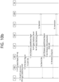
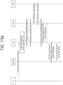
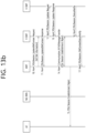
- FIGS. 13a and 13b are exemplary diagrams illustrating an example in which handover from non-3GPP access to 3GPP access fails in the HR roaming scheme.
- Step 1 It is assumed that the UE has established a PDU session through non-3GPP access.
- the UE transmits a PDU session establishment request message including the PDU session ID of the non-3GPP access PDU session and the request type set to "Existing PDU Session" in order to handover the PDU session on the non-3GPP access to the 3GPP access.
- Step 2 The AMF updates the access type information of the PDU session from the non-3GPP access to the 3GPP access based on the PDU session ID information in the message received from the UE.
- Step 3-4 The AMF selects the V-SMF based on information (e.g., DNN, S-NSSAI) in the message received from the UE, and also selects the H-SMF based on the PDU session ID information of the UE.
- the AMF also transmits the request type sent by the UE while delivering the PDU session establishment request message to the V-SMF. At this time, the H-SMF information selected by the AMF is also transmitted.
- the V-SMF delivers the information sent by the AMF to the H-SMF identified based on the H-SMF information received from the AMF.
- the H-SMF may determine that the UE requests handover of a PDU session on the non-3GPP access to the 3GPP access based on the PDU session ID information in the message received from the UE and the request type set to "Existing PDU Session".
- the H-SMF informs the V-SMF that the UE's request is allowed.
- Step 7 The V-SMF generates N2 SM information for user plane setup with the 3GPP access while allowing the UE's request, and transmits it to the AMF along with a PDU session establishment accept message.
- Step 8 The AMF transmits the N2 SM information and the PDU session establishment accept message received from the V-SMF to the NG-RAN.
- Step 9 the request of the V-SMF may be rejected due to lack of radio resources.
- the NG-RAN does not deliver the PDU session establishment accept message received from the V-SMF to the UE, and includes information informing that the PDU session is not setup in response to the N2 SM information.
- the SMF When the SMF receives a PDU session establishment request message including a request type set to "initial request”, if the PDU session establishment fails, the SMF may transmit an Nsmf_PDUSession_SMcontextStatusNotify message to the AMF to inform that the PDU session is released.
- the AMF may transmit NAS signaling in an access type (e.g., non-3GPP access) opposite to the access type (e.g., 3GPP access) of the PDU session.
- an access type e.g., non-3GPP access
- the access type e.g., 3GPP access
- the AMF may recognize that the handover of the PDU session has failed and determine that the handover procedure is over.
- the AMF may determine that the handover has ended successfully.
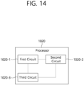
- a processor 1020 in which the disclosure of the present specification is implemented may include a plurality of circuitry to implement the proposed functions, procedures and/or methods described herein.
- the processor 1020 may include a first circuit 1020-1, a second circuit 1020-2, and a third circuit 1020-3.
- the processor 1020 may include more circuits. Each circuit may include a plurality of transistors.
- the processor 1020 may be referred to as an Application-Specific Integrated Circuit (ASIC) or an Application Processor (AP), and includes at least one of a Digital Signal Processor (DSP), a Central Processing Unit (CPU), and a Graphics Processing Unit (GPU).
- ASIC Application-Specific Integrated Circuit
- AP Application Processor
- DSP Digital Signal Processor
- CPU Central Processing Unit
- GPU Graphics Processing Unit
- the processor may be included in the UE, the base station, the AMF or the SMF.
- the first circuit 1020-1 of the processor included in the AMF may receive a Session Management (SM) context status notify message from a Session Management Function (SMF).
- SM Session Management
- SMF Session Management Function
- the second circuit 1020-2 of the processor included in the AMF may update an access type related to the PDU session based on the SM context status notify message.
- the third circuit 1020-3 of the processor included in the AMF may receive a PDU session establishment request message from a User Equipment (UE).
- the PDU session establishment request message may include a request type set to "Existing PDU Session".
- the SM context status notify message may include information informing that the handover of the PDU session has failed.
- Updating the access type may be performed based on the information on the access type included in the SM context status notify message.
- the access type related to the PDU session may be updated to the non-3GPP access, based on the failure of handover of the PDU session between the non-3GPP access and the 3GPP access.
- the fourth circuit (not shown) of the processor included in the AMF may not release the PDU session based on the failure of the PDU session establishment procedure.
- the failure of the PDU session establishment procedure may be based on a resource setup failure of an Access Network (AN).
- AN Access Network
- the SM context status notify message may be transmitted based on a failure of a Protocol Data Unit (PDU) session establishment procedure,
- PDU Protocol Data Unit
- the SM context status notify message may include information on an access type related to the PDU session.
- the SM context status notify message may include information informing that the handover of the PDU session has failed.
- the SM context status notify message may include information on the access type for the PDU session after a failure of the handover.
- the information on the access type for the PDU session may indicate the non-3GPP access, based on the failure of the handover of the PDU session between the non-3GPP access and the 3GPP access.
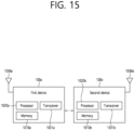
- the first device 100a may be a UE described in the disclosure of the present specification.
- the first device 100a may be a base station, a network node, a transmission terminal, a reception terminal, a wireless device, a wireless communication device, a vehicle, a vehicle on which a self-driving function is mounted, a connected car, a drone (Unmanned Aerial Vehicle (UAV)), an Artificial Intelligence (AI) module, a robot, an Augmented Reality (AR) device, a Virtual Reality (VR) device, a Mixed Reality (MR) device, a hologram device, a public safety device, an MTC device, an IoT device, a medical device, a FinTech device (or financial device), a security device, a climate/environment device, a device related to 5G service or a device related to the fourth industrial revolution field.
- UAV Unmanned Aerial Vehicle
- AI Artificial Intelligence
- AR Augmented Reality
- VR Virtual Reality
- MR Mixed Reality
- hologram device
- the drone may be a flight vehicle that flies by a wireless control signal without a person being on the flight vehicle.
- the VR device may include a device implementing the object or background of a virtual world.
- the AR device may include a device implementing the object or background of a virtual world by connecting it to the object or background of the real world.
- the MR device may include a device implementing the object or background of a virtual world by merging it with the object or background of the real world.
- the hologram device may include a device implementing a 360-degree stereographic image by recording and playing back stereographic information using the interference phenomenon of a light beam generated when two lasers called holography are met.
- the first device 100a may include at least one processor such as a processor 1020a, at least one memory such as memory 1010a, and at least one transceiver such as a transceiver 1031a.
- the processor 1020a may perform the above-described functions, procedures, and/or methods.
- the processor 1020a may perform one or more protocols.
- the processor 1020a may perform one or more layers of a radio interface protocol.
- the memory 1010a is connected to the processor 1020a, and may store various forms of information and/or instructions.
- the transceiver 1031a is connected to the processor 1020a, and may be controlled to transmit and receive radio signals.
- the second device 100b may include at least one processor such as a processor 1020b, at least one memory device such as memory 1010b, and at least one transceiver such as a transceiver 1031b.
- the processor 1020b may perform the above-described functions, procedures and/or methods.
- the processor 1020b may implement one or more protocols.
- the processor 1020b may implement one or more layers of a radio interface protocol.
- the memory 1010b is connected to the processor 1020b, and may store various forms of information and/or instructions.
- the transceiver 1031b is connected to the processor 1020b and may be controlled transmit and receive radio signals.
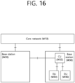
- FIG. 16 illustrates a block diagram of a network node according to an embodiment.
- base stations W20 and W30 may be connected to a core network W10.
- the base station W30 may be connected to a neighbor base station W20.
- an interface between the base stations W20 and W30 and the core network W10 may be referred to as an NG.
- An interface between the base station W30 and the neighbor base station W20 may be referred to as an Xn.
- the base station W30 may be divided into a CU W32 and DUs W34 and W36. That is, the base station W30 may be hierarchically divided and operated.
- the CU W32 may be connected to one or more DUs W34 and W36.
- an interface between the CU W32 and the DU W34, W36 may be referred to as an F1.
- the CU W32 may perform a function of higher layers of the base station.
- the DU W34, W36 may perform a function of lower layers of the base station.
- the CU W32 may be a logical node that hosts Radio Resource Control (RRC), Service Data Adaptation Protocol (SDAP) and Packet Data Convergence Protocol (PDCP) layers of the base station (e.g., gNB).
- RRC Radio Resource Control
- SDAP Service Data Adaptation Protocol
- PDCP Packet Data Convergence Protocol
- the DU W34, W36 may be a logical node that hosts Radio Link Control (RLC), Media Access Control (MAC) and physical (PHY) layers of the base station.
- RLC Radio Link Control
- MAC Media Access Control
- PHY physical
- the CU W32 may be a logical node that hosts RRC and PDCP layer of a base station (e.g., en-gNB).
- An operation of the DU W34, W36 may be partially controlled by the CU W32.
- the one DU W34, W36 may support one or more cells. One cell may be supported by only the one DU W34, W36.
- the one DU W34, W36 may be connected to the one CU W32, and the one DU W34, W36 may be connected to a plurality of CUs by a proper implementation.
- FIG. 17 is a block diagram illustrating a configuration of a UE according to an embodiment.
- a UE includes a memory 1010, a processor 1020, a transceiver 1031, a power management module 1091, a battery 1092, a display 1041, an input unit 1053, a speaker 1042, a microphone 1052, a Subscriber Identification Module (SIM) card, and one or more antennas.
- SIM Subscriber Identification Module
- the processor 1020 may be configured to implement the proposed function, process and/or method described in the present disclosure. Layers of a wireless interface protocol may be implemented in the processor 1020.
- the processor 1020 may include Application-Specific Integrated Circuit (ASIC), other chipset, logical circuit and/or data processing apparatus.
- the processor 1020 may be an Application Processor (AP).
- the processor 1020 may include at least one of a Digital Signal Processor (DSP), a Central Processing Unit (CPU), a Graphics Processing Unit (GPU) and a Modulator and Demodulator (Modem).
- DSP Digital Signal Processor
- CPU Central Processing Unit
- GPU Graphics Processing Unit
- Modulator and Demodulator Modem
- processor 1020 may be SNAPDRAGON TM series processor manufactured by Qualcomm ® , EXYNOS TM series processor manufactured by Samsung ® , A series processor manufactured by Apple ® , HELIO TM series processor manufactured by MediaTek ® , ATOM TM series processor manufactured by INTEL ® , or the corresponding next generation processor.
- the memory 1010 is operably coupled with the processor 1020 and stores various types of information to operate the processor 1020.
- the memory may include Read-Only Memory (ROM), Random Access Memory (RAM), flash memory, a memory card, a storage medium, and/or other storage device.
- ROM Read-Only Memory
- RAM Random Access Memory
- flash memory a memory card
- storage medium e.g., hard disk drives
- a module may be stored in the memory 1010 and executed by the processor 1020.
- the memory may be implemented inside of the processor 1020.
- the memory 1010 may be implemented outside of the processor 1020 and may be connected to the processor 1020 in communicative connection through various means which is well-known in the art.
- the transceiver 1031 is operably connected to the processor 1020 and transmits and/or receives a radio signal.
- the transceiver 1031 includes a transmitter and a receiver.
- the transceiver 1031 may include a baseband circuit to process a radio frequency signal.
- the transceiver controls one or more antennas to transmit and/or receive a radio signal.
- the processor 1020 transfers command information to the transceiver 1031 to transmit a radio signal that configures a voice communication data.
- the antenna functions to transmit and receive a radio signal.
- the transceiver 1031 may transfer a signal to be processed by the processor 1020 and transform a signal in baseband. The processed signal may be transformed into audible or readable information output through the speaker 1042.
- the speaker 1042 outputs a sound related result processed by the processor 1020.
- the microphone 1052 receives a sound related input to be used by the processor 1020.
- a user inputs command information like a phone number by pushing (or touching) a button of the input unit 1053 or a voice activation using the microphone 1052.
- the processor 1020 processes to perform a proper function such as receiving the command information, calling a call number, and the like.
- An operational data on driving may be extracted from the SIM card or the memory 1010.
- the processor 1020 may display the command information or driving information on the display 1041 such that a user identifies it or for convenience.
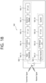
- FIG. 18 is a detailed block diagram illustrating the transceiver of the first device shown in FIG. 15 or the transceiver of the device shown in FIG. 17 in detail.
- the transceiver 1031 includes a transmitter 1031-1 and a receiver 1031-2.
- the transmitter 1031-1 includes a Discrete Fourier Transform (DFT) unit 1031-11, a subcarrier mapper 1031-12, an Inverse Fast Fourier Transform (IFFT) unit 1031-13 and a CP insertion unit 1031-14, and a radio transmitter 1031-15.
- the transmitter 1031-1 may further include a modulator.
- a scramble unit not shown
- a modulation mapper not shown
- a layer mapper not shown
- a layer permutator not shown
- the transmitter 1031-1 passes information through the DFT 1031-11 before mapping a signal to a subcarrier. After subcarrier mapping, by the subcarrier mapper 1031-12, of the signal spread (or precoded in the same sense) by the DFT unit 1031-11, a signal on the time axis is made through the IFFT unit 1031-13.
- PAPR Peak-to-Average Power Ratio
- the DFT unit 1031-11 outputs complex-valued symbols by performing DFT on input symbols. For example, when Ntx symbols are input (Ntx is a natural number), the DFT size is Ntx.
- the DFT unit 1031-11 may be referred to as a transform precoder.
- the subcarrier mapper 1031-12 maps the complex symbols to each subcarrier in the frequency domain. The complex symbols may be mapped to resource elements corresponding to resource blocks allocated for data transmission.
- the subcarrier mapper 1031-12 may be referred to as a resource element mapper.
- the IFFT unit 1031-13 outputs a baseband signal for data that is a time domain signal by performing IFFT on an input symbol.
- the CP insertion unit 1031-14 copies a part of the rear part of the baseband signal for data and inserts it in the front part of the baseband signal for data.
- ISI Inter-Symbol Interference
- ICI Inter-Carrier Interference
- the receiver 1031-2 includes a radio receiver 1031-21, a CP remover 1031-22, an FFT unit 1031-23, and an equalizer 1031-24, etc.
- the radio receiver 1031-21, the CP removing unit 1031-22, and the FFT unit 1031-23 of the receiver 1031-2 performs the reverse function of the radio transmitter 1031-15, the CP insertion unit 1031-14 and the IFFT unit 1031-13 of the transmitter 1031-1.
- the receiver 1031-2 may further include a demodulator.
- FIG. 19 illustrates a communication system 1 applied to the disclosure of the present specification.
- the communication system 1 applied to the disclosure of the present specification includes a wireless device, a base station, and a network.
- the wireless device refers to a device that performs communication using a radio access technology (e.g., 5G New RAT (NR)), Long-Term Evolution (LTE)), and may be referred to as a communication/wireless/5G device.
- NR 5G New RAT
- LTE Long-Term Evolution
- the wireless device may include a robot 100a, a vehicle 100b-1, 100b-2, an eXtended Reality (XR) device 100c, a hand-held device 100d, and a home appliance 100e, an Internet-of-Things (IoT) device 100f, and an AI device/server 400.
- a radio access technology e.g., 5G New RAT (NR)
- LTE Long-Term Evolution
- the wireless device may include a robot 100a, a vehicle 100b-1, 100b-2, an eXtended Reality (XR) device 100c,
- the vehicle may include a vehicle equipped with a wireless communication function, an autonomous driving vehicle, a vehicle capable of performing inter-vehicle communication, and the like.
- the vehicle may include an Unmanned Aerial Vehicle (UAV) (e.g., a drone).
- UAV Unmanned Aerial Vehicle
- XR devices include Augmented Reality (AR)/Virtual Reality (VR)/Mixed Reality (MR) devices, and may be implemented in the form of a Head-Mounted Device (HMD), a Head-Up Display (HUD) provided in a vehicle, a television, a smartphone, a computer, a wearable device, a home appliance, a digital signage, a vehicle, a robot, and the like.
- HMD Head-Mounted Device
- HUD Head-Up Display
- the hand-held device may include a smartphone, a smart pad, a wearable device (e.g., a smart watch, smart glasses), a computer (e.g., a laptop computer), and the like.
- Home appliances may include a TV, a refrigerator, a washing machine, and the like.
- the IoT device may include a sensor, a smart meter, and the like.
- the base station and the network may be implemented as a wireless device, and the specific wireless device 200a may operate as a base station/network node to other wireless devices.
- the wireless devices 100a to 100f may be connected to the network 300 via the base station 200.
- An Artificial Intelligence (AI) technology may be applied to the wireless devices 100a to 100f and the wireless devices 100a to 100f may be connected to the AI server 400 via the network 300.
- the network 300 may be configured using a 3G network, a 4G (e.g., LTE) network, a 5G (e.g., NR) network, and a beyond-5G network.
- the wireless devices 100a to 100f may communicate with each other through the base stations 200/network 300, the wireless devices 100a to 100f may perform direct communication (e.g., sidelink communication) with each other without passing through the BSs 200/network 300.
- the vehicles 100b-1 and 100b-2 may perform direct communication (e.g., Vehicle-to-Vehicle (V2V)/Vehicle-to-Everything (V2X) communication).
- the IoT device e.g., a sensor
- the IoT device may perform direct communication with other IoT devices (e.g., sensors) or other wireless devices 100a to 100f.
- the wireless communication/connections 150a, 150b and 150c may transmit/receive signals through various physical channels.
- various configuration information configuring processes e.g., channel encoding/decoding, modulation/demodulation, and resource mapping/de-mapping
- resource allocating processes for transmitting/receiving radio signals, may be performed based on the various proposals of the present disclosure.
Landscapes
- Engineering & Computer Science (AREA)
- Computer Networks & Wireless Communication (AREA)
- Signal Processing (AREA)
- Mobile Radio Communication Systems (AREA)
Claims (13)
- Verfahren zum Betreiben einer Sitzungsmanagementfunktion, SMF, wobei das Verfahren umfasst:Empfangen, von einer Zugriffs- und Mobilitätsmanagementfunktion, AMF, einer Anforderungsnachricht für den Aufbau einer Protokolldateneinheit-, PDU-, Sitzung auf der Grundlage eines Handovers einer PDU-Sitzung zwischen einem Nicht-3rd Generation Partnership Project-, Nicht-3GPP-, Zugriff und einem 3GPP-Zugriff;Übertragen, an die AMF, einer Sitzungsmanagement-, SM-, Kontextstatus-Benachrichtigungsnachricht, auf der Grundlage, dass der Aufbau der PDU-Sitzung fehlgeschlagen ist,wobei die SM-Kontextstatus-Benachrichtigungsnachricht die AMF in die Lage versetzt, einen auf die PDU-Sitzung bezogenen Zugriffstyp auf der Grundlage der SM-Kontextstatus-Benachrichtigungsnachricht zu aktualisieren.
- Verfahren nach Anspruch 1,
wobei die Anforderungsnachricht einen auf "Existierende PDU-Sitzung" eingestellten Anforderungstyp enthält. - Verfahren nach Anspruch 1,
wobei die SM-Kontextstatus-Benachrichtigungsnachricht Informationen über den Zugangstyp für die PDU-Sitzung nach einem Fehlschlag des Handovers enthält. - Verfahren nach Anspruch 3,
wobei der Zugriffstyp auf der Grundlage der in der SM-Kontextstatus-Benachrichtigungsnachricht enthaltenen Informationen über den Zugriffstyp aktualisiert wird. - Verfahren nach Anspruch 3,
wobei die Information über den Zugriffstyp für die PDU-Sitzung den Nicht-3GPP-Zugriff angibt, basierend auf dem Fehlschlag des Handovers der PDU-Sitzung zwischen dem Nicht-3GPP-Zugriff und dem 3GPP-Zugriff. - Verfahren nach Anspruch 3,
wobei der Zugriffstyp, der sich auf die PDU-Sitzung bezieht, auf der Grundlage des fehlgeschlagenen Handovers der PDU-Sitzung zwischen dem Nicht-3GPP-Zugriff und dem 3GPP-Zugriff auf den Nicht-3GPP-Zugriff aktualisiert wird. - Verfahren nach Anspruch 3,
wobei der Fehlschlag des Aufbaus der PDU-Sitzungsprozedur auf einem Fehlschlag des Ressourcenaufbaus eines Zugriffsnetzwerks, AN, beruht. - Sitzungsmanagementfunktion, SMF, zur Durchführung einer Kommunikation, umfassend:einen Transceiver (1031a);mindestens einen Prozessor (1020a); undmindestens einen Speicher (1010a) zum Speichern von Befehlen, der mit dem mindestens einen Prozessor (1020a) elektrisch verbunden werden kann,wobei die Befehle, basierend auf der Ausführung durch den mindestens einen Prozessor (1020a), Operationen durchführen, die Folgendes umfassen:Empfangen, von einer Zugriffs- und Mobilitätsmanagementfunktion, AMF, einer Anforderungsnachricht für den Aufbau einer Protokolldateneinheit-, PDU-, Sitzung auf der Grundlage eines Handovers einer PDU-Sitzung zwischen einem Nicht-3rd Generation Partnership Project-, Nicht-3GPP-, Zugriff und einem 3GPP-Zugriff;Übertragen, an die AMF, einer Sitzungsmanagement-, SM-, Kontextstatus-Benachrichtigungsnachricht, auf der Grundlage, dass der Aufbau der PDU-Sitzung fehlgeschlagen ist,wobei die SM-Kontextstatus-Benachrichtigungsnachricht die AMF in die Lage versetzt, einen auf die PDU-Sitzung bezogenen Zugriffstyp auf der Grundlage der SM-Kontextstatus-Benachrichtigungsnachricht zu aktualisieren.
- SMF nach Anspruch 8,
wobei die Anforderungsnachricht einen auf "Existierende PDU-Sitzung" eingestellten Anforderungstyp enthält. - SMF nach Anspruch 8,
wobei die SM-Kontextstatus-Benachrichtigungsnachricht Informationen über den Zugangstyp für die PDU-Sitzung nach einem Fehlschlag des Handovers enthält. - SMF nach Anspruch 8,
wobei der Zugriffstyp auf der Grundlage der in der SM-Kontextstatus-Benachrichtigungsnachricht enthaltenen Informationen über den Zugriffstyp aktualisiert wird. - SMF nach Anspruch 8,
wobei die Information über den Zugriffstyp für die PDU-Sitzung den Nicht-3GPP-Zugriff angibt, basierend auf dem Fehlschlag des Handovers der PDU-Sitzung zwischen dem Nicht-3GPP-Zugriff und dem 3GPP-Zugriff. - SMF nach Anspruch 8,
wobei der Zugriffstyp, der sich auf die PDU-Sitzung bezieht, auf der Grundlage des fehlgeschlagenen Handovers der PDU-Sitzung zwischen dem Nicht-3GPP-Zugriff und dem 3GPP-Zugriff auf den Nicht-3GPP-Zugriff aktualisiert wird.
Applications Claiming Priority (3)
| Application Number | Priority Date | Filing Date | Title |
|---|---|---|---|
| KR20190122515 | 2019-10-02 | ||
| EP20871265.3A EP4021075B1 (de) | 2019-10-02 | 2020-09-11 | Verfahren zum verschieben einer pdu-sitzung von einem nicht-3gpp- zu einem 3gpp-zugang |
| PCT/KR2020/012309 WO2021066346A1 (ko) | 2019-10-02 | 2020-09-11 | 비-3gpp 상의 pdu 세션을 3gpp 액세스로 이동시키기 위한 방안 |
Related Parent Applications (1)
| Application Number | Title | Priority Date | Filing Date |
|---|---|---|---|
| EP20871265.3A Division EP4021075B1 (de) | 2019-10-02 | 2020-09-11 | Verfahren zum verschieben einer pdu-sitzung von einem nicht-3gpp- zu einem 3gpp-zugang |
Publications (2)
| Publication Number | Publication Date |
|---|---|
| EP4329367A1 EP4329367A1 (de) | 2024-02-28 |
| EP4329367B1 true EP4329367B1 (de) | 2025-04-16 |
Family
ID=75337185
Family Applications (2)
| Application Number | Title | Priority Date | Filing Date |
|---|---|---|---|
| EP20871265.3A Active EP4021075B1 (de) | 2019-10-02 | 2020-09-11 | Verfahren zum verschieben einer pdu-sitzung von einem nicht-3gpp- zu einem 3gpp-zugang |
| EP23204349.7A Active EP4329367B1 (de) | 2019-10-02 | 2020-09-11 | Verfahren zum verschieben einer pdu-sitzung von einem nicht-3gpp- zu einem 3gpp-zugang |
Family Applications Before (1)
| Application Number | Title | Priority Date | Filing Date |
|---|---|---|---|
| EP20871265.3A Active EP4021075B1 (de) | 2019-10-02 | 2020-09-11 | Verfahren zum verschieben einer pdu-sitzung von einem nicht-3gpp- zu einem 3gpp-zugang |
Country Status (5)
| Country | Link |
|---|---|
| US (1) | US12120558B2 (de) |
| EP (2) | EP4021075B1 (de) |
| KR (1) | KR102719658B1 (de) |
| CN (1) | CN114557031B (de) |
| WO (1) | WO2021066346A1 (de) |
Families Citing this family (9)
| Publication number | Priority date | Publication date | Assignee | Title |
|---|---|---|---|---|
| EP4197228A1 (de) * | 2020-08-12 | 2023-06-21 | InterDigital Patent Holdings, Inc. | Umpositionierung eines edge-anwendungsservers |
| EP4324245A4 (de) | 2021-04-14 | 2025-03-05 | Telefonaktiebolaget LM Ericsson (publ) | Verfahren und vorrichtung zur neuauswahl einer sitzungsverwaltungsfunktion |
| WO2023174542A1 (en) * | 2022-03-17 | 2023-09-21 | Nokia Solutions And Networks Oy | Enabling direct service-based requests from radio access network nodes towards 5g core network functions |
| CN117158033A (zh) * | 2022-03-29 | 2023-12-01 | 北京小米移动软件有限公司 | 基于增强现实业务的会话管理功能选择方法及装置、存储介质 |
| US12407537B2 (en) * | 2022-09-17 | 2025-09-02 | Radisys Corporation | NR-NR dual connectivity (NR-DC) secondary node (SN) data usage reporting |
| WO2024098632A1 (en) * | 2023-03-30 | 2024-05-16 | Zte Corporation | Systems and methods for determining network capability via control plane |
| CN118785524A (zh) * | 2023-04-07 | 2024-10-15 | 华为技术有限公司 | 通信方法及装置 |
| WO2025008977A1 (en) * | 2023-07-05 | 2025-01-09 | Jio Platforms Limited | Method and system for handling initial context setup failure message |
| WO2024109127A1 (en) * | 2023-07-21 | 2024-05-30 | Zte Corporation | System and methods for flow mobility control |
Family Cites Families (10)
| Publication number | Priority date | Publication date | Assignee | Title |
|---|---|---|---|---|
| CN101646248B (zh) * | 2008-08-07 | 2011-11-02 | 华为技术有限公司 | 封闭用户组信息处理方法、接入控制方法及系统和设备 |
| KR102201279B1 (ko) | 2016-11-27 | 2021-01-11 | 엘지전자 주식회사 | 무선 통신 시스템에서의 등록 해제 방법 및 이를 위한 장치 |
| ES2929669T3 (es) * | 2017-01-09 | 2022-11-30 | Lg Electronics Inc | Método para el interfuncionamiento entre redes en un sistema de comunicación inalámbrica y aparatos para el mismo |
| RU2727184C1 (ru) * | 2017-04-19 | 2020-07-21 | ЭлДжи ЭЛЕКТРОНИКС ИНК. | Способ обработки процедуры установления сеанса связи pdu и узел amf |
| KR102026950B1 (ko) * | 2017-04-19 | 2019-09-30 | 엘지전자 주식회사 | Pdu 세션 수립 절차를 처리하는 방법 및 amf 노드 |
| KR102336313B1 (ko) * | 2017-06-19 | 2021-12-07 | 삼성전자 주식회사 | 네트워크 가상화 및 세션 관리 방법 및 장치 |
| CN109219092B (zh) * | 2017-06-30 | 2021-01-26 | 展讯通信(上海)有限公司 | 从非3gpp接入网切换到3gpp接入网的方法、装置及终端 |
| US10999787B2 (en) | 2018-02-17 | 2021-05-04 | Huawei Technologies Co., Ltd. | System and method for UE context and PDU session context management |
| CN110830928B (zh) * | 2018-08-13 | 2021-09-03 | 华为技术有限公司 | 通信方法和装置 |
| US11419174B2 (en) * | 2019-02-26 | 2022-08-16 | Mediatek Inc. | Connection recovery method for recovering a connection between a communications apparatus and a data network and the associated communications apparatus |
-
2020
- 2020-09-11 KR KR1020227011129A patent/KR102719658B1/ko active Active
- 2020-09-11 US US17/642,899 patent/US12120558B2/en active Active
- 2020-09-11 WO PCT/KR2020/012309 patent/WO2021066346A1/ko not_active Ceased
- 2020-09-11 EP EP20871265.3A patent/EP4021075B1/de active Active
- 2020-09-11 CN CN202080070157.5A patent/CN114557031B/zh active Active
- 2020-09-11 EP EP23204349.7A patent/EP4329367B1/de active Active
Also Published As
| Publication number | Publication date |
|---|---|
| US12120558B2 (en) | 2024-10-15 |
| US20220361054A1 (en) | 2022-11-10 |
| CN114557031B (zh) | 2023-06-09 |
| WO2021066346A1 (ko) | 2021-04-08 |
| CN114557031A (zh) | 2022-05-27 |
| EP4021075A4 (de) | 2022-10-12 |
| EP4021075B1 (de) | 2023-11-01 |
| EP4329367A1 (de) | 2024-02-28 |
| KR102719658B1 (ko) | 2024-10-21 |
| KR20220061156A (ko) | 2022-05-12 |
| EP4021075A1 (de) | 2022-06-29 |
Similar Documents
| Publication | Publication Date | Title |
|---|---|---|
| EP4021073B1 (de) | Verfahren zum verschieben einer ims-sprachsitzung von einem nicht-3gpp- zu einem 3gpp-zugang | |
| US12200595B2 (en) | Path-switching between PC5 link and UU link | |
| EP4329367B1 (de) | Verfahren zum verschieben einer pdu-sitzung von einem nicht-3gpp- zu einem 3gpp-zugang | |
| EP3989675A1 (de) | Verfahren zur weiterleitung von unstrukturiertem verkehr und relais-benutzergerät | |
| US12219626B2 (en) | Communication related to 3GPP PS data off | |
| US12309736B2 (en) | Communication related to multiple usims | |
| EP4167620B1 (de) | Verfahren zur auslösung von smf zur effektiven durchführung einer redundanten übertragung durch verbesserung der funktion von nwdaf | |
| EP4021138B1 (de) | Behandlung einer empfangenen rrc-verbindungsrekonfigurationsnachricht durch ein relais-ue | |
| US12177762B2 (en) | Method for accessing NPN in 5G mobile communication system, and user equipment | |
| EP4156753B1 (de) | Verfahren zum betreiben von smf unter verwendung von analyseinformationen von nwdaf | |
| US20230189208A1 (en) | Processing method of amf for supporting multiple usims | |
| US12150044B2 (en) | Scheme for selecting SMF node | |
| US12231879B2 (en) | Operating method for AUSF and UDM for authentication and authorization for each network slice | |
| EP4109975A1 (de) | Kommunikation in bezug auf netzwerkslice | |
| US20230189268A1 (en) | Operating method for user equipment supporting multiple usim |
Legal Events
| Date | Code | Title | Description |
|---|---|---|---|
| PUAI | Public reference made under article 153(3) epc to a published international application that has entered the european phase |
Free format text: ORIGINAL CODE: 0009012 |
|
| STAA | Information on the status of an ep patent application or granted ep patent |
Free format text: STATUS: REQUEST FOR EXAMINATION WAS MADE |
|
| 17P | Request for examination filed |
Effective date: 20231018 |
|
| AC | Divisional application: reference to earlier application |
Ref document number: 4021075 Country of ref document: EP Kind code of ref document: P |
|
| AK | Designated contracting states |
Kind code of ref document: A1 Designated state(s): AL AT BE BG CH CY CZ DE DK EE ES FI FR GB GR HR HU IE IS IT LI LT LU LV MC MK MT NL NO PL PT RO RS SE SI SK SM TR |
|
| GRAP | Despatch of communication of intention to grant a patent |
Free format text: ORIGINAL CODE: EPIDOSNIGR1 |
|
| STAA | Information on the status of an ep patent application or granted ep patent |
Free format text: STATUS: GRANT OF PATENT IS INTENDED |
|
| RIC1 | Information provided on ipc code assigned before grant |
Ipc: H04W 76/12 20180101ALN20241028BHEP Ipc: H04W 36/32 20090101ALN20241028BHEP Ipc: H04W 36/14 20090101ALN20241028BHEP Ipc: H04W 36/12 20090101ALN20241028BHEP Ipc: H04W 76/18 20180101ALI20241028BHEP Ipc: H04W 36/00 20090101AFI20241028BHEP |
|
| INTG | Intention to grant announced |
Effective date: 20241119 |
|
| GRAS | Grant fee paid |
Free format text: ORIGINAL CODE: EPIDOSNIGR3 |
|
| GRAA | (expected) grant |
Free format text: ORIGINAL CODE: 0009210 |
|
| STAA | Information on the status of an ep patent application or granted ep patent |
Free format text: STATUS: THE PATENT HAS BEEN GRANTED |
|
| AC | Divisional application: reference to earlier application |
Ref document number: 4021075 Country of ref document: EP Kind code of ref document: P |
|
| AK | Designated contracting states |
Kind code of ref document: B1 Designated state(s): AL AT BE BG CH CY CZ DE DK EE ES FI FR GB GR HR HU IE IS IT LI LT LU LV MC MK MT NL NO PL PT RO RS SE SI SK SM TR |
|
| REG | Reference to a national code |
Ref country code: GB Ref legal event code: FG4D |
|
| REG | Reference to a national code |
Ref country code: CH Ref legal event code: EP |
|
| REG | Reference to a national code |
Ref country code: IE Ref legal event code: FG4D |
|
| REG | Reference to a national code |
Ref country code: DE Ref legal event code: R096 Ref document number: 602020049789 Country of ref document: DE |
|
| REG | Reference to a national code |
Ref country code: NL Ref legal event code: MP Effective date: 20250416 |
|
| PG25 | Lapsed in a contracting state [announced via postgrant information from national office to epo] |
Ref country code: NL Free format text: LAPSE BECAUSE OF FAILURE TO SUBMIT A TRANSLATION OF THE DESCRIPTION OR TO PAY THE FEE WITHIN THE PRESCRIBED TIME-LIMIT Effective date: 20250416 |
|
| REG | Reference to a national code |
Ref country code: AT Ref legal event code: MK05 Ref document number: 1786709 Country of ref document: AT Kind code of ref document: T Effective date: 20250416 |
|
| PG25 | Lapsed in a contracting state [announced via postgrant information from national office to epo] |
Ref country code: PT Free format text: LAPSE BECAUSE OF FAILURE TO SUBMIT A TRANSLATION OF THE DESCRIPTION OR TO PAY THE FEE WITHIN THE PRESCRIBED TIME-LIMIT Effective date: 20250818 Ref country code: FI Free format text: LAPSE BECAUSE OF FAILURE TO SUBMIT A TRANSLATION OF THE DESCRIPTION OR TO PAY THE FEE WITHIN THE PRESCRIBED TIME-LIMIT Effective date: 20250416 Ref country code: ES Free format text: LAPSE BECAUSE OF FAILURE TO SUBMIT A TRANSLATION OF THE DESCRIPTION OR TO PAY THE FEE WITHIN THE PRESCRIBED TIME-LIMIT Effective date: 20250416 |
|
| PGFP | Annual fee paid to national office [announced via postgrant information from national office to epo] |
Ref country code: DE Payment date: 20250805 Year of fee payment: 6 |
|
| REG | Reference to a national code |
Ref country code: LT Ref legal event code: MG9D |
|
| PG25 | Lapsed in a contracting state [announced via postgrant information from national office to epo] |
Ref country code: GR Free format text: LAPSE BECAUSE OF FAILURE TO SUBMIT A TRANSLATION OF THE DESCRIPTION OR TO PAY THE FEE WITHIN THE PRESCRIBED TIME-LIMIT Effective date: 20250717 Ref country code: NO Free format text: LAPSE BECAUSE OF FAILURE TO SUBMIT A TRANSLATION OF THE DESCRIPTION OR TO PAY THE FEE WITHIN THE PRESCRIBED TIME-LIMIT Effective date: 20250716 |
|
| PG25 | Lapsed in a contracting state [announced via postgrant information from national office to epo] |
Ref country code: PL Free format text: LAPSE BECAUSE OF FAILURE TO SUBMIT A TRANSLATION OF THE DESCRIPTION OR TO PAY THE FEE WITHIN THE PRESCRIBED TIME-LIMIT Effective date: 20250416 |
|
| PG25 | Lapsed in a contracting state [announced via postgrant information from national office to epo] |
Ref country code: BG Free format text: LAPSE BECAUSE OF FAILURE TO SUBMIT A TRANSLATION OF THE DESCRIPTION OR TO PAY THE FEE WITHIN THE PRESCRIBED TIME-LIMIT Effective date: 20250416 |
|
| PGFP | Annual fee paid to national office [announced via postgrant information from national office to epo] |
Ref country code: GB Payment date: 20250805 Year of fee payment: 6 |
|
| PG25 | Lapsed in a contracting state [announced via postgrant information from national office to epo] |
Ref country code: HR Free format text: LAPSE BECAUSE OF FAILURE TO SUBMIT A TRANSLATION OF THE DESCRIPTION OR TO PAY THE FEE WITHIN THE PRESCRIBED TIME-LIMIT Effective date: 20250416 |
|
| PG25 | Lapsed in a contracting state [announced via postgrant information from national office to epo] |
Ref country code: AT Free format text: LAPSE BECAUSE OF FAILURE TO SUBMIT A TRANSLATION OF THE DESCRIPTION OR TO PAY THE FEE WITHIN THE PRESCRIBED TIME-LIMIT Effective date: 20250416 |
|
| PGFP | Annual fee paid to national office [announced via postgrant information from national office to epo] |
Ref country code: FR Payment date: 20250807 Year of fee payment: 6 |
|
| PG25 | Lapsed in a contracting state [announced via postgrant information from national office to epo] |
Ref country code: RS Free format text: LAPSE BECAUSE OF FAILURE TO SUBMIT A TRANSLATION OF THE DESCRIPTION OR TO PAY THE FEE WITHIN THE PRESCRIBED TIME-LIMIT Effective date: 20250716 |
|
| PG25 | Lapsed in a contracting state [announced via postgrant information from national office to epo] |
Ref country code: IS Free format text: LAPSE BECAUSE OF FAILURE TO SUBMIT A TRANSLATION OF THE DESCRIPTION OR TO PAY THE FEE WITHIN THE PRESCRIBED TIME-LIMIT Effective date: 20250816 |
|
| PG25 | Lapsed in a contracting state [announced via postgrant information from national office to epo] |
Ref country code: LV Free format text: LAPSE BECAUSE OF FAILURE TO SUBMIT A TRANSLATION OF THE DESCRIPTION OR TO PAY THE FEE WITHIN THE PRESCRIBED TIME-LIMIT Effective date: 20250416 |
|
| PG25 | Lapsed in a contracting state [announced via postgrant information from national office to epo] |
Ref country code: SM Free format text: LAPSE BECAUSE OF FAILURE TO SUBMIT A TRANSLATION OF THE DESCRIPTION OR TO PAY THE FEE WITHIN THE PRESCRIBED TIME-LIMIT Effective date: 20250416 Ref country code: DK Free format text: LAPSE BECAUSE OF FAILURE TO SUBMIT A TRANSLATION OF THE DESCRIPTION OR TO PAY THE FEE WITHIN THE PRESCRIBED TIME-LIMIT Effective date: 20250416 |
|
| PG25 | Lapsed in a contracting state [announced via postgrant information from national office to epo] |
Ref country code: CZ Free format text: LAPSE BECAUSE OF FAILURE TO SUBMIT A TRANSLATION OF THE DESCRIPTION OR TO PAY THE FEE WITHIN THE PRESCRIBED TIME-LIMIT Effective date: 20250416 |
|
| PG25 | Lapsed in a contracting state [announced via postgrant information from national office to epo] |
Ref country code: EE Free format text: LAPSE BECAUSE OF FAILURE TO SUBMIT A TRANSLATION OF THE DESCRIPTION OR TO PAY THE FEE WITHIN THE PRESCRIBED TIME-LIMIT Effective date: 20250416 |
|
| PG25 | Lapsed in a contracting state [announced via postgrant information from national office to epo] |
Ref country code: SK Free format text: LAPSE BECAUSE OF FAILURE TO SUBMIT A TRANSLATION OF THE DESCRIPTION OR TO PAY THE FEE WITHIN THE PRESCRIBED TIME-LIMIT Effective date: 20250416 |
|
| PG25 | Lapsed in a contracting state [announced via postgrant information from national office to epo] |
Ref country code: IT Free format text: LAPSE BECAUSE OF FAILURE TO SUBMIT A TRANSLATION OF THE DESCRIPTION OR TO PAY THE FEE WITHIN THE PRESCRIBED TIME-LIMIT Effective date: 20250416 |