EP4329263B1 - Verfahren und system zur automatischen abstimmung eines umschaltzeitgebers in netzwerksystemen oder notfallsystemen der nächsten generation - Google Patents
Verfahren und system zur automatischen abstimmung eines umschaltzeitgebers in netzwerksystemen oder notfallsystemen der nächsten generation Download PDFInfo
- Publication number
- EP4329263B1 EP4329263B1 EP22191989.7A EP22191989A EP4329263B1 EP 4329263 B1 EP4329263 B1 EP 4329263B1 EP 22191989 A EP22191989 A EP 22191989A EP 4329263 B1 EP4329263 B1 EP 4329263B1
- Authority
- EP
- European Patent Office
- Prior art keywords
- network
- master node
- switchover
- heartbeat
- node
- Prior art date
- Legal status (The legal status is an assumption and is not a legal conclusion. Google has not performed a legal analysis and makes no representation as to the accuracy of the status listed.)
- Active
Links
Images
Classifications
-
- H—ELECTRICITY
- H04—ELECTRIC COMMUNICATION TECHNIQUE
- H04L—TRANSMISSION OF DIGITAL INFORMATION, e.g. TELEGRAPHIC COMMUNICATION
- H04L65/00—Network arrangements, protocols or services for supporting real-time applications in data packet communication
- H04L65/1066—Session management
- H04L65/1101—Session protocols
- H04L65/1104—Session initiation protocol [SIP]
-
- G—PHYSICS
- G06—COMPUTING OR CALCULATING; COUNTING
- G06F—ELECTRIC DIGITAL DATA PROCESSING
- G06F11/00—Error detection; Error correction; Monitoring
- G06F11/07—Responding to the occurrence of a fault, e.g. fault tolerance
- G06F11/0703—Error or fault processing not based on redundancy, i.e. by taking additional measures to deal with the error or fault not making use of redundancy in operation, in hardware, or in data representation
- G06F11/0706—Error or fault processing not based on redundancy, i.e. by taking additional measures to deal with the error or fault not making use of redundancy in operation, in hardware, or in data representation the processing taking place on a specific hardware platform or in a specific software environment
- G06F11/0709—Error or fault processing not based on redundancy, i.e. by taking additional measures to deal with the error or fault not making use of redundancy in operation, in hardware, or in data representation the processing taking place on a specific hardware platform or in a specific software environment in a distributed system consisting of a plurality of standalone computer nodes, e.g. clusters, client-server systems
-
- G—PHYSICS
- G06—COMPUTING OR CALCULATING; COUNTING
- G06F—ELECTRIC DIGITAL DATA PROCESSING
- G06F11/00—Error detection; Error correction; Monitoring
- G06F11/07—Responding to the occurrence of a fault, e.g. fault tolerance
- G06F11/0703—Error or fault processing not based on redundancy, i.e. by taking additional measures to deal with the error or fault not making use of redundancy in operation, in hardware, or in data representation
- G06F11/0751—Error or fault detection not based on redundancy
- G06F11/0754—Error or fault detection not based on redundancy by exceeding limits
- G06F11/0757—Error or fault detection not based on redundancy by exceeding limits by exceeding a time limit, i.e. time-out, e.g. watchdogs
-
- G—PHYSICS
- G06—COMPUTING OR CALCULATING; COUNTING
- G06F—ELECTRIC DIGITAL DATA PROCESSING
- G06F11/00—Error detection; Error correction; Monitoring
- G06F11/07—Responding to the occurrence of a fault, e.g. fault tolerance
- G06F11/16—Error detection or correction of the data by redundancy in hardware
- G06F11/20—Error detection or correction of the data by redundancy in hardware using active fault-masking, e.g. by switching out faulty elements or by switching in spare elements
- G06F11/202—Error detection or correction of the data by redundancy in hardware using active fault-masking, e.g. by switching out faulty elements or by switching in spare elements where processing functionality is redundant
- G06F11/2023—Failover techniques
- G06F11/2025—Failover techniques using centralised failover control functionality
-
- G—PHYSICS
- G06—COMPUTING OR CALCULATING; COUNTING
- G06F—ELECTRIC DIGITAL DATA PROCESSING
- G06F11/00—Error detection; Error correction; Monitoring
- G06F11/07—Responding to the occurrence of a fault, e.g. fault tolerance
- G06F11/16—Error detection or correction of the data by redundancy in hardware
- G06F11/20—Error detection or correction of the data by redundancy in hardware using active fault-masking, e.g. by switching out faulty elements or by switching in spare elements
- G06F11/202—Error detection or correction of the data by redundancy in hardware using active fault-masking, e.g. by switching out faulty elements or by switching in spare elements where processing functionality is redundant
- G06F11/2023—Failover techniques
- G06F11/2028—Failover techniques eliminating a faulty processor or activating a spare
-
- H—ELECTRICITY
- H04—ELECTRIC COMMUNICATION TECHNIQUE
- H04L—TRANSMISSION OF DIGITAL INFORMATION, e.g. TELEGRAPHIC COMMUNICATION
- H04L41/00—Arrangements for maintenance, administration or management of data switching networks, e.g. of packet switching networks
- H04L41/06—Management of faults, events, alarms or notifications
- H04L41/0654—Management of faults, events, alarms or notifications using network fault recovery
- H04L41/0663—Performing the actions predefined by failover planning, e.g. switching to standby network elements
-
- H—ELECTRICITY
- H04—ELECTRIC COMMUNICATION TECHNIQUE
- H04L—TRANSMISSION OF DIGITAL INFORMATION, e.g. TELEGRAPHIC COMMUNICATION
- H04L43/00—Arrangements for monitoring or testing data switching networks
- H04L43/10—Active monitoring, e.g. heartbeat, ping or trace-route
-
- H—ELECTRICITY
- H04—ELECTRIC COMMUNICATION TECHNIQUE
- H04L—TRANSMISSION OF DIGITAL INFORMATION, e.g. TELEGRAPHIC COMMUNICATION
- H04L67/00—Network arrangements or protocols for supporting network services or applications
- H04L67/01—Protocols
- H04L67/10—Protocols in which an application is distributed across nodes in the network
- H04L67/1001—Protocols in which an application is distributed across nodes in the network for accessing one among a plurality of replicated servers
-
- H—ELECTRICITY
- H04—ELECTRIC COMMUNICATION TECHNIQUE
- H04L—TRANSMISSION OF DIGITAL INFORMATION, e.g. TELEGRAPHIC COMMUNICATION
- H04L69/00—Network arrangements, protocols or services independent of the application payload and not provided for in the other groups of this subclass
- H04L69/28—Timers or timing mechanisms used in protocols
-
- H—ELECTRICITY
- H04—ELECTRIC COMMUNICATION TECHNIQUE
- H04L—TRANSMISSION OF DIGITAL INFORMATION, e.g. TELEGRAPHIC COMMUNICATION
- H04L69/00—Network arrangements, protocols or services independent of the application payload and not provided for in the other groups of this subclass
- H04L69/40—Network arrangements, protocols or services independent of the application payload and not provided for in the other groups of this subclass for recovering from a failure of a protocol instance or entity, e.g. service redundancy protocols, protocol state redundancy or protocol service redirection
-
- H—ELECTRICITY
- H04—ELECTRIC COMMUNICATION TECHNIQUE
- H04L—TRANSMISSION OF DIGITAL INFORMATION, e.g. TELEGRAPHIC COMMUNICATION
- H04L43/00—Arrangements for monitoring or testing data switching networks
- H04L43/08—Monitoring or testing based on specific metrics, e.g. QoS, energy consumption or environmental parameters
- H04L43/0805—Monitoring or testing based on specific metrics, e.g. QoS, energy consumption or environmental parameters by checking availability
- H04L43/0817—Monitoring or testing based on specific metrics, e.g. QoS, energy consumption or environmental parameters by checking availability by checking functioning
Definitions
- the present invention relates to a method and a system for automated switchover timer tuning on network systems or Next Generation Emergency Systems.
- Switchover is the manual switch from one system to a redundant or standby computer server, system, or network upon the failure or abnormal termination of the previously active server, system, or network, or to perform system maintenance, such as installing patches, and upgrading software or hardware.
- the automatic switchover of a redundant system in the event of an error condition without human intervention is called failover.
- the manual switchover in case of an error would be used if an automatic failover is not available, possibly because the overall system is too complex.
- the switchover time is very critical on some network systems like Next Generation Emergency systems (NG911/NG112, wherein 911 is primarily used in North America and 112 is primarily used in Europe). Different from an enterprise environment network system, the switchover time in a redundant system like in a Next Generation Emergency System needs to be much shorter, limited to a very few seconds only.
- the Border Control Function provides a secure entry into the Emergency Services IP Network (ESlnet) for emergency calls presented to the network.
- the BCF incorporates a firewall, admission control, and may include anchoring of session and media as well as other security mechanisms to prevent deliberate or malicious attacks on Public Safety Answering Points (PSAPs) or other entities connected to the ESInet.
- PSAPs Public Safety Answering Points
- the ESlnet is a managed IP network that is used for emergency services communications, and which can be shared by all public safety agencies. It provides the IP (Internet Protocol) transport infrastructure upon which independent application platforms and core services can be deployed, including, but not restricted to, those necessary for providing NG911/NG112 services.
- ESInets may be constructed from a mix of dedicated and shared facilities. ESInets may be interconnected at local, regional, state, federal, national and international levels to form an IP-based inter-network (network of networks). The term ESInet designates the network, not the services that run on the network.
- NENA National Emergency Number Association
- EENA European Emergency Number Association
- the timers in the switchover mechanism from the BCF system were adjusted to the minimum value possible.
- multiple performance tests were executed, e. g. in the Boca Raton, or the California Governor's Office of Emergency Services (Cal OES) Project Staging Laboratory.
- Split-brain is a computer term, based on an analogy with the medical Split-brain syndrome. It indicates data or availability inconsistencies originating from the maintenance of two separate data sets with overlap in scope, either because of servers in a network design, or a failure condition based on servers not communicating and synchronizing their data to each other. This last case is also commonly referred to as a network partition.
- the split-brain problem was solved after increasing the ARP timers manually on both the master and the backup system. After that, some improvements in the redundancy mechanism were implemented to provide a faster switchover process. At this point, the problem seemed to be solved although this had the consequence of the switchover time increased to 5 seconds (on the average).
- server failover clustering is a high availability platform that is constantly monitoring the network connections and health of the nodes in a cluster. If a node is not reachable over the network, then recovery actions are taken to recover and bring applications and services online on another node in the cluster. These default settings deliver the best behavior for most customers, however, as clusters are stretched from being inches to possibly miles apart, the cluster may become exposed to additional and potentially unreliable networking components between the nodes. Another factor is that the quality of commodity servers is constantly increasing, coupled with augmented resiliency through redundant components (such as dual power supplies, Network Information Center (NIC) teaming, and multi-path I/O), the number of non-redundant hardware failures may potentially be fairly rare.
- NIC Network Information Center
- a heartbeat is a periodic signal generated by a hardware or software to indicate normal operation or to synchronize other parts of a computer system.
- Heartbeat mechanism is one of the common techniques in mission critical systems for providing high availability and fault tolerance of network services by detecting the network or systems failures of nodes or daemons which belong to a network cluster - administered by a master server - for the purpose of automatic adaptation and rebalancing of the system by using the remaining redundant nodes on the cluster to take over the load of failed nodes for providing constant services.
- a heartbeat is sent between machines at a regular interval in the order of seconds, a heartbeat message.
- Heartbeat messages are typically sent non-stop on a periodic or recurring basis from the originator's start-up until the originator's shutdown.
- the destination may determine that the originator has failed, shutdown, or is generally no longer available.
- US 20120124431 A1 describes a method and system for client recovery strategy in a redundant server configuration. It is desirable to use small values for parameters to detect failures and failover to an alternate server as quickly as possible, minimizing downtime and failed requests.
- failing over to an alternate server uses resources on that server to register the client and to retrieve the context information for that client. If too many clients failover simultaneously, an excessive number of registration attempts may drive the alternate server into an overload. Therefore, it may be advantageous to avoid failovers for minor transient failures (such as blade failovers or temporarily slow processes due to a burst of traffic). Further, the failure detection time is improved by collecting historical data on response times and the number of retries necessary for a successful response.
- TIMEOUT and/or the maximum number of retries can be adaptively adjusted to detect faults and trigger a recovery, as compared to the standard protocol timeout, and retry strategy more rapidly.
- collecting the data and adaptively adjusting the timing parameters may be accomplished using a variety of techniques.
- the data or response times and/or the number of retries are tracked or maintained (e. g. by the client) for a predetermined period, e. g. daily.
- the tracked data may be used to make the adaptive or dynamic adjustment. For example, it may be determined (e. g. by the client) that the adjusted value for the timer is set at a certain percentage (e. g.
- the values may be updated periodically, e. g. every 15 minutes, every 100 packets, etc., to suit the needs of the network.
- This historical data may also be used to implement adjustments based on predictive behavior. In this described method, all failure handling is for the server, that is, the server-side will adjust the timers according to the response of some tests.
- the present invention is based on the object to provide a method and a corresponding system for automated switchover timer tuning on network systems or Next Generation Emergency Systems.
- a method and a system for automated switchover timer tuning which generate a 4 second maximum silence/unattended call duration on NG911/NG112 systems during a switchover.
- a node in sense of the invention is defined as one of the redundancy server elements. This can be usually the master or slave in a network.
- a backup server in sense of the invention is defined as a server in a stand-by mode and is used to take over the mastership in case of a master node problem.
- a method for automated switchover timer tuning on network systems or Next Generation Emergency Systems comprising the steps S1) sending, by a master node, a heartbeat and/or ARP ping to one or more backup nodes and/or a surveillance unit according to preconfigured switchover timer values to check if the master node is still active.
- S2 sending, by the one or more backup node and/or the surveillance unit, an additional first Session Initiation Protocol, SIP, OPTION message to the master node after receiving the heartbeat and/or the ARP ping or if the heartbeat and/or ARP ping fails to be received according to the switchover timer values.
- SIP Session Initiation Protocol
- the method further comprises after sending, by the one or more backup node and/or the surveillance unit, the additional first Session Initiation Protocol, SIP, OPTION message to the master node further comprising, S4) recalibrating and decreasing, by the master node, the switchover timer values by sending a second SIP OPTION message comprising a new header indicating the altered switchover timer values, in case the heartbeat and/or the ARP ping have been successfully performed, and the first SIP OPTION has been answered with "200ok" by the master node in the preconfigured time value.
- SIP Session Initiation Protocol
- the adjustment of the switchover timers using SIP OPTIONS guarantees the delivery and makes the timers flexible instead of static ones with long-timers that can cause numerous problems.
- the one or more backup nodes and/or a surveillance unit sends the first SIP OPTIONS event to check if the system is online. If this SIP option is returned by the master node, the one or more backup nodes and/or a surveillance unit will know that the master node is still running and will not try to assume itself as the active master.
- the master node can initiate an auto-configuration of some network parameters (ARP ping, SIP timers, etc.). These reconfigured timers are then sent by the master node in a second OPTIONS with a new SIP header that contains the news values. Further, the second SIP OPTION can also be used to cause the heartbeat / ARP ping to be performed again.
- ARP ping some network parameters
- SIP timers SIP timers, etc.
- the second SIP OPTION can also be used to cause the heartbeat / ARP ping to be performed again.
- both nodes master and the one or more backup nodes and/or the surveillance unit
- a connection between nodes can also be re-established if the communication no longer works, e. g. due to a network failure.
- the method further comprises after sending, by the one or more backup node and/or the surveillance unit, the additional first Session Initiation Protocol, SIP, OPTION message to the master node, S8) recalibrating and increasing, by the master node, the switch over timer values by sending a second SIP OPTION message comprising a new header indicating the altered switchover timer values, in case the heartbeat and/or the ARP ping fails, and the first SIP OPTION has been answered with "200ok" by the master node in the preconfigured time value.
- SIP Session Initiation Protocol
- the surveillance unit is at least one of another server of the network, a gateway of the network, a Border Control Function, BCF, a Session Border Control, SBC, or any other boundary network equipment as such.
- the master node and the one or more backup node comprising each a real Internet Protocol, IP, address and/or wherein the master node comprising additionally a Virtual IP, VIP, to determine the mastership in the network.
- the redundancy system (the master) is in charge of notifying that it is using the VIP by sending an ARP ping to the surveillance unit which can be a network gateway.
- the switchover timer values comprising a master down timer to consider that the master node is not active or down, a heartbeat timer which is the time to send an heartbeat to another node in the network, a ping timer, which is the interval to send pings to another node in the network, a ping timeout, which is the interval to receive a ping from another node in the network.
- the method further comprises using, by the network element, a gateway of the network, a Border Control Function, BCF, a Session Border Control, SBC, or any other boundary network equipment as such, a retry timer to control a test cadence and to collect network reliability.
- a gateway of the network a Border Control Function, BCF, a Session Border Control, SBC, or any other boundary network equipment as such, a retry timer to control a test cadence and to collect network reliability.
- BCF Border Control Function
- SBC Session Border Control
- the retry timer in a network with dynamic variations is dynamically set to a value of seconds, minutes, or hours and/or wherein the retry timer in a stable network is dynamically set to a value of minutes, hours or days; and wherein the dynamical setting is performed according to the connectivity of the master node in the network.
- a system for automated switchover timer tuning on network systems or Next Generation Emergency Systems is provided, the system is configured to perform the steps of the method.
- the system further comprises at least a master node, one or more backup nodes, a surveillance unit, a preconfigured set of switchover timer values and a database.
- system further comprises an application configured to recalibrate the switchover timers.
- system further comprises an administrator, or an administrator unit configured to perform the switchover or failover to the one or more backup node in case the master node is down or not active.
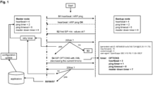
- Fig. 1 schematically shows a flow chart for determining a minimum timer configuration.
- the invention has the objective to develop an automatic method to determine the fastest switchover time, taking into account the best current values for a switchover mechanism and considering the dynamic aspects as network reliability and speed, system load capacity, and any other external events that could contribute to the switchover timeout.
- the default and minimum fixed timers for switchover are set to the following values.
- Master down timer It is a timer to consider that the master node is down, meaning it is not working properly due to any kind of failure.
- the minimum value for this timer is 3 seconds while the maximum value is 15 seconds. A default value of 5 seconds is used.
- Heartbeat timer The time to send a heartbeat to the other host. As described a heartbeat is a periodic signal generated by a hardware or software to indicate normal operation or to synchronize other parts of a computer system.
- the minimum value for this timer is 1 second while the maximum value is 6 seconds. A default value of 2 seconds is used.
- the master down timer When setting the master down timer and the heartbeat timer, the master down timer must be 2 times larger than the heartbeat timer.
- Ping timer It is the timer interval to send pings to other nodes.
- Ping is a computer network administration software utility used to test the reachability of a host on an Internet Protocol (IP) network. It is available for virtually all operating systems that have networking capability, including most embedded network administration software. Ping measures the round-trip time for messages sent from the originating host to a destination computer that are echoed back to the source. The minimum value for this timer is 3 seconds while the maximum value is 30 seconds. A default value of 10 seconds is used.
- IP Internet Protocol
- Ping timeout - It is the time to receive a ping from the other host.
- the minimum value for this timer is 7 seconds while the maximum value is 60 seconds.
- a default value of 30 seconds is used.
- the ping timeout When setting the ping timer and the ping timeout, the ping timeout must be 2 times larger than the ping timer.
- the master node uses a minimum switchover timer configuration.
- the heartbeat timer is preset to 4 seconds, the ping timer to 2 seconds, the ping timeout to 6 seconds and the master down timer to 8 seconds.
- the system checks whether a heartbeat and/or ARP ping signal from the master node can be received and/or is echoed back to the backup node or a surveillance unit of the network (step S1 in Fig. 1 and in Fig. 2 ). If the heartbeat and/or the ARP ping is echoed back to the backup node or the surveillance unit with the preconfigured minimum timer values, this is also noted in a database. This data collection, for example, allows to configure a retry timer.
- a retry timer is used to control a test cadence and to collect network reliability.
- This retry timer can be configured according to the customer specifications. In a network with dynamic variations, this timer can be set to a low value, whereas in a stable network it could be set to higher values (once a day, for example). It will be activated via the interface of the master node, and once active it will activate the mechanism until it is deactivated again via the interface.
- a first Session Initiation Protocol (SIP) OPTION message is sent from the backup node or a surveillance unit of the network to the master node by using a higher-level layer protocol, namely SIP (see step S2 in Fig. 1 and Fig. 2 ).
- SIP Session Initiation Protocol
- a second SIP OPTION message is sent by the master node with a new SIP header in Extensible Markup Language (XML) format to the backup node (shown as S4 of Fig. 1 ).
- This SIP header contains a new configuration of the switchover timer values.
- the master node receives a "200ok" response from the backup node.
- a configuration update of the switchover timer on the master node is initiated via a network application (see step S5 in Fig. 1 ). Then, depending on the setting of the retry timer, the master node sends another heartbeat and/or ARP ping signal to the backup node or the surveillance unit, but this new ping signal is now based on the altered switchover timer values.
- the system is configured in such a way that when the heartbeat and/or ARP ping is successfully received or echoed back from the master node, the time intervals of the switchover timers are reduced. These altered timer values are forwarded by the SIP OPTION messages with a new header in XML format to the backup node and the master node by the network application via SIP signaling protocol or any other protocol.
- the network application can run inside the master and is responsible to receive the new timer values and update the node with the new configuration using these data. Subsequently, a heartbeat and/or ARP ping is used to check whether these new altered timer values are still functional. This flow will be repeated until the system finds the minimal timer configuration, meaning the minimum time values for the timers at which the system still functions.
- the best-configured success values can be obtained, and they can be stored in a database.
- the retry time could be reduced or even disabled until there is some other network event that triggers the mechanism again (e. g. IPs conflicts, ARP ping failure, etc.). Since network speed variations are constant, this makes the network performance dynamic, so it would be ideal for this tuning loop to run in reduced times.
- the retry timer will be set with a minimum value (for example, 1 second), and a maximum value (1 time a day, for example). This may vary according to customer requirements.
- this retry timer changes dynamically according to the connectivity tests, because if this time becomes fixed, or the times of previous test results stored in a database are used to obtain an average, for example, the opportunity to obtain the best values if the network has improved performance at any given time will be lost.
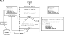
- Fig. 2 is a scenario to recover the communication between the master node and the one or more backup node or a surveillance unit of the network (not shown).
- the steps in this scenario are the same as those in Fig. 1 , except that if the heartbeat and/or ARP ping echo is not received in the given time values by the backup node or the surveillance unit (indicated by "FAIL" in Fig. 2 ) then the backup node or master node sends also a first SIP OPTION message to the master node to determine if it is still active before a switchover is performed (see step S2 in Fig.2 ).
- the master node If the master node is still active, it sends a second SIP OPTION with a new header in XML format to the backup node and the master node with increased switchover timer values (step S8 in Fig.2 ). This re-configuration is repeated until the heartbeat and/or ARP ping is again functional (steps S9/S10 in Fig. 2 ).
- the system can be automatically and dynamically adapted to the network conditions without a premature accidental switchover being made even though the master node is still active but does not appear to be accessible in the defined time interval due to the network conditions.
- ARP ping a system of the state of the art uses the traditional way (ARP ping), if it fails (for the number of times configured), then the switchover is triggered on the backup side, and the communication and adjustment recovery logic with the master starts again until it is reset with the best values again.
- Redundant systems usually work with one Virtual IP (VIP), and two real IPs (master and backup).
- VIP Virtual IP
- master and backup The VIP is used to determine the mastership in the network.
- the redundancy system (the master) is in charge of notifying that it is using the VIP by sending an ARP ping to the network gateway or the surveillance unit.
- the automatic adjustment using the two protocols with different layers such as SIP and ARP ping and the internal recognition of network problems is a differential from what is deployed currently on the enterprise network systems.
Landscapes
- Engineering & Computer Science (AREA)
- Computer Networks & Wireless Communication (AREA)
- Theoretical Computer Science (AREA)
- Signal Processing (AREA)
- General Engineering & Computer Science (AREA)
- Quality & Reliability (AREA)
- General Physics & Mathematics (AREA)
- Physics & Mathematics (AREA)
- General Business, Economics & Management (AREA)
- Business, Economics & Management (AREA)
- Multimedia (AREA)
- Computer Security & Cryptography (AREA)
- General Health & Medical Sciences (AREA)
- Cardiology (AREA)
- Health & Medical Sciences (AREA)
- Computer Hardware Design (AREA)
- Data Exchanges In Wide-Area Networks (AREA)
- Telephonic Communication Services (AREA)
- Hardware Redundancy (AREA)
Claims (12)
- Verfahren zur automatischen Abstimmung eines Umschaltzeitgebers in Netzsystemen oder Notfallsystemen der nächsten Generation, wobei das Verfahren die folgenden Schritte umfasst:Schritt S1) Senden, durch einen Masterknoten, eines Heartbeats und/oder ARP-Pings an einen oder mehrere Backup-Knoten und/oder eine Überwachungseinheit gemäß vorkonfigurierten Umschaltzeitgeberwerten, um zu prüfen, ob der Masterknoten noch aktiv ist;Schritt S2) Senden, durch den einen oder die mehreren Backup-Knoten und/oder die Überwachungseinheit, einer zusätzlichen ersten OPTION-Nachricht des Session Initiation Protocol, SIP, an den Masterknoten, nachdem der Heartbeat und/oder der ARP-Ping empfangen wurde oder wenn der Heartbeat und/oder der ARP-Ping nicht gemäß den Umschaltzeitgeberwerten empfangen wird;Schritt S3) Durchführen, durch einen Administrator oder eine Verwaltungseinheit des Netzes, einer Umschaltung oder eines Failovers zu einem Backup-Knoten für den Fall, dass die erste SIP-OPTION-Nachricht von dem Masterknoten nicht gemäß einem vorkonfigurierten Zeitwert mit "200ok" beantwortet wird.
- Verfahren nach Anspruch 1, wobei nach dem Senden, durch den einen oder die mehreren Backup-Knoten und/oder die Überwachungseinheit, der zusätzlichen ersten OPTION-Nachricht des Session Initiation Protocol, SIP, an den Masterknoten, das Verfahren ferner umfasst:Schritt S4) Rekalibrieren und Verringern, durch den Masterknoten, der Umschaltzeitgeberwerte durch Senden einer zweiten SIP-OPTION-Nachricht, die einen neuen Header umfasst, der die geänderten Umschaltzeitgeberwerte anzeigt, für den Fall, dass der Heartbeat und/oder der ARP-Ping erfolgreich durchgeführt worden sind und die erste SIP-OPTION durch den Masterknoten mit "200ok" in der vorkonfigurierten Zeit beantwortet worden ist;Schritt S5) Speichern, durch den Masterknoten, der Umschaltzeitgeberwerte, die keinen Heartbeat- und/oder ARP-Ping-Fehler verursacht haben, in einer Datenbank;Schritt S6) Wiederholen der Schritte S1, S2, S4 und S5, bis der Heartbeat und/oder ARP-Ping ausfällt; undSchritt S7) Rekalibrieren, durch den Masterknoten, der zuletzt gespeicherten Umschaltzeitgeberwerte, die keinen Heartbeat- und/oder ARP-Ping-Fehler verursacht haben, aus der Datenbank unter Verwendung einer SIP OPTION-Nachricht, die einen Header umfasst, der die zuletzt gespeicherten Umschaltzeitgeberwerte angibt.
- Verfahren nach einem der vorangehenden Ansprüche, wobei das Verfahren nach dem Senden, durch den einen oder die mehreren Backup-Knoten und/oder die Überwachungseinheit, der zusätzlichen ersten OPTION-Nachricht des Session Initiation Protocol, SIP, an den Masterknoten, ferner umfasst:Schritt S8) Rekalibrieren und Erhöhen, durch den Masterknoten, der Umschaltzeitgeberwerte durch Senden einer zweiten SIP-OPTION-Nachricht, die einen neuen Header umfasst, der die geänderten Umschaltzeitgeberwerte anzeigt, für den Fall, dass der Heartbeat und/oder der ARP-Ping fehlschlägt und die erste SIP OPTION-Nachricht durch den Masterknoten mit "200ok" in der vorkonfigurierten Zeit beantwortet wurde;Schritt S9) Wiederholen des Verfahrens der Schritte S1, S2 und S8, bis der Heartbeat und/oder ARP-Ping erfolgreich ist; undSchritt S10) Speichern, durch den Masterknoten, der Umschaltzeitgeberwerte, die keinen Heartbeat- und/oder ARP-Ping-Fehler verursacht haben, in einer Datenbank.
- Verfahren nach einem der vorhergehenden Ansprüche, wobei die Überwachungseinheit mindestens ein anderer Server des Netzwerkes, ein Gateway des Netzwerkes, eine Border Control Function, BCF, eine Session Border Control, SBC, oder eine andere Grenznetzausrüstung als solche ist.
- Verfahren nach einem der vorhergehenden Ansprüche, wobei der Masterknoten und der eine oder die mehreren Backup-Knoten jeweils eine reale Internetprotokoll, IP, -Adresse aufweisen und/oder wobei der Masterknoten zusätzlich eine virtuelle IP-Adresse, VIP, aufweist, um die Herrschaft im Netz zu bestimmen.
- Verfahren nach einem der vorhergehenden Ansprüche, wobei die Umschaltzeitgeberwerte einen Master-Ausfallzeitgeber umfassen, um zu berücksichtigen, dass der Masterknoten nicht aktiv oder ausgefallen ist, einen Heartbeat-Timer, der die Zeit ist, um einen Heartbeat an einen anderen Knoten im Netzwerk zu senden, einen Ping-Timer, der das Intervall ist, um Pings an einen anderen Knoten im Netzwerk zu senden, einen Ping-Timeout, der das Intervall ist, um einen Ping von einem anderen Knoten im Netzwerk zu empfangen.
- Das Verfahren nach einem der vorhergehenden Ansprüche, wobei das Verfahren ferner die Verwendung, durch die Session Border Control, SBC, oder jede andere Grenznetzausrüstung als solche, eines Wiederholungszeitgebers umfasst, um eine Testkadenz zu steuern und die Netzzuverlässigkeit zu erfassen.
- Verfahren nach Anspruch 7, wobei der Wiederholungszeitgeber in einem Netz mit dynamischen Schwankungen dynamisch auf einen Wert von Sekunden, Minuten oder Stunden gesetzt wird und/oder wobei der Wiederholungszeitgeber in einem stabilen Netz dynamisch auf einen Wert von Minuten, Stunden oder Tagen gesetzt wird; und wobei die dynamische Einstellung entsprechend der Konnektivität des Masterknotens im Netz durchgeführt wird.
- System zur automatischen Abstimmung eines Umschaltzeitgebers in Netzsystemen oder Notfallsystemen der nächsten Generation, wobei das System so konfiguriert ist, dass es das Verfahren nach einem der Ansprüche 1 bis 8 durchführt.
- System nach Anspruch 9, wobei das System mindestens einen Masterknoten, einen oder mehrere Backup-Knoten, eine Überwachungseinheit, einen vorkonfigurierten Satz von Umschaltzeitgeberwerten und eine Datenbank umfasst.
- System nach Anspruch 9 oder 10, wobei das System ferner eine Anwendung umfasst, die so konfiguriert ist, dass sie die Umschaltzeitgeber neu kalibriert.
- System nach einem der Ansprüche 9 bis 11, wobei das System ferner einen Administrator oder eine Administratoreinheit umfasst, der/die so konfiguriert ist, dass er/sie die Umschaltung oder das Failover zu dem einen oder mehreren Backup-Knoten durchführt, wenn der Masterknoten ausgefallen oder nicht aktiv ist.
Priority Applications (2)
| Application Number | Priority Date | Filing Date | Title |
|---|---|---|---|
| EP22191989.7A EP4329263B1 (de) | 2022-08-24 | 2022-08-24 | Verfahren und system zur automatischen abstimmung eines umschaltzeitgebers in netzwerksystemen oder notfallsystemen der nächsten generation |
| US18/295,288 US11956287B2 (en) | 2022-08-24 | 2023-04-04 | Method and system for automated switchover timers tuning on network systems or next generation emergency systems |
Applications Claiming Priority (1)
| Application Number | Priority Date | Filing Date | Title |
|---|---|---|---|
| EP22191989.7A EP4329263B1 (de) | 2022-08-24 | 2022-08-24 | Verfahren und system zur automatischen abstimmung eines umschaltzeitgebers in netzwerksystemen oder notfallsystemen der nächsten generation |
Publications (2)
| Publication Number | Publication Date |
|---|---|
| EP4329263A1 EP4329263A1 (de) | 2024-02-28 |
| EP4329263B1 true EP4329263B1 (de) | 2025-04-30 |
Family
ID=83319316
Family Applications (1)
| Application Number | Title | Priority Date | Filing Date |
|---|---|---|---|
| EP22191989.7A Active EP4329263B1 (de) | 2022-08-24 | 2022-08-24 | Verfahren und system zur automatischen abstimmung eines umschaltzeitgebers in netzwerksystemen oder notfallsystemen der nächsten generation |
Country Status (2)
| Country | Link |
|---|---|
| US (1) | US11956287B2 (de) |
| EP (1) | EP4329263B1 (de) |
Family Cites Families (5)
| Publication number | Priority date | Publication date | Assignee | Title |
|---|---|---|---|---|
| US7995466B2 (en) * | 2008-03-26 | 2011-08-09 | Avaya Inc. | Failover/failback trigger using SIP messages in a SIP survivable configuration |
| US20120124431A1 (en) | 2010-11-17 | 2012-05-17 | Alcatel-Lucent Usa Inc. | Method and system for client recovery strategy in a redundant server configuration |
| US9426833B2 (en) * | 2013-03-01 | 2016-08-23 | T-Mobile Usa, Inc. | Systems and methods for emergency call route failover |
| US20190081886A1 (en) * | 2017-09-12 | 2019-03-14 | Patton Electronics Company | Method and system for surviving outages in hosted sip service networks |
| US10909008B2 (en) * | 2018-12-17 | 2021-02-02 | Ribbon Communications Operating Company, Inc. | Methods and apparatus for detecting, eliminating and/or mitigating split brain occurrences in high availability systems |
-
2022
- 2022-08-24 EP EP22191989.7A patent/EP4329263B1/de active Active
-
2023
- 2023-04-04 US US18/295,288 patent/US11956287B2/en active Active
Also Published As
| Publication number | Publication date |
|---|---|
| US20240073260A1 (en) | 2024-02-29 |
| EP4329263A1 (de) | 2024-02-28 |
| US11956287B2 (en) | 2024-04-09 |
Similar Documents
| Publication | Publication Date | Title |
|---|---|---|
| US6658595B1 (en) | Method and system for asymmetrically maintaining system operability | |
| CN109344014B (zh) | 一种主备切换方法、装置及通信设备 | |
| EP1697843B1 (de) | System und verfahren zur verwaltung von protokollnetzwerkausfällen in einem cluster-system | |
| US7076696B1 (en) | Providing failover assurance in a device | |
| US20140095925A1 (en) | Client for controlling automatic failover from a primary to a standby server | |
| US11307945B2 (en) | Methods and apparatus for detecting, eliminating and/or mitigating split brain occurrences in high availability systems | |
| KR20130096297A (ko) | 중복 서버 구성에서의 클라이언트 복구 전략을 위한 방법 및 시스템 | |
| JP2009239891A (ja) | Sip生残り可能な構成においてsipメッセージを使用したフェイルオーバ・トリガ/フェイルバック・トリガ | |
| CN115277379B (zh) | 分布式锁容灾处理方法、装置、电子设备及存储介质 | |
| WO2019049433A1 (ja) | クラスタシステム、クラスタシステムの制御方法、サーバ装置、制御方法、及びプログラムが格納された非一時的なコンピュータ可読媒体 | |
| US20250254121A1 (en) | Device management method, device, system, and storage medium | |
| KR101075462B1 (ko) | 서브넷에서 마스터 노드를 선출하는 방법 | |
| EP4329263B1 (de) | Verfahren und system zur automatischen abstimmung eines umschaltzeitgebers in netzwerksystemen oder notfallsystemen der nächsten generation | |
| CN117201507B (zh) | 云平台切换方法、装置、电子设备及存储介质 | |
| CN117560268B (zh) | 集群管理方法及相关装置 | |
| CN118487924A (zh) | 一种事件日志管理方法、装置、设备及可读存储介质 | |
| EP2815549B1 (de) | Verfahren und vorrichtung zur verbesserten handhabung eines ims-knoten-blacklistings | |
| US20200403848A1 (en) | Dynamic distribution of bidirectional forwarding detection echo sessions across a multi-processor system | |
| US7958386B2 (en) | Method and apparatus for providing a reliable fault management for a network | |
| JP2998789B2 (ja) | フォールトトレラント広帯域ネットワーク管理システム | |
| CN117493081A (zh) | 高可用架构的处理方法和装置 | |
| CN100473018C (zh) | 用于替代接通空间上分开的交换系统的方法 | |
| EP2456165B1 (de) | Serverausfall in einer Telefonieserver-Doppelverbindungsarchitektur | |
| CN121125454A (zh) | 一种多服务器集群的故障切换方法、设备及介质 | |
| KR100233245B1 (ko) | 고속무선호출 시스템에서의 이중화 제어방법 |
Legal Events
| Date | Code | Title | Description |
|---|---|---|---|
| PUAI | Public reference made under article 153(3) epc to a published international application that has entered the european phase |
Free format text: ORIGINAL CODE: 0009012 |
|
| STAA | Information on the status of an ep patent application or granted ep patent |
Free format text: STATUS: THE APPLICATION HAS BEEN PUBLISHED |
|
| AK | Designated contracting states |
Kind code of ref document: A1 Designated state(s): AL AT BE BG CH CY CZ DE DK EE ES FI FR GB GR HR HU IE IS IT LI LT LU LV MC MK MT NL NO PL PT RO RS SE SI SK SM TR |
|
| STAA | Information on the status of an ep patent application or granted ep patent |
Free format text: STATUS: REQUEST FOR EXAMINATION WAS MADE |
|
| 17P | Request for examination filed |
Effective date: 20240819 |
|
| RBV | Designated contracting states (corrected) |
Designated state(s): AL AT BE BG CH CY CZ DE DK EE ES FI FR GB GR HR HU IE IS IT LI LT LU LV MC MK MT NL NO PL PT RO RS SE SI SK SM TR |
|
| REG | Reference to a national code |
Ref country code: DE Ref legal event code: R079 Free format text: PREVIOUS MAIN CLASS: H04L0065110400 Ipc: G06F0011070000 Ref country code: DE Ref legal event code: R079 Ref document number: 602022013816 Country of ref document: DE Free format text: PREVIOUS MAIN CLASS: H04L0065110400 Ipc: G06F0011070000 |
|
| RAP1 | Party data changed (applicant data changed or rights of an application transferred) |
Owner name: UNIFY BETEILIGUNGSVERWALTUNG GMBH & CO. KG |
|
| GRAP | Despatch of communication of intention to grant a patent |
Free format text: ORIGINAL CODE: EPIDOSNIGR1 |
|
| STAA | Information on the status of an ep patent application or granted ep patent |
Free format text: STATUS: GRANT OF PATENT IS INTENDED |
|
| RIC1 | Information provided on ipc code assigned before grant |
Ipc: H04L 43/0817 20220101ALI20241128BHEP Ipc: H04L 69/40 20220101ALI20241128BHEP Ipc: H04L 65/1104 20220101ALI20241128BHEP Ipc: H04L 69/28 20220101ALI20241128BHEP Ipc: H04L 67/1001 20220101ALI20241128BHEP Ipc: H04L 43/10 20220101ALI20241128BHEP Ipc: H04L 41/0663 20220101ALI20241128BHEP Ipc: G06F 11/20 20060101ALI20241128BHEP Ipc: G06F 11/07 20060101AFI20241128BHEP |
|
| INTG | Intention to grant announced |
Effective date: 20241212 |
|
| GRAS | Grant fee paid |
Free format text: ORIGINAL CODE: EPIDOSNIGR3 |
|
| GRAA | (expected) grant |
Free format text: ORIGINAL CODE: 0009210 |
|
| STAA | Information on the status of an ep patent application or granted ep patent |
Free format text: STATUS: THE PATENT HAS BEEN GRANTED |
|
| AK | Designated contracting states |
Kind code of ref document: B1 Designated state(s): AL AT BE BG CH CY CZ DE DK EE ES FI FR GB GR HR HU IE IS IT LI LT LU LV MC MK MT NL NO PL PT RO RS SE SI SK SM TR |
|
| REG | Reference to a national code |
Ref country code: CH Ref legal event code: EP Ref country code: GB Ref legal event code: FG4D |
|
| REG | Reference to a national code |
Ref country code: IE Ref legal event code: FG4D |
|
| REG | Reference to a national code |
Ref country code: DE Ref legal event code: R096 Ref document number: 602022013816 Country of ref document: DE |
|
| REG | Reference to a national code |
Ref country code: NL Ref legal event code: MP Effective date: 20250430 |
|
| REG | Reference to a national code |
Ref country code: AT Ref legal event code: MK05 Ref document number: 1790664 Country of ref document: AT Kind code of ref document: T Effective date: 20250430 |
|
| PG25 | Lapsed in a contracting state [announced via postgrant information from national office to epo] |
Ref country code: PT Free format text: LAPSE BECAUSE OF FAILURE TO SUBMIT A TRANSLATION OF THE DESCRIPTION OR TO PAY THE FEE WITHIN THE PRESCRIBED TIME-LIMIT Effective date: 20250901 Ref country code: ES Free format text: LAPSE BECAUSE OF FAILURE TO SUBMIT A TRANSLATION OF THE DESCRIPTION OR TO PAY THE FEE WITHIN THE PRESCRIBED TIME-LIMIT Effective date: 20250430 Ref country code: FI Free format text: LAPSE BECAUSE OF FAILURE TO SUBMIT A TRANSLATION OF THE DESCRIPTION OR TO PAY THE FEE WITHIN THE PRESCRIBED TIME-LIMIT Effective date: 20250430 |
|
| PGFP | Annual fee paid to national office [announced via postgrant information from national office to epo] |
Ref country code: DE Payment date: 20250702 Year of fee payment: 4 |
|
| REG | Reference to a national code |
Ref country code: LT Ref legal event code: MG9D |
|
| PG25 | Lapsed in a contracting state [announced via postgrant information from national office to epo] |
Ref country code: GR Free format text: LAPSE BECAUSE OF FAILURE TO SUBMIT A TRANSLATION OF THE DESCRIPTION OR TO PAY THE FEE WITHIN THE PRESCRIBED TIME-LIMIT Effective date: 20250731 Ref country code: NO Free format text: LAPSE BECAUSE OF FAILURE TO SUBMIT A TRANSLATION OF THE DESCRIPTION OR TO PAY THE FEE WITHIN THE PRESCRIBED TIME-LIMIT Effective date: 20250730 |
|
| PG25 | Lapsed in a contracting state [announced via postgrant information from national office to epo] |
Ref country code: PL Free format text: LAPSE BECAUSE OF FAILURE TO SUBMIT A TRANSLATION OF THE DESCRIPTION OR TO PAY THE FEE WITHIN THE PRESCRIBED TIME-LIMIT Effective date: 20250430 Ref country code: NL Free format text: LAPSE BECAUSE OF FAILURE TO SUBMIT A TRANSLATION OF THE DESCRIPTION OR TO PAY THE FEE WITHIN THE PRESCRIBED TIME-LIMIT Effective date: 20250430 |
|
| PG25 | Lapsed in a contracting state [announced via postgrant information from national office to epo] |
Ref country code: BG Free format text: LAPSE BECAUSE OF FAILURE TO SUBMIT A TRANSLATION OF THE DESCRIPTION OR TO PAY THE FEE WITHIN THE PRESCRIBED TIME-LIMIT Effective date: 20250430 |
|
| PG25 | Lapsed in a contracting state [announced via postgrant information from national office to epo] |
Ref country code: HR Free format text: LAPSE BECAUSE OF FAILURE TO SUBMIT A TRANSLATION OF THE DESCRIPTION OR TO PAY THE FEE WITHIN THE PRESCRIBED TIME-LIMIT Effective date: 20250430 |
|
| PG25 | Lapsed in a contracting state [announced via postgrant information from national office to epo] |
Ref country code: AT Free format text: LAPSE BECAUSE OF FAILURE TO SUBMIT A TRANSLATION OF THE DESCRIPTION OR TO PAY THE FEE WITHIN THE PRESCRIBED TIME-LIMIT Effective date: 20250430 |
|
| PGFP | Annual fee paid to national office [announced via postgrant information from national office to epo] |
Ref country code: FR Payment date: 20250703 Year of fee payment: 4 |
|
| PG25 | Lapsed in a contracting state [announced via postgrant information from national office to epo] |
Ref country code: RS Free format text: LAPSE BECAUSE OF FAILURE TO SUBMIT A TRANSLATION OF THE DESCRIPTION OR TO PAY THE FEE WITHIN THE PRESCRIBED TIME-LIMIT Effective date: 20250731 |
|
| PG25 | Lapsed in a contracting state [announced via postgrant information from national office to epo] |
Ref country code: IS Free format text: LAPSE BECAUSE OF FAILURE TO SUBMIT A TRANSLATION OF THE DESCRIPTION OR TO PAY THE FEE WITHIN THE PRESCRIBED TIME-LIMIT Effective date: 20250830 |
|
| PG25 | Lapsed in a contracting state [announced via postgrant information from national office to epo] |
Ref country code: LV Free format text: LAPSE BECAUSE OF FAILURE TO SUBMIT A TRANSLATION OF THE DESCRIPTION OR TO PAY THE FEE WITHIN THE PRESCRIBED TIME-LIMIT Effective date: 20250430 |
|
| PG25 | Lapsed in a contracting state [announced via postgrant information from national office to epo] |
Ref country code: DK Free format text: LAPSE BECAUSE OF FAILURE TO SUBMIT A TRANSLATION OF THE DESCRIPTION OR TO PAY THE FEE WITHIN THE PRESCRIBED TIME-LIMIT Effective date: 20250430 Ref country code: SM Free format text: LAPSE BECAUSE OF FAILURE TO SUBMIT A TRANSLATION OF THE DESCRIPTION OR TO PAY THE FEE WITHIN THE PRESCRIBED TIME-LIMIT Effective date: 20250430 |
|
| PG25 | Lapsed in a contracting state [announced via postgrant information from national office to epo] |
Ref country code: CZ Free format text: LAPSE BECAUSE OF FAILURE TO SUBMIT A TRANSLATION OF THE DESCRIPTION OR TO PAY THE FEE WITHIN THE PRESCRIBED TIME-LIMIT Effective date: 20250430 |