EP4329086A1 - Apparatuses, systems, and methods for reducing transmission line insertion loss using trimming lines - Google Patents
Apparatuses, systems, and methods for reducing transmission line insertion loss using trimming lines Download PDFInfo
- Publication number
- EP4329086A1 EP4329086A1 EP23191160.3A EP23191160A EP4329086A1 EP 4329086 A1 EP4329086 A1 EP 4329086A1 EP 23191160 A EP23191160 A EP 23191160A EP 4329086 A1 EP4329086 A1 EP 4329086A1
- Authority
- EP
- European Patent Office
- Prior art keywords
- coplanar waveguide
- mesh
- region
- trimming line
- trimming
- Prior art date
- Legal status (The legal status is an assumption and is not a legal conclusion. Google has not performed a legal analysis and makes no representation as to the accuracy of the status listed.)
- Pending
Links
- 238000009966 trimming Methods 0.000 title claims abstract description 115
- 238000000034 method Methods 0.000 title claims abstract description 27
- 238000003780 insertion Methods 0.000 title claims description 26
- 230000037431 insertion Effects 0.000 title claims description 26
- 230000005540 biological transmission Effects 0.000 title description 10
- 239000000463 material Substances 0.000 claims description 42
- 229910052751 metal Inorganic materials 0.000 claims description 32
- 239000002184 metal Substances 0.000 claims description 32
- 230000003190 augmentative effect Effects 0.000 claims description 12
- 238000005530 etching Methods 0.000 claims description 11
- 239000012811 non-conductive material Substances 0.000 claims description 10
- 238000004519 manufacturing process Methods 0.000 abstract description 5
- 230000008569 process Effects 0.000 description 8
- 238000010586 diagram Methods 0.000 description 7
- 239000011521 glass Substances 0.000 description 7
- 230000003287 optical effect Effects 0.000 description 7
- 238000004088 simulation Methods 0.000 description 7
- 239000004020 conductor Substances 0.000 description 5
- 238000005259 measurement Methods 0.000 description 5
- 210000003128 head Anatomy 0.000 description 4
- 238000012545 processing Methods 0.000 description 4
- 238000005520 cutting process Methods 0.000 description 3
- 210000000613 ear canal Anatomy 0.000 description 3
- 230000000694 effects Effects 0.000 description 3
- 230000006870 function Effects 0.000 description 3
- 238000012986 modification Methods 0.000 description 3
- 230000004048 modification Effects 0.000 description 3
- 230000000007 visual effect Effects 0.000 description 3
- 241000226585 Antennaria plantaginifolia Species 0.000 description 2
- 230000008713 feedback mechanism Effects 0.000 description 2
- 230000003993 interaction Effects 0.000 description 2
- 239000004973 liquid crystal related substance Substances 0.000 description 2
- 238000003754 machining Methods 0.000 description 2
- 238000003860 storage Methods 0.000 description 2
- RYGMFSIKBFXOCR-UHFFFAOYSA-N Copper Chemical compound [Cu] RYGMFSIKBFXOCR-UHFFFAOYSA-N 0.000 description 1
- WHXSMMKQMYFTQS-UHFFFAOYSA-N Lithium Chemical compound [Li] WHXSMMKQMYFTQS-UHFFFAOYSA-N 0.000 description 1
- HBBGRARXTFLTSG-UHFFFAOYSA-N Lithium ion Chemical compound [Li+] HBBGRARXTFLTSG-UHFFFAOYSA-N 0.000 description 1
- XUIMIQQOPSSXEZ-UHFFFAOYSA-N Silicon Chemical compound [Si] XUIMIQQOPSSXEZ-UHFFFAOYSA-N 0.000 description 1
- BQCADISMDOOEFD-UHFFFAOYSA-N Silver Chemical compound [Ag] BQCADISMDOOEFD-UHFFFAOYSA-N 0.000 description 1
- ATJFFYVFTNAWJD-UHFFFAOYSA-N Tin Chemical compound [Sn] ATJFFYVFTNAWJD-UHFFFAOYSA-N 0.000 description 1
- 241000746998 Tragus Species 0.000 description 1
- HCHKCACWOHOZIP-UHFFFAOYSA-N Zinc Chemical compound [Zn] HCHKCACWOHOZIP-UHFFFAOYSA-N 0.000 description 1
- XLOMVQKBTHCTTD-UHFFFAOYSA-N Zinc monoxide Chemical compound [Zn]=O XLOMVQKBTHCTTD-UHFFFAOYSA-N 0.000 description 1
- 210000000988 bone and bone Anatomy 0.000 description 1
- 238000004422 calculation algorithm Methods 0.000 description 1
- 238000004364 calculation method Methods 0.000 description 1
- 210000000845 cartilage Anatomy 0.000 description 1
- 230000019771 cognition Effects 0.000 description 1
- 229910052802 copper Inorganic materials 0.000 description 1
- 239000010949 copper Substances 0.000 description 1
- 238000012937 correction Methods 0.000 description 1
- 230000008878 coupling Effects 0.000 description 1
- 238000010168 coupling process Methods 0.000 description 1
- 238000005859 coupling reaction Methods 0.000 description 1
- 229910003460 diamond Inorganic materials 0.000 description 1
- 239000010432 diamond Substances 0.000 description 1
- 230000007613 environmental effect Effects 0.000 description 1
- AMGQUBHHOARCQH-UHFFFAOYSA-N indium;oxotin Chemical compound [In].[Sn]=O AMGQUBHHOARCQH-UHFFFAOYSA-N 0.000 description 1
- 230000003155 kinesthetic effect Effects 0.000 description 1
- 239000007788 liquid Substances 0.000 description 1
- 229910052744 lithium Inorganic materials 0.000 description 1
- 229910001416 lithium ion Inorganic materials 0.000 description 1
- 238000013507 mapping Methods 0.000 description 1
- 230000007246 mechanism Effects 0.000 description 1
- 230000015654 memory Effects 0.000 description 1
- 229910001092 metal group alloy Inorganic materials 0.000 description 1
- 238000002156 mixing Methods 0.000 description 1
- 238000005457 optimization Methods 0.000 description 1
- 230000008447 perception Effects 0.000 description 1
- 230000000737 periodic effect Effects 0.000 description 1
- 230000002093 peripheral effect Effects 0.000 description 1
- 229920000642 polymer Polymers 0.000 description 1
- 210000001747 pupil Anatomy 0.000 description 1
- 208000014733 refractive error Diseases 0.000 description 1
- 230000004044 response Effects 0.000 description 1
- 230000002207 retinal effect Effects 0.000 description 1
- 230000035807 sensation Effects 0.000 description 1
- 230000035945 sensitivity Effects 0.000 description 1
- 230000021317 sensory perception Effects 0.000 description 1
- 230000008054 signal transmission Effects 0.000 description 1
- 229910052710 silicon Inorganic materials 0.000 description 1
- 239000010703 silicon Substances 0.000 description 1
- 229910052709 silver Inorganic materials 0.000 description 1
- 239000004332 silver Substances 0.000 description 1
- 239000000758 substrate Substances 0.000 description 1
- 238000010408 sweeping Methods 0.000 description 1
- 229910052718 tin Inorganic materials 0.000 description 1
- 239000011135 tin Substances 0.000 description 1
- 238000012549 training Methods 0.000 description 1
- -1 without limitation Substances 0.000 description 1
- 210000000707 wrist Anatomy 0.000 description 1
- 229910052725 zinc Inorganic materials 0.000 description 1
- 239000011701 zinc Substances 0.000 description 1
Images


Classifications
-
- H—ELECTRICITY
- H01—ELECTRIC ELEMENTS
- H01P—WAVEGUIDES; RESONATORS, LINES, OR OTHER DEVICES OF THE WAVEGUIDE TYPE
- H01P3/00—Waveguides; Transmission lines of the waveguide type
- H01P3/003—Coplanar lines
-
- H—ELECTRICITY
- H01—ELECTRIC ELEMENTS
- H01P—WAVEGUIDES; RESONATORS, LINES, OR OTHER DEVICES OF THE WAVEGUIDE TYPE
- H01P11/00—Apparatus or processes specially adapted for manufacturing waveguides or resonators, lines, or other devices of the waveguide type
- H01P11/001—Manufacturing waveguides or transmission lines of the waveguide type
- H01P11/003—Manufacturing lines with conductors on a substrate, e.g. strip lines, slot lines
-
- H—ELECTRICITY
- H01—ELECTRIC ELEMENTS
- H01Q—ANTENNAS, i.e. RADIO AERIALS
- H01Q1/00—Details of, or arrangements associated with, antennas
- H01Q1/27—Adaptation for use in or on movable bodies
- H01Q1/273—Adaptation for carrying or wearing by persons or animals
-
- H—ELECTRICITY
- H01—ELECTRIC ELEMENTS
- H01Q—ANTENNAS, i.e. RADIO AERIALS
- H01Q1/00—Details of, or arrangements associated with, antennas
- H01Q1/36—Structural form of radiating elements, e.g. cone, spiral, umbrella; Particular materials used therewith
- H01Q1/364—Structural form of radiating elements, e.g. cone, spiral, umbrella; Particular materials used therewith using a particular conducting material, e.g. superconductor
Definitions
- the present disclosure is generally directed to apparatuses, systems, and methods that may implement one or more trimming lines to reduce transmission line insertion loss.
- Modern mobile and artificial reality devices e.g., augmented reality (AR) and/or virtual reality glasses
- AR augmented reality
- some of these form factors may attempt to move the existing antennas from being located in frames of the augmented reality devices to being located on one or more lenses of the augmented reality devices.
- transparent conductive (e.g., metal) meshes may be implemented as antennas on the surface of, for example, AR glass lenses.
- antenna feed energy may be met with a large insertion loss into the conductive mesh. This may, in turn, reduce the effectiveness of the antennas.
- the present disclosure identifies and addresses a need for additional apparatuses, systems, and methods for reducing insertion loss into conductive mesh of antenna feed energy.
- a coplanar waveguide comprising: a signal region and a ground region; a first trimming line positioned on the signal region; and a second trimming line positioned on the ground region, wherein the first trimming line and the second trimming line form a floating region in the coplanar waveguide that is configured to receive an input radio frequency (RF) signal.
- RF radio frequency
- the floating region in the coplanar waveguide may receive the input RF signal at a reduced insertion loss below a predetermined threshold.
- At least one of the first trimming line or the second trimming line may be etched into the coplanar waveguide at a specified location.
- the etching may remove at least a portion of mesh wire along the position of the first or second trimming lines.
- At least one of the first or second trimming lines may be additively applied by placing nonconductive material over a wire mesh affixed to the coplanar waveguide.
- the wire mesh may be part of a transparent metal mesh antenna.
- the coplanar waveguide may further comprise at least a portion of fill material configured to return a metal density of the transparent metal mesh antenna to a previously established level of prior to an implementation of the trimming lines.
- a system comprising the coplanar waveguide of the first aspect.
- the system may further comprise an augmented reality device.
- the coplanar waveguide may be included in a lens of the augmented reality device.
- a method comprising: positioning, within a signal region included in a coplanar waveguide, a first trimming line; and positioning, within a ground region included in the coplanar waveguide, a second trimming line, wherein positioning the first trimming line and the second trimming line forms a floating region in the coplanar waveguide that is configured to receive an input radio frequency (RF) signal.
- RF radio frequency
- Positioning the first trimming line within the signal region included in the coplanar waveguide may comprise etching the first trimming line into the coplanar waveguide at a specified location within the signal region included in the coplanar waveguide.
- Positioning the second trimming line within the ground region included in the coplanar waveguide may comprise etching the second trimming line into the coplanar waveguide at an additional specified location within the ground region included in the coplanar waveguide.
- Positioning the first trimming line within the signal region included in the coplanar waveguide may comprise additively applying the first trimming line by placing nonconductive mesh over a wire mesh affixed to the coplanar waveguide.
- Positioning the second trimming line within the ground region included in the coplanar waveguide may comprise additively applying the first trimming line by placing nonconductive mesh over the wire mesh affixed to the coplanar waveguide.
- the method may further comprise including the coplanar waveguide in a lens of an augmented reality device.
- the one or more trimming lines may be used in transparent conductive meshes to reduce insertion loss in the antennas that are formed thereby.
- Embodiments of the present disclosure may reduce transmission line insertion loss by implementing one or more trimming lines (alternatively referred to herein as "nonconductive regions").
- the trimming lines may be implemented in conjunction with a transparent metal mesh that is embedded within or is otherwise affixed to a CPW.
- a trimming line may be implemented on a signal region of the CPW, and an additional trimming line may be implemented on a ground region. This may create a floating region or branch region in the CPW between a signal current and a ground current. This floating region may reduce insertion loss in the CPW. As such, when a signal is applied to the transparent conductive mesh, the signal may experience a much lower insertion loss than would otherwise be experienced without the trimming lines and without the floating region.
- the embodiments herein may define the signal and ground regions, and then define their outlines so that few or no metal branches grow out of them.
- the outline of the signal and ground may be defined so that there is a branch between the signal and ground that is at least partially or entirely floating. This may improve insertion loss when the branch is fully suspended compared to when the branch extends from the signal or ground. Then, in some embodiments, conductors may be added to keep the conductor density constant.
- the trimming lines may be applied to the CPW and/or the conductive mesh in a variety of ways.
- the trimming lines may be applied by etching or cutting the CPW in specific locations in the ground and signal regions. This may remove small portions of the transparent conductive mesh.
- trimming lines may be applied additively by placing nonconductive material over portions of conductive mesh wires. Implementing trimming lines in this manner may greatly reduce insertion loss and may thus greatly enhance the operating efficiency of the transparent metal mesh antenna. Additional or alternative embodiments may place dummy fill material in the conductive mesh to return the metal density of the mesh to the level of metal density that existed before the trimming lines were etched out or before the trimming lines were positioned onto the metal mesh.
- a system may be provided.
- the system may include a CPW that has a signal region and a ground region.
- the system may also include a first trimming line positioned on the signal region of the CPW, and a second trimming line positioned on the ground region of the CPW.
- the first and second trimming lines may thereby establish a floating region in the CPW that configured to receive an input radio frequency (RF) signal.
- RF radio frequency
- the floating region in the CPW may exhibit characteristics that allow it to receive the input RF signal at a reduced insertion loss. This reduced insertion loss may improve the functionality of the transparent antenna or other similar transmission line.
- the trimming lines may be etched into the CPW in specified locations. In such cases, the etching process may remove at least a portion of mesh wire along the position of the trimming lines. This removed wire may create the floating regions in the CPW.
- the trimming lines may be additively applied by placing nonconductive material over the wire mesh that is affixed to the CPW. Thus, nonconductive material may be placed on top of portions of a wire mesh that is part of a transparent metal mesh antenna. The nonconductive material may prevent current from flowing past the trimming lines, thereby creating a floating region that provides reduced insertion loss for incoming signals. In at least some cases, one or more portions of fill material may be implemented to restore a metal mesh's density.
- fill material may be added to a conductive mesh to return the metal density of a transparent mesh antenna to a previously established level before trimming lines were implemented. Restoring the metal density may improve the operating functionality of the conductive mesh.
- This conductive mesh may be used with various mobile electronic devices including augmented reality glasses, smart watches, or other similar devices.
- FIG. 1 is a perspective view 100 of a simulation model 102 for a CPW 104 (CPW 104) in accordance with some of the embodiments disclosed herein.
- simulation model 102 includes CPW 104, which simulation model 102 defines in terms of perfect electrical conductor (PEC) regions 106 (e.g., PEC 106(A), PEC 106(B), and PEC 106(C)), periodic boundary condition (PBC) regions 108 (e.g., PBC region 108(A) and PBC region 108(B)).
- PEC perfect electrical conductor
- PEC periodic boundary condition
- simulation model 102 simulates CPW 104 as including or comprising a perfect magnetic conductor (PMC) region 110.
- PMC perfect magnetic conductor
- FIG. 2 is a detailed perspective view 200 of simulation model 102 that includes CPW 104.
- CPW 104 includes a mesh 202 positioned, affixed to, mounted to, placed upon, etched into, and/or formed from a base material 204.
- mesh 202 may include a transparent conductive metal mesh.
- Mesh 202 may include any suitable metal, metal alloy, or other electrically conductive material including, without limitation, copper, silver, tin, indium tin oxide (ITO), zinc, zinc oxide (ZnO), and so forth.
- CPW 104 and/or mesh 202 may include a signal region 206 and a ground region 208 that may be separated and/or defined by a trimming line 210.
- Trimming line 210 may be any suitable conductorless region that separates conductive regions of mesh 202 from one another. As shown, trimming line 210 transects mesh 202 along a y-axis of CPW 104. As trimming line 210 represents a conductorless region, trimming line 210 may therefore prevent current from passing from signal region 206 to ground region 208 and vice versa. In additional or alternative embodiments, trimming line 210 may, at least partially, electrically and/or magnetically separate and/or isolate at least a portion of signal region 206 from at least a portion of ground region 208 and vice versa.
- FIG. 3 includes a view 300 of a diagram that illustrates and/or describes various relationships and/or attributes of an example mesh 302.
- example mesh 302 may include or represent attributes of a possible implementation of mesh 202.
- example mesh 302 may include or be comprised of a plurality of example segments 304.
- Each example segment 304 may have a length ML , a width of ML , and a depth of t.
- each example segment 304 may have an electrical conductivity represented by ⁇ .
- example mesh 302 has a square aperture and may have a pitch MP (measured from the center of each example segment 304 of example mesh 302) equal to ML.
- FIG. 4 includes a view 400 of equations 402 and table 404 that further illustrates and/or describes possible relationships between and/or values for an example mesh 302.
- BM Dk dielectric constant
- BM Df dissipation factor
- FIG. 5 includes a view 500 of a block diagram that generally illustrates the use of a trimming line with an example mesh in accordance with some embodiments described herein.
- mesh 502 is disposed upon and/or within a suitable base material (e.g., a substrate).
- Trimming line 504 transects mesh 502, dividing mesh 502 into signal region 506 and ground region 508.
- Signal region 506 may conduct signal current 510 (e.g., signal current 510(A) and signal current 510(B)) and ground region 508 may conduct ground current 512 (e.g., ground current 512(A) and ground current 512(B)).
- Trimming line 504 may cause at least a partial disruption and/or interruption in transmission of signal current 510 and/or ground current 512 by mesh 502 via signal sections 514 (signal section 514(A), signal section 514(B), and signal section 514(C)) and/or ground sections 516 (e.g., ground section 516(A), ground section 516(B), and/or ground section 516(C)).
- This disruption or interruption may effectively create "floating" sections 518 (e.g., floating section 518(A), floating section 518(B), and/or floating section 518(C)) that may be electrically isolated from signal sections 514 and/or ground sections 516.
- trimming line 504 may create branches of mesh 502 that may be electrically isolated from signal current and/or ground current, such as signal branches 520 (e.g., ground branch 520(A) and ground branch 520(B)) and signal branches 522 (e.g., signal branch 522(A) and signal branch 522(B)).
- signal branches 520 e.g., ground branch 520(A) and ground branch 520(B)
- signal branches 522 e.g., signal branch 522(A) and signal branch 522(B)
- FIG. 5 The configuration shown in FIG. 5 is provided only by way of example or illustration. Additional possible configurations are shown in FIG. 6 .
- trimming lines are noted as regions shaded with downward diagonal lines, ground sections, signal sections, and floating sections are noted by letters "G”, "S”, and "F" respectively.
- Configuration 600 shows a trimming line that intersects with a cross point or junction in an example mesh.
- Configuration 610 shows a trimming line that intersects with two wires in a single grid of an example mesh.
- Configuration 620 shows a trimming line that intersects with two cross points or junctions in an example mesh, and configuration 630 shows two trimming lines positioned as in configuration 600 and configuration 620, respectively.
- Each of these configurations may result in different configurations for ground branches ( b ( G )), singal branches, and/or floating branches ( b ( G ), b ( S ), and b ( F ) in FIG. 6 , respectively).
- Each of these configurations may impact insertion loss to varying degrees.
- configuration 630 may have an improved loss in comparison to other possible configurations.
- Configuration 610 also shows a possible orthogonal trimming line 612.
- This alternative configuration may be more robust in comparison to other configurations with respect to machining accuracy (e.g., laser processing accuracy) and may be less likely to damage important signal (SIG) and ground (GND) patterns. Cutting in a zig-zag pattern (e.g., orthogonal to mesh wires) may provide more margin for machining of trimming lines.
- some embodiments may include dummy fill material in the conductive mesh.
- This dummy fill material may adjust and/or return a metal density of the conductive mesh to a level of metal density that may have existed prior to positioning and/or etching of the trimming lines relative to the conductive mesh.
- FIG. 7 illustrates various views of some embodiments that may include dummy fill material. As shown in FIG. 7 , view 700 shows a configuration that includes a mesh 702, a first trimming line 704, and a second trimming line 706.
- the configuration shown in view 700 also includes dummy fill material 708 (e.g., dummy fill material 708(A), dummy fill material 708(B), dummy fill material 708(C), and dummy fill material 708(D)) within trimming lines.
- dummy fill material 708 e.g., dummy fill material 708(A), dummy fill material 708(B), dummy fill material 708(C), and dummy fill material 708(D)
- This may be referred to as a "floating" or “totally floating” configuration.
- View 710 shows a configuration that includes a mesh 712, a first trimming line 714, and a second trimming line 716.
- the configuration shown in view 710 also includes dummy fill material 718 (e.g., dummy fill material 718(A), dummy fill material 718(B), dummy fill material 718(C), and dummy fill material 718(D)).
- dummy fill material 718 may be included in and/or connected to a "floating" portion of mesh 712.
- View 720 shows a configuration that includes a mesh 722, a first trimming line 724, and a second trimming line 726.
- the configuration shown in view 720 also includes dummy fill material 728 (e.g., dummy fill material 728(A), dummy fill material 728(B), dummy fill material 728(C), and dummy fill material 728(D)).
- dummy fill material 728 may be included in ant/or connected to a signal portion of mesh 722 and/or a ground portion of mesh 722.
- FIGS. 8-16 illustrate views of example implementations, embodiments, and/or configurations of meshes as described herein.
- FIGS. 8-10 illustrate an example that may be implemented using hexagonal mesh having an aperture of 200 ⁇ m.
- FIG. 8 shows a view 800 of a hexagonal mesh 802 that includes a floating region 804 (denoted by dashed lines) that divides hexagonal mesh 802 into a signal region 806 and a ground region 808.
- floating region 804 may have a width across hexagonal mesh 802 of 802.0 ⁇ m, and may be bounded, formed, and/or defined by one or more trimming lines.
- Hexagonal mesh 802 is shown in FIG. 8 as having a length of 5000.0 ⁇ m.
- Hexagonal mesh 802 may further include, be joined to, and/or abut an additional mesh 810.
- additional mesh 810 is shown as having a width of 1000 ⁇ m.
- Additional mesh 810 may vary from hexagonal mesh 802 in one or more ways, such as having different aperture dimensions, a different compositional structure, one or more different electrical properties, and so forth.
- FIG. 9 shows a detailed view 900 of hexagonal mesh 802.
- hexagonal mesh 802 may have an aperture size of 200.0 ⁇ m.
- FIG. 10 includes a detailed view 1000 of a first possible configuration for a node in a mesh (e.g., hexagonal mesh 802) that joins a first region 1002 of a hexagonal mesh (e.g., floating region 804, signal region 806, and/or ground region 808) to a second region 1002 of a hexagonal mesh (e.g., floating region 804, signal region 806 and/or ground region 808).
- a mesh e.g., hexagonal mesh 802 that joins a first region 1002 of a hexagonal mesh (e.g., floating region 804, signal region 806, and/or ground region 808) to a second region 1002 of a hexagonal mesh (e.g., floating region 804, signal region 806 and/or ground region 808).
- a discontinuity 1006 having a length of 5.0 ⁇ m is formed in the mesh at a point where a wire in region 1004 meets a node and a discontinuity 1008 having a length of 5.0 ⁇ m is formed in the mesh of second region 1002 at a point between nodes.
- dummy fill material 1010 and dummy fill material 1012 each having a length of 5.0 ⁇ m, may be placed within a predetermined distance of the wire (e.g., 5.0 ⁇ m in view 1000) of first region 1004 in an orientation parallel to the wire in first region 1004. This may adjust and/or return a metal density of the mesh to a level of metal density that may have existed prior to the forming of discontinuity 1006 and/or discontinuity 1008.
- FIG. 10 also includes a detailed view 1020 of a second possible configuration for a node in a mesh (e.g., hexagonal mesh 802) that joins a first region 1002 of a hexagonal mesh (e.g., floating region 804, signal region 806, and/or ground region 808) to a second region 1004 of a hexagonal mesh (e.g., floating region 804, signal region 806 and/or ground region 808).
- a mesh e.g., hexagonal mesh 802
- dummy fill material 1010 is positioned parallel to a wire in region 1002 that adjoins a node that joins first region 1002 to second region 1004.
- FIGS. 11-13 illustrate an example that may be implemented using hexagonal mesh having an aperture of 200 ⁇ m.
- the apertures of the mesh are rotated ninety degrees from the apertures of the mesh shown in the examples illustrated in FIGS. 8-10 .
- FIG. 11 shows a view 1100 of a hexagonal mesh 1102 that includes a floating region 1104 (denoted by dashed lines) that divides hexagonal mesh 1102 into a signal region 1106 and a ground region 1108.
- floating region 1104 may have a width across hexagonal mesh 1102 of 926.1 ⁇ m, and may be bounded, formed, and/or defined by one or more trimming lines.
- Hexagonal mesh 1102 is shown in FIG. 11 as having a length of 5000.0 ⁇ m.
- Hexagonal mesh 1102 may further include, be joined to, and/or abut an additional mesh 1110.
- additional mesh 1110 is shown as having a width of 1000 ⁇ m.
- Additional mesh 1110 may vary from hexagonal mesh 1102 in one or more ways, such as having different aperture dimensions, a different compositional structure, one or more different electrical properties, and so forth.
- FIG. 12 shows a detailed view 1200 of hexagonal mesh 1102.
- hexagonal mesh 1102 may have an aperture size of 200.0 ⁇ m.
- FIG. 13 includes a detailed view 1300 of a first possible configuration for a node in a mesh (e.g., hexagonal mesh 1102) that joins a first region 1302 of a hexagonal mesh (e.g., floating region 1104, signal region 1106, and/or ground region 1108) to a second region 1304 of a hexagonal mesh (e.g., floating region 1104, signal region 1106 and/or ground region 1108).
- a mesh e.g., hexagonal mesh 1102
- a discontinuity 1306 having a length of 5.0 ⁇ m is formed in the mesh at a point where a wire in region 1304 meets a node and a discontinuity 1308 having a length of 5.0 ⁇ m is formed in the mesh of second region 1302 at a point between nodes.
- dummy fill material 1310 and dummy fill material 1312, each having a length of 5.0 ⁇ m may be placed within a predetermined distance of the wire (e.g., 5.0 ⁇ m in view 1300) of first region 1304 in an orientation parallel to the wire in first region 1304. This may adjust and/or return a metal density of the mesh to a level of metal density that may have existed prior to the forming of discontinuity 1306 and/or discontinuity 1308.
- FIG. 13 also includes a detailed view 1320 of a second possible configuration for a node in a mesh (e.g., hexagonal mesh 1102) that joins a first region 1302 of a hexagonal mesh (e.g., floating region 1104, signal region 1106, and/or ground region 1108) to a second region 1304 of a hexagonal mesh (e.g., floating region 1104, signal region 1106 and/or ground region 1108).
- a mesh e.g., hexagonal mesh 1102
- first region 1302 of a hexagonal mesh e.g., floating region 1104, signal region 1106, and/or ground region 1108
- second region 1304 of a hexagonal mesh e.g., floating region 1104, signal region 1106 and/or ground region 1108.
- dummy fill material 1310 is positioned parallel to a wire in region 1302 that adjoins a node that joins first region 1302 to second region 1304.
- FIGS. 14-16 illustrate an example that may be implemented using diamond mesh having an aperture of 200 ⁇ m.
- the apertures of the mesh are square and rotated forty-five degrees.
- FIG. 14 shows a view 1400 of a square mesh 1402 that includes a floating region 1404 (denoted by dashed lines) that divides square mesh 1402 into a signal region 1406 and a ground region 1408.
- floating region 1404 may have a width across square mesh 1402 of 851.4 ⁇ m, and may be bounded, formed, and/or defined by one or more trimming lines.
- Square mesh 1402 is shown in FIG. 14 as having a length of 5000.0 ⁇ m.
- Square mesh 1402 may further include, be joined to, and/or abut an additional mesh 1410.
- additional mesh 1410 is shown as having a width of 1000 ⁇ m. Additional mesh 1410 may vary from square mesh 1402 in one or more ways, such as having different aperture dimensions, a different compositional structure, one or more different electrical properties, and so forth.
- FIG. 15 shows a detailed view 1500 of square mesh 1402.
- square mesh 1402 may have an aperture size of 200.0 ⁇ m.
- FIG. 16 includes a detailed view 1600 of a first possible configuration for a node in a mesh (e.g., square mesh 1402) that joins a first region 1602 of a square mesh (e.g., floating region 1404, signal region 1406, and/or ground region 1408) to a second region 1604 of a square mesh (e.g., floating region 1404, signal region 1406 and/or ground region 1408).
- a mesh e.g., square mesh 1402
- a discontinuity 1606 having a length of 5.0 ⁇ m is formed in the mesh at a point where a wire in region 1604 meets a node and a discontinuity 1608 having a length of 5.0 ⁇ m is formed in the mesh of second region 1602 at a point between nodes.
- dummy fill material 1610(A), dummy fill material 1610(B), and dummy fill material 1612, each having a length of 5.0 ⁇ m may be placed within a predetermined distance of the wire (e.g., 5.0 ⁇ m in view 1600) of first region 1604 in an orientation parallel to wire in first region 1604. This may adjust and/or return a metal density of the mesh to a level of metal density that may have existed prior to the forming of discontinuity 1606 and/or discontinuity 1608.
- FIG. 16 also includes a detailed view 1620 of a second possible configuration for a node in a mesh (e.g., square mesh 1402) that joins a first region 1602 of a square mesh (e.g., floating region 1404, signal region 1406, and/or ground region 1408) to a second region 1604 of a square mesh (e.g., floating region 1404, signal region 1406 and/or ground region 1408).
- a mesh e.g., square mesh 1402
- dummy fill material 1610(A) and dummy fill material 1610(B) are each positioned parallel to a wire in region 1602 that adjoins a node that joins first region 1602 to second region 1604.
- FIG. 17 is a flow diagram of an example method 1700 of manufacture for apparatuses or systems for reducing transmission line insertion loss using trimming lines in accordance with some embodiments described herein.
- the steps shown in FIG. 17 may be performed by any suitable instrumentality including, without limitation, a person, a device, a machine, portions of one or more of the same, variations or combinations of one or more of the same, and so forth.
- each of the steps shown in FIG. 17 may represent an algorithm whose structure includes and/or is represented by multiple sub-steps, examples of which are provided in greater detail herein.
- one or more suitable instrumentalities may position, within a signal region included in a CPW, a first trimming line.
- one or more suitable instrumentalities may position, within a ground region included in the CPW, a second trimming line, wherein positioning the first trimming line and the second trimming line forms a floating region in the CPW that is configured to receive an input RF signal.
- the trimming lines may be applied to and/or positioned within the CPW and/or the conductive mesh in a variety of ways. In some embodiments, for instance, as described above, the trimming lines may be applied by etching or cutting the CPW in specific locations in the ground and signal regions. This may remove small portions of the transparent conductive mesh. In additional or alternative embodiments, trimming lines may be applied additively by placing nonconductive material over portions of conductive mesh wires.
- the first and second trimming lines may establish or define a floating region in the CPW that is configured to receive an input radio frequency (RF) signal.
- the floating region in the CPW may exhibit characteristics that allow it to receive the input RF signal at a reduced insertion loss. This reduced insertion loss may improve the functionality of the transparent antenna or other similar transmission line.
- the trimming lines may be etched into the CPW in specified locations. In such cases, the etching process may remove at least a portion of mesh wire along the position of the trimming lines. This removed wire may create the floating regions in the CPW.
- the trimming lines may be additively applied by placing nonconductive material over the wire mesh that is affixed to the CPW. Thus, nonconductive material may be placed on top of portions of a wire mesh that is part of a transparent metal mesh antenna. The nonconductive material may prevent current from flowing past the trimming lines, thereby creating a floating region that provides reduced insertion loss for incoming signals. In at least some cases, one or more portions of fill material may be implemented to restore a metal mesh's density.
- embodiments of the apparatuses, systems, and methods disclosed herein may have many benefits.
- embodiments of the apparatuses, systems and methods disclosed herein may reduce insertion loss of antenna feed energy into one or more antennas implemented by a transparent conductive mesh.
- the signal may experience a much lower insertion loss than would otherwise be experienced absent embodiments of the apparatuses, systems, and methods disclosed herein.
- This reduced insertion loss may improve functionality of the transparent antenna or other similar transmission line.
- fill material may be incorporated into a conductive mesh to return a metal density of a transparent mesh antenna to a previously established level before trimming lines were implemented. Restoring the metal density may improve an operating functionality of the conductive mesh.
- This conductive mesh may be used with various mobile electronic devices including augmented reality glasses, smart watches, or other similar devices.
- Embodiments of the present disclosure may include or be implemented in - conjunction with various types of artificial-reality systems.
- Artificial reality is a form of reality that has been adjusted in some manner before presentation to a user, which may include, for example, a virtual reality, an augmented reality, a mixed reality, a hybrid reality, or some combination and/or derivative thereof.
- Artificial-reality content may include completely computer-generated content or computer-generated content combined with captured (e.g., real-world) content.
- the artificial-reality content may include video, audio, haptic feedback, or some combination thereof, any of which may be presented in a single channel or in multiple channels (such as stereo video that produces a three-dimensional (3D) effect to the viewer).
- artificial reality may also be associated with applications, products, accessories, services, or some combination thereof, that are used to, for example, create content in an artificial reality and/or are otherwise used in (e.g., to perform activities in) an artificial reality.
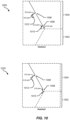
- Artificial-reality systems may be implemented in a variety of different form factors and configurations. Some artificial-reality systems may be designed to work without near-eye displays (NEDs). Other artificial-reality systems may include an NED that also provides visibility into the real world (such as, e.g., augmented-reality system 1800 in FIG. 18 ) or that visually immerses a user in an artificial reality (such as, e.g., virtual-reality system 1900 in FIG. 19 ). While some artificial-reality devices may be self-contained systems, other artificial-reality devices may communicate and/or coordinate with external devices to provide an artificial-reality experience to a user. Examples of such external devices include handheld controllers, mobile devices, desktop computers, devices worn by a user, devices worn by one or more other users, and/or any other suitable external system.
- augmented-reality system 1800 may include an eyewear device 1802 with a frame 1810 configured to hold a left display device 1815(A) and a right display device 1815(B) in front of a user's eyes.
- Display devices 1815(A) and 1815(B) may act together or independently to present an image or series of images to a user.
- augmented-reality system 1800 includes two displays, embodiments of this disclosure may be implemented in augmented-reality systems with a single NED or more than two NEDs.
- augmented-reality system 1800 may include one or more sensors, such as sensor 1840.
- Sensor 1840 may generate measurement signals in response to motion of augmented-reality system 1800 and may be located on substantially any portion of frame 1810.
- Sensor 1840 may represent one or more of a variety of different sensing mechanisms, such as a position sensor, an inertial measurement unit (IMU), a depth camera assembly, a structured light emitter and/or detector, or any combination thereof.
- augmented-reality system 1800 may or may not include sensor 1840 or may include more than one sensor.
- the IMU may generate calibration data based on measurement signals from sensor 1840.
- Examples of sensor 1840 may include, without limitation, accelerometers, gyroscopes, magnetometers, other suitable types of sensors that detect motion, sensors used for error correction of the IMU, or some combination thereof.
- augmented-reality system 1800 may also include a microphone array with a plurality of acoustic transducers 1820(A)-1820(J), referred to collectively as acoustic transducers 1820.
- Acoustic transducers 1820 may represent transducers that detect air pressure variations induced by sound waves.
- Each acoustic transducer 1820 may be configured to detect sound and convert the detected sound into an electronic format (e.g., an analog or digital format).
- 18 may include, for example, ten acoustic transducers: 1820(A) and 1820(B), which may be designed to be placed inside a corresponding ear of the user, acoustic transducers 1820(C), 1820(D), 1820(E), 1820(F), 1820(G), and 1820(H), which may be positioned at various locations on frame 1810, and/or acoustic transducers 1820(I) and 1820(J), which may be positioned on a corresponding neckband 1805.
- ten acoustic transducers 1820(A) and 1820(B), which may be designed to be placed inside a corresponding ear of the user
- acoustic transducers 1820(C), 1820(D), 1820(E), 1820(F), 1820(G), and 1820(H) which may be positioned at various locations on frame 1810
- acoustic transducers 1820(I) and 1820(J) which may be
- acoustic transducers 1820(A)-(J) may be used as output transducers (e.g., speakers).
- acoustic transducers 1820(A) and/or 1820(B) may be earbuds or any other suitable type of headphone or speaker.
- the configuration of acoustic transducers 1820 of the microphone array may vary. While augmented-reality system 1800 is shown in FIG. 18 as having ten acoustic transducers 1820, the number of acoustic transducers 1820 may be greater or less than ten. In some embodiments, using higher numbers of acoustic transducers 1820 may increase the amount of audio information collected and/or the sensitivity and accuracy of the audio information. In contrast, using a lower number of acoustic transducers 1820 may decrease the computing power required by an associated controller 1850 to process the collected audio information. In addition, the position of each acoustic transducer 1820 of the microphone array may vary. For example, the position of an acoustic transducer 1820 may include a defined position on the user, a defined coordinate on frame 1810, an orientation associated with each acoustic transducer 1820, or some combination thereof.
- Acoustic transducers 1820(A) and 1820(B) may be positioned on different parts of the user's ear, such as behind the pinna, behind the tragus, and/or within the auricle or fossa. Or, there may be additional acoustic transducers 1820 on or surrounding the ear in addition to acoustic transducers 1820 inside the ear canal. Having an acoustic transducer 1820 positioned next to an ear canal of a user may enable the microphone array to collect information on how sounds arrive at the ear canal.
- augmented-reality system 1800 may simulate binaural hearing and capture a 3D stereo sound field around about a user's head.
- acoustic transducers 1820(A) and 1820(B) may be connected to augmented-reality system 1800 via a wired connection 1830, and in other embodiments acoustic transducers 1820(A) and 1820(B) may be connected to augmented-reality system 1800 via a wireless connection (e.g., a BLUETOOTH connection).
- acoustic transducers 1820(A) and 1820(B) may not be used at all in conjunction with augmented-reality system 1800.
- Acoustic transducers 1820 on frame 1810 may be positioned in a variety of different ways, including along the length of the temples, across the bridge, above or below display devices 1815(A) and 1815(B), or some combination thereof. Acoustic transducers 1820 may also be oriented such that the microphone array is able to detect sounds in a wide range of directions surrounding the user wearing the augmented-reality system 1800. In some embodiments, an optimization process may be performed during manufacturing of augmented-reality system 1800 to determine relative positioning of each acoustic transducer 1820 in the microphone array.
- augmented-reality system 1800 may include or be connected to an external device (e.g., a paired device), such as neckband 1805.
- an external device e.g., a paired device
- Neckband 1805 generally represents any type or form of paired device.
- the following discussion of neckband 1805 may also apply to various other paired devices, such as charging cases, smart watches, smart phones, wrist bands, other wearable devices, hand-held controllers, tablet computers, laptop computers, other external compute devices, etc.
- neckband 1805 may be coupled to eyewear device 1802 via one or more connectors.
- the connectors may be wired or wireless and may include electrical and/or non-electrical (e.g., structural) components.
- eyewear device 1802 and neckband 1805 may operate independently without any wired or wireless connection between them. While FIG. 18 illustrates the components of eyewear device 1802 and neckband 1805 in example locations on eyewear device 1802 and neckband 1805, the components may be located elsewhere and/or distributed differently on eyewear device 1802 and/or neckband 1805. In some embodiments, the components of eyewear device 1802 and neckband 1805 may be located on one or more additional peripheral devices paired with eyewear device 1802, neckband 1805, or some combination thereof.
- Pairing external devices such as neckband 1805
- augmented-reality eyewear devices may enable the eyewear devices to achieve the form factor of a pair of glasses while still providing sufficient battery and computation power for expanded capabilities.
- Some or all of the battery power, computational resources, and/or additional features of augmented-reality system 1800 may be provided by a paired device or shared between a paired device and an eyewear device, thus reducing the weight, heat profile, and form factor of the eyewear device overall while still retaining desired functionality.
- neckband 1805 may allow components that would otherwise be included on an eyewear device to be included in neckband 1805 since users may tolerate a heavier weight load on their shoulders than they would tolerate on their heads.
- Neckband 1805 may also have a larger surface area over which to diffuse and disperse heat to the ambient environment. Thus, neckband 1805 may allow for greater battery and computation capacity than might otherwise have been possible on a stand-alone eyewear device. Since weight carried in neckband 1805 may be less invasive to a user than weight carried in eyewear device 1802, a user may tolerate wearing a lighter eyewear device and carrying or wearing the paired device for greater lengths of time than a user would tolerate wearing a heavy standalone eyewear device, thereby enabling users to more fully incorporate artificial-reality environments into their day-to-day activities.
- Neckband 1805 may be communicatively coupled with eyewear device 1802 and/or to other devices. These other devices may provide certain functions (e.g., tracking, localizing, depth mapping, processing, storage, etc.) to augmented-reality system 1800.
- neckband 1805 may include two acoustic transducers (e.g., 1820(I) and 1820(J)) that are part of the microphone array (or potentially form their own microphone subarray).
- Neckband 1805 may also include a controller 1825 and a power source 1835.
- Acoustic transducers 1820(I) and 1820(J) of neckband 1805 may be configured to detect sound and convert the detected sound into an electronic format (analog or digital).
- acoustic transducers 1820(I) and 1820(J) may be positioned on neckband 1805, thereby increasing the distance between the neckband acoustic transducers 1820(I) and 1820(J) and other acoustic transducers 1820 positioned on eyewear device 1802.
- increasing the distance between acoustic transducers 1820 of the microphone array may improve the accuracy of beamforming performed via the microphone array.
- the determined source location of the detected sound may be more accurate than if the sound had been detected by acoustic transducers 1820(D) and 1820(E).
- Controller 1825 of neckband 1805 may process information generated by the sensors on neckband 1805 and/or augmented-reality system 1800. For example, controller 1825 may process information from the microphone array that describes sounds detected by the microphone array. For each detected sound, controller 1825 may perform a direction-of-arrival (DOA) estimation to estimate a direction from which the detected sound arrived at the microphone array. As the microphone array detects sounds, controller 1825 may populate an audio data set with the information. In embodiments in which augmented-reality system 1800 includes an inertial measurement unit, controller 1825 may compute all inertial and spatial calculations from the IMU located on eyewear device 1802. A connector may convey information between augmented-reality system 1800 and neckband 1805 and between augmented-reality system 1800 and controller 1825. The information may be in the form of optical data, electrical data, wireless data, or any other transmittable data form. Moving the processing of information generated by augmented-reality system 1800 to neckband 1805 may reduce weight and heat in eyewear device 1802, making it more comfortable to the user.
- Power source 1835 in neckband 1805 may provide power to eyewear device 1802 and/or to neckband 1805.
- Power source 1835 may include, without limitation, lithium-ion batteries, lithium-polymer batteries, primary lithium batteries, alkaline batteries, or any other form of power storage.
- power source 1835 may be a wired power source. Including power source 1835 on neckband 1805 instead of on eyewear device 1802 may help better distribute the weight and heat generated by power source 1835.
- some artificial-reality systems may, instead of blending an artificial reality with actual reality, substantially replace one or more of a user's sensory perceptions of the real world with a virtual experience.
- a head-worn display system such as virtual-reality system 1900 in FIG. 19 , that mostly or completely covers a user's field of view.
- Virtual-reality system 1900 may include a front rigid body 1902 and a band 1904 shaped to fit around a user's head.
- Virtual-reality system 1900 may also include output audio transducers 1906(A) and 1906(B). Furthermore, while not shown in FIG.
- front rigid body 1902 may include one or more electronic elements, including one or more electronic displays, one or more inertial measurement units (IMUs), one or more tracking emitters or detectors, and/or any other suitable device or system for creating an artificial-reality experience.
- IMUs inertial measurement units
- tracking emitters or detectors and/or any other suitable device or system for creating an artificial-reality experience.
- Artificial-reality systems may include a variety of types of visual feedback mechanisms.
- display devices in augmented-reality system 1800 and/or virtual-reality system 1900 may include one or more liquid crystal displays (LCDs), light emitting diode (LED) displays, microLED displays, organic LED (OLED) displays, digital light project (DLP) micro-displays, liquid crystal on silicon (LCoS) micro-displays, and/or any other suitable type of display screen.
- LCDs liquid crystal displays
- LED light emitting diode
- OLED organic LED
- DLP digital light project
- LCD liquid crystal on silicon
- These artificial-reality systems may include a single display screen for both eyes or may provide a display screen for each eye, which may allow for additional flexibility for varifocal adjustments or for correcting a user's refractive error.
- Some of these artificial-reality systems may also include optical subsystems having one or more lenses (e.g., concave or convex lenses, Fresnel lenses, adjustable liquid lenses, etc.) through which a user may view a display screen.
- optical subsystems may serve a variety of purposes, including to collimate (e.g., make an object appear at a greater distance than its physical distance), to magnify (e.g., make an object appear larger than its actual size), and/or to relay (to, e.g., the viewer's eyes) light.
- optical subsystems may be used in a non-pupil-forming architecture (such as a single lens configuration that directly collimates light but results in so-called pincushion distortion) and/or a pupil-forming architecture (such as a multi-lens configuration that produces so-called barrel distortion to nullify pincushion distortion).
- a non-pupil-forming architecture such as a single lens configuration that directly collimates light but results in so-called pincushion distortion
- a pupil-forming architecture such as a multi-lens configuration that produces so-called barrel distortion to nullify pincushion distortion
- some of the artificial-reality systems described herein may include one or more projection systems.
- display devices in augmented-reality system 1800 and/or virtual-reality system 1900 may include microLED projectors that project light (using, e.g., a waveguide) into display devices, such as clear combiner lenses that allow ambient light to pass through.
- the display devices may refract the projected light toward a user's pupil and may enable a user to simultaneously view both artificial-reality content and the real world.
- the display devices may accomplish this using any of a variety of different optical components, including waveguide components (e.g., holographic, planar, diffractive, polarized, and/or reflective waveguide elements), light-manipulation surfaces and elements (such as diffractive, reflective, and refractive elements and gratings), coupling elements, etc.
- waveguide components e.g., holographic, planar, diffractive, polarized, and/or reflective waveguide elements
- light-manipulation surfaces and elements such as diffractive, reflective, and refractive elements and gratings
- coupling elements etc.
- Artificial-reality systems may also be configured with any other suitable type or form of image projection system, such as retinal projectors used in virtual retina displays.
- augmented-reality system 1800 and/or virtual-reality system 1900 may include one or more optical sensors, such as two-dimensional (2D) or 3D cameras, structured light transmitters and detectors, time-of-flight depth sensors, single-beam or sweeping laser rangefinders, 3D LiDAR sensors, and/or any other suitable type or form of optical sensor.
- An artificial-reality system may process data from one or more of these sensors to identify a location of a user, to map the real world, to provide a user with context about real-world surroundings, and/or to perform a variety of other functions.
- the artificial-reality systems described herein may also include one or more input and/or output audio transducers.
- Output audio transducers may include voice coil speakers, ribbon speakers, electrostatic speakers, piezoelectric speakers, bone conduction transducers, cartilage conduction transducers, tragus-vibration transducers, and/or any other suitable type or form of audio transducer.
- input audio transducers may include condenser microphones, dynamic microphones, ribbon microphones, and/or any other type or form of input transducer.
- a single transducer may be used for both audio input and audio output.
- the artificial-reality systems described herein may also include tactile (i.e., haptic) feedback systems, which may be incorporated into headwear, gloves, body suits, handheld controllers, environmental devices (e.g., chairs, floormats, etc.), and/or any other type of device or system.
- Haptic feedback systems may provide various types of cutaneous feedback, including vibration, force, traction, texture, and/or temperature.
- Haptic feedback systems may also provide various types of kinesthetic feedback, such as motion and compliance.
- Haptic feedback may be implemented using motors, piezoelectric actuators, fluidic systems, and/or a variety of other types of feedback mechanisms.
- Haptic feedback systems may be implemented independent of other artificial-reality devices, within other artificial-reality devices, and/or in conjunction with other artificial-reality devices.
- artificial-reality systems may create an entire virtual experience or enhance a user's real-world experience in a variety of contexts and environments. For instance, artificial-reality systems may assist or extend a user's perception, memory, or cognition within a particular environment. Some systems may enhance a user's interactions with other people in the real world or may enable more immersive interactions with other people in a virtual world.
- Artificial-reality systems may also be used for educational purposes (e.g., for teaching or training in schools, hospitals, government organizations, military organizations, business enterprises, etc.), entertainment purposes (e.g., for playing video games, listening to music, watching video content, etc.), and/or for accessibility purposes (e.g., as hearing aids, visual aids, etc.).
- the embodiments disclosed herein may enable or enhance a user's artificial-reality experience in one or more of these contexts and environments and/or in other contexts and environments.
- FIG. 20 shows a view 2000 of an example smartwatch 2002.
- example smartwatch 2002 may include or implement a variety of components that may serve or support various computing functions such as a battery 2004, a central processing unit 2006 ("CPU 2006" in FIG. 20 ) a speaker 2008, and a display 2010.
- example smartwatch 2002 may include various components that may be used as a sensor such as a microphone 2012 and a thermometer 2014.
- example smartwatch 2002 may include any other suitable sensors such as those described herein (e.g., cameras, proximity sensors, motion sensors, etc.).
- example smartwatch 2002 may also include an antenna 2016.
- antenna 2016 may include or represent a plurality of antennas that may be configured to transmit and/or receive a variety of electromagnetic signals and/or configured to implement a plurality of wireless standards.
Landscapes
- Engineering & Computer Science (AREA)
- Manufacturing & Machinery (AREA)
- Shielding Devices Or Components To Electric Or Magnetic Fields (AREA)
Abstract
A disclosed system may include (1) a coplanar waveguide that includes a signal region and a ground region, (2) a first trimming line positioned in the signal region of the coplanar waveguide, and (3) a second trimming line positioned in the ground region of the coplanar waveguide, (4) wherein the first trimming line and the second trimming line form a floating region in the coplanar waveguide that is configured to receive an input radio frequency signal. Various other apparatuses, systems, and methods of manufacture are also disclosed.
Description
- The present disclosure is generally directed to apparatuses, systems, and methods that may implement one or more trimming lines to reduce transmission line insertion loss.
- Modern mobile and artificial reality devices (e.g., augmented reality (AR) and/or virtual reality glasses) continue to grow smaller over time. As such, some of these form factors may attempt to move the existing antennas from being located in frames of the augmented reality devices to being located on one or more lenses of the augmented reality devices. In such cases, transparent conductive (e.g., metal) meshes may be implemented as antennas on the surface of, for example, AR glass lenses.
- In cases where transparent metal meshes are used to create antennas on AR glass lens surfaces, antenna feed energy may be met with a large insertion loss into the conductive mesh. This may, in turn, reduce the effectiveness of the antennas. Hence, the present disclosure identifies and addresses a need for additional apparatuses, systems, and methods for reducing insertion loss into conductive mesh of antenna feed energy.
- According to a first aspect, there is provided a coplanar waveguide comprising: a signal region and a ground region; a first trimming line positioned on the signal region; and a second trimming line positioned on the ground region, wherein the first trimming line and the second trimming line form a floating region in the coplanar waveguide that is configured to receive an input radio frequency (RF) signal.
- The floating region in the coplanar waveguide may receive the input RF signal at a reduced insertion loss below a predetermined threshold.
- At least one of the first trimming line or the second trimming line may be etched into the coplanar waveguide at a specified location.
- The etching may remove at least a portion of mesh wire along the position of the first or second trimming lines.
- At least one of the first or second trimming lines may be additively applied by placing nonconductive material over a wire mesh affixed to the coplanar waveguide.
- The wire mesh may be part of a transparent metal mesh antenna.
- The coplanar waveguide may further comprise at least a portion of fill material configured to return a metal density of the transparent metal mesh antenna to a previously established level of prior to an implementation of the trimming lines.
- According to a second aspect, there is provided a system comprising the coplanar waveguide of the first aspect.
- The system may further comprise an augmented reality device. The coplanar waveguide may be included in a lens of the augmented reality device.
- According to a third aspect, there is provided a method comprising: positioning, within a signal region included in a coplanar waveguide, a first trimming line; and positioning, within a ground region included in the coplanar waveguide, a second trimming line, wherein positioning the first trimming line and the second trimming line forms a floating region in the coplanar waveguide that is configured to receive an input radio frequency (RF) signal.
- Positioning the first trimming line within the signal region included in the coplanar waveguide may comprise etching the first trimming line into the coplanar waveguide at a specified location within the signal region included in the coplanar waveguide.
- Positioning the second trimming line within the ground region included in the coplanar waveguide may comprise etching the second trimming line into the coplanar waveguide at an additional specified location within the ground region included in the coplanar waveguide.
- Positioning the first trimming line within the signal region included in the coplanar waveguide may comprise additively applying the first trimming line by placing nonconductive mesh over a wire mesh affixed to the coplanar waveguide.
- Positioning the second trimming line within the ground region included in the coplanar waveguide may comprise additively applying the first trimming line by placing nonconductive mesh over the wire mesh affixed to the coplanar waveguide.
- The method may further comprise including the coplanar waveguide in a lens of an augmented reality device.
- The accompanying drawings illustrate a number of examples and are a part of the specification. Together with the following description, these drawings demonstrate and explain various principles of the instant disclosure.
-
FIG. 1 is a perspective view of a simulation model for a coplanar waveguide (CPW) in accordance with some of the embodiments disclosed herein. -
FIG. 2 is a detailed perspective view of a simulation model that includes a CPW in accordance with some embodiments described herein. -
FIG. 3 includes views of diagrams that illustrate and/or describe various relationships and/or attributes of an example mesh. -
FIG. 4 includes equations and tables that further illustrate and/or describe possible relationships between and/or values for an example mesh. -
FIG. 5 includes a view of a block diagram that generally illustrates the use of a trimming line with an example mesh in accordance with some embodiments described herein. -
FIG. 6 includes additional views of block diagrams that generally illustrate possible uses of trimming lines with example meshes in accordance with some embodiments described herein. -
FIG. 7 illustrates various views of some meshes that may include dummy fill material in accordance with some embodiments described herein. -
FIGS. 8-13 show various views of hexagonal meshes that may be configured in accordance with some embodiments described herein. -
FIGS. 14-16 show various views of square meshes that may be configured in accordance with some embodiments described herein. -
FIG. 17 is a flow diagram of anexample method 1700 of manufacture for apparatuses or systems for reducing transmission line insertion loss using trimming lines in accordance with some embodiments described herein. -
FIG. 18 is an illustration of exemplary augmented-reality glasses that may be used in connection with embodiments of this disclosure. -
FIG. 19 is an illustration of an exemplary virtual-reality headset that may be used in connection with embodiments of this disclosure. -
FIG. 20 is an illustration of an example smartwatch that may be used in connection with embodiments of this disclosure. - Throughout the drawings, identical reference characters and descriptions indicate similar, but not necessarily identical, elements. While the example embodiments described herein are susceptible to various modifications and alternative forms, specific embodiments have been shown by way of example in the drawings and will be described in detail herein. However, the example embodiments described herein are not intended to be limited to the particular forms disclosed. Rather, the instant disclosure covers all modifications, equivalents, and alternatives falling within the scope of the appended claims.
- In some cases, the one or more trimming lines (i.e., regions of non-conductive or conductorless material) may be used in transparent conductive meshes to reduce insertion loss in the antennas that are formed thereby. Embodiments of the present disclosure may reduce transmission line insertion loss by implementing one or more trimming lines (alternatively referred to herein as "nonconductive regions"). In some cases, the trimming lines may be implemented in conjunction with a transparent metal mesh that is embedded within or is otherwise affixed to a CPW.
- In some embodiments, a trimming line may be implemented on a signal region of the CPW, and an additional trimming line may be implemented on a ground region. This may create a floating region or branch region in the CPW between a signal current and a ground current. This floating region may reduce insertion loss in the CPW. As such, when a signal is applied to the transparent conductive mesh, the signal may experience a much lower insertion loss than would otherwise be experienced without the trimming lines and without the floating region. In some cases, the embodiments herein may define the signal and ground regions, and then define their outlines so that few or no metal branches grow out of them. For instance, if the signal and ground are in the same plane, such as in a CPW and/or slot antennas, the outline of the signal and ground may be defined so that there is a branch between the signal and ground that is at least partially or entirely floating. This may improve insertion loss when the branch is fully suspended compared to when the branch extends from the signal or ground. Then, in some embodiments, conductors may be added to keep the conductor density constant.
- The trimming lines may be applied to the CPW and/or the conductive mesh in a variety of ways. In some embodiments, for instance, the trimming lines may be applied by etching or cutting the CPW in specific locations in the ground and signal regions. This may remove small portions of the transparent conductive mesh. In additional or alternative embodiments, trimming lines may be applied additively by placing nonconductive material over portions of conductive mesh wires. Implementing trimming lines in this manner may greatly reduce insertion loss and may thus greatly enhance the operating efficiency of the transparent metal mesh antenna. Additional or alternative embodiments may place dummy fill material in the conductive mesh to return the metal density of the mesh to the level of metal density that existed before the trimming lines were etched out or before the trimming lines were positioned onto the metal mesh.
- In one embodiment, a system may be provided. The system may include a CPW that has a signal region and a ground region. The system may also include a first trimming line positioned on the signal region of the CPW, and a second trimming line positioned on the ground region of the CPW. The first and second trimming lines may thereby establish a floating region in the CPW that configured to receive an input radio frequency (RF) signal. The floating region in the CPW may exhibit characteristics that allow it to receive the input RF signal at a reduced insertion loss. This reduced insertion loss may improve the functionality of the transparent antenna or other similar transmission line.
- In some cases, the trimming lines may be etched into the CPW in specified locations. In such cases, the etching process may remove at least a portion of mesh wire along the position of the trimming lines. This removed wire may create the floating regions in the CPW. In other cases, the trimming lines may be additively applied by placing nonconductive material over the wire mesh that is affixed to the CPW. Thus, nonconductive material may be placed on top of portions of a wire mesh that is part of a transparent metal mesh antenna. The nonconductive material may prevent current from flowing past the trimming lines, thereby creating a floating region that provides reduced insertion loss for incoming signals. In at least some cases, one or more portions of fill material may be implemented to restore a metal mesh's density. As such, fill material may be added to a conductive mesh to return the metal density of a transparent mesh antenna to a previously established level before trimming lines were implemented. Restoring the metal density may improve the operating functionality of the conductive mesh. This conductive mesh may be used with various mobile electronic devices including augmented reality glasses, smart watches, or other similar devices.
- The following will provide, with reference to
FIGS. 1-16 and18-20 , detailed descriptions of apparatuses and systems for reducing transmission line insertion loss using trimming lines. Detailed descriptions of methods of manufacture of apparatuses and systems for reducing transmission line insertion loss using trimming lines will also be provided in connection withFIG. 17 . -
FIG. 1 is aperspective view 100 of asimulation model 102 for a CPW 104 (CPW 104) in accordance with some of the embodiments disclosed herein. As shown inFIG. 1 ,simulation model 102 includesCPW 104, whichsimulation model 102 defines in terms of perfect electrical conductor (PEC) regions 106 (e.g., PEC 106(A), PEC 106(B), and PEC 106(C)), periodic boundary condition (PBC) regions 108 (e.g., PBC region 108(A) and PBC region 108(B)). As further shown inFIG. 1 ,simulation model 102 simulatesCPW 104 as including or comprising a perfect magnetic conductor (PMC)region 110. -
FIG. 2 is adetailed perspective view 200 ofsimulation model 102 that includesCPW 104. As shown,CPW 104 includes amesh 202 positioned, affixed to, mounted to, placed upon, etched into, and/or formed from abase material 204. In some examples,mesh 202 may include a transparent conductive metal mesh. Mesh 202 may include any suitable metal, metal alloy, or other electrically conductive material including, without limitation, copper, silver, tin, indium tin oxide (ITO), zinc, zinc oxide (ZnO), and so forth. - In the example shown in
FIG. 2 ,CPW 104 and/or mesh 202 may include asignal region 206 and aground region 208 that may be separated and/or defined by atrimming line 210. Trimmingline 210 may be any suitable conductorless region that separates conductive regions ofmesh 202 from one another. As shown, trimmingline 210 transects mesh 202 along a y-axis ofCPW 104. As trimmingline 210 represents a conductorless region, trimmingline 210 may therefore prevent current from passing fromsignal region 206 toground region 208 and vice versa. In additional or alternative embodiments, trimmingline 210 may, at least partially, electrically and/or magnetically separate and/or isolate at least a portion ofsignal region 206 from at least a portion ofground region 208 and vice versa. -
FIG. 3 includes aview 300 of a diagram that illustrates and/or describes various relationships and/or attributes of anexample mesh 302. In some examples,example mesh 302 may include or represent attributes of a possible implementation ofmesh 202. As shown,example mesh 302 may include or be comprised of a plurality ofexample segments 304. Eachexample segment 304 may have a length ML, a width of ML, and a depth of t. Furthermore, eachexample segment 304 may have an electrical conductivity represented by σ. In the configuration shown inFIG. 3 ,example mesh 302 has a square aperture and may have a pitch MP (measured from the center of eachexample segment 304 of example mesh 302) equal to ML. -
FIG. 4 includes aview 400 ofequations 402 and table 404 that further illustrates and/or describes possible relationships between and/or values for anexample mesh 302. As shown byequations 402,example mesh 302 may have an aperture percentage Ap such that:
- Furthermore,
example mesh 302 may have a cross sectional area AC such that AC = MP 2 and an overall resistance R such that:
- Table 404 indicates possible values that may be included in and/or may describe a possible implementation of an example mesh (e.g., example mesh 302). As shown, an example mesh may have a σ value of 20% of 5.8 × 10⁷ siemens per meter, a t of 1 µm, a value of MP = ML of 80 µm, a value of MW of 2 µm, a value of Ap of 95.1 %, and a sheet resistivity (Rs ) of 3.45 ohms per square. Table 404 further indicates possible values of a dielectric constant (BM Dk) of 2.25 and a dissipation factor (BM Df) of 1/1000.
-
FIG. 5 includes aview 500 of a block diagram that generally illustrates the use of a trimming line with an example mesh in accordance with some embodiments described herein. As shown, inFIG. 5 ,mesh 502 is disposed upon and/or within a suitable base material (e.g., a substrate). Trimmingline 504 transects mesh 502, dividingmesh 502 intosignal region 506 andground region 508.Signal region 506 may conduct signal current 510 (e.g., signal current 510(A) and signal current 510(B)) andground region 508 may conduct ground current 512 (e.g., ground current 512(A) and ground current 512(B)). Trimmingline 504 may cause at least a partial disruption and/or interruption in transmission of signal current 510 and/or ground current 512 bymesh 502 via signal sections 514 (signal section 514(A), signal section 514(B), and signal section 514(C)) and/or ground sections 516 (e.g., ground section 516(A), ground section 516(B), and/or ground section 516(C)). This disruption or interruption may effectively create "floating" sections 518 (e.g., floating section 518(A), floating section 518(B), and/or floating section 518(C)) that may be electrically isolated fromsignal sections 514 and/orground sections 516. - Furthermore, trimming
line 504 may create branches ofmesh 502 that may be electrically isolated from signal current and/or ground current, such as signal branches 520 (e.g., ground branch 520(A) and ground branch 520(B)) and signal branches 522 (e.g., signal branch 522(A) and signal branch 522(B)). - The configuration shown in
FIG. 5 is provided only by way of example or illustration. Additional possible configurations are shown inFIG. 6 . In the configurations shown inFIG. 6 , trimming lines are noted as regions shaded with downward diagonal lines, ground sections, signal sections, and floating sections are noted by letters "G", "S", and "F" respectively. -
Configuration 600 shows a trimming line that intersects with a cross point or junction in an example mesh.Configuration 610 shows a trimming line that intersects with two wires in a single grid of an example mesh.Configuration 620 shows a trimming line that intersects with two cross points or junctions in an example mesh, andconfiguration 630 shows two trimming lines positioned as inconfiguration 600 andconfiguration 620, respectively. Each of these configurations may result in different configurations for ground branches (b(G)), singal branches, and/or floating branches (b(G), b(S), and b(F) inFIG. 6 , respectively). Each of these configurations may impact insertion loss to varying degrees. In some experimental results,configuration 630 may have an improved loss in comparison to other possible configurations. -
Configuration 610 also shows a possibleorthogonal trimming line 612. This alternative configuration may be more robust in comparison to other configurations with respect to machining accuracy (e.g., laser processing accuracy) and may be less likely to damage important signal (SIG) and ground (GND) patterns. Cutting in a zig-zag pattern (e.g., orthogonal to mesh wires) may provide more margin for machining of trimming lines. - As mentioned above, some embodiments may include dummy fill material in the conductive mesh. This dummy fill material may adjust and/or return a metal density of the conductive mesh to a level of metal density that may have existed prior to positioning and/or etching of the trimming lines relative to the conductive mesh.
FIG. 7 illustrates various views of some embodiments that may include dummy fill material. As shown inFIG. 7 , view 700 shows a configuration that includes amesh 702, afirst trimming line 704, and asecond trimming line 706. The configuration shown inview 700 also includes dummy fill material 708 (e.g., dummy fill material 708(A), dummy fill material 708(B), dummy fill material 708(C), and dummy fill material 708(D)) within trimming lines. This may be referred to as a "floating" or "totally floating" configuration. - View 710 shows a configuration that includes a
mesh 712, afirst trimming line 714, and asecond trimming line 716. The configuration shown inview 710 also includes dummy fill material 718 (e.g., dummy fill material 718(A), dummy fill material 718(B), dummy fill material 718(C), and dummy fill material 718(D)). In this configuration, dummy fillmaterial 718 may be included in and/or connected to a "floating" portion ofmesh 712. - View 720 shows a configuration that includes a
mesh 722, afirst trimming line 724, and asecond trimming line 726. The configuration shown inview 720 also includes dummy fill material 728 (e.g., dummy fill material 728(A), dummy fill material 728(B), dummy fill material 728(C), and dummy fill material 728(D)). In this configuration, dummy fillmaterial 728 may be included in ant/or connected to a signal portion ofmesh 722 and/or a ground portion ofmesh 722. -
FIGS. 8-16 illustrate views of example implementations, embodiments, and/or configurations of meshes as described herein.FIGS. 8-10 illustrate an example that may be implemented using hexagonal mesh having an aperture of 200 µm.FIG. 8 shows aview 800 of ahexagonal mesh 802 that includes a floating region 804 (denoted by dashed lines) that divideshexagonal mesh 802 into asignal region 806 and aground region 808. As shown, floatingregion 804 may have a width acrosshexagonal mesh 802 of 802.0 µm, and may be bounded, formed, and/or defined by one or more trimming lines.Hexagonal mesh 802 is shown inFIG. 8 as having a length of 5000.0 µm. -
Hexagonal mesh 802 may further include, be joined to, and/or abut anadditional mesh 810. InFIG. 8 ,additional mesh 810 is shown as having a width of 1000 µm.Additional mesh 810 may vary fromhexagonal mesh 802 in one or more ways, such as having different aperture dimensions, a different compositional structure, one or more different electrical properties, and so forth. -
FIG. 9 shows adetailed view 900 ofhexagonal mesh 802. As shown inFIG. 8 andFIG. 9 ,hexagonal mesh 802 may have an aperture size of 200.0 µm.FIG. 10 includes adetailed view 1000 of a first possible configuration for a node in a mesh (e.g., hexagonal mesh 802) that joins afirst region 1002 of a hexagonal mesh (e.g., floatingregion 804,signal region 806, and/or ground region 808) to asecond region 1002 of a hexagonal mesh (e.g., floatingregion 804,signal region 806 and/or ground region 808). - In this configuration, a
discontinuity 1006 having a length of 5.0 µm is formed in the mesh at a point where a wire inregion 1004 meets a node and adiscontinuity 1008 having a length of 5.0 µm is formed in the mesh ofsecond region 1002 at a point between nodes. In this example,dummy fill material 1010 anddummy fill material 1012, each having a length of 5.0 µm, may be placed within a predetermined distance of the wire (e.g., 5.0 µm in view 1000) offirst region 1004 in an orientation parallel to the wire infirst region 1004. This may adjust and/or return a metal density of the mesh to a level of metal density that may have existed prior to the forming ofdiscontinuity 1006 and/ordiscontinuity 1008. -
FIG. 10 also includes adetailed view 1020 of a second possible configuration for a node in a mesh (e.g., hexagonal mesh 802) that joins afirst region 1002 of a hexagonal mesh (e.g., floatingregion 804,signal region 806, and/or ground region 808) to asecond region 1004 of a hexagonal mesh (e.g., floatingregion 804,signal region 806 and/or ground region 808). In this configuration,dummy fill material 1010 is positioned parallel to a wire inregion 1002 that adjoins a node that joinsfirst region 1002 tosecond region 1004. -
FIGS. 11-13 illustrate an example that may be implemented using hexagonal mesh having an aperture of 200 µm. In this example, the apertures of the mesh are rotated ninety degrees from the apertures of the mesh shown in the examples illustrated inFIGS. 8-10 .FIG. 11 shows aview 1100 of ahexagonal mesh 1102 that includes a floating region 1104 (denoted by dashed lines) that divideshexagonal mesh 1102 into asignal region 1106 and aground region 1108. As shown, floatingregion 1104 may have a width acrosshexagonal mesh 1102 of 926.1 µm, and may be bounded, formed, and/or defined by one or more trimming lines.Hexagonal mesh 1102 is shown inFIG. 11 as having a length of 5000.0 µm. -
Hexagonal mesh 1102 may further include, be joined to, and/or abut anadditional mesh 1110. InFIG. 11 ,additional mesh 1110 is shown as having a width of 1000 µm.Additional mesh 1110 may vary fromhexagonal mesh 1102 in one or more ways, such as having different aperture dimensions, a different compositional structure, one or more different electrical properties, and so forth. -
FIG. 12 shows adetailed view 1200 ofhexagonal mesh 1102. As shown inFIG. 11 andFIG. 12 ,hexagonal mesh 1102 may have an aperture size of 200.0 µm.FIG. 13 includes adetailed view 1300 of a first possible configuration for a node in a mesh (e.g., hexagonal mesh 1102) that joins afirst region 1302 of a hexagonal mesh (e.g., floatingregion 1104,signal region 1106, and/or ground region 1108) to asecond region 1304 of a hexagonal mesh (e.g., floatingregion 1104,signal region 1106 and/or ground region 1108). - In this configuration, a
discontinuity 1306 having a length of 5.0 µm is formed in the mesh at a point where a wire inregion 1304 meets a node and adiscontinuity 1308 having a length of 5.0 µm is formed in the mesh ofsecond region 1302 at a point between nodes. In this example,dummy fill material 1310 anddummy fill material 1312, each having a length of 5.0 µm, may be placed within a predetermined distance of the wire (e.g., 5.0 µm in view 1300) offirst region 1304 in an orientation parallel to the wire infirst region 1304. This may adjust and/or return a metal density of the mesh to a level of metal density that may have existed prior to the forming ofdiscontinuity 1306 and/ordiscontinuity 1308. -
FIG. 13 also includes adetailed view 1320 of a second possible configuration for a node in a mesh (e.g., hexagonal mesh 1102) that joins afirst region 1302 of a hexagonal mesh (e.g., floatingregion 1104,signal region 1106, and/or ground region 1108) to asecond region 1304 of a hexagonal mesh (e.g., floatingregion 1104,signal region 1106 and/or ground region 1108). In this configuration,dummy fill material 1310 is positioned parallel to a wire inregion 1302 that adjoins a node that joinsfirst region 1302 tosecond region 1304. -
FIGS. 14-16 illustrate an example that may be implemented using diamond mesh having an aperture of 200 µm. In this example, the apertures of the mesh are square and rotated forty-five degrees.FIG. 14 shows aview 1400 of asquare mesh 1402 that includes a floating region 1404 (denoted by dashed lines) that dividessquare mesh 1402 into asignal region 1406 and aground region 1408. As shown, floatingregion 1404 may have a width acrosssquare mesh 1402 of 851.4 µm, and may be bounded, formed, and/or defined by one or more trimming lines.Square mesh 1402 is shown inFIG. 14 as having a length of 5000.0 µm. -
Square mesh 1402 may further include, be joined to, and/or abut anadditional mesh 1410. InFIG. 14 ,additional mesh 1410 is shown as having a width of 1000 µm.Additional mesh 1410 may vary fromsquare mesh 1402 in one or more ways, such as having different aperture dimensions, a different compositional structure, one or more different electrical properties, and so forth. -
FIG. 15 shows adetailed view 1500 ofsquare mesh 1402. As shown inFIG. 14 andFIG. 15 ,square mesh 1402 may have an aperture size of 200.0 µm.FIG. 16 includes adetailed view 1600 of a first possible configuration for a node in a mesh (e.g., square mesh 1402) that joins afirst region 1602 of a square mesh (e.g., floatingregion 1404,signal region 1406, and/or ground region 1408) to asecond region 1604 of a square mesh (e.g., floatingregion 1404,signal region 1406 and/or ground region 1408). - In this configuration, a
discontinuity 1606 having a length of 5.0 µm is formed in the mesh at a point where a wire inregion 1604 meets a node and adiscontinuity 1608 having a length of 5.0 µm is formed in the mesh ofsecond region 1602 at a point between nodes. In this example, dummy fill material 1610(A), dummy fill material 1610(B), anddummy fill material 1612, each having a length of 5.0 µm, may be placed within a predetermined distance of the wire (e.g., 5.0 µm in view 1600) offirst region 1604 in an orientation parallel to wire infirst region 1604. This may adjust and/or return a metal density of the mesh to a level of metal density that may have existed prior to the forming ofdiscontinuity 1606 and/ordiscontinuity 1608. -
FIG. 16 also includes adetailed view 1620 of a second possible configuration for a node in a mesh (e.g., square mesh 1402) that joins afirst region 1602 of a square mesh (e.g., floatingregion 1404,signal region 1406, and/or ground region 1408) to asecond region 1604 of a square mesh (e.g., floatingregion 1404,signal region 1406 and/or ground region 1408). In this configuration, dummy fill material 1610(A) and dummy fill material 1610(B) are each positioned parallel to a wire inregion 1602 that adjoins a node that joinsfirst region 1602 tosecond region 1604. -
FIG. 17 is a flow diagram of anexample method 1700 of manufacture for apparatuses or systems for reducing transmission line insertion loss using trimming lines in accordance with some embodiments described herein. The steps shown inFIG. 17 may be performed by any suitable instrumentality including, without limitation, a person, a device, a machine, portions of one or more of the same, variations or combinations of one or more of the same, and so forth. In at least one example, each of the steps shown inFIG. 17 may represent an algorithm whose structure includes and/or is represented by multiple sub-steps, examples of which are provided in greater detail herein. - As illustrated in
FIG. 17 , atstep 1710, one or more suitable instrumentalities may position, within a signal region included in a CPW, a first trimming line. Atstep 1720, one or more suitable instrumentalities may position, within a ground region included in the CPW, a second trimming line, wherein positioning the first trimming line and the second trimming line forms a floating region in the CPW that is configured to receive an input RF signal. - The trimming lines may be applied to and/or positioned within the CPW and/or the conductive mesh in a variety of ways. In some embodiments, for instance, as described above, the trimming lines may be applied by etching or cutting the CPW in specific locations in the ground and signal regions. This may remove small portions of the transparent conductive mesh. In additional or alternative embodiments, trimming lines may be applied additively by placing nonconductive material over portions of conductive mesh wires.
- The first and second trimming lines may establish or define a floating region in the CPW that is configured to receive an input radio frequency (RF) signal. The floating region in the CPW may exhibit characteristics that allow it to receive the input RF signal at a reduced insertion loss. This reduced insertion loss may improve the functionality of the transparent antenna or other similar transmission line.
- In some cases, as also mentioned above, the trimming lines may be etched into the CPW in specified locations. In such cases, the etching process may remove at least a portion of mesh wire along the position of the trimming lines. This removed wire may create the floating regions in the CPW. In other cases, the trimming lines may be additively applied by placing nonconductive material over the wire mesh that is affixed to the CPW. Thus, nonconductive material may be placed on top of portions of a wire mesh that is part of a transparent metal mesh antenna. The nonconductive material may prevent current from flowing past the trimming lines, thereby creating a floating region that provides reduced insertion loss for incoming signals. In at least some cases, one or more portions of fill material may be implemented to restore a metal mesh's density.
- As may be apparent from the foregoing, embodiments of the apparatuses, systems, and methods disclosed herein may have many benefits. For example, embodiments of the apparatuses, systems and methods disclosed herein may reduce insertion loss of antenna feed energy into one or more antennas implemented by a transparent conductive mesh. As such, when a signal is applied to the transparent conductive mesh, the signal may experience a much lower insertion loss than would otherwise be experienced absent embodiments of the apparatuses, systems, and methods disclosed herein. This reduced insertion loss may improve functionality of the transparent antenna or other similar transmission line.
- Furthermore, in some examples of the apparatuses, systems, and methods described herein, fill material may be incorporated into a conductive mesh to return a metal density of a transparent mesh antenna to a previously established level before trimming lines were implemented. Restoring the metal density may improve an operating functionality of the conductive mesh. This conductive mesh may be used with various mobile electronic devices including augmented reality glasses, smart watches, or other similar devices.
- Embodiments of the present disclosure may include or be implemented in - conjunction with various types of artificial-reality systems. Artificial reality is a form of reality that has been adjusted in some manner before presentation to a user, which may include, for example, a virtual reality, an augmented reality, a mixed reality, a hybrid reality, or some combination and/or derivative thereof. Artificial-reality content may include completely computer-generated content or computer-generated content combined with captured (e.g., real-world) content. The artificial-reality content may include video, audio, haptic feedback, or some combination thereof, any of which may be presented in a single channel or in multiple channels (such as stereo video that produces a three-dimensional (3D) effect to the viewer). Additionally, in some embodiments, artificial reality may also be associated with applications, products, accessories, services, or some combination thereof, that are used to, for example, create content in an artificial reality and/or are otherwise used in (e.g., to perform activities in) an artificial reality.
- Artificial-reality systems may be implemented in a variety of different form factors and configurations. Some artificial-reality systems may be designed to work without near-eye displays (NEDs). Other artificial-reality systems may include an NED that also provides visibility into the real world (such as, e.g., augmented-
reality system 1800 inFIG. 18 ) or that visually immerses a user in an artificial reality (such as, e.g., virtual-reality system 1900 inFIG. 19 ). While some artificial-reality devices may be self-contained systems, other artificial-reality devices may communicate and/or coordinate with external devices to provide an artificial-reality experience to a user. Examples of such external devices include handheld controllers, mobile devices, desktop computers, devices worn by a user, devices worn by one or more other users, and/or any other suitable external system. - Turning to
FIG. 18 , augmented-reality system 1800 may include aneyewear device 1802 with aframe 1810 configured to hold a left display device 1815(A) and a right display device 1815(B) in front of a user's eyes. Display devices 1815(A) and 1815(B) may act together or independently to present an image or series of images to a user. While augmented-reality system 1800 includes two displays, embodiments of this disclosure may be implemented in augmented-reality systems with a single NED or more than two NEDs. - In some embodiments, augmented-
reality system 1800 may include one or more sensors, such assensor 1840.Sensor 1840 may generate measurement signals in response to motion of augmented-reality system 1800 and may be located on substantially any portion offrame 1810.Sensor 1840 may represent one or more of a variety of different sensing mechanisms, such as a position sensor, an inertial measurement unit (IMU), a depth camera assembly, a structured light emitter and/or detector, or any combination thereof. In some embodiments, augmented-reality system 1800 may or may not includesensor 1840 or may include more than one sensor. In embodiments in whichsensor 1840 includes an IMU, the IMU may generate calibration data based on measurement signals fromsensor 1840. Examples ofsensor 1840 may include, without limitation, accelerometers, gyroscopes, magnetometers, other suitable types of sensors that detect motion, sensors used for error correction of the IMU, or some combination thereof. - In some examples, augmented-
reality system 1800 may also include a microphone array with a plurality of acoustic transducers 1820(A)-1820(J), referred to collectively asacoustic transducers 1820.Acoustic transducers 1820 may represent transducers that detect air pressure variations induced by sound waves. Eachacoustic transducer 1820 may be configured to detect sound and convert the detected sound into an electronic format (e.g., an analog or digital format). The microphone array inFIG. 18 may include, for example, ten acoustic transducers: 1820(A) and 1820(B), which may be designed to be placed inside a corresponding ear of the user, acoustic transducers 1820(C), 1820(D), 1820(E), 1820(F), 1820(G), and 1820(H), which may be positioned at various locations onframe 1810, and/or acoustic transducers 1820(I) and 1820(J), which may be positioned on acorresponding neckband 1805. - In some embodiments, one or more of acoustic transducers 1820(A)-(J) may be used as output transducers (e.g., speakers). For example, acoustic transducers 1820(A) and/or 1820(B) may be earbuds or any other suitable type of headphone or speaker.
- The configuration of
acoustic transducers 1820 of the microphone array may vary. While augmented-reality system 1800 is shown inFIG. 18 as having tenacoustic transducers 1820, the number ofacoustic transducers 1820 may be greater or less than ten. In some embodiments, using higher numbers ofacoustic transducers 1820 may increase the amount of audio information collected and/or the sensitivity and accuracy of the audio information. In contrast, using a lower number ofacoustic transducers 1820 may decrease the computing power required by an associatedcontroller 1850 to process the collected audio information. In addition, the position of eachacoustic transducer 1820 of the microphone array may vary. For example, the position of anacoustic transducer 1820 may include a defined position on the user, a defined coordinate onframe 1810, an orientation associated with eachacoustic transducer 1820, or some combination thereof. - Acoustic transducers 1820(A) and 1820(B) may be positioned on different parts of the user's ear, such as behind the pinna, behind the tragus, and/or within the auricle or fossa. Or, there may be additional
acoustic transducers 1820 on or surrounding the ear in addition toacoustic transducers 1820 inside the ear canal. Having anacoustic transducer 1820 positioned next to an ear canal of a user may enable the microphone array to collect information on how sounds arrive at the ear canal. By positioning at least two ofacoustic transducers 1820 on either side of a user's head (e.g., as binaural microphones), augmented-reality system 1800 may simulate binaural hearing and capture a 3D stereo sound field around about a user's head. In some embodiments, acoustic transducers 1820(A) and 1820(B) may be connected to augmented-reality system 1800 via awired connection 1830, and in other embodiments acoustic transducers 1820(A) and 1820(B) may be connected to augmented-reality system 1800 via a wireless connection (e.g., a BLUETOOTH connection). In still other embodiments, acoustic transducers 1820(A) and 1820(B) may not be used at all in conjunction with augmented-reality system 1800. -
Acoustic transducers 1820 onframe 1810 may be positioned in a variety of different ways, including along the length of the temples, across the bridge, above or below display devices 1815(A) and 1815(B), or some combination thereof.Acoustic transducers 1820 may also be oriented such that the microphone array is able to detect sounds in a wide range of directions surrounding the user wearing the augmented-reality system 1800. In some embodiments, an optimization process may be performed during manufacturing of augmented-reality system 1800 to determine relative positioning of eachacoustic transducer 1820 in the microphone array. - In some examples, augmented-
reality system 1800 may include or be connected to an external device (e.g., a paired device), such asneckband 1805.Neckband 1805 generally represents any type or form of paired device. Thus, the following discussion ofneckband 1805 may also apply to various other paired devices, such as charging cases, smart watches, smart phones, wrist bands, other wearable devices, hand-held controllers, tablet computers, laptop computers, other external compute devices, etc. - As shown,
neckband 1805 may be coupled toeyewear device 1802 via one or more connectors. The connectors may be wired or wireless and may include electrical and/or non-electrical (e.g., structural) components. In some cases,eyewear device 1802 andneckband 1805 may operate independently without any wired or wireless connection between them. WhileFIG. 18 illustrates the components ofeyewear device 1802 andneckband 1805 in example locations oneyewear device 1802 andneckband 1805, the components may be located elsewhere and/or distributed differently oneyewear device 1802 and/orneckband 1805. In some embodiments, the components ofeyewear device 1802 andneckband 1805 may be located on one or more additional peripheral devices paired witheyewear device 1802,neckband 1805, or some combination thereof. - Pairing external devices, such as
neckband 1805, with augmented-reality eyewear devices may enable the eyewear devices to achieve the form factor of a pair of glasses while still providing sufficient battery and computation power for expanded capabilities. Some or all of the battery power, computational resources, and/or additional features of augmented-reality system 1800 may be provided by a paired device or shared between a paired device and an eyewear device, thus reducing the weight, heat profile, and form factor of the eyewear device overall while still retaining desired functionality. For example,neckband 1805 may allow components that would otherwise be included on an eyewear device to be included inneckband 1805 since users may tolerate a heavier weight load on their shoulders than they would tolerate on their heads.Neckband 1805 may also have a larger surface area over which to diffuse and disperse heat to the ambient environment. Thus,neckband 1805 may allow for greater battery and computation capacity than might otherwise have been possible on a stand-alone eyewear device. Since weight carried inneckband 1805 may be less invasive to a user than weight carried ineyewear device 1802, a user may tolerate wearing a lighter eyewear device and carrying or wearing the paired device for greater lengths of time than a user would tolerate wearing a heavy standalone eyewear device, thereby enabling users to more fully incorporate artificial-reality environments into their day-to-day activities. -
Neckband 1805 may be communicatively coupled witheyewear device 1802 and/or to other devices. These other devices may provide certain functions (e.g., tracking, localizing, depth mapping, processing, storage, etc.) to augmented-reality system 1800. In the embodiment ofFIG. 18 ,neckband 1805 may include two acoustic transducers (e.g., 1820(I) and 1820(J)) that are part of the microphone array (or potentially form their own microphone subarray).Neckband 1805 may also include acontroller 1825 and apower source 1835. - Acoustic transducers 1820(I) and 1820(J) of
neckband 1805 may be configured to detect sound and convert the detected sound into an electronic format (analog or digital). In the embodiment ofFIG. 18 , acoustic transducers 1820(I) and 1820(J) may be positioned onneckband 1805, thereby increasing the distance between the neckband acoustic transducers 1820(I) and 1820(J) and otheracoustic transducers 1820 positioned oneyewear device 1802. In some cases, increasing the distance betweenacoustic transducers 1820 of the microphone array may improve the accuracy of beamforming performed via the microphone array. For example, if a sound is detected by acoustic transducers 1820(C) and 1820(D) and the distance between acoustic transducers 1820(C) and 1820(D) is greater than, e.g., the distance between acoustic transducers 1820(D) and 1820(E), the determined source location of the detected sound may be more accurate than if the sound had been detected by acoustic transducers 1820(D) and 1820(E). -
Controller 1825 ofneckband 1805 may process information generated by the sensors onneckband 1805 and/or augmented-reality system 1800. For example,controller 1825 may process information from the microphone array that describes sounds detected by the microphone array. For each detected sound,controller 1825 may perform a direction-of-arrival (DOA) estimation to estimate a direction from which the detected sound arrived at the microphone array. As the microphone array detects sounds,controller 1825 may populate an audio data set with the information. In embodiments in which augmented-reality system 1800 includes an inertial measurement unit,controller 1825 may compute all inertial and spatial calculations from the IMU located oneyewear device 1802. A connector may convey information between augmented-reality system 1800 andneckband 1805 and between augmented-reality system 1800 andcontroller 1825. The information may be in the form of optical data, electrical data, wireless data, or any other transmittable data form. Moving the processing of information generated by augmented-reality system 1800 toneckband 1805 may reduce weight and heat ineyewear device 1802, making it more comfortable to the user. -
Power source 1835 inneckband 1805 may provide power toeyewear device 1802 and/or toneckband 1805.Power source 1835 may include, without limitation, lithium-ion batteries, lithium-polymer batteries, primary lithium batteries, alkaline batteries, or any other form of power storage. In some cases,power source 1835 may be a wired power source. Includingpower source 1835 onneckband 1805 instead of oneyewear device 1802 may help better distribute the weight and heat generated bypower source 1835. - As noted, some artificial-reality systems may, instead of blending an artificial reality with actual reality, substantially replace one or more of a user's sensory perceptions of the real world with a virtual experience. One example of this type of system is a head-worn display system, such as virtual-reality system 1900 in
FIG. 19 , that mostly or completely covers a user's field of view. Virtual-reality system 1900 may include a frontrigid body 1902 and aband 1904 shaped to fit around a user's head. Virtual-reality system 1900 may also include output audio transducers 1906(A) and 1906(B). Furthermore, while not shown inFIG. 19 , frontrigid body 1902 may include one or more electronic elements, including one or more electronic displays, one or more inertial measurement units (IMUs), one or more tracking emitters or detectors, and/or any other suitable device or system for creating an artificial-reality experience. - Artificial-reality systems may include a variety of types of visual feedback mechanisms. For example, display devices in augmented-
reality system 1800 and/or virtual-reality system 1900 may include one or more liquid crystal displays (LCDs), light emitting diode (LED) displays, microLED displays, organic LED (OLED) displays, digital light project (DLP) micro-displays, liquid crystal on silicon (LCoS) micro-displays, and/or any other suitable type of display screen. These artificial-reality systems may include a single display screen for both eyes or may provide a display screen for each eye, which may allow for additional flexibility for varifocal adjustments or for correcting a user's refractive error. Some of these artificial-reality systems may also include optical subsystems having one or more lenses (e.g., concave or convex lenses, Fresnel lenses, adjustable liquid lenses, etc.) through which a user may view a display screen. These optical subsystems may serve a variety of purposes, including to collimate (e.g., make an object appear at a greater distance than its physical distance), to magnify (e.g., make an object appear larger than its actual size), and/or to relay (to, e.g., the viewer's eyes) light. These optical subsystems may be used in a non-pupil-forming architecture (such as a single lens configuration that directly collimates light but results in so-called pincushion distortion) and/or a pupil-forming architecture (such as a multi-lens configuration that produces so-called barrel distortion to nullify pincushion distortion). - In addition to or instead of using display screens, some of the artificial-reality systems described herein may include one or more projection systems. For example, display devices in augmented-
reality system 1800 and/or virtual-reality system 1900 may include microLED projectors that project light (using, e.g., a waveguide) into display devices, such as clear combiner lenses that allow ambient light to pass through. The display devices may refract the projected light toward a user's pupil and may enable a user to simultaneously view both artificial-reality content and the real world. The display devices may accomplish this using any of a variety of different optical components, including waveguide components (e.g., holographic, planar, diffractive, polarized, and/or reflective waveguide elements), light-manipulation surfaces and elements (such as diffractive, reflective, and refractive elements and gratings), coupling elements, etc. Artificial-reality systems may also be configured with any other suitable type or form of image projection system, such as retinal projectors used in virtual retina displays. - The artificial-reality systems described herein may also include various types of computer vision components and subsystems. For example, augmented-
reality system 1800 and/or virtual-reality system 1900 may include one or more optical sensors, such as two-dimensional (2D) or 3D cameras, structured light transmitters and detectors, time-of-flight depth sensors, single-beam or sweeping laser rangefinders, 3D LiDAR sensors, and/or any other suitable type or form of optical sensor. An artificial-reality system may process data from one or more of these sensors to identify a location of a user, to map the real world, to provide a user with context about real-world surroundings, and/or to perform a variety of other functions. - The artificial-reality systems described herein may also include one or more input and/or output audio transducers. Output audio transducers may include voice coil speakers, ribbon speakers, electrostatic speakers, piezoelectric speakers, bone conduction transducers, cartilage conduction transducers, tragus-vibration transducers, and/or any other suitable type or form of audio transducer. Similarly, input audio transducers may include condenser microphones, dynamic microphones, ribbon microphones, and/or any other type or form of input transducer. In some embodiments, a single transducer may be used for both audio input and audio output.
- In some embodiments, the artificial-reality systems described herein may also include tactile (i.e., haptic) feedback systems, which may be incorporated into headwear, gloves, body suits, handheld controllers, environmental devices (e.g., chairs, floormats, etc.), and/or any other type of device or system. Haptic feedback systems may provide various types of cutaneous feedback, including vibration, force, traction, texture, and/or temperature. Haptic feedback systems may also provide various types of kinesthetic feedback, such as motion and compliance. Haptic feedback may be implemented using motors, piezoelectric actuators, fluidic systems, and/or a variety of other types of feedback mechanisms. Haptic feedback systems may be implemented independent of other artificial-reality devices, within other artificial-reality devices, and/or in conjunction with other artificial-reality devices.
- By providing haptic sensations, audible content, and/or visual content, artificial-reality systems may create an entire virtual experience or enhance a user's real-world experience in a variety of contexts and environments. For instance, artificial-reality systems may assist or extend a user's perception, memory, or cognition within a particular environment. Some systems may enhance a user's interactions with other people in the real world or may enable more immersive interactions with other people in a virtual world. Artificial-reality systems may also be used for educational purposes (e.g., for teaching or training in schools, hospitals, government organizations, military organizations, business enterprises, etc.), entertainment purposes (e.g., for playing video games, listening to music, watching video content, etc.), and/or for accessibility purposes (e.g., as hearing aids, visual aids, etc.). The embodiments disclosed herein may enable or enhance a user's artificial-reality experience in one or more of these contexts and environments and/or in other contexts and environments.
- As mentioned above, one or more of the systems described herein may include a smartwatch, which may include a wearable computer in the form of a wristwatch.
FIG. 20 shows aview 2000 of anexample smartwatch 2002. As shown,example smartwatch 2002 may include or implement a variety of components that may serve or support various computing functions such as abattery 2004, a central processing unit 2006 ("CPU 2006" inFIG. 20 ) aspeaker 2008, and adisplay 2010. Additionally,example smartwatch 2002 may include various components that may be used as a sensor such as amicrophone 2012 and athermometer 2014. Although not shown inFIG. 20 ,example smartwatch 2002 may include any other suitable sensors such as those described herein (e.g., cameras, proximity sensors, motion sensors, etc.). - As further shown in
FIG. 20 ,example smartwatch 2002 may also include anantenna 2016. Although only shown as a single antenna inFIG. 20 ,antenna 2016 may include or represent a plurality of antennas that may be configured to transmit and/or receive a variety of electromagnetic signals and/or configured to implement a plurality of wireless standards. - The process parameters and sequence of the steps described and/or illustrated herein are given by way of example only and can be varied as desired. For example, while the steps illustrated and/or described herein may be shown or discussed in a particular order, these steps do not necessarily need to be performed in the order illustrated or discussed. The various exemplary methods described and/or illustrated herein may also omit one or more of the steps described or illustrated herein or include additional steps in addition to those disclosed.
- The preceding description has been provided to enable others skilled in the art to best utilize various aspects of the exemplary embodiments disclosed herein. This exemplary description is not intended to be exhaustive or to be limited to any precise form disclosed. Many modifications and variations are possible without departing from the spirit and scope of the present disclosure. The embodiments disclosed herein should be considered in all respects illustrative and not restrictive. Reference should be made to any claims appended hereto and their equivalents in determining the scope of the present disclosure.
- Unless otherwise noted, the terms "connected to" and "coupled to" (and their derivatives), as used in the specification and/or claims, are to be construed as permitting both direct and indirect (i.e., via other elements or components) connection. In addition, the terms "a" or "an," as used in the specification and/or claims, are to be construed as meaning "at least one of." Finally, for ease of use, the terms "including" and "having" (and their derivatives), as used in the specification and/or claims, are interchangeable with and have the same meaning as the word "comprising."
Claims (15)
- A coplanar waveguide comprising:a signal region and a ground region;a first trimming line positioned on the signal region; anda second trimming line positioned on the ground region,wherein the first trimming line and the second trimming line form a floating region in the coplanar waveguide that is configured to receive an input radio frequency (RF) signal.
- The coplanar waveguide of claim 1, wherein the floating region in the coplanar waveguide receives the input RF signal at a reduced insertion loss below a predetermined threshold.
- The coplanar waveguide of claim 1 or 2, wherein at least one of the first trimming line or the second trimming line is etched into the coplanar waveguide at a specified location.
- The coplanar waveguide of claim 3, wherein the etching removes at least a portion of mesh wire along the position of the first or second trimming lines.
- The coplanar waveguide of any preceding claim, wherein at least one of the first or second trimming lines is additively applied by placing nonconductive material over a wire mesh affixed to the coplanar waveguide.
- The coplanar waveguide of claim 5, wherein the wire mesh is part of a transparent metal mesh antenna.
- The coplanar waveguide of claim 6, further comprising at least a portion of fill material configured to return a metal density of the transparent metal mesh antenna to a previously established level of prior to an implementation of the trimming lines.
- A system comprising the coplanar waveguide of any preceding claim.
- The system of claim 8, further comprising an augmented reality device.
- The system of claim 9, wherein the coplanar waveguide is included in a lens of the augmented reality device.
- A method comprising:positioning, within a signal region included in a coplanar waveguide, a first trimming line; andpositioning, within a ground region included in the coplanar waveguide, a second trimming line,wherein positioning the first trimming line and the second trimming line forms a floating region in the coplanar waveguide that is configured to receive an input radio frequency (RF) signal.
- The method of claim 11, wherein positioning the first trimming line within the signal region included in the coplanar waveguide comprises etching the first trimming line into the coplanar waveguide at a specified location within the signal region included in the coplanar waveguide.
- The method of claim 11 or 12, wherein positioning the second trimming line within the ground region included in the coplanar waveguide comprises etching the second trimming line into the coplanar waveguide at an additional specified location within the ground region included in the coplanar waveguide.
- The method of any of claims 11 to 13, wherein at least one of:positioning the first trimming line within the signal region included in the coplanar waveguide comprises additively applying the first trimming line by placing nonconductive mesh over a wire mesh affixed to the coplanar waveguide; and/orpositioning the second trimming line within the ground region included in the coplanar waveguide comprises additively applying the first trimming line by placing nonconductive mesh over the wire mesh affixed to the coplanar waveguide.
- The method of any of claims 11 to 14, further comprising:
including the coplanar waveguide in a lens of an augmented reality device.
Applications Claiming Priority (2)
| Application Number | Priority Date | Filing Date | Title |
|---|---|---|---|
| US202263400310P | 2022-08-23 | 2022-08-23 | |
| US202318296311A | 2023-04-05 | 2023-04-05 |
Publications (1)
| Publication Number | Publication Date |
|---|---|
| EP4329086A1 true EP4329086A1 (en) | 2024-02-28 |
Family
ID=87571520
Family Applications (1)
| Application Number | Title | Priority Date | Filing Date |
|---|---|---|---|
| EP23191160.3A Pending EP4329086A1 (en) | 2022-08-23 | 2023-08-11 | Apparatuses, systems, and methods for reducing transmission line insertion loss using trimming lines |
Country Status (1)
| Country | Link |
|---|---|
| EP (1) | EP4329086A1 (en) |
Citations (3)
| Publication number | Priority date | Publication date | Assignee | Title |
|---|---|---|---|---|
| WO2021033805A1 (en) * | 2019-08-22 | 2021-02-25 | 엘지전자 주식회사 | Electronic device having transparent antenna |
| WO2021201323A1 (en) * | 2020-04-02 | 2021-10-07 | 엘지전자 주식회사 | Electronic device provided with antenna |
| WO2022075587A1 (en) * | 2020-10-06 | 2022-04-14 | 엘지전자 주식회사 | Broadband antennas mounted on vehicle |
-
2023
- 2023-08-11 EP EP23191160.3A patent/EP4329086A1/en active Pending
Patent Citations (4)
| Publication number | Priority date | Publication date | Assignee | Title |
|---|---|---|---|---|
| WO2021033805A1 (en) * | 2019-08-22 | 2021-02-25 | 엘지전자 주식회사 | Electronic device having transparent antenna |
| WO2021201323A1 (en) * | 2020-04-02 | 2021-10-07 | 엘지전자 주식회사 | Electronic device provided with antenna |
| WO2022075587A1 (en) * | 2020-10-06 | 2022-04-14 | 엘지전자 주식회사 | Broadband antennas mounted on vehicle |
| US20230261357A1 (en) * | 2020-10-06 | 2023-08-17 | Lg Electronics Inc. | Broadband antennas mounted on vehicle |
Similar Documents
| Publication | Publication Date | Title |
|---|---|---|
| KR20210092757A (en) | Systems and methods for maintaining directional wireless links of mobile devices | |
| US11363385B1 (en) | High-efficiency motor for audio actuation | |
| US20240097318A1 (en) | Transparent antenna and touch display on a wearable device | |
| WO2023225223A1 (en) | Transparent antenna coexisting with other transparent structures in augmented reality glass lenses | |
| US12021319B2 (en) | Distributed monopole antenna for enhanced cross-body link | |
| US20220416579A1 (en) | Systems and methods for wireless charging using a speaker coil | |
| WO2023278485A1 (en) | Systems and methods for wireless charging using a speaker coil | |
| EP4329086A1 (en) | Apparatuses, systems, and methods for reducing transmission line insertion loss using trimming lines | |
| CN117631290A (en) | Apparatus, system and method for reducing transmission line insertion loss using a tuning line | |
| US20240154465A1 (en) | Transparent antennas for wireless charging | |
| US20240162623A1 (en) | Transparent antenna on lens with metalized edge | |
| US20240097314A1 (en) | Touch sensor and antenna integrated film | |
| US20240012254A1 (en) | Coexistence of active dimming display layers and antennas | |
| US11431042B2 (en) | Battery pack architecture for parallel connection of cells | |
| US20240272507A1 (en) | Transparent antenna and active dimming layer | |
| US11764471B1 (en) | Elevated feed antenna for wearable electronic devices | |
| EP4343964A1 (en) | Controlling antenna radiation patterns in artificial reality devices | |
| EP4333208A1 (en) | Transparent combination antenna system | |
| US11729897B1 (en) | Electromagnetic shielding structure for an overmolded printed circuit board | |
| US20240004205A1 (en) | Apparatus, systems, and methods for heat transfer in optical devices | |
| US20240154306A1 (en) | Wide-band antenna with parasitic element | |
| US12034200B1 (en) | Integrated camera antenna | |
| US20240235026A1 (en) | Dual band antenna for mobile electronic devices | |
| US20240250432A1 (en) | Transparent uniplanar antenna | |
| US11215660B1 (en) | Apparatus for interfacing with a display panel compatible with a mobile industry processor interface |
Legal Events
| Date | Code | Title | Description |
|---|---|---|---|
| PUAI | Public reference made under article 153(3) epc to a published international application that has entered the european phase |
Free format text: ORIGINAL CODE: 0009012 |
|
| STAA | Information on the status of an ep patent application or granted ep patent |
Free format text: STATUS: THE APPLICATION HAS BEEN PUBLISHED |
|
| AK | Designated contracting states |
Kind code of ref document: A1 Designated state(s): AL AT BE BG CH CY CZ DE DK EE ES FI FR GB GR HR HU IE IS IT LI LT LU LV MC ME MK MT NL NO PL PT RO RS SE SI SK SM TR |